3-phase non-directional overcurrent function, low …...current transformer is recommended to be...
TRANSCRIPT
1MRS752308-MUM Issued: 10/1997 Version: H/23.06.2005
Data subject to change without notice
NEF1_Non-Directional
Earth-Fault ProtectionLow-Set Stage (NEF1Low)
High-Set Stage (NEF1High)Instantaneous Stage (NEF1Inst)
Contents
1. Introduction ................................................................................................ 2
1.1 Features................................................................................................ 2 1.2 Application ............................................................................................ 2 1.3 Input description ................................................................................... 3 1.4 Output description................................................................................. 3
2. Description of operation............................................................................ 4
2.1 Configuration ........................................................................................ 4 2.2 Measuring mode ................................................................................... 4 2.3 Operation criteria .................................................................................. 4 2.4 Delayed reset facility and drop-off time in DT and IDMT modes .......... 5 2.5 IDMT type operation of NEF1Low......................................................... 6
2.5.1 Standard curve groups ................................................................ 7 2.5.2 RI curve groups ........................................................................... 8 2.5.3 RD curve groups.......................................................................... 8 2.5.4 IEEE curve groups....................................................................... 9
2.6 Setting groups....................................................................................... 9 2.7 Test mode........................................................................................... 10 2.8 START, TRIP and CBFP outputs........................................................ 10 2.9 Resetting............................................................................................. 11
3. Parameters and events............................................................................ 12
3.1 General ............................................................................................... 12 3.2 Setting values ..................................................................................... 13
3.2.1 Actual settings ........................................................................... 13 3.2.2 Setting group 1 .......................................................................... 14 3.2.3 Setting group 2 .......................................................................... 15 3.2.4 Control settings.......................................................................... 16
3.3 Measurement values........................................................................... 18 3.3.1 Input data................................................................................... 18 3.3.2 Output data ................................................................................ 19 3.3.3 Recorded data ........................................................................... 19 3.3.4 Events........................................................................................ 24
4. Technical data .......................................................................................... 25

NEF1_
Distribution Automation
2
1. Introduction
1.1 Features
• Non-directional earth-fault protection • Definite-time (DT) operation • NEF1Low: fourteen inverse-time (IDMT) characteristics • Neutral current measurement with a conventional current transformer • Two alternative measuring principles: the average value of consecutive
instantaneous peak-to-peak values or the numerically calculated fundamental frequency component of the earth-fault current
• Integrated circuit-breaker failure protection (CBFP) function
1.2 Application
This document specifies the functions of the non-directional earth-fault protection function blocks NEF1Low, NEF1High and NEF1Inst used in products based on the RED 500 Platform. The inverse-time operation is only included in the low-set stage (NEF1Low).
The non-directional earth-fault protection function blocks are designed for non-directional earth-fault protection whenever the DT characteristic or, as concerns NEF1Low, the IDMT (Inverse Definite Minimum Time) characteristic is appropriate. Suppression of harmonics is possible.
Table 1 . Protection diagram symbols used in the relay terminal
ABB IEC ANSI
NEF1Low Io> 51N-1
NEF1High Io>> 51N-2
NEF1Inst Io>>> 51N-3
For IEC symbols used in single line diagrams, refer to the manual “Technical Descriptions of Functions, Introduction”, 1MRS750528-MUM.
Distribution Automation
NEF1_
3
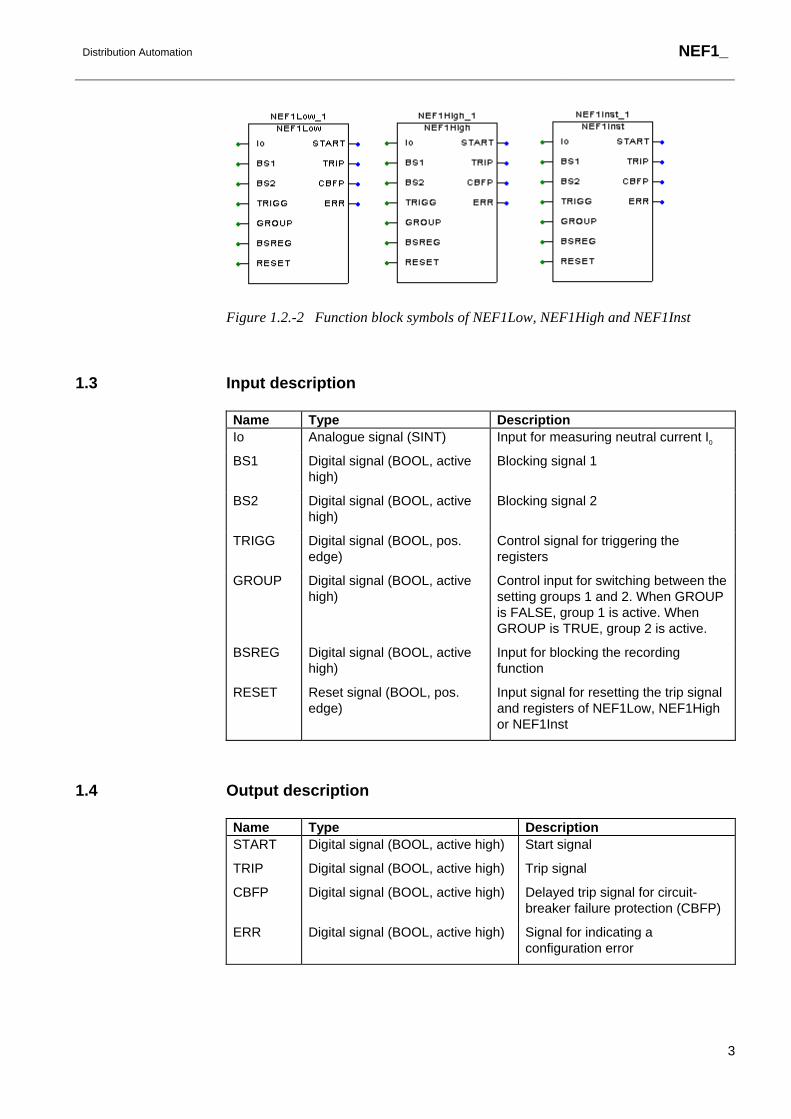
Figure 1.2.-2 Function block symbols of NEF1Low, NEF1High and NEF1Inst
1.3 Input description
Name Type Description Io Analogue signal (SINT) Input for measuring neutral current I0
BS1 Digital signal (BOOL, active high)
Blocking signal 1
BS2 Digital signal (BOOL, active high)
Blocking signal 2
TRIGG Digital signal (BOOL, pos. edge)
Control signal for triggering the registers
GROUP Digital signal (BOOL, active high)
Control input for switching between the setting groups 1 and 2. When GROUP is FALSE, group 1 is active. When GROUP is TRUE, group 2 is active.
BSREG Digital signal (BOOL, active high)
Input for blocking the recording function
RESET Reset signal (BOOL, pos. edge)
Input signal for resetting the trip signal and registers of NEF1Low, NEF1High or NEF1Inst
1.4 Output description
Name Type Description START Digital signal (BOOL, active high) Start signal
TRIP Digital signal (BOOL, active high) Trip signal
CBFP Digital signal (BOOL, active high) Delayed trip signal for circuit-breaker failure protection (CBFP)
ERR Digital signal (BOOL, active high) Signal for indicating a configuration error

NEF1_
Distribution Automation
4
2. Description of operation
2.1 Configuration
Neutral current I0 can be measured with a conventional current transformer. If the neutral of the network is either isolated or earthed by a high impedance, a core balance current transformer is recommended to be used in earth fault protection. To ensure sufficient accuracy of neutral current measurements and consequently the selectivity of the scheme, core balance current transformers should have a transformation ratio of at least 70:1. Lower transformation ratios like 50:1 or 50:5 are not recommended.
The measuring devices and signal types for analogue channels are selected and configured in a special dialogue box of the Relay Configuration Tool included in the CAP 505 Tool Box. Digital inputs are configured in the same programming environment (the number of selectable analogue inputs, digital inputs and digital outputs depends on the type of the hardware used).
When the analogue channels and digital inputs have been selected and configured in the dialogue box, the inputs and outputs of the function block can be configured on a graphic worksheet of the configuration tool. The neutral current I0 can be connected to the Io input of the function block. Furthermore, digital inputs are connected to the Boolean inputs of the function block and in the same way, the outputs of the function block are connected to the output signals.
2.2 Measuring mode
The operation of the function block is based on two alternative measuring principles: the average value of consecutive instantaneous peak-to-peak values or the numerically calculated fundamental frequency component of the neutral current. The measuring mode is selected by means of an HMI parameter or a serial communication parameter.
With both the measuring principles, the operation is insensitive to the DC component and the operation accuracy is defined in the frequency range f/fn=0.95...1.05. In peak-to-peak measurement, the harmonics of the neutral current are not suppressed, whereas in fundamental frequency measurement the harmonics suppression is at least -50 dB at f = n x fn, where n = 2, 3, 4, 5,...
2.3 Operation criteria
The function block starts if the neutral current exceeds the set start current. When the function block starts, the START signal is set to TRUE. Should the duration of the earth fault exceed the set definite operate time or, at the inverse-time operation, the time determined by the level of the measured current, the function block operates. The internal delay of the heavy-duty output relay is included in the total operate time.

Distribution Automation
NEF1_
5
When the function block operates, the TRIP signal is set to TRUE. Operation mode instantaneous is selectable in the function blocks NEF1High and NEF1Inst. In instantaneous mode the TRIP signal is immediately activated.
The DT or IDMT timer is allowed to run only if the blocking signal BS1 is inactive, i.e. its value is FALSE. When the signal becomes active, i.e. its value turns to TRUE, the timer will be stopped (frozen).
When the blocking signal BS2 is active, the TRIP signal cannot be activated. The TRIP signal can be blocked by activating the signal BS2 until the function block drops off.
2.4 Delayed reset facility and drop-off time in DT and IDMT modes
The purpose of the delayed reset function is to enable fast clearance of intermittent faults, e.g. self-sealing insulation faults, and severe faults which may produce high asymmetrical fault currents that partially saturate the current transformers. It is typical for an intermittent fault that the fault current contains so-called drop-off periods during which the fault current is below the set start current. Without the delayed reset function the DT or the IDMT timer would reset once the current drops off. In the same way, an apparent drop-off period of the secondary current of the saturated current transformer might reset the DT or the IDMT timer. The adjustable delayed reset function also enables closer co-ordination with electromechanical induction disc relays.
When the DT timer has started, it goes on running normally even if the current drops off, provided the drop-off period is shorter than the set drop-off time. In the same situation, the IDMT timer is frozen. If the drop-off period is longer than the set drop-off time, the DT or the IDMT timer will be reset when the drop-off time elapses. The situation in the case of the DT timer is described in Figure 2.4.-1.
In Figures 2.4.-1 and 2.4.-2 the input signal IN of the DT timer is TRUE when the current is above the set start value and FALSE when the current is below the set start value.

NEF1_
Distribution Automation
6
Operate time
Drop-off time
IN
START
TRIP
0
1
Drop-offtimer
Operatetimer
Dro
poff1
.fh7
Figure 2.4.-1 The drop-off period is longer than the set drop-off time
If the drop-off period is shorter than the set drop-off time and the DT timer time has elapsed during the drop-off period, the function block will trip once the current exceeds the set value again (Figure 2.4.-2).
Operate time
Drop-off time
IN
START
TRIP
0
1
Drop-offtimer
Operatetimer D
ropo
ff2.fh
7
Figure 2.4.-2 The drop-off period is shorter than the set drop-off time
2.5 IDMT type operation of NEF1Low
In the inverse-time mode, the operate time of the stage is a function of the current. The higher the current, the shorter the operate time is. Fourteen time/current curve groups are available. Four of the groups comply with the BS 142 and IEC 60255 standards, whereas the two curve groups RI and RD (RXIDG) are special type of curve groups corresponding to the ABB praxis. Eight IEEE curves comply with the IEEE C37.112 standard. The setting "Operation mode" is used for selecting the desired operate time characteristic.

Distribution Automation
NEF1_
7
The shortest operate time at the inverse-time operation is limited by a special adjustable minimum time located in control settings. The definite minimum time will not allow operate times shorter than the set minimum time, which is why the inverse-time mode is called the IDMT mode (Inverse Definite Minimum Time).
2.5.1 Standard curve groups
The four internationally standardized inverse-time characteristics incorporated in the inverse-time operation of the function are:
• normal inverse (NI) • very inverse (VI) • extremely inverse (EI) • long-time inverse (LI) (For a graphical presentation of the curves, refer to the manual Technical Descriptions of Functions, Introduction.)
The relationship between time and current is in accordance with the standard IEC 60255-4 and can be expressed as follows
t[s]k x
II
( )=
>−1
βα
where
t operate time in seconds
k adjustable time multiplier, parameters S4, S44 and S74
I phase current
I> adjustable start current, parameters S2, S42 and S72
α, β constants to provide selected curve characteristics
The values of the constants a and b determine the slope as follows
Inverse-time characteristic
α β
Normal inverse 0.02 0.14
Very inverse 1.0 13.5
Extremely inverse 2.0 80.0
Long-time inverse 1.0 120
According to the standard BS 142: 1966 the effective current range is defined as 2...20 times the set start current. If the time/current characteristic is normal inverse, very

NEF1_
Distribution Automation
8
inverse or extremely inverse, the function has to start at the latest when the current exceeds the set start current by 1.3 times. For the long-time inverse characteristic, the effective current range is specified to be 2...7 times the set start current and the relay is to start at the latest when the current exceeds the setting value by 1.1 times. The function block NEF1Low will start and the IDMT integration will begin once the current exceeds the set start current.
The operate time tolerances specified by the standard BS 142 : 1966 are the following (E denotes the accuracy in percent):
I/I > Normal Very Extremely Long time 2 2.22E 2.34E 2.44E 2.34E
5 1.13E 1.26E 1.48E 1.26E
7 - - - 1.00E
10 1.01E 1.01E 1.02E -
20 1.00E 1.00E 1.00E -
The tolerance factors are in accordance to those defined by the standard BS 142: 1966 for currents 2 and 5 times the setting. The NEF1Low complies with the tolerances of class 5 (E = 5.0%) for all inverse-time curves.
For example:
I/I>= 10, characteristic = Normal Operate time tolerance = 1.01 x 5.0% = 5.05%
2.5.2 RI curve groups
The RI-type inverse-time characteristic is a special characteristic mainly used to obtain time grading with mechanical relays. The characteristic can be expressed as follows:
t sk
0.339 0.236 x I
I
=−
>
2.5.3 RD curve groups
The RD-type characteristic is a special characteristic mainly used in earth-fault protection where a high degree of selectivity is required also at high-resistance faults. Mathematically, the characteristic can be expressed as follows:

Distribution Automation
NEF1_
9
t[s] = 5.8 -1.35 x lnI
k x I > The accuracy of the RI- and RD-type characteristics is 5%. Also with the RI- and RD-type characteristics, the function block will start and the IDMT integration will begin once the current exceeds the set start current.
2.5.4 IEEE curve groups
IEEE time overcurrent curve equation according to the standard IEEE C37.112:
[ ] nB
II
AP ×
+
−
>
=
1 st
where
I> adjustable start current, parameters S2, S42 and S72
n adjustable IEEE time dial setting, parameters S5, S45 and S75
A, B, p constants to provide selected curve characteristics
Curve A B p IEEE Extremely Inverse 6.407 0.025 2.0
IEEE Very Inverse 2.855 0.0712 2.0
IEEE Inverse 0.0086 0.0185 0.02
IEEE Short Time Inverse 0.00172 0.0037 0.02
IEEE Short Time Ext. Inverse 1.281 0.005 2.0
IEEE Long Time Ext. Inv. 64.07 0.250 2.0
IEEE Long Time Very Inv. 28.55 0.712 2.0
IEEE Long Time Inverse 0.086 0.185 0.02
2.6 Setting groups
Two different groups of setting values, group 1 and group 2, are available for the function block. Switching between the two groups can be done in the following three ways:
1 Locally via the control parameter “Group selection”1) of the HMI 2 Over the serial bus with the command V31)

NEF1_
Distribution Automation
10
3 By means of the input signal GROUP when allowed via the parameter “Group selection” (i.e. when V3 = 21)). 1) Group selection (V3): 0 = Group 1; 1 = Group 2; 2 = GROUP input
The group settings come into effect immediately after selection. The control parameter "Active group" indicates that the setting group is valid at a given time.
2.7 Test mode
The digital outputs of the function block can be activated with separate control settings for each output either locally via the HMI or externally via the serial communication. When an output is activated with the test parameter, an event indicating the test is generated.
The protection functions operate normally while the outputs are tested.
2.8 START, TRIP and CBFP outputs
The output signal START is always pulse-shaped. The minimum pulse width of the START and TRIP output signals is set via a separate parameter on the HMI or on the serial communication. If the start situation is longer than the set pulse width, the START signal remains active until the start situation is over.
The output signal TRIP may have a non-latching or latching feature. If the start situation is longer than the set pulse width and the non-latching mode has been selected, the TRIP signal remains active until the start situation is over. When the latching mode has been selected, the TRIP signal remains active until the output is reset even if the operation criteria have reset.
The circuit-breaker failure protection function provides a delayed trip signal, CBFP, after the TRIP signal unless the fault has disappeared during the set CBFP time delay. The CBFP output can be used to operate a circuit breaker in front of the circuit breaker of the feeder.
Note! The control parameter "Trip pulse" also sets the pulse width of the CBFP output signal. The CBFP signal resets when the set pulse width elapses, even if the start situation is still active. Therefore, if the CBFP function is used, a setting value of 200ms or longer for the control parameter "Trip pulse" is recommended.

Distribution Automation
NEF1_
11
2.9 Resetting
The TRIP output signal and the registers can be reset either via the RESET input, or over the serial bus or the local HMI.
The operation indicators, latched trip signal and recorded data can be reset as follows:
Operation indicators
Latched trip signal
Recorded data
RESET input of the function block 1) X X
Parameter F038V013 for NEF1Low1) X X
Parameter F039V013 for NEF1High1) X X
Parameter F090V013 for NEF1Inst1) X X
General parameter F001V011 2) X
General parameter F001V012 2) X X
General parameter F001V013 2) X X X
Push-button C 2) X
Push-buttons C + E (2 s) 2) X X
Push-buttons C + E (5 s) 2) X X X 1) Resets the latched trip signal and recorded data of the particular function block. 2) Affects all function blocks.
NEF1_
Distribution Automation
12
3. Parameters and events
3.1 General
• Each function block has a specific channel number for serial communication parameters and events. The channel for NEF1Low is 38, that for NEF1High 39 and that for NEF1Inst 90.
• The data direction of the parameters defines the use of each parameter as follows: Data direction Description R, R/M Read only
W Write only
R/W Read and write
• The different event mask parameters (see section “Control settings”) affect the visibility of events on the HMI or on serial communication (LON or SPA) as follows: Event mask 1 (FxxxV101/102) SPA / HMI (LON)
Event mask 2 (FxxxV103/104) LON
Event mask 3 (FxxxV105/106) LON
Event mask 4 (FxxxV107/108) LON
For example, if only the events E3, E4 and E5 are to be seen on the HMI of the relay terminal, the event mask value 56 (8 + 16 + 32) is written to the “Event mask 1” parameter (FxxxV101). In case a function block includes more than 32 events, there are two parameters instead of e.g. the “Event mask 1” parameter: the parameter “Event mask 1A” (FxxxV101) covers the events 0...31 and “Event mask 1B”(FxxxV102) the events 32...63.
Distribution Automation
NEF1_
13
3.2 Setting values
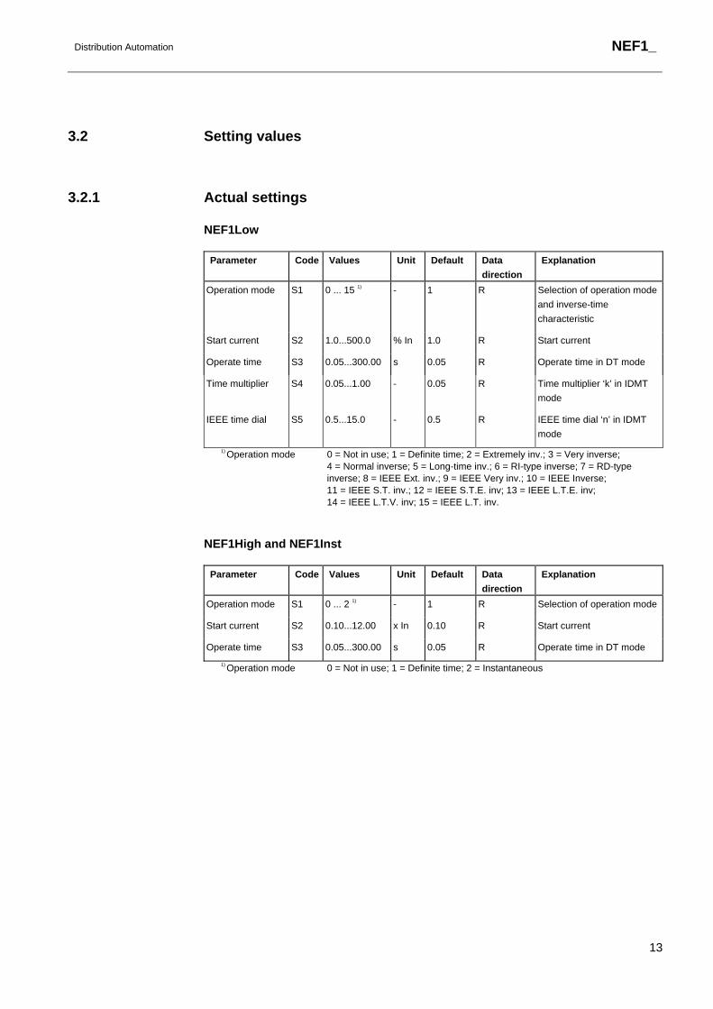
3.2.1 Actual settings
NEF1Low
Parameter Code Values Unit Default Data direction
Explanation
Operation mode S1 0 ... 15 1) - 1 R Selection of operation mode
and inverse-time
characteristic
Start current S2 1.0...500.0 % In 1.0 R Start current
Operate time S3 0.05...300.00 s 0.05 R Operate time in DT mode
Time multiplier S4 0.05...1.00 - 0.05 R Time multiplier ‘k’ in IDMT
mode
IEEE time dial S5 0.5...15.0 - 0.5 R IEEE time dial ‘n’ in IDMT
mode
1) Operation mode 0 = Not in use; 1 = Definite time; 2 = Extremely inv.; 3 = Very inverse; 4 = Normal inverse; 5 = Long-time inv.; 6 = RI-type inverse; 7 = RD-type inverse; 8 = IEEE Ext. inv.; 9 = IEEE Very inv.; 10 = IEEE Inverse; 11 = IEEE S.T. inv.; 12 = IEEE S.T.E. inv; 13 = IEEE L.T.E. inv; 14 = IEEE L.T.V. inv; 15 = IEEE L.T. inv.
NEF1High and NEF1Inst
Parameter Code Values Unit Default Data direction
Explanation
Operation mode S1 0 ... 2 1) - 1 R Selection of operation mode
Start current S2 0.10...12.00 x In 0.10 R Start current
Operate time S3 0.05...300.00 s 0.05 R Operate time in DT mode
1) Operation mode 0 = Not in use; 1 = Definite time; 2 = Instantaneous

NEF1_
Distribution Automation
14
3.2.2 Setting group 1
NEF1Low
Parameter Code Values Unit Default Data direction
Explanation
Operation mode S41 0 ... 15 1) - 1 R/W Selection of operation mode
and inverse-time
characteristic
Start current S42 1.0...500.0 % In 1.0 R/W Start current
Operate time S43 0.05...300.00 s 0.05 R/W Operate time in DT mode
Time multiplier S44 0.05...1.00 - 0.05 R/W Time multiplier ‘k’ in IDMT
mode
IEEE time dial S45 0.5...15.0 - 0.5 R/W IEEE time dial ‘n’ in IDMT
mode
1) Operation mode 0 = Not in use; 1 = Definite time; 2 = Extremely inv.; 3 = Very inverse; 4 = Normal inverse; 5 = Long-time inv.; 6 = RI-type inverse; 7 = RD-type inverse; 8 = IEEE Ext. inv.; 9 = IEEE Very inv.; 10 = IEEE Inverse; 11 = IEEE S.T. inv.; 12 = IEEE S.T.E. inv; 13 = IEEE L.T.E. inv; 14 = IEEE L.T.V. inv; 15 = IEEE L.T. inv.
NEF1High and NEF1Inst
Parameter Code Values Unit Default Data direction
Explanation
Operation mode S41 0 ... 2 1) - 1 R/W Selection of operation mode
Start current S42 0.10...12.00 x In 0.10 R/W Start current
Operate time S43 0.05...300.00 s 0.05 R/W Operate time in DT mode
1) Operation mode 0 = Not in use; 1 = Definite time; 2 = Instantaneous

Distribution Automation
NEF1_
15
3.2.3 Setting group 2
NEF1Low
Parameter Code Values Unit Default Data direction
Explanation
Operation mode S71 0 ... 15 1) - 1 R/W Selection of operation mode
and inverse-time
characteristic
Start current S72 1.0...500.0 % In 1.0 R/W Start current
Operate time S73 0.05...300.00 s 0.05 R/W Operate time in DT mode
Time multiplier S74 0.05...1.00 - 0.05 R/W Time multiplier ‘k’ in IDMT
mode
IEEE time dial S75 0.5...15.0 - 0.5 R/W IEEE time dial ‘n’ in IDMT
mode
1) Operation mode 0 = Not in use; 1 = Definite time; 2 = Extremely inv.; 3 = Very inverse; 4 = Normal inverse; 5 = Long-time inv.; 6 = RI-type inverse; 7 = RD-type inverse; 8 = IEEE Ext. inv.; 9 = IEEE Very inv.; 10 = IEEE Inverse; 11 = IEEE S.T. inv.; 12 = IEEE S.T.E. inv; 13 = IEEE L.T.E. inv; 14 = IEEE L.T.V. inv; 15 = IEEE L.T. inv.
NEF1High and NEF1Inst
Parameter Code Values Unit Default Data direction
Explanation
Operation mode S71 0 ... 2 1) - 1 R/W Selection of operation mode
Start current S72 0.10...12.00 x In 0.10 R/W Start current
Operate time S73 0.05...300.00 s 0.05 R/W Operate time in DT mode
1) Operation mode 0 = Not in use; 1 = Definite time; 2 = Instantaneous

NEF1_
Distribution Automation
16
3.2.4 Control settings
NEF1Low
Parameter Code Values Unit Default Data direction
Explanation
Measuring mode V1 0 or 1 1) - 1 R/W Selection of measuring mode
Drop-off time V2 0...1000 ms 0 R/W Resetting time of the operate time counter
Group selection V3 0 ... 2 2) - 0 R/W Selection of the active setting group
Active group V4 0 or 1 3) - 0 R/M Active setting group
Start pulse V5 0...1000 ms 0 R/W Minimum pulse width of
START signal
Trip signal V6 0 or 1 4) - 0 R/W Selection of latching feature for TRIP output
Trip pulse V7 40...1000 ms 40 R/W Minimum pulse width of TRIP and CBFP
Minimum time V8 0.03...10.0
0
s 0.03 R/W Minimum operate time in IDMT mode
CBFP time V9 100...1000 ms 100 R/W Operate time of the delayed
trip CBFP
Reset registers V13 1=Reset - 0 W Resetting of latched trip signal and registers
Test START V31 0 or 1 5) - 0 R/W Testing of START
Test TRIP V32 0 or 1 5) - 0 R/W Testing of TRIP
Test CBFP V33 0 or 1 5) - 0 R/W Testing of CBFP
Event mask 1 V101 0...4095 - 63 R/W Event mask 1 for event
transmission (E0 ... E11)
Event mask 2 V103 0...4095 - 63 R/W Event mask 2 for event transmission (E0 ... E11)
Event mask 3 V105 0...4095 - 63 R/W Event mask 3 for event transmission (E0 ... E11)
Event mask 4 V107 0...4095 - 63 R/W Event mask 4 for event transmission (E0 ... E11)
1) Measuring mode 0 = Peak-to-peak; 1 = Fundam.freq. 2) Group selection 0 = Group 1; 1 = Group 2; 2 = GROUP input 3) Active group 0 = Group 1; 1 = Group 2 4) Trip signal 0 = Non-latching; 1 = Latching 5) Test 0 = Do not activate; 1 = Activate

Distribution Automation
NEF1_
17
NEF1High and NEF1Inst
Parameter Code Values Unit Default Data direction
Explanation
Measuring mode V1 0 or 1 1) - 1 R/W Selection of measuring mode
Drop-off time V2 0...1000 ms 0 R/W Resetting time of the operate time counter
Group selection V3 0 ... 2 2) - 0 R/W Selection of the active setting group
Active group V4 0 or 1 3) - 0 R/M Active setting group
Start pulse V5 0...1000 ms 0 R/W Minimum pulse width of
START signal
Trip signal V6 0 or 1 4) - 0 R/W Selection of latching feature for TRIP output
Trip pulse V7 40...1000 ms 40 R/W Minimum pulse width of TRIP and CBFP
CBFP time V8 100...1000 ms 100 R/W Operate time of the delayed
trip CBFP
Reset registers V13 1=Reset - 0 W Resetting of latched trip signal and registers
Test START V31 0 or 1 5) - 0 R/W Testing of START
Test TRIP V32 0 or 1 5) - 0 R/W Testing of TRIP
Test CBFP V33 0 or 1 5) - 0 R/W Testing of CBFP
Event mask 1 V101 0...4095 - 63 R/W Event mask 1 for event
transmission (E0 ... E11)
Event mask 2 V103 0...4095 - 63 R/W Event mask 2 for event transmission (E0 ... E11)
Event mask 3 V105 0...4095 - 63 R/W Event mask 3 for event transmission (E0 ... E11)
Event mask 4 V107 0...4095 - 63 R/W Event mask 4 for event transmission (E0 ... E11)
1) Measuring mode 0 = Peak-to-peak; 1 = Fundam.freq. 2) Group selection 0 = Group 1; 1 = Group 2; 2 = GROUP input 3) Active group 0 = Group 1; 1 = Group 2 4) Trip signal 0 = Non-latching; 1 = Latching 5) Test 0 = Do not activate; 1 = Activate
NEF1_
Distribution Automation
18
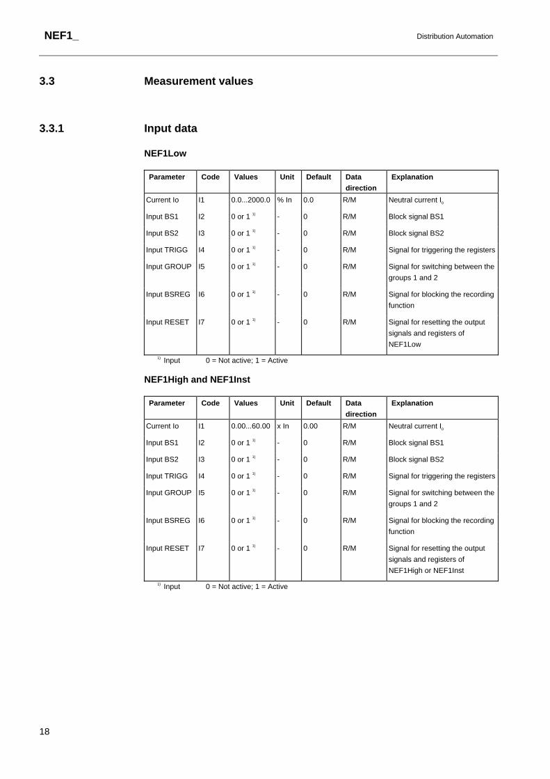
3.3 Measurement values
3.3.1 Input data
NEF1Low
Parameter Code Values Unit Default Data direction
Explanation
Current Io I1 0.0...2000.0 % In 0.0 R/M Neutral current I0
Input BS1 I2 0 or 1 1) - 0 R/M Block signal BS1
Input BS2 I3 0 or 1 1) - 0 R/M Block signal BS2
Input TRIGG I4 0 or 1 1) - 0 R/M Signal for triggering the registers
Input GROUP I5 0 or 1 1) - 0 R/M Signal for switching between the
groups 1 and 2
Input BSREG I6 0 or 1 1) - 0 R/M Signal for blocking the recording
function
Input RESET I7 0 or 1 1) - 0 R/M Signal for resetting the output
signals and registers of
NEF1Low
1) Input 0 = Not active; 1 = Active
NEF1High and NEF1Inst
Parameter Code Values Unit Default Data direction
Explanation
Current Io I1 0.00...60.00 x In 0.00 R/M Neutral current I0
Input BS1 I2 0 or 1 1) - 0 R/M Block signal BS1
Input BS2 I3 0 or 1 1) - 0 R/M Block signal BS2
Input TRIGG I4 0 or 1 1) - 0 R/M Signal for triggering the registers
Input GROUP I5 0 or 1 1) - 0 R/M Signal for switching between the
groups 1 and 2
Input BSREG I6 0 or 1 1) - 0 R/M Signal for blocking the recording
function
Input RESET I7 0 or 1 1) - 0 R/M Signal for resetting the output
signals and registers of
NEF1High or NEF1Inst
1) Input 0 = Not active; 1 = Active

Distribution Automation
NEF1_
19
3.3.2 Output data
Parameter Code Values Unit Default Data direction
Explanation
Output START O1 0 or 1 1) - 0 R/M Status of start signal
Output TRIP O2 0 or 1 1) - 0 R/M Status of trip signal
Output CBFP O3 0 or 1 1) - 0 R/M Status of CBFP signal
1) Output 0 = Not active; 1 = Active
3.3.3 Recorded data
3.3.3.1 General
The information required for later fault analysis is recorded when the function block starts or trips, or when the recording function is triggered via an external triggering input.
The data of the last three events are stored in Recorded data 1…3, beginning from Recorded data 1. These registers are updated in a cyclical manner, where the values of the most recent event overwrite the oldest recorded data. If recorded data has been reset or the relay has been restarted, the first event is again stored in Recorded data 1.
The recording function can be blocked via the BSREG input. For example, if an auto-reclose sequence is initiated by the trip signal of the function block, the values most reliable for later fault analysis are those recorded just before Shot 1. When the auto-reclose sequence has started, no recordings are needed at the moment of tripping. The output signal ACTIVE in AR5Func indicating AR in progress is connected to the BSREG input to prevent useless recording.
3.3.3.2 Date and time
The time stamp indicates the rising edge of the START, TRIP or TRIGG signal.
3.3.3.3 Duration
In the DT mode of operation the duration of the start situation is recorded as a percentage of the set operate time and, as concerns NEF1Low, in the IDMT mode of operation as a percentage of the calculated operate time.

NEF1_
Distribution Automation
20
3.3.3.4 Neutral current
If the function block trips, the current values are updated at the moment of tripping i.e. on the rising edge of the signal TRIP. For external triggering the current values are updated at the moment of triggering i.e. on the rising edge of the input signal TRIGG. If the function block starts but does not trip, the neutral current value captured one fundamental cycle (20 ms at rated frequency 50 Hz) after the beginning of the start situation is recorded. The value of the neutral current I0 is recorded as a multiple of the rated current In.
3.3.3.5 Status data
The status data of the input signals BS1 and BS2 as well as the “Active group” parameter are recorded at the moment of recording. The “Active group” parameter indicates the setting group valid for the recorded data.
3.3.3.6 Priority
The priority of the recording function is the following:
1 Tripping 2 Starting 3 External triggering, which means that if the function block has started, it will neglect an external triggering request.

Distribution Automation
NEF1_
21
3.3.3.7 Recorded data 1
NEF1Low
Parameter Code Values Unit Default Data direction
Explanation
Date V201 YYYY-MM-DD - - R/M Recording date
Time V202 hh:mm:ss.mss - - R/M Recording time
Duration V203 0.0...100.0 % 0.0 R/M Duration of start situation
Io mean V204 0.0...2000.0 % In 0.0 R/M Filtered value of I0
Io peak V205 0.0...2000.0 % In 0.0 R/M Momentary peak of I0
BS1 V206 0 or 1 1) - 0 R/M Status of BS1 input
BS2 V207 0 or 1 1) - 0 R/M Status of BS2 input
Active group V208 0 or 1 2) - 0 R/M Active setting group
1) BS_ 0 = Not active; 1 = Active 2) Active group 0 = Group 1; 1 = Group 2
NEF1High and NEF1Inst
Parameter Code Values Unit Default Data direction
Explanation
Date V201 YYYY-MM-DD - - R/M Recording date
Time V202 hh:mm:ss.mss - - R/M Recording time
Duration V203 0.0...100.0 % 0.0 R/M Duration of start situation
Io mean V204 0.00...60.00 x In 0.00 R/M Filtered value of I0
Io peak V205 0.00...60.00 x In 0.00 R/M Momentary peak of I0
BS1 V206 0 or 1 1) - 0 R/M Status of BS1 input
BS2 V207 0 or 1 1) - 0 R/M Status of BS2 input
Active group V208 0 or 1 2) - 0 R/M Active setting group
1) BS_ 0 = Not active; 1 = Active 2) Active group 0 = Group 1; 1 = Group 2

NEF1_
Distribution Automation
22
3.3.3.8 Recorded data 2
NEF1Low
Parameter Code Values Unit Default Data direction
Explanation
Date V301 YYYY-MM-DD - - R/M Recording date
Time V302 hh:mm:ss.mss - - R/M Recording time
Duration V303 0.0...100.0 % 0.0 R/M Duration of start situation
Io mean V304 0.0...2000.0 % In 0.0 R/M Filtered value of I0
Io peak V305 0.0...2000.0 % In 0.0 R/M Momentary peak of I0
BS1 V306 0 or 1 1) - 0 R/M Status of BS1 input
BS2 V307 0 or 1 1) - 0 R/M Status of BS2 input
Active group V308 0 or 1 2) - 0 R/M Active setting group
1) BS_ 0 = Not active; 1 = Active 2) Active group 0 = Group 1; 1 = Group 2
NEF1High and NEF1Inst
Parameter Code Values Unit Default Data direction
Explanation
Date V301 YYYY-MM-DD - - R/M Recording date
Time V302 hh:mm:ss.mss - - R/M Recording time
Duration V303 0.0...100.0 % 0.0 R/M Duration of start situation
Io mean V304 0.00...60.00 x In 0.00 R/M Filtered value of I0
Io peak V305 0.00...60.00 x In 0.00 R/M Momentary peak of I0
BS1 V306 0 or 1 1) - 0 R/M Status of BS1 input
BS2 V307 0 or 1 1) - 0 R/M Status of BS2 input
Active group V308 0 or 1 2) - 0 R/M Active setting group
1) BS_ 0 = Not active; 1 = Active 2) Active group 0 = Group 1; 1 = Group 2

Distribution Automation
NEF1_
23
3.3.3.9 Recorded data 3
NEF1Low
Parameter Code Values Unit Default Data direction
Explanation
Date V401 YYYY-MM-DD - - R/M Recording date
Time V402 hh:mm:ss.mss - - R/M Recording time
Duration V403 0.0...100.0 % 0.0 R/M Duration of start situation
Io mean V404 0.0...2000.0 % In 0.0 R/M Filtered value of I0
Io peak V405 0.0...2000.0 % In 0.0 R/M Momentary peak of I0
BS1 V406 0 or 1 1) - 0 R/M Status of BS1 input
BS2 V407 0 or 1 1) - 0 R/M Status of BS2 input
Active group V408 0 or 1 2) - 0 R/M Active setting group
1) BS_ 0 = Not active; 1 = Active 2) Active group 0 = Group 1; 1 = Group 2
NEF1High and NEF1Inst
Parameter Code Values Unit Default Data direction
Explanation
Date V401 YYYY-MM-DD - - R/M Recording date
Time V402 hh:mm:ss.mss - - R/M Recording time
Duration V403 0.0...100.0 % 0.0 R/M Duration of start situation
Io mean V404 0.00...60.00 x In 0.00 R/M Filtered value of I0
Io peak V405 0.00...60.00 x In 0.00 R/M Momentary peak of I0
BS1 V406 0 or 1 1) - 0 R/M Status of BS1 input
BS2 V407 0 or 1 1) - 0 R/M Status of BS2 input
Active group V408 0 or 1 2) - 0 R/M Active setting group
1) BS_ 0 = Not active; 1 = Active 2) Active group 0 = Group 1; 1 = Group 2
NEF1_
Distribution Automation
24
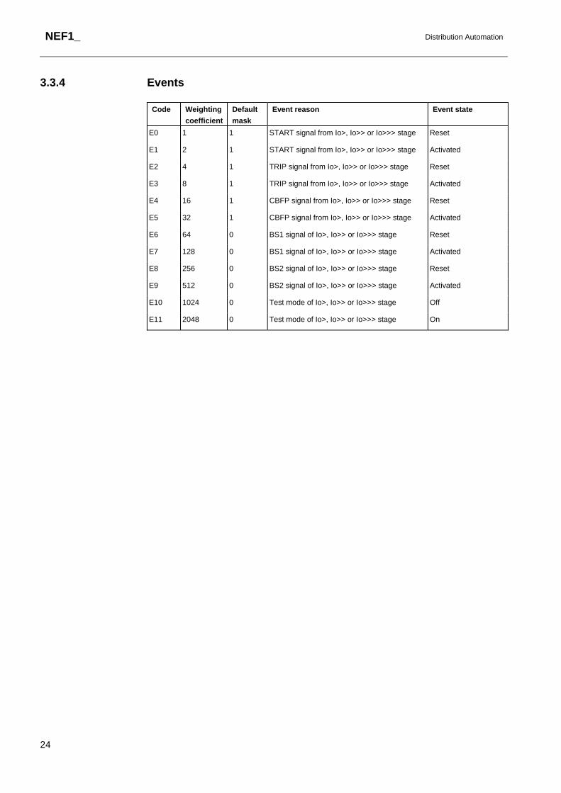
3.3.4 Events
Code Weighting coefficient
Default mask
Event reason Event state
E0 1 1 START signal from Io>, Io>> or Io>>> stage Reset
E1 2 1 START signal from Io>, Io>> or Io>>> stage Activated
E2 4 1 TRIP signal from Io>, Io>> or Io>>> stage Reset
E3 8 1 TRIP signal from Io>, Io>> or Io>>> stage Activated
E4 16 1 CBFP signal from Io>, Io>> or Io>>> stage Reset
E5 32 1 CBFP signal from Io>, Io>> or Io>>> stage Activated
E6 64 0 BS1 signal of Io>, Io>> or Io>>> stage Reset
E7 128 0 BS1 signal of Io>, Io>> or Io>>> stage Activated
E8 256 0 BS2 signal of Io>, Io>> or Io>>> stage Reset
E9 512 0 BS2 signal of Io>, Io>> or Io>>> stage Activated
E10 1024 0 Test mode of Io>, Io>> or Io>>> stage Off
E11 2048 0 Test mode of Io>, Io>> or Io>>> stage On

Distribution Automation
NEF1_
25
4. Technical data Operation accuracies Depends on the frequency of the current measured:
NEF1Low:
f/fn= 0.95...1.05: ±2.5% of set value + 0.0005 x In.
NEF1High and NEF1Inst:
f/fn= 0.95...1.05: ±2.5% of set value or ±0.01 x In.
Start time Injected currents > 2.0 x start current:
f/fn = 0.95...1.05 internal time < 32 ms
total time1) < 40 ms
Reset time 40...1000 ms (depends on the set minimum output pulse width)
Reset ratio Typ. 0.95 (range 0.95...0.98)
Retardation time Total retardation time when the current drops
below the start value2)
< 45 ms
Operate time accuracy in definite-time mode
Depends on the frequency of the current measured:
f/fn = 0.95...1.05: ± 2% of set value or ± 20 ms2)
Accuracy class index E in inverse-time mode
Depends on the frequency of the current measured:
(NEF1Low) f/fn = 0.95...1.05: Class index E = 5.0 or ±20 ms2)
Suppression of harmonics Measuring mode
0 No suppression
1 -50 dB at f = n x fn, where n = 2, 3, 4, 5,...
Configuration data Task execution interval (Relay Configuration Tool): 10 ms,
at the rated frequency fn = 50 Hz
1) Includes the delay of the signal relay 2) Includes the delay of the heavy-duty output relay
Technical revision history
Function block Technical revision
Change
NEF1Low B -
C -
D Added IEEE IDMT curves
E Extended start current setting range
NEF1High B -
C -
NEF1Inst B -
C (No change in the manual)
D -