3 mev test stand measurement plans
DESCRIPTION
3 MeV test stand measurement plans. A. Lombardi for the LINAC4 team. Scope. Validate Source and LEBT design RFQ design Chopper. Source 45 keV. Chopper. Diagnostic line. RFQ 3 MeV. LINAC end-to-end. Location and causes of e growth and losses: - PowerPoint PPT PresentationTRANSCRIPT

BCC 41 - 3MeV test stand measurements 1
3 MeV test stand measurement plans
A. Lombardi for the LINAC4 team
10/01/2013
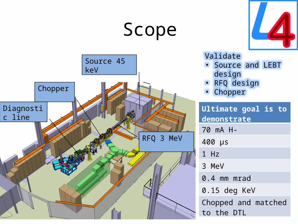
Scope Validate • Source and LEBT design• RFQ design • Chopper
Ultimate goal is to demonstrate
70 mA H-
400 µs
1 Hz
3 MeV
0.4 mm mrad
0.15 deg KeV
Chopped and matched to the DTL
Source 45 keV
RFQ 3 MeV
Chopper
Diagnostic line
LINAC end-to-end
0
20
40
60
80
100
120
140
160
180
0 10 20 30 40 50 60 70 80
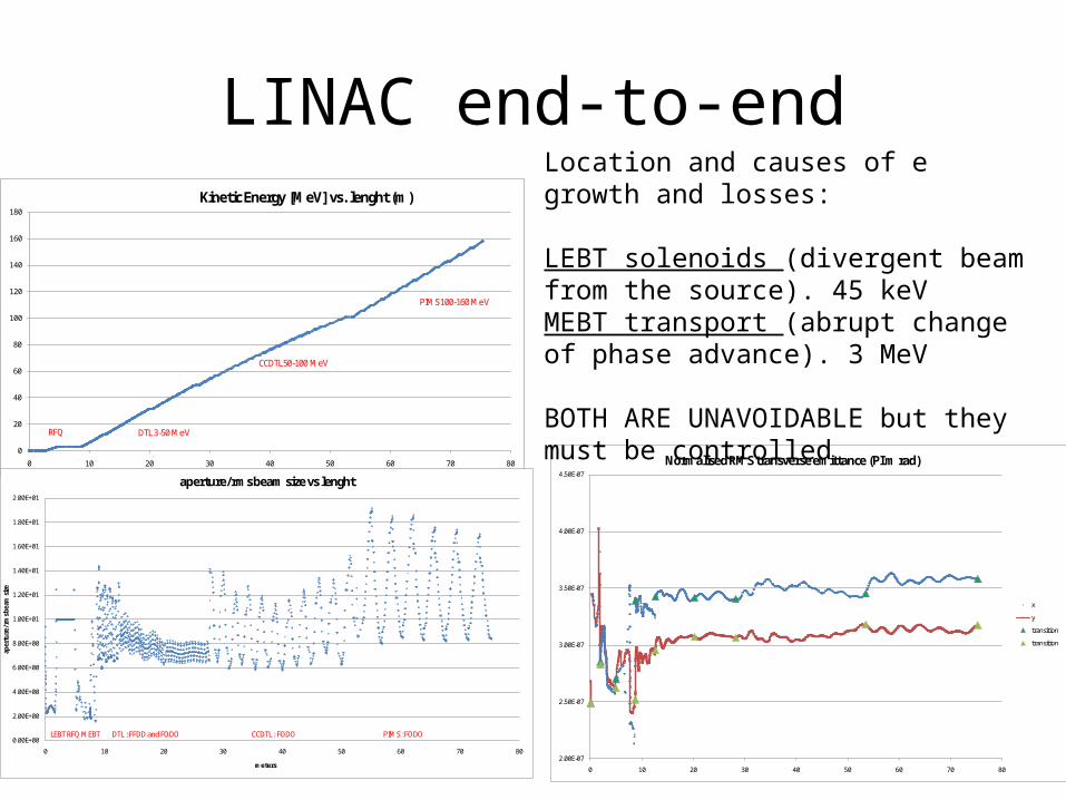
Kinetic Energy [MeV] vs. lenght (m)
RFQ DTL 3-50 MeV
CCDTL 50-100 MeV
PIMS 100-160 MeV
2.00E-07
2.50E-07
3.00E-07
3.50E-07
4.00E-07
4.50E-07
0 10 20 30 40 50 60 70 80
Normalised RMS transverse emittance (PI m rad)
x
y
transition
transition
Location and causes of e growth and losses:
LEBT solenoids (divergent beam from the source). 45 keVMEBT transport (abrupt change of phase advance). 3 MeV
BOTH ARE UNAVOIDABLE but they must be controlled
0.00E+00
2.00E+00
4.00E+00
6.00E+00
8.00E+00
1.00E+01
1.20E+01
1.40E+01
1.60E+01
1.80E+01
2.00E+01
0 10 20 30 40 50 60 70 80
aper
ture
/rm
s bea
m si
ze
meters
aperture/rms beam size vs lenght
DTL : FFDD and FODOLEBT RFQ MEBT CCDTL : FODO PIMS : FODO

Emittance 0-3 MeV
2.00E-07
2.50E-07
3.00E-07
3.50E-07
4.00E-07
4.50E-07
5.00E-07
5.50E-07
6.00E-07
0 2 4 6 8 10 12
normalised RMS-Emittance [m.rad] vs lenght
(X,BGX') RMS-Emittance [m.rad]
(Y,BGY') RMS-Emittance [m.rad]
Symmetry x,y in LEBT, if source is symmetric
Losses in the RFQ, emittance decreases
Losses and emittance increase when matching to the DTL
BCC 41 - 3MeV test stand measurements 5
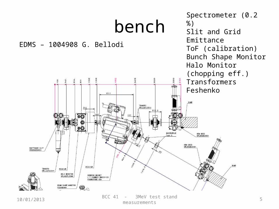
bench
10/01/2013
Spectrometer (0.2 %)Slit and Grid EmittanceToF (calibration)Bunch Shape MonitorHalo Monitor (chopping eff.)TransformersFeshenko
EDMS – 1004908 G. Bellodi

BCC 41 - 3MeV test stand measurements 6
Measurement plan – 1/2
10/01/2013
Stage 1 – after the RFQ 9 parameters : 2 solenoids, RFQ amplitude, 2 quads , 2 steerers
Scan Minimum beam
1) RFQ Transmission Solenoids, RF power Initially I =20 mA (min) Emi= 0.5 (max)
Needs I=70 mAEmi = 0.25 to fully validate.
2) RFQ emittance Solenoids, RF power
3) RFQ energy spread/longitudinal emitt
Solenoids, RF power
NEED TO ACHIEVE TRANSMISSION THROUGH THE RFQ OF 80% TO GO TO THE NEXT STAGE (NOMINAL TRANSMISSION IS 92%)

BCC 41 - 3MeV test stand measurements 7
Measurement plan – 2/2
10/01/2013
Stage 2 – after the chopper30 parameters : stage 1 parameters + 11 quads, 3 RF ampli, 3 RF phases, chopper voltage, 2 steerers
Scan Minimum beam At RFQ input
1) Transmission All parameters Initially I =50 mA (min) Emi= 0.4 (max)
Needs I=70 mAEmi = 0.25 to fully validate.
2) CHOPPING Pencil beamAll quads
3) Transverseemittance4) Longitudinal plane Buncher settings
FULL CHARACTERISATION IS NOT POSSIBLE, BUT GIVE PRIORITY TO THE MORES CRITICAL ITEMS

Pencil beam All elements on Chooper on (top) Chopper off (bottom)
With this we validate :1) Chopper voltage2) Optics
we do not validate : 3) Space charge4) Rise/fall time
MOST IMPORTANT MEAS
BEAM AT THE ws JUST BEFORE THE INLINE DUMP
OP DAY - 26th January 2012 Archamps 9
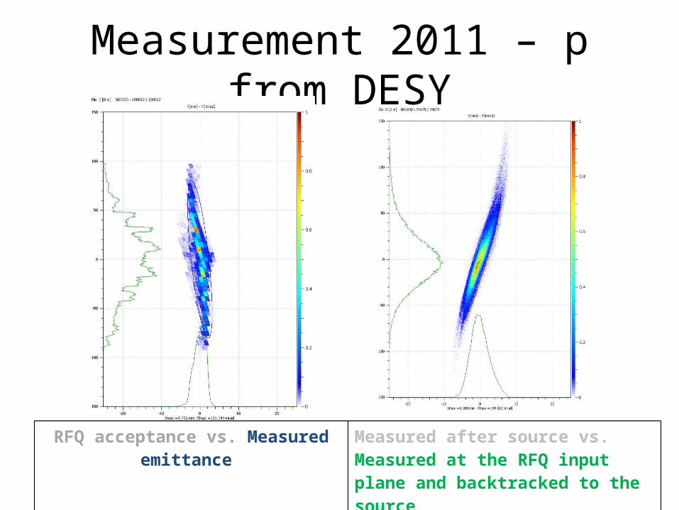
Measurement 2011 – p from DESY
RFQ acceptance vs. Measured emittance Measured after source vs. Measured at the RFQ input plane and backtracked to the source

BCC 41 - 3MeV test stand measurements 10
Protons• Already discussed – EDMS 1096658 • Measurement with Desy source in proton mode
(2011) gave an excellent insight into LEBT dynamics and solenoid modelling
To be done before protons are usable : • optimise to reach a min of 50-60 mA after the first
solenoid, • measure emittance vs. solenoid settings (5-10) and
back-trace to source input : create a beam for simulating/optimising the whole test stand.
10/01/2013

BCC 41 - 3MeV test stand measurements 11
Sharing the test stand- proposal(change over takes ½ day to 1 day)
• Run in proton mode until the emittance metre has to be dismantled
• Source development till RFQ ready for beam• Share 2:1 between 3 MeV measurements and
source development, over 3 weeks period or as best convenient.
• DO NOT FORGET COMMISSIONING TIME FOR DIAGNOSTICS
10/01/2013
BCC 41 - 3MeV test stand measurements 12
Proposal -
• 3 MeV beam commissioning must be done in 2 sessions/day on the basis 5 days/week . E.g. 7:00- 14:00 and 14-21
• We (BD team) are 3 staff + 3 visitors
• Daily brief meeting with the people on the field + 1 by-weekly meeting in the control room to take decisions – CALLED BY GB
• Need experts available as much as possible (in 2011 we “took it easy” but it took 6 months to measure the LEBT!)
10/01/2013

BCC 41 - 3MeV test stand measurements 13
Something has to give…• Laser stripping measurements ( make sure that BI is made aware)• Halo measurements under different matching• Matching to the DTL • Buncher optimisation • Pencil beam scans • Calibration of TOF vs. spectrometre…….. And many more
10/01/2013
The time presently allocated for commissioning in the tunnel is not sufficient-need 6 months
We should repeat the measurements after the RFQ in the tunnel