3 lifting devices
TRANSCRIPT

7/31/2019 3 Lifting Devices
http://slidepdf.com/reader/full/3-lifting-devices 1/281
NNNOOOTTTEEE CCCAAARRREEEFFFUUULLLLLLYYY
The following document was developed by
Learning Materials Production, OTEN, DET.
Adaptation of this material requires the observation of moral rights obligationsregarding attributions to source and author. For example:
This material was adapted from ‘(Title of LMP material)’ produced by Learning Materials Production, OTEN.
Furthermore, this material contains 3rd party copyright items which limits the wayit can be used. To clarify which items are 3rd party copyright, contact the CLICopyright Unit on (02) 9715 8000.
For further information about the use of the DET copyright licences under Part
VB of the Copyright Act 1968 see:http://www.copyright.com.au/educational_institutions.htm
Use of the 3rd party copyright elements in this material should comply with conditionsof the CAL (Copyright Agency Limited) Electronic Reproduction and CommunicationLicence. Please read and observe the following:
UUUSSSEEE OOOFFF 333RRRDDD PPPAAARRRTTTYYY ©©© MMMAAATTTEEERRRIIIAAALLL OOONNN EEE---MMMEEEDDDIIIAAA UUUNNNDDDEEERRR TTTHHHEEE CCCAAALLL LLLIIICCCEEENNNCCCEEESSS
Material may be communicated for the purposes of NSW DET on CD ROM/Intranetproviding the terms and conditions of the Copyright Agency Limited [CAL]Electronic Reproduction and Communication Licence and the Education HardcopyLicence are followed. Material containing third party copyright items producedunder the licences may not be sold for profit under this scheme.
Teachers may tailor materials for their own students but may not interfere with theintegrity of third party copyright materials or their accompanying citation. It is a legalrequirement that the moral rights of creators of these works is respected.
The following principles must be observed with regard to 3rd party copyright elements:
WarnThe Commonwealth Government Warning Notice below must appear at the head of anyadaptation that includes 3rd party copyright items communicated electronically. Thisnotice does not have to be included when the materials are printed.
ObserveObserve CAL limits. Items must comply with the CAL limits which are different underthe electronic use notice compared to the provisions under the hardcopy licence.
Full details of the guidelines entitled ‘Copying rights for educational institutions’ can
be found at:http://www.copyright.com.au/educational_institutions.htm

7/31/2019 3 Lifting Devices
http://slidepdf.com/reader/full/3-lifting-devices 2/281
AccessAccess must be limited to the educational purposes of NSW DET and not fordissemination to the wider public.
Acknowledge
All items must comply with Moral Rights legislation of 21/12/2000 and attributions mustbe correctly given and the integrity of the material respected. The latter also means that3rd party copyright items may not be adapted without the permission of therightsholder.
The following Warning Notice must be included with any 3r d party copyright items communicatedelectronically:

7/31/2019 3 Lifting Devices
http://slidepdf.com/reader/full/3-lifting-devices 3/281
COMMONWEALTH OF AUSTRALIA
Copyright Regulations 1969
WARNING
This material has been reproduced and communicated to you by or on behalf of the Centre for Learning Innovation, DET,
pursuant to Part VB of the Copyright Act 1968 (the Act)
The material in this communication may be subject to copyright under the Act.Any further reproduction or communication of this material by you may be the subject of
copyright protection under the Act.
DO NOT REMOVE THIS NOTICE

7/31/2019 3 Lifting Devices
http://slidepdf.com/reader/full/3-lifting-devices 4/281
7/31/2019 3 Lifting Devices
http://slidepdf.com/reader/full/3-lifting-devices 5/281
Gill Sans Bold
ES/S6 – HSC 41094 P0022158
Engineering StudiesHSC CourseStage 6
Lifting devices

7/31/2019 3 Lifting Devices
http://slidepdf.com/reader/full/3-lifting-devices 6/281
Acknowledgments
This publication is copyright Learning Materials Production, Open Training and Education Network – Distance Education, NSW Department of Education and Training, however it may contain material fromother sources which is not owned by Learning Materials Production. Learning Materials Productionwould like to acknowledge the following people and organisations whose material has been used.
Board of Studies NSW
All reasonable efforts have been made to obtain copyright permissions. All claims will be settled ingood faith.
Development: David Jackson, John Shirm, Ian Webster
Revision: Josephine Wilms
Coordination: Jeff Appleby
Edit: John Cook, Jeff Appleby, Stephen Russell
Illustrations: Tom Brown, David Evans
DTP: Nick Loutkovsky , Carolina Barbieri
Copyright in this material is reserved to the Crown in the right of the State of New South Wales.Reproduction or transmittal in whole, or in part, other than in accordance with provisions of theCopyright Act, is prohibited without the written authority of Learning Materials Production.
© Learning Materials Production, Open Training and Education Network – Distance Education,NSW Department of Education and Training, 2001. 51 Wentworth Rd. Strathfield NSW 2135.
Revised 2002
7/31/2019 3 Lifting Devices
http://slidepdf.com/reader/full/3-lifting-devices 7/281
i
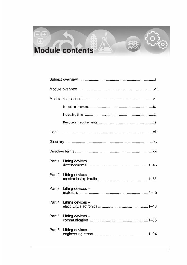
Module contents
Subject overview ................................................................................iii
Module overview................................................................................vii
Module components.......................................................................... vii
Module outcomes..................................................................... ix
Indicative time........................................................................... x
Resource requirements............................................................. xi
Icons ..............................................................................................xiii
Glossary ............................................................................................. xv
Directive terms.................................................................................xxi
Part 1: Lifting devices – developments ................................................................1–45
Part 2: Lifting devices – mechanics/hydraulics ................................................... 1–55
Part 3: Lifting devices – materials ......................................................................... 1–45
Part 4: Lifting devices – electricity/electronics .................................................... 1–43
Part 5: Lifting devices – communication .............................................................1–35
Part 6: Lifting devices – engineering report ......................................................... 1–24

7/31/2019 3 Lifting Devices
http://slidepdf.com/reader/full/3-lifting-devices 8/281
ii
Bibliography.......................................................................................25
Module evaluation.............................................................................27
7/31/2019 3 Lifting Devices
http://slidepdf.com/reader/full/3-lifting-devices 9/281
iii
Subject overview
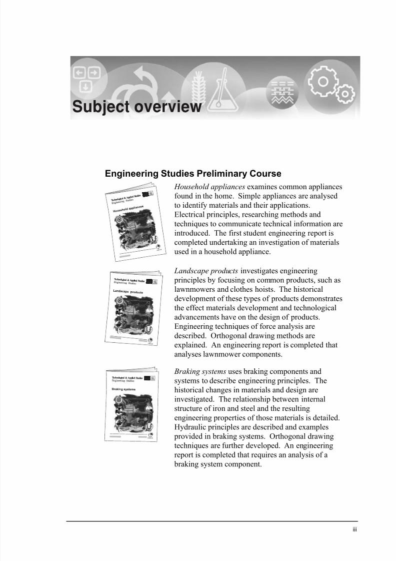
Engineering Studies Preliminary Course
Household appliances examines common appliances
found in the home. Simple appliances are analysedto identify materials and their applications.
Electrical principles, researching methods and
techniques to communicate technical information are
introduced. The first student engineering report is
completed undertaking an investigation of materials
used in a household appliance.
Landscape products investigates engineering
principles by focusing on common products, such as
lawnmowers and clothes hoists. The historical
development of these types of products demonstrates
the effect materials development and technological
advancements have on the design of products.
Engineering techniques of force analysis are
described. Orthogonal drawing methods are
explained. An engineering report is completed that
analyses lawnmower components.
Braking systems uses braking components and
systems to describe engineering principles. The
historical changes in materials and design areinvestigated. The relationship between internal
structure of iron and steel and the resulting
engineering properties of those materials is detailed.
Hydraulic principles are described and examples
provided in braking systems. Orthogonal drawing
techniques are further developed. An engineering
report is completed that requires an analysis of a
braking system component.

7/31/2019 3 Lifting Devices
http://slidepdf.com/reader/full/3-lifting-devices 10/281

7/31/2019 3 Lifting Devices
http://slidepdf.com/reader/full/3-lifting-devices 11/281

7/31/2019 3 Lifting Devices
http://slidepdf.com/reader/full/3-lifting-devices 12/281
vi
Aeronautical engineering explores the scope of the
aeronautical engineering profession. Career
opportunities are considered, as well as ethical
issues related to the profession. Technologiesunique to this engineering field are described.
Mechanical analyses includes aeronautical flight
principles and fluid mechanics. Materials and
material processes sections concentrate on their
application to aeronautics. The corrosion process is
explained and preventative techniques listed.
Communicating technical information using both
freehand and computer-aided drawing is required.
The engineering report is based on the aeronautical
profession, current projects and issues.
Telecommunications engineering examines the
history and impact on society of this field. Ethical
issues and current technologies are introduced.
The materials section concentrates on specialised
testing, copper and its alloys, semiconductors and
optical fibres. Electronic systems such as analogue
and digital are explained and an overview of a
variety of other technologies in this field is
presented. Analysis, related to telecommunication
products, is used to reinforce mechanical concepts.
Communicating technical information using both
freehand and computer-aided drawing is required.
The engineering report is based on the
telecommunication profession, current projects and
issues.
Figure 0.1 Modules

7/31/2019 3 Lifting Devices
http://slidepdf.com/reader/full/3-lifting-devices 13/281
vii
Module overview
Lifting devices investigates the social impact that these devices, from
complex cranes to simple car jacks, have had on our society. The
mechanical concepts are explained, including the hydraulic concepts
often used in lifting apparatus. The industrial processes used to form
metals and the processes used to control physical properties are
explained. Electrical requirements for many devices are detailed.
The technical rules for sectioned orthogonal drawings are demonstrated.
The engineering report is based on lifting devices.
Module components
Each module contains three components, the preliminary pages, the
teaching/learning section and additional resources.• The preliminary pages include:
– module contents
– subject overview
– module overview
– icons
– glossary
– directive terms.
Figure 0.2 Preliminary pages
7/31/2019 3 Lifting Devices
http://slidepdf.com/reader/full/3-lifting-devices 14/281
viii
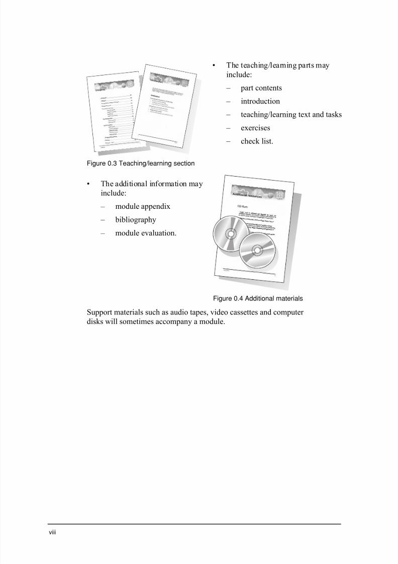
Figure 0.3 Teaching/learning section
• The teaching/learning parts may
include:
– part contents
– introduction
– teaching/learning text and tasks
– exercises
– check list.
• The additional information may
include:
– module appendix
– bibliography
– module evaluation.
Ad d it ional r esour ces
Figure 0.4 Additional materials
Support materials such as audio tapes, video cassettes and computer
disks will sometimes accompany a module.

7/31/2019 3 Lifting Devices
http://slidepdf.com/reader/full/3-lifting-devices 15/281
ix
Module outcomes
At the end of this module, you should be working towards being able to:
• differentiate between properties of materials and justify the selectionof materials, components and processes in engineering (H1.2)
• determine suitable properties, uses and applications of materials in
engineering (H2.1)
• demonstrate proficiency in the use of mathematical, scientific and
graphical methods to analyse and solve problems of engineering
practice (H3.1)
• use appropriate written, oral and presentation skills in the preparation
of detailed engineering reports (H3.2)
• investigate the extent of technological change in engineering (H4.1)
• apply a knowedge of history and technological change to
engineering-based problems (H4.2)
• appreciate social, environmental and cultural implications of
technological change in engineering and apply them to the anlaysis
of specific problems (H4.3)
• work individually and in teams to solve specific engineering
problems and in the preparation of engineering reports (H5.1)
• demonstrate skills in analysis, synthesis and experimentation related
to engineering (H6.2).
Extract from Stage 6 Engineering Studies Syllabus, © Board of Studies, NSW, 1999.
Refer to <http://www.boardofstudies.nsw.edu.au> for original and current documents.

7/31/2019 3 Lifting Devices
http://slidepdf.com/reader/full/3-lifting-devices 16/281
x
Indicative time
The Preliminary course is 120 hours (indicative time) and the HSC
course is 120 hours (indicative time).
The following table shows the approximate amount of time you should
spend on this module.
Preliminary modules Percentage of time Approximatenumber of hours
Household appliances 20% 24 hr
Landscape products 20% 24 hr
Braking systems 20% 24 hr
Bio-engineering 20% 24 hr
Elective: Irrigation systems 20% 24 hr
HSC modules Percentage of time Approximatenumber of hours
Civil structures 20% 24 hr
Personal and public transport 20% 24 hr
Lifting devices 20% 24 hr
Aeronautical engineering 20% 24 hr
Telecommunications engineering 20% 24 hr
There are five parts in Lifting devices. Each part will require about four
to five hours of work. You should aim to complete the module within 20
to 25 hours.

7/31/2019 3 Lifting Devices
http://slidepdf.com/reader/full/3-lifting-devices 17/281
xi
Resource requirements
During this module you will need to access a range of resources
including:• actual lifting devices to analyse
• technical drawing equipment
– drawing board, tee square, set squares (30∞ –60∞, 45∞),
protractor, pencils (0.5 mm mechanical pencil with B lead),
eraser, pair of compasses, pair of dividers
• calculator
• rule.

7/31/2019 3 Lifting Devices
http://slidepdf.com/reader/full/3-lifting-devices 18/281
xii

7/31/2019 3 Lifting Devices
http://slidepdf.com/reader/full/3-lifting-devices 19/281
xiii
Icons
As you work through this module you will see symbols known as icons.
The purpose of these icons is to gain your attention and to indicate
particular types of tasks you need to complete in this module.
The list below shows the icons and outlines the types of tasks for Stage 6
Engineering studies.
Computer
This icon indicates tasks such as researching using an
electronic database or calculating using a spreadsheet.
Danger
This icon indicates tasks which may present a danger and
to proceed with care.
Discuss
This icon indicates tasks such as discussing a point or
debating an issue.
Examine
This icon indicates tasks such as reading an article or
watching a video.
Hands on
This icon indicates tasks such as collecting data or conducting experiments.
Respond
This icon indicates the need to write a response or draw
an object.
Think
This icon indicates tasks such as reflecting on your
experience or picturing yourself in a situation.

7/31/2019 3 Lifting Devices
http://slidepdf.com/reader/full/3-lifting-devices 20/281
xiv
Return
This icon indicates exercises for you to return to your
teacher when you have completed the part. (OTEN OLP
students will need to refer to their Learner's Guide for instructions on which exercises to return).

7/31/2019 3 Lifting Devices
http://slidepdf.com/reader/full/3-lifting-devices 21/281
xv
Glossary
As you work through the module you will encounter a range of terms that
have specific meanings. The first time a term occurs in the text it will
appear in bold.
The list below explains the terms you will encounter in this module.
apparent weight difference between actual weight and buoyancyforce; weight it appears to be when submerged
austempering heat treatment process where the austenitised steelis soaked till the structure changes to ferrite andfinely dispersed carbide particles
bainite the product of austempering; ferrite with finelydispersed carbide particles
barelling formation of a shape often found in a ductilespecimen that has been subjected to a compressiveload
billet large ‘block’ of metal used as a start for the rolling process
boom (telescopic) telescopic member hinged to a revolving super-structure that can extend in length
bow’s notation labeling of spaces between applied forces on a non-concurrent force system
brinell type of hardness test that uses steel sphere indentorsand two different loads
brittleness a material that doesn't show much plasticdeformation is seen to be rigid and brittle; thestress/strain graphs for some ceramic materials areonly a straight line with no curve at all
buoyancy force upthrust force exerted by a fluid on a body equal tothe weight of the displaced fluid
centre of buoyancy the centre of mass of the displaced fluid. The buoyancy force acts through this point
centre of gravity a term used to describe the point that is the centrefor the mass of an object
7/31/2019 3 Lifting Devices
http://slidepdf.com/reader/full/3-lifting-devices 22/281
xvi
cherry picker a specialised crane consisting of an enclosed‘bucket’ in which workers are lifted to carry outtasks such as changing street lights etc
cold welding occurs under the extreme pressure of powder
forming when adjacent particles are forced to jointogether
compliance plate metal plate under the bonnet indicating details suchas the mass of a vehicle
compressibility A measure of the extent a fluid volume may bereduced by an increase in pressure
conventionalrepresentation
a shortened and easier method of drawing some partor feature, based upon AS 1100 drawing standards
core solid mixture of sand and resin used to create
shaped cavities inside cast structures.
coring occurs in alloys, under non equilibrium cooling,when the centre of the grain is richer in the higher melting point metal
counterweight weight used to supplement the weight of themachine in providing stability for lifting workingloads – usually attached to the rear of a revolvingsuper-structure
density mass per unit volume
derrick cranes small, simple, fixed cranes consisting of a boomand lifting tackle
derricking angular movement of crane main jib/boom in avertical plane, also called luffing
drum rotating cylinder with side flanges on which therope, used in the machine operation, is wrapped
ductility any stress/strain graph that shows a large area of plastic deformation and possibly a failure point thatis below the ultimate tensile strength (uts) isrepresentattive of a ductile material
elasticity the angle of the straight-line section of the stress-strain graph indicates elasticity; the steeper the line,the stiffer the material
elevators a moving cage or car used to lift people or cargofrom one level in a building to another
escalator a continuous, inclined moving walkway
factor of safety the margin included in all calculations to ensurematerials are not stressed beyond their elastic limit
fillet curve curve used in the design of cast and forgedcomponents to reduce stress concentration at corners
7/31/2019 3 Lifting Devices
http://slidepdf.com/reader/full/3-lifting-devices 23/281
xvii
fine pearlite thin bands of ferrite and cementite formed under faster than equilibrium cooling often found innormalising
fluid liquid or a gas
fly jib extension attached by pins and ropes to the boomhead to provide additional length for handlingspecified loads, it may also be offset from the lineof the boom
forklifts small motorised vehicles with two prongs or ‘forks’at the front designed to lift pallets
funicular polygon method of finding the line of action by adding‘strings’ to a space diagram
governor safety device, found on elevators, that operatesunder centrifugal force to activate emergency
brakes
hardenability the depth to which steel hardens
hydraulic operated by or employing water or other fluid
hydraulics study of pressurised liquid systems
item number a number assigned to a component on an assemblydrawing, used to identify components referred to ina materials or parts list
itemizing the use of numbers or upper case letters to identifycomponents on an assembly drawing
leader thin dark continuous lines drawn from an itemizingcircle or number to the component on an assemblydrawing
lifting motion of raising or lowering of load in a verticaldirection
lifting device a machine that makes it easier to raise somethingeither by reducing the force required or raising the
heights achievable
line of centres a line used to locate the point of contact of touchingcircles by joining the centres of the two circles
low carbon steel an alloy of iron with between 0.15% and 0.35%carbon
luffing angular movement of crane main jib/boom in avertical plane. Also called derricking
machinability the ability of a material to be shaped with variousmachine tools and cutting tips
7/31/2019 3 Lifting Devices
http://slidepdf.com/reader/full/3-lifting-devices 24/281
xviii
manometer gauge for measuring fluid pressure of gases or liquids
martempering heat treatment process where the austenitised steelis held till it is a constant temperature throughout
then quenched in water
mass quantity of matter in a substance
materials list a materials or parts list used on assembly drawingsto show item or part number, the name or description of the parts, the quantity required andthe material specification
non-concurrentforces
forces whose lines of action do not pass through acommon point
outrigger extendable or fixed arms attached to a mounting
base (chassis) which rest on supports at the outer ends to increase stability
patenting heat treatment process where the austenitised steelis cooled in molten lead
piezometer gauge for measuring fluid pressure of liquids
platform lifts any of a range of lifting devices consisting of a flatsurface on which a worker stands, and that may beraised or lowered
pneumatics study of pressurised air systems
prefinished surface finish, such as ‘Colorbonding’, that is plated on the surface before rolling
ram the piston that lifts on a hydraulic jack
ray a radial line from a pole point drawn to theend points of force vectors drawn on a forcediagram
relative density how heavy or light a substance is when comparedwith water
repeated features a regular pattern of features, such as holes or slots,in a component
resilience this is the area under the straight-line sectionof the stress/strain graph; it is a measure of the amount of energy which can be absorbed
by a material without causing plasticdeformation
resultant force single force having the same effect as the originalforce system
Rockwell type of hardness test that uses three different loads
and three different indentors
7/31/2019 3 Lifting Devices
http://slidepdf.com/reader/full/3-lifting-devices 25/281
xix
ropes twisted, multi strand steel cables used in elevatorsand cranes; also refers to twisted cables of naturalor synthetic fibres
sheave rotating wheel with an angled groove for carryingthe rope to operating position
slewing rotary motion of a crane about its vertical axis
space diagram a scaled drawing showing spaces between forcesacting on a body
specific gravity ratio of the density of the substance to the densityof water
specific volume volume per unit mass
strength the amount of force needed to plastically deform thematerial is called the proof or yield strength whilethe 'high point' of the stress/strain graph shows theultimate tensile strength
string lines drawn on funicular polygon to determine lineof action of resultant/equilibrant force. Drawn
parallel to rays on a force diagram
surface tension cohesive force that occurs at the surface of a liquid
tangency circles or arcs in contact with or touching a straightline
tangent a straight line which touches a circle or arc
telescopic extensioncrane
a crane in which the boom can be extended or shortened by retracting within itself
toughness the area under the total curve of the stress/straingraph; it is a measure of the amount of energyrequired to cause failure
tower crane a crane where the operator’s cabin, boom andlifting gear are supported at the top of a very talltower
vacuum gauge pressure below atmospheric pressure
Vickers type of hardness test that uses a standard load and adiamond pyramid indentor.
viscosity resistance to flow

7/31/2019 3 Lifting Devices
http://slidepdf.com/reader/full/3-lifting-devices 26/281
xx

7/31/2019 3 Lifting Devices
http://slidepdf.com/reader/full/3-lifting-devices 27/281
xxi
Directive terms
The list below explains key words you will encounter in assessment tasks
and examination questions.
account account for; state reasons for, report on;
give an account of; narrate a series of events or transactions
analyse identify components and the relationship between
the; draw out and relate implications
apply use, utilise, employ in a particular situation
appreciate make a judgement about the value of
assess make a judgement of value, quality, outcomes,
results or size
calculate ascertain/determine from given facts, figures or
information
clarify make clear or plain
classify arrange or include in classes/categories
compare show how things are similar or different
construct make, build, put together items or arguments
contrast show how things are different or opposite
critically
analyse/evaluate
add a degree or level of accuracy, depth,
knowledge and understanding, logic, questioning,
reflection and quality to analysis/evaluation
deduce draw conclusions
define state the meaning and identify essential qualities
demonstrate show by example

7/31/2019 3 Lifting Devices
http://slidepdf.com/reader/full/3-lifting-devices 28/281
xxii
describe provide characteristics and features
discuss identify issues and provide points for and/or against
distinguish recognise or note/indicate as being distinct or
different from; to note differences between
evaluate make a judgement based on criteria; determine the
value of
examine inquire into
explain relate cause and effect; make the relationships
between things evident; provide why and/or how
extract choose relevant and/or appropriate details
extrapolate infer from what is known
identify recognise and name
interpret draw meaning from
investigate plan, inquire into and draw conclusions about
justify support an argument or conclusion
outline sketch in general terms; indicate the main
features of
predict suggest what may happen based on available
information
propose put forward (for example a point of view, idea,
argument, suggestion) for consideration or action
recall present remembered ideas, facts or experiences
recommend provide reasons in favour
recount retell a series of events
summarise express, concisely, the relevant details
synthesise putting together various elements to make a whole
Extract from The New Higher School Certificate Assessment Support Document ,© Board of Studies, NSW, 1999.
Refer to <http://www.boardofstudies.nsw.edu.au> for original and current documents.

7/31/2019 3 Lifting Devices
http://slidepdf.com/reader/full/3-lifting-devices 29/281

7/31/2019 3 Lifting Devices
http://slidepdf.com/reader/full/3-lifting-devices 30/281
Arial Arial bold
Part 1: Lifting devices – developments 1
Part 1 contents
Introduction .........................................................................................2
What will you learn?........ ........ ......... ........ ........ ........ ........ ........ ...2
Lifting devices.....................................................................................3
Common lifting devices..............................................................5
Impact of lifting devices on construction methods......................26
Exercises...........................................................................................35
Progress check.................................................................................43
Exercise cover sheet.......................................................................45

7/31/2019 3 Lifting Devices
http://slidepdf.com/reader/full/3-lifting-devices 31/281
2 Lifting devices
Introduction
Welcome to the module on lifting devices.
Lifting devices are machines that have been designed to address two of the
major shortcomings of the human body – that of lack of strength and lack of
reach.
In this part you will look at the historical background behind the
development of a modern lifting device as well as considering the function of
a number of other common lifting devices. Finally you will examine the
influence lifting devices have had on the construction industry.
What will you learn?
You will learn about:
• the historical development of lifting devices
• engineering innovation in lifting devices and their effect on people’s
lives.
You will learn to:
• research the history of technological change in lifting devices
• examine the impact of lifting devices on engineering construction methods.
Extract from Stage 6 Engineering Studies Syllabus, © Board of Studies, NSW, 1999.
Refer to <http://www.boardofstudies.nsw.edu.au> for original and current documents.
7/31/2019 3 Lifting Devices
http://slidepdf.com/reader/full/3-lifting-devices 32/281
Arial Arial bold
Part 1: Lifting devices – developments 3
Lifting devices
What do you do if you need to lift something that is too heavy for you
to lift on your own?
You could get a group of friends together to give you a hand. That’s
exactly the technique used in many ancient civilisations except thefriends were called slaves. When blocks of stone weighing 2.5 tonnes
each had to be moved into position during the construction of the great
pyramids of Egypt, large teams of people using little more than brute
force were called upon for the job. A more modern solution is to use a
machine, some sort of lifting device, to help.
Machines are devices that help you do work. You would have learnt about
simple machines during the landscape and bio-engineering modules in the
preliminary year. Some machines such as bicycles are speed magnifiers
however the majority of machines are force magnifiers. That is, they have a
mechanical advantage of greater than one. The effort we apply at one partof the machine is not as great as the load we can lift at another part of the
machine.
Pulley systems, levers, hydraulic systems and screw threads are all
examples of simple machines that are used every day to magnify our force
and have been put to use in common lifting devices. A lifting device is a
machine that makes it easier for you to raise something that is difficult to lift
either because it is too heavy or too awkward to lift or in other cases
because the heights involved are beyond your physical capabilities.
Examples of common lifting devices include:
• corkscrews
• cranes
• car jacks and hoists
• elevators and escalators
• conveyor belts
• dry docks for ships
• forklifts
• pulley systems.

7/31/2019 3 Lifting Devices
http://slidepdf.com/reader/full/3-lifting-devices 33/281
4 Lifting devices
Look at the three common corkscrews in Figure 1.1. They all do the
same job – removing corks from wine bottles. They all have a screw
thread that winds down to get a good grip on the cork but after that they
all work in slightly different ways. The corkscrew on the left works on brute force but the other two are simple machines operating as force
magnifiers.
Figure 1.1 Three types of corkscrew
Explain how the middle and right hand corkscrews magnify the force
being applied to them.
___________________________________________________________
___________________________________________________________
___________________________________________________________
Did you answer?
Once the corkscrew has been wound into the cork the force applied by the user is magnified by a first order lever arrangement. The right-hand one is larger buteasier to use because two hands can apply the effort.
When you are looking at any lifting device for this module it is important to
keep in mind a number of important questions.
• What is being lifted and where?
• How is it doing it – what simple machine systems are being used?
• What materials have been used in the construction of the lifting device
and why?
7/31/2019 3 Lifting Devices
http://slidepdf.com/reader/full/3-lifting-devices 34/281
Arial Arial bold
Part 1: Lifting devices – developments 5
• What is the power source?
• What would you do if the lifting device was not available?
You will now go on to look at the development of a common lifting device –
the crane. The crane has been chosen because of its long history and thewide variety of designs that have been produced.
Common lifting devices
Cranes
Cranes are one of the bigger lifting devices you may see especially around
large construction sites. Scaled down cranes are mounted on the back of tow
trucks to lift one end of a vehicle so it can be towed away after an accident.
However, most cranes are used to lift things high off the ground, such as for
lifting materials to the upper floors of a building under construction. All
cranes are designed to lift a suspended load from one place to another.
Early cranes
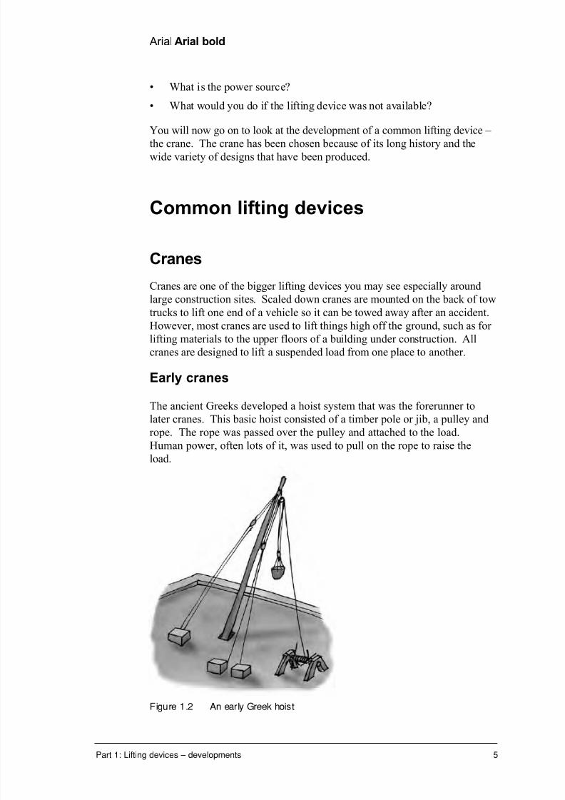
The ancient Greeks developed a hoist system that was the forerunner to
later cranes. This basic hoist consisted of a timber pole or jib, a pulley andrope. The rope was passed over the pulley and attached to the load.
Human power, often lots of it, was used to pull on the rope to raise the
load.
Figure 1.2 An early Greek hoist
7/31/2019 3 Lifting Devices
http://slidepdf.com/reader/full/3-lifting-devices 35/281
6 Lifting devices
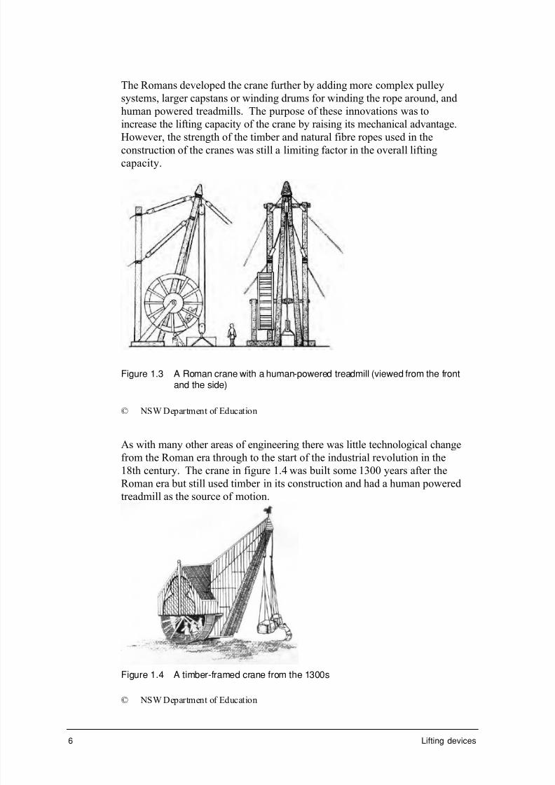
The Romans developed the crane further by adding more complex pulley
systems, larger capstans or winding drums for winding the rope around, and
human powered treadmills. The purpose of these innovations was to
increase the lifting capacity of the crane by raising its mechanical advantage.
However, the strength of the timber and natural fibre ropes used in theconstruction of the cranes was still a limiting factor in the overall lifting
capacity.
Figure 1.3 A Roman crane with a human-powered treadmill (viewed from the frontand the side)
© NSW Department of Education
As with many other areas of engineering there was little technological change
from the Roman era through to the start of the industrial revolution in the
18th century. The crane in figure 1.4 was built some 1300 years after the
Roman era but still used timber in its construction and had a human powered
treadmill as the source of motion.
Figure 1.4 A timber-framed crane from the 1300s
© NSW Department of Education
7/31/2019 3 Lifting Devices
http://slidepdf.com/reader/full/3-lifting-devices 36/281
Arial Arial bold
Part 1: Lifting devices – developments 7
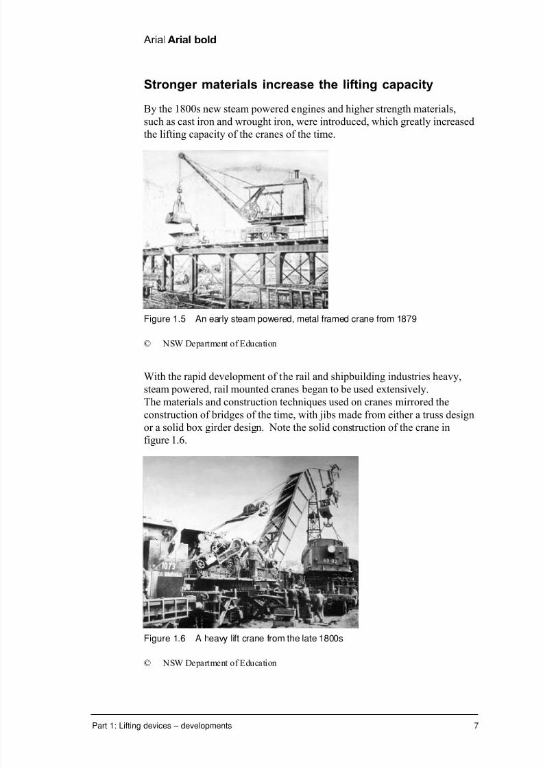
Stronger materials increase the lifting capacity
By the 1800s new steam powered engines and higher strength materials,
such as cast iron and wrought iron, were introduced, which greatly increased
the lifting capacity of the cranes of the time.
Figure 1.5 An early steam powered, metal framed crane from 1879
© NSW Department of Education
With the rapid development of the rail and shipbuilding industries heavy,
steam powered, rail mounted cranes began to be used extensively.
The materials and construction techniques used on cranes mirrored theconstruction of bridges of the time, with jibs made from either a truss design
or a solid box girder design. Note the solid construction of the crane in
figure 1.6.
Figure 1.6 A heavy lift crane from the late 1800s
© NSW Department of Education
7/31/2019 3 Lifting Devices
http://slidepdf.com/reader/full/3-lifting-devices 37/281
8 Lifting devices
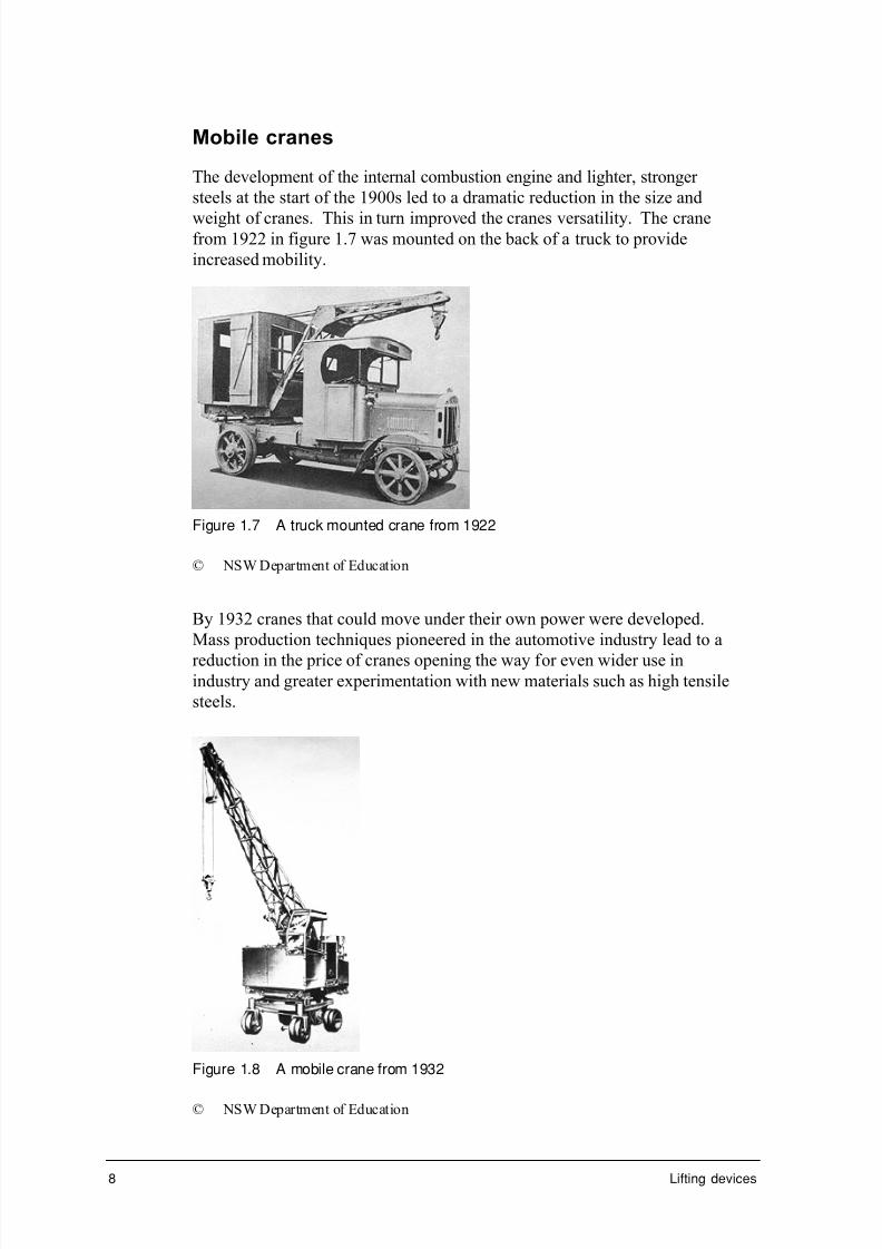
Mobile cranes
The development of the internal combustion engine and lighter, stronger
steels at the start of the 1900s led to a dramatic reduction in the size and
weight of cranes. This in turn improved the cranes versatility. The cranefrom 1922 in figure 1.7 was mounted on the back of a truck to provide
increased mobility.
Figure 1.7 A truck mounted crane from 1922
© NSW Department of Education
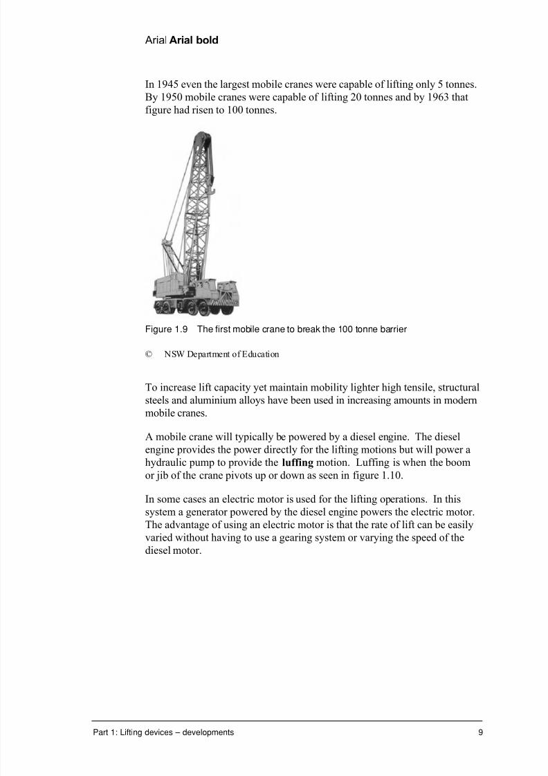
By 1932 cranes that could move under their own power were developed.
Mass production techniques pioneered in the automotive industry lead to a
reduction in the price of cranes opening the way for even wider use inindustry and greater experimentation with new materials such as high tensile
steels.
Figure 1.8 A mobile crane from 1932
© NSW Department of Education
7/31/2019 3 Lifting Devices
http://slidepdf.com/reader/full/3-lifting-devices 38/281
Arial Arial bold
Part 1: Lifting devices – developments 9
In 1945 even the largest mobile cranes were capable of lifting only 5 tonnes.
By 1950 mobile cranes were capable of lifting 20 tonnes and by 1963 that
figure had risen to 100 tonnes.
Figure 1.9 The first mobile crane to break the 100 tonne barrier
© NSW Department of Education
To increase lift capacity yet maintain mobility lighter high tensile, structural
steels and aluminium alloys have been used in increasing amounts in modern
mobile cranes.
A mobile crane will typically be powered by a diesel engine. The diesel
engine provides the power directly for the lifting motions but will power a
hydraulic pump to provide the luffing motion. Luffing is when the boom
or jib of the crane pivots up or down as seen in figure 1.10.
In some cases an electric motor is used for the lifting operations. In this
system a generator powered by the diesel engine powers the electric motor.
The advantage of using an electric motor is that the rate of lift can be easily
varied without having to use a gearing system or varying the speed of the
diesel motor.

7/31/2019 3 Lifting Devices
http://slidepdf.com/reader/full/3-lifting-devices 39/281
10 Lifting devices
Figure 1.10 A telescopic crane demonstrating luffing
© NSW Department of Education
Special purpose cranes
To this stage most cranes had developed along fairly similar lines but in the
1960s two new developments appeared. First was the development of
special purpose cranes.
One of the first purpose built cranes was designed to lift the inter-continental ballistic missiles of the USA defence force. Purpose built cranes are not as
common as multi-purpose machines because the more jobs a crane can do, the
more valuable it is to its owner/operator.
Figure 1.11 A special purpose crane designed to lift missiles
© NSW Department of Education

7/31/2019 3 Lifting Devices
http://slidepdf.com/reader/full/3-lifting-devices 40/281
Arial Arial bold
Part 1: Lifting devices – developments 11
What are the advantages of using a special purpose built crane for a
lifting operation?
___________________________________________________________
___________________________________________________________
___________________________________________________________
Did you answer?
It will do the job more quickly, more efficiently, more safely. These factorsmay combine to make its use less expensive also.
Two common examples of purpose built cranes are shown in figure 1.12 and
figure 1.13. Mobile container cranes are found at ports around Australia and
are capable of lifting 35 tonnes.
Figure 1.12 A special purpose crane designed to lift shipping containers
© NSW Department of Education
A crane designed to lift pallets of bricks from the back of a truck is another
example of a purpose built crane.

7/31/2019 3 Lifting Devices
http://slidepdf.com/reader/full/3-lifting-devices 41/281
12 Lifting devices
Figure 1.13 A special purpose crane designed to lift pallets of bricks
© NSW Department of Education
Telescopic extension cranes
The second major innovation in crane design from the 1960s was the
telescopic extension crane. Telescopic cranes have the advantage of being
able to work in confined spaces with the boom extending only as far as
needed. An early example from 1966 is seen in figure 1.14.
Telescopic cranes rely largely on the advantages of hydraulics for their
effectiveness. As you would already know from earlier modules, hydraulic
systems can smoothly transfer forces from one part of a machine to another and can be designed to act as force magnifiers. They also have high
efficiency ratings because there are few moving parts and friction is reduced
by using oil-based fluids. Modern telescopic cranes can reach to heights of
about 60 metres or further if a trussed jib is attached to the final boom
extension.
Figure 1.14 An early telescopic crane from 1966
© NSW Department of Education
Turn to the exercise section and complete exercise 1.1

7/31/2019 3 Lifting Devices
http://slidepdf.com/reader/full/3-lifting-devices 42/281
Arial Arial bold
Part 1: Lifting devices – developments 13
Tower cranes
A recent innovation is the self-erecting tower crane, as shown in figure
1.15. Tower cranes have very high towers or masts reaching unsupported
heights of 80 metres. Greater heights can be achieved if the mast is tied tothe frame of the building at regular intervals.
Figure 1.15 A tower crane tied to the building
© Tom Brown
Pretend you’re a self-erecting tower crane. Sit down on a chair. Place
your hands by your side onto the seat of the chair. Lift yourself up off
the seat and have someone place a book on the seat of the chair. When
you drop back down onto the chair you will be one book thickness
higher than you were before.
Tower cranes operate in a similar fashion. A climbing frame just below the
cabin uses large hydraulic rams to lift the cabin and jib one mast section
higher. The new mast section is lifted by the crane itself into the position
opened up by the climbing frame. Once the new section is bolted to the
lower portion of the mast the whole operation can continue upwards. When
the crane is no longer required it simply reverses the procedure to dismantle
itself.
Figure 1.16 shows the horizontal boom of a tower crane. On the left is the
hook and sling controlled by the trolley that moves back and forth along the
boom. On the right-hand side of the boom are heavy concrete blocks that
act as counterweights to the load. On the mast below the boom is the
operators cabin. Below the cabin is the climbing frame.

7/31/2019 3 Lifting Devices
http://slidepdf.com/reader/full/3-lifting-devices 43/281
14 Lifting devices
Figure 1.16 A self-supporting tower crane
Tower cranes do not have a high capacity with 20 tonnes being about the
maximum lift rating. Their main function is to move building materials
around the construction site especially to the upper floors of tall buildings.
Some tower cranes have horizontal jibs, which may reach 75 metres or more.This enables then to reach from one side of a building site to the other even
though the crane base remains stationary. When working at the extreme end
of the jib the lifting capacity is reduced by at least half due to the greater
turning effect placed on the crane by the load.
The use of modern radio telecommunication systems is vital to the operation
of a tower crane since in many cases the crane operator is not in direct visual
contact with the loading or unloading area. Their height and reach may even
allow them to lift materials over the top of a building under construction and
down the other side. This would not have been possible in the days prior to
two-way radio when a system of hand signals and whistles was used to passon messages to the crane operator. You may even have seen old photos or
film footage of workers, nicknamed ‘monkeys’, riding up with the load so
they could communicate more clearly with the crane operator. This unsafe
practice is no longer considered acceptable under current Occupational
Health and Safety regulations.
Most tower cranes use high capacity electric motors for their lifting power
source. As the cranes are fixed in position until they are dismantled they
can be wired into the electricity grid of the building. A typical tower crane
with a lift capacity of 20 tonnes would be powered by a 415 volt, 190
kilowatt motor.

7/31/2019 3 Lifting Devices
http://slidepdf.com/reader/full/3-lifting-devices 44/281
Arial Arial bold
Part 1: Lifting devices – developments 15
High capacity cranes
It has been pointed out that a mobile crane is generally more versatile than a
fixed or stationary crane but there are times when there is no substitute for
outright strength. Due to the high stresses involved, high capacity cranes areextremely large in size, fixed in position and require large counterweights to
balance the load.
The use of high capacity cranes is limited because of their high cost and lack
of mobility. The hammerhead crane in figure 1.17 was capable of lifting 250
tonnes – that’s about 160 family-size cars in one go. This crane was used at
the Garden Island naval dockyards in Sydney to lift major machinery
components, missile launchers, ship superstructures and even complete
ships out of the water. Due to its age it requires expensive maintenance
work and has not been used since the early 1990s.
Figure 1.17 The Hammerhead crane at Sydney’s Garden Island dockyards
© NSW Department of Education
Lifting materials twenty storeys to the top of a building with a tower crane
is a different problem from lifting people twenty storeys to the top of a
building. You will now look briefly at a number of other common lifting
devices.
Turn to the exercise section and complete exercise 1.2

7/31/2019 3 Lifting Devices
http://slidepdf.com/reader/full/3-lifting-devices 45/281
16 Lifting devices
Car jacks and hoists
In Personal and public transport you discovered how important the
motorcar is to everyday living for many people. The engine lift, trolley jack,
car hoist, block and tackle and the simple car jack are all lifting devices thatare associated with the motorcar. There are scissor type-jacks, screw thread
jacks, ratchet type jacks and multi-lift hydraulic jacks. A jack for off road
vehicles has been developed to allow the vehicle to be lifted out of bogs, or
lifted over uneven territory which uses a PVC coated cushion that is inflated
by connecting a tube to the exhaust pipe. Modern racing cars have a jack
built into the frame that is activated by compressed air in the pits to achieve
speed in the lifting operation.
The simple car jack is designed to raise one corner of a car when changing a
wheel. All cars come with their own jack and extreme care must be taken if
using a jack borrowed from another vehicle, as the head of the jack will need
to mate with the designated jacking point under the car.
Always use a jack on firm, level ground and never work under a car
supported only on a car jack.
Since they rely on human effort for the power source car jacks are designed
to have a very high mechanical advantage provided by the screw thread.
Mechanical jacks such as these deliberately have low efficiency ratings so
that the weight of the vehicle won’t force the jack to unwind once the effort
has stopped.
Figure 1.18 A typical car jack from a small modern car

7/31/2019 3 Lifting Devices
http://slidepdf.com/reader/full/3-lifting-devices 46/281
Arial Arial bold
Part 1: Lifting devices – developments 17
Figure 1.18 shows a common car jack from a small car rated to lift 850
kilograms. Due to its design, this jack has a variable mechanical advantage.
When first raising the jack, the mechanical advantage is low meaning the jack
will gain height quickly. By the time it is at the height where the load would
normally be applied the mechanical advantage has increased, reducing therate at which the jack gains height but also reducing the effort required to lift
the car.
Look at a car jack and see it differs to the one in figure 1.18.
How could you work out its velocity ratio, mechanical advantage and
efficiency?
A trolley jack is a hydraulically operated jack of high capacity capable of lifting one end of a vehicle off the ground. It is used by mechanics to make
quick inspections under a vehicle. Again never work under a vehicle
supported only by a trolley jack.
The engine lift is a mobile block and tackle system that can be wheeled over
to the vehicle to enable the motor to be lifted and removed from the engine
bay. Most auto workshops will also have a fixed block and tackle mounted
to a strong roofing beam for the same purpose.
To work under a vehicle safely the car hoist is used. The hoist in figure 1.19
is an electrically operated hydraulic system capable of lifting 2 500 kg.

7/31/2019 3 Lifting Devices
http://slidepdf.com/reader/full/3-lifting-devices 47/281
18 Lifting devices
Figure 1.19 Car hoists enable mechanics to work safely under vehicles
Turn to the exercise section and complete exercise 1.3.
Lifting people
When lifting machinery, vehicles or building materials a certain degree of
disregard for the cargo is acceptable but when lifting live cargo, such as
people, the rules change dramatically. Much greater emphasis must be
placed on the needs of the cargo particularly the need for a quick, safe and
comfortable journey.
There are four general types of people lifts:
• elevators
• escalators
• moving ramps and walkways• specialised working platforms.

7/31/2019 3 Lifting Devices
http://slidepdf.com/reader/full/3-lifting-devices 48/281
Arial Arial bold
Part 1: Lifting devices – developments 19
Elevators
Elevators, more commonly known in Australia as lifts, are small rooms,
called cars, which travel up and down an elevator shaft. Elevators are
designed to move people and materials from floor to floor in multi-storey buildings. Buildings over three storeys are required to have at least one
elevator. Large buildings will have banks of elevators with some being
dedicated to special tasks. In hospitals for example, some elevators are
dedicated to moving patients between the hospital wards and the operating
theatres while others are reserved for the cleaning staff for waste disposal
and linen transfer.
Why would a hospital have a system of dedicated elevators for specific
tasks? Can you think of any other specialised or dedicated elevators you
may have seen or heard about in other types of buildings?
When designing an elevator system a number of factors need to be taken into
account such as the:
• type of building
• number of floors to be serviced
• floor to floor distance
• number of people using each floor
• maximum peak demand
• load to be moved.
There are two general types of elevator systems:
• electric
• hydraulic.
Electric lifts are the most common type and can be adapted to be used in all
situations. The motors for an electric lift are usually:
• two speed AC motors for car speeds up to 1.0 m/s
• variable speed AC or DC geared motors for speeds up to 2.5 m/s
• direct drive DC or variable speed AC gearless motors for speeds greater
than 2.5 m/s.
Despite common fears of being trapped in an elevator or of the elevator
cables snapping, statistically it is safer to use a lift than to take the stairs.
Elevators have more than one cable to provide greater safety and all have
emergency brakes to slow the car if the cables suddenly snapped. The first
elevators to have an emergency brake were designed by Elisha Otis way
back in 1853. The early elevators designed by Otis were built to carryfreight but in 1856 he developed a ‘vertical railway’ passenger lift.

7/31/2019 3 Lifting Devices
http://slidepdf.com/reader/full/3-lifting-devices 49/281
20 Lifting devices
Around the early 1890s multi-strand steel cables replaced hemp rope for the
elevator cables improving their safety and efficiency. Early elevators used a
top mounted electric motor turning a winding drum with the elevator cable
simply wound around the drum. As the height of the buildings increased, so
did the length of the cable required. This lead to problems with the cable notwinding neatly onto the drum.
Have you had the same problem with your garden hose?
The solution that was developed, and which is still used today, was to have
the electric motor winding a number of high tensile cables to raise and lower
the elevator. One end of each cable is attached to the top of the elevator car
and is then wrapped around the drive shaft – a grooved pulley. The other
ends are attached to a counterweight that slides up and down the shaft on its
own rails. The counterweight, equal to the weight of the car with a half load
of passengers, reduces the effort required from the motor and provides
enough friction at the drive shaft for the cables not to slip. Sailors use a
similar principle on the winch systems on sailing ships.
Winding drum
Elevator car
Elevator shaft
Counterweight
Electric motor
Figure 1.20 Components of a typical electric elevator
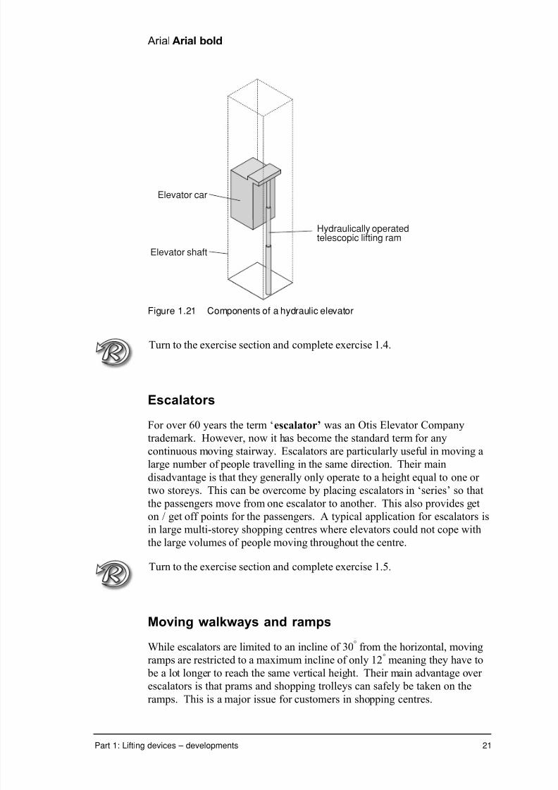
Hydraulic elevators are used extensively in low-rise buildings up to five
storeys and where elevator speeds do not exceed 0.75 m/s. The elevator is
pushed up the elevator shaft by a hydraulically controlled piston. To save
space a telescopic piston may be used. Hydraulic elevators do not require
any overhead mounted lifting gear. The pumping unit can be located up to
15 metres away from the shaft and the overall installation and running costs
are less than for an electric drive system.
7/31/2019 3 Lifting Devices
http://slidepdf.com/reader/full/3-lifting-devices 50/281
Arial Arial bold
Part 1: Lifting devices – developments 21
Elevator car
Elevator shaft
Hydraulically operatedtelescopic lifting ram
Figure 1.21 Components of a hydraulic elevator
Turn to the exercise section and complete exercise 1.4.
Escalators
For over 60 years the term ‘escalator’ was an Otis Elevator Company
trademark. However, now it has become the standard term for any
continuous moving stairway. Escalators are particularly useful in moving a
large number of people travelling in the same direction. Their main
disadvantage is that they generally only operate to a height equal to one or
two storeys. This can be overcome by placing escalators in ‘series’ so that
the passengers move from one escalator to another. This also provides get
on / get off points for the passengers. A typical application for escalators is
in large multi-storey shopping centres where elevators could not cope with
the large volumes of people moving throughout the centre.
Turn to the exercise section and complete exercise 1.5.
Moving walkways and ramps
While escalators are limited to an incline of 30° from the horizontal, moving
ramps are restricted to a maximum incline of only 12° meaning they have to
be a lot longer to reach the same vertical height. Their main advantage over
escalators is that prams and shopping trolleys can safely be taken on the
ramps. This is a major issue for customers in shopping centres.

7/31/2019 3 Lifting Devices
http://slidepdf.com/reader/full/3-lifting-devices 51/281
22 Lifting devices
Specialised working platforms
When carrying out work high above the ground workers face two major
problems:
• getting up to the operating height quickly and with minimum effort
• being able to move freely and work safely while high off the ground.
Devices such as cherry pickers and scissor lifts provide much greater safety
than using older technology such as working from a ladder. Ladder work is
considered so dangerous that there are now strict guidelines relating to their
use in the workplace. A cherry picker can also be considered as another
example of a specialised crane.
An example of a specialised working platform is shown in figure 1.22

7/31/2019 3 Lifting Devices
http://slidepdf.com/reader/full/3-lifting-devices 52/281

7/31/2019 3 Lifting Devices
http://slidepdf.com/reader/full/3-lifting-devices 53/281
24 Lifting devices
Dry dock
Up until now you have been looking at the lifting of small to medium sized
objects but how could you lift a large ocean-going ship out of the water to
carry out repairs. One solution is to use a floating dock such as the one at Newcastle, shown in figure 1.23. The floating dock is a long ‘U’ shaped
channel structure, which is partially sunk by flooding the ballast tanks in its
hold. The ship to be repaired is sailed into position inside the dock and
propped against the sides to stop it from falling over. The floating dock is
then raised by pumping out the tanks and filling them with air. The ship is
lifted out of the water at the same time as the dock is raised. The floating
dock in Newcastle can handle ships weighing up to 45 000 tonne.
Figure 1.23 The floating dock at Newcastle
Helicopters
Using helicopters as a lifting device is an example of a new application being
found for an existing machine. Basically thought of as a form of air transport, helicopters play a small but increasing role in the lifting and
transferring of cargo.
Helicopters have a significant advantage over other forms of lifting device.
They are fast, highly mobile and most importantly can access areas
inaccessible by other forms of transport. Some heavy lift models such as
the Russian MI-26 have a lifting capacity of up to 20 tonnes.
7/31/2019 3 Lifting Devices
http://slidepdf.com/reader/full/3-lifting-devices 54/281
Arial Arial bold
Part 1: Lifting devices – developments 25
Some of the varying lifting applications helicopters have been used for
include :
• winching bushwalkers hurt or trapped in rugged bushland
• rescuing sailors at sea• water bombing bush fires
• lifting and transporting cargo to remote locations
• moving large animals, such as an elephant or rhinoceros out of
inaccessible terrain for the purpose of relocation.
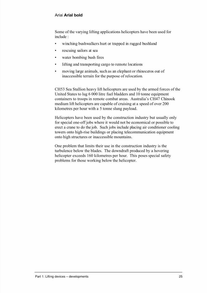
CH53 Sea Stallion heavy lift helicopters are used by the armed forces of the
United States to lug 6 000 litre fuel bladders and 10 tonne equipment
containers to troops in remote combat areas. Australia’s CH47 Chinook
medium lift helicopters are capable of cruising at a speed of over 200kilometres per hour with a 5 tonne slung payload.
Helicopters have been used by the construction industry but usually only
for special one-off jobs where it would not be economical or possible to
erect a crane to do the job. Such jobs include placing air conditioner cooling
towers onto high-rise buildings or placing telecommunication equipment
onto high structures or inaccessible mountains.
One problem that limits their use in the construction industry is the
turbulence below the blades. The downdraft produced by a hovering
helicopter exceeds 160 kilometres per hour. This poses special safety
problems for those working below the helicopter.

7/31/2019 3 Lifting Devices
http://slidepdf.com/reader/full/3-lifting-devices 55/281
26 Lifting devices
Impact of lifting devices on constructionmethods
In this section of the module it is important to consider a number of issues.
• Has a change in lifting device impacted on the type of buildings being
constructed?
• Has the building style remained the same but the method of
construction changed due to the use of new lifting devices?
• How have lifting devices improved safety and productivity in the
construction industry?
In 1871 a huge fire devastated much of the central business district of the
large American city of Chicago. The building boom that followed resulted inthe price of land skyrocketing. The best way to make use of the valuable
land was to build as tall a building as possible.
At this same time a new innovative building system was being trialled
utilising the increased strength of a new material – steel. The new system
relied on the weight of the building being supported by a steel skeleton
instead of the outer masonry walls. These early ‘skyscrapers’ quickly
exceeded the height of the buildings they replaced. One New York building
constructed at the time using the old technique of load bearing walls required
walls three metres thick at the base to support the fourteen-storey structure.
There were two problems that needed to be overcome before architects
could take full advantage of the steel frame building system.
• How to get the materials to the upper floors of the building under
construction.
• How to move people through the building once it had been constructed.
The role of cranes in multi-storey construction
There has always been a need for lifting devices on construction sites. The
challenge for engineers now is how to cope with the increased heights of
modern buildings while at the same time maintaining safe working
procedures and reducing construction times.
On modern multi-storey buildings that use a steel frame, curtain wall
construction method, the steel frame is constructed as soon as the
foundation work is complete. Tall tower cranes and derrick cranes are used
to lift the steel beams and hold them in place until secured. Derrick cranes
are small, fixed, basic cranes similar to the simple Egyptian hoist with safe
working loads of approximately 5 tonnes. They may be assembled on thetop floor of a building under construction. The derrick crane can jack itself

7/31/2019 3 Lifting Devices
http://slidepdf.com/reader/full/3-lifting-devices 56/281
Arial Arial bold
Part 1: Lifting devices – developments 27
up to the next level as the building grows in height in a manner similar to that
used by tower cranes. Tower cranes working at extreme heights are ‘tied’ to
the frame of the building to stop the mast from buckling by increasing the
rigidity of the mast.
The walls of steel-framed buildings take very little of the load with their
main function being to close in and protect the building. This is one reason
why modern buildings can have such large expanses of glass windows – the
outer skin is not required to take any weight. It also means that the walls
and windows can be fitted out anytime during the construction process.
The walls of the lower levels don’t need to be in place before work can begin
on the upper levels. Lightweight, pre-fabricated panels are lifted into
position by crane to be bolted or clipped to the supporting frame.
Sections of the walls are deliberately left unfilled to allow the loading and
unloading of materials to the various levels of the building under construction. Loading decks fitted into the vacant spots have been designed
to improve productivity and safety by providing secure platforms for the
cranes to load to, while also providing overhead protection to those working
below. The decks can be retracted when not required so that they don’t
obstruct the rope and load of cranes working in the area.
Figure 1.24 Loading from a crane to a retractable deck
© Preston Australia P/L
When construction has finished, tower cranes can simply disassemble their
mast one section at a time to lower themselves back to street level.
A second method is to use a derrick crane on top of the building to lower the
tower crane. The derrick crane is then completely dismantled and may belowered by a temporary block and tackle system.

7/31/2019 3 Lifting Devices
http://slidepdf.com/reader/full/3-lifting-devices 57/281

7/31/2019 3 Lifting Devices
http://slidepdf.com/reader/full/3-lifting-devices 58/281
Arial Arial bold
Part 1: Lifting devices – developments 29
Turn to the exercise section and complete exercise 1.6.
Safety considerations
Lifting devices contribute to improved safety in a number of ways. On a
simplistic level, by reducing the human effort required, they greatly reduce
the chance of back injury, one of the biggest forms of injury amongst
construction workers.
Lifting devices such as cherry pickers and platform hoists provide a more
secure working environment for people working high off the ground.
Figure 1.25 A worker using a cherry picker to inspect street lighting
Also, the curtain wall system of modern multi-storey buildings allows
sections of the wall to remain unfilled during construction to allow access to
the building for delivery of materials and for personnel elevators. These
temporary elevators are a quicker and safer way of moving workers, light
materials and equipment up and down the building during construction.
They free up the cranes for tasks requiring greater lifting capacity.
Properly designed guards and barriers reduce the chance of building materials
falling or being dropped to the ground when using temporary elevatorsimproving the safety for those working below on the construction site. As

7/31/2019 3 Lifting Devices
http://slidepdf.com/reader/full/3-lifting-devices 59/281
30 Lifting devices
with tower cranes the temporary elevators are tied to the framework of the
building to provide greater rigidity. The blank portions of wall are filled in
once the elevator is dismantled.
The lower levels of multi-storey buildings are now usually surrounded byscaffolding and a shade cloth type material to improve the conditions inside
the building under construction by
• stopping swirling wind from stirring up dust
• reducing the chance of tools, equipment and materials being dropped to
lower levels
• providing a visual barrier to stop workers from walking off the upper
levels of the building.
The design and construction of this scaffolding needs to be co-ordinated
with the operating requirements of the cranes, their loading decks and the
temporary elevators that will be working on the site.
Turn to the exercise section and complete exercise 1.7.
Storage of building materials
An ever-increasing range of building materials are being bundled together to
enable them to be stored on pallets or specialised racks. By using forklifts
and platform lifts, hardware and building supply companies can stack their
materials as high as 10 metres off the ground yet still be able to retrieve them
quickly when required. For hardware stores and their customers this has led
to a number of improvements such as:
• a greater range of items can be stored
• materials can be retrieved more quickly – less waiting time
• a warehouse space can hold a greater amount of stored material.
Forklifts and walk-behind pallet lifts are designed to work in narrowwarehouse aisles. One innovation allows a machine to pivot on its own
footprint using a system whereby the driving wheels are controlled
independently to the point where they turn in opposite directions when
maximum manoeuvrability is required.

7/31/2019 3 Lifting Devices
http://slidepdf.com/reader/full/3-lifting-devices 60/281
Arial Arial bold
Part 1: Lifting devices – developments 31
Direction of motion
Wheel direction
Figure 1.26 Varying the direction of travel of the driving wheels of a forklift
To reduce the levels of harmful exhaust gases and noise most indoor-based
forklift models operate using battery powered electric motors. Outdoor
forklifts are likely to use Liquid Petroleum Gas (LPG) or small traditional
petrol engines.
Figure 1.27 A modern petrol powered forklift

7/31/2019 3 Lifting Devices
http://slidepdf.com/reader/full/3-lifting-devices 61/281
32 Lifting devices
Safety features common on most modern forklifts include:
• very low centre of gravity to increase stability
• guards to protect the operator from falling objects
• reduced noise levels from the motor
• ergonomically designed controls and seats to reduce operator fatigue
• sprung floors on operator stand-up models
• warning buzzer when reversing.
Lifting devices found on domestic constructionsites
On a domestic building site a number of lifting devices are commonly used.
Forklifts are used to unload palletised materials from the delivery trucks to a
convenient location on site.
Bobcats and front-end loaders are used to lift and carry loose materials such
as sand, soil and gravel.
Pallet cranes are specialised truck mounted cranes used to unload palletised
materials off the truck.
Conveyor belts are used in situations such as to carry tiles to the roof. With
one person loading and two others unloading on the roof the complete roof
of a typical house can be stacked in about two hours. The same job without
the conveyor belts would take the same workers about eight hours. It would
also be significantly more dangerous and demanding, as the workers would
have to carry the tiles up ladders or ramps to the roof.

7/31/2019 3 Lifting Devices
http://slidepdf.com/reader/full/3-lifting-devices 62/281

7/31/2019 3 Lifting Devices
http://slidepdf.com/reader/full/3-lifting-devices 63/281
34 Lifting devices

7/31/2019 3 Lifting Devices
http://slidepdf.com/reader/full/3-lifting-devices 64/281
Arial Arial bold
Part 1: Lifting devices – developments 35
Exercises
Exercise 1.1
Explain how each of the following developments in crane design from the
1960s has had a positive impact on lifting efficiency and/or safety.a Specialised cranes
_______________________________________________________
_______________________________________________________
_______________________________________________________
_______________________________________________________
_______________________________________________________
_______________________________________________________
_______________________________________________________
_______________________________________________________
_______________________________________________________
b Telescopic extension cranes
_______________________________________________________
_______________________________________________________
_______________________________________________________
_______________________________________________________
_______________________________________________________
_______________________________________________________
_______________________________________________________

7/31/2019 3 Lifting Devices
http://slidepdf.com/reader/full/3-lifting-devices 65/281
36 Lifting devices
Exercise 1.2
Over the past 100 years the relative size and weight of cranes has decreased
compared to their lifting capacity. List four reasons for this decrease in
relative size.a _______________________________________________________
b _______________________________________________________
c _______________________________________________________
d _______________________________________________________
Exercise 1.3
Compare two different lifting devices by completing the table below.
Lifting device No.1 Lifting device No. 2
Type of lifting device(Name of device)
Purpose(What does the devicehave to lift)
Lifting capacity(What is the maximumload it can lift)
Power source(Human power,electric, petrol, orsomething else – specify)
Safety features
(Load limiting sensors,guards, Governmentregulation)
Who would use it(Builder, car mechanic,etc)
Simple machinesystems used(screw thread, pulleys,levers, hydraulics)

7/31/2019 3 Lifting Devices
http://slidepdf.com/reader/full/3-lifting-devices 66/281
Arial Arial bold
Part 1: Lifting devices – developments 37
Exercise 1.4
The elevator system for a public building such as a hospital would be
different to the elevator system in a similar sized commercial building.
Identify and describe two main features in the elevator systems in the two
buildings.
a Hospital
i ___________________________________________________
___________________________________________________
ii ___________________________________________________
___________________________________________________
b Commercial building
i ___________________________________________________
___________________________________________________
ii ___________________________________________________
___________________________________________________
Exercise 1.5
a Explain why escalators are more efficient than elevators in moving
people from floor to floor in large shopping centres.
_______________________________________________________
_______________________________________________________
_______________________________________________________
_______________________________________________________
b Explain why escalators aren’t used more widely in other types of
buildings by highlighting two of the main restrictions of escalators.
_______________________________________________________
_______________________________________________________
_______________________________________________________
_______________________________________________________

7/31/2019 3 Lifting Devices
http://slidepdf.com/reader/full/3-lifting-devices 67/281
38 Lifting devices
Exercise 1.6
‘Tall multi-storey buildings could not exist without the elevator.’
Explain this statement making reference to the ways that elevators have
made multi-storey buildings more accessible.
__________________________________________________________
__________________________________________________________
__________________________________________________________
__________________________________________________________
__________________________________________________________
__________________________________________________________
__________________________________________________________
__________________________________________________________
__________________________________________________________
__________________________________________________________
Exercise 1.7
Describe three ways in which modern lifting devices have improved safety
on construction sites.
1 _________________________________________________________
2 _________________________________________________________
3 _________________________________________________________
Exercise 1.8
List five criteria you would use when deciding on the appropriateness of a
lifting device for a particular task.
__________________________________________________________
__________________________________________________________
__________________________________________________________
__________________________________________________________
__________________________________________________________

7/31/2019 3 Lifting Devices
http://slidepdf.com/reader/full/3-lifting-devices 68/281
Arial Arial bold
Part 1: Lifting devices – developments 39
Exercise 1.9
Describe the impact lifting devices have had on construction time and
building height on modern building sites. Give examples to support your
answer.a Construction time
_______________________________________________________
_______________________________________________________
_______________________________________________________
_______________________________________________________
_______________________________________________________
b Building height
_______________________________________________________
_______________________________________________________
_______________________________________________________
_______________________________________________________
_______________________________________________________
Exercise 1.10
Select the alternative a, b, c, or d that best completes the statement. Circle
the letter.
1 Lifting devices usually have:
a a velocity ratio greater than one and a mechanical advantage less
than one
b a velocity ratio less than one and a mechanical advantage greater
than one
c a velocity ratio and mechanical advantage both greater than one
d a velocity ratio and mechanical advantage both less than one.
2 People use lifting devices because:
a the human body is not very strong or tall
b it saves time and money
c they might hurt their back if they don’t use one
d all of the above

7/31/2019 3 Lifting Devices
http://slidepdf.com/reader/full/3-lifting-devices 69/281
40 Lifting devices
3 The only power source not still commonly used in lifting devices today is:
a human power
b electric power
c petrol power
d steam power.
4 In the period after the Roman era the development of lifting devices did
not progress greatly because:
a the power source did not change
b the materials technology did not improve
c there was no need for an improved lifting device until multi-storey
buildings were designed
d slaves were available to do all the lifting.
5 A specific advantage of telescopic cranes is that:
a they can lift large loads
b they can work in restricted spaces
c they can reach high off the ground
d they are very mobile.
6 Car jacks have low efficiencies because:
a it stops them from winding down under load
b it stops them from costing too much
c they are only small
d they are human powered.
7 The maximum acceleration rate of an elevator is limited by:
a the strength of the elevator cables
b the power of the driving motor
c the effect on the human body
d the stopping power of the elevator braking system.
8 Tower cranes do not have a high lifting capacity because:
a the mast is too thin to support a large load
b electric motors can’t lift large loads
c the counter-weights required to balance the load would be too large
d there is not the demand to lift high capacity loads on a building site.

7/31/2019 3 Lifting Devices
http://slidepdf.com/reader/full/3-lifting-devices 70/281

7/31/2019 3 Lifting Devices
http://slidepdf.com/reader/full/3-lifting-devices 71/281
42 Lifting devices

7/31/2019 3 Lifting Devices
http://slidepdf.com/reader/full/3-lifting-devices 72/281
Arial Arial bold
Part 1: Lifting devices – developments 43
Progress check
During this part you examined the development of the crane as a lifting
device and were introduced to other common lifting devices such as
corkscrews, elevators and forklifts.
Take a few moments to reflect on your learning then tick the box which best represents your level of achievement.
❏✓ Agree – well done
❏✓ Disagree – revise your work
❏✓ Uncertain – contact your teacher A g r e e
D i s a g r e e
U n c e r t a i n
I have learnt about:
• the historical development of lifting devices
• engineering innovation in lifting devices and theireffect on people’s lives.
I have learnt to:
• research the history of technological change in liftingdevices
• examine the impact of lifting devices on engineeringconstruction methods.
Extract from Stage 6 Engineering Studies Syllabus, © Board of Studies, NSW, 1999.
Refer to <http://www.boardofstudies.nsw.edu.au> for original and current documents.
During the next part you will investigate how engineering mechanics and
hydraulics can be used to solve problems relating to some lifting devices.

7/31/2019 3 Lifting Devices
http://slidepdf.com/reader/full/3-lifting-devices 73/281

7/31/2019 3 Lifting Devices
http://slidepdf.com/reader/full/3-lifting-devices 74/281
Arial Arial bold
Part 1: Lifting devices – developments 45
Exercise cover sheet
Exercises 1.1 to 1.10 Name: ______________________________
Check!
Have you have completed the following exercises?
❒ Exercise 1.1
❒ Exercise 1.2
❒ Exercise 1.3
❒ Exercise 1.4
❒ Exercise 1.5
❒Exercise 1.6
❒ Exercise 1.7
❒ Exercise 1.8
❒ Exercise 1.9
❒ Exercise 1.10
Locate and complete any outstanding exercises then attach your responses
to this sheet.
If you study Stage 6 Engineering Studies through a Distance Education
Centre/School (DEC) you will need to return the exercise sheet and your
responses as you complete each part of the module.
If you study Stage 6 Engineering Studies through the OTEN Open Learning
Program (OLP) refer to the Learner’s Guide to determine which exercises
you need to return to your teacher along with the Mark Record Slip.

7/31/2019 3 Lifting Devices
http://slidepdf.com/reader/full/3-lifting-devices 75/281

7/31/2019 3 Lifting Devices
http://slidepdf.com/reader/full/3-lifting-devices 76/281

7/31/2019 3 Lifting Devices
http://slidepdf.com/reader/full/3-lifting-devices 77/281

7/31/2019 3 Lifting Devices
http://slidepdf.com/reader/full/3-lifting-devices 78/281
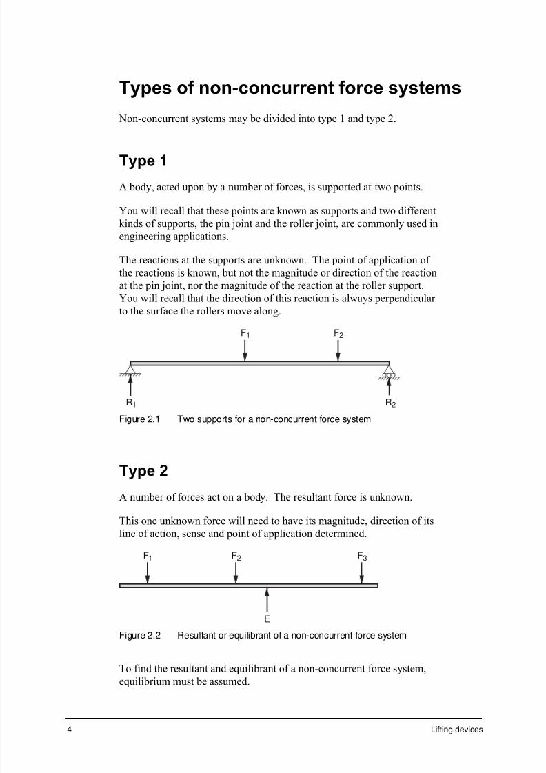
7/31/2019 3 Lifting Devices
http://slidepdf.com/reader/full/3-lifting-devices 79/281
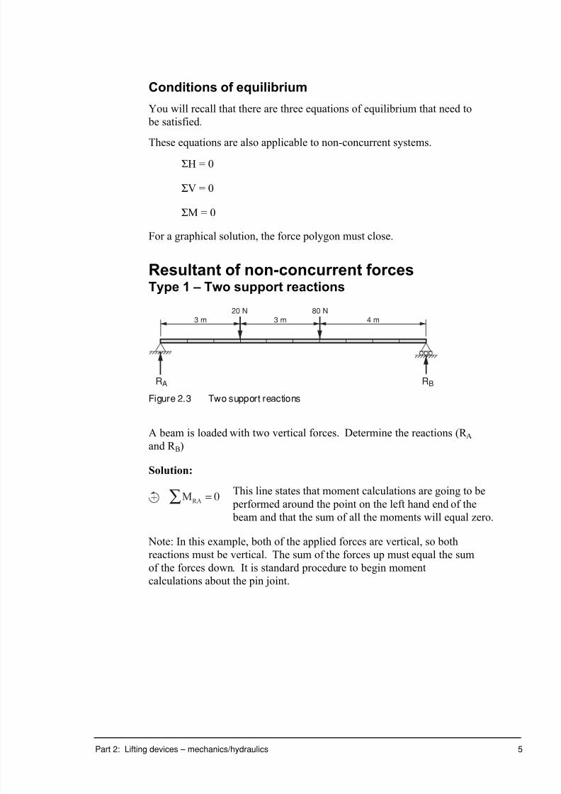
7/31/2019 3 Lifting Devices
http://slidepdf.com/reader/full/3-lifting-devices 80/281
Part 2: Lifting devices – mechanics/hydraulics 5
Conditions of equilibrium
You will recall that there are three equations of equilibrium that need to
be satisfied.
These equations are also applicable to non-concurrent systems.
SH = 0
SV = 0
SM = 0
For a graphical solution, the force polygon must close.
Resultant of non-concurrent forcesType 1 – Two support reactions
20 N
RA RB
80 N3 m 3 m 4 m
Figure 2.3 Two support reactions
A beam is loaded with two vertical forces. Determine the reactions (R Aand R B)
Solution:
MRA
= 0Â This line states that moment calculations are going to be
performed around the point on the left hand end of the
beam and that the sum of all the moments will equal zero.
Note: In this example, both of the applied forces are vertical, so both
reactions must be vertical. The sum of the forces up must equal the sumof the forces down. It is standard procedure to begin moment
calculations about the pin joint.

7/31/2019 3 Lifting Devices
http://slidepdf.com/reader/full/3-lifting-devices 81/281
6 Lifting devices
MR A= F d F d F d1 1 2 2 3 3¥( ) + ¥( ) + ¥( )
= – – 20 3 80 6 10¥( ) + ¥( ) + + ¥( )RB
R B =( )
+ +60 480
10
= 54 N ≠
MRB= F d F d F d1 ¥( ) + ¥( ) + ¥( )1 2 2 3 3
= 80 4 20 7 10– ¥( ) + ¥( ) + ¥( )RA
RB =( )320 140
10
+
= 46 N
≠ Note: the two reactions add to 100 N≠. This confirms the result, as there
is 100 NØ due to the applied forces.
Often the moment calculation is not completed about each end of the
beam. Instead, once moment calculations have determined the roller
support reaction, a simple 'sum of forces' calculation can be made.
Example:
≠+ SFv = 0
= F F F F1 2 3 4 + + +
= – – 20 80+ + +R RA B
= – – 20 80 54+ + +RA
RA = 46 N ≠
The advantage of this technique is its speed. The disadvantage is that an
error in the moment calculation of the roller support reaction will lead to
an error in the calculation of the other reaction. Therefore, it is often
advisable to do both moment calculations, and then calculate the 'sum of forces' as a check.
Worked example 2
The truss lifting frame shown in figure 2.4 is acted on by three forces.
The 8 kN force acts vertically down and the other two forces act at right
angles to the top chord members. The height of the truss is 2 metres.
Determine the reactions at the two supports at X and Y.

7/31/2019 3 Lifting Devices
http://slidepdf.com/reader/full/3-lifting-devices 82/281

7/31/2019 3 Lifting Devices
http://slidepdf.com/reader/full/3-lifting-devices 83/281
8 Lifting devices
To find XD, consider triangle XBD
tan30∞ =BD
XD
\ XD = BDtan 30∞
=2
tan 30∞
= 3.46 m
XD = DY \ xy = 2 3 46.¥
= 6.92 m
To find AE, XE =
XD
2
= 1.73 m
and tan 30∞ =AE
XE
\ AE = XE tan¥ ∞30
= 1 73 0 577. .¥
= 1.0 m
Now, to solve for the three unknown, RXH , RXV and Ry, apply the three
equations of equilibrium.
Take moments about the pin joint first. That is, apply the equation
 iMX = 0.
For equilibrium, + SiMX 0
(RY x 6.92) – (5sin60∞ x 1.73) – (8 x 3.46) – (2sin60∞ x 5.19) – (5cos60∞ x 1) + (2cos60∞ x 1) 0
6.92 RY – 7.49 – 27.68 – 8.99 – 2.5 +1 0
6.92 RY 45.66
RY 6.6 kN ≠
+≠ SV 0
RXV + 6.6 – 5sin60∞ - 8 – 2sin60∞ 0
RXV 7.46 kN ≠
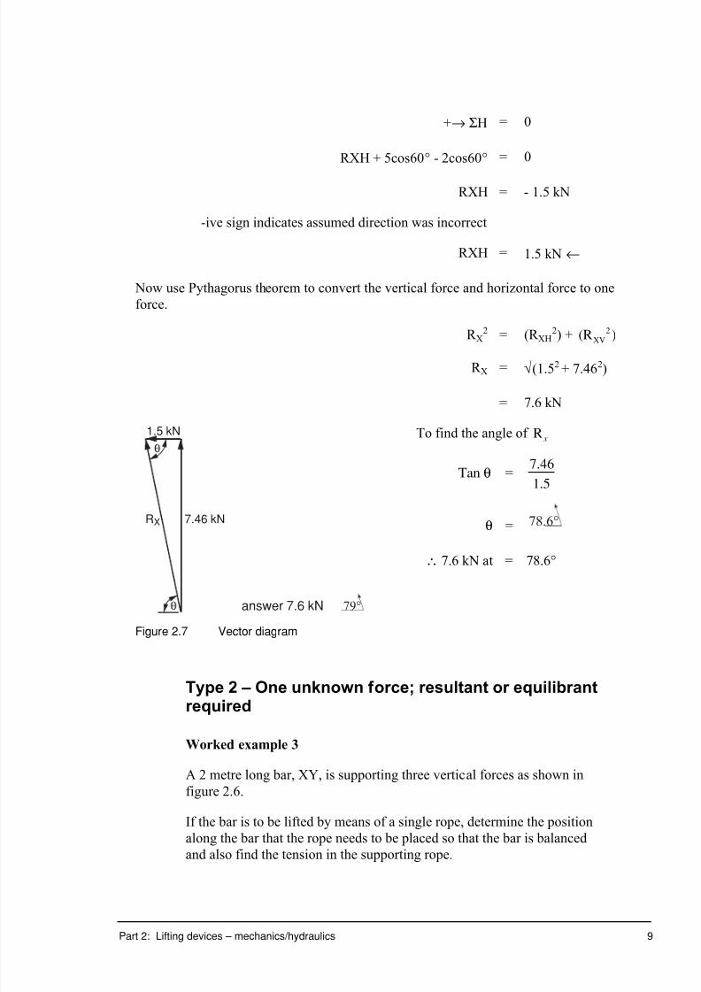
7/31/2019 3 Lifting Devices
http://slidepdf.com/reader/full/3-lifting-devices 84/281

7/31/2019 3 Lifting Devices
http://slidepdf.com/reader/full/3-lifting-devices 85/281
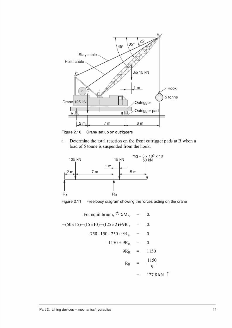
7/31/2019 3 Lifting Devices
http://slidepdf.com/reader/full/3-lifting-devices 86/281

7/31/2019 3 Lifting Devices
http://slidepdf.com/reader/full/3-lifting-devices 87/281

7/31/2019 3 Lifting Devices
http://slidepdf.com/reader/full/3-lifting-devices 88/281
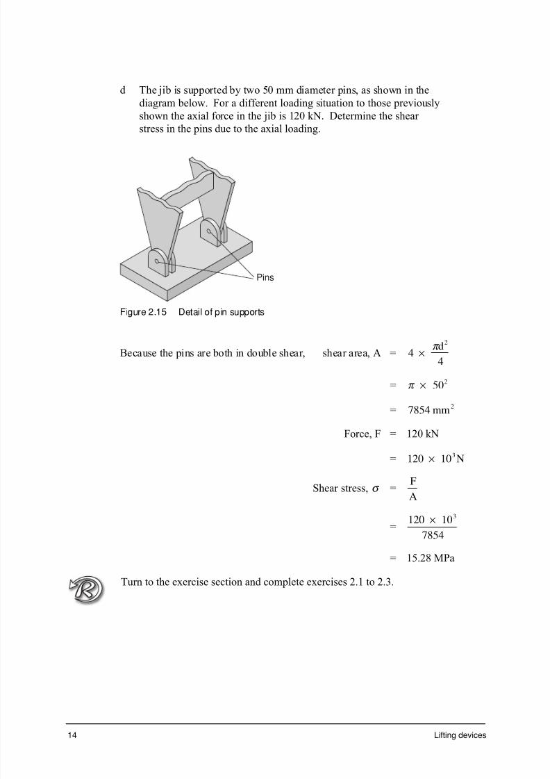
7/31/2019 3 Lifting Devices
http://slidepdf.com/reader/full/3-lifting-devices 89/281

7/31/2019 3 Lifting Devices
http://slidepdf.com/reader/full/3-lifting-devices 90/281

7/31/2019 3 Lifting Devices
http://slidepdf.com/reader/full/3-lifting-devices 91/281
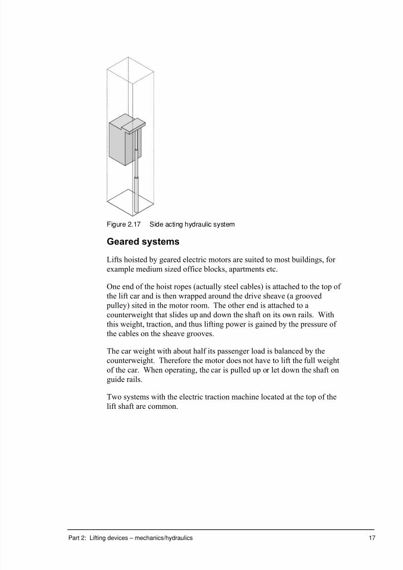
7/31/2019 3 Lifting Devices
http://slidepdf.com/reader/full/3-lifting-devices 92/281

7/31/2019 3 Lifting Devices
http://slidepdf.com/reader/full/3-lifting-devices 93/281

7/31/2019 3 Lifting Devices
http://slidepdf.com/reader/full/3-lifting-devices 94/281
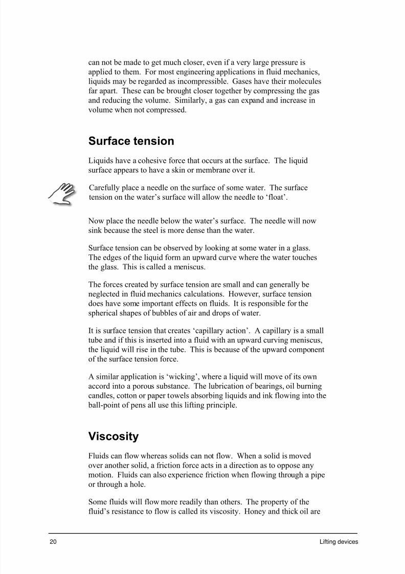
7/31/2019 3 Lifting Devices
http://slidepdf.com/reader/full/3-lifting-devices 95/281

7/31/2019 3 Lifting Devices
http://slidepdf.com/reader/full/3-lifting-devices 96/281

7/31/2019 3 Lifting Devices
http://slidepdf.com/reader/full/3-lifting-devices 97/281
22 Lifting devices
Since water is a very commonly used liquid, you should memorise these
facts:
• 1 cubic metre of water has a mass of 1 tonne
• 1 litre of water has a mass of 1 kilogram.
Relative density (RD)
Relative density is the ratio of the density of a substance to the density of
water.
RD (substance) =r
rsubstance
water
( )
( )
Because relative density is a ratio, it has no units.
Worked example 5
The relative density of mercury is 13.6. Calculate its density.
RD (mercury) =r
rsubstance
water
( )
( )
13.6 =r
1000
r = 13 6 103 3. ¥ k g / m
Specific volume ( nn n n)
The word ‘specific’ usually means per unit mass.
The specific volume then is volume per unit mass.
v =V
m
13.6 =1
R
(the inverse of density)
Units for specific volume are m kg3 .
Specific volume is mainly used for gases.
Specific gravity
The specific gravity of a substance is the ratio of the density of the
substance to the density of water R water kg m/ .= ¥( )1 103 3

7/31/2019 3 Lifting Devices
http://slidepdf.com/reader/full/3-lifting-devices 98/281
Part 2: Lifting devices – mechanics/hydraulics 23
Pressure (p)
The pressure on an object is the force (F) acting perpendicular to a given
surface area (A).
R =F
A
The unit for pressure is the newton per square metre (N/m2) or pascal
(Pa). The pascal was named in honour of Pascal who formulated much of
fluid mechanics.
1 pascal (Pa) = 1 N/m2
One pascal is a relatively small amount of pressure, roughly equivalent to
the pressure exerted by a five dollar note on a level surface.
It is more usual to express pressure in either kilopascal (kPa) or
megapascal (MPa).
1 MPa = 1 N/mm2
1 MPa is about the weight of an orange (1N) resting on the end of a
vertical matchstick (1mm x 1mm).
Pressure is a scalar quantity, acting with equal magnitude in all
directions.
Gases exert pressure on all sides of the container in which the are
enclosed. A liquid exerts pressure on a container where it touches the
sides and the bottom. Inside a gas or a liquid pressure is exerted in all
direction due to the movement of the molecules.
Solids exert pressure due to their weight pushing down on the surface on
which they sit. But inside the solid, the molecules have no translational
movement, so they cannot exert pressure in other directions.
Atmospheric pressure (patm)
Atmospheric pressure is the pressure associated with the atmosphere due
to the weight of air.
This pressure will vary according to the location and weather conditions.
The average value or ‘normal’ or ‘standard’ atmospheric pressure at sea
level is 101.3 kPa, that is, at the earth's surface the pressure felt by an
object due to the weight of the atmosphere above it is 1 013 105. ¥ Pa or
101.3 kPa. This is also called a pressure of 1 atmosphere.
At higher elevations atmospheric pressure is less.
7/31/2019 3 Lifting Devices
http://slidepdf.com/reader/full/3-lifting-devices 99/281
7/31/2019 3 Lifting Devices
http://slidepdf.com/reader/full/3-lifting-devices 100/281

7/31/2019 3 Lifting Devices
http://slidepdf.com/reader/full/3-lifting-devices 101/281

7/31/2019 3 Lifting Devices
http://slidepdf.com/reader/full/3-lifting-devices 102/281

7/31/2019 3 Lifting Devices
http://slidepdf.com/reader/full/3-lifting-devices 103/281

7/31/2019 3 Lifting Devices
http://slidepdf.com/reader/full/3-lifting-devices 104/281
7/31/2019 3 Lifting Devices
http://slidepdf.com/reader/full/3-lifting-devices 105/281
30 Lifting devices
Pressure, p =F
A
=900
491
= 1.83 Mpa
c Determine the load the jack can lift on the 90 mm diameter
piston when the effort is 90 N.
Area of plunger, A =p d
4
2
=p 90
4
2( )
= 6362 2mm
Pressure, p =
F
A
Load, F = p ¥ A
= 1.83 x 6362
= 11642.5 N
= 11.6 kN
d Determine the mechanical advantage of the hydraulic jack.
Mechanical advantage, MA =Load
Effort
=11642 5
90
.
= 129
Note: this MA is achieved through the MA of the lever and the MA of
the hydraulic system.
Turn to the exercise section and complete exercise 2.4.
7/31/2019 3 Lifting Devices
http://slidepdf.com/reader/full/3-lifting-devices 106/281
Part 2: Lifting devices – mechanics/hydraulics 31
Stress and pressure
Stress and pressure are both defined as force per unit area and have the
same units. However, they are two entirely different things and must be
understood separately. Stress is only used with solids, whereas pressuremust only be used with fluids and gases.
Many solid pieces of machines and structures interface with fluids under
pressure.
The difference between stress and pressure is explained by Pascal’s
principle.
Principle 3 (Pascal’s principle)
A pressure applied to an enclosed fluid at rest is transmitted without loss
in all directions throughout the system.
Pascal’s principle applies to fluids, but not to solids. A fluid has the
ability to transfer pressure to all parts of a container equally in all
directions.
It applies for static conditions and neglects the weight of the fluid. If the
fluid is moving, or if the weight of the fluid is not negligible, then
Pascal’s principle must be modified using other principles involving
hydraulics, pneumatics or fluid mechanics.
An important consequence of Pascal’s principle is that a force can be
magnified or reduced by means of fluid pressure. This is the main reason
why pneumatic and hydraulic systems are so widely used.
A relatively small force applied to a piston with a small diameter can
generate a large pressure. As the ram is of much larger diameter, the
same fluid pressure acting over a larger area will magnify the force at the
piston to a much larger force at the ram.
Consider a system of enclosed fluids as shown.

7/31/2019 3 Lifting Devices
http://slidepdf.com/reader/full/3-lifting-devices 107/281
32 Lifting devices
Pressure p
Piston force
Piston
Pressure p
Pressure gauge
Fluid
Gas
Ram forceRam
A
BC
Figure 2.27 Pressure transmission in a fluid
If the piston is held in position, each of the pressure gauges will register a
pressure. These pressures are not necessarily the same.
Pascal’s principle applies to both liquids and gases. In hydraulics, gas in
the system is a nuisance because much of the applied pressure results in
the compression of the gas rather than movement of the ram. To work
properly, the system must be bled to remove any gas before use.
Worked example 8
Consider the system of enclosed fluids in figure 2.27. The piston has adiameter of 12 mm and the ram has a diameter of 75 mm. The pressure
gauge at A registers 70 kPa, and B and C indicate 65 kPa and 60 kPa,
respectively.
A force is applied to the piston after which gauge A reads as 90 kPa.
a Determine the reading on the other two pressure gauges B and C.
Applied pressure will be 90 – 70 = 20 kPa.
By Pascal’s principle, each gauge will register 20 kPa higher.
Gauge B will now read 65 + 20 = 85 kPa and gauge C will read 80kPa.
b Identify the ratio of the force at the ram to the force at the piston.
Remember that the pressure remains constant throughout the system.
Pressure, p, will equal.
Pressure =F
A
\Fpiston = p Apiston ¥
and Fram = p A ram¥
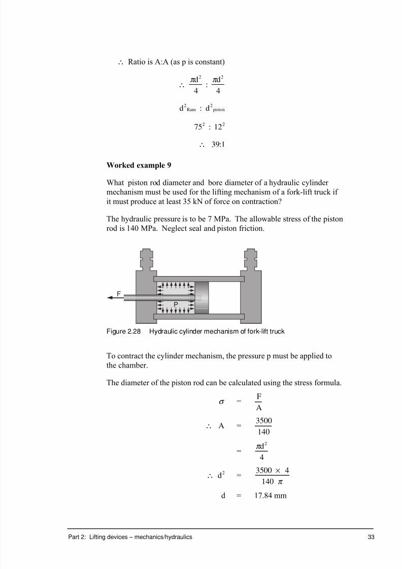
7/31/2019 3 Lifting Devices
http://slidepdf.com/reader/full/3-lifting-devices 108/281
Part 2: Lifting devices – mechanics/hydraulics 33
\ Ratio is A:A (as p is constant)
\ :p p d d2 2
4 4
d dRam piston2 2:
75 122 2:
\ :39 1
Worked example 9
What piston rod diameter and bore diameter of a hydraulic cylinder
mechanism must be used for the lifting mechanism of a fork-lift truck if
it must produce at least 35 kN of force on contraction?
The hydraulic pressure is to be 7 MPa. The allowable stress of the piston
rod is 140 MPa. Neglect seal and piston friction.
P
F
Figure 2.28 Hydraulic cylinder mechanism of fork-lift truck
To contract the cylinder mechanism, the pressure p must be applied to
the chamber.
The diameter of the piston rod can be calculated using the stress formula.
s = FA
\ A =3500
140
=p d2
4
\ d2 =3500 4
140
¥p
d = 17.84 mm
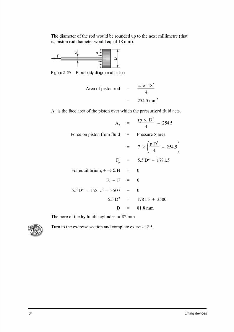
7/31/2019 3 Lifting Devices
http://slidepdf.com/reader/full/3-lifting-devices 109/281
7/31/2019 3 Lifting Devices
http://slidepdf.com/reader/full/3-lifting-devices 110/281

7/31/2019 3 Lifting Devices
http://slidepdf.com/reader/full/3-lifting-devices 111/281
7/31/2019 3 Lifting Devices
http://slidepdf.com/reader/full/3-lifting-devices 112/281
Part 2: Lifting devices – mechanics/hydraulics 37
1 Perform an activity to measure the weight of an object in air and the
weight of the same object in a liquid. Measure the weight of the
fluid displaced by the submerged object, and analyze the
measurements obtained.
2 Determine the weight of a small metal object. Place the object into
an overflow can. Collect the water displaced from the can and
calculate the volume and weight of the displaced water.
Record the weight of the object when submerged in water, by
attaching it to a spring balance. Determine the weight of the liquid
displaced and compare it to the apparent weight of the submerged
object due to the buoyant force. The weight loss of the submerged
object should be equal to the weight of water displaced.
3 Repeat for an object which floats. Carefully examine how the
apparent loss in weight of a floating object compares to the weight of the liquid it displaces.
Report on your findings.
__________________________________________________________
__________________________________________________________
__________________________________________________________
__________________________________________________________
__________________________________________________________
__________________________________________________________
__________________________________________________________
__________________________________________________________
__________________________________________________________
__________________________________________________________
__________________________________________________________ __________________________________________________________
__________________________________________________________
__________________________________________________________
__________________________________________________________

7/31/2019 3 Lifting Devices
http://slidepdf.com/reader/full/3-lifting-devices 113/281
38 Lifting devices
4 Place uninflated balloons 30 cm apart around the perimeter of a
rectangular table. Invert a second table face down on the one below,
so that the open ends of the balloons are all protruding out from
between the tables. Invite someone to sit in the middle of the
inverted table. Get as many volunteers as there are balloons. Ask each volunteer to blow into a balloon, to see if they can lift the
inverted table with the person sitting on it.
Turn to the exercise section and complete exercise 2.6 and 2.7.

7/31/2019 3 Lifting Devices
http://slidepdf.com/reader/full/3-lifting-devices 114/281

7/31/2019 3 Lifting Devices
http://slidepdf.com/reader/full/3-lifting-devices 115/281

7/31/2019 3 Lifting Devices
http://slidepdf.com/reader/full/3-lifting-devices 116/281

7/31/2019 3 Lifting Devices
http://slidepdf.com/reader/full/3-lifting-devices 117/281
42 Lifting devices
Exercise 2.3
A mobile crane with the necessary dimensions for a force analysis is
shown in the diagram. The point C represents the centre of mass of the
mobile crane, mass 2.5 tonnes.
Mass6 tonnes
45∞
1500 3000 4000
C
3 5 0 0
7 5 0 0
Hydrauliccylinder
90∞
A B
Figure 2.34 Mobile crane
a For the loading arrangement shown, determine the force on the
hydraulic cylinder.

7/31/2019 3 Lifting Devices
http://slidepdf.com/reader/full/3-lifting-devices 118/281

7/31/2019 3 Lifting Devices
http://slidepdf.com/reader/full/3-lifting-devices 119/281

7/31/2019 3 Lifting Devices
http://slidepdf.com/reader/full/3-lifting-devices 120/281

7/31/2019 3 Lifting Devices
http://slidepdf.com/reader/full/3-lifting-devices 121/281
46 Lifting devices
Exercise 2.4
A hydraulic jack is shown in the sketch below.
50450LoadEffort
PistonØ 90
PlungerØ 25
Fluid
Figure 2.35 Hydraulic jack
A load of 1.3 tonnes is to be lifted with the jack.
Determine the effort that must be exerted at the end of the handle to lift
the load.

7/31/2019 3 Lifting Devices
http://slidepdf.com/reader/full/3-lifting-devices 122/281
7/31/2019 3 Lifting Devices
http://slidepdf.com/reader/full/3-lifting-devices 123/281
7/31/2019 3 Lifting Devices
http://slidepdf.com/reader/full/3-lifting-devices 124/281

7/31/2019 3 Lifting Devices
http://slidepdf.com/reader/full/3-lifting-devices 125/281

7/31/2019 3 Lifting Devices
http://slidepdf.com/reader/full/3-lifting-devices 126/281
Part 2: Lifting devices – mechanics/hydraulics 51
10 Atmospheric pressure is
a always equal to 101.3 kPa
b always equal to 760 mm of mercury
c called a vacuum when it is low
d associated with the atmosphere due to the weight of air.

7/31/2019 3 Lifting Devices
http://slidepdf.com/reader/full/3-lifting-devices 127/281
52 Lifting devices

7/31/2019 3 Lifting Devices
http://slidepdf.com/reader/full/3-lifting-devices 128/281

7/31/2019 3 Lifting Devices
http://slidepdf.com/reader/full/3-lifting-devices 129/281

7/31/2019 3 Lifting Devices
http://slidepdf.com/reader/full/3-lifting-devices 130/281
Part 2: Lifting devices – mechanics/hydraulics 55
Exercise cover sheet
Exercises 2.1 to 2.7 Name: _______________________________
Check!Have you have completed the following exercises?
❐ Exercise 2.1
❐ Exercise 2.2
❐ Exercise 2.3
❐ Exercise 2.4
❐ Exercise 2.5
❐ Exercise 2.6
❐ Exercise 2.7
Locate and complete any outstanding exercises then attach your
responses to this sheet.
If you study Stage 6 Engineering Studies through a Distance Education
Centre School (DEC) you will need to return the exercise sheet and your
responses as you complete each part of the module.
If you study Stage 6 Engineering Studies through the OTEN Open
Learning Program (OLP) refer to the Learner’s Guide to determine whichexercises you need to return to your teacher along with the Mark Record
Slip.

7/31/2019 3 Lifting Devices
http://slidepdf.com/reader/full/3-lifting-devices 131/281
Lifting devices
Part 3: Lifting devices –materials
7/31/2019 3 Lifting Devices
http://slidepdf.com/reader/full/3-lifting-devices 132/281
Part 3: Lifting devices – materials 1
Part 3 contents
Introduction..........................................................................................2
What will you learn?...................................................................2
Jacks, elevators, cranes....................................................................3
Testing of materials ................................................................... 6
Heat treatment .........................................................................13
Forming processes..................................................................19
Exercises ...........................................................................................33
Progress check .................................................................................43
Exercise cover sheet........................................................................45

7/31/2019 3 Lifting Devices
http://slidepdf.com/reader/full/3-lifting-devices 133/281

7/31/2019 3 Lifting Devices
http://slidepdf.com/reader/full/3-lifting-devices 134/281
Part 3: Lifting devices – materials 3
Jacks, elevators, cranes
The following diagrams of lifting devices are included to assist in the
identification of the various component parts.
Floor jacks
Most of the materials used in floor jacks are iron-based alloys. Hydraulic
cylinders are cast iron, pistons are chrome plated low carbon steel, bodies
may be cast steel or fabricated in low carbon steel, lifting arms, pivot
pins and tension screws are low carbon steel, wheels are cast iron and
bleed screws are low carbon steel.
Screw jack
Load cap
Lever bar
Ductile-iron housing
Welded stop
Single chrome-molybdenumball reduces operating friction
Four-way headpermits lever barinsertion at four angles
Figure 3.1 Screw jack
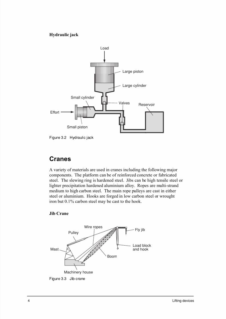
7/31/2019 3 Lifting Devices
http://slidepdf.com/reader/full/3-lifting-devices 135/281

7/31/2019 3 Lifting Devices
http://slidepdf.com/reader/full/3-lifting-devices 136/281

7/31/2019 3 Lifting Devices
http://slidepdf.com/reader/full/3-lifting-devices 137/281

7/31/2019 3 Lifting Devices
http://slidepdf.com/reader/full/3-lifting-devices 138/281
Part 3: Lifting devices – materials 7
From the information available in previous modules, summarise the steps
in performing a tensile test on a standardised specimen.
___________________________________________________________
___________________________________________________________
___________________________________________________________
___________________________________________________________
___________________________________________________________
___________________________________________________________
___________________________________________________________
___________________________________________________________
___________________________________________________________
___________________________________________________________
The graph in figure 3.6 shows the result of a tensile test on a low carbon
steel.
L o a d
( k N )
Extension (mm)
Maximum load
Elastic limit
Failure point
Figure 3.6 Load/extension graph for low carbon steel
The shape of a load/extension graph tells a good deal about the
mechanical properties of the material. These properties include:
• toughness this is determined from the total area under the curve
• resilience this is the area under the straight-line section of the
graph

7/31/2019 3 Lifting Devices
http://slidepdf.com/reader/full/3-lifting-devices 139/281
8 Lifting devices
• elasticity the angle of the straight-line section of the graph
indicates elasticity – the steeper the line, the stiffer the
material
• brittleness a material that doesn't show much plastic deformation
is rigid and brittle – the graphs for some ceramic
materials are only a straight line with no curve at all
• ductility any graph that shows a large area of plastic
deformation and possibly a failure point that is below
the ultimate tensile strength (UTS) is said to be
ductile
• strength the amount of force needed to plastically deform the
material is the proof or yield strength while the 'high
point' of the graph is the UTS.
Before the load/extension graphs for a variety of materials can beaccurately compared, the cross-sectional areas and the original length of
each specimen must be taken into account.
Naturally a telegraph pole will withstand a greater load than a steel guitar
string but that doesn't necessarily mean that timber is stronger than steel.
In fact from our previous learning we know that steel is stronger than
timber.
To allow comparison of tensile test results, the load must be divided by
the cross-sectional area to give the stress (s) and the extension must be
divided by the original length to give the strain (e). Once this is done,
graphs can be directly compared or even drawn on the same set of axes.
Note: different units for strain
S t r e s s ( M P a )
Strain
250
200
150
100
150
0 1 2 3 4 5
Grey cast iron
300
S t r e s s ( M P a )
Strain
250
200
150
100
150
0 10 20 30 40 50
Normalised mediumcarbon steel
Normalised lowcarbon steel
300
Figure 3.7 Tensile test results for common irons and steels

7/31/2019 3 Lifting Devices
http://slidepdf.com/reader/full/3-lifting-devices 140/281
Part 3: Lifting devices – materials 9
Compare the stress/strain curves in figure 3.7 and suggest which material
has the highest:
Toughness __________________________________________________
Resilience __________________________________________________
Strength____________________________________________________
Ductility ___________________________________________________
Stiffness____________________________________________________
Did you answer?
Medium carbon steel appears to be the strongest and most resilient while lowcarbon steel is the most ductile and grey cast iron is the stiffest. One of thesteels is the toughest, though it might be necessary to calculate the areas under the curves, since it is difficult to assess visually.
Compression test
Many parts involved in lifting devices are subjected to compressive
loads. Hydraulic rams in some cranes, elevators and many modern jacks
are all subject to compressive loads. In all lifting devices some part must be under compression to allow lifting to occur. As a tower crane lifts a
load at a building site, the cables will be in tension but the tower itself
will be under an additional compressive force equal in magnitude to the
tensile force in the cables.
In previous modules, both Preliminary and HSC, some detail has been
given of compression testing.
As with tensile testing, standardised specimens can be used to produce
load/reduction graphs that can then be converted to stress/strain graphs.
The specimen is positioned between two hard and rigid platens and acompressive load is gradually applied. With brittle materials, such as
concrete and stone, there is a definite failure point. In ductile materials,
like those used in lifting devices, there is no definite failure point and
specimens often bulge in the middle. This effect is known as barrelling.
To provide an accurate test result, the ends of the specimen must be
parallel and the specimen must have a large enough cross-sectional area
to prevent it from bending or tipping rather than compressing. This
means the specimen is normally larger than the one used for tensile tests
and consequently the testing machine must be larger and capable of
applying a greater load.

7/31/2019 3 Lifting Devices
http://slidepdf.com/reader/full/3-lifting-devices 141/281
10 Lifting devices
Figure 3.8 Barrelling in ductile materials
Hardness tests
The Brinell, Vickers and Rockwell hardness tests were described in
detail in the preliminary module on Braking Systems.
Complete the table below to provide a summary of three common types
of hardness test, refer back at the previous modules or textbooks if you
need to.
Hardnesstest
Indentor Measured Used On
Brinell
the diameter ofthe circularindentation ismeasured using alow-poweredmicroscope
Vickers
industrial
diamond cut toa square-basedpyramid.
Rockwell
used on a fullrange ofmaterials with awide range ofhardness

7/31/2019 3 Lifting Devices
http://slidepdf.com/reader/full/3-lifting-devices 142/281
Part 3: Lifting devices – materials 11
Safety systems on elevators, surfaces on gears and pulleys in cranes and
faces of hydraulic cylinders all need to be hard in order to resist wear.
The materials used for these components, the forming processes
employed and any heat treatments applied all contribute to the hardness
of the components.
The data collected from hardness testing can be used to initially select the
correct material or heat treatment for an application and also to assess the
effect of the forming process. These tests are also used on the production
line to provide checks on the quality of the raw materials and production
processes.
Notched-bar impact tests
Jacks, cranes and elevators are usually subjected to a variety of loads
including gradually applied and impact loads. To assess the safe
performance of these lifting devices under impact loads each device must
be thoroughly tested. As the behaviour of materials under impact loads
can be vastly different to their behaviour under gradually applied loads, it
is also important that each of the component materials is tested under
impact or dynamic loads.
Standardised impact tests use a standard specimen with a standard notch
cut into it. The results of dynamic testing of this type are interesting.
The dynamically tested impact strength of an unnotched specimen issimilar to the toughness that is assessed from the area under the curve of
a stress/strain diagram.
The use of notched specimens provides a stress point and even ductile
materials display a brittle type of fracture. The notched-toughness of
dynamically tested materials is much less than the toughness figures
expected from stress/strain diagrams.
Suggest some materials that would have very low notched-toughness.
___________________________________________________________
___________________________________________________________
Did you answer?
Did you suggest brittle materials like white cast iron, grey cast iron andhardened high carbon steel.
Notched-bar impact tests were described in detail in the Preliminary
module on Braking Systems and in the previous HSC module.

7/31/2019 3 Lifting Devices
http://slidepdf.com/reader/full/3-lifting-devices 143/281

7/31/2019 3 Lifting Devices
http://slidepdf.com/reader/full/3-lifting-devices 144/281
Part 3: Lifting devices – materials 13
Crane hooks and safety chains are commonly subjected to proving tests
before being used and new design concepts in jacks are also subjected to
proving tests under actual loading conditions.
Each of these lifting devices is subject to maximum loads. The number of persons allowed in an elevator is normally clearly indicated on the
control panel. The lifting capacity of jacks and cranes is labelled clearly,
often with a warning about overloading. Obviously manufacturers
understand that people will always stretch lifting devices to their loading
limits so it is important that proving tests overload the devices and
therefore include a factor of safety in the loading limits.
Turn to the exercise section and complete exercise 3.2.
Heat treatment
Various heat treatment processes have been discussed in detail in
previous Preliminary and HSC modules.
Give definitions of the following processes, use information from
previous modules if you need to.
Normalising
__________________________________________________________
Hardening
___________________________________________________________
Tempering
___________________________________________________________
Did you answer?
In summary, normalising involves heating and cooling in still air, hardeninginvolves heating and quenching and tempering is the reheating of a hardenedstructure to reduce some of the brittleness while retaining hardness.
In this part, you will take a closer look at the internal structure that
results from these heat treatment processes and the typical properties that
result.
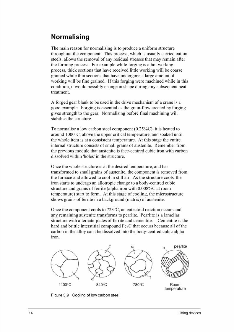
7/31/2019 3 Lifting Devices
http://slidepdf.com/reader/full/3-lifting-devices 145/281

7/31/2019 3 Lifting Devices
http://slidepdf.com/reader/full/3-lifting-devices 146/281
Part 3: Lifting devices – materials 15
The final microstructure shows uniformly fine-grained ferrite and pearlite
throughout. As the cooling rate in normalising is faster than equilibrium
cooling, there is less time for the grains of ferrite to form before the
eutectoid reaction takes place. This means there will be more pearlite in
a normalised structure than in an annealed structure of the samecomposition.
Properties resulting from normalising
As previously mentioned, normalising is used to refine grain structure so
it is the same throughout the component (homogenous). It is used to
remove the stresses induced during forming processes and to eliminate
columnar grains and dendritic segregation that sometimes occurs during
casting. Normalising improves the machinability of the component and provides dimensional stability if the component is subjected to further
heat treatment.
Normalising produces harder and stronger steel than annealing due to a
number of factors including:
• the greater amount of pearlite found in the normalised structure
because of the non-equilibrium cooling.
• the pearlite is fine not coarse, as in annealed structures, which means
that there is not as much soft and ductile ferrite separating the plates
of hard and brittle cementite. This tends to stiffen the structureincreasing both the hardness and strength.
Normalising in lifting devices
A number of components found in lifting devices would be normalised.
These include:
• forged and cast steel crane hooks
• cast steel jack bodies
• fabricated steel lifting chains
• forged steel gear blanks
• cast iron pulleys in cranes
• cast brackets used in elevator assemblies.
Turn to the exercise section and complete exercise 3.3.

7/31/2019 3 Lifting Devices
http://slidepdf.com/reader/full/3-lifting-devices 147/281
7/31/2019 3 Lifting Devices
http://slidepdf.com/reader/full/3-lifting-devices 148/281
Part 3: Lifting devices – materials 17
Did you answer?
Tempering allows some of the carbon in the martensite to diffuse which relievessome of the stresses and reduces brittleness and hardness.
Identify components of jacks, elevators and cranes to suggest some
components of each that you feel would be hardened and tempered.
___________________________________________________________
___________________________________________________________
Did you answer?
Did you suggest parts like the teeth of gears in cranes and mechanical jacks andwear plates in the safety devices in elevators.
Properties resulting from hardening andtempering
The hardness of martensite depends on the carbon content of the steel.
The greater amount of carbon produces maximum strain of the lattice
structure and therefore the greatest hardness and brittleness.
Different quenching media cool the steel at different rates and can be
useful in hardening a variety of steels. Steels with higher carboncontents must be quenched slowly to avoid cracking while lower carbon
steels need very rapid quenching to produce maximum stress in the
lattice structure. Common quenching media from rapid to slow cooling
are:
• hydroxide solution
• salt water (10%) or brine
• agitated.
Hardenability
This term refers to the depth to which steel hardens. When the steel is
quenched the surface cools rapidly but the inside cools at a slower rate.
The depth of martensite, in plain carbon steel, might only be two to three
millimetres with pearlite forming below this depth. Alloy steels have
been developed that, once quenched, show martensite to a depth of
50 mm or more. Other alloys, containing 5% nickel and 1.5 %
chromium, change to martensite even after cooling in still air and are
known as air-hardening steels. Alloy steels are always used when adepth of hardness is required.
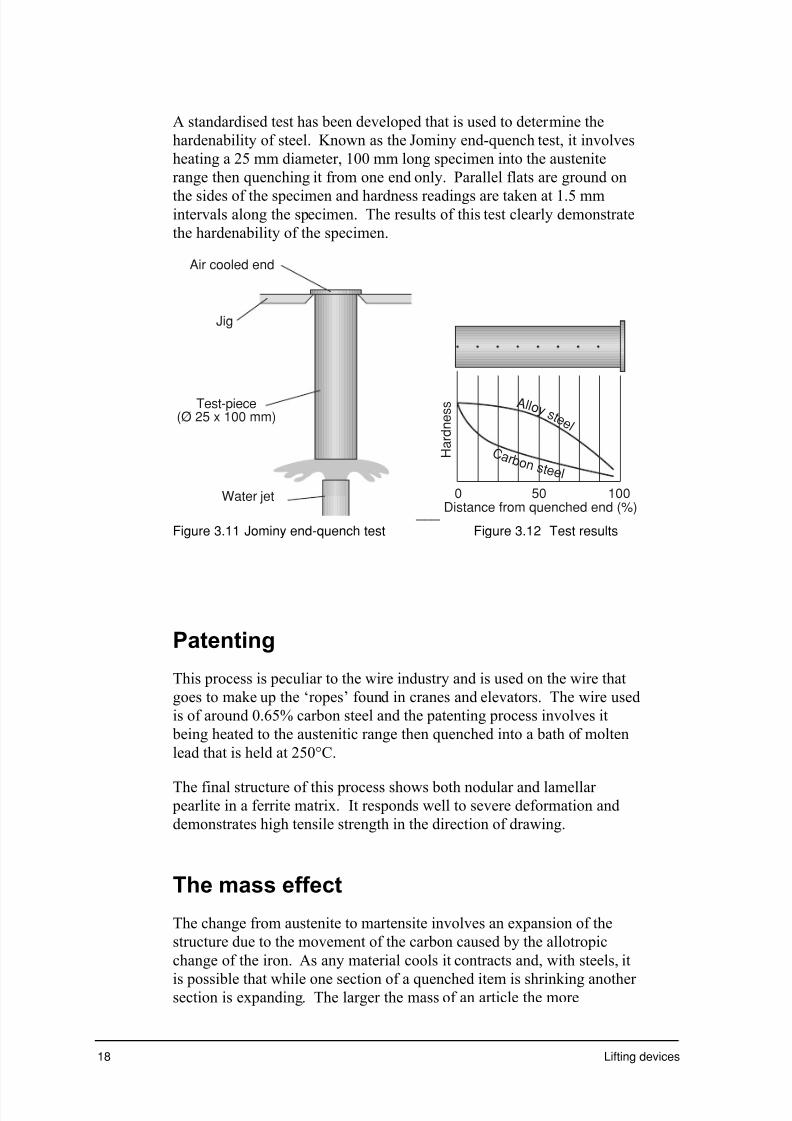
7/31/2019 3 Lifting Devices
http://slidepdf.com/reader/full/3-lifting-devices 149/281
18 Lifting devices
A standardised test has been developed that is used to determine the
hardenability of steel. Known as the Jominy end-quench test, it involves
heating a 25 mm diameter, 100 mm long specimen into the austenite
range then quenching it from one end only. Parallel flats are ground on
the sides of the specimen and hardness readings are taken at 1.5 mmintervals along the specimen. The results of this test clearly demonstrate
the hardenability of the specimen.
Test-piece(Ø 25 x 100 mm)
Water jet
Air cooled end
Jig
___ Distance from quenched end (%)0 50 100
H a r d n e s s Al l o y
s t e e l
C a r b o n s t e e l
Figure 3.11 Jominy end-quench test Figure 3.12 Test results
Patenting
This process is peculiar to the wire industry and is used on the wire that
goes to make up the ‘ropes’ found in cranes and elevators. The wire used
is of around 0.65% carbon steel and the patenting process involves it
being heated to the austenitic range then quenched into a bath of molten
lead that is held at 250°C.
The final structure of this process shows both nodular and lamellar pearlite in a ferrite matrix. It responds well to severe deformation and
demonstrates high tensile strength in the direction of drawing.
The mass effect
The change from austenite to martensite involves an expansion of the
structure due to the movement of the carbon caused by the allotropic
change of the iron. As any material cools it contracts and, with steels, it
is possible that while one section of a quenched item is shrinking another section is expanding. The larger the mass of an article the more

7/31/2019 3 Lifting Devices
http://slidepdf.com/reader/full/3-lifting-devices 150/281
Part 3: Lifting devices – materials 19
pronounced the differences in cooling rates and the more likely the item
is to crack due to quenching.
Two processes, Martempering and Austempering, have been developed
that allow large masses to be cooled without developing quench cracks.
In both these processes, the component to be heat-treated is heated till the
structure is all austenite. The component is then quenched in a lead or
salt bath that is held at a temperature just above the temperature at which
the cooling steel will change into martensite.
In Martempering, the component is held in the bath till it is a uniform
temperature throughout. It is then water-quenched producing a full
martensite structure. The shrinking, due to cooling, and the expansion
due to the austenite-martensite transformation are separated by this
process and cracking is eliminated.
Sketch and label, in figure 3.13, the microstructure of the martensite that
results from martempering.
Figure 3.13 Martensite
In Austempering, the component is held in the ‘bath’ till the austenite has
changed to a ferrite matrix with carbide particles finely dispersed
throughout. This new structure is softer than martensite with similar
carbon content but has greater shock resistance.
Turn to the exercise section and complete exercise 3.4.
Forming processes
Jacks, cranes and elevators all use component parts that have been
manufactured using a variety of forming processes. Each of these
processes alters the structure of the material being formed. These
changes in structure produce properties that are often desirable in these
component parts.

7/31/2019 3 Lifting Devices
http://slidepdf.com/reader/full/3-lifting-devices 151/281
20 Lifting devices
Forging
Both hot and cold forging are used on various parts of lifting devices and
the major reason for using forging is that the component’s strength
properties are all increased in the direction of the forging.
In hot drop forging, a set of special dies are made from hardened and
tempered carbon steel or special alloy steel. The upper-half of the die is
attached to the hammer and the lower half is attached to the anvil. These
dies provide a series of stages to allow the metal to ‘flow’ into the shape
of the final die. The stages in forging are:
• metal blank cut from stock then heated and placed in the lower die
• rough forming is carried out in the first set of dies
• final forming takes place in the finishing dies• trim dies are used to remove flash from the forging.
For ease of forgeability, mild steel is by far the best materials, followed
by aluminium, copper, nickel and stainless steel.
Temperature range for common metals and alloys
Metal Temperature Range °C
Steel low – medium carbon 800 – 1300
Steel high carbon 750 – 1100
Steel alloys (including stainless) 950 – 1200
Copper 450 – 1000
Copper alloys 600 – 800
Aluminium and alloys 325 – 475
Aluminium bronze 800 – 900
Grainflow
When cast stock is hot forged the material is plastically deformed and
then immediately starts to recrystalise. Any cored grains remaining from
the casting process disappear and segregations and slag inclusions are
spread throughout the structure.
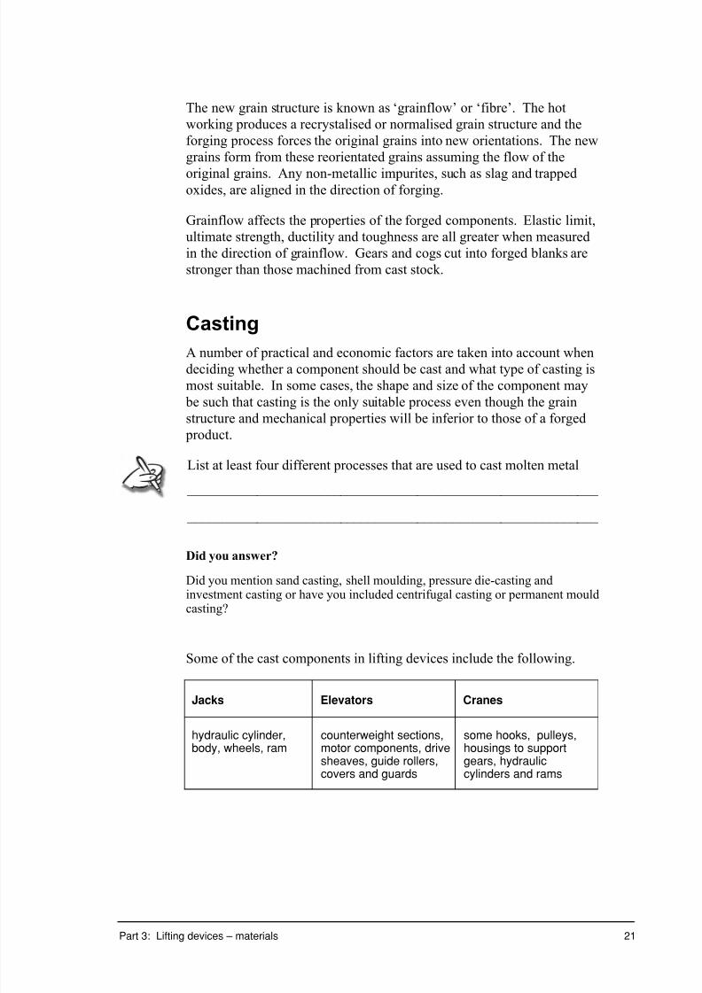
7/31/2019 3 Lifting Devices
http://slidepdf.com/reader/full/3-lifting-devices 152/281
Part 3: Lifting devices – materials 21
The new grain structure is known as ‘grainflow’ or ‘fibre’. The hot
working produces a recrystalised or normalised grain structure and the
forging process forces the original grains into new orientations. The new
grains form from these reorientated grains assuming the flow of the
original grains. Any non-metallic impurites, such as slag and trappedoxides, are aligned in the direction of forging.
Grainflow affects the properties of the forged components. Elastic limit,
ultimate strength, ductility and toughness are all greater when measured
in the direction of grainflow. Gears and cogs cut into forged blanks are
stronger than those machined from cast stock.
Casting
A number of practical and economic factors are taken into account whendeciding whether a component should be cast and what type of casting is
most suitable. In some cases, the shape and size of the component may
be such that casting is the only suitable process even though the grain
structure and mechanical properties will be inferior to those of a forged
product.
List at least four different processes that are used to cast molten metal
___________________________________________________________
___________________________________________________________
Did you answer?
Did you mention sand casting, shell moulding, pressure die-casting andinvestment casting or have you included centrifugal casting or permanent mouldcasting?
Some of the cast components in lifting devices include the following.
Jacks Elevators Cranes
hydraulic cylinder,body, wheels, ram
counterweight sections,motor components, drivesheaves, guide rollers,covers and guards
some hooks, pulleys,housings to supportgears, hydrauliccylinders and rams

7/31/2019 3 Lifting Devices
http://slidepdf.com/reader/full/3-lifting-devices 153/281
7/31/2019 3 Lifting Devices
http://slidepdf.com/reader/full/3-lifting-devices 154/281
7/31/2019 3 Lifting Devices
http://slidepdf.com/reader/full/3-lifting-devices 155/281
24 Lifting devices
Thin vents on the parting line of the mould allow the air to be forced
from the mould, as the metal is injected, without letting the molten metal
squeeze out. Die-cast components typically have a surface that is harder
than the interior due to the faster cooling rate on the surface.
Solidification of cast metals
When metal is cast, the rate of cooling affects the structure of the cast
component that in turn influences the properties.
Outline the stages in the solidification process of metals.
___________________________________________________________
___________________________________________________________ ___________________________________________________________
___________________________________________________________
Grain size in a cast structure is determined both by the rate of nucleation
of the metal and the rate of grain growth. Fast cooling, as in a cold metal
mould, will result in a large number of nuclei being formed and resulting
in a fine grain structure. Under slower cooling, as in sand, shell or heated
mould casting, only a few nuclei form and have a chance to grow into
larger equiaxed grains.
Other factors that may increase the rate of nucleation and produce a fine
grain structure are:
• stirring the molten metal during solidification to break up the crystals
into smaller parts
• impurities in the melt that provide a ‘seed’ for the formation of
crystals.
When molten metal is poured into a mould, the metal ‘skins’ as it hits the
surface of the mould. Once the skin of the casting has formed, the rate of
conductivity of the mould material governs the cooling rate of the
interior.
As metal moulds easily conduct heat, as the molten metal cools many
nuclei form close to the surface of the component and dendrites start to
grow ‘reaching’ into the still molten centre of the component. The
resulting grains are long and thin and are known as columnar grains. If
the casting temperature is not too high the final grains to solidify, in the
centre of the component, will possibly be equiaxed. If the casting
temperature is too high, the columnar grains will meet forming a plane of
weakness at the centre of the casting.

7/31/2019 3 Lifting Devices
http://slidepdf.com/reader/full/3-lifting-devices 156/281
Part 3: Lifting devices – materials 25
As sand is a poor conductor of heat, the molten metal cools slowly in
conditions that are closer to equilibrium. The resulting structure is
typically a chilled ‘skin’ with fine equiaxed grains in the centre.
You may have noticed that castings don’t have sharp internal corners.The diagram in figure 3.14 shows how the use of fillet curves in corners
prevents the formation of a plane of weakness where the columnar grains
meet.
Chill crystals
Plane ofweakness
Equiaxed grains
Metal mould
Columnar grains
Fillet curve
Figure 3.14 Grain structure in a cold metal mould
Properties of cast metals
As discussed previously, the rate of cooling in cast metals influences the
final structure and therefore the mechanical properties.
The surface of any casting will always cool very rapidly when the molten
metal hits the surface of the mould. This invariably produces a very fine
grain structure and a harder ‘skin’ on the casting. In the case of grey cast
iron, there is insufficient time for the graphite to precipitate from the
cementite so the surface remains as hard and brittle white cast iron. Any
machining to occur must first remove this white cast iron skin. Tools
with very hard cutting tips, such as cemented carbide, must be used.
Generally, fine-grained materials show greater toughness, are more shock
resistant and are harder and stronger than coarse-grained materials.
Components produced by die-casting are generally fine-grained and have
more favourable properties than sand-cast components.
Castings are often heat treated (normalised) after forming. This is carried
out for a number of reasons:
• coring, that can occur when alloys are cooled under faster than
equilibrium conditions, is removed

7/31/2019 3 Lifting Devices
http://slidepdf.com/reader/full/3-lifting-devices 157/281

7/31/2019 3 Lifting Devices
http://slidepdf.com/reader/full/3-lifting-devices 158/281
Part 3: Lifting devices – materials 27
through the use of a lubricant. One method of lubrication involves the
use of a coating of phosphate salts or glass that melts under the extrusion
temperature and acts as a lubricant. Other metals have much lower yield
strength than steel; aluminium brass, lead, copper, bronze and
magnesium are all fairly easy to extrude.
In elevators, much of the trimming used in the car is extruded. Next time
that you are in an elevator, have a look at the extruded track in which the
doors run, both on the floor and at the top. They are steel extrusions that
have been plated to provide protection from corrosion.
Properties in extrusions
The process of extrusion causes an alignment of the grain structure.This results in grainflow similar to the structure found in forgings. In
cold extrusion, the grains are distorted in the direction of extrusion and
the extruded metal is stronger along its length than across.
In hot extrusion, as in hot forging, the final grain structure will be
equiaxed grains but these equiaxed grains will recrystalise from the
grains that have been forced to ‘flow’ by the extrusion process. This will
also provide directional properties in the direction of extrusion. As the
outer surface of the hot extruded metal cools more quickly than the
centre, the outer layer shows fine equiaxed grains while the grains in the
centre will be larger.
Dimensional accuracy, excellent surface finish and directional properties
are all appealing features of extruded products.
Outer surface
Figure 3.15 Grain structure resulting from extrusion
Rolling
This is the name given to the process that changes the cross-sectional
shape of a piece of metal by passing the metal through suitably shaped
and spaced rollers.

7/31/2019 3 Lifting Devices
http://slidepdf.com/reader/full/3-lifting-devices 159/281
28 Lifting devices
There are two general types of rolling mill:
• sheet, strip and plate mills
• bar, rail and joist mills.
Often, a series of roller sets in tandem form a line to enable the change
from billet to sheet to be a single continuous operation. Rolling increases
the length of the metal while reducing the thickness. The width does not
really change during the rolling process. Rolling is an effective method
of producing long lengths of material with a uniform cross-sectional
shape.
Hot billet
Scale breaker
Roughing rolls
Edging rolls
Finishing train
Coil roll
Live roller table
Finished strip
Figure 3.16 Continuous rolling mill
Some of the rolled components in lifting devices include the following.
Jacks Elevators Cranes
HotRolling
Mainframework/chassisof floor jacks,
Guide rails, safetyrails
Jib structuralmembers, windingdrum supportstructure
ColdRolling
Cover plates,framework of simplecar jacks
Button panels, doorskins
Body panels forcontrol booth.
7/31/2019 3 Lifting Devices
http://slidepdf.com/reader/full/3-lifting-devices 160/281
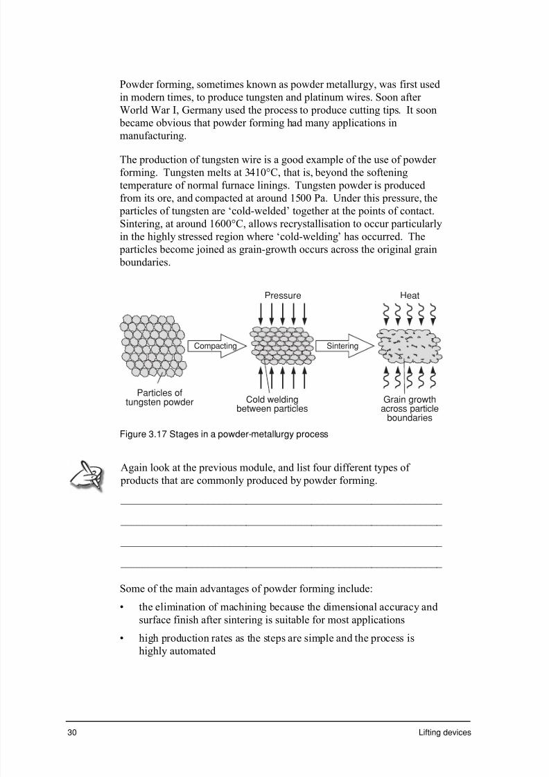
7/31/2019 3 Lifting Devices
http://slidepdf.com/reader/full/3-lifting-devices 161/281
30 Lifting devices
Powder forming, sometimes known as powder metallurgy, was first used
in modern times, to produce tungsten and platinum wires. Soon after
World War I, Germany used the process to produce cutting tips. It soon
became obvious that powder forming had many applications in
manufacturing.
The production of tungsten wire is a good example of the use of powder
forming. Tungsten melts at 3410°C, that is, beyond the softening
temperature of normal furnace linings. Tungsten powder is produced
from its ore, and compacted at around 1500 Pa. Under this pressure, the
particles of tungsten are ‘cold-welded’ together at the points of contact.
Sintering, at around 1600°C, allows recrystallisation to occur particularly
in the highly stressed region where ‘cold-welding’ has occurred. The
particles become joined as grain-growth occurs across the original grain
boundaries.
Compacting Sintering
Particles oftungsten powder Cold welding
between particles
Pressure Heat
Grain growth
across particleboundaries
Figure 3.17 Stages in a powder-metallurgy process
Again look at the previous module, and list four different types of
products that are commonly produced by powder forming.
___________________________________________________________
___________________________________________________________
___________________________________________________________
___________________________________________________________
Some of the main advantages of powder forming include:
• the elimination of machining because the dimensional accuracy and
surface finish after sintering is suitable for most applications
• high production rates as the steps are simple and the process is
highly automated
7/31/2019 3 Lifting Devices
http://slidepdf.com/reader/full/3-lifting-devices 162/281
Part 3: Lifting devices – materials 31
• scrap is eliminated which is important when forming expensive
materials – pressing, casting and machining can waste up to 50% of
the original metal
• complex shapes can be produced and the density of the part can also
be controlled to allow for porous parts
• materials, metals and non-metals, that normally don’t alloy can be
combined in the full range of proportions.
Some of the main disadvantages of powder forming include:
• the strength properties are inferior to wrought or cast components
due to the lack of directional properties or grainflow
• the dies are expensive because they must be big and made from
expensive alloys to withstand high pressure and severe abrasion
from the powders
• powdered materials are more expensive than cast or wrought
materials but, as there is less scrap and the parts are normally fairly
small, the material cost is not that great
• designs are limited as components must be uniform along one axis
and the length to diameter ratio is limited. The restricted size of
presses also limits the size of components that can be produced.
Properties of powder formed componentsThere are so many variables associated with powdered products it is
difficult to give general information about the properties. The type and
size of powders, pressing pressure, sintering temperature and finishing
treatments will all influence the properties of the component.
Electrical contacts, for example, may blend gold, copper or silver with
tungsten or molybdenum. The gold, copper and silver provide high
conductivity while the tungsten or molybdenum provides resistance to
fusion that can occur through the high arcing temperature. Bearings can
be made porous and may contain from 10 to 40 % voids. These are usedto hold oil and provide lubrication during the service life of the bearing.
True powder forming uses a sintering temperature that is below the
melting point of each of the component materials. Sometimes, however,
the sintering temperature is above that of one of the metal powders. In a
bronze bearing (90% copper and 10% tin) sintered at 800∞C, the tin melts
and flows around the copper particles joining them in a solid mass.
Bearings similar to those described, would be used in the moving parts of
jacks, cranes and elevators.

7/31/2019 3 Lifting Devices
http://slidepdf.com/reader/full/3-lifting-devices 163/281

7/31/2019 3 Lifting Devices
http://slidepdf.com/reader/full/3-lifting-devices 164/281

7/31/2019 3 Lifting Devices
http://slidepdf.com/reader/full/3-lifting-devices 165/281
34 Lifting devices
c Describe with the aid of a sketch, the Charpy notched bar impact test
with the aid of a sketch.
_______________________________________________________
_______________________________________________________
_______________________________________________________
Exercise 3.2
a Briefly discuss the specific types of proving tests that may be used
with jacks, cranes and elevators
_______________________________________________________
_______________________________________________________
_______________________________________________________
_______________________________________________________
_______________________________________________________
_______________________________________________________
_______________________________________________________
b Briefly explain the difference between a load-extension curve and astress-strain curve.
_______________________________________________________
_______________________________________________________
_______________________________________________________
_______________________________________________________
_______________________________________________________
_______________________________________________________

7/31/2019 3 Lifting Devices
http://slidepdf.com/reader/full/3-lifting-devices 166/281
7/31/2019 3 Lifting Devices
http://slidepdf.com/reader/full/3-lifting-devices 167/281
36 Lifting devices
d With reference to the structure, explain why steel in the normalised
state is stronger and harder than in the annealed condition.
_______________________________________________________
_______________________________________________________
_______________________________________________________
_______________________________________________________
_______________________________________________________
Exercise 3.4
a Complete the table below by suggesting a heat treatment process that
may be undertaken on each of the lifting device components listed.
Component Heat treatment process
Forged gear blank before machining
Steel ‘ropes’ used on cranes
Wear plates on elevator safetydevice
Cast steel jack body
b Describe the process of patenting that is used to heat treat steel
lifting cables used in crane and elevator ‘ropes’.
_______________________________________________________
_______________________________________________________
_______________________________________________________
_______________________________________________________
_______________________________________________________
c Explain why Martempering and Austempering are used when heat-
treating components in lifting devices.
_______________________________________________________
_______________________________________________________
_______________________________________________________
_______________________________________________________

7/31/2019 3 Lifting Devices
http://slidepdf.com/reader/full/3-lifting-devices 168/281
Part 3: Lifting devices – materials 37
Exercise 3.5
a State four stages in forging.
i______________________________________________________
ii______________________________________________________
iii_____________________________________________________
iv______________________________________________________
b Briefly explain why and how grainflow in forged components, like
gear blanks, increases the strength of components.
_______________________________________________________
_______________________________________________________
_______________________________________________________
c Pulleys and rollers used in cranes and elevators are often cast. List
some defects that can occur in sand casting
______________________________________________________
______________________________________________________
______________________________________________________
______________________________________________________
d Explain why fillet curves are used in the design of castings to
overcome weaknesses that may result from non-equilibrium cooling
with the aid of a sketch.
_______________________________________________________
_______________________________________________________

7/31/2019 3 Lifting Devices
http://slidepdf.com/reader/full/3-lifting-devices 169/281

7/31/2019 3 Lifting Devices
http://slidepdf.com/reader/full/3-lifting-devices 170/281
Part 3: Lifting devices – materials 39
Exercise 3.7
a Discuss the reasons why lubrication may be used to aid the extrusion
process. _______________________________________________________
_______________________________________________________
_______________________________________________________
_______________________________________________________
b Explain how a powder formed component becomes ‘solid’ with the
aid of sketches.
_______________________________________________________
_______________________________________________________
_______________________________________________________
c Explain why powder formed components normally not as strong as
those made by forging.
_______________________________________________________
_______________________________________________________
d List two variables that may influence the properties of powder
formed products.
i ___________________________________________________
ii ___________________________________________________

7/31/2019 3 Lifting Devices
http://slidepdf.com/reader/full/3-lifting-devices 171/281
40 Lifting devices
Exercise 3.8
Select the alternative a, b, c or d that best answers the question. Circle
the letter.
1 On a stress/strain graph, toughness is indicated by the:
a total area under the graph
b area under the straight line section of the graph
c length of the straight line section of the graph
d the downturn in the graph after the UTS.
2 Strain can be calculated by:
a dividing the load by the extension
b multiplying the load by the cross-sectional area
c dividing the extension by the original length
d multiplying the cross-sectional area by the original length.
3 In compression tests, barrelling occurs
a after brittle materials have failed
b as ductile material is squashed
c when the deforming load is removed
d only on cylindrical specimens.
4 The indentor used in the Vickers hardness test is:
a a combination of spherical and diamond point indentors
b two different sizes of hardened steel spheres
c a diamond cone
d a diamond pyramid.
5 The main reason for normalising is to:
a produce a uniform structure throughout the component
b increase the surface hardness of the component
c make the material softer so it can be cold worked
d change the grain structure to large, equiaxed grains.

7/31/2019 3 Lifting Devices
http://slidepdf.com/reader/full/3-lifting-devices 172/281

7/31/2019 3 Lifting Devices
http://slidepdf.com/reader/full/3-lifting-devices 173/281
42 Lifting devices

7/31/2019 3 Lifting Devices
http://slidepdf.com/reader/full/3-lifting-devices 174/281
Part 3: Lifting devices – materials 43
Progress check
During this part you examined the basic components of jacks, lifts and
cranes and how the forming processes for these components are used to
produce the most desirable material properties.
Take a few moments to reflect on your learning then tick the box that best
represents your level of achievement.
❏✓ Agree – well done
❏✓ Disagree – revise your work
❏✓ Uncertain – contact your teacher A g r e e
D i s a g r e e
U n c e r t a i n
I have learnt about:
• testing of materials used in lifting devices
• structure/property relationships in heat treatmentprocesses
• structure/property relationships in the material formingprocesses.
I have learnt to:
• describe the properties, uses and appropriateness ofmaterials used in lifting devices
• evaluate manufacturing processes for componentsused in lifting devices
• investigate impact testing• experiment with and assess structure/property
relationships, before and after heat treatment
• analyse the structure/property relationship developedthrough forming processes.
Extract from Stage 6 Engineering Studies Syllabus, © Board of Studies, NSW, 1999.
Refer to <http://www.boardofstudies.nsw.edu.au> for original and current documents.
During the next part you will investigate electric systems and their
control and electrical safety systems and how these can be applied to
lifting devices.

7/31/2019 3 Lifting Devices
http://slidepdf.com/reader/full/3-lifting-devices 175/281
44 Lifting devices

7/31/2019 3 Lifting Devices
http://slidepdf.com/reader/full/3-lifting-devices 176/281
7/31/2019 3 Lifting Devices
http://slidepdf.com/reader/full/3-lifting-devices 177/281
Lifting devices
Part 4: Lifting devices –electricity/electronics

7/31/2019 3 Lifting Devices
http://slidepdf.com/reader/full/3-lifting-devices 178/281

7/31/2019 3 Lifting Devices
http://slidepdf.com/reader/full/3-lifting-devices 179/281
2 Lifting devices
Introduction
Many lifting devices use electricity as a source of power or energy. Electric
motors are common in lifting devices and electric pumps are often used
together with hydraulic systems.
In this part you will examine the different types of motor that are used inlifting devices and the control systems that enable them to be used
effectively. You will also learn more about electrical safety and its
application to lifting devices.
What will you learn?
You will learn about:
• engineering electricity/electronics
– applications found in appropriate lifting devices;
motors, motor control
– electrical safety
You will learn to:
• describe the basic principles and applications of electrical components
to lifting devices.
Extract from Stage 6 Engineering Studies Syllabus, © Board of Studies, NSW, 1999.
Refer to <http://www.boardofstudies.nsw.edu.au> for original and current documents.

7/31/2019 3 Lifting Devices
http://slidepdf.com/reader/full/3-lifting-devices 180/281

7/31/2019 3 Lifting Devices
http://slidepdf.com/reader/full/3-lifting-devices 181/281
4 Lifting devices
'Control'
The term ‘control’ is used in many situations. Control is based around the
notions of ‘inputs’ and ‘outputs’ of a system.
A familiar control problem – a hot shower
Let’s illustrate the principle with a simple but common example – a hot
shower. In this situation, the ‘system’ includes the hot and cold water taps,
the shower rose and the associated plumbing. The ‘inputs’ to the system are
the settings of the hot and cold water taps. The ‘outputs’ from the system
are the temperature and pressure of the stream of water from the shower
rose. Figure 4.1 illustrates the example.
Cold water pressure
Inputs System Outputs
Hot water pressure
Total water pressurePC
PH
Plumbing, tapsand
shower rose Water temperature
PW
TW
Figure 4.1 Inputs and outputs of a control system (in this case, a hot shower)
In controlling the shower, you adjust the inputs (hot and cold water taps) toachieve a desired water temperature and pressure. In this case there are two
inputs, and two outputs.
You want to control the two outputs separately. That is, you might want to
have the water temperature very hot, with low pressure, or very hot water
with high pressure. Similarly you might want to have a cool shower, with
high or low pressure.
Note that the inputs are not directly connected to the outputs: that is, there is
no explicit ‘temperature’ and ‘pressure’ taps. You can only adjust the
pressure of the cold and hot water supplies. The total water pressure is thesum of the two separate pressures, while the temperature is essentially the
difference between the amount of hot water and the amount of cold water
being supplied.
The shower system is known as a multiple input, multiple output, or MIMO,
control system. The relationship between the inputs and outputs is said to
be ‘cross-coupled’, since changing one of the inputs (say the cold tap)
affects both outputs (temperature and pressure).
The simplest control system is a single input, single out, or SISO, system.
In a SISO system, the input and output can be different quantities. For
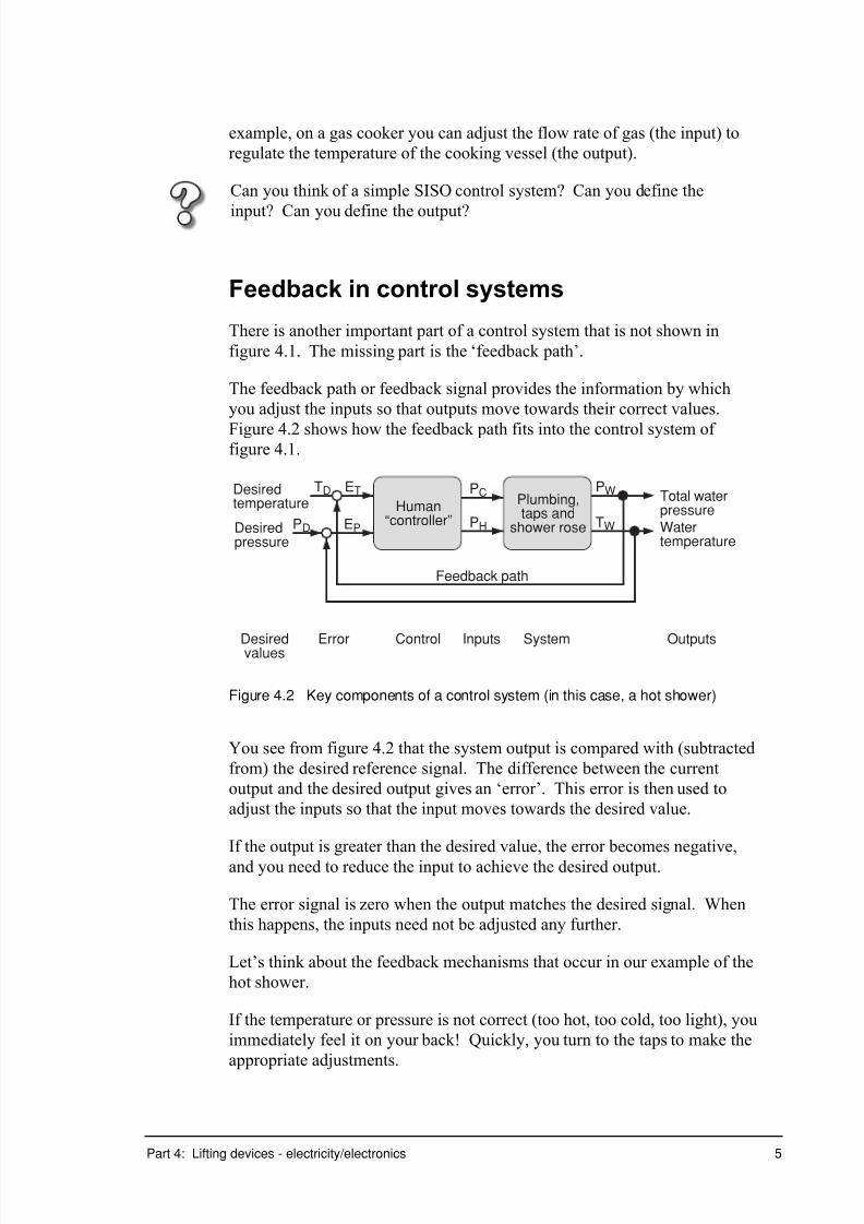
7/31/2019 3 Lifting Devices
http://slidepdf.com/reader/full/3-lifting-devices 182/281
Part 4: Lifting devices - electricity/electronics 5
example, on a gas cooker you can adjust the flow rate of gas (the input) to
regulate the temperature of the cooking vessel (the output).
Can you think of a simple SISO control system? Can you define the
input? Can you define the output?
Feedback in control systems
There is another important part of a control system that is not shown in
figure 4.1. The missing part is the ‘feedback path’.
The feedback path or feedback signal provides the information by which
you adjust the inputs so that outputs move towards their correct values.
Figure 4.2 shows how the feedback path fits into the control system of figure 4.1.
Desiredtemperature
Inputs System Outputs
Total waterpressure
TD
PH Watertemperature
PW
TW
Plumbing,taps and
shower roseDesiredpressure
PD
Human“controller”
PCET
Feedback path
ControlErrorDesiredvalues
EP
Figure 4.2 Key components of a control system (in this case, a hot shower)
You see from figure 4.2 that the system output is compared with (subtracted
from) the desired reference signal. The difference between the current
output and the desired output gives an ‘error’. This error is then used to
adjust the inputs so that the input moves towards the desired value.
If the output is greater than the desired value, the error becomes negative,
and you need to reduce the input to achieve the desired output.
The error signal is zero when the output matches the desired signal. When
this happens, the inputs need not be adjusted any further.
Let’s think about the feedback mechanisms that occur in our example of the
hot shower.
If the temperature or pressure is not correct (too hot, too cold, too light), you
immediately feel it on your back! Quickly, you turn to the taps to make the
appropriate adjustments.

7/31/2019 3 Lifting Devices
http://slidepdf.com/reader/full/3-lifting-devices 183/281
6 Lifting devices
In this case the outputs are measured, or sensed, by the human body. The
desired, or reference, signal against which you compare the output does not
exist as a physical quantity: it is actually our brain that determines what the
ideal water temperature should be. In this context you see that the human
mind/body is an integral part of the shower control system.
The human body is, in fact, a very, very good system controller. Humans
can control systems that are very difficult, if not impossible, for a machine
to manage.
Let’s think about driving a car. With some training, many humans can drive
a car. This involves controlling many interacting inputs and outputs, with
many forms of sensing being required, and many desired outputs to be
achieved simultaneously.
Inputs in a car's control system include steering, accelerator, brake, gears,windscreen wipers, indicators, radio volume and so on. The system outputs
are the speed and position of the car on the road (hopefully!), the
acceleration rate of the car, the cleanliness of the windscreen, volume of the
radio and so on.
Figure 4.3 A highly complicated system to control – a car
It would be virtually impossible to write equations that related all of the
system inputs to the system outputs for control of a motor vehicle. Without
such a set of equations it is extremely difficult to design a machine to drive a
car. Yet many of us can manage it without undue difficulty.
You will see in subsequent examples that humans form an integral part of
many motor control systems.

7/31/2019 3 Lifting Devices
http://slidepdf.com/reader/full/3-lifting-devices 184/281

7/31/2019 3 Lifting Devices
http://slidepdf.com/reader/full/3-lifting-devices 185/281

7/31/2019 3 Lifting Devices
http://slidepdf.com/reader/full/3-lifting-devices 186/281
Part 4: Lifting devices - electricity/electronics 9
Types of control systems
Analogue control
The example of the hot shower is one in which you exercise continuous, or
analogue, control over the input variables.
In Part 4 of Personal and public transport you have already used the term
analogue to describe a signal that is continuous in amplitude. In using the
term ‘analogue control’, you refer to a system in which the inputs and
outputs are continuously variable – that is, you can make arbitrarily small
adjustments to the input variables to achieve arbitrarily small changes to the
outputs. The input and output signals are said to be ‘analogue signals’.
Digital control (or switching)
In some control systems, the inputs and outputs are not analogue signals, but
instead take on only a finite number of possible values. This is equivalent to
a digital signal.
Perhaps the most simple example of a digital control system is an electric
light. The input to the system is the light switch (which controls voltage or
current) and the output is the intensity of illumination. In most instances theinput can take only one of two possible values: on or off. (You may
recognise this as a binary system). The corresponding light output is either
illumination, or no illumination.
Another example might be a ceiling fan. Many ceiling fans have two or
three speeds that can be selected to give varying levels of air circulation.
Systems that are regulated by inputs with only a finite number of possible
values are called digital or switched control systems. Note that the use of
the term digital does not (necessarily) imply logical operations (as seen in
digital logic circuits) but rather that the control system is operating withinputs and outputs that can only take on one of a finite set of values.
Can you think of an electrical appliance that has an analogue control
system? Can you think of an electrical appliance that has a digital or
switching control system?
In each case, identify the input/s and output/s of the system.
Turn to the exercise section and complete Exercise 4.1 questions 5 to 7.

7/31/2019 3 Lifting Devices
http://slidepdf.com/reader/full/3-lifting-devices 187/281
10 Lifting devices
Analogue (Continuous) control of motors
In this section you investigate analogue, or continuous, control of various
types of electric motors. You are interested in identifying how you canregulate the speed, torque and/or position of the motors using particular
inputs.
The general configuration of an electrical machine was shown in figure 4.26
of Part 4 of Transport systems, and is reproduced here as figure 4.4.
Torque
Figure 4.4 A generic electrical machine to produce torque
The figure shows two electromagnets whose fields interact to produce
torque on the rotor. You have seen in previous work that the torque produced by the machine is given by:
q S i n N I N I T S S R R ¥¥µ
where
I R and I S are the currents in the rotor and stator coils respectively;
N R and N
S are the number of turns on the rotor and stator coils
respectively; and
q is the angle between the two magnetic fields.
Control of DC motors
The general configuration of a DC machine was seen previously in figure
4.32 of Part 4 of Transport Systems. You saw there that the commutator
structure of the DC machine fixed the angle between the rotor and stator
fields at 90°. This angle maximises the torque produced, since Sin q is at a
maximum when q = 90°

7/31/2019 3 Lifting Devices
http://slidepdf.com/reader/full/3-lifting-devices 188/281
Part 4: Lifting devices - electricity/electronics 11
The torque produced by a DC machine is thus:
S S R Rd c N I N I T ¥µ
The number of turns on the stator and rotor coils of a DC machine areinvariably fixed by the manufacturer of the motor. This means that the
variables N R and N S cannot be used (by us) for controlling the motor torque.
Consequently, the torque produced by the DC motor is described by the
more simple expression:
S Rd c I I T ¥µ
That is, the torque produced by the motor is simply proportional to the
product of the rotor and stator currents.
It is common to keep the stator current in a DC motor constant. (This meansthat the stator’s magnetic field is constant.) This is simply achieved by
feeding the stator coils with a constant DC voltage source. See figure 4.5.
DC sourceVS
Figure 4.5 Stator of a DC machine fed by a constant voltage source, givingconstant stator current
The stator current in this case is determined by:
I V
RS
S
S
=
where V S is the stator source voltage and RS is the stator winding resistance.
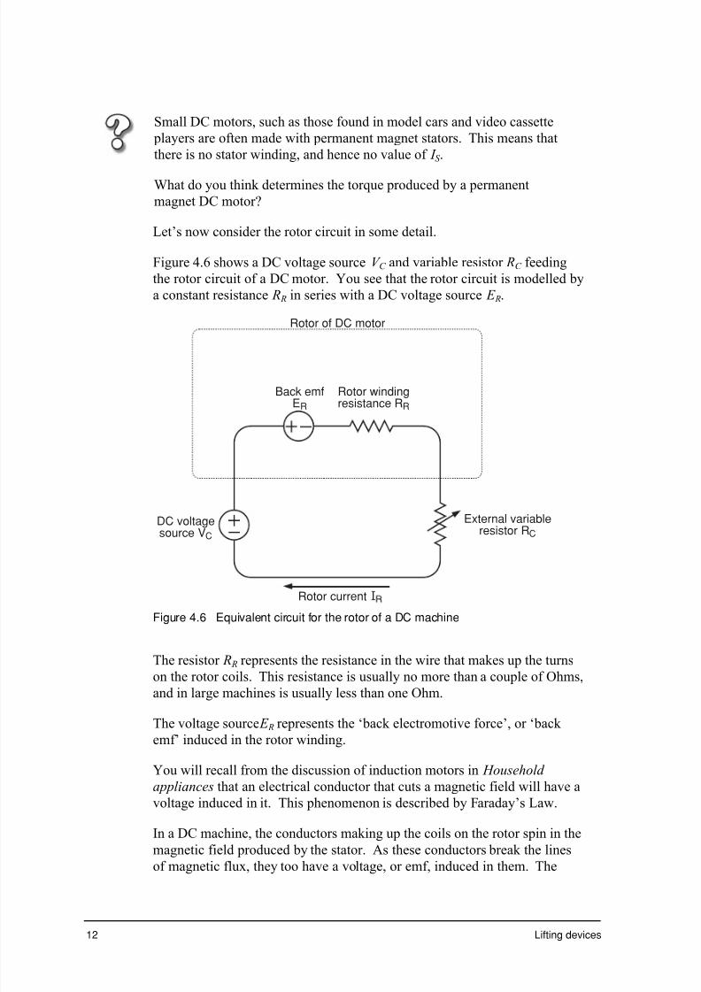
7/31/2019 3 Lifting Devices
http://slidepdf.com/reader/full/3-lifting-devices 189/281
12 Lifting devices
Small DC motors, such as those found in model cars and video cassette
players are often made with permanent magnet stators. This means that
there is no stator winding, and hence no value of I S .
What do you think determines the torque produced by a permanent
magnet DC motor?
Let’s now consider the rotor circuit in some detail.
Figure 4.6 shows a DC voltage source V C and variable resistor RC feeding
the rotor circuit of a DC motor. You see that the rotor circuit is modelled by
a constant resistance R R in series with a DC voltage source E R.
Rotor of DC motor
Back emfER
External variableresistor RCDC voltagesource VC
Rotor current
Rotor windingresistance RR
Figure 4.6 Equivalent circuit for the rotor of a DC machine
The resistor R R represents the resistance in the wire that makes up the turns
on the rotor coils. This resistance is usually no more than a couple of Ohms,
and in large machines is usually less than one Ohm.
The voltage source E R represents the ‘back electromotive force’, or ‘back
emf’ induced in the rotor winding.
You will recall from the discussion of induction motors in Household
appliances that an electrical conductor that cuts a magnetic field will have a
voltage induced in it. This phenomenon is described by Faraday’s Law.
In a DC machine, the conductors making up the coils on the rotor spin in the
magnetic field produced by the stator. As these conductors break the lines
of magnetic flux, they too have a voltage, or emf, induced in them. The

7/31/2019 3 Lifting Devices
http://slidepdf.com/reader/full/3-lifting-devices 190/281

7/31/2019 3 Lifting Devices
http://slidepdf.com/reader/full/3-lifting-devices 191/281
14 Lifting devices
Figure 4.7 shows the electrical connections for a DC machine to enable
torque control.
DC sourceVs
External variableresistor RC
DC voltagesource VC
Figure 4.7 Electrical connections for controlling a DC motor
Implementing either of these two control strategies allows us to control the
torque produced by the motor. The speed or position of the motor is
generally much more difficult to control, since these outputs are dependent
on the nature of the load attached to the motor.
Figure 4.8 shows the DC machine from a control system perspective.
Rotor source voltage
Inputs System Outputs
DC motor
Rotor resistance
Motor torque
VC
RC
TDC
Figure 4.8 Control system view of a DC machine
In many instances, the control of speed or position is left to a ‘human
controller’.
For example, an electric train lifting a load of passengers up the Blue
Mountains is driven by a human. The driver makes adjustments to themotor (rotor) current which varies the torque produced by the machine.

7/31/2019 3 Lifting Devices
http://slidepdf.com/reader/full/3-lifting-devices 192/281
Part 4: Lifting devices - electricity/electronics 15
However, the torque produced by the motors is not the important output
variable. The speed and position are more significant: these outputs are the
result of the good judgement of the driver who instinctively varies the
torque to achieve the desired speed and position.
Similarly, a crane driver uses experience and his observations to control the
lifting of very light or very heavy loads, using only the rotor current to
regulate the torque of the winch motor.
An example where direct human intervention is not used is that of a modern
elevator. In an elevator, there is no ‘driver’ using observations and
judgement to control the vehicle. (There was, of course, in older style
elevators.) Instead, the control of the vehicle is handled by a sophisticated
automated system.
The automated system needs to sense where passengers are located (bymonitoring push buttons on respective floors) and where they want to go (by
monitoring push buttons inside the vehicle). Using this information,
together with measurements of vehicle speed and position, the controller
regulates the motor (rotor) current to achieve the desired outputs.
Can you think of an example where a DC motor is used in an appliance or
toy in your home? Is the speed of the motor variable? Who or what
controls the motor speed?
Turn to the exercise section and complete exercise 4.1 questions 8 to 10.
Control of synchronous motors
You have previously read about the principles of synchronous motors.
While synchronous motors are not often used in lifting devices, it is
insightful to contrast their control characteristics with those of the DC
machine examined above.
The stator of a synchronous motor is usually fed by a three-phase supply to
produce a rotating magnetic field. (See Part 4 figure 4.29 of Personal and
public transport .) The key parameter of this supply is its frequency.
You might recall from previous work that the speed of a synchronous motor
is determined by the speed of rotation of the stator field. This means that if
the stator field is supplied by a fixed frequency source (such as mains
electricity) then the speed of the motor is also fixed. If you change the
supply frequency, you can change the speed of the motor.
In order to vary the speed of the machine you must be able to provide a
variable frequency supply to the synchronous motor's stator. In practice the
complexity, and hence cost, of this arrangement discourages its use.

7/31/2019 3 Lifting Devices
http://slidepdf.com/reader/full/3-lifting-devices 193/281
16 Lifting devices
Consequently, synchronous motors are generally only used in constant
speed applications.
The torque produced by a synchronous motor is again determined by:
q S i n N I N I T S S R R ¥¥µ
where
I R and I S are the currents in the rotor and stator coils respectively;
N R and N S are the number of turns on the rotor and stator coils
respectively; and
q is the angle between the two magnetic fields.
In the synchronous motor case, the stator current I S is usually fixed (by the
stator supply voltage V S and stator winding resistance RS , with I V
R S
S
S
= ).
N S and N R are fixed by the motor manufacturer.
In the case of the DC motor, you saw that the torque and speed are related
by the nature of the load and not by the motor itself. For example, a heavy
load requires greater torque for a given speed than does a light load.
In the synchronous motor, the torque and speed are determined by separate
quantities inside the motor: the torque is determined by I R ¥ Sin q ; the
speed is determined by the frequency of the AC supply.
However, you know from physics that the torque and speed must be
matched for a given load.
So how does the synchronous motor ensure that the appropriate torque is
produced for a given load and speed?
The answer is in the Sinq term. The angle q is defined as the angle between
the stator and rotor magnetic fields. This angle can vary between 0o (zerotorque) and 90o (maximum torque). The angle q is not an input variable that
you can control – it is a variable that automatically adjusts itself to match
the torque required by the load.
When the load is relatively light, q adjusts to a small angle, and only a small
torque is produced by the motor. When the load increases, q also increases
towards 90o.
If the load is too heavy for the machine, the angle increases beyond 90o.
The resulting torque then decreases (because of the Sinq term). The motor
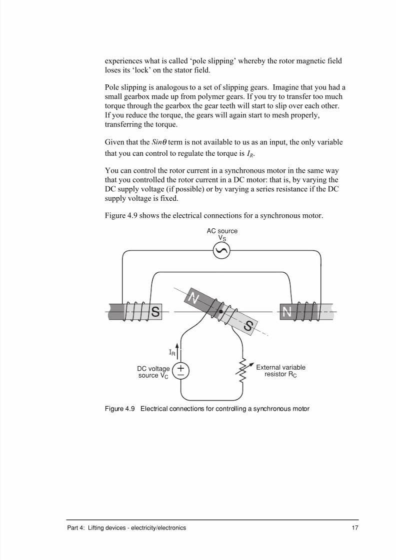
7/31/2019 3 Lifting Devices
http://slidepdf.com/reader/full/3-lifting-devices 194/281
Part 4: Lifting devices - electricity/electronics 17
experiences what is called ‘pole slipping’ whereby the rotor magnetic field
loses its ‘lock’ on the stator field.
Pole slipping is analogous to a set of slipping gears. Imagine that you had a
small gearbox made up from polymer gears. If you try to transfer too muchtorque through the gearbox the gear teeth will start to slip over each other.
If you reduce the torque, the gears will again start to mesh properly,
transferring the torque.
Given that the Sinq term is not available to us as an input, the only variable
that you can control to regulate the torque is I R.
You can control the rotor current in a synchronous motor in the same way
that you controlled the rotor current in a DC motor: that is, by varying the
DC supply voltage (if possible) or by varying a series resistance if the DC
supply voltage is fixed.
Figure 4.9 shows the electrical connections for a synchronous motor.
AC sourceVS
External variableresistor RC
DC voltagesource VC
Figure 4.9 Electrical connections for controlling a synchronous motor
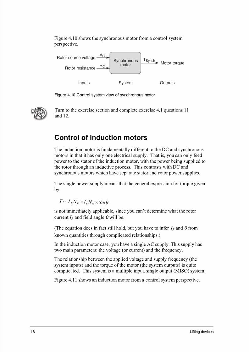
7/31/2019 3 Lifting Devices
http://slidepdf.com/reader/full/3-lifting-devices 195/281
18 Lifting devices
Figure 4.10 shows the synchronous motor from a control system
perspective.
Rotor source voltage
Inputs System Outputs
SynchronousmotorRotor resistance
Motor torque
VC
RCTSynch
Figure 4.10 Control system view of synchronous motor
Turn to the exercise section and complete exercise 4.1 questions 11
and 12.
Control of induction motors
The induction motor is fundamentally different to the DC and synchronous
motors in that it has only one electrical supply. That is, you can only feed
power to the stator of the induction motor, with the power being supplied to
the rotor through an inductive process. This contrasts with DC and
synchronous motors which have separate stator and rotor power supplies.
The single power supply means that the general expression for torque given by:
q S i n N I N I T S S R R ¥¥µ
is not immediately applicable, since you can’t determine what the rotor
current I R and field angle q will be.
(The equation does in fact still hold, but you have to infer I R and q from
known quantities through complicated relationships.)
In the induction motor case, you have a single AC supply. This supply hastwo main parameters: the voltage (or current) and the frequency.
The relationship between the applied voltage and supply frequency (the
system inputs) and the torque of the motor (the system outputs) is quite
complicated. This system is a multiple input, single output (MISO) system.
Figure 4.11 shows an induction motor from a control system perspective.

7/31/2019 3 Lifting Devices
http://slidepdf.com/reader/full/3-lifting-devices 196/281
Part 4: Lifting devices - electricity/electronics 19
Source voltage
Inputs System Outputs
Synchronousmotor
Source frequency
Motor torque
VS
FS
TInduct
Figure 4.11 Control system view of an induction motor
In practice, you use induction motors in either a controlled, or uncontrolled,
form.
In a controlled form, you need Variable Voltage Variable Frequency
(VVVF) drive system. This is essentially a box of electronics that converts
a fixed frequency fixed voltage supply (from the mains) into a supply that
has adjustable voltage and frequency. These systems are invariablymicroprocessor controlled, and allow us to vary the torque, and hence speed,
of an induction motor.
Unfortunately, VVVF drives are relatively expensive. Thus while induction
motors are relatively cheap amd robust, the addition of a VVVF controller
detracts from the motor's inherent advantage.
In an uncontrolled form, you simply apply a fixed frequency fixed voltage
(from the mains) to the motor. The motor then runs at a speed dictated by
the nature and size of the load.
Obviously uncontrolled motors are much cheaper to use that controlled
motors. The uncontrolled form is actually very common: refrigerators,
washing machines, fans and pumps can all run uncontrolled. The maximum
speed of the induction motor is limited by its supply frequency, and so
induction motors connected to the mains cannot run at excessive speed.
Induction motors make up a large part of the total electrical load of the state.
By far the majority of these motors are uncontrolled!
How many induction motors do you think there may be in and around
your home?
Make a list of the devices that you think contain induction motors.
___________________________________________________________
___________________________________________________________
Did you answer?
Some of the appliances which may contain induction motors include: air
conditioner; washing machine; electric crane and electric lifts.

7/31/2019 3 Lifting Devices
http://slidepdf.com/reader/full/3-lifting-devices 197/281
20 Lifting devices
Are any of these motors controlled by VVVF drives?
Turn to the exercise section and complete exercise 4.1 questions 13 to 14.
Motor control summary
The following table shows a summary of the key parameters for control of
various motor types.
Motor Type NormallyFixed Inputs
ControllableInputs
ControlledOutputs
Notes
DC motor N R , N S , I S ,Sin q
I R T DC Max speed limitedby back emf.Speed set by load.
Synchronousmotor
N R , N S , I S I R T synch Speed set bystator supplyfrequency. Sin q
self adjusting toload.
Inductionmotor
N R , N S V S , frequencyof supply F S
T Induct Max speed limitedby supplyfrequency. Speedset by load.

7/31/2019 3 Lifting Devices
http://slidepdf.com/reader/full/3-lifting-devices 198/281
Part 4: Lifting devices - electricity/electronics 21
Digital (Switching) control of electric motors
In the above you have looked at analogue control of DC, synchronous andinduction motors. In these instances you saw you can control the speed
and/or torque of the various motors by continuously variable voltages,
currents, resistances and/or frequencies.
While analogue systems offer very good control of motor performance, such
systems are becoming increasingly expensive, particularly in comparison
with alternatives based on digital devices.
Digital technology is based on a simple on-off switching arrangement. The
approach is simple, cheap, and as you will see, can be very effective.
On-Off (Binary) switching
The concept of switching is simple and familiar to us all. Every day you
switch many devices on and off as you require.
Most of the time, the time lapse between switching on and off varies from a
few seconds to several or many hours. For example, you might use a food
processor for ten seconds at a time; a hair dryer for minutes at a time, and
room lighting for hours at a time.
In some appliances the motor is switched automatically by the appliance's
control system. For example, in a refrigerator, a thermostat monitors the
temperature inside the fridge. If the temperature rises above a preset
threshold, the cooling system (compressor) motor is switched on until such
time as the fridge cools to its correct operating range.
Another example of an automated motor drive is a garage door opener.
Usually you press a switch (on the wall or on a remote controller) to start the
door opening or closing. However, the motor stops driving when the door is
fully open or closed without our intervention. Sensors are used to detectwhen the door is fully open or fully closed and to cut power to the motor
when these limits are reached.
Can you draw a control system diagram for an automatic garage door
when it is closing? What are the system inputs? What are the outputs?
What is the desired setting? How can you generate an error signal?

7/31/2019 3 Lifting Devices
http://slidepdf.com/reader/full/3-lifting-devices 199/281
22 Lifting devices
Pulse Width Modulation (PWM)
Switching control of electric motors is not limited to those applications
when the time between switching is several seconds, minutes or hours.
Many new technologies use a control strategy that switches a device on and
off many times per second in order to emulate a continuously variable, or
analogue, signal. Such systems are often called Pulse Width Modulation, or
PWM, systems.
Suppose you have a single electric lamp in a darkened room.
If the lamp is off, the room is totally dark.
If the lamp is turned on (and left on) we'll say that the room is totally bright.
Now suppose you were able to turn the lamp on and off at around 1 000
times per second. (Don't worry for the moment as to how you could operate
a switch so rapidly, we'll just assume it can be done!)
If the lamp is on for 1 millisecond, and then off for one millisecond, then on
again for one millisecond, off for one millisecond, and so on, the room
would only be half as bright as compared to when the lamp was on all of the
time. This is because only half the amount of light energy is being delivered
into the room.
During this switching, our eyes would not be able to tell that the lamp wasflashing. Our eyes can only detect flicker frequencies up to ten or twenty
Hertz.
(Films shown at the cinema are actually a series of still images, updated at
24 frames per second (24 Hz). Our eyes are not sufficiently sensitive to see
the individual images, hence the resulting image is perceived as one of
continuous motion.)
Suppose now that you turned the lamp on for one millisecond, then off for
three milliseconds, then on for one millisecond, off for three milliseconds,
and so on. The room now is only one quarter as bright as if the lamp wasfully on.
It is clear that you can vary the ratio of on-time to off-time to vary the
average brightness.
The ratio of on-time to off-time is called the ‘duty cycle’ and is measured as
a percentage:
% Duty Cycle(on - time)
(on - time) off - time)=
+¥
(100
By varying the duty cycle, you can in effect approximate an analogue signal.

7/31/2019 3 Lifting Devices
http://slidepdf.com/reader/full/3-lifting-devices 200/281

7/31/2019 3 Lifting Devices
http://slidepdf.com/reader/full/3-lifting-devices 201/281
24 Lifting devices
Time varying pulse width modulation
In the above discussion you assumed that the duty cycle remained constant,
and hence the average output remained constant.
The duty cycle can be made time varying. Varying the duty cycle allows
you to produce a time varying ‘average’ signal. (The term ‘average’ here is
used in inverted commas because you now have to be careful over what
period you do your averaging.) Figure 4.13 shows the effect of varying the
duty cycle in a particular pattern so as to produce a sinusoidally varying
signal.
On
Off
Equivalent (sinusoidal)analogue output
Pulse with modulated output
Switchposition
Figure 4.13 Sinusoidal signal produced by a time varying PWM cycle
Turn to the exercise section and complete exercise 4.1 questions 15 to 16.
Applications of motor control in liftingdevices
In considering motor control in the context of lifting devices, you will try to
categorise the system according to a number of key parameters:
• Motor type – does it use a DC motor, synchronous motor or inductionmotor?
• Is the motor controlled in some sense, or is it simply on/off?
• If controlled, what are the controllable inputs, and what are the
controlled outputs?
• Does the system use automatic feedback, or does it rely on human control?
Electric motors are used in many lifting applications. You will consider a
small number of applications here.

7/31/2019 3 Lifting Devices
http://slidepdf.com/reader/full/3-lifting-devices 202/281
7/31/2019 3 Lifting Devices
http://slidepdf.com/reader/full/3-lifting-devices 203/281
26 Lifting devices
Brick conveyor
A brick conveyor is used to haul individual bricks from ground level up one
or two floors on small building sites on a conveyor belt.
The belt is started with no bricks on it, and then bricks are placed on the
conveyor. This means that the conveyor can start with virtually no load, but
once under way, the load is steadily increased.
• Motor type – does it use a DC motor, synchronous motor or induction
motor?
You would like the motor to be as robust and cheap as possible, so use
an induction motor.
• Is the motor controlled in some sense, or is it simply on/off?
System is controlled by a simple on/off arrangement. The speed of theconveyor is limited by the supply frequency (usually a mains supply),
and slows down as the load increases. Control over torque, speed or
position not really required.
Crane
• Motor type - does it use a DC motor, synchronous motor or induction
motor?
Need variable speed, and high starting torque, so DC or VVVF-fed
induction motor best suited.• Is the motor controlled in some sense, or is it simply on/off?
Motor needs to be closely controlled to allow accurate placement of loads.
• If controlled, what are the controllable inputs, and what are the
controlled outputs?
The main output to be controlled is the position of the load. This
position is closely related to the speed and duration of lift. The speed of
lift is, in turn, dependent on the torque produced by the motor which is
a function of the motor current.
• Does the system use automatic feedback, or does it rely on humancontrol?
The system is highly dependent on skilled operators to translate desired
position into a combination of speed and duration of lift.
Can you categorise the following applications according to the criteria abo
• A motorised garage door opener?
• A constant speed escalator in a shopping mall?
Turn to the exercise section and complete exercise 4.2a to f.

7/31/2019 3 Lifting Devices
http://slidepdf.com/reader/full/3-lifting-devices 204/281

7/31/2019 3 Lifting Devices
http://slidepdf.com/reader/full/3-lifting-devices 205/281
28 Lifting devices
Employers (OH&S Act Section 15)
Employers are responsible for ensuring the health, safety and welfare of
their employees. Employers must ensure that hazard identification and risk
assessments have been done, control measures applied, and safe working practices put in place, before starting work.
All of these precautions must be reviewed on an ongoing basis.
What type of safety measures might you (as an employer) provide if you
expected one of your employees to work (safely) on a roof?
Employers and self employed persons (OH&S ActSection 16)
Employers and self employed people must ensure the health and safety of
people visiting the workplace who are not their employees. This covers all
types of visitors, such as passers by, or likely visitors to each work site.
Why do you think high rise building sites are often cloaked in mesh or
cloth screens? Why would you bother to board up or fence off a building
site in a shopping centre when it would be much easier not to do this?
Supervisors (OH&S Act Section 15)
Supervision is the process of providing guidance and training. An employer
is required to provide whatever supervision may be necessary. The level of
supervision is determined by the need to ensure the work is done safely.
Employees (OH&S Act Section 19)
Employees must comply with any safety procedures prescribed by the
employer. This includes correct use and maintenance of personal protective
equipment, special tools or related safety gear. The employee is also
expected to identify and report workplace hazards as they become known to
ensure they are addressed.
Duty of care
Under the Act, everyone, not just employers and supervisors have a
responsibility not only for their own health and safety while at work, but a
‘duty of care’ for the health and safety of others.
If you noticed an unsafe work practice by a work or school colleague, or
found a dangerous or faulty piece of equipment, what do you think your ‘duty of care’ requires you to do?

7/31/2019 3 Lifting Devices
http://slidepdf.com/reader/full/3-lifting-devices 206/281
Part 4: Lifting devices - electricity/electronics 29
Australian standards
The Australian Standards are a large collection of documents that cover
an enormous variety of situations. They prescribe what precautions andmeasures are considered appropriate for anything from paint and building
materials through to electrical appliances. Almost any device, product or
service you can think of is likely to have some components subject to an
Australian Standard.
There are a large number of Standards documents that relate to electrical
equipment and installations. Some of these include:
• AS 3000 – 1994: Electrical installations – buildings, structures and
premises (SAA Wiring Rules).
• AS 2243.7 – 1991: Safety in laboratories Part 7: Electrical aspects,electrical safety in the workplace.
• AS 1674.2 – 1990: Safety in welding and allied processes Part 2:
Electrical.
• AS 3003 – 1999: Electrical installations - patient treatment areas of
hospitals and medical and dental practices.
• AS/NZS 3760 – 1996: In-service safety inspection and testing of
electrical equipment.
These documents prescribe anything from the distance a power point
must be located away from a source of water, to how deep an electricalcable must be buried in the ground. The standards change regularly as
new equipment and methods evolve.
Hazard assessments
Hazard assessment is the process of identifying all the hazards that are
present in a particular working area. These are prioritised in order of
seriousness of potential injury arising from each hazard, from fatal through
to minor injury.
Having listed all of the identified hazards and assessed their potential
severity, the next step is to estimate the exposure: that is the number of
times and/or the length of time in which a worker is exposed to each hazard.
A combination of long or frequent exposure and the possibility of severe
injury would mean the hazard should be placed high on the priority list.
The purpose of prioritising the hazards is only for the order of addressing
them. All hazards must be considered, irrespective of risk. The combination
of potential injury and level of exposure determines the level of risk.

7/31/2019 3 Lifting Devices
http://slidepdf.com/reader/full/3-lifting-devices 207/281

7/31/2019 3 Lifting Devices
http://slidepdf.com/reader/full/3-lifting-devices 208/281

7/31/2019 3 Lifting Devices
http://slidepdf.com/reader/full/3-lifting-devices 209/281
32 Lifting devices
Building elevator
An elevator or lift in a multi storey building is another common example of
an electrical lifting device, and it too has a number of specific additionalsafety features. Commonly the lift is driven up and down by an electric
motor connected through a mechanical gear box and system of steel cables
and counter weights.
Just as with the garage door opener, a lift also automatically detects objects
(or people) caught between its doors as they attempt to close. This can be
done by detecting the door closer current or by a switch bar which contacts
the obstacle before the door does. On detection of an obstacle the door
automatically reverses.
Again, once the doors are closed, what happens if something goes wrong?What happens if there is a power failure with people in the lift?
A lift commonly does not have windows, so in the event of power failure,
the lift is likely to be particularly dark. Lifts (and indeed buildings in
general) will often have an emergency lighting system. A small light,
usually powered by a small battery, automatically comes on if the ambient
light levels fall below a certain threshold or the mains power is removed.
When the mains are operating normally, the battery is kept charged.
Many power failures are relatively short in duration, but what if the power is
off for a significant length of time?
People in the lift will need to be able to contact someone outside for help.
Most elevators contain either an alarm, that can be triggered by people in the
lift to alert those outside to their plight, or a telephone.
Most telephone systems are actually battery powered for this very reason.
Ever noticed that during a power blackout, your telephone at home will still
work?
The telephone network is powered by a large bank of batteries that are kept
charged at your local exchange.
What about the lift drive system itself? What happens if the motor or control
system malfunctions?
Many elevators contain additional safety devices for the event of the hoist
system failing. There are sometimes redundant hoist systems, safety cables,
automated detection of cable breakages, or slack cables, manual overrides to

7/31/2019 3 Lifting Devices
http://slidepdf.com/reader/full/3-lifting-devices 210/281
Part 4: Lifting devices - electricity/electronics 33
open doors or to control the elevator hoists directly in the event of a control
system failure.
Elevators and other building electrical systems are often interlocked with a
building fire alarm. Elevator doors will permanently open if the fire alarmis triggered and the lift disabled. Air conditioning systems will often switch
off to prevent smoke from a fire circulating through the building.
Turn to the exercise section and complete exercise 4.3.

7/31/2019 3 Lifting Devices
http://slidepdf.com/reader/full/3-lifting-devices 211/281

7/31/2019 3 Lifting Devices
http://slidepdf.com/reader/full/3-lifting-devices 212/281

7/31/2019 3 Lifting Devices
http://slidepdf.com/reader/full/3-lifting-devices 213/281

7/31/2019 3 Lifting Devices
http://slidepdf.com/reader/full/3-lifting-devices 214/281
Part 4: Lifting devices - electricity/electronics 37
11 A synchronous motor can be made to run at variable speed by:
a varying the magnitude of the stator current
b varying the magnitude of the rotor current
c varying the frequency of the stator current
d varying the frequency of the rotor current.
12 Pole slipping in a synchronous machine results from:
a insufficient motor torque to match the given load
b too much motor torque for the given load
c too much grease on the motor shaft
d incorrect meshing of polymer gears.
13 An induction motor:
a has separate stator and rotor power supplies
b uses one power supply connected to both stator and rotor
c doesn't need any power in the rotor
d induces power in the rotor as described by Faraday's Law.
14 An induction motor connected directly to the mains supply will:
a not run at all
b run at a fixed speed
c run at a speed determined by the size and nature of the load
d cause a short circuit and catch fire.
15 PWM is an abbreviation of:
a perfectly wound motor
b perfect width motor
c pulse width modulation
d precisely weighted magnets
16 The principal use of PWM in control systems is to:
a emulate analogue control using switching devices
b blind people with flickering lights
c feature electric motors in cinematography
d confuse Engineering Studies students.

7/31/2019 3 Lifting Devices
http://slidepdf.com/reader/full/3-lifting-devices 215/281

7/31/2019 3 Lifting Devices
http://slidepdf.com/reader/full/3-lifting-devices 216/281
Part 4: Lifting devices - electricity/electronics 39
Exercise 4.2
Suppose you are engaged as an engineering consultant to oversee the design
of a moving walkway to be installed in a new international airport. The
proposed walkway is quite long (around 200 metres) and should run at aconstant speed in normal operation.
In considering the following factors, state any assumptions you make about
the walkway, its design or about the people who will use it.
a State the number of electric motors that should be used to power the
walkway and justify the reason for your proposed selection
______________________________________________________
______________________________________________________
______________________________________________________ b Indicate the type/s of motors that should be used for this application and
explain the reason for your choice of these particular motor types.
______________________________________________________
______________________________________________________
______________________________________________________
c State how many output parameters do you need to control in terms of a
control system.
______________________________________________________ ______________________________________________________
d List the input variables do you need to control the motors to achieve the
desired outputs.
______________________________________________________
______________________________________________________
e Indicate if the control system should be fully automatic, or employ
skilled operators to control the walkway.
______________________________________________________ f Indicate if you propose to use analogue or digital techniques to
implement your controller and explain the reasons underlying your
decision.
______________________________________________________
______________________________________________________
______________________________________________________

7/31/2019 3 Lifting Devices
http://slidepdf.com/reader/full/3-lifting-devices 217/281
40 Lifting devices
Exercise 4.3
a Identical who is responsible for the safety of the passengers on the
moving walkway.
_______________________________________________________ b Indicate if you propose to schedule regular and/or routine maintenance
as an integral component of your safety regime and outline maintenance
or checking would you specify.
_______________________________________________________
_______________________________________________________
_______________________________________________________
c Explain how your system should react if too many people crowd on the
walkway overloading it.
_______________________________________________________
_______________________________________________________
_______________________________________________________
d Outline the options that should be available to stop the walkway in case
of an emergency.
_______________________________________________________
_______________________________________________________
_______________________________________________________

7/31/2019 3 Lifting Devices
http://slidepdf.com/reader/full/3-lifting-devices 218/281

7/31/2019 3 Lifting Devices
http://slidepdf.com/reader/full/3-lifting-devices 219/281
42 Lifting devices

7/31/2019 3 Lifting Devices
http://slidepdf.com/reader/full/3-lifting-devices 220/281

7/31/2019 3 Lifting Devices
http://slidepdf.com/reader/full/3-lifting-devices 221/281
Arial Arial bold
Lifting devices
Part 5: Lifting devices –communication

7/31/2019 3 Lifting Devices
http://slidepdf.com/reader/full/3-lifting-devices 222/281

7/31/2019 3 Lifting Devices
http://slidepdf.com/reader/full/3-lifting-devices 223/281

7/31/2019 3 Lifting Devices
http://slidepdf.com/reader/full/3-lifting-devices 224/281
Arial Arial bold
Part 5: Lifting devices – communication 3
Orthogonal projection, AS 1100 standards
Representation of repeated features
When a component contains a regular pattern of repeated features such as
holes or slots, the AS 1100 standard allows these repeated features to beshown as full outline of all of the features or alternatively by a
conventional representation.
Using the conventional representation, one of the holes or slots may be
shown in full outline, and the position of the remainder by centrelines.
The number and size of the holes or slots must be indicated using a note
and leader line.
The method of conventional representation is far quicker to use and also
makes the drawing much simpler. The advantage in using this standard
is a great saving of time, especially in your HSC examination.
Figures 5.01 and 5.02 show the true representation then the conventional
representation of eight drilled and counterbored holes in a circular
locking cap.

7/31/2019 3 Lifting Devices
http://slidepdf.com/reader/full/3-lifting-devices 225/281
4 Lifting devices
4 8 6
60
ON 40 PCD
Figure 5.1 True drawing of the top view of the circular locking cap
4 8 68 x
60
40
5
2 5
20
Figure 5.2 Conventional representation of repeated features
7/31/2019 3 Lifting Devices
http://slidepdf.com/reader/full/3-lifting-devices 226/281
Arial Arial bold
Part 5: Lifting devices – communication 5
What do the drawings convey to you? What does the dimensioning
mean? Which drawing is the quicker and easier to draw?
While you are considering each drawing you should revise the AS 1100standards used in the drawings; the use of a half-section, the use of full
dimensioning, the standard dimensioning methods and the use of a detail
drawing. These will all be used in Exercise 5.1.
Consider the two views of the circular locking cap and the dimensioning
of the holes. Both top views show a regular pattern of eight,
counterbored, through holes of diameter four millimeter, counterbored
diameter eight millimeters to a depth of six millimeters.
Figure 5.1 shows the true representation of the repeated features,
dimensioned using the symbol methods from AS 1100.101-1992. You
should revise this dimensioning work from your previous module. The
reason for the use of symbols when dimensioning is to avoid the use of
written language, and also to make the drawing simpler to read and
quicker to draw.
Similarly, the conventional representation of the repeated features in the
top view in figure 5.2 makes the drawing simpler to read and quicker to
draw.
To save you time you should learn the standards for this conventional
representation of repeated features. Remember that you must use a note
and leader line to indicate the number of holes or features and the
dimensions required for those holes or features.
Preparing for Exercise 5.1
The following section explains the approach you should use when
attempting Exercise 5.1. You should read the section and then attempt
the exercise. You should also be aware that the exercise number is
shown in the title block for each exercise, not at the top of the page.
Look at Exercise 5.1.
The exercise requires you to draw to a scale of 1:1, a detail drawing of
the Screw Jack Head. You are required to use a top view, incorporating
the conventional representation for repeated features, a half-sectioned
front view, and to completely dimension the drawing.
Your first step should be to consider the shape and size details given on
the drawing. The screw jack head is circular in shape, the top is diameter
75 mm and has twelve 5 mm x 3 mm grooves. The head has a through
25 mm hole, counterbored 36 mm to a depth of 8 mm. A radius of 25
7/31/2019 3 Lifting Devices
http://slidepdf.com/reader/full/3-lifting-devices 227/281

7/31/2019 3 Lifting Devices
http://slidepdf.com/reader/full/3-lifting-devices 228/281
7/31/2019 3 Lifting Devices
http://slidepdf.com/reader/full/3-lifting-devices 229/281
8 Lifting devices
Itemising of parts or components
Item number
An item number is a number assigned to a component on an assembly
drawing. It is used to identify components, enabling information
regarding the components to be referenced from the materials or parts
list.
Capital, that is, upper case letters may be used in addition to numbers
where necessary.
The height of the numbers should be twice the height of dimensioning
used on the drawing.
The item number should be enclosed in a circle to further differentiate itfrom any dimensioning. The circle should be drawn using thin dark lines
and a diameter equal to twice the height of the numbering.
Where no confusion would occur, the number may be drawn without the
use of a circle.
The numbers should be arranged in sequential order to assist in easy
identification of the components, and should be positioned in vertical
columns and/or horizontal rows on the drawing.
Leaders
Leaders are thin dark continuous lines drawn from the itemizing circle or
number to the component or item on the assembly drawing. They are
used to clearly identify the component.
Leaders should:
• not intersect dimension lines or other leaders
• be kept as short as possible
• be drawn at an angle to the itemizing number
• be drawn radially from the itemizing circle
• terminate in an arrow or a dot.
In assembly drawings, dots are the preferred method to be used as
terminators of leader lines. The dots should be;
• of diameter twice the thickness of the leaders they terminate, but not
less than diameter 1 mm
• within the outline of the component.
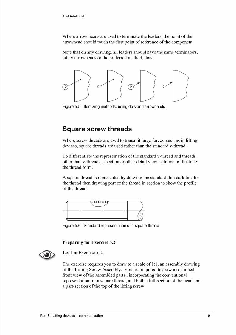
7/31/2019 3 Lifting Devices
http://slidepdf.com/reader/full/3-lifting-devices 230/281
Arial Arial bold
Part 5: Lifting devices – communication 9
Where arrow heads are used to terminate the leaders, the point of the
arrowhead should touch the first point of reference of the component.
Note that on any drawing, all leaders should have the same terminators,
either arrowheads or the preferred method, dots.
2 2 2 2
Figure 5.5 Itemizing methods, using dots and arrowheads
Square screw threads
Where screw threads are used to transmit large forces, such as in lifting
devices, square threads are used rather than the standard v-thread.
To differentiate the representation of the standard v-thread and threads
other than v-threads, a section or other detail view is drawn to illustrate
the thread form.
A square thread is represented by drawing the standard thin dark line for the thread then drawing part of the thread in section to show the profile
of the thread.
Figure 5.6 Standard representation of a square thread
Preparing for Exercise 5.2
Look at Exercise 5.2.
The exercise requires you to draw to a scale of 1:1, an assembly drawing
of the Lifting Screw Assembly. You are required to draw a sectioned
front view of the assembled parts , incorporating the conventional
representation for a square thread, and both a full-section of the head and
a part-section of the top of the lifting screw.
7/31/2019 3 Lifting Devices
http://slidepdf.com/reader/full/3-lifting-devices 231/281

7/31/2019 3 Lifting Devices
http://slidepdf.com/reader/full/3-lifting-devices 232/281
Arial Arial bold
Part 5: Lifting devices – communication 11
Preparing for Exercise 5.3
You have now completed most of the AS 1100 standards appropriate to
your Engineering Studies course. However, you need to practise the
application of these standards. Exercise 5.3 does not introduce any newstandards, but requires you to revise and apply previously covered
standards.
Look at Exercise 5.3.
The exercise requires you to draw to a scale of 1:1, an assembly drawing
of the Pulley Block Assembly. You are required to draw a sectioned
front view of the assembled parts.
Your first step again should be to consider the shape and size details
given on the drawing, and the method of assembling the components. Toassemble, the pulley is positioned inside the block and the shaft is pushed
through the diameter 20 mm holes in both the block and the pulley. The
shaft protrudes evenly on both sides of the block.
Care should be taken with the dimensions of the webs; they slope from
the top bosses, a distance of 62 mm apart, to the bottom bosses, 60 mm
apart.
Your next step is to design the drawing, completing a freehand sketch
showing the required sectional front view. Again, you should complete a
quality freehand drawing as practice for your HSC.
Turn to the exercise sheets and complete exercise 5.3 as an accurate
freehand drawing.
Tangency and circles in contact
Many orthogonal drawing exercises involve tangency or circles in
contact, so you would be expected to be able to construct and draw these
exercises.
Tangency involves circles or arcs in contact with, or touching a straight
line. Both tangency, and circles in contact, involve a similar basic
method of construction.
The basic method:
• locate the centre of the arc or circle
• locate the point of contact
• draw the arc or circle.
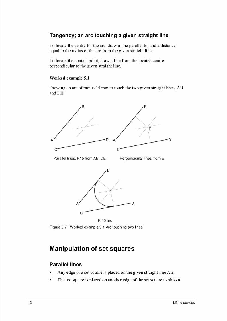
7/31/2019 3 Lifting Devices
http://slidepdf.com/reader/full/3-lifting-devices 233/281

7/31/2019 3 Lifting Devices
http://slidepdf.com/reader/full/3-lifting-devices 234/281

7/31/2019 3 Lifting Devices
http://slidepdf.com/reader/full/3-lifting-devices 235/281
14 Lifting devices
R 2 5
B D
C
A
B D
C
A
Parallel line, 25mm from BD R 25 arc from A Perpendicular from C R 25 arc
Figure 5.10 Worked example 5.2 – arc touching a point and a straight line
Circles in contact, external circle
To construct an arc or circle to touch a given circle, the same basicmethod applies; locate the centre, locate the contact point then draw the
arc or circle.
To locate the centre for the arc, a concentric circle having a radius equal
to the sum of the radii of the two touching circles is drawn from the
centre of the given circle. Concentric circles have the same centre.
If the arc is to touch the given circle and:
i a given point; the centre is located a distance equal to the radius of
the arc from the given pointii a given straight line; the centre is located on a parallel line, a
distance equal to the radius of the arc from the given line
iii another given circle; the centre is located on a concentric circle
having a radius equal to the sum of the radii of the arc and the
second circle.
Having located the centre in each case, the contact point of the touching
circles is located. The contact point of two touching circles is on the line
of centres of the two circles. Therefore, a line is drawn from the centre
of the given circle to the located centre.
Now the point of contact is located for:
i the point
ii the straight line
iii the other circle, using the appropriate method.
The required arc or circle is now drawn.
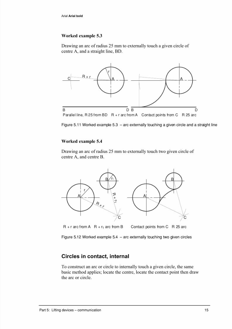
7/31/2019 3 Lifting Devices
http://slidepdf.com/reader/full/3-lifting-devices 236/281

7/31/2019 3 Lifting Devices
http://slidepdf.com/reader/full/3-lifting-devices 237/281
16 Lifting devices
To locate the centre for the arc, a concentric circle having a radius equal
to the difference of the radii of the two touching circles is drawn from the
centre of the given circle.
If the arc is to touch the given circle and:i a given point, the centre is located a distance equal to the radius of
the arc from the given point
ii a given straight line, the centre is located on a parallel line a distance
equal to the radius of the arc from the given line
iii another given circle, externally, the centre is located on a concentric
circle having a radius equal to the sum of the radii of the arc and the
second circle
iv another given circle, internally, the centre is located on a concentric
circle having a radius equal to the difference of the radii of the arcand the second circle.
Now having located the centre in each case, the contact point of the
touching circles is located. The contact point of two touching circles is
again on the line of centres of the two circles. Therefore, a line from the
centre of the given circle to the located centre is drawn.
Now locate the points of contact for each exercise and draw the arc.
Worked example 5.4
Drawing an arc of radius 55 mm to internally touch two given circle of
centre A, and centre B.
A
B
R – r arc from A R – r1 arc from B Contact points from C R 55 arc
A
B
C
R –
r
R – r 1
r
r1
Figure 5.13 Worked example 5.4 – arc internally touching two given circles

7/31/2019 3 Lifting Devices
http://slidepdf.com/reader/full/3-lifting-devices 238/281

7/31/2019 3 Lifting Devices
http://slidepdf.com/reader/full/3-lifting-devices 239/281
18 Lifting devices
with an arc of radius 14 + 50, from the R14 centre. Join this point to
the R14 centre to locate the contact point and draw the R50 arc.
vi Now mark out the size of the shaft, diameter 22 mm, height 35 mm,
and draw the peened head.
vii The ‘upset’ collar can now be completed, the R3 rounds finished and
the R3 curve drawn to complete the shape of the hook.
viii Complete the thick dark outline of the drawing.
Turn to the exercise sheets and complete exercise 5.4, using drawing
instruments.
Preparing for Exercise 5.5
You should now turn to, and attempt Exercise 5.5. The given drawingshows a front view and sectioned right side view of a supporting screw
assembly, drawn to a scale of 1:1. The components have been itemized
and a materials list included.
Turn to the exercise sheets and complete exercise 5.5 answering the
multiple choice questions with reference to the given drawing.

7/31/2019 3 Lifting Devices
http://slidepdf.com/reader/full/3-lifting-devices 240/281
Arial Arial bold
Part 5: Lifting devices – communication 19
Exercises
Exercises 5.1 to 5.3 require you to represent each object using freehand
orthogonal sketching. AS 1100 standards for representing features must
be applied. Accuracy to within 1 mm would be expected.
Exercise 5.4 is an instrument drawing exercise. Use all technical drawingequipment as required.
Exercise 5.5 requires features on a drawing to be identified and the
correct option (a to d) to be selected.

7/31/2019 3 Lifting Devices
http://slidepdf.com/reader/full/3-lifting-devices 241/281
20 Lifting devices

7/31/2019 3 Lifting Devices
http://slidepdf.com/reader/full/3-lifting-devices 242/281
Arial Arial boldhelvetica
S C R E W J
A C K H E A D S
C A L E 1 : 1
E X 5 . 1
A 4
S h a p e a n d s i z e d e t a i l s o f a s c r e w j a c k h e a d a r e
g i v e n b e l o w i n a p i c t o r i a l
d r a w i n g . D r a
w u s i n g a s c a l e o f 1 : 1 , a d e t a i l d
r a w i n g o f t h e s c r e w j a c k
h e a d .
T h e d e t a i l d r a w i n g m u s t i n c l u d e :
( i ) a t o p v i e w i n c o r p o r a t i n g t h e c o n v e n t i o n a l r e
p r e s e n t a t i o n f o r r e p e a t i n g
f i g u r e s
,
( i i ) a h a l f - s e c t i o n e d f r o n t v i e w ,
( i i i ) f u l l d i m
e n s i o n i n g i n c l u d i n g t h e u s e o f s y m b o l s w h e r e a p p r o p r i a t e .
P a r t 5 : L i f t i n g d e v i c e s – c o m m u n i c a t i o n
2 1

7/31/2019 3 Lifting Devices
http://slidepdf.com/reader/full/3-lifting-devices 243/281
Arial Arial boldhelvetica
E X 5 . 2
A 4
Q T Y
M A T L
2 3
L I F T I N G S C R E W A
S S E M B L Y
S
C A L E
:
D r a w i n o r t h o
g o n a l p r o j e c t i o n , u s i n g a s c a l e o
f 1 : 1 , a f r o n t v i e w o f t h e
a s s e m b l e d c o
m p o n e n t s , s h o w i n g :
( i )
a f u l l - s e c t i o n o f t h e h e a d ,
( i i )
a p a r t - s e c t i o n o f t h e l i f t i n g s c r e w t o s h o
w d e t a i l s o f t h e M 1 5 x 1
M S s c r e w ,
( i i i )
i t e m i s e t h e c o m p o n e n t s a n d c o m p l e t e t h e m a t e r i a l s l i s t .
I T E M
N A M E O R D E S C R I P T I O N
P a r t 5 : L i f t i n g d e v i c e s – c o m m u n i c a t i o n

7/31/2019 3 Lifting Devices
http://slidepdf.com/reader/full/3-lifting-devices 244/281
Arial Arial boldhelvetica
P U L L E Y B L O C K A S S E M B L Y
S C A L E
1 : 1
E X 5 . 3
A 4
S h a p e a n d
s i z e d e t a i l s o f c o m p o n e n t s f r o m
a c r a n e h o o k p u l l e y
b l o c k a s s e m b
l y a r e g i v e n b e l o w i n a p i c t o r i a l d r a w
i n g . W i t h t h e c o m p o n e n t s
a s s e m b l e d ,
d r a w , i n o r t h o g o n a l p r o j e c t i o n ,
u s i n g a s c a l e o f 1 : 1 , a
f u l l - s e c t i o n e d
f r o n t v i e w o f t h e p u l l e y b l o c k a s s
e m b l y .
P a r t 5 : L i f t i n g d e v i c e s – c o m m u n i c a t i o n
2 5

7/31/2019 3 Lifting Devices
http://slidepdf.com/reader/full/3-lifting-devices 245/281
Arial Arial boldhelvetica
C R A N E H O O K
S C
A L E
1 : 1
E X 5 . 4
A 4
I n s t r u m e n t d r
a w i n g
S h a p e a n d s i z
e d e t a i l s o f a c r a n e h o o k a r e g i v e n
b e l o w i n a d e t a i l d r a w i n g
a n d a p i c t o r i a
l d r a w i n g . D r a w , i n o r t h o g o n a l p r o
j e c t i o n , u s i n g a s c a l e o f
1 : 1 , a f r o n t v i e w o f t h e c r a n e h o o k , w i t h t h e t o p
p e e n e d o v e r a s s h o w n
i n t h e d e t a i l d r a w i n g . S h o w f u l l c o n s t r u c t i o n f o r c e
n t r e s a n d c o n t a c t p o i n t s .
P a r t 5 : L i f t i n g d e v i c e s – c o m m u n i c a t i o n
2 7
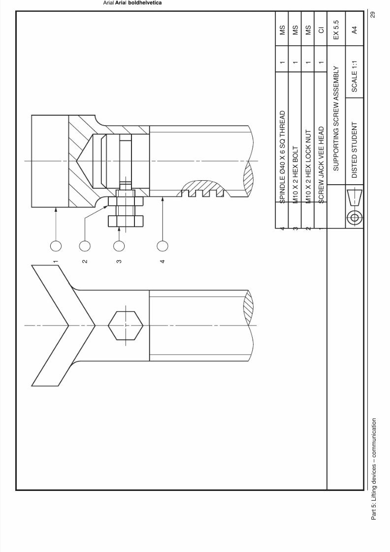
7/31/2019 3 Lifting Devices
http://slidepdf.com/reader/full/3-lifting-devices 246/281
Arial Arial boldhelvetica
S U P P O R T I N G S C R E W A
S S E M B L Y
D I S T E D S T U D E N T
S C A L E 1 : 1
E X 5 . 5
A 4
1
S C R
E W J
A C K V E E H E A D
1
C I
2
M 1 0
X 2 H E X L O C K N U T
1
M S
3
M 1 0
X 2 H E X B O L T
1
M S
4
S P I N D L E Ø 4 0 X 6 S Q T H R E A D
1
M S
4 3 2 1
P a r t 5 : L i f t i n g d
e v i c e s – c o m m u n i c a t i o n
2 9

7/31/2019 3 Lifting Devices
http://slidepdf.com/reader/full/3-lifting-devices 247/281

7/31/2019 3 Lifting Devices
http://slidepdf.com/reader/full/3-lifting-devices 248/281

7/31/2019 3 Lifting Devices
http://slidepdf.com/reader/full/3-lifting-devices 249/281
Arial Arial bold
Part 5: Lifting devices – communication 33
Progress check
During this part you practised freehand sketching and CAD/instrument
drawing using the AS 1100 standards and were introduced to some new
techniques including the standard representation of repeated features and
parts.
Take a few moments to reflect on your learning then tick the box that best
represents your level of achievement.
❏✓ Agree – well done
❏✓ Disagree – revise your work
❏✓ Uncertain – contact your teacher A g r e e
D i s a g r e e
U n c e r t a i n
I have learnt about:
• communication
– Australian Standard AS 1100
– sectioning of orthogonal views
– orthogonal assembly drawings.
I have learnt to:
• produce orthogonal drawings applying appropriate
– australian standard (AS 1100) –computer graphics/computer assisted drawings.
• apply dimensions to AS 1100.
Extract from Stage 6 Engineering Studies Syllabus, © Board of Studies, NSW, 1999.
Refer to <http://www.boardofstudies.nsw.edu.au> for original and current documents.
During the next part you will investigate some lifting devices in order to
write your engineering report.

7/31/2019 3 Lifting Devices
http://slidepdf.com/reader/full/3-lifting-devices 250/281

7/31/2019 3 Lifting Devices
http://slidepdf.com/reader/full/3-lifting-devices 251/281
Arial Arial bold
Part 5: Lifting devices – communication 35
Exercise cover sheet
Exercises 5.1 to 5.5 Name: _______________________________
Check!
Have you have completed the following exercises?
❐ Exercise 5.1
❐ Exercise 5.2
❐ Exercise 5.3
❐ Exercise 5.4
❐ Exercise 5.5
Locate and complete any outstanding exercises then attach your responses to this sheet.
If you study Stage 6 Engineering Studies through a Distance Education
School/Centre (DEC) you will need to return the exercise sheet and your
responses as you complete each part of the module.
If you study Stage 6 Engineering Studies through the OTEN Open
Learning Program (OLP) refer to the Learner’s Guide to determine which
exercises you need to return to your teacher along with the Mark Record
Slip.
7/31/2019 3 Lifting Devices
http://slidepdf.com/reader/full/3-lifting-devices 252/281
Lifting devices
Part 6: Lifting devices –engineering report

7/31/2019 3 Lifting Devices
http://slidepdf.com/reader/full/3-lifting-devices 253/281
Part 6: Lifting devices – engineering report 1
Part 6 contents
Introduction..........................................................................................2
What will you learn?...................................................................2
Engineering reports............................................................................3
Sample engineering report................................................................9
Exercise .............................................................................................19
Progress check .................................................................................21
Exercise cover sheet........................................................................23
Bibliography.......................................................................................25
Module evaluation ............................................................................27

7/31/2019 3 Lifting Devices
http://slidepdf.com/reader/full/3-lifting-devices 254/281

7/31/2019 3 Lifting Devices
http://slidepdf.com/reader/full/3-lifting-devices 255/281
Part 6: Lifting devices – engineering report 3
Engineering reports
Engineering requires compromise. There are always conflicting criteria
and specifications. The design engineer must evaluate and select. Any
design can only be judged as the best solution based on the set criteria. If
the criteria change, so might the best solution change.
What is the best car?
The best car might be:
• the most fuel efficient
• the easiest to manufacture
• the most recyclable
• the fastest
• the one with the most powerful motor
• the best colour
• the most reliable
• the safest
• the most versatile
• the car with the most accessories.
The answer to this question depends entirely on what criteria you select
to base the evaluation.
The list seems endless. If you select more than one criteria to base your
evaluation, the best might be decided on what weight you give to the
criteria. Recyclability might be given a weighting twice that of best
colour.
It is important to remember that an engineering report will be based on
the authors analysis of the collected data, not on a personal opinion. For
instance, to find the best colour, the author would need to carry out
research and collect data, such as sales figures over the past year and a
public survey. The author would report on the data collected, not on
their favourite colour!

7/31/2019 3 Lifting Devices
http://slidepdf.com/reader/full/3-lifting-devices 256/281
4 Lifting devices
Researching an engineering report
You will need to demonstrate in your report that you have used many
types of sources to research information for your report. Include Internet
sites as well as CD ROM journals, phone interviews or industry visitswhere possible, books and the encyclopaedia.
All the references should be listed at the back of the report under the
heading references. Source information should be cited on the relevant
pages in the report where you have used the source.
The engineering report sections
The engineering report should be written under the following headings:• title
• abstract
• introduction
• analysis
• result summary
• conclusions
• acknowledgments
• bibliography
• appendices.
Title page
The title page gives the title of the report, identifies its writer or writers
and the date when the report was completed. You might add a drawing
of the object on the title page.
Abstract
The abstract is a very concise summary of the report. The purpose of the
abstract is to allow a reader to decide if the report contains information
about which they are researching.
The abstract should be no more than two or three paragraphs of text, and
shorter if possible. It should cover the scope of the report (what it is
about), and the approach or approaches used to complete the analysis
(how the information was assembled).

7/31/2019 3 Lifting Devices
http://slidepdf.com/reader/full/3-lifting-devices 257/281

7/31/2019 3 Lifting Devices
http://slidepdf.com/reader/full/3-lifting-devices 258/281
6 Lifting devices
Result summary
This section presents the results concisely (the details can be set out in an
appendix). The results will be used as the basis for your conclusions and
recommendations.
This section should also note any limitations on the results obtained. For
example, if you conduct an experiment to find out the average
temperature in your home, you might measure the temperature every
hour for three days in succession, and then calculate the average. In the
results section, when stating the average temperature for your home, you
should also point out that the figure might be different at other times of
the year due to seasonal variations.
Conclusions
This section requires the writer to draw conclusions based on data
collected. If the purpose of the report was to ‘select the best…..’, then the
selection is now stated and the reason for the selection is explained.
Remember the ‘best’ jack will be determined based on the criteria you
have set to evaluate each jack.
Acknowledgments
The acknowledgment section provides the opportunity to acknowledge,
or thank, other people who have contributed to the completion of thereport. For example, a local mechanic may have demonstrated their
hydraulic jack. While the mechanic may not have helped you directly
with the calculations, without their contribution the investigation would
not have been possible. Hence an acknowledgement would be
appropriate.
Bibliography
This section is most critical for two reasons. Firstly you must
demonstrate that the report is well researched. This can be demonstrated
by including references to the most important sources of informationrelevant to the investigation.
Secondly, it is important to acknowledge the various sources of
information you have used.
Sometimes we think it is cheating to use other people's work. This is not
true. If we did not use other peoples work, and did everything ourselves
from scratch, we would never progress very far. Real progress is made by
building on the work of others.

7/31/2019 3 Lifting Devices
http://slidepdf.com/reader/full/3-lifting-devices 259/281
Part 6: Lifting devices – engineering report 7
If you use someone else's work you must reference the fact accordingly.
This is the literal basis for 're-search' : to re-find a result that someone
else discovered. If you use someone else's work without referencing the
fact, you are implicitly claiming it to be your own. This is "cheating", or
as it is more usually called, 'plagiarism'.
The Harvard system is a standard academic method of referencing. A
sample of how to reference this way is given in the following section.
Follow this technique accurately.
Higgins, R.A 1977, Properties of Engineering Materials, Edward
Arnold, Sydney.
Standards for bibliography entries must follow the strict guidelines. All
references must be included.
Appendices
This section contains information that has been separated from the main
body of the report because it is not essential that every reader look at this
information. It is information that enhances the other data. An example
would be engineering drawings of the appliances being compared. The
overall dimensions of the product may not have been part of the report,
but some readers may need this specific information. During the
engineering course this section will always contain a technical drawing
and will often contain pamphlets collected from organisations and
Internet page copies.
As this is the last part of this module you should demonstrate all the
skills you have gained to produce the best possible report.

7/31/2019 3 Lifting Devices
http://slidepdf.com/reader/full/3-lifting-devices 260/281
8 Lifting devices

7/31/2019 3 Lifting Devices
http://slidepdf.com/reader/full/3-lifting-devices 261/281
Lifting devices
Title: Efficiency of lifting jacks
Author/s: Jack Advantage
Date: June 2000
Abstract: This report analyses two different types of lifting jacks, a
caliper screw jack and a hydraulic jack, and compares
their relative efficiency.
Introduction
Car jacks are used to raise the wheels of a vehicle off the ground.
This report analyses two different types of car jack by comparing their
efficiency to lift the front section of a medium sized utility. The
research involved estimating the mechanical advantage and velocity
ratio of both jacks and then using this data to estimate the efficiency
of each device as a percentage. This allowed an objective assessment
to be made regarding the most efficient device.
The jacks analysed are a caliper screw jack and a hydraulic jack.
Details of both of these are shown in the Appendices.
Analysis
The calculations for this report are based on estimating the load lifted
by the jacks and then establishing the Velocity Ratio and Mechanical
Advantage of the two jacks when lifting this load. Once this has been
calculated, the formula for efficiency can be used to make acomparison between the two jacks:
Efficiency = Mechanical Advantage
Velocity Ratio
The load lifted by the jacks is an estimation based on the mass given
under the bonnet of the car on the compliance plate. This is shown as
2350 kg on the vehicle used in this research which was a Toyota Hilux
four wheel drive. The load lifted by the jacks has to be estimated
because the centre of gravity of the utility will be towards the front of the vehicle due to the effect of the motor which is nearer to the front.

7/31/2019 3 Lifting Devices
http://slidepdf.com/reader/full/3-lifting-devices 262/281
As shown below in Figure 6.1 the centre of gravity of the vehicle is
estimated to be 1metre from the centre of the front wheels.
1
2.8
c of g
Figure 6.1 The vehicle and the estimated position of the centre of
gravity
Once the centre of gravity is estimated, a sum of the moments can be
taken about the rear wheels to establish the load lifted by the jacks.
The Mechanical Advantage and the Velocity Ratio can be determined
using the following formulae:
Mechanical Advantage = Load(Newtons) / Effort (Newtons)
Velocity Ratio = Distance moved by Effort / Distance
moved by Load
The approach taken to compare a caliper screw jack to a hydraulic
jack can be summarised as follows:
• establish a common load to be lifted by the jacks
• lift the load by the same distance for both jacks
• establish the mechanical advantage and velocity ratio for both
jacks under the same conditions
• calculate the efficiency of the two jacks.

7/31/2019 3 Lifting Devices
http://slidepdf.com/reader/full/3-lifting-devices 263/281
Caliper screw jack
The caliper screw jack, shown below in figure 6.2, is based on the
principle of a screw thread. As the handle of the jack is turned the
threaded shaft in the centre rotates to bring together the two arms of the jack causing the top to rise and therefore the load to lift. The
turning crank used on the caliper jack is shown in figure 6.3, it has an
offset handle as shown of 140 millimetres giving a turning diameter of
280 millimetres. This adds a lever advantage to this jack. An
orthogonal drawing showing the Front View of a caliper screw jack is
given in the Appendix, figure 6.10.
Figure 6.2 Caliper screw jack
1 4 0 m m
Figure 6.3 The turning crank for the caliper screw jack showing the
turning radius of 140 mm
2.5 mm pitch
Figure 6.4 Details of the square thread on the caliper jack showing a pitch of2.5mm

7/31/2019 3 Lifting Devices
http://slidepdf.com/reader/full/3-lifting-devices 264/281
The hydraulic jack shown below in figure 6.5 is based on the principle
that fluid is incompressible. As the lever is depressed the piston on
the right hand side forces hydraulic fluid through a valve to lift the
ram which causes the load to lift. A sketch showing the operation of a
hydraulic jack is given in figure 6.6.
Figure 6.5 Hydraulic jack
Ram (load)Piston (effort)
Figure 6.6 Schematic diagram of a hydraulic jack
The effort required to lift the load supported by each jack was
calculated by using spring balances, calibrated in N. A picture of
these spring balances in use is shown in figure 6.2 and figure 6.5. The
maximum force measured by the spring balances was 50 N, this
required two spring balances to be arranged in parallel. A reading of
90 N (2 x 45 N) was obtained.

7/31/2019 3 Lifting Devices
http://slidepdf.com/reader/full/3-lifting-devices 265/281
Calculations
Establishing the load lifted by the jacks:
Data
Distance between the axles = 2.8 metres
Mass of the utility = 2350 kgs
If it is assumed that the centre of gravity of the utility is 1 metre from
the front axle, due to the fact that the motor is towards the front, theload lifted by the jacks can be calculated by taking moments about the
rear axle as follows:
23500 N
15107 N 8393 N
1 m
Figure 6.7 Freebody diagram of load lifted by jacks
Weight = m ¥ g
= 2350 ¥ 10
= 23500 N
∑MR = F ¥ d + F ¥ d
= - (23500 x 1.8) + (R F x 2.8)
R F = 15107 N
From the calculations above it is estimated that a load of 15 107
Newtons will be lifted by each jack when it is placed in the position
shown below in figure 6.8.

7/31/2019 3 Lifting Devices
http://slidepdf.com/reader/full/3-lifting-devices 266/281
Figure 6.8 A jack in position lifting the load calculated above
From figure 6.3 it can be seen that the radius of the handle used on the
caliper screw jack is 140 mm. The diameter is thus 280 mm. This
means that the distance moved by the effort is D or the
circumference of the circle the effort will travel in as the jack is
raised. When the thread on the jack is rotated one revolution the
caliper jack shown in figure 6.2 rises 2.5 mm, this is the distance or
lead the thread moves through one revolution of the handle, which is
also equal to the pitch of the thread.
Using the information given above the Velocity Ratio and Mechanical
Advantage and efficiency of a caliper screw jack can be calculated as
follows:
Velocity Ratio = Distance moved by Effort/Distance moved by Load
= D / 2.5 (millimetres)
= x 280 / 2.5
Mechanical Advantage = 351.8
= Load / Effort
= 167.8
Efficiency = Mechanical advantage / Velocity ratio
= 168 / 352
= 47.7 %

7/31/2019 3 Lifting Devices
http://slidepdf.com/reader/full/3-lifting-devices 267/281
Hydraulic jack
The Velocity Ratio of the hydraulic jack needs to be calculated in a
different way to the caliper screw jack as it works on a different
principle. The basic features of the hydraulic jack can be seen infigure 6.6. As the piston on the hydraulic jack is depressed the ram
will move upwards so that the volume of the piston (effort) which is
pushed into the oil must equal the volume of the ram (load) that is
displaced by the oil as it moves upwards, therefore (d2/4)h =
(D2/4)H. Where d= the diameter of the piston, h = distance moved
by the piston and D = the diameter of the ram, H = the distance moved
by the ram.
Therefore:
Velocity ratio = Distance moved by Effort/Distance moved by Load
h / H = (D2/4) / (d
2/4)
= D2/d
2
For the hydraulic jack therefore:
Velocity Ratio = D2
of the ram / d2
of the piston
= 502/ 10
2
= 2500 / 100
= 25
Applied force50 N
Reaction force
560 mm
Apivot
40 mm
Figure 6.9 Freebody diagram of lever forces in the hydraulic jack handle

7/31/2019 3 Lifting Devices
http://slidepdf.com/reader/full/3-lifting-devices 268/281
The force applied to the lever of the jack was found to be 50 Newtons.
The Mechanical Advantage gained by the hydraulic jack occurs in two
stages. Firstly the lever has a mechanical advantage that is applied to
the piston and secondly the hydraulic system creates an M.A. betweenthe piston and the ram of the jack. The effort that is applied by the
lever to the piston can be calculated by taking moments about point A
in figure 6.9, as follows
∑MA = (F ¥ d) + (F ¥ d)
= (F ¥ 0.04) – (50 ¥ 0.56)
F = 28 / 0.04
= 700 N
Mechanical Advantage = Load / Effort
= 15107 / 700
= 21.58
Efficiency = Mechanical Advantage / Velocity Ratio
= 21.58 / 25 ¥ 100
= 86%
Result summary
From the calculations above it can be seen that the caliper screw jack
has an estimated efficiency of 48% whereas for the hydraulic jack it is
86%.
Conclusions
This report on the efficiency of a caliper screw jack as compared to a
hydraulic jack indicates that the hydraulic jack is clearly the most
efficient by a margin of 38%. Therefore, in any situation where
efficiency is required a hydraulic jack should be used.
There are some disadvantages however in that a hydraulic jack ismore expensive than a caliper screw jack and usually heavier due to
the more robust construction and the hydraulic fluid used to operate it.

7/31/2019 3 Lifting Devices
http://slidepdf.com/reader/full/3-lifting-devices 269/281
Also, the caliper screw jack can be compressed into a smaller space
when it is wound in compared to the hydraulic jack allowing it to take
up a relatively smaller space.
In conclusion then, whilst the hydraulic jack is more efficient there are
other factors which may make the caliper jack more suitable in
situations where a lighter load needs to be lifted and space is critical.
The caliper screw jack may be the better choice for example, as an
accessory for a car where it is mainly used when changing tyres.
Glossary
centre of gravity a term used to describe the point
that is the centre for the mass of an object
compliance plate metal plate under the bonnet
indicating details such as the mass
of a vehicle
hydraulic Operated by or employing water
or other fluid
ram the piston that lifts on a hydraulic
jack
Bibliography
Holden, R. 1991, A Guide to Engineering Mechanics,
Science Press, Sydney.
Schlenker, B. McKern, D. 1976, Introduction to Engineering Mechanics,
John Wiley & Sons, Sydney.
<www.motojacks.com/>
<www.bobstools.com/prd0129.htm>
<www.sktoolstore.com/astro/500fc.html>
<www.autoramps.com>
<www.ralmikes.com.catalog/temp_top_right.cfm?Familyid=mv46sj2000>
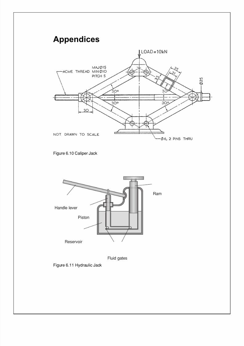
7/31/2019 3 Lifting Devices
http://slidepdf.com/reader/full/3-lifting-devices 270/281
Appendices
Figure 6.10 Caliper Jack
Handle lever
Ram
Piston
Fluid gates
Reservoir
Figure 6.11 Hydraulic Jack

7/31/2019 3 Lifting Devices
http://slidepdf.com/reader/full/3-lifting-devices 271/281
Part 6: Lifting devices – engineering report 19
Exercise
You have read the sample engineering report comparing the efficiency of
two different types of lifting devices. It is now time to begin your
engineering report.
In the sample report, efficiency was the only criteria on which the jacks
were compared. There are numerous qualities that could be used for a
comparison. For instance, you could compare two jacks to find the best
jack for off road conditions. You might therefore include in your criteria
evaluation:
• the initial cost
• the weight
• the reliability
• the maximum height of the lift
• maintenance requirements.
The more criteria you add to your evaluation, the more complex the
analysis becomes. In addition, not all criteria are likely to be of the same
importance. The criteria are therefore weighted on their importance.
The height of the possible lift might be twice as important as
maintenance. A table of the criteria should be created and a score
recorded for each jack in each criteria. The weighting for the criteria is
then calculated. The score for each jack in each criteria is then totalled,
determining the best jack. In the conclusion the author should note how
the criteria and the weighting of criteria would influence the result.
Exercise 6.1
Write an engineering report that compares two lifting devices. The lifting
devices should perform a similar task but use different techniques to
achieve the result. You should compare the devices based on three criteria
that you determine are the most important characteristics/requirements of
the devices. Use a weighting system for the criteria. The results should
show clear evidence of the research completed by the author. Data might
be collected, depending on the criteria, using calculations, surveys,
experimentation and text information.

7/31/2019 3 Lifting Devices
http://slidepdf.com/reader/full/3-lifting-devices 272/281

7/31/2019 3 Lifting Devices
http://slidepdf.com/reader/full/3-lifting-devices 273/281
Part 6: Lifting devices – engineering report 21
Progress check
During this part you have examined the structure and format of a typical
engineering report.
Take a few moments to reflect on your learning then tick the box that best
represents your level of achievement.
❏✓ Agree – well done
❏✓ Disagree – revise your work
❏✓ Uncertain – contact your teacher A g r e e
D i s a g r e e
U n c e r t a i n
I have learnt about
• engineering report writing.
I have learnt to
• research information
• complete an engineering report based on the analysisand synthesis of information using software andcomputer assisted drawing where appropriate.
Extract from Stage 6 Engineering Studies Syllabus, © Board of Studies, NSW, 1999.
Refer to <http://www.boardofstudies.nsw.edu.au> for original and current documents.
Congratulations! You have completed the module on Lifting devices.

7/31/2019 3 Lifting Devices
http://slidepdf.com/reader/full/3-lifting-devices 274/281
22 Part 6: Engineering report for lifting devices

7/31/2019 3 Lifting Devices
http://slidepdf.com/reader/full/3-lifting-devices 275/281

7/31/2019 3 Lifting Devices
http://slidepdf.com/reader/full/3-lifting-devices 276/281
24 Part 6: Engineering report for lifting devices

7/31/2019 3 Lifting Devices
http://slidepdf.com/reader/full/3-lifting-devices 277/281
25
Bibliography
Avner, S.A. 1974, Introduction to Physical Metallurgy , McGraw-Hill,Singapore.
BHP Steel, http://www.ezysteel.com
Board of Studies, 1999, Stage 6 Engineering Stuidies Examination, Assessment
and Reporting , Board of Studies NSW, Sydney.Board of Studies, 1999, Stage 6 Engineering Stuidies Support Document ,
Board of Studies NSW, Sydney.
Board of Studies, 1999, Stage 6 Engineering Stuidies Syllabus ,Board of Studies NSW, Sydney.
Eide, Jenison, Marshaw & Northup, 1998, Introduction to Engineering Design n,McGaw Hill, United States.
Crane (machine), http://encarta.msn.com, Encarta Encyclopeadia Article Titled‘Crane (machine)’
Davis, Troxell, Wiskocil 1964, The Testing and Inspection of Engineering Materials , McGraw-Hill, Tokyo.
DeGarmo, E.P. 1966, Materials and Processes in Manufacturing , Macmillan,New York.
Die Casting in Australia, http://www.diecasting.asn.au/about.html
Drop Forging, http://bdl-mc.qc.ca/processes/mprg/drop_forging.html
General Floor Jacks, http://www.hyjacks.com
Guy, A.G. 1972, Introduction to Materials Science , McGraw-Hill,
Tokyo.Harding, D.W, and Griffiths, L 1970, Materials, Longman,
London.
Hiab Cranes, http://www.redaustralia.com
Higgins, R.A 1987, Materials for the Engineering Technician , Edward Arnold,London.
John, V.B. 1985, Introduction to Engineering Materials , MacMillan,London.
Manufacturing, http://www.wichard-usa.com/manufacture.html

7/31/2019 3 Lifting Devices
http://slidepdf.com/reader/full/3-lifting-devices 278/281
26
National Centre for Excellence in Metalworking Technology, Material Standardsfor Powder Metallurgy Alloys, http://www.ncemt.ctc.com
Otis Elevator Company, http://www.otis.com.html
Otis Elevator Company, Student Information, Otis Pty Ltd,Minto, NSW.
Rochford, J. 1999, Engineering Studies – A Student’s Workbook , K.J.S.Publications, Gosford.
Schlenker, B.R. 1974, Introduction to Materials Science, Wiley, Sydney.
Teaching Resources, 1981, Cranes, lift, loft and slew, Division of Services NSWDepartment of Education
The Correspondence School, 1993, Engineering Science – 2 Unit Cours e,Learning Materials Production Centre, Redfern
Van Vlack, L.H. 1973, A Textbook of Materials Technology , Addison-Wesley,Massachusetts.
Hibbler, R C. 1989, Engineering Mechanics – Statics , Macmillan,Sydney.
Holden, R. 1991, A Guide to Engineering Mechanics , Science Press,Sydney.
Mullins, R K. 1983, Engineering Mechanics , Longman Cheshire, UnitedKingdom.
Rochford, J. 2000, Engineering Studies – Student’s Handbook , KJSPublications, Gosford.
Schlenker, B. McKern, D. 1976, Introduction to Engineering Mechanics , JohnWiley & Sons, Sydney.
Schlenker, B. McKern, D. 1983, Introduction to Engineering Mechanics ,Jacaranda Press, Sydney.
Taylor, A. Barry, O. 1975, Fundamentals of Engineering Mechanics , Cheshire,
Wolf, L. 1990, Statistics and Strength of Materials: a parallel approach to understanding structures , Merrill, New York.
Otis Elevator Company, Otis student package.
http://www.ph.unimelb.edu.au/lecdem/fa1.htm
www.howstuffworks.com (enter ‘hydraulic crane’ into search box)
http://www.sasked.gov.sk.ca/docs/physics/u6c3phy.html
www.motojacks.com
www.bobstools.com/prd0129.htm
www.sktoolstore.com/astro/500fc.html
www.autoramps.com
www.ralmikes.com.catalog/temp_top_right.cfm?Familyid=mv46sj2000

7/31/2019 3 Lifting Devices
http://slidepdf.com/reader/full/3-lifting-devices 279/281
27
Module evaluation
To help us make improvements to future learning materials we would
like your comments on this material.
Tick the box which best describes you.
Gender male female
Study through DEC OTEN - OLP Other
Age group under 20 years 20–30 years over 30
Circle the number that best represents your rating of this material.
The number 1 indicates a low rating and the number 5 indicates a high
rating.
There is room to make comment if you would like.
1 Rate your enjoyment of the
material.
1 2 3 4 5
___________________________
___________________________
___________________________
2 Rate your understanding of the
content.
1 2 3 4 5
___________________________
___________________________
___________________________
3 Rate the usefulness of the
activities.
1 2 3 4 5
___________________________
___________________________
___________________________

7/31/2019 3 Lifting Devices
http://slidepdf.com/reader/full/3-lifting-devices 280/281
28
4 Rate the relevance of the
exercises.
1 2 3 4 5
____________________________
____________________________
____________________________
5 Rate the accuracy of the
indicative time given.
1 2 3 4 5
____________________________
____________________________
____________________________
6 Rate the ease of obtaining the
resources.
1 2 3 4 5
____________________________
____________________________
____________________________
7 Rate the helpfulness of any
support material.
1 2 3 4 5
____________________________
____________________________
____________________________
8 Rate your achievement of the
outcomes for the material.
1 2 3 4 5
____________________________
____________________________
____________________________
Finally!
Which were the most challenging parts of the material?
__________________________________________________________
__________________________________________________________
Please return this form to your teacher to forward on to OTEN – LMP.
Thank you for this valuable information.

7/31/2019 3 Lifting Devices
http://slidepdf.com/reader/full/3-lifting-devices 281/281