3. keys and couplingsmitpolytechnic.ac.in/.../dme/unit03.2keysandcouplings.pdf · 2018-04-20 ·...
TRANSCRIPT

3. Keys and Couplings Keys –
A key is a piece of mild steel inserted between the
shaft and hub or boss of the pulley to connect these together in order to prevent relative motion between them.
It is always inserted parallel to the axis of the shaft. Keys are used as temporary fastenings and are subjected to considerable crushing and shearing stresses.
A keyway is a slot or recess in a shaft and hub of the pulley to accommodate a key.

Types of Keys
• The following types of keys are important
from the subject point of view :
1. Sunk keys,
2. Saddle keys,
3. Tangent keys,
4. Round keys,
5. Splines.

Sunk Keys
• The sunk keys are provided half in the keyway of the shaft and half in the keyway of the hub or boss of the pulley. The sunk keys are of the following types :
1. Rectangular sunk key. A rectangular sunk key is shown in Fig.
The usual proportions
• Width of key, w = d / 4 ;
• thickness of key, t = 2w / 3 = d / 6
• where d = Diameter of the shaft or diameter of the hole in the hub.
• The key has taper 1 in 100 on the top side only.

2. Square sunk key.
• The only difference between a rectangular sunk key and a square sunk key is that its width and thickness are equal, i.e.
• w = t = d / 4
3. Parallel sunk key.
• The parallel sunk keys may be of rectangular or square section uniform in width and thickness throughout. It may be noted that a parallel key is a taperless and is used where the pulley, gear or other mating piece is required to slide along the shaft.

4. Gib-head key.
It is a rectangular sunk key with a head at one end
known as gib head. It is usually provided to
facilitate the removal of key.
The usual proportions of
the gib head key are :
Width, w = d / 4 ;
and thickness at large end,
t = 2w / 3 = d / 6

Effect of Keyways
• A little consideration will show that the keyway cut into the shaft reduces the load carrying capacity of the shaft.
• This is due to the stress concentration near the corners of the keyway and reduction in the cross-sectional area of the shaft.
• It other words, the torsional strength of the shaft is reduced.
• The following relation for the weakening effect of the keyway is based on the experimental results by H.F. Moore.

)(7.0)(4.01
Re
)(
,
)(1.1)(2.01
2
)(
d
h
d
wK
twistangularforfactorductionK
thenkeywayslidingandlongtooisshaftIf
keywayofdepthh
shaftofdiameterd
keywayofwidthw
shaftsameforkeywaywithoutshaftofstrength
keywaywithshaftofstrengthe
factorstrengthShaftewhere
d
h
d
we
o
o
tkeywayofthickness
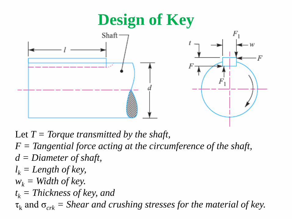
Design of Key
Let T = Torque transmitted by the shaft,
F = Tangential force acting at the circumference of the shaft,
d = Diameter of shaft,
lk = Length of key,
wk = Width of key.
tk = Thickness of key, and
τk and σcrk = Shear and crushing stresses for the material of key.

1) Direct Shear stress in key –
2
2
tanRe
dlwT
dFT
cedisdialForceTTorqueAlso
lwF
lw
F
Area
forceShear
d
d
d

2) Crushing stress in key –
22
2,
2
2
dtlT
dFTTorquealso
tlF
tl
F
A
F
Area
forceeCompressiv
cr
cr
cr
cr

Couplings
• Shafts are available in varying length from 6 to
10 meters for easy handling and transportation.
• Larger length shafts can not be manufactured in
correct for the use of power transmission.
• But in actual practice, larger length shafts are
required for transmission of torque and power.
• This requirement will be fulfilled by the use of
coupling which joined two or more shafts so
coupling is a device used to join two or more
shafts.

Requirements of a Good Shaft Coupling
• A good shaft coupling should have the
following requirements :
1. It should be easy to connect or disconnect.
2. It should transmit the full power from one shaft
to the other shaft without losses.
3. It should hold the shafts in perfect alignment.
4. It should reduce the transmission of shock loads
from one shaft to another shaft.
5. It should have no projecting parts.

Factors Consider in Selection of
Coupling
1) Torque requirement.
2) Speed involved.
3) Shaft misalignment.
4) Operating condition.
5) Cyclic operation.
6) Direction of rotation.
7) Life of coupling.
8) Duty or work involved.

• Why a coupling should be placed as close to a
bearing as possible?
Answer – Coupling should be placed as close to a
bearing because of following reasons
1. It gives minimum vibrations.
2. Bending load on the shaft can be minimized.
3. It increases power transmission stability.
4. To avoid deflections of shaft.

Types of Couplings
1) Rigid coupling –
it is used to connect two shafts which are parallel
and in alignment.
a) Sleeve or muff coupling.
b) Clamp or split muff coupling.
c) Flange coupling.

2) Flexible coupling –
It is used to connect two shafts which are
parallel and not in alignment.
a) Bushed pin type flexible coupling.
b) Universal coupling.
c) Oldham coupling.

Parameters Rigid Coupling Flexible Coupling
Purpose Rigid couplings are used to
connect two shafts which
are perfectly aligned.
Flexible couplings are used
to connect two shafts
having small
misalignment.
Alignment Rigid couplings can not
tolerate any misalignment
between two shafts.
Flexible couplings can
tolerate small amount of
misalignment between two
shafts.
Shock &
Vibration
Rigid couplings can not
absorb shock and vibration.
Flexible couplings can
absorb shock and vibration.
Deflection In rigid couplings, shaft
deflection is less.
In flexible couplings, shaft
deflection is more.
Cost These are less expensive These are more expensive.

1. Muff or Sleeve Coupling
It is the simplest type of rigid coupling, made of cast iron. It consists of a
hollow cylinder whose inner diameter is the same as that of the shaft. It
is fitted over the ends of the two shafts by means of a gib head key, as
shown in Fig. The power is transmitted from one shaft to the other shaft
by means of a key and a sleeve. It is, therefore, necessary that all the
elements must be strong enough to transmit the torque.

Design of Muff or Sleeve Coupling
Advantages – 1. It is simple in construction
2. It has no projection part.


1) Design of Shaft –
The diameter of shaft should be calculated as
discussed in earlier section of shaft.
2) Design of Sleeve –
The sleeve is design by considering a hollow
shaft.
According to standard proportion –
Outside diameter of sleeve = D = 2d + 13
Length of sleeve = L = 3.5d

sleeveinstressshear
thechecktousedisequationThis
D
dkWhere
kDT
sleeveoffailure
sheartorsionalthegConsiderin
)1(16
)3
43

crushingdt
lTii
shearingd
wlTi
crushingandShearing
forcheckedtoiskeythatAfter
dLlkeyoflengthAnd
dtw
keysquareFor
dt
dw
keygularrecFor
keyofDesign
kcrk
k
kkk
k
kk
kk
22)
2)
2
5.3
2
4
6&
4
tan
)4

Split Muff Coupling
• It is also known as split muff coupling.
• In this case, the muff or sleeve is made into two
halves and are bolted together as shown in Fig.
• The halves of the muff are made of cast iron. The
shaft ends are made to about each other and a
single key is fitted directly in the keyways of both
the shafts.
• One-half of the muff is fixed from below and the
other half is placed from above.

• Both the halves are held together by means of
mild steel studs or bolts and nuts.
• The number of bolts may be two, four or six.
• The nuts are recessed into the bodies of the muff
castings.
• This coupling may be used for heavy duty and
moderate speeds.
• The advantage of this coupling is that the position
of the shafts need not be changed for assembling
or disassembling of the couplings.


Design procedure
• T = Torque transmitted by the shaft,
• d = Diameter of shaft,
• db = Root or effective diameter of bolt,
• n = Number of bolts,
• σt = Permissible tensile stress for bolt material,
• μ = Coefficient of friction between the muff and
shaft, and
• L = Length of muff.

1) Design of Shaft –
The diameter of shaft should be calculated as
discussed in earlier section of shaft.
2) Design of Sleeve –
The sleeve is design by considering a hollow
shaft.
According to standard proportion –
Outside diameter of sleeve = D = 2d + 13
Length of sleeve = L = 3.5d

sleeveinstressshear
thechecktousedisequationThis
D
dkWhere
kDT
sleeveoffailure
sheartorsionalthegConsiderin
)1(16
)3
43

crushingdt
lTii
shearingd
wlTi
crushingandShearing
forcheckedtoiskeythatAfter
dLlkeyoflengthAnd
dtw
keysquareFor
dt
dw
keygularrecFor
keyofDesign
kcrk
k
kkk
k
kk
kk
22)
2)
2
5.3
2
4
6&
4
tan
)4

24
4
4
)(
2
2
2
ndf
isshafttheofsideeach
onboltsthebyexertedforceThe
dfbolteachbyexertedForce
d
fforce
loadtensiletosubjectedareboltsThe
tb
tb
b
t

dL
nd
P
areaprojected
forceP
muffshafttheonppressuretoduesurfacethe
overondistributipressureuniformFor
tb
2
124
&''
2

ndF
dL
dL
nd
F
dLPF
areaessureF
muffshafteachbetweenforceFrictional
tb
tb
22
2
8
2
1
2
124
2
1
Pr
&
.
16
28
2
22
22
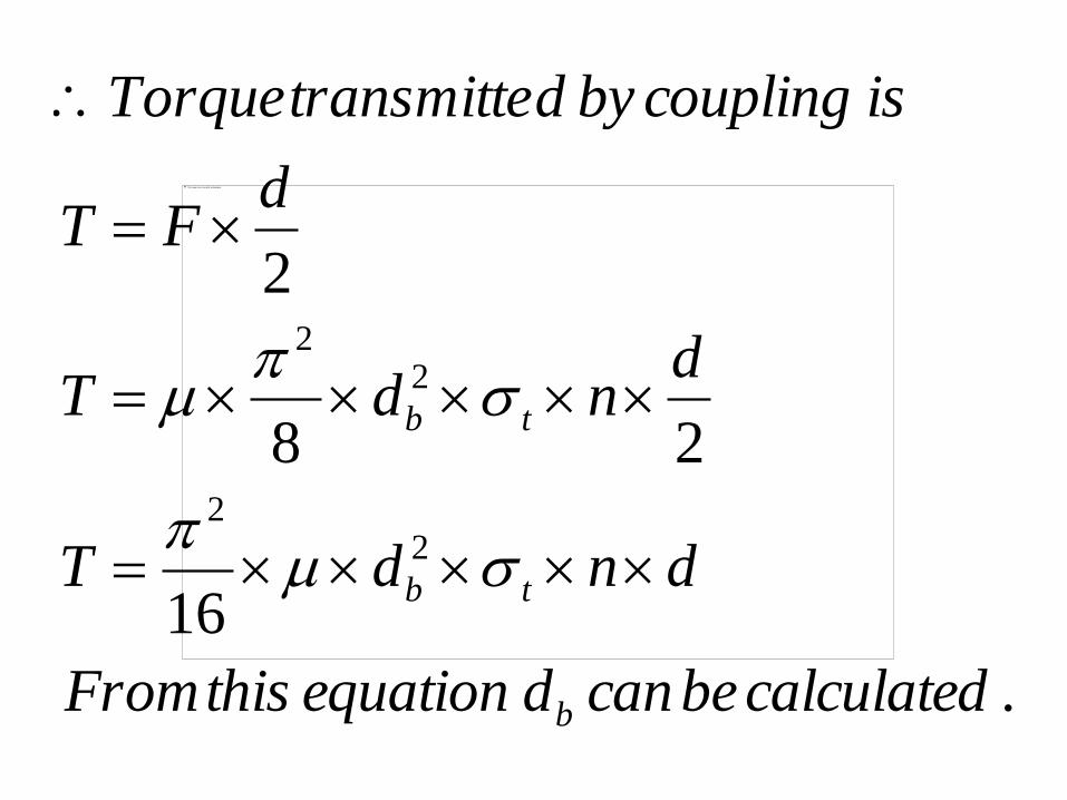
calculatedbecandequationthisFrom
dndT
dndT
dFT
iscouplingbydtransmitteTorque
b
tb
tb

Flange Couplings
• A flange coupling usually applies to a coupling
having two separate cast iron flanges.
• Each flange is mounted on the shaft end and
keyed to it.
• The faces are turned up at right angle to the axis
of the shaft.
• One of the flange has a projected portion and the
other flange has a corresponding recess. This
helps to bring the shafts into line and to maintain
alignment.

• The two flanges are coupled together by means of
bolts and nuts. The flange coupling is adopted to
heavy loads and hence it is used on large shafting.
• The flange couplings are of the following three
types :
1) Unprotected type flange coupling
2) Protected type flange coupling
3) Marine type flange coupling

Protected Type Flange Coupling
• Protected Type Flange Coupling
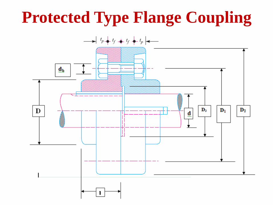
Protected Type Flange Coupling

boltsofnumbern
boltofdiameteralnod
flangeprotectiveofthicknesst
flangeofthicknesst
huboflengthl
recessflangeofdiameterD
flangeofdiameterouterD
circleboltofdiameterD
hubofdiamterouterD
mminshaftofdiameterdLet
b
p
f
min
,
3
2
1

• The design of rigid flange coupling can be done
in two different ways, depending upon the fit of
the bolts in flange holes.
• If bolts are fitted in reamed holes and are finger-
tight, in such case, the torque is transmitted by
the shear resistance and crushing resistance of the
bolts.
• If the bolts are fitted in large clearance holes and
are tightened sufficiently with pre-load, in such
case, the torque is transmitted from one flange to
the other not through the bolts but due to friction
between the two flanges.

1. Design of Shaft & Key –
The shaft and keys are designed
as discussed in earlier sections.
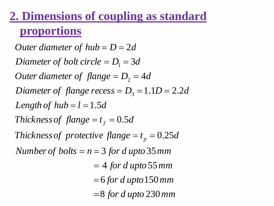
2. Dimensions of coupling as standard
proportions
mmuptodfor
mmuptodfor
mmuptodfor
mmuptodfornboltsofNumber
dtflangeprotectiveofThickness
dtflangeofThickness
dlhubofLength
dDDrecessflangeofDiameter
dDflangeofdiameterOuter
dDcircleboltofDiameter
dDhubofdiameterOuter
p
f
2308
1506
554
353
25.0
5.0
5.1
2.21.1
4
3
2
3
2
1

3. Design of Hub –
The hub is subjected to a torsional shear stress.
Considering it as a hollow shaft.
Givenh
h
safetyFor
D
dkwhere
kDT
)1(16
43

4. Design of Flange –
The flange is subjected to a direct shear at the
junction with the hub.
Givenf
ff
failureshearagainstflangeofsafetytheFor
DDtT
hubofradiusoutsidestresssheardirectareashearT
2

5. Design of Bolts
a) If bolts are fitted in reamed holes –
In such case, the bolts are subjected to a direct
shear stress and crushing stress.
i) Considering the Shearing of bolts –
obtainedbemaydequationthisFrom
DdnT
circleboltofradiusstressshear
boltseachofareashearboltsofnoT
b
bb
24
.
1
2

ii) Considering crushing failure of bolts –
The bolts as well as the contact area of flange are
subjected to crushing stress.
)(
1
2
.
Givencrcrb
crbfb
boltsofsafetyFor
checkedbetoisboltinstresscrushingequationthisFrom
DtdnT
circleboltofradiusstresscrushingflangewithcontactin
bolteachofareaprojectedboltsofnoT

b) If bolts are fitted in large clearance holes –
In such case, the torque is transmitted from one
flange to the other due to friction between them.
Hence, according to uniform intensity of pressure
theory, the torque transmitting capacity of flange
coupling is given by –
22
33
3
2
io
io
rr
rrWnT
2
2
3
2
Drecessflangeofradiusr
Dflangeofradiusouterr
bolteachinpreloadW
flangestwobetweenfrictionoftcoefficien
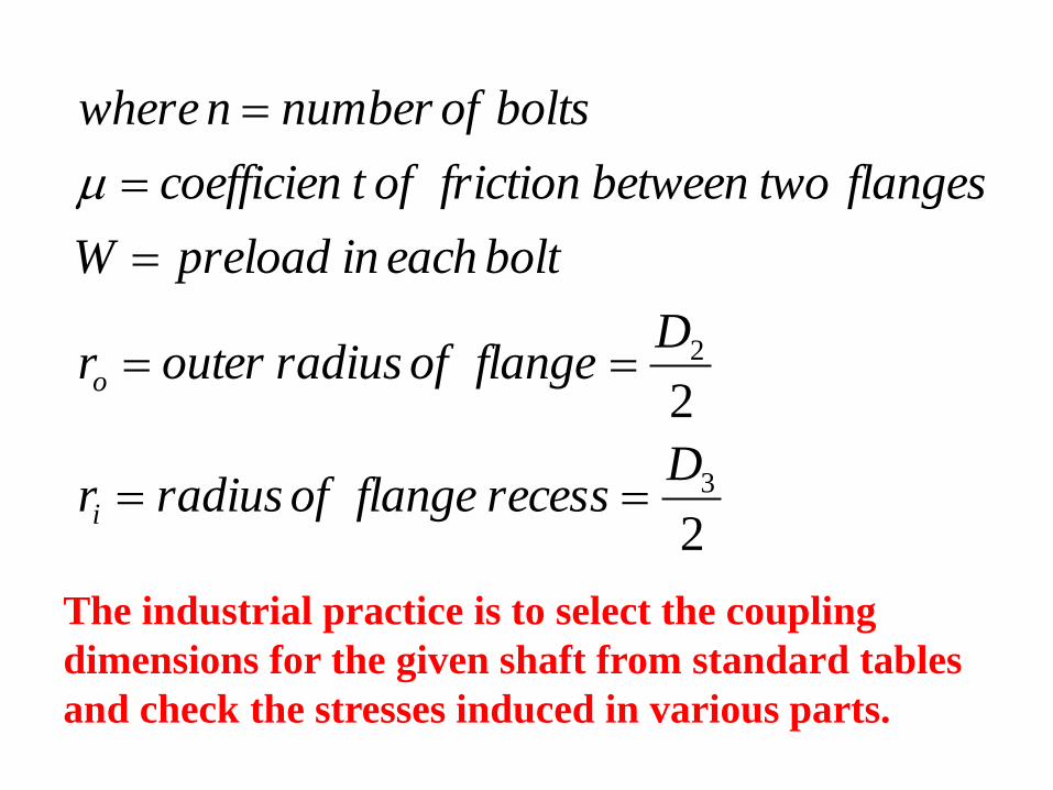
boltsofnumbernwhere
i
o
The industrial practice is to select the coupling
dimensions for the given shaft from standard tables
and check the stresses induced in various parts.

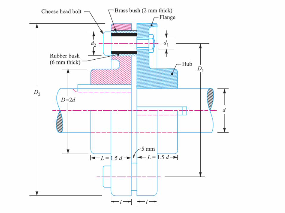
Bushed Pin Type Flexible Coupling
• A bushed-pin flexible coupling, as shown in Fig.
is a modification of the rigid type of flange
coupling.
• The coupling bolts are known as pins.
• The rubber or leather bushes are used over the
pins.
• The two halves of the coupling are dissimilar in
construction.
• A clearance of 5 mm is left between the face of
the two halves of the coupling.

• There is no rigid connection between them and
the drive takes place through the medium of the
compressible rubber or leather bushes.
• In designing the bushed-pin flexible coupling, the
proportions of the rigid type flange coupling are
modified.
• The main modification is to reduce the bearing
pressure on the rubber or leather bushes and it
should not exceed 0.5 N/mm2.
• In order to keep the low bearing pressure, the
pitch circle diameter and the pin size is increased.


pinsofnumbern
bushrubberofdiameterouterd
pinofportionedenlofdiameterd
pinofdiameteralnod
flangeinbushoflengthl
flangeprotectiveofthicknesst
flangeofthicknesst
huboflengthl
flangeofdiameterouterD
circleboltofdiameterD
hubofdiameterouterD
mminshaftofdiameterdLet
b
b
p
f
2
1
2
1
arg
min
,

1. Design of shaft and key –
The shaft and key are designed as discussed in
earlier sections.
2. Dimensions of coupling as standard
proportions –
mmuptodfor
mmuptodfor
mmuptodfor
mmuptodfornpinsofNumber
dtflangeprotectiveofThickness
dtflangeofThickness
dlhuboflength
dDhubofdiameterouter
p
f
1508
1106
754
303
25.0
5.0
5.1
2

3. Design of hub –
The hub is subjected to a torsional shear stress.
Considering it as hollow shaft.
safeishubofdesigntheThen
hubofsafetyFor
hubinstresssheartorsionalWhere
kDT
Givenh
h
h
)(
43
,
)1(16

4. Design of Flange –
The flange is subjected to a direct shear stress at
the junction of the hub.
.
2
)(
safeisflangeofdesigntheThen
shearagainstflangeofsafetyFor
DtDnT
hubofradiusoutsidestresssheardirectareashearT
Givenf
ff

5. Design of pins –
A) Calculate the dimensions of pin
i) Select the number of pins (n)
ii) Nominal diameter of pin
n
ddb
5.0
The standard nominal diameter is selected.

iii) Diameter of enlarged portion of pin (d1) –
The diameter of enlarged portion of
the pin is taken as –
d1=db + 4 mm

iv) Outer diameter of rubber bush (d2) –
It is assumed that the brass bush of 2 mm
thickness and rubber bush of 6 mm thickness are
fitted on the enlarged portion of pin.
Hence, the outer diameter of the rubber bush is –
d2=d1+ (2 x 2) + (2 x 6)
v) Diameter of bolt circle (D1) –
Considering the distance of 8 mm between the
outer surface of hub and the rubber bush.
D1 = D + d2 + (2 x 8)

vi) Length of bush in flange (lb) –
Length of bush in flange is calculated by considering the
bearing pressure on the pin.
Bearing pressure acting on each pin is –
calculatedbecanlequationthisFrom
DldPnT
eqfromFofvaluethePut
DFnT
isdtransmitteTorque
ldPF
pinofareaprojectedpressurebearingF
b
bb
bb
''
2
)1(.
2
)1(
12
1
2

B) Stresses induced in pin –
As each pin is rigidly fastened by nut to one of the
flanges, it acts as a cantilever beam.
The uniformly distributed load acting on the pin is
equivalent to a point load ‘F’ acting at the centre
of length ‘lb’.
Due to this force ‘F’ the pin is subjected to a
bending stress and direct shear stress.

• Bending stress in pin –
2
,
)52
(32
32
)52
(
max
)52
(
..max
1
3
3
Dn
TFWhere
d
lF
d
lF
Z
M
ispininstressbendingimumThe
lFM
ispinonMBimumThe
b
b
b
b
b
b
b
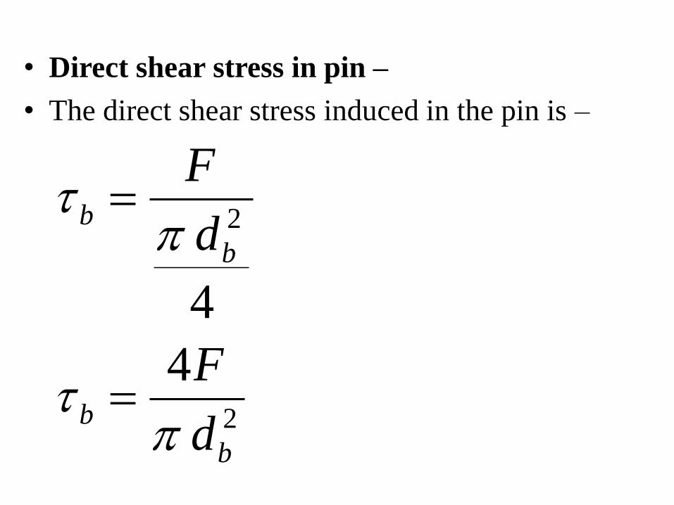
• Direct shear stress in pin –
• The direct shear stress induced in the pin is –
2
2
4
4
b
b
b
b
d
F
d
F

• Principal stress in pin –
• As the pin is subjected to a bending stress and a
direct stress, the maximum shear stress and the
maximum principal stress induced in the pin are
)(max
)(max
22
max
22
max
2(
2
2(
Given
Given
bbb
bb
pinofsafetyfor
and
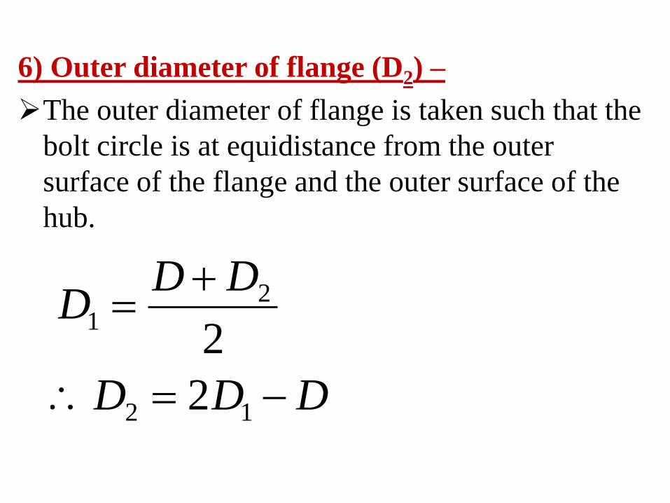
6) Outer diameter of flange (D2) –
The outer diameter of flange is taken such that the
bolt circle is at equidistance from the outer
surface of the flange and the outer surface of the
hub.
DDD
DDD
12
21
2
2

Design of Spur Gears
• Gears are defined as toothed wheels or
multilobed cams which are used to transmit
power and motion from one shaft to another shaft
when the distance between the two shaft is small.
• It is called as positive drive and the velocity ratio
remains constant.
• The gears are transmit large power and are
compact in construction.
• Also they are able to transmit the motion at very
low speed.

Design Considerations for a Gear Drive
• The power to be transmitted.
• The velocity ratio or speed of the gear drive.
• The central distance between the two shaft.
• Input speed of the driving gear.
• The strength of gear teeth so that they will not fail
under static loading or dynamic loading under
normal running condition.
• Wear characteristics of the gear tooth for a long
satisfactory life.
• The use of space and material and cost should be
economical.

Lewis Equation for Static Beam Strength of
Spur Gear Teeth

• Consider each tooth as a cantilever beam
• loaded by a normal load (WN) as shown in Fig.
It is resolved into two components i.e.
tangential component (WT) and radial component
(WR) acting perpendicular and parallel to the
centre line of the tooth respectively.
• The tangential component (WT) induces a
bending stress which tends to break the tooth.
• The radial component (WR) induces a
compressive stress of relatively small magnitude,
therefore its effect on the tooth may be neglected.

• Hence, the bending stress is used as the basis for
design calculations.
• The critical section or the section of maximum
bending stress may be obtained by drawing a
parabola through A and tangential to the tooth
curves at B and C.
• This parabola, as shown dotted in Fig., outlines a
beam of uniform strength, i.e. if the teeth are
shaped like a parabola, it will have the same
stress at all the sections.
• But the tooth is larger than the parabola at every
section except BC.

• We therefore, conclude that the section BC is the
section of maximum stress or the critical section.
• The maximum value of the bending stress (or the
permissible working stress), at the section BC is
given by
hWM
BCtioncriticalofMBMaximumMWhere
I
yM
T
b
sec..,
)1(

gearofwidthFaceb
btI
tooththeoflinecentertheaboutIMI
ttooththeofthicknessHalfy
tooththeofLengthh
tooththeatactingloadTangentialWT
12
..
2
3

.
)..(
var&,
)2(6
6)(
12
2)(
)1(&,
2
2
3
profiletoothitsand
pitchcirculareitooththeofsizetheupon
dependingiablesarehtequationthisIn
h
btW
bt
hW
bt
thW
equationinIyMofvaluesthePut
bT
Tb
T
b

yMbW
yPbW
k
xyPut
kP
PxbW
tconsarekxwhere
Pkh
PxtLet
bT
cbT
c
cbT
c
c
6
6
tan&,
&
,
2
22

• The quantity of ‘y’ is known as Lewis form factor
or tooth form factor and WT is called the beam
strength of the tooth.
• The value of ‘y’ in terms of number of teeth, may
be given by
.20841.0
175.0
.20912.0
154.0
&2
114
684.0124.0
0
0
0
systemstubforT
y
systeminvolutedepthfullforT
y
systeminvolutedepthfullcompositeforT
y

Permissible Working stress (Bending stress) for Gear
Teeth in the Lewis equation
• The permissible working stress in the Lewis
equation depends upon the material for which an
allowable static stress may be determined.
• The allowable static stress is the stress at the
elastic limit of the material.
• It is also called as basic stress.

• The permissible working (bending) stress,
according to Barth formula is –
smupto
velocityandcutaccurateforv
C
smupto
velocityatoperatinggearcarefullyforv
C
smupto
velocityatoperatinggearordinaryforv
C
factorVelocityCwhere
C
V
V
V
V
Vob
/20
6
6
/5.12
5.4
5.4
/5.12
3
3
,

Power Transmission Capacity of Spur
Gear in Bending
• The design tangential tooth (WT) load and power
transmitted (P) and the pitch line velocity is given
by equation.
metersingearofDCPD
factorServiceC
DNsminvelocitylinePitchV
wattindtransmittePowerP
ymbCymbW
NinloadtoothgentialePermissiblWWhere
CV
PW
S
VobT
T
ST
...
60/
)(
tan,

.,
60
60
60
.
mod,
)(
rpminspeedNwhere
NTPV
NTmV
NDV
teethofnumberT
meterinulemwhere
TmDmT
DPpitchCircular
C
C

Modes / Causes of Gear tooth Failure
1. Bending failure or tooth breakage –
Gear tooth behave like a cantilever beam subjected to a
repetitive bending stress. The tooth may break due to
repetitive bending stress.
The tooth breakage occurs when the repetitive bending stress
induced in the gear tooth exceed the bending endurance
strength of the gear tooth.
In other words the tooth breakage occurs when the total load
acting on the gear tooth exceed beam strength of the gear
tooth.
The tooth breakage can be avoided by adjusting the
parameters such as module and face width in the gear design.
2. Wear Failure –
The wear is the phenomenon which removes the
complete layer of the surface or makes craters or
scratches on the surface.
The different types of wear failure in the gear tooth
are discuss below.
a) Pitting –
It is the surface fatigue failure due to repetitive
contact stresses.
The pitting starts when total load acting on the
gear tooth exceeds the wear strength of the gear
tooth.

b) Scoring –
Scoring is essentially a lubrication failure.
In adequate lubrication along with the high tooth
load and poor surface finish result in breakdown
of the oil film and cause the metal to metal
contact.
This causes rapid alteration welding and tearing
at high spots which is known as stick-slip
phenomenon.

c) Abrasive Wear –
Abrasive wear is a surface damage caused by
particles trapped in between the meeting teeth
surfaces.
These particles may be present in lubricant as
impurities, may be the dirt entering the gearbox from
outside or may be flakes of material detached from
the tooth surface.
Abrasive wear may be minimize by proper filtration
of the lubricant, providing complete enclosure for
gear, increasing the surface hardness and use of high
viscosity oils.

d) Corrosive Wear –
The corrosive wear is due to chemical action by
the improper lubricant or sometime it may be due
to surrounding atmosphere which may be
corrosive in nature.
The remedies against corrosive wear are using
proper lubricant with proper additives and
providing complete enclosure for gears.

THE END