3 details of the device under test and the testing procedure
TRANSCRIPT

(R) = Recommendation
3 Details of the device under test and the testing procedure Record/procedure No:
Form of testing: Partial testing Equipment
Control
electrical
Applicant:
Manufacturer:
Device under test:
Type:
Year of manufacture:
Serial No/product No:
Testing performed on (date): At (company):
Testing performed by:
Also present:
List of the safety testing of machines - Electrical equipment -
06.2020

Testing performed against:
IEC 60204-1 2016
(Sub-)clause:
Electrical equipment of machines
(R) = Recommendation
DE
FIC
IT
NO
YE
S
N/A
4 Physical ambient and operating conditions
4.1 Electromagnetic compatibility (EMC) 4.4.2 Refer also to IEC 61000-6-1 IEC 61000-6-2 IEC 61000-6-3 IEC 61000-6-4
1. The incorporated electrical devices and components aresuitable for EMC environments
�
4.4.2 2. The electrical installation and wiring are consistent with theinstructions provided by the manufacturer of the equipment
�
4.2 Ambient air temperature 4.4.3 Ambient air temperature at least +5°C to +40°C or as
specified by the manufacturer �
4.3 Humidity 4.4.4 The electrical equipment operates correctly at a relative humidity
of 50% and a temperature of +40 °C �
4.4.4 Occasional condensation has no harmful effect �
4.4 Altitude 4.4.5 Clearance in air and creepage distances designed for use at
altitudes of up to 1 000 m �
4.5 Contaminants 4.4.6 Degree of protection against contact adequate for the ambient
conditions �
4.6 Ionizing and non-ionizing radiation 4.4.7 Additional measures against radiation if necessary �
4.7 Vibration, shock and bump 4.4.8 Additional measures against undesirable effects if necessary �
4.8 Transportation and storage 4.5 Storage temperature -25 °C to +55 °C (+70 °C for short periods) �
List of the safety testing of machines - Electrical equipment -
06.2020
Testing performed against:
IEC 60204-1 2016
(Sub-)clause:
Electrical equipment of machines
(R) = Recommendation
DE
FIC
IT
NO
YE
S
N/A
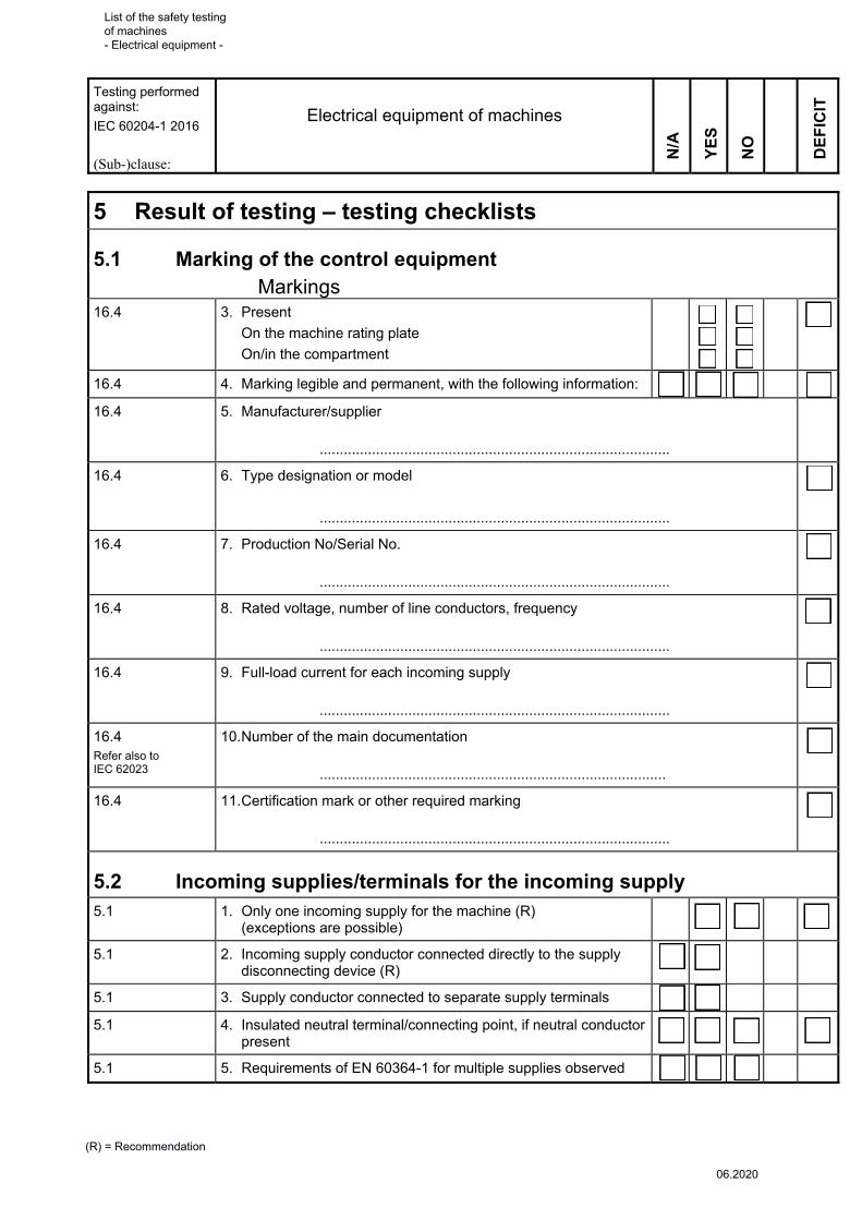
5 Result of testing – testing checklists
5.1 Marking of the control equipment Markings 16.4
3. Present
On the machine rating plate
On/in the compartment
�
16.4 4. Marking legible and permanent, with the following information: � �
16.4 5. Manufacturer/supplier
.......................................................................................
16.4 6. Type designation or model
.......................................................................................
�
16.4 7. Production No/Serial No.
.......................................................................................
�
16.4 8. Rated voltage, number of line conductors, frequency
.......................................................................................
�
16.4 9. Full-load current for each incoming supply
.......................................................................................
�
16.4 Refer also to IEC 62023
10. Number of the main documentation
......................................................................................
�
16.4 11. Certification mark or other required marking
.......................................................................................
�
5.2 Incoming supplies/terminals for the incoming supply 5.1 1. Only one incoming supply for the machine (R)
(exceptions are possible) �
5.1 2. Incoming supply conductor connected directly to the supply disconnecting device (R)
5.1 3. Supply conductor connected to separate supply terminals
5.1 4. Insulated neutral terminal/connecting point, if neutral conductor present
�
5.1 5. Requirements of EN 60364-1 for multiple supplies observed
List of the safety testing of machines - Electrical equipment -
06.2020
Testing performed against:
IEC 60204-1 2016
(Sub-)clause:
Electrical equipment of machines
(R) = Recommendation
DE
FIC
IT
NO
YE
S
N/A
5.1 Refer also to IEC 60445
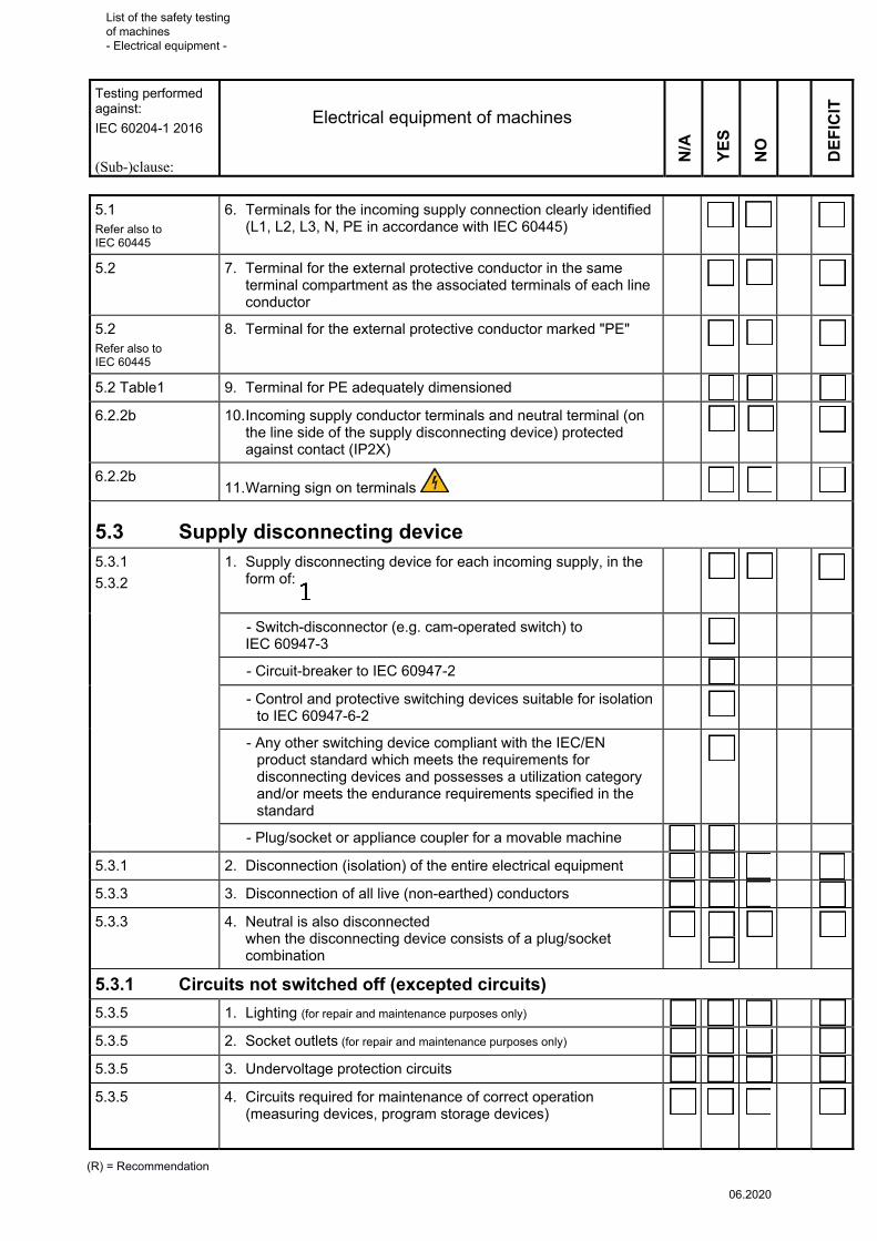
6. Terminals for the incoming supply connection clearly identified (L1, L2, L3, N, PE in accordance with IEC 60445)
�
5.2 7. Terminal for the external protective conductor in the same terminal compartment as the associated terminals of each line conductor
�
5.2
Refer also to IEC 60445
8. Terminal for the external protective conductor marked "PE" �
5.2 Table1 9. Terminal for PE adequately dimensioned �
6.2.2b 10. Incoming supply conductor terminals and neutral terminal (on the line side of the supply disconnecting device) protected against contact (IP2X)
�
6.2.2b 11. Warning sign on terminals
�
5.3 Supply disconnecting device 5.3.1
5.3.2
1. Supply disconnecting device for each incoming supply, in the form of:
�
- Switch-disconnector (e.g. cam-operated switch) to IEC 60947-3
- Circuit-breaker to IEC 60947-2
- Control and protective switching devices suitable for isolation to IEC 60947-6-2
- Any other switching device compliant with the IEC/EN product standard which meets the requirements for disconnecting devices and possesses a utilization category and/or meets the endurance requirements specified in the standard
- Plug/socket or appliance coupler for a movable machine
5.3.1 2. Disconnection (isolation) of the entire electrical equipment �
5.3.3 3. Disconnection of all live (non-earthed) conductors �
5.3.3 4. Neutral is also disconnected when the disconnecting device consists of a plug/socket combination
�
5.3.1 Circuits not switched off (excepted circuits)
5.3.5 1. Lighting (for repair and maintenance purposes only) �
5.3.5 2. Socket outlets (for repair and maintenance purposes only) �
5.3.5 3. Undervoltage protection circuits �
5.3.5 4. Circuits required for maintenance of correct operation (measuring devices, program storage devices)
�
List of the safety testing of machines - Electrical equipment -
06.2020
Testing performed against:
IEC 60204-1 2016
(Sub-)clause:
Electrical equipment of machines
(R) = Recommendation
DE
FIC
IT
NO
YE
S
N/A
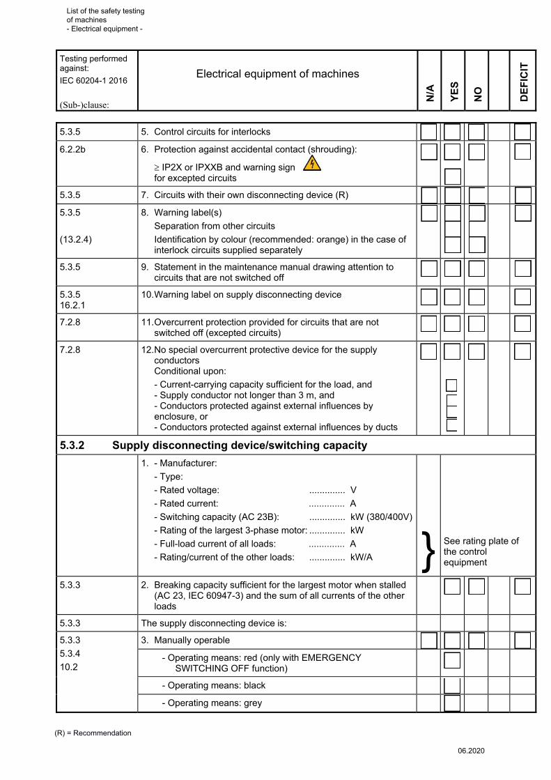
5.3.5 5. Control circuits for interlocks �
6.2.2b 6. Protection against accidental contact (shrouding):
IP2X or IPXXB and warning sign for excepted circuits
�
5.3.5 7. Circuits with their own disconnecting device (R) �
5.3.5
(13.2.4)
8. Warning label(s)
Separation from other circuits
Identification by colour (recommended: orange) in the case of interlock circuits supplied separately
�
5.3.5 9. Statement in the maintenance manual drawing attention to circuits that are not switched off
�
5.3.5 16.2.1
10. Warning label on supply disconnecting device �
7.2.8 11. Overcurrent protection provided for circuits that are not switched off (excepted circuits)
�
7.2.8
12. No special overcurrent protective device for the supply conductors Conditional upon:
- Current-carrying capacity sufficient for the load, and - Supply conductor not longer than 3 m, and - Conductors protected against external influences by enclosure, or - Conductors protected against external influences by ducts
�
5.3.2 Supply disconnecting device/switching capacity
1. - Manufacturer:
- Type:
- Rated voltage: .............. V
- Rated current: .............. A
- Switching capacity (AC 23B): .............. kW (380/400V)
- Rating of the largest 3-phase motor: .............. kW
- Full-load current of all loads: .............. A
- Rating/current of the other loads: .............. kW/A
}
See rating plate of the control equipment
5.3.3 2. Breaking capacity sufficient for the largest motor when stalled (AC 23, IEC 60947-3) and the sum of all currents of the other loads
�
5.3.3 The supply disconnecting device is:
5.3.3
5.3.4
10.2
3. Manually operable �
- Operating means: red (only with EMERGENCY SWITCHING OFF function)
- Operating means: black
- Operating means: grey
List of the safety testing of machines - Electrical equipment -
06.2020

Testing performed against:
IEC 60204-1 2016
(Sub-)clause:
Electrical equipment of machines
(R) = Recommendation
DE
FIC
IT
NO
YE
S
N/A
5.3.3 4. Means to permit locking in the OFF position �
5.3.3 5. Marked I (On) �
5.3.3 6. Marked O (Off) �
5.3.3 7. Only for two switch positions (On/Off) �
5.3.4 8. Operating means external to the enclosure �
5.3.4 9. Operating means easily accessible at a height of between 0.6 m and 1.7 m (max. 1.9 m)
�
5.3.4 10. When the external operating means is not intended for emergency operations:
Colouring grey or black
Door that can be readily opened and is marked appropriately:
Switch-disconnector
or
Circuit-breaker with disconnector properties
�
Supply terminals of main switch:
6.2.2b 11. Protected against contact (IP2X or IPXXB) �
6.2.2b 12. Warning sign on terminals
�
5.3.1 13. Where two main switches are present, protective interlocks are present (where the situation is hazardous)
�
List of the safety testing of machines - Electrical equipment -
06.2020

Testing performed against:
IEC 60204-1 2016
(Sub-)clause:
Electrical equipment of machines
(R) = Recommendation
DE
FIC
IT
NO
YE
S
N/A
5.3.3 Supply disconnecting device in the form of an appliance coupler
5.3.3
13.4.5
Appliance coupler with adequate breaking capacity or additional switching device with adequate breaking capacity
�
13.4.5 First make/last break earthing contact
13.4.5 At rated currents of > 16 A or where a hazardous situation is possible: Interlocking device present to prevent unintended or accidental disconnection
Adequate breaking capacity; where the rated current is ≥ 30 A, interlocked with an additional switching device such that connection or disconnection is possible only with the switching device in the OFF position
13.4.5a) Degree of protection at least IP2X or IPXXB �
13.4.5b) Metallic housings connected to the protective bonding circuit �
13.4.5c) Where disconnection under load is not permitted, an additional switching device is used together with a means to prevent unintended or accidental disconnection
�
13.4.5d) Clear identification of the appliance coupler,
where appropriate with mechanical coding
�
13.4.5e) Appliance couplers used in control circuits satisfy the requirements of IEC 61984
�
5.4 Protection against electric shock
5.4.1 Basic protection
6.2.2 1. Enclosures Compartment 1 ....................................................................
Compartment 2 ....................................................................
Compartment 3 ....................................................................
Refer to the questions in Section 5.5, "Compartments"
6.2.3
2. The insulation of live parts cannot be removed without being destroyed Affected parts of the installation:
………………………………....................................................
...............................................................................................
�
6.2.4 3. Discharge of residual voltages, see Section 5.8, "Further requirements for electrical equipment in the compartment"
�
6.2.5 6.2.6 Refer also to IEC 60364-4-41
4. Protection by barriers, placing out of reach or obstacles on affected parts of systems:
…………………………........................................................
............................................................................................
List of the safety testing of machines - Electrical equipment -
06.2020

Testing performed against:
IEC 60204-1 2016
(Sub-)clause:
Electrical equipment of machines
(R) = Recommendation
DE
FIC
IT
NO
YE
S
N/A
5.4.2 Fault protection
6.3.2.2 1. Protection by the use of class II equipment (with protective insulation) or equivalent insulation
- Complete machine
- Components/parts of the system:
………………………........................................................
........................................................................................
�
6.3.2.3 Refer also to IEC 60364-4-41
2. Electrical separation of an individual circuit only Affected part of the machine: ............................................................................................
�
6.3.3 3. Automatic disconnection of the supply in the event of an insulation fault
�
- All exposed conductive parts connected to the protective bonding circuit (protective potential equalization of the exposed conductive parts)
- Protective equipment for automatic disconnection
Fuses
Residual current protective devices
Relevant requirements of IEC 60364-4-41 for IT systems
6.3.3 4. Protective device appropriate for the system type; requirements met
�
6.3.3 5. Fault protection for the circuits (power drive systems)
5.4.3 Protection by PELV against direct and indirect contact
6.4
1. Affected parts of the installation (circuits)......................................................................... ...............................................................................................
The following requirements of the clause are met
�
6.4.1.a) 2. Max. rated voltage 25 V AC/60 V DC in dry rooms without large-area contact of live parts with the human body
�
6.4.1.a) 3. Max. rated voltage 6 V AC/15 V DC in all other cases �
6.4.1.b) 4. One side of the circuit is connected to the protective bonding circuit
�
6.4.1.c) Refer also to IEC 61558-1 IEC 61558-2-6
5. Electrical separation satisfies that required between the primary and secondary windings of a safety isolating transformer
�
List of the safety testing of machines - Electrical equipment -
06.2020

Testing performed against:
IEC 60204-1 2016
(Sub-)clause:
Electrical equipment of machines
(R) = Recommendation
DE
FIC
IT
NO
YE
S
N/A
6.4.2 Supply for PELV by: �
6. Safety isolating transformer in accordance with IEC 61558-1 and IEC 61558-2-6
�
Marked: FF for fail-safe safety isolating transformer
Marked: for non-short-circuit-proof safety isolating transformer
Marked: for short-circuit-proof safety isolating transformer
6.4.2 7. Switch mode power supply with safety transformers to IEC 61558-2-17 marked in the same way as 6
�
6.4.2 8. Power supply with the same level of safety as a safety isolating transformer (e.g. motor generator with separate windings providing equivalent isolation)
�
6.4.2 9. Electrochemical source of power (e.g. battery) or other source of power (e.g. diesel-driven generator)
�
IEC 61558-1; Clause 8
10. Markings on the source of power:
..............................................................................................
..............................................................................................
..............................................................................................
�
11. Labelling on the circuit diagram:
..................................................................................
�
6.4.1 d) 12. Live parts are reliably separated from the other circuits (e.g. by partitions, insulation for max. voltage, see IEC 60204-1, Sub-clauses 6.3.2.3 and 13.1.3)
�
Where appliance couplers are provided: �
6.4.1.e) 13. Plug and socket are compatible only with appliance couplers for PELV circuits
�
14. Where PELV is used for a control circuit: �
The requirements for control circuits are also met (see 5.9) �
List of the safety testing of machines - Electrical equipment -
06.2020

p
Testing performed against:
IEC 60204-1 2016
Electrical equipment of machines
(Sub-) clause
Requirement
Compartment 1: ……………………..
Compartment 2: ………………
Compartment 3: ……………………..
(R) = Recommendation
DE
FIC
IT
DE
FIC
IT
DE
FIC
IT
YE
S
YE
S
YE
S
NO
NO
NO
N/A
N/A
N/A
5.5 Compartments (protection by enclosure) 16.2.1 1. Compartment
- Clearly recognizable
- Not clearly recognizable
Warning sign present Terminals with warning sign
(black on yellow triangle)
� � �
11.2.2 2. Compartment contains no equipment (including solenoid valves) other than electrical equipment
� � �
5.5.1 Doors/lids
6.2.2a 1. With locking closure
6.2.2a 2. With screw closure
6.2.2a 3. Can be opened only by means of a key or tool
� � �
6.2.2b 4. Where opening is possible without a key or tool, only following disconnection of the live parts from the system (e.g. supply disconnecting device)
� � �
6.2.2c Refer also to IEC 60529
5. Can be opened without a key or tool only when all live parts are reliably shrouded (test finger IP 2X or IP XXB)
� � �
11.4 6. Captive fasteners/screws � � �
11.4 7. Width of door/lid < 0.9 m; opening angle at least 95° (R)
� � �
11.4 8. Vertical hinges on doors, preferably removable (R)
� � �
11.2.1 9. No devices on doors/lids other than devices for operating, indicating, measuring and cooling (fans)
� � �
List of the safety testing of machines - Electrical equipment -
06.2020

p
Testing performed against:
IEC 60204-1 2016
Electrical equipment of machines
(Sub-) clause
Requirement
Compartment 1: ……………………..
Compartment 2: ………………
Compartment 3: ……………………..
(R) = Recommendation
DE
FIC
IT
DE
FIC
IT
DE
FIC
IT
YE
S
YE
S
YE
S
NO
NO
NO
N/A
N/A
N/A
8.2.3 10. On doors and lids on which electrical equipment is mounted: moving protective conductor connections of adequate cross-sectional area, or construction elements with low electrical resistance
� � �
11.4 11. Joints and gaskets fitted permanently and securely
� � �
5.5.2 Degrees of protection
6.2.1 Refer also to
IEC 60529
1. Minimum degree of protection IP2X (12 mm); for upper, readily accessible lids IP4X (1 mm) or IPXXD
� � �
11.3 2. Ventilated enclosures (e.g. containing only motor starter resistors): Minimum degree of protection IP10
� � �
11.3 3. Ventilated enclosures (other equipment) Minimum degree of protection IP32
� � �
11.3 4. Enclosures for general use exhibit an appropriate degree of protection (IP32, IP43, IP54)
� � �
11.3 5. Enclosures cleaned by low-pressure water jets: IP55
� � �
11.3 6. Enclosures providing protection against fine dust: IP65
� � �
11.4 7. Enclosures containing slip-ring assemblies: IP2X
� � �
11.4 8. Penetration of openings by water, dust, oil is prevented, e.g. on - Cable access - Fixing holes - Base apertures (foundation) - Other parts of the machine
� � �
4.4.6 4.4.7
9. Suitability where exposed to acids, corrosive gases, salt, radiation
� � �
List of the safety testing of machines - Electrical equipment -
06.2020

p
Testing performed against:
IEC 60204-1 2016
Electrical equipment of machines
(Sub-) clause
Requirement
Compartment 1: ……………………..
Compartment 2: ………………
Compartment 3: ……………………..
(R) = Recommendation
DE
FIC
IT
DE
FIC
IT
DE
FIC
IT
YE
S
YE
S
YE
S
NO
NO
NO
N/A
N/A
N/A
5.5.3 Accessibility
11.2.1 1. Correct mounting height and location of the terminals and device connections (> 0.2 m above servicing level) (R)
� � �
11.2.1 2. Correct mounting height for devices requiring maintenance or adjustment (0.4 m–2 m)
� � �
11.2.1 3. Ease of access to the switchgear for operation and maintenance from the front
� � �
11.2.1 4. Ease of identification of the devices (without moving the wiring) and facility of removal
� � �
11.2.1 5. Plug-in devices � � �
11.2.1 6. Plug/socket combinations permit unobstructed access
� � �
11.2.1 7. Testing point present � � �
5.5.4 Electric shock protection
6.2.2 1. Where located in the vicinity of live parts, control elements for adjusting/resetting desired functions satisfy IP2X or IPXXB
� � �
6.2.2 - On screw-in fuse links � � �
6.2.2 - On timer elements � � �
6.2.2 - On overcurrent releases � � �
6.2.2 2. Live components on the inside of doors satisfy IP1X or IPXXA (50 mm sphere)
� � �
List of the safety testing of machines - Electrical equipment -
06.2020

p
Testing performed against:
IEC 60204-1 2016
Electrical equipment of machines
(Sub-) clause
Requirement
Compartment 1: ……………………..
Compartment 2: ………………
Compartment 3: ……………………..
(R) = Recommendation
DE
FIC
IT
DE
FIC
IT
DE
FIC
IT
YE
S
YE
S
YE
S
NO
NO
NO
N/A
N/A
N/A
5.5.5 Identification
16.5,
16.2.2 Refer also to ISO 13732-1
Electrical equipment and hot surfaces are marked permanently and clearly according to the technical documentation; affected equipment/hot surfaces for which this is not the case:
.............................................
.............................................
.............................................
� � �
5.6 Wiring within the compartments 13.1.1 1. Means of connection present
for all conductors � � �
13.1.1 2. Terminals suitable for the type and cross-sectional area of the conductors
� � �
13.5.1 3. Conductors laid in suitable ducts
� � �
13.5.1 4. Ducts not over-occupied � � �
13.3 5. Conductors not running in ducts are adequately supported
� � �
13.3 6. Modification of the wiring possible from the front, or from the rear by access doors or swingout panels (R)
� � �
13.3 7. Terminal blocks or plug/socket combinations provided for control wiring extending beyond the enclosure; (cables of power and measuring circuits may be connected directly)
� � �
13.1.1 Refers also to
IEC 61666
8. Terminals marked clearly according to the plans
� � �
13.1.2 9. Cables and conductors of sufficient length for connection and disconnection (applies in particular to protective conductors)
� � �
List of the safety testing of machines - Electrical equipment -
06.2020

p
Testing performed against:
IEC 60204-1 2016
Electrical equipment of machines
(Sub-) clause
Requirement
Compartment 1: ……………………..
Compartment 2: ………………
Compartment 3: ……………………..
(R) = Recommendation
DE
FIC
IT
DE
FIC
IT
DE
FIC
IT
YE
S
YE
S
YE
S
NO
NO
NO
N/A
N/A
N/A
13.1.2 10. Protective conductors placed close to the associated line conductors (R)
� � �
12.2 11. Minimum cross-sectional areas for wiring within enclosures:
� � �
- Power circuits, connections that are not moved: 0.75 mm2
� � �
- Control circuits: 0.2 mm2 � � �
- Data communication systems: 0.08 mm2
� � �
13.1.3 12. Control circuit conductors operating at different voltages laid together (e.g. in a cable duct):
� � �
- All insulated for the highest voltage to which any of the conductors can be subjected, or
� � �
- Separated by suitable barriers
� � �
13.1.1 13. Soldered connections only on terminals suitable for soldering
� � �
Table D.4 Refer also to IEC 60228
14. Solid (single-strand) conductors only for fixed, vibration-free installation
� � �
13.1.2 15. Cables and conductors adequately supported (no mechanical stresses at the terminations)
� � �
13.1.2 16. All conductors run from terminal to terminal (without splices or joints)
� � �
13.1.1 17. Connector sleeves on terminations of stranded conductors
� � �
13.1.1 18. Terminals not obscured by wiring
� � �
13.4.7 19. Spare conductors connected to spare terminals or isolated
� � �
List of the safety testing of machines - Electrical equipment -
06.2020

p
Testing performed against:
IEC 60204-1 2016
Electrical equipment of machines
(Sub-) clause
Requirement
Compartment 1: ……………………..
Compartment 2: ………………
Compartment 3: ……………………..
(R) = Recommendation
DE
FIC
IT
DE
FIC
IT
DE
FIC
IT
YE
S
YE
S
YE
S
NO
NO
NO
N/A
N/A
N/A
5.3.5
(13.2.4)
20. Circuits that are not disconnected by the supply disconnecting device:
� � �
- Warning label present or � � �
- Conductors laid separately, or
� � �
- Conductors identified by colour
� � �
5.3.5 21. Reference in the maintenance manual to circuits that are not disconnected
� � �
13.1.1 22. Fraying of strands prevented on shielded conductors
� � �
13.1.5 23. Conductors between pick-up and pick-up converter of an inductive power supply system:
� � �
- As short as possible � � �
- Adequately protected against mechanical damage
� � �
5.6.1 Connections to equipment on doors
13.3 12.2; 12.6
1. With flexible conductors � � �
13.3 13.5.1
2. Protection against damage (tubing, spiral wrap, etc.)
� � �
13.3 3. Strain relief on the fixed and movable parts
� � �
5.6.2 Identification of conductors
8.2.2
13.2.2
1. Protective conductor: � � �
GREEN-YELLOW over the entire length of the conductor, or
� � �
Clearly distinguishable by shape, location or marking
� � �
13.2.3 2. Neutral conductor: LIGHT BLUE (R)
� � �
13.2.4 Refer also to IEC 60757
3. Identification of conductors by colour
List of the safety testing of machines - Electrical equipment -
06.2020

p
Testing performed against:
IEC 60204-1 2016
Electrical equipment of machines
(Sub-) clause
Requirement
Compartment 1: ……………………..
Compartment 2: ………………
Compartment 3: ……………………..
(R) = Recommendation
DE
FIC
IT
DE
FIC
IT
DE
FIC
IT
YE
S
YE
S
YE
S
NO
NO
NO
N/A
N/A
N/A
13.2.4 4. Power circuits:
BLACK (R) � � �
13.2.4 5. Control circuits (DC):
BLUE (R) � � �
13.2.4 6. Control circuits (AC):
RED (R) � � �
13.2.4 7. Exempted circuits to IEC 60204-1, Sub-clause 5.3.5:
ORANGE (R)
� � �
13.2.4 8. No use of GREEN or YELLOW where a possibility of confusion exists with the GREEN-YELLOW bicolour combination
� � �
13.2.3 9. Where colour is the sole means of identification, LIGHT BLUE is used solely for neutral conductors
� � �
13.2.1 Refer also to
IEC 62491
10. Conductors identifiable at each termination in accordance with the technical documentation, for example by:
- Colour,
- Number,
- Alphanumeric
� � �
List of the safety testing of machines - Electrical equipment -
06.2020

p
Testing performed against:
IEC 60204-1 2016
Electrical equipment of machines
(Sub-) clause
Requirement
Compartment 1: ……………………..
Compartment 2: ………………
Compartment 3: ……………………..
(R) = Recommendation
DE
FIC
IT
DE
FIC
IT
DE
FIC
IT
YE
S
YE
S
YE
S
NO
NO
NO
N/A
N/A
N/A
5.7 Protective bonding circuit 8.2.1
6.3.1
1. All exposed conductive parts and conductive structural parts which may become live in the event of a fault are connected to the protective bonding circuit (for exceptions, see IEC 60204-1, Sub-clause 8.2.1) Separate protective conductor connection for:
� � �
- Cabinet enclosures
- Mounting frames (plates) d)
- Control panels (e.g. anodize
- Electrical equipment and components
- ...........................................
8.2.1 8.2.2 5.2, Table 1
2. In their type, cross-sectional areas and connections, the protective conductors satisfy the electrical and mechanical stresses; if not, affected components: .............................................
.............................................
.............................................
Protective bonding connecting points:
� � �
- On protective bonding bar
- On individual terminals (e.g. spring-loaded terminals)
13.1.1 3. Only one protective conductor connection per terminal connecting point
� � �
13.1.1 4. Protective conductor connections secured against accidental loosening
� � �
List of the safety testing of machines - Electrical equipment -
06.2020

p
Testing performed against:
IEC 60204-1 2016
Electrical equipment of machines
(Sub-) clause
Requirement
Compartment 1: ……………………..
Compartment 2: ………………
Compartment 3: ……………………..
(R) = Recommendation
DE
FIC
IT
DE
FIC
IT
DE
FIC
IT
YE
S
YE
S
YE
S
NO
NO
NO
N/A
N/A
N/A
8.2.4 5. Protective conductor connecting points marked with:
- Symbol
to EN-60417-5019
- Letters PE
- GREEN-YELLOW bicolour combination
8.2.3 6. Current-carrying capacity of connection and bonding points of the protective bonding circuit not impaired by mechanical, chemical or electrochemical influences
� � �
8.2.6 7. Protective conductor connecting points not used for additional fixing purposes (such as supporting rails)
� � �
8.2.3 8. Flexible or rigid cable ducts and metal cable sheathing are not used as protective conductors; they are however connected to the protective bonding circuit
� � �
8.2.3 13.4.5
9. Where plug/socket combinations are employed, the protective bonding circuit is interrupted by a first make last break contact
� � �
8.2.3 10. The protective bonding circuit contains neither switchgear nor overcurrent protective devices
� � �
5.2 11. The protective conductor is among the conductors supplying the equipment (line conductors and protective conductor share common sheathing)
� � �
List of the safety testing of machines - Electrical equipment -
06.2020
p
Testing performed against:
IEC 60204-1 2016
Electrical equipment of machines
(Sub-) clause
Requirement
Compartment 1: ……………………..
Compartment 2: ………………
Compartment 3: ……………………..
(R) = Recommendation
DE
FIC
IT
DE
FIC
IT
DE
FIC
IT
YE
S
YE
S
YE
S
NO
NO
NO
N/A
N/A
N/A
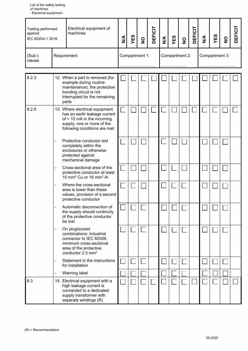
8.2.3 12. When a part is removed (for example during routine maintenance), the protective bonding circuit is not interrupted for the remaining parts
� � �
8.2.6 13. Where electrical equipment has an earth leakage current of > 10 mA in the incoming supply, one or more of the following conditions are met:
� � �
- Protective conductor laid completely within the enclosures or otherwise protected against mechanical damage
- Cross-sectional area of the protective conductor at least 10 mm2 Cu or 16 mm2 Al
- Where the cross-sectional area is lower than these values, provision of a second protective conductor
- Automatic disconnection of the supply should continuity of the protective conductor be lost
- On plug/socket combinations: industrial connector to IEC 60309, minimum cross-sectional area of the protective conductor 2.5 mm2
- Statement in the instructions for installation
- Warning label
8.3 14. Electrical equipment with a high leakage current is connected to a dedicated supply transformer with separate windings (R)
� � �
List of the safety testing of machines - Electrical equipment -
06.2020
Testing performed against:
IEC 60204-1 2016
(Sub-)clause:
Electrical equipment of machines
(R) = Recommendation
NO
YE
S
DE
FIC
IT
N/A
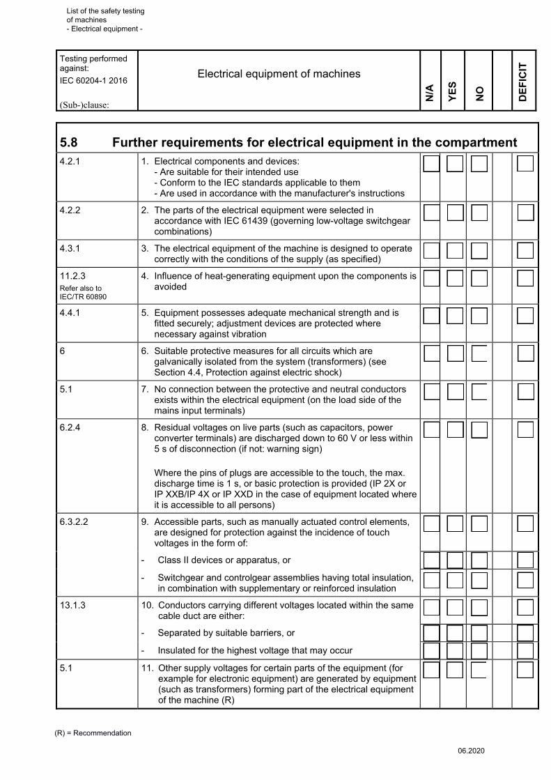
5.8 Further requirements for electrical equipment in the compartment 4.2.1 1. Electrical components and devices:
- Are suitable for their intended use - Conform to the IEC standards applicable to them - Are used in accordance with the manufacturer's instructions
�
4.2.2 2. The parts of the electrical equipment were selected in accordance with IEC 61439 (governing low-voltage switchgear combinations)
�
4.3.1 3. The electrical equipment of the machine is designed to operate correctly with the conditions of the supply (as specified)
�
11.2.3 Refer also to IEC/TR 60890
4. Influence of heat-generating equipment upon the components is avoided
�
4.4.1 5. Equipment possesses adequate mechanical strength and is fitted securely; adjustment devices are protected where necessary against vibration
�
6 6. Suitable protective measures for all circuits which are galvanically isolated from the system (transformers) (see Section 4.4, Protection against electric shock)
�
5.1 7. No connection between the protective and neutral conductors exists within the electrical equipment (on the load side of the mains input terminals)
�
6.2.4 8. Residual voltages on live parts (such as capacitors, power converter terminals) are discharged down to 60 V or less within 5 s of disconnection (if not: warning sign)
Where the pins of plugs are accessible to the touch, the max. discharge time is 1 s, or basic protection is provided (IP 2X or IP XXB/IP 4X or IP XXD in the case of equipment located where it is accessible to all persons)
�
6.3.2.2 9. Accessible parts, such as manually actuated control elements, are designed for protection against the incidence of touch voltages in the form of:
�
- Class II devices or apparatus, or �
- Switchgear and controlgear assemblies having total insulation, in combination with supplementary or reinforced insulation
�
13.1.3
10. Conductors carrying different voltages located within the same cable duct are either:
�
- Separated by suitable barriers, or �
- Insulated for the highest voltage that may occur �
5.1 11. Other supply voltages for certain parts of the equipment (for example for electronic equipment) are generated by equipment (such as transformers) forming part of the electrical equipment of the machine (R)
�
List of the safety testing of machines - Electrical equipment -
06.2020
Testing performed against:
IEC 60204-1 2016
(Sub-)clause:
Electrical equipment of machines
(R) = Recommendation
NO
YE
S
DE
FIC
IT
N/A
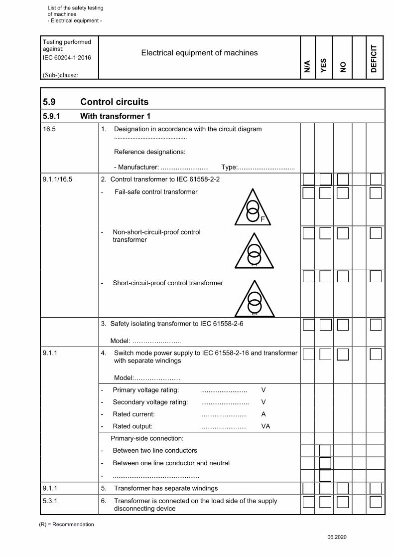
5.9 Control circuits
5.9.1 With transformer 1
16.5 1. Designation in accordance with the circuit diagram ............................................ Reference designations: - Manufacturer: .......................... Type:...............................
9.1.1/16.5 2. Control transformer to IEC 61558-2-2 �
- Fail-safe control transformer �
- Non-short-circuit-proof control transformer
�
- Short-circuit-proof control transformer
�
3. Safety isolating transformer to IEC 61558-2-6
Model: …………..……...
�
9.1.1 4. Switch mode power supply to IEC 61558-2-16 and transformer with separate windings
Model:…………………
�
- Primary voltage rating: ......................... V
- Secondary voltage rating: .......................... V
- Rated current: ……….............. A
- Rated output: ……….............. VA
Primary-side connection:
- Between two line conductors
- Between one line conductor and neutral
- ...............................................
9.1.1 5. Transformer has separate windings �
5.3.1 6. Transformer is connected on the load side of the supply disconnecting device
�
F
List of the safety testing of machines - Electrical equipment -
06.2020

Testing performed against:
IEC 60204-1 2016
(Sub-)clause:
Electrical equipment of machines
(R) = Recommendation
NO
YE
S
DE
FIC
IT
N/A
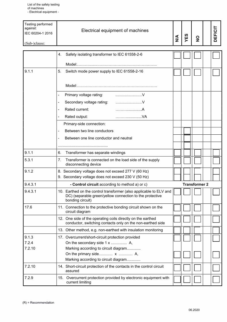
9.1.2 7. Secondary voltage does not exceed 277 V (60 Hz)
8. Secondary voltage does not exceed 230 V (50 Hz)
9. Secondary voltage does not exceed 220 V (DC control circuit)
�
9.4.3.1 - Control circuit according to method a) or c) Transformer 1
9.4.3.1.2 10. Earthed on the control transformer (also applicable to ELV and DC) (separable green/yellow connection to the protective bonding circuit)
�
17.2f 11. Connection to the protective bonding circuit shown on the circuit diagram
�
9.4.3.1.2 12. One side of the operating coils directly on the earthed conductor, switching contacts only on the non-earthed side
�
13. Other method, e.g. non-earthed with insulation monitoring �
9.1.3
7.2.4
7.2.10
14. Overcurrent/short-circuit protection provided
On the secondary side 1 x ............... A,
Marking according to circuit diagram.............
On the primary side............. x ............. A,
Marking according to circuit diagram.............
�
7.2.10 15. Short-circuit protection of the contacts in the control circuit assured
�
7.2.9 16. Overcurrent protection provided by electronic equipment with current limiting
�
5.9.2 With transformer 2
9.1.1 1. Designation in accordance with the circuit diagram:
..............................................................................................
Reference designations:
- Manufacturer: Type:
9.1.1 2. The secondary voltages of multiple transformers are in phase �
9.1.1/16.5 3. Control transformer to IEC 61558-2-2 �
- Fail-safe control transformer �
- Non-short-circuit-proof control transformer
�
- Short-circuit-proof control transformer �
F
List of the safety testing of machines - Electrical equipment -
06.2020
Testing performed against:
IEC 60204-1 2016
(Sub-)clause:
Electrical equipment of machines
(R) = Recommendation
NO
YE
S
DE
FIC
IT
N/A
4. Safety isolating transformer to IEC 61558-2-6
Model:…………..………………………………………….
�
9.1.1 5. Switch mode power supply to IEC 61558-2-16
Model:………………………………………………………
�
- Primary voltage rating: .........................V
- Secondary voltage rating: .........................V
- Rated current: ………..............A
- Rated output: ………..............VA
Primary-side connection:
- Between two line conductors
- Between one line conductor and neutral
...............................................
9.1.1 6. Transformer has separate windings �
5.3.1 7. Transformer is connected on the load side of the supply disconnecting device
�
9.1.2 8. Secondary voltage does not exceed 277 V (60 Hz)
9. Secondary voltage does not exceed 230 V (50 Hz)
�
�
9.4.3.1 - Control circuit according to method a) or c) Transformer 2
9.4.3.1 10. Earthed on the control transformer (also applicable to ELV and DC) (separable green/yellow connection to the protective bonding circuit)
�
17.6 11. Connection to the protective bonding circuit shown on the circuit diagram
�
12. One side of the operating coils directly on the earthed conductor, switching contacts only on the non-earthed side
�
13. Other method, e.g. non-earthed with insulation monitoring �
9.1.3
7.2.4
7.2.10
17. Overcurrent/short-circuit protection provided
On the secondary side 1 x ............... A,
Marking according to circuit diagram.............
On the primary side............. x ............. A,
Marking according to circuit diagram.............
�
�
7.2.10 14. Short-circuit protection of the contacts in the control circuit assured
�
7.2.9 15. Overcurrent protection provided by electronic equipment with current limiting
�
List of the safety testing of machines - Electrical equipment -
06.2020

Testing performed against:
IEC 60204-1 2016
(Sub-)clause:
Electrical equipment of machines
(R) = Recommendation
NO
YE
S
DE
FIC
IT
N/A
5.9.3 Non-earthed control circuits (method b)
9.4.3.1.3 1. 2-pole control switches operating on both conductors �
2. Equipment present for automatic disconnection in the event of an insulation fault
�
5.9.4 Transformer with earthed centre-tap winding (method c)
9.4.3.1.4 1. 2-pole control switches operating on both conductors �
9.4.3.1.4 2. Centre tap connected to protective bonding circuit �
9.4.3.1.4 3. Both conductors are interrupted by the overcurrent protective device
�
5.9.5 Without Transformator (method d)
9.1.1 1. Single motor starter, maximum of 2 control devices �
9.1.3
7.2.4
7.2.10
2. Overcurrent/short-circuit protection provided and protection of the contacts assured
1 x .................... A, (1 line conductor)
Marking according to circuit diagram ………………………………......
2 x .................... A, (2 line conductor)
Marking according to circuit diagram .................................................
�
9.4.3.1.5 3. Two-pole control switch where connection is between two line conductors or between a line conductor and neutral, when phase reversal (e.g. with Schuko-type plug) is possible (for start and stop function and possible hazard)
�
9.4.3.1.5 4. Where connection is made to a non-earthed supply system or IT system, a device must be provided that automatically interrupts the circuit in the event of an earth fault.
�
5.9.6 DC control circuits
9.1.1 1. Where DC control circuits are connected to the protective bonding circuit, they are supplied from a separate winding of the AC control circuit transformer (or a separate transformer for DC supply)
�
5.9.7 Access to switchgear
11.5 1. Doors in gangways for access to electrical operating areas;
- At least 0.7 m wide and 2 m high
- Opening outwards
- Can be opened from inside without keys or tools (e.g. by panic bolts)
�
�
�
�
List of the safety testing of machines - Electrical equipment -
06.2020
Testing performed against:
IEC 60204-1 2016
(Sub-)clause:
Electrical equipment of machines
(R) = Recommendation
NO
YE
S
DE
FIC
IT
N/A
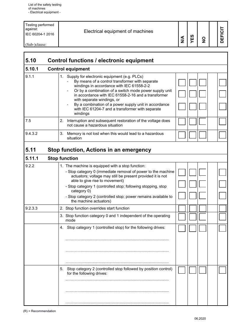
5.10 Control functions / electronic equipment
5.10.1 Control equipment
9.1.1 1. Supply for electronic equipment (e.g. PLCs) - By means of a control transformer with separate
windings in accordance with IEC 61558-2-2 - Or by a combination of a switch mode power supply unit
in accordance with IEC 61558-2-16 and a transformer with separate windings, or
- By a combination of a power supply unit in accordance with IEC 61204-7 and a transformer with separate windings
�
�
�
7.5
2. Interruption and subsequent restoration of the voltage does not cause a hazardous situation
�
9.4.3.2 3. Memory is not lost when this would lead to a hazardous situation
�
5.11 Stop function, Actions in an emergency
5.11.1 Stop function
9.2.2 1. The machine is equipped with a stop function:
- Stop category 0 (immediate removal of power to the machine actuators; voltage may still be present provided it is not able to give rise to movement)
- Stop category 1 (controlled stop; following stopping, stop category 0)
- Stop category 2 (controlled stop; power remains available to the machine actuators)
�
�
�
9.2.3.3 2. Stop function overrides start function �
3. Stop function category 0 and 1 independent of the operating mode
�
4. Stop category 1 (controlled stop) for the following drives:
…………................................................................................
…………................................................................................
…………................................................................................
�
5. Stop category 2 (controlled stop followed by position control) for the following drives:
…………................................................................................
…………................................................................................
…………................................................................................
�
List of the safety testing of machines - Electrical equipment -
06.2020

Testing performed against:
IEC 60204-1 2016
(Sub-)clause:
Electrical equipment of machines
(R) = Recommendation
NO
YE
S
DE
FIC
IT
N/A
9.2.3.3 6. Stop categories satisfy the risk assessment and functional requirements
�
9.2.3.3 7. Stop command effective from any control station where required by the risk assessment
�
9.2.3.4.1
9.2.3.4.2
ISO 13849-1, 5.2.2
8. Manual reset of the stop function does not restart the machinery, but merely permits restarting
�
5.11.2 Measures in an emergency
9.2.3.4.2 Annex E 9.2.3.4.3 Annx E 10.8.1
1. EMERGENCY STOP present (where hazards are presented by machine movements) Protection assured against direct contact, emergency switching off not required
2. EMERGENCY SWITCHING OFF present (where hazards are presented by electrical energy) Use of emergency stop in order to halt movements presenting a hazard is not necessary
3. EMERGENCY STOP and EMERGENCY SWITCHING OFF present Confusion prevented by the following means (e.g. device in a break-glass enclosure): ……………………………………………………………………..
O
O
O
O
O
O
O
O
O
O
O
O
O
O
O
O
O
O
�
�
�
�
�
�
5.11.3 Equipment for EMERGENCY STOP and EMERGENCY SWITCHING OFF
9.2.3.4.2 1. EMERGENCY STOP in the form of stop category 0 or 1 in accordance with the risk analysis
�
10.7.1 2. At all hazard locations (workplace, control station)
Hazard location 1: .................... Stop category: ......................
Hazard location 2: .................... Stop category: ......................
Hazard location 3: .................... Stop category: ......................
Hazard location 4: .................... Stop category: ......................
�
10.7.1 3. Devices for EMERGENCY STOP/EMERGENCY SWITCHING OFF readily accessible
�
ISO 13850, 4.3.3 4. With mechanical latching �
10.7.3 10.8.3
5. Emergency switching off = supply disconnecting device (not with stop categories 1 and 2)
�
10.2.1 6. Red actuator on yellow background �
10.8.2 7. Red push-button operated switch for actuation with the palm or fist, on yellow background
�
10.7.2 Refer also
IEC 60947-5-5
8. Pedal-operated switch without a mechanical guard (for emergency stop only)
�
List of the safety testing of machines - Electrical equipment -
06.2020

Testing performed against:
IEC 60204-1 2016
(Sub-)clause:
Electrical equipment of machines
(R) = Recommendation
NO
YE
S
DE
FIC
IT
N/A
10.7.2
10.8.2
9. Pull-cord operated switch (secure against breakage, disengagement, etc.)
�
9.2.3.4.1 10. Reenergizing possible only following manual resetting of all actuated control elements
�
9.2.3.4.1 11. Resetting does not cause starting �
9.2.3.4.2 12. EMERGENCY STOP overrides all other operating modes �
10.7.2 13. Contact members have positive opening operation (IEC 60947-5-5)
- manufacturer: .........................................................................
- current (AC15-DC13) ................... A at ................ V
- Max. permissible overcurrent protection according to the manufacturer .................. A
- Level of overcurrent protection present .................. A
�
7.2.9 14. Overcurrent protection of the contacts is assured �
15. No operational disconnection by means of EMERGENCY STOP/EMERGENCY SWITCHING OFF
�
16. EMERGENCY SWITCHING OFF / EMERGENCY STOP contacts act upon:
……………………………..............................................................
�
9.2.3.4.3 17. Only electromechanical switching devices employed for EMERGENCY SWITCHING OFF
�
10.7.1 DIN EN ISO 13850, 4.3.8
18. Confusion of active and inactive EMERGENCY STOP devices in mobile operator control stations reduced to a minimum by the following means (e.g. instruction for users): ………………………………………………………………..
�
5.12 Control functions
5.12.1 Devices for removal of power for prevention of unexpected start-up
5.4 1. Present �
5.4 Refer also ISO 14118
2. Device with disconnector function (for disassembly of the machine, work on the electrical installation, adjustment and maintenance work) In the form of: ……………………………………………………..
�
5.4 3. Supply disconnecting device (5.3.2)
5.4 4. Switch-disconnector
5.4 5. Withdrawable fuse links/withdrawable links in locked electrical operating areas
List of the safety testing of machines - Electrical equipment -
06.2020

Testing performed against:
IEC 60204-1 2016
(Sub-)clause:
Electrical equipment of machines
(R) = Recommendation
NO
YE
S
DE
FIC
IT
N/A
5.4 6. Devices that do not satisfy the disconnector function (only for brief inspections, adjustments, limited work on the electrical equipment and without electric shock hazard) In the form of:
……………………………………………………
�
7. Switch, lockable
8. Contactor, de-energized via the control circuit
9. ………………………………………………….
5.12.2 Operation – interlocks – monitoring – start
7.5 1. Interruption and subsequent restoration of power does not lead to a hazardous situation
�
7.6 (9.3.2)
2. Overspeed protection with restart lockout present (if necessary)
�
7.8 3. When the phase sequence of the supply voltage is incorrect:
- A hazardous situation is not possible
- Damage to the machine is not possible
- Protective measure: ................................................................
�
9.3.3 4. Operation of auxiliary functions is monitored �
9.3.5 5. No disconnection as a function of time during reverse current braking (risk of reversed direction of rotation)
�
9.3.5 6. No start-up when the motor shaft is rotated �
9.3.4 7. Interlock against contrary motion �
9.2.3.1 8. Safety functions/protective measures (interlocks) required for safe operation are present
�
9.2.3.1 9. Measures have been taken to prevent commands initiated from different control stations from giving rise to a hazard
�
9.2.3.2 10. Startfunktion wird durch relevanten Stromkreis ausgelöst �
9.2.3.2 11. The start of an operation is possible only when the conditions for machine operation (e.g. guarding) are met
�
9.2.3.2 12. Where more than one control station is required for initiation of starting:
�
- Each control station has its own separate manual start control device
�
- All start control devices are in the rest position (OFF) �
- The required conditions for starting are met prior to the start
�
- Simultaneous actuation (where applicable, selectively by means of selector switches)
�
List of the safety testing of machines - Electrical equipment -
06.2020

Testing performed against:
IEC 60204-1 2016
(Sub-)clause:
Electrical equipment of machines
(R) = Recommendation
NO
YE
S
DE
FIC
IT
N/A
9.2.3.10 13. Combined start-stop devices are used only for functions which do not give rise to a hazardous situation
�
9.3.1 14. Resetting of safeguards (by dropping into the closed position) does not initiate a hazardous start (for guards with start function, see Sub-clause 6.3.3.2.5 of ISO 12100:2010)
�
15. Start commands which give rise to a hazardous situation and are not executed immediately are not stored
�
9.2.3.6 16. Where machine components execute hazardous movements, monitoring is provided for example by overtravel limiters, motor overspeed detection, mechanical overload detection, anti-collision devices
�
9.2.3.6 17. Hazardous movements can be observed from control stations
�
9.2.3.6 18. The operator assumes the task of monitoring in the case of manually guided machines
�
5.12.3 Two-hand control
9.2.3.8 1. Present
9.2.3.8
ISO 13851
2. Type 1:
- Continuous concurrent actuation - When either of the control devices is released: STOP
Safety performance level: well-tried components
�
9.2.3.8
ISO 13851
3. Type 2:
In addition to Type 1: - Both control devices must be released before machine operation can be reinitiated
Safety performance level: single-fault tolerance
�
9.2.3.8
ISO 13851
4. Type 3:
In addition to Type 1 and Type 2: - Synchronous actuation (0.5 s)
Safety performance level:
A = category 1 (well-tried components)
B = category 3 (single-fault tolerance)
C = category 4 (self-monitoring)
�
9.2.3.8
5. Selection of the two-hand control satisfies the risk assessment (refer also to: ISO 13851, "Two-hand control devices")
�
List of the safety testing of machines - Electrical equipment -
06.2020

Testing performed against:
IEC 60204-1 2016
(Sub-)clause:
Electrical equipment of machines
(R) = Recommendation
NO
YE
S
DE
FIC
IT
N/A
5.12.4 Enabling function
9.2.3.9 1. Present
9.2.3.9 2. The enabling control is a manually activated control function interlock which:
�
9.2.3.9 - When activated allows a machine operation to be initiated by a separate start control
�
9.2.3.9 - When de-activated initiates a stop function and prevents initiation of machine operation
�
9.2.3.9 3. The enabling control must be de-activated before operation of the machine can be reinitiated
�
10.9 4. The enabling control device cannot be defeated by simple means
�
10.9 5. Enabling control devices have the following features: ………………………………………………………………………
10.9 6. They are designed in accordance with ergonomic principles �
10.9 7. Type with 2 switch positions:
- Position 1: OFF function (actuator not operated)
- Position 2: Enabling function (actuator operated)
�
10.9 Siehe auch
DIN EN 60947-5-8
8. Type with 3 switch positions:
- Position 1: OFF function (actuator not operated)
- Position 2: Enabling function (actuator is operated in its mid position)
- Position 3: OFF function (actuator is operated past its mid position)
- No activation of the enabling function when the switch is returned from position 3 to position 2
�
List of the safety testing of machines - Electrical equipment -
06.2020

Testing performed against:
IEC 60204-1 2016
(Sub-)clause:
Electrical equipment of machines
(R) = Recommendation
NO
YE
S
DE
FIC
IT
N/A
5.12.5 Cableless control system (CCS)
9.2.4.1 1. A risk assessment shows the CCS to possess suitable functionality and response time
�
9.2.4.1 2. Data transmission reliability requirements for safety functions are met
�
9.2.4.5 3. Unauthorized use of the operator control station is prevented by the following measures: .........................................................
�
9.2.4.5 4. Unambiguous indication of which machine is controlled by the operator control station
�
9.2.4.3 5. Measures are in place to ensure that control commands only
- Act upon the relevant machine
- Act upon the intended machine function
Measure: ................................................................................
�
�
9.2.4.7 Refer also
ISO 13850
Emergency stop devices on CCSs are not the sole measure for initiating an emergency stop function
Confusion between active and inactive emergency stop devices is avoided
�
�
9.2.4.2 6. The ability of a CCS to control the machine is monitored automatically at suitable intervals
�
9.2.4.2 7. Should the communication signal be degraded (e.g. by a reduced signal level, reduced battery power), a warning is provided to the operator
�
9.2.4.2
9.2.4.6
8. Should a CCS be deactivated or its ability to control the machine lost, an automatic stop of the machine is initiated
�
9.2.4.2 9. Restoration of the ability of a CCS to control the machine does not result in restarting of the machine
�
10. Signals relevant to safety and processing of control signals satisfy the risk assessment
�
9.2.4.4 11. Where multiple cableless operator control stations are used:
- Measures are in place to ensure that only one cableless operator control station is enabled at any one time
- Transfer of control between operator control stations requires deliberate manual action on the operator control station
- Transfer of control during operation is possible only if the mode of machine operation is identical on both operator control stations
- Transfer of control cannot result in a change in the mode of machine operation
- Indication provided of which operator control station is controlling which machine
- Indication at suitable locations (risk assessment)
- Stop command effective from each operator control station where shown to be necessary by the risk assessment
�
�
�
�
�
�
�
List of the safety testing of machines - Electrical equipment -
06.2020

Testing performed against:
IEC 60204-1 2016
(Sub-)clause:
Electrical equipment of machines
(R) = Recommendation
NO
YE
S
DE
FIC
IT
N/A
9.2.4.2 12. A change in battery voltage does not give rise to a hazardous situation
Where battery-powered operator control stations may give rise to hazardous movements: warning in the event of a change in battery voltage (specified limits)
Sufficient time available for the machine to be placed in a non-hazardous state
�
�
�
9.2.4.5 13. Selecting a CCS on the machine does not initiate a control command
�
9.2.4.8 14. Restarting the CCS does not reset the emergency-stop condition
�
9.2.4.8 15. The emergency-stop condition cannot be reset until a hazard is no longer present
�
9.2.4.8 16. Fixed reset devices present? (depending upon risk assessment)
�
5.12.6 Operating modes
9.2.3.5 1. Several operating modes present
9.2.3.5 2. Operating mode (in hazardous situations) can be changed by:
Selector switch:- Lockable cam switch
- Key operated switch, lockable in all positions
- Access code
- ................................................................
�
9.2.3.5 3. Selected operating mode clearly identifiable �
9.2.3.5 4. Operating mode selector switch does not initiate machine operation; separate action required
�
9.2.3.5 5. Relevant safety functions/protective measures are active in all operating modes
�
List of the safety testing of machines - Electrical equipment -
06.2020

Testing performed against:
IEC 60204-1 2016
(Sub-)clause:
Electrical equipment of machines
(R) = Recommendation
NO
YE
S
DE
FIC
IT
N/A
9.3.6
6. Where the safety functions/protective measures must be suspended, the control or operating mode selector simultaneously:
Disables all other operating modes
Permits operation only by means of an enabling device
- Hold-to-run mode (dead-man's circuit)
- Enabling circuit
- Two-hand control
- Portable control unit with emergency switching off
- Cableless control station
Permits operation of hazardous elements only under
reduced risk conditions
- Reduced speed
V = ............... mm/s
Type of speed reduction
...........................................................................................
- Reduced energy
- Limitation of the range of movement
Any operation of hazardous functions by voluntary or involuntary action on the machine's sensors is prevented
- ...........................................................................................
�
4.1 Refer also
ISO 13849-1
Design of the operating mode selector, form of speed reduction, disabling of the guard (6)
- Satisfy the risk assessment
�
Satisfy the requirements for this type of machine (Type C standard („...............................................................................“)
�
List of the safety testing of machines - Electrical equipment -
06.2020

Testing performed against:
IEC 60204-1 2016
(Sub-)clause:
Electrical equipment of machines
(R) = Recommendation
NO
YE
S
DE
FIC
IT
N/A
5.12.7 Control function in the event of a fault
9.4.1 1. The performance of the control system as determined satisfies the following Performance Level in accordance with ISO 13849-1 (Table 2)/SIL in accordance with IEC 62061:
PL/SIL …..... for ........................................................................ (part of the safety function)
PL/SIL …..... for ........................................................................ (part of the safety function)
PL/SIL ........ for ......................................................................... (part of the safety function)
PL/SIL ....... for .......................................................................... (part of the safety function)
�
9.4.1 2. Determining of the required performance of the control system by means of:
- Specified Type C standard Titel................................................................................
- Risk assessment to ISO 13849-1
- Risk assessment to IEC 62061
- ......................................................................................
�
3. The determined Performance Level (1) satisfies the above requirements (2)
�
9.4.1 4. Memory is retained by batteries - If so: does removal or failure of the batteries result in a safe state?
....................................................................................................
�
9.4.1 5. Memory alteration possible only by authorized persons
Protection afforded by: Key
Access code
Tool
�
List of the safety testing of machines - Electrical equipment -
06.2020

Testing performed against:
IEC 60204-1 2016
(Sub-)clause:
Electrical equipment of machines
(R) = Recommendation
NO
YE
S
DE
FIC
IT
N/A
5.12.8 Measures for risk reduction in the event of a fault
9.4.2.2 1. The measure of proven circuit techniques and components includes
- Earthed control circuit
- Connection of the control devices in accordance with IEC 60204-1, Sub-clause 9.4.3.1.1
- Stopping by de-energizing
- Disconnection of all live conductors in the control circuit
- Use of switching devices with direct opening action
- Circuit design to reduce the possibility of faults causing undesirable operations
- Monitoring by:
- Use of mechanically linked contacts (IEC 60947-5-1)
- Use of mirror contacts (IEC 60947-4-1)
�
9.4.2.3 2. Redundancy �
9.4.2.4 3. Diversity
- Use of a combination of normally open and normally closed contacts
- Use of control devices of different types in the control circuit
- Combination of electromechanical and electronic circuits in redundant configurations
- Combination of electrical and non-electrical systems (for example mechanical, hydraulic, pneumatic)
�
9.4.2.5 4. Functional test
- Performed automatically by the control system, at intervals
of: ....................................................................................
- Performed manually during inspections or start-up testing, at intervals of:
....................................................................................
�
5. Behaviour in the event of a fault is appropriate in consideration of the risk
�
5.13 Control and signalling devices 10.1.2 1. Within easy reach (at a height of ≥ 0.6 m) �
10.1.2 2. Can be operated safely �
10.1.1 10.6
3. The danger of inadvertent actuation is low, particularly for start functions
�
10.1.3 Refer also to
IEC 60529
4. Protected against external influences (aggressive liquids, vapours, gases; swarf, particulate matter, foreign objects), e.g. IP 54/IP 55; protection against contact with live parts: IP XXD
�
10.1.2 5. Foot-operated control devices can be operated in the normal working position
�
List of the safety testing of machines - Electrical equipment -
06.2020
Testing performed against:
IEC 60204-1 2016
(Sub-)clause:
Electrical equipment of machines
(R) = Recommendation
NO
YE
S
DE
FIC
IT
N/A
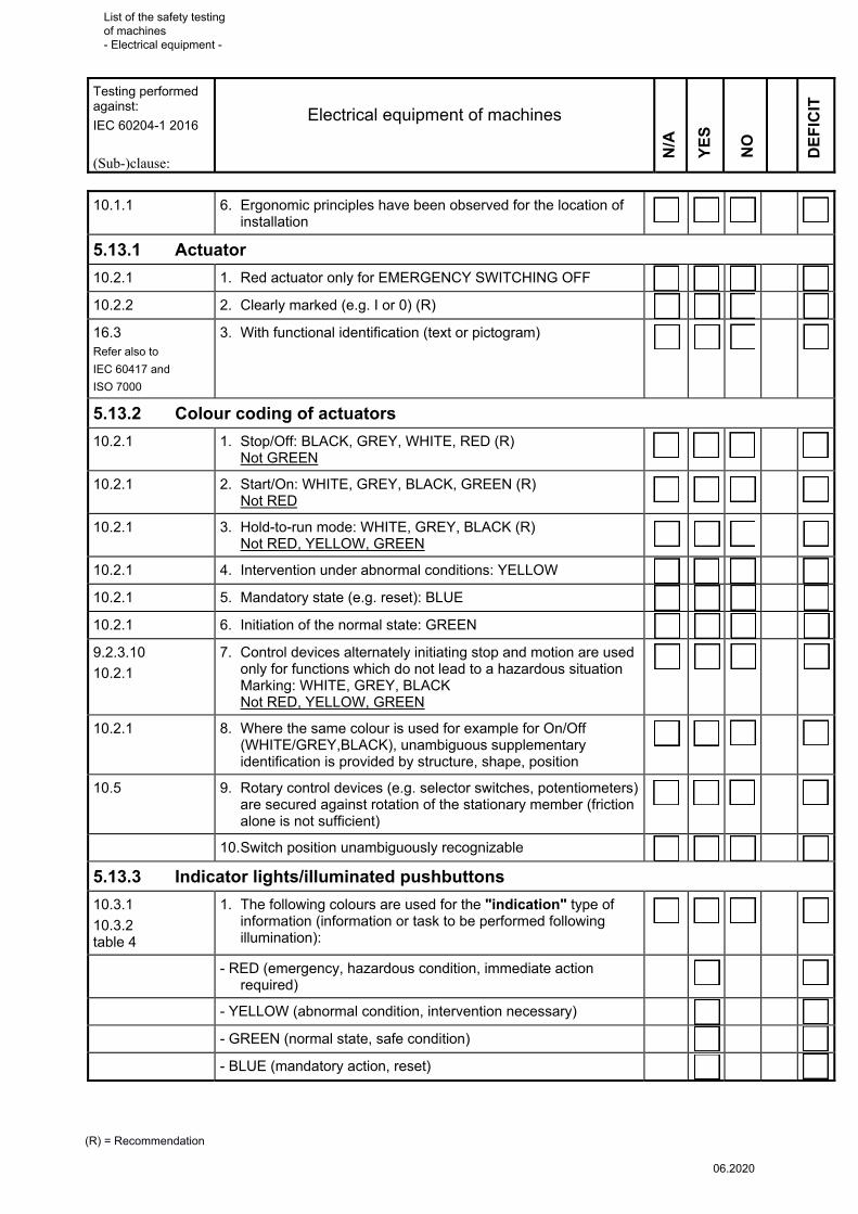
10.1.1 6. Ergonomic principles have been observed for the location of installation
�
5.13.1 Actuator
10.2.1 1. Red actuator only for EMERGENCY SWITCHING OFF �
10.2.2 2. Clearly marked (e.g. I or 0) (R) �
16.3 Refer also to
IEC 60417 and
ISO 7000
3. With functional identification (text or pictogram) �
5.13.2 Colour coding of actuators
10.2.1 1. Stop/Off: BLACK, GREY, WHITE, RED (R) Not GREEN
�
10.2.1 2. Start/On: WHITE, GREY, BLACK, GREEN (R) Not RED
�
10.2.1 3. Hold-to-run mode: WHITE, GREY, BLACK (R) Not RED, YELLOW, GREEN
�
10.2.1 4. Intervention under abnormal conditions: YELLOW �
10.2.1 5. Mandatory state (e.g. reset): BLUE �
10.2.1 6. Initiation of the normal state: GREEN �
9.2.3.10
10.2.1
7. Control devices alternately initiating stop and motion are used only for functions which do not lead to a hazardous situation Marking: WHITE, GREY, BLACK Not RED, YELLOW, GREEN
�
10.2.1
8. Where the same colour is used for example for On/Off (WHITE/GREY,BLACK), unambiguous supplementary identification is provided by structure, shape, position
�
10.5 9. Rotary control devices (e.g. selector switches, potentiometers) are secured against rotation of the stationary member (friction alone is not sufficient)
�
10. Switch position unambiguously recognizable �
5.13.3 Indicator lights/illuminated pushbuttons
10.3.1
10.3.2 table 4
1. The following colours are used for the "indication" type of information (information or task to be performed following illumination):
�
- RED (emergency, hazardous condition, immediate action required)
�
- YELLOW (abnormal condition, intervention necessary) �
- GREEN (normal state, safe condition) �
- BLUE (mandatory action, reset) �
List of the safety testing of machines - Electrical equipment -
06.2020
Testing performed against:
IEC 60204-1 2016
(Sub-)clause:
Electrical equipment of machines
(R) = Recommendation
NO
YE
S
DE
FIC
IT
N/A
10.3.1 10.3.2 table 4
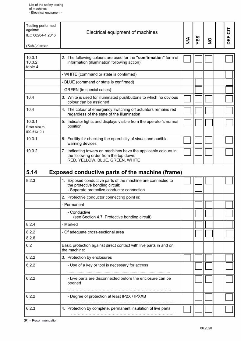
2. The following colours are used for the "confirmation" form of information (illumination following action):
�
- WHITE (command or state is confirmed) �
- BLUE (command or state is confirmed) �
- GREEN (in special cases) �
10.4 3. White is used for illuminated pushbuttons to which no obvious colour can be assigned
�
10.4 4. The colour of emergency switching off actuators remains red regardless of the state of the illumination
�
10.3.1 Refer also to
IEC 61310-1
5. Indicator lights and displays visible from the operator's normal position
�
10.3.1 6. Facility for checking the operability of visual and audible warning devices
�
10.3.2 7. Indicating towers on machines have the applicable colours in the following order from the top down: RED, YELLOW, BLUE, GREEN, WHITE
�
5.14 Exposed conductive parts of the machine (frame) 8.2.3 1. Exposed conductive parts of the machine are connected to
the protective bonding circuit: - Separate protective conductor connection
�
2. Protective conductor connecting point is:
- Permanent �
- Conductive (see Section 4.7, Protective bonding circuit)
�
8.2.4 - Marked �
8.2.2
8.2.6
- Of adequate cross-sectional area �
6.2 Basic protection against direct contact with live parts in and on the machine:
6.2.2 3. Protection by enclosures �
6.2.2 - Use of a key or tool is necessary for access
...........................................................................................
�
6.2.2 - Live parts are disconnected before the enclosure can be opened
…………………………………………………………………..
�
6.2.2 - Degree of protection at least IP2X / IPXXB …………………………………………………………………..
�
6.2.3 4. Protection by complete, permanent insulation of live parts …………………………………………………………………..
�
List of the safety testing of machines - Electrical equipment -
06.2020

Testing performed against:
IEC 60204-1 2016
(Sub-)clause:
Electrical equipment of machines
(R) = Recommendation
NO
YE
S
DE
FIC
IT
N/A
6.2.6 Siehe auch
IEC 60364-4-41
5. Protection by placing out of reach or by obstacles …………………………………………………………………..
�
6.4 6. Basic protection; for indirect contact, protection by the use of PELV
…………………………………………………………………..
(see Section 4.4, Protection against electric shock)
�
5.15 Electrical controlgear on the machine
5.15.1 Controlgear (position switches, pressure switches, encoders)
10.1.3 13.4.1 Refer also to
IEC 60529
1. Possesses a degree of protection (IP), including cable access, which provides suitable protection against the ingress of contaminants (such as swarf, dust, foreign objects)
�
10.1.3 2. Is protected against the influence of aggressive liquids, vapours or gases
�
10.1.2 3. Is readily accessible for service and maintenance �
10.1.2 4. Is mounted in such a manner that it cannot be damaged by activities on the machine (e.g. material transport)
�
6.3.2 5. Possesses total insulation (including cable glands), or �
6.3.3
6.4
6. Features protective conductor connections (also applies to extra-low voltage, except PELV) Where this is not the case, affected devices: ..............................................................................................
..............................................................................................
..............................................................................................
�
11.2.1 7. The association between plug-in control devices is made clear by distinctive type (e.g. shape, marking, reference designation)
�
5.15.2 Position sensors (position switches, proximity switches)
9.3.2 1. Exceeding of an operating limit (position, end position) is prevented by:
�
9.3.2 - A mechanical device
9.3.2 - Integration of position sensors into the control system
10.1.4 2. Position sensors are arranged such that they are not damaged in the event of overtravel
�
List of the safety testing of machines - Electrical equipment -
06.2020

Testing performed against:
IEC 60204-1 2016
(Sub-)clause:
Electrical equipment of machines
(R) = Recommendation
NO
YE
S
DE
FIC
IT
N/A
10.1.4 3. Position sensors in circuits with safety-related control functions take the form of:
�
10.1.4 - Mechanical position switches with direct opening action in accordance with IEC 60947-5-1
�
10.1.4 - Proximity switches with a comparable level of safety in accordance with IEC 60947-5-3
�
4. Control element is actuated by rigid mechanical parts (not springs)
�
DGUV-I 203-079
5.2
5. Position switches, control elements and operating elements are secured against changes in position (by spring washers, serrated lock washers, fixing pins)
�
DGUV-I 203-079
5.1
6. Adequate actuation stroke �
DGUV-I 203-079
5.1
7. Switching off/stopping before access to danger zones is possible
�
DGUV-I 203-079 8. Mechanical position switches employed for safety purposes are selected and fitted in accordance with the requirements (see table)
�
DGUV-I 203-079
5.3
9. Position switches are safeguarded against inadvertent actuation
�
Position sensors (position switches) for personnel protection
Location of use
Marking according
to plan
Manufacturer Type Positive actuation (break contact) element
category 1 category 2
No positive actuation
(make contact) element Cat. 1
IEC 60947-5-1
....................
Test mark
1. /
2. /
3. /
4. /
5. /
6. /
7. /
5.16 Conductors (terminal boxes and plug/socket combinations) outside the compartments
1. Conductors in the form of light plastic-sheathed cable �
13.4.1 2. Conductors of a circuit are not distributed separately (multi-core cables, cable ducting systems, etc.)
List of the safety testing of machines - Electrical equipment -
06.2020

Testing performed against:
IEC 60204-1 2016
(Sub-)clause:
Electrical equipment of machines
(R) = Recommendation
NO
YE
S
DE
FIC
IT
N/A
13.4.1 3. Means of introduction, cable glands, etc. do not reduce the degree of protection of the enclosure
�
13.4.2 4. Single-core cables and connections in cable ducts/conduits �
12.3 5. Electric strength of the insulation at least 2 000 V AC, 5 minutes at voltages > 50 V AC or 120 V DC (PELV circuits laid separately: 500 V)
�
13.4.2 6. Conductors from devices with dedicated cables are sufficiently short and located or protected such that the risk of damage is minimized
�
5.16.1 Light plastic-sheathed cable
13.5 1. Protected against mechanical damage �
13.5.1 2. No sharp edges �
13.5.1 3. Protected against oil, temperature, chemical influences, etc.
�
5.16.2 Single-core cables in cable ducts/trunking
13.5.1 1. Cable ducts have a suitable degree of protection �
13.5.1 2. No sharp edges, rough surfaces, etc. �
13.5.1 3. No mechanical damage to the duct; secure fixing �
13.5.1 4. Ducts are not over-occupied (R) �
13.5.1 5. Cable conduits are not laid together with oil and water lines, or clear marking (R)
�
13.5.2 13.5.4
6. Cable conduits are of suitable type, corrosion-resistant, e.g. galvanized steel
5.16.3 Moveable conductors
13.4.3 1. Are flexible, multistranded, and exhibit high bending fatigue strength
�
2. Are protected by:
13.4.3 - Flexible metal tubes
13.4.3 - Plastic tubing
13.4.3 - Special conductor type
13.4.3 3. No tensile or tight-radius bending stress (e.g. on cable glands) �
13.4.3 4. Bending radius ≥ 10 × outside diameter �
13.4.3 5. Space of ≥ 25 mm or fixed barriers between cables subject to movement and moving machine parts
�
13.4.3 6. Flexible metal protective tubing is not used for connections subject to rapid and frequent movement
�
List of the safety testing of machines - Electrical equipment -
06.2020
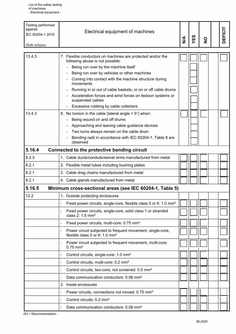
Testing performed against:
IEC 60204-1 2016
(Sub-)clause:
Electrical equipment of machines
(R) = Recommendation
NO
YE
S
DE
FIC
IT
N/A
13.4.3 7. Flexible conductors on machines are protected and/or the following abuse is not possible:
Being run over by the machine itself
Being run over by vehicles or other machines
Coming into contact with the machine structure during movements
Running in or out of cable baskets, or on or off cable drums
Acceleration forces and wind forces on festoon systems or suspended cables
Excessive rubbing by cable collectors
�
13.4.3 8. No torsion in the cable (lateral angle < 5°) when:
Being wound on and off drums
Approaching and leaving cable guidance devices
Two turns always remain on the cable drum
Bending radii in accordance with IEC 60204-1, Table 8 are observed
�
5.16.4 Connected to the protective bonding circuit
8.2.3 1. Cable ducts/conduits/swivel arms manufactured from metal �
8.2.1 2. Flexible metal tubes including bushing plates �
8.2.1 3. Cable drag chains manufactured from metal �
8.2.1 4. Cable glands manufactured from metal �
5.16.5 Minimum cross-sectional areas (see IEC 60204-1, Table 5)
12.2 1. Outside protecting enclosures
- Fixed power circuits, single-core, flexible class 5 or 6: 1.0 mm² �
- Fixed power circuits, single-core, solid class 1 or stranded class 2: 1.5 mm²
�
- Fixed power circuits, multi-core: 0.75 mm² �
- Power circuit subjected to frequent movement, single-core, flexible class 5 or 6: 1.0 mm²
�
- Power circuit subjected to frequent movement, multi-core: 0.75 mm²
�
- Control circuits, single-core: 1.0 mm² �
- Control circuits, multi-core: 0.2 mm² �
- Control circuits, two-core, not screened: 0.5 mm² �
- Data communication conductors: 0.08 mm² �
2. Inside enclosures
- Power circuits, connections not moved: 0.75 mm² �
- Control circuits: 0.2 mm² �
- Data communication conductors: 0.08 mm² �
List of the safety testing of machines - Electrical equipment -
06.2020
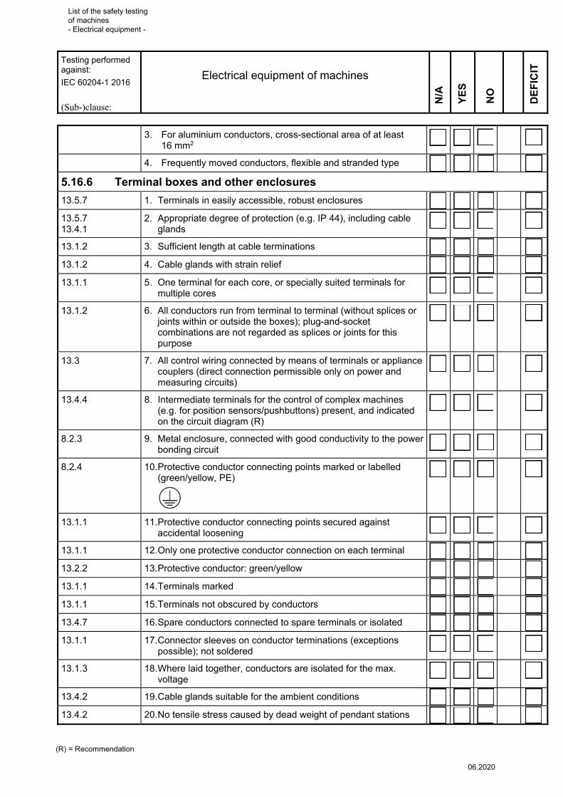
Testing performed against:
IEC 60204-1 2016
(Sub-)clause:
Electrical equipment of machines
(R) = Recommendation
NO
YE
S
DE
FIC
IT
N/A
3. For aluminium conductors, cross-sectional area of at least 16 mm2
�
4. Frequently moved conductors, flexible and stranded type �
5.16.6 Terminal boxes and other enclosures
13.5.7 1. Terminals in easily accessible, robust enclosures �
13.5.7 13.4.1
2. Appropriate degree of protection (e.g. IP 44), including cable glands
�
13.1.2 3. Sufficient length at cable terminations �
13.1.2 4. Cable glands with strain relief �
13.1.1 5. One terminal for each core, or specially suited terminals for multiple cores
�
13.1.2 6. All conductors run from terminal to terminal (without splices or joints within or outside the boxes); plug-and-socket combinations are not regarded as splices or joints for this purpose
�
13.3 7. All control wiring connected by means of terminals or appliance couplers (direct connection permissible only on power and measuring circuits)
�
13.4.4 8. Intermediate terminals for the control of complex machines (e.g. for position sensors/pushbuttons) present, and indicated on the circuit diagram (R)
�
8.2.3 9. Metal enclosure, connected with good conductivity to the power bonding circuit
�
8.2.4 10. Protective conductor connecting points marked or labelled (green/yellow, PE)
�
13.1.1 11. Protective conductor connecting points secured against accidental loosening
�
13.1.1 12. Only one protective conductor connection on each terminal �
13.2.2 13. Protective conductor: green/yellow �
13.1.1 14. Terminals marked �
13.1.1 15. Terminals not obscured by conductors �
13.4.7 16. Spare conductors connected to spare terminals or isolated �
13.1.1 17. Connector sleeves on conductor terminations (exceptions possible); not soldered
�
13.1.3 18. Where laid together, conductors are isolated for the max. voltage
�
13.4.2 19. Cable glands suitable for the ambient conditions �
13.4.2 20. No tensile stress caused by dead weight of pendant stations �
List of the safety testing of machines - Electrical equipment -
06.2020

Testing performed against:
IEC 60204-1 2016
(Sub-)clause:
Electrical equipment of machines
(R) = Recommendation
NO
YE
S
DE
FIC
IT
N/A
13.1.4 Refer also to
IEC 60364-5-52
21. Single-core cables armoured by steel wire or steel tape are not used for AC circuits
�
13.1.4 Refer also to
IEC 60364-5-52
22. Conductors of AC circuits are not enclosed separately in enclosures of ferromagnetic material
�
5.16.7 Appliance couplers; requirements do not apply to bus systems 13.4.5 1. Supply side on the protected sockets �
13.4.5 8.2.3
2. Protective conductor connection (pin) with first-make contact at insertion and last-break contact at withdrawal
�
13.4.5 b) 3. Metallic housings are connected to the protective bonding circuit (not on PELV)
�
13.4.5 4. Contact with live parts not possible during insertion or withdrawal
�
13.4.5 5. Appliance couples possess retaining means (in order to prevent unintended disconnection):
13.4.5 - Where rated currents exceed 16 A �
13.4.5 - When disconnection may give rise to a hazardous situation �
13.4.5 c) - When not intended to be disconnected under load; clear marking to this effect is also necessary
�
13.4.5 6. Appliance couplers which are intended to be connected and disconnected under load must possess adequate load switching capacity; where the appliance coupler is rated at 30 A or greater, connecting and disconnecting under load must be prevented
�
13.4.5 d) 7. Clear identification of appliance couplers (ideally in addition with mechanical coding) where several such combinations are used
�
13.4.5 8. Where appliance couplers in accordance with IEC 60309-1 are employed in control circuits, only contacts which are intended for these purposes are used. Exemption from this requirement: HF signals superimposed on power circuits
�
13.4.5 a) 9. Parts which remain under voltage following disconnection possess a degree of protection of at least IP 2X or IP XXB. Exemption from this requirement: PELV
�
13.4.5 e) 10. Plug/socket combinations in control circuits satisfy the requirements of IEC 61984
�
7.2.5 11. Overcurrent protection in all live (non-earthed) conductors feeding socket circuits
�
Note: one or more of these requirements must be met
List of the safety testing of machines - Electrical equipment -
06.2020

Testing performed against:
IEC 60204-1 2016
(Sub-)clause:
Electrical equipment of machines
(R) = Recommendation
NO
YE
S
DE
FIC
IT
N/A
5.17 Conductor wires and slip-ring assemblies 12.7.1 1. Basic protection assured by:
- Partial insulation of the live parts - Enclosures or barriers with a degree of protection of at least
IP2X or IPXXB
�
�
12.7.1 2. Horizontal top surfaces of barriers or enclosures which are easily accessible possess a degree of protection of at least IP 4X or IP XXD
�
12.7.1 3. Protection by placing out of reach in conjunction with switching-off in an emergency situation
�
12.7.1 4. Conductor wires and bars arranged or protected such that:
Where conductor wires and bars are unprotected, contact with conductive parts is not possible
Swinging loads are not able to cause damage
�
�
12.7.2 5. Protective conductors do not carry current �
12.7.2 6. Protective conductors and neutral conductors have separate conductor wires/bars and slip-rings
�
12.7.2 7. Continuity of the protective bonding circuit assured by the application of suitable measures (such as duplication of the current collectors, continuity monitoring)
�
12.7.3 8. Protective conductor current collectors are not interchangeable with other current collectors
�
12.7.4 9. Removable current collectors with switch-disconnector function possess a protective bonding circuit with late-break disconnection and early-make restoration of continuity
�
12.7.5 10. Clearances correspond to overvoltage category III (see IEC 60664-1)
�
12.7.6 11. Creepage distances: In abnormally dusty, moist or corrosive environments:
Unprotected conductor wires/bars and slip-ring assemblies possess insulators with a creepage distance of at least 60 mm
Enclosed conductor wires, insulated multipole conductor wires and insulated individual conductor bars have creepage distances of at least 30 mm
�
�
�
12. Manufacturers' recommendations concerning gradual deterioration in the insulation values are observed
�
12.7.7 13. Where the conductor wires or conductor bars are arranged such that they can be divided into sections: The energization of adjacent sections by the current collectors themselves is prevented
�
12.7.8 14. Conductor wires/bars and slip-ring assemblies for power circuits are arranged in separate groups to those for control circuits
�
List of the safety testing of machines - Electrical equipment -
06.2020

Testing performed against:
IEC 60204-1 2016
(Sub-)clause:
Electrical equipment of machines
(R) = Recommendation
NO
YE
S
DE
FIC
IT
N/A
12.7.8 15. Conductor wires/bars and slip-ring assemblies are short-circuit proof
�
12.7.8 16. Where slip-ring systems are laid underground or underfloor:
- Removable covers cannot be removed without the aid of a tool
- Metal covers are bonded together and earthed
�
�
12.7.8 17. Where conductor bars are located in common metal enclosures, individual enclosure sections are bonded together and earthed at multiple points
�
12.7.8 18. Conductor bar ducts have drainage facilities �
12.7.8 19. Covers or cover plates of metal enclosures or underground ducts are earthed
�
12.7.8 20. Continuity of protective bonding circuits involving metal hinges is assured
�
List of the safety testing of machines - Electrical equipment -
06.2020

Testing performed against:
IEC 60204-1 2016
Electrical equipment of machines
(Sub-)clause
Motor 1
Motor 2
Motor 3
Motor 4
Motor 5
Motor 6
(R) = Recommendation
N/A
N/A
N/A
N/A
N/A
N/A
YE
S
YE
S
YE
S
YE
S
YE
S
YE
S
DE
FIC
IT
DE
FIC
IT
DE
FIC
IT
DE
FIC
IT
DE
FIC
IT
DE
FIC
IT
5.18 Motors 14.1 (R) 1. Type to
IEC 60034
14.2 2. Degree of protection adequate (for the application and physical environment)
Degree of protection required
Degree of protection determined
IP.......
IP.......
IP.......
IP.......
IP.......
IP.......
IP.......
IP.......
IP.......
IP.......
IP.......
IP.......
14.4 3. Easily accessible
IEC 60034-1 Sub-clause 27.2 (R)
4. Direction of rotation arrow (where reversal of direction of rotation would be hazardous) is visible adjacent to motor
14.4 5. Moving parts on the motor are protected
14.4 6. Motor is mounted such that cooling is assured
14.1 7. Overload/overcurrent protection correct
8.2 8. Protective conductor connection is present and in order
14.5 9. Power contactor adequately rated
14.1 10. Overspeed protection requirements are met
List of the safety testing of machines - Electrical equipment -
06.2020
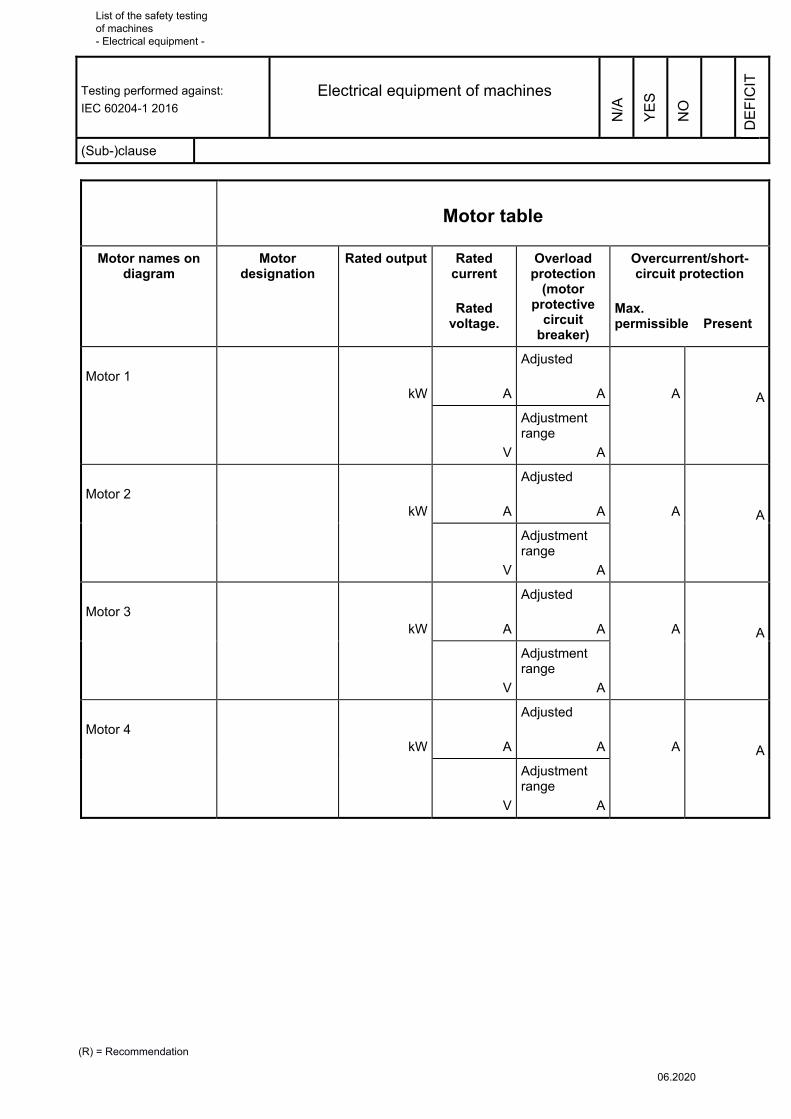
Testing performed against:
IEC 60204-1 2016
Electrical equipment of machines
(Sub-)clause
(R) = Recommendation
DE
FIC
IT
N/A
YE
S
NO
Motor table
Motor names on diagram
Motor designation
Rated output Rated current
Rated
voltage.
Overload protection
(motor protective
circuit breaker)
Overcurrent/short-circuit protection
Max. permissible Present
Motor 1
kW
A
Adjusted
A
A
A
V
Adjustment range
A
Motor 2
kW
A
Adjusted
A
A
A
V
Adjustment range
A
Motor 3
kW
A
Adjusted
A
A
A
V
Adjustment range
A
Motor 4
kW
A
Adjusted
A
A
A
V
Adjustment range
A
List of the safety testing of machines - Electrical equipment -
06.2020

Testing performed against:
IEC 60204-1 2016
Electrical equipment of machines
(Sub-)clause:
(R) = Recommendation
DE
FIC
IT
NO
YE
S
N/A
5.19 Overload and overcurrent (short-circuit) protection
5.19.1 Motors
7.3.1
7.3.2
1. Motors with ratings of > 0.5 kW have overload protection, detection, and interruption of all live conductors except the neutral conductor
�
7.3.1 2. Where interruption is unacceptable, a warning signal is issued �
7.2.9 3. Motor overload protection (bimetal switch for motor protection), correctly adjusted (see motor table, Section 4.18) Type of overload protection:
�
7.3.1 4. Restarting following tripping prevented (where necessary) �
7.3.1 5. Overload protection by means of over-temperature protection or similar (possibly with additional protection for blocked rotor or single-phasing)
�
7.2.8 6. Short-circuit protection (back-up fuse) of motor protective switches, bimetal relays, MCBs is assured (statement on rating plate and in lists)
�
7.4 7. Protection against abnormal temperature provided �
7.2.7 8. Transformers possess suitable overcurrent protection �
5.19.2 Circuits (conductors) – current-carrying capacity
12.4 7.1
1. Conductors rated for the highest possible current under steady-state conditions; see IEC 60204-1, Table 6 and Annex D
�
12.4 7.2 6.3.1
2. Conductors adequately protected against overcurrent (short-circuit, for example in the event of an insulation fault) by suitable protective equipment; see IEC 60204-1, Annex D
�
7.2.8 No overcurrent protection on the load side of the main conductor Short-circuit hazard prevented by the following measures:
- Current-carrying capacity sufficient for the load, and
- Supply conductor not longer than 3 m, and
- Protected against external influences by an enclosure or cable duct
�
List of the safety testing of machines - Electrical equipment -
06.2020

Testing performed against:
IEC 60204-1 2016
Electrical equipment of machines
(Sub-)clause:
(R) = Recommendation
DE
FIC
IT
NO
YE
S
N/A
5.20 Accessories and lighting
5.20.1 Lighting
15.2.1 1. Incorporated into the protective measures by: �
2. Protective conductor connection
3. Total insulation
15.2.3 15.2.2
7.2.6
4. Dedicated overcurrent protection of all non-earthed conductors �
15.2.2 5. Rated voltage below 50 V (R), max. 250 V �
15.2.2 6. Supply by a dedicated transformer with separate windings and overcurrent protection on the secondary side
15.2.2 7. Supply from a circuit of the electrical equipment of the machine
15.2.2 8. Supply from a power supply unit fitted with an isolating transformer (in accordance with IEC 61558-2-6)
15.2.2 9. Transformer connected to the:
Line side of the supply disconnecting device
Load side of the supply disconnecting device
For other alternatives and requirements, see IEC 60204-1, Sub-clause 15.2.2
15.2.4 10. Adjustable lighting fittings: Suitable for workshop use/the ambient conditions
�
15.2.4 11. Lampholders constructed of an insulating material and preventing unintentional contact
�
15.2.4 12. Reflector not supported by the lampholder �
15.2.1 13. On/Off switch not incorporated into the lampholder or connecting cord
�
15.2.1 14. Stroboscopic effects from the lighting are avoided �
5.20.2 Socket outlets for accessory equipment
15.1 1. Socket outlets up to 16 A compliant if possible with IEC 60309-1; if not, marked with the voltage and current values
�
15.1 2. Protected against overcurrent and overload separately from other circuits
�
15.1 3. Protective conductor connecting point provided for accessories �
15.1
Table A.1 / A.2
4. Where the supply is disconnected automatically, the disconnection times satisfy those in Table A.1/A.2
�
15.1 5. Use of an RCD with a rated operating current of ≤ 30 mA (on circuits with a current rating of ≤ 20 A)
�
List of the safety testing of machines - Electrical equipment -
06.2020
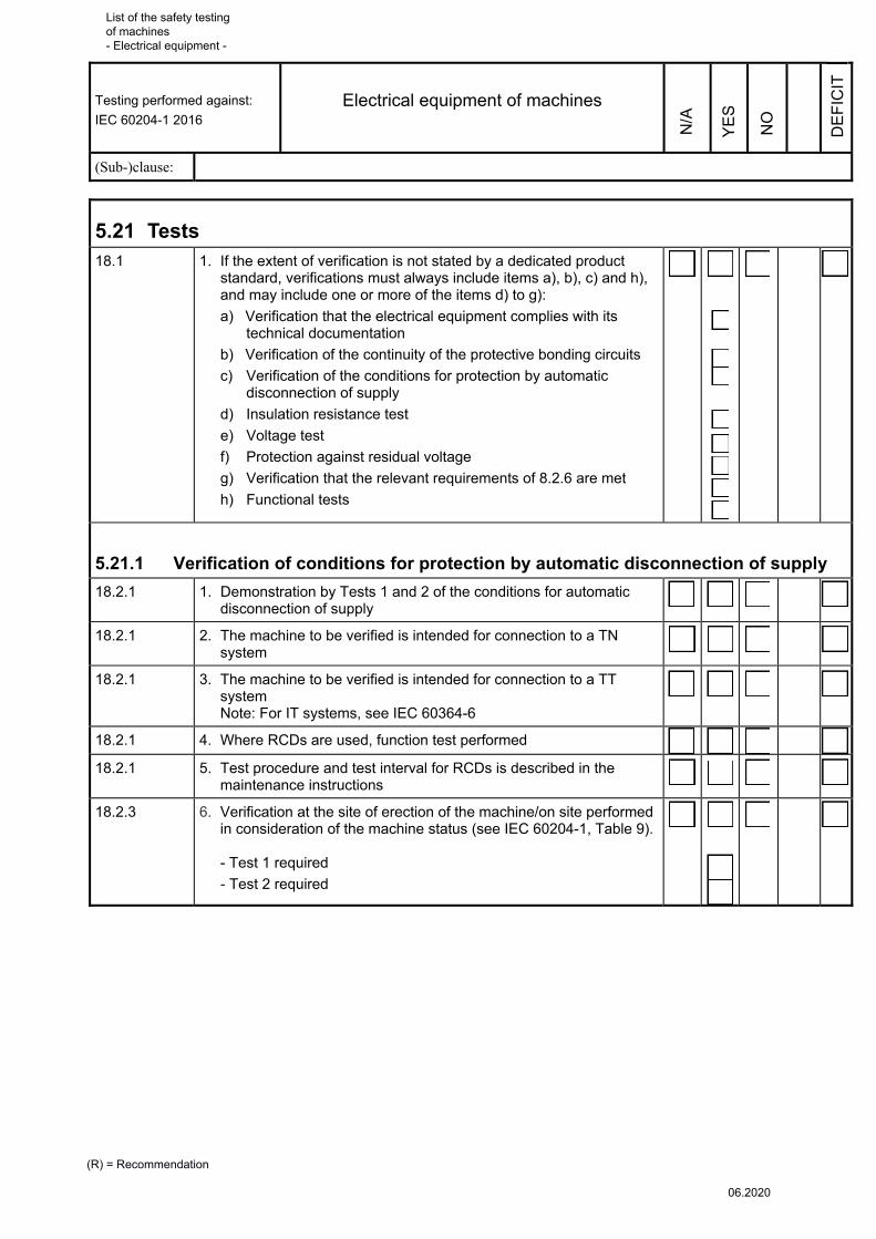
Testing performed against:
IEC 60204-1 2016
Electrical equipment of machines
(Sub-)clause:
(R) = Recommendation
DE
FIC
IT
NO
YE
S
N/A
5.21 Tests 18.1 1. If the extent of verification is not stated by a dedicated product
standard, verifications must always include items a), b), c) and h), and may include one or more of the items d) to g):
a) Verification that the electrical equipment complies with its technical documentation
b) Verification of the continuity of the protective bonding circuits
c) Verification of the conditions for protection by automatic disconnection of supply
d) Insulation resistance test
e) Voltage test
f) Protection against residual voltage
g) Verification that the relevant requirements of 8.2.6 are met
h) Functional tests
�
5.21.1 Verification of conditions for protection by automatic disconnection of supply
18.2.1 1. Demonstration by Tests 1 and 2 of the conditions for automatic disconnection of supply
�
18.2.1 2. The machine to be verified is intended for connection to a TN system
�
18.2.1 3. The machine to be verified is intended for connection to a TT system Note: For IT systems, see IEC 60364-6
�
18.2.1 4. Where RCDs are used, function test performed �
18.2.1 5. Test procedure and test interval for RCDs is described in the maintenance instructions
�
18.2.3 6. Verification at the site of erection of the machine/on site performed in consideration of the machine status (see IEC 60204-1, Table 9). - Test 1 required
- Test 2 required
�
List of the safety testing of machines - Electrical equipment -
06.2020

Testing performed against:
IEC 60204-1 2016
Electrical equipment of machines
(Sub-)clause:
(R) = Recommendation
DE
FIC
IT
NO
YE
S
N/A
5.21.1.1 Test 1: Continuity of the protective
18.1 b) 1. Testing is performed for each protective bonding circuit of a machine
�
18.2.2 Measurement of the continuity of the protective bonding circuit: - Between the PE terminal and relevant points in the protective bonding circuit - With a current between at least 0.2 A and 10 A (higher currents are to be preferred, as they increase the accuracy of the test results) - From an electrically separated supply source, e.g. SELV (where possible, not PELV) with a maximum no-load voltage of 24 V AC or DC
The resistance measured is within the range expected for the length, cross-sectional area and material of the protective conductor(s) Where a PELV supply is used, earthing may have to be disconnected (for the duration of measurement only)
Testing point
Cross-sectional
area [mm2]
Length [m]
Resistance [Ω]
1. Switchgear cabinet
2. Mounting plate
3. Switchgear cabinet doors/lids with electrical equipment
4. Control panels (including anodized)
5. Motors, valves
6. Body of the machine
7. Appliance couplers, limit switches, foot-operated
switches
8. Metal hoses, metal cable glands
9. Manually operated controls (pendant push-buttons,
swivel arms)
10. Withdrawable units
11. Parts which are removed and held in the hand for the
purpose of adjustment/maintenance
12. .....................................................................................
13. .....................................................................................
14. Requirements concerning the resistance of the
protective conductor are satisfied in all testing points �
List of the safety testing of machines - Electrical equipment -
06.2020

Testing performed against:
IEC 60204-1 2016
Electrical equipment of machines
(Sub-)clause:
(R) = Recommendation
DE
FIC
IT
NO
YE
S
N/A
5.21.1.2 Test 2: Fault loop impedance and suitability of the overcurrent protective device
18.2.3 1. Power supply and external protective conductor securely connected (visual inspection)
�
18.2.3 2. The conditions for protection by automatic disconnection of the power supply are verified by:
a) Verification of the fault loop impedance by:
- Compliance with IEC 60204-1, Table 10 (TN system) or
- Measurement in compliance with A.1.4.2 (TN systems), or
- Measurement in compliance with A.2.4 (TT systems), or
- Calculation AND
b) Verification of the characteristics and settings of the overcurrent protective devices (Annex A). The PDS manufacturer's and protective device manufacturer's instructions are observed
�
18.2.4 Table 10
3. Fault loop impedance – IEC 60204-1, Table 10:
Table 10 lists examples of maximum cable/conductor lengths for protective devices and their loads in TN systems.
Requirements concerning the fault loop impedance for TN systems can be considered met when the maximum lengths stated in Table 10 are not exceeded and the assumptions stated there are observed.
Deviation from these assumptions may necessitate complete calculation or measurement of the fault loop impedance.
Circuits affected are:
………………………………………………………………………
………………………………………………………………………
�
List of the safety testing of machines - Electrical equipment -
06.2020
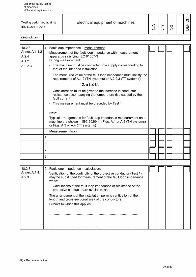
Testing performed against:
IEC 60204-1 2016
Electrical equipment of machines
(Sub-)clause:
(R) = Recommendation
DE
FIC
IT
NO
YE
S
N/A
18.2.3 Annex A.1.4.2
A.2.4
A.1.2
A.2.2.3
4. Fault loop impedance – measurement:
Measurement of the fault loop impedance with measurement apparatus satisfying IEC 61557-3 During measurement:
- The machine must be connected to a supply corresponding to that of the intended installation
- The measured value of the fault loop impedance must satisfy the requirements of A.1.2 (TN systems) or A.2.2.3 (TT systems):
Zs x Ia ≤ U0
- Consideration must be given to the increase in conductor resistance accompanying the temperature rise caused by the fault current
- This measurement must be preceded by Test 1
Note:
Typical arrangements for fault loop impedance measurement on a machine are shown in IEC 60204-1, Figs. A.1 or A.2 (TN systems) or Figs. A.3 or A.4 (TT systems)
�
Measurement loop �
5. �
6. �
7. �
8. �
18.2.3 Annex A.1.4.1
A.2.3
9. Fault loop impedance – calculation:
Verification of the continuity of the protective conductor (Test 1) may be substituted for measurement of the fault loop impedance when:
- Calculations of the fault loop impedance or resistance of the protective conductor are available, and
The arrangement of the installation permits verification of the length and cross-sectional area of the conductors
Circuits to which this applies:
………………………………………………………………………
………………………………………………………………………
�
List of the safety testing of machines - Electrical equipment -
06.2020
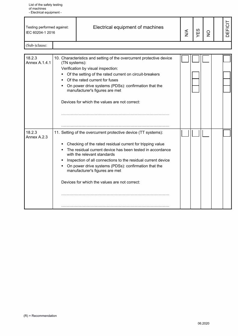
Testing performed against:
IEC 60204-1 2016
Electrical equipment of machines
(Sub-)clause:
(R) = Recommendation
DE
FIC
IT
NO
YE
S
N/A
18.2.3 Annex A.1.4.1
10. Characteristics and setting of the overcurrent protective device (TN systems):
Verification by visual inspection:
Of the setting of the rated current on circuit-breakers
Of the rated current for fuses
On power drive systems (PDSs): confirmation that the manufacturer's figures are met
Devices for which the values are not correct:
………………………………………………………………………
………………………………………………………………………
�
�
�
�
18.2.3 Annex A.2.3
11. Setting of the overcurrent protective device (TT systems):
Checking of the rated residual current for tripping value
The residual current device has been tested in accordance with the relevant standards
Inspection of all connections to the residual current device
On power drive systems (PDSs): confirmation that the manufacturer's figures are met
Devices for which the values are not correct:
………………………………………………………………………
………………………………………………………………………
�
List of the safety testing of machines - Electrical equipment -
06.2020
Testing performed against:
IEC 60204-1 2016
Electrical equipment of machines
(Sub-)clause:
(R) = Recommendation
DE
FIC
IT
NO
YE
S
N/A
5.21.2 Insulation resistance test
1. Preliminary test:
Verification that no connection exists in the power circuit between the protective bonding circuit and the neutral conductor
�
18.3 2. Testing of the insulation resistance by means of measurement apparatus complying with the IEC 61557 series of standards
Measurement is performed:
- Between the power circuit conductors (including the neutral conductor) and the protective bonding circuit
- At a voltage of 500 V DC
- The measured insulation resistance must not be < 1 MΩ
Measured value: ……………….……
Exception: For certain parts of the electrical equipment (e.g. busbars, conductor bar/wire systems, slip-ring systems), a lower value is permitted, but not < 50 kΩ
Note: Where surge protection devices are present which are expected to trip during the test, it is permissible for: - The devices concerned to be disconnected, or - The test voltage to be reduced to a value lower than the voltage protection level of the surge protection devices, but not lower than the upper limit of the supply (phase to neutral) voltage
�
5.21.3 Voltage test
1. Preliminary test:
Verification that no connection exists in the power circuit between the protective bonding circuit and the neutral conductor
�
18.4 2. Use of test equipment in accordance with IEC 61180 for the voltage test
- Rated frequency of the test voltage: 50 Hz or 60 Hz
- Maximum test voltage: twice the rated supply voltage of the equipment or 1 000 V, whichever is the greater
- Application of the maximum test voltage between the power circuit conductors (including the neutral conductor) and the protective bonding circuit for approximately 1 s
- The requirements are satisfied if no disruptive discharge occurs
Note: Assemblies and devices which are not rated to withstand this test voltage or which have already been subject to voltage testing in compliance with their product standards were disconnected prior to the test
�
List of the safety testing of machines - Electrical equipment -
06.2020

Testing performed against:
IEC 60204-1 2016
Electrical equipment of machines
(Sub-)clause:
(R) = Recommendation
DE
FIC
IT
NO
YE
S
N/A
5.22 Other verification 18.1 1. The electrical equipment complies with its technical documentation �
18.5 2. Protection against residual voltage complies with IEC 60204-1, Sub-clause 6.2.4
�
18.6 3. Functional tests
Refer also to Section 5.11, Stop functions, and Section 5.12, Control functions
Refer to the separate checklist for control systems if applicable
�
18.6 4. Functional tests of the electrical equipment passed �
7.10
IEC 61439-1
5. Short-circuit current rating determined by:
- Application of design rules
- Calculation
- Testing
�
6 Information for use and technical documentation
6.1 Instruction handbook Machinery Directive, Annex I, Section 1.7.4
1. Information for use in the language of the Member State �
Machinery Directive, Annex I, Section 1.7.4
2. Original information for use and translation in the language of the country of use are available
�
Machinery Directive, Annex I, Section 1.7.4
3. Maintenance instructions for specialised personnel; Community language understood by the specialised personnel
�
17.1 4. The information for use contains instructions on identification, transport, installation, use, maintenance, decommissioning and disposal, specifically for equipment and circuits with a protective function
- Emergency Switching Off/Stop category
- Moving guard
- Set-up mode
- Manual mode
-
-
�
6.2 Information on the electrical equipment
6.2.1 General 17.1 1. Information provided for the purposes of identification, transport,
installation, use, maintenance, decommissioning and disposal �
List of the safety testing of machines - Electrical equipment -
06.2020

Testing performed against:
IEC 60204-1 2016
Electrical equipment of machines
(Sub-)clause:
(R) = Recommendation
DE
FIC
IT
NO
YE
S
N/A
17.2 a) 2. Where more than one document is provided, a main document for
the electrical equipment as a whole, listing the complementary documents associated with the electrical equipment, is provided
�
6.2.2 Information on installing and mounting The information on installing and mounting addresses the following
points:
17.2 c) 1. Information on installing and mounting including a description of the electrical equipment's connection to the power supply
�
17.2 c) 2. The short-circuit current rating of the electrical equipment for each incoming power supply
�
17.2 c) 3. The rated voltage, number of lines, frequency, type of distribution system and full-load current for each incoming power supply
�
17.2 c) 4. Any additional requirements of the electrical supply/supplies (e.g. maximum supply source impedance, leakage current);
�
17.2 c) 5. Space required for removal or servicing of the electrical equipment �
17.2 c) 6. Installation requirements to prevent impairment of cooling �
17.2 c) 7. Environmental limitations (for example lighting, vibration, EMC environment, atmospheric contaminants), where required
�
17.2 c) 8. Functional limitations (for example peak starting currents and permitted voltage drops), where required
�
17.2 c) 9. Precautions to be taken for the installation of the electrical equipment relevant to electromagnetic compatibility
�
17.2 d) 10. Where extraneous parts can be touched simultaneously with the machine, instructions for their connection to the protective conductor; examples of such parts are:
Metallic pipes
Fences
Ladders
Handrails
�
6.2.3 Information on function and operation 17.2 e) Information should provide the following content as applicable: �
17.2 e) 1. An overview of the structure of the electrical equipment (for example by structure diagram or overview drawing)
�
17.2 e) 2. Procedures for programming or configuring, where necessary for the intended use
�
17.2 e) 3. Procedures for restarting following an unexpected stop �
17.2 e) 4. Sequence of operation �
6.2.4 Information on maintenance
17.2 f) 1. Frequency and method of functional testing �
List of the safety testing of machines - Electrical equipment -
06.2020

Testing performed against:
IEC 60204-1 2016
Electrical equipment of machines
(Sub-)clause:
(R) = Recommendation
DE
FIC
IT
NO
YE
S
N/A
17.2 f) 2. Instructions on the procedures for safe maintenance and, where necessary, information on suspending safety functions and/or protective measures (see 9.3.6)
�
17.2 f) 3. Guidance on adjustment, repair, and the frequency and method of preventive maintenance
�
17.2 f) 4. Details of the interconnections of the electrical components subject to replacement (for example by circuit diagrams and/or connection tables)
�
17.2 f) 5. Information on any special devices or tools required �
17.2 f) 6. Information on spare parts �
17.2 f) 7. Information on possible residual risks and on whether any particular training is required; specification of personal protective equipment, where required
�
17.2 f) 8. Where applicable, instructions to restrict availability of keys or tools to electrically skilled or instructed persons
�
17.2 f) 9. Settings (DIP switches, programmable parameter values, etc.) �
17.2 f) 10. Information for validation of safety-related control functions following repair or modification, and for periodic testing where necessary
�
17.2 g) 11. Where required, information on handling, transportation and storage (for example dimensions, weight, environmental conditions, possible ageing constraints)
�
17.2 h) 12. Information on proper disassembly and handling of components (for example for recycling or disposal)
�
List of the safety testing of machines - Electrical equipment -
06.2020

Testing performed against:
IEC 60204-1 2016
Electrical equipment of machines
(Sub-)clause:
(R) = Recommendation
DE
FIC
IT
NO
YE
S
N/A
6.3 Information to be provided, circuit diagrams, parts lists 17.2 1. Circuit diagrams
....................................................................................................
....................................................................................................
....................................................................................................
....................................................................................................
....................................................................................................
2. Parts lists/component lists
....................................................................................................
....................................................................................................
....................................................................................................
....................................................................................................
....................................................................................................
For each part, the parts list contains the
- Equipment identifier - Type designation - Supplier/procurement source - Characteristics - Quantity
3. Drawings
....................................................................................................
....................................................................................................
....................................................................................................
....................................................................................................
....................................................................................................
4. Instruction/maintenance handbook
....................................................................................................
....................................................................................................
....................................................................................................
....................................................................................................
....................................................................................................
List of the safety testing of machines - Electrical equipment -
06.2020