3 description of the proposed developement · 3.2.3.1 caustic strength the concentration of caustic...
TRANSCRIPT
Expansion of BRDA and Increase in Alumina Production Capacity at Aughinish Alumina Ltd
3 DESCRIPTION OF THE PROPOSED DEVELOPEMENT
3.1 INTRODUCTION The EIS covers the proposed raising, extension and associated modifications to the Bauxite Residue Disposal Area and also an increase in alumina production to align production capacity. with the permitted Integrated Pollution Control Licence (1.95 mtpa). The description of the proposed development details the following:
.
.
.
0 . .
. Upgrade of the Water Management System, the Storm Water Pond and the Liquid Waste Pond.
. Realignment of part of the Flood Tidal Defence Berm (FTDB) adjacent to Robertstown River.
3.2
Retention of the existing alumina production capacity of 1.6 mtpa (2004) with associated emissions within permitted Integrated Pollution Control Licence limits.
Increase in existing alumina production capacity (2004) to 1.95 mtpa (2010) with associated emissions to remain within permitted Integrated Pollution Control Licence limits.
Increase in the height of the existing Phase 1 BRDA from Stage 7 perimeter (central elevation of 27.5m AMSL) to Stage 10 perimeter (central elevation of 32m AMSL).
Provision of a Phase 2 BRDA as an extension to the existing Phase 1 BRDA.
Relocation of the Salt Cake Disposal Area from the original BRDA to the composite lined area of the Phase 1 Extension BRDA.
INCREASE IN PLANT PRODUCTION CAPACITY
3.2.1 General In May 1989, AAL was granted planning permission to upgrade the alumina plant production capacity to 1.0 mtpa. This planning permission also related to other environmental conditions previously imposed, such as emission rates and concentrations. By 1992, production capacity had already reached this level. In 1994 the EPA assumed responsibility for the environmental licensing and performance of activities listed in the EPA Act 1992. In 1998 AAL received an IPC licence that permitted production of approximately 1.75 mtpa. Current production of alumina is approximately 1.6 mtpa. In 2004, the EPA issued a reviewed IPC licence that permitted production of approximately 1.95 mtpa alumina. In line with industry developments worldwide, AAL are now seeking to raise the processing capability of the plant to 1.95 mtpa.
3.2.2 Increase in Plant Production Capacity to 1.6 mtpa The plant production rate has increased gradually from 1 to 1.6 mtpa in annual increments of 3-4% per year through increased efficiencies. The principal enabling factors are outlined below.
Caustic concentration in recirculating plant liquor determines the alumina production capacity of each m’ of liquor processed. Improved materials specification and monitoring to minimize caustic corrosion has enabled higher caustic strength within digestion while improved liquor purity control and size control within precipitation has maintained product quality at the target level. Over the past 10 years, the strength has been gradually increased from 215 to 255 gpl Na2C03 such that the production yield has increased from 63 kg/m3 to 82 kg/m3 which represents a 30% increase in production.
Re-circulatinn liauor flow is the other main factor determining production rate. Over the past 10 years, de-bottlenecking of pipes and pumps linking digestion, the mud circuit, precipitation and calcination
Environmental Impact Statement
- .
20
.- - Volume 2
For
insp
ectio
n pur
pose
s only
.
Conse
nt of
copy
right
owne
r req
uired
for a
ny ot
her u
se.
EPA Export 25-07-2013:17:27:39
Expansion of BRDA’and Increase in Alumina Production Capacity at Aughinish Alumina Ltd
has enabled the plant flow to be increased from 1900 m3/hr to 2400 m3/hr which represents a further 25% increase in production capacity.
To handle the extra red mud residue qenerated, the mud filtration and pumping unit was upgraded by 60% by speeding up of the existing six drum filters and three high pressure disposal pumps and through the installation of two additional drum filters and one additional pump. (Planning Permission No. 1946/96 of 1996)
The Bauxite Residue Disposal Area was also increased in size by some 45% (Phase 1 Extension) during this period. (Planning Permission No. 1133/93 of 1993). An EIS for this extension was prepared by Ove Arup and Partners in 1993.
To handle the extra alumina hydrate Product and seed recirculatinq in the precipitation circuit, two alumina hydrate seed filters (new building) and three sets of hydrate classification cyclones (plant and machinery within existing building) were added at the seed classification section of precipitation. (Planning Permission No. 737/95 of 1995 applies for the new building).
The extra capacitv in Calcination was achieved through a series of duct and cyclone size increases and through the provision of an additional air blower per Calciner (new machinery within an existing building). This increased individual Calciner capacity by 28% from 57 tph to 73 tph alumina. Additional Calcination capacity was also realized by investing in Calciner reliability and thereby increasing its on- line availability.
To handle the extra alumin’a shipping requirement, an alumina conveyor section feeding the inner berth from the main alumina conveyor and a new inner berth alumina ship loader were constructed. (Planning Permission No. 839/95 of 1995).
To accommodate this at least cost and without increasing employee numbers, the plant invested in increased on-line instrumentation and automation and applied advanced control techniques to optimise process conditions.
3.2.3 Current Production Constraints
Baseline production of alumina is approximately 1.6 mtpa. However, there are a number of constraints in the production process that restrict any increase in production. The current constraints on the plant production capacity are as fotlows:
3.2.3.1 Caustic strength
The concentration of caustic soda in the plant recirculating liquor stream determines its alumina- carrying capacity. Caustic strength at AAL is currently constrained by the Sodium Oxalate concentration in recirculating liquor. AAL operates what is termed an ‘oxalate-free’ precipitation circuit. This facilitates alumina size and strength control. This oxalate free mode is achieved by continuously removing sodium oxalate via deep evaporation of a process liquor side-stream. As caustic concentration increases, the solubility of sodium oxalate in caustic reduces and lowers the target sodium oxalate concentration required to prevent sodium oxalate auto-nucleation in the alumina hydrate precipitation circuit. This sodium oxalate removal capacity bottleneck limits caustic strength and thus alumina production rate.
3.2.3.2 Alumina Quality Cbntrol
As caustic and alumina concentrations increase in digestion, so do the concentrations of certain impurities such as Fe203 and SiO*. Also, as caustic strength increases, the efficiency of fines agglomeration within precipitation reduces, causing a weakening of product alumina. The levels of these impurities and the strength of alumina are commercially established and alumina quality must be compatible to be marketable in the industry.
Environmental Impact Statement 21 Volume 2
For
insp
ectio
n pur
pose
s only
.
Conse
nt of
copy
right
owne
r req
uired
for a
ny ot
her u
se.
EPA Export 25-07-2013:17:27:39
Expansion of BRDA and Increase in Alumina Production Capacity at Aughinish Alumina Ltd
3.2.4 Increase in Plant Production Capacity to 1.95 mtpa
Two main process will be implemented to achieve an increased production capacity:
. Sweetening - this involves optimising the chemical extraction and recovery process of alumina from bauxite and
. De-bottlenecking - this involves increasing the speed and/or rates at which raw materials, process slurries/fluids and product material are transferred within the plant.
Increasing the rated processing capability of the plant will involve using
. existing permitted plant and machinery within the alumina process and
. plant and machinery currently being installed or constructed for which Aughinish Alumina has already obtained planning permission (ref 04/262) from the Planning Authority
Apart from the expansion of the BRDA and associated works, no future works or physical developments are required to be constructed for the proposed increase in production capacity. Planning permission has been obtained for any previous or current works or physical developments . The development will take place totally within the footprint of the existing alumina plant and there will be no physical extension of any site boundaries.
3.2.4.1 Sweetening
Currently, the plant is undergoing a modernisation programme. This includes a process optimisation project featuring a digestion modification, termed ‘Sweetening’, whereby additional bauxite can be processed by utilising waste steam within digestion. During the alumina extraction process, two different types of bauxite are used - Bake and MRN bauxites. The type of alumina in MRN bauxite requires a lower temperature for digestion than the alumina present in Bake bauxite. The MRN bauxite has separate grinding and pre-treatment facilities. Following this treatment, the MRN bauxite slurry will be injected into the flash tank train downstream of the present high temperature digesters. This will yield extra production capacity without requiring additional steam.
The scope of the optimisation project also includes:
. Increased bauxite storage to facilitate better bauxite management and reduce possibility of cross contamination. The average amount of bauxite held on-site will increase from 200,000 to 250,000 tonnes.
. An additional crushed bauxite bin and grinding mill to permit finer bauxite grinding for improved alumina extraction in digestion.
. A process flow stabilization project to provide better use of tank volume to dampen flow surges to precipitation. This will facilitate improved precipitation seeding and temperature control for improved product quality.
e Provision of additional caustic cleaning circuits to ensure that pipe-line capacity is kept close to its design level despite increased scaling rates linked to higher alumina concentrations in circulating plant liquor.
The above optimisation project provides a basis for, raising plant production to ‘I .95 mtpa if cost effective solutions can be found for the two key production-limiting problems - caustic strength and alumina quality.
Environmental Impact Statement 22 Volume 2
For
insp
ectio
n pur
pose
s only
.
Conse
nt of
copy
right
owne
r req
uired
for a
ny ot
her u
se.
EPA Export 25-07-2013:17:27:39
.’
Expansion of BRDA &nd Increase in Alumina Production Capacity at Aughinish Alumina Ltd
3.2.4.2 De Bottlenecking
In general, a higher production rate would invariably require a number of smaller internal processing bottlenecks to be removed from existing plant and machinery within existing buildings and bunded areas and will be achieved by replacement or addition of the following:
. Some larger motors to handle the slightly increased power demand
. Some larger pipes to process the higher product and residue production rates
. Addition of some extra heat exchange area to compensate for the invariably higher scaling rate
. Extra seed classification capacity in the existing precipitation circuit tankage
De-bottlenecking will involve increasing the speed and/or rates at which raw materials, process slurries/fluids and product material are transferred within the plant. These increases will facilitate the increased production rate of alumina brought about by the introduction of the ‘sweetening’ procedure in the plant. De-bottlenecking procedures will also involve retrofitting higher throughput plant and machinery within some existing buildings, and will include the following:
.
.
.
.
.
.
.
.
.
.
.
.
.
The rate and quantity of bauxite conveyed from the bauxite storage sheds to the crushing mills will be increased by the addition of a new bauxite conveyor extension.
A new bauxite transfer pump to supply additional ground bauxite to the Sweetening point within Digestion
New seed filters to increase seeding rate while reducing spent liquor recirculation
New cooling stages and cooling tower in the precipitation chains
Calciner internals upgrade (larger ducts, modified Electra Static Precipitators)
Additional on-line analysers to facilitate process optimization (Alumina/Caustic (A/C) control in Digestion, interface & clarity in Mud Circuit, Particle Size Distribution in Precipitation)
New pumps to pump Filtrate through Vacuum Flash
The recirculating liquor flow rate and caustic strength will be increased in order to increase liquor productivity and plant production rate.
Increasing the removal of impurities from the circulating caustic by improved cooling and seed evaporation of the stream of caustic being filtered of impurities.
Increased cooling (with plate coolers) of the liquor within two of the existing precipitators to lower A/C ratio
Increased pumping capacity within the existing plant for pumping filtrate
Overhauling all machinery within the existing Fine Seed Filtration building. There will be no change to the exterior of the building or creation of new floor or partitioning of the space within the building.
Operation of new wash cyclones within the existing building
The footprint size and shape of the plant will not be altered either in plan nor in vertical height by these modifications to existing plant and machinery.
Environmental Impact Statement 23 Volume 2
For
insp
ectio
n pur
pose
s only
.
Conse
nt of
copy
right
owne
r req
uired
for a
ny ot
her u
se.
EPA Export 25-07-2013:17:27:39
Expansion of BRDA and Increase in Alumina Production Capacity at Aughinish Alumina Ltd
3.3 EXTENSION AND MODIFICATION OF BRDA
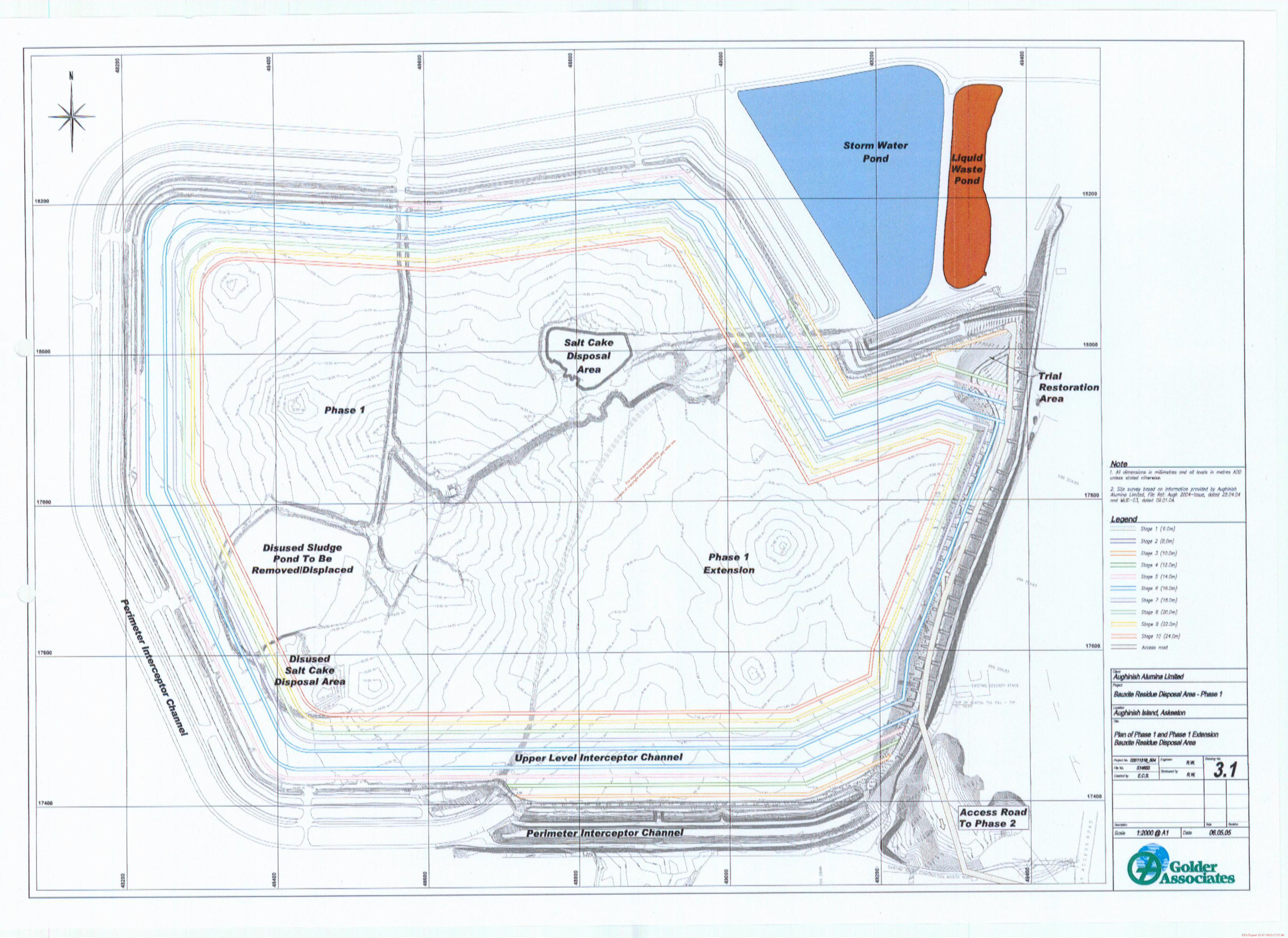
3.3.1 Phase 1 Modifications
Currently, the original BRDA is at Stage 5, while the Phase 1 extension is at Stage 2 (Stage 3 is under construction). The entire Phase 1 BRDA is permitted to go to Stage 7, which will have a central elevation of 27.5m AMSL. The following sections summarise the modifications that will be carried out to increase the storage capacity of the Phase 1 BRDA. It is proposed that Stages 8, 9 and 10 will be added, resulting in a maximum central height of 32m AMSL for the entire Phase 1. Modifications will also include construction of an upper level interceptor channel, decommissioning of the disused sludge pond and relocation of the salt cake disposal area.
3.3.1 .I Perimeter Raises
The method of raising the perimeter stack wall retaining the red mud is by the ‘upstream method’ where successive stack walls are constructed on previously deposited red mud, as described in Section 2.4.1. The red mud is allowed to mature for as long as possible (approximately 3 months) prior to placing the next layer. The success of this method of stack raising is dependent on the design of the facility and its ongoing performance. The performance of the facility will be monitored using a comprehensive geotechnical monitoring system within the stack wall together with an intrusive site investigation carried out prior to any future raising.
By incorporating an upper level interceptor channel at Stage 6 (as described in Section 3.3.1.2), the overall slope of the perimeter stack wall from Stage 1 to IO will be reduced, thus making the perimeter more stable. An overall view of the Phase 1 BRDA, showing the crest of each raise up to Stage IO and a typical cross section through the Phase 1 stack wall are presented in Figure 3.1 and Figure 3.2 respectively.
The perimeter raises will be constructed of rockfill placed over either a layer of process sand or a geotextile liner fabric. The sand is primarily used in low spots but also, as with the geotextile, prevents the imported rockfill punching through the red mud.
A filtering system will be required upstream of the rockfill embankment walls to prevent the migration of particles of red mud as a result of water erosion (Figure 3.2). The filter system will be required to retain the fine mud particles but have sufficient permeability to allow the passage of water through the stack wall. The filter system will be either constructed from a combination of processed rockfill and sand or processed rockfill and a geotextile material. A series of trials will be undertaken to optimise the method and materials to be employed, prior to construction.
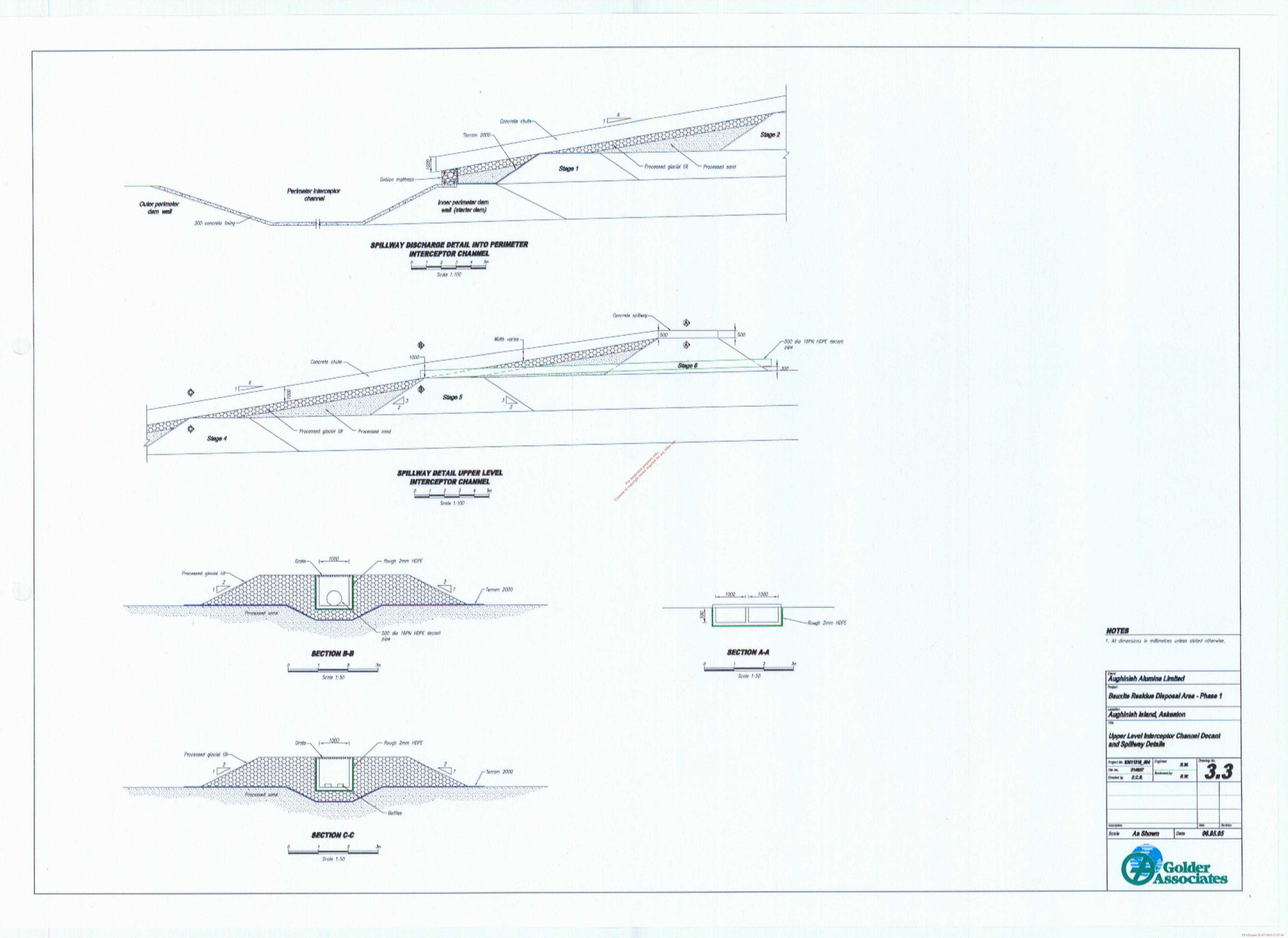
3.3.1.2 Upper Level Interceptor Channel
The upper level interceptor channel will be installed when the perimeter stack wall is raised to an elevation of 16mAMSL (Stage 6) and the red mud is at a maximum elevation of 14mAMSL at the stack wall. The width of the channel will be 20m at the top, 14m at the base and 2m in depth.
The channel will collect surface runoff from the exposed red mud at higher elevations from Stage 6 to Stage 10, rather than allowing the water to cascade and erode its way down to the perimeter interceptor channel. It will also allow the outer slopes of the first 6 stage raises to be rehabilitated during the life of the facility.
The upstream face of the outer perimeter Stage 6 stack wall of the interceptor channel will be lined with a High Density Poly Ethylene geomembrane overlying a geotextile material which overlies processed rockfill. The bulk of the fill forming the wall is random rockfill overlying process sand or directly on the red mud with a geotextile material separating the two materials. Further details are shown in Figure 3.2.
During normal operations, the Phase I upper level interceptor channel will store only a limited volume of water. It will discharge from various points along its alignment into the perimeter interceptor channel
Environmental Impact Statement 24
- Volume 2
For
insp
ectio
n pur
pose
s only
.
Conse
nt of
copy
right
owne
r req
uired
for a
ny ot
her u
se.
EPA Export 25-07-2013:17:27:39
Expansion of BRDA and Increase in Alumina Production Capacity at Aughinish Alumina Ltd
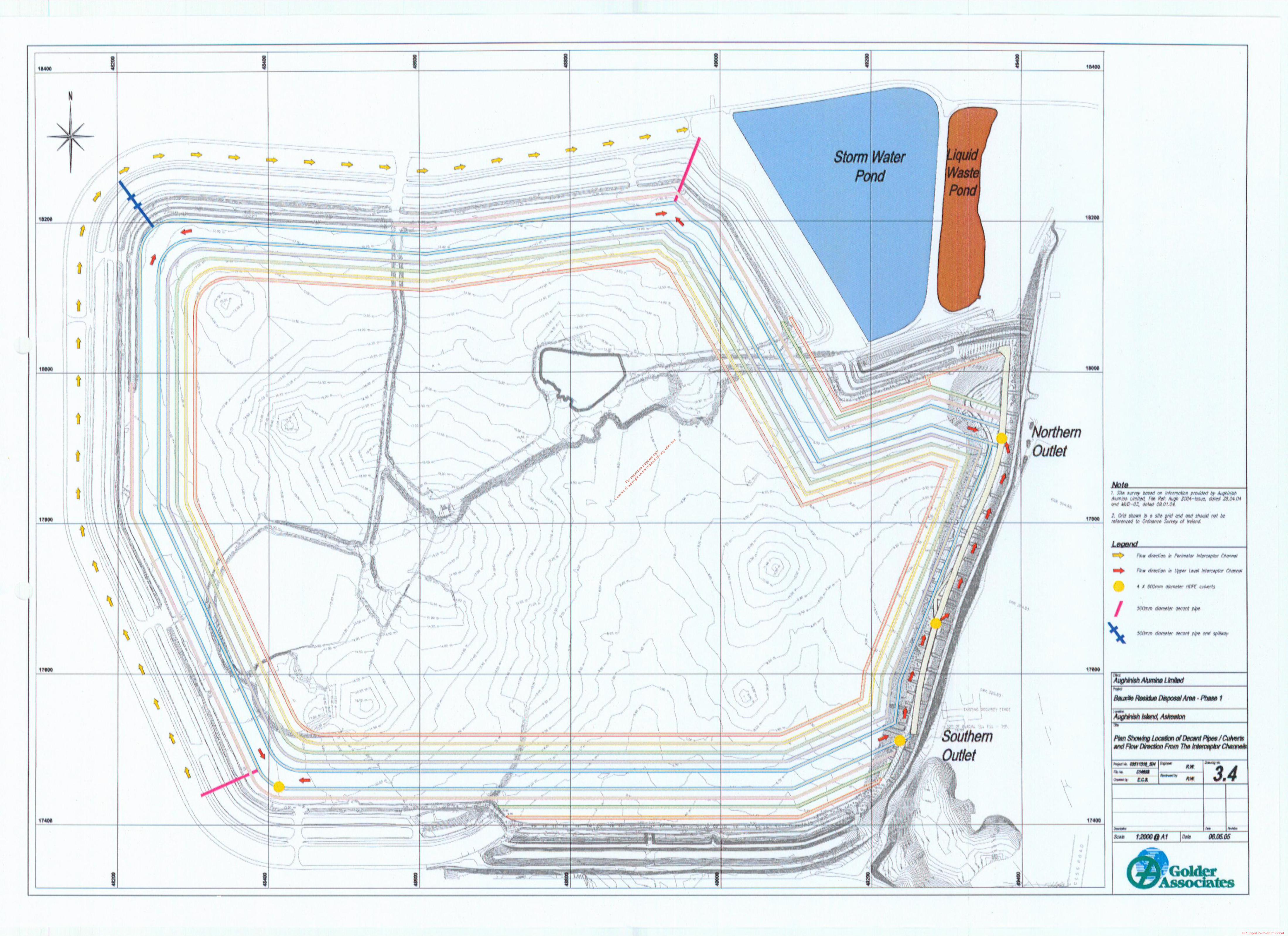
below. At three locations a decant pipe is to be installed near the base of the upper interceptor channel. At one of the locations of the decant pipe, a spillway will also be installed (Figure 3.3). The upper level interceptor channel will also discharge at two ends into the perimeter interceptor channel adjacent to the eastern boundary of the Phase 1 BRDA (Figure 3.4). The northern outlet on the east side is via four culverts and the southern outlet is open.
The filter system on the upstream wall of each raise, including and above Stage 6, will reduce the solids entering the upper level interceptor channel and desludging should not be normally required during operation of the BRDA.
Following completion of the upper level interceptor channel, the visual impact of the BRDA will be improved by covering the stack wall with granular material and top soil,’ which will eventually be revegetated. The rehabilitation of the Stack wall is further discussed in Chapter 11 Landscape and Visual of this volume of the EIS.
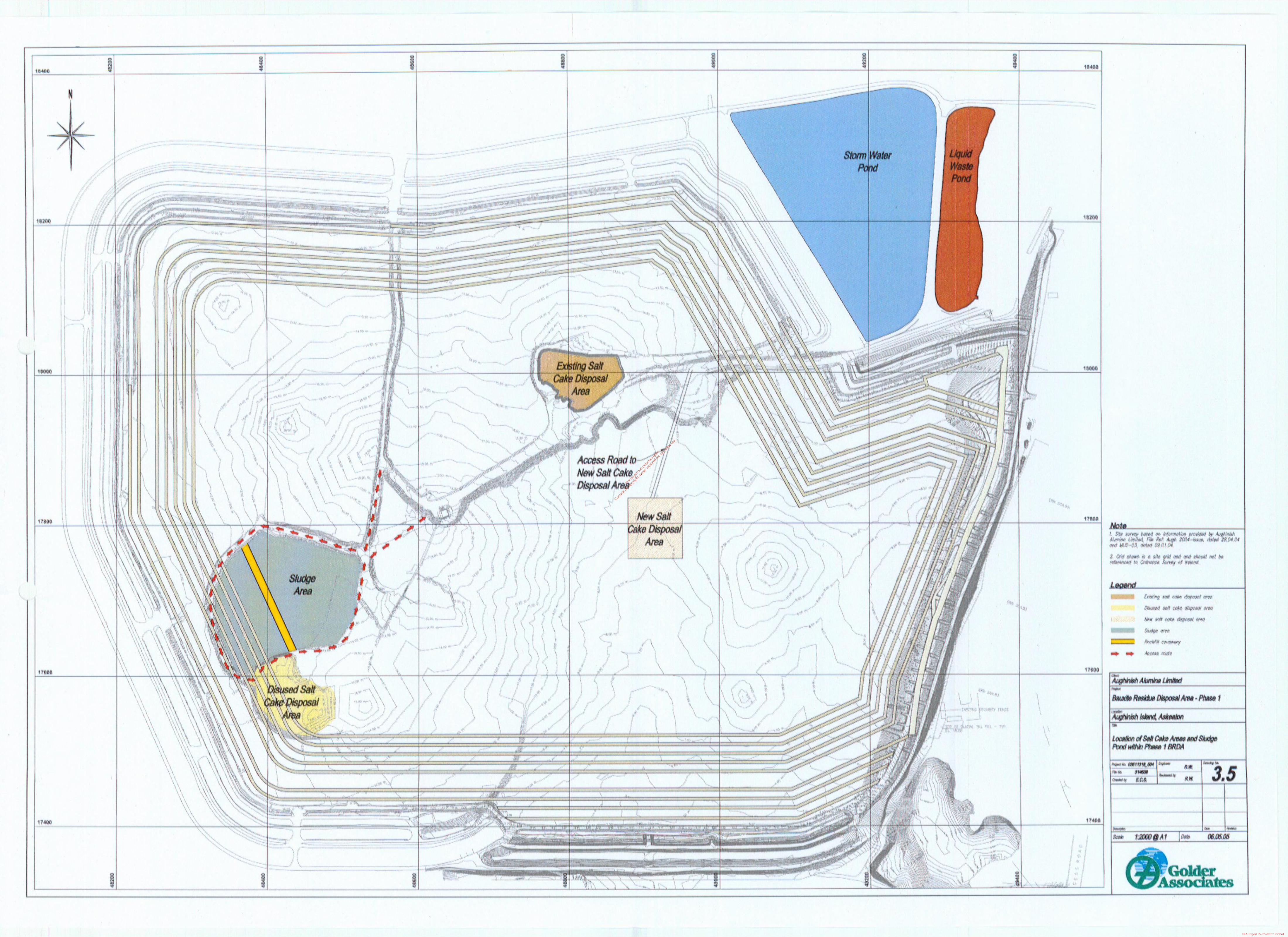
3.3.1.3 Effluent Sludge Pond
The disused sludge pond in the south west sector of the Phase 1 BRDA, which is approximately 2ha in area will be decommissioned as it is situated along the proposed western alignment of the inner wall of Stage 6 and Stages 7 to 10 (Figure 3.5). The sludge in the pond is unsuitable as a foundation material and will need to be removed. The sludges are low-density gel/precipitates with approximately 2% solids. These sludges were derived from the clarification system in the effluent treatment plant before such sludges were absorbed within the process wash plant.
The total volume of sludge stored and the depth to the base of the sludge will be determined prior to any construction taking place in future. The volume is likely to be in excess of 120,000m3 and beneath the stack wall footprint some 40,000m3 of sludge could be present and require removal.
There are a number of methods that could be used to remove the sludges from the pond. The final option must provide a suitable foundation for the stack wall and within the time frame required prior to the construction of Stage 6. Several options have been considered. These include:
. pumping out the sludge and filling the empty pond with a suitable foundation material such as sand or rockfill.
. removing by mechanical methods such as a long reach excavator or dragline excavators and filling the empty pond with suitable foundation material.
. displacement of the sludge over time by red mud.
Whichever option is chosen, the sludges will be treated and disposed of in the BRDA in an environmentally sound manner. Each of the options will take into consideration the following issues;
. access to the sludge pond via a rockfill causeway constructed across it
. removal/displacement of the sludges,
. handling and storage of the sludges once removed,
. backfilling the hollow created by the removal of the sludges.
3.3.1.4 Disused Salt Cake Disposal Area
A disused salt cake disposal area is located to the south of the sludge pond (Figure 3.5). The western side has been backfilled and capped with process sand and the eastern side capped with red mud. This area is on the footprint of the stack raising above Stages 7 and 8. The salt cake is not a suitable
Environmental Impact Statement 25 Volume 2
For
insp
ectio
n pur
pose
s only
.
Conse
nt of
copy
right
owne
r req
uired
for a
ny ot
her u
se.
EPA Export 25-07-2013:17:27:39
Expansion of BRDA and increase in Alumina Production Capa&y at Aughinish Alumina Ltd
foundation material on which to base the stage raises, and will be surveyed prior to construction. Any unsuitable material will be removed and deposited in the current salt cake disposal area.
3.3.1.5 Current and Proposed Salt Cake Disposal Area
Salt cake is currently disposed of in an area located in the north east sector of the original BRDA. (Figure 3.5). It is proposed to continue storing the salt cake in this area and raising the containment walls with process sand in the short term. After Stage 7 is completed, a new salt cake disposal area will be constructed in the Phase 1 extension area, which is composite lined. This will allow the existing salt cake disposal area to be capped initially with process sand and then a minimum of 6m of low permeability red mud, which will reduce the seepage from this area. The proposed disposal area will be founded on at least IOm of red mud over a composite lining and will be isolated from the process sand access road by a IOm long plug of low permeability glacial till. This will inhibit a preferential drainage path provided by the relatively high permeability of the process sand.
The new salt cake disposal area in the Phase I extension area will be used during the life of the Phase 2 BRDA and is approximately Iha in area. The salt cake perimeter embankment walls will be raised using process sand and the glacial till plug in the access road will be raised with glacial till from a dedicated stockpile of the material. After completion of the Phase 2 BRDA, the surface of the proposed salt cake disposal area will be domed with process sand and capped with 2mm thick textured HDPE overlain by a IOOOgrm geotextile, 600mm of inert material such as glacial till or estuarine material stockpiled in the unsuitable stockpile and 200mm of topsoil.
3.3.1.6 Disposal Capacity, Life and Rate of Rise of the Red Mud - Phase I BRDA
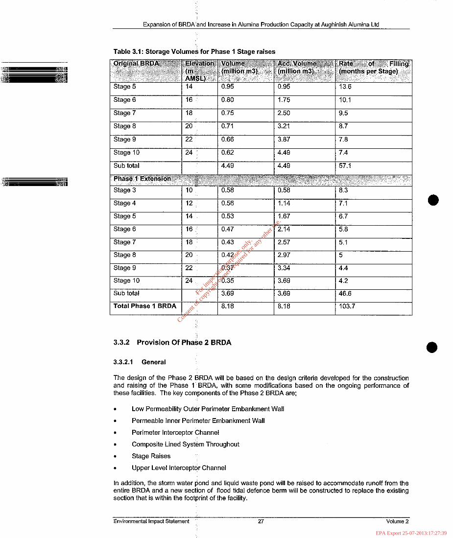
The storage volume for given elevations and rate of filling per stage are summarised in Table 3.1. These storage volumes and expected life of the facility are approximate.
The life of the original BRDA from Stage 5 and the Phase 1 extension from Stage 3 is approximately 5.5 years from the end of 2004. For Stages 3 and 5, the total time for completion is 21.9 months, which results in a rise of approximately 11 OOmm per year. However, the two stages have to be raised together and not Stage 5 followed then by Stage 3. The rate for Stage 3 filled in isolation would then be equivalent to 3000mm per year.
For Stage 7 (original BRDA) and Stage 5 (Phase 1 extension) the combined rate of rise is 1500mm per year. By the later life of Stage 7 and Stage 5, the adjacent Phase 2 BRDA will be operational which would then be used together with Phase 1 as a disposal area to reduce the rate of rising and allow more time for the mud to mature.
For
insp
ectio
n pur
pose
s only
.
Conse
nt of
copy
right
owne
r req
uired
for a
ny ot
her u
se.
EPA Export 25-07-2013:17:27:39
Expansion of BRDA and Increase in Alumina Production Capacity at Aughinish Alumina Ltd
Table 3.1: Storage Volumes for Phase 1 Stage raises
Stage 6 1 16 1 0.80
Stage 7 I I
18 0.75
Stage 8 20 0.71
Stage 9 22 0.66
Stage 10 24 0.62
Sub total 4.49
Stage 4 12 0.56
Stage 5 14 0.53
Stage 6 16 0.47
Stage 7 18 0.43
Stage 8 20 0.42
Stage 9 22 0.37
Stage 10 24 0.35
Sub total 3.69
Total Phase 1 BRDA 8.18
3.3.2 Provision Of PhaSe 2 BRDA
1.75 10.1
2.50 9.5
3.21 8.7
3.87 7.8
4.49 7.4 I
4.49 57.1
1.14 7.1
1.67 6.7
2.14 5.8
2.57 5.1 I
2.97 5
3.34 4.4
3.69 4.2
3.69 46.6
8.18 103.7
3.3.2.1 General
The design of the Phase 2 BRDA will be based on the design criteria developed for the construction and raising of the Phase 1 BRDA, with some modifications based on the ongoing performance of these facilities. The key components of the Phase 2 BRDA are;
. Low Permeability Outer Perimeter Embankment Wall
. Permeable inner Perimeter Embankment Wall
. Perimeter Interceptor Channel
. Composite Lined System Throughout
. Stage Raises
. Upper Level Interceptor Channel
In addition, the storm water pond and liquid waste pond will be raised to accommodate runoff from the entire BRDA and a new section of flood tidal defence berm will be constructed to replace the existing section that is within the footprint of the facility.
Environmental Impact Statement 27 Volume 2
For
insp
ectio
n pur
pose
s only
.
Conse
nt of
copy
right
owne
r req
uired
for a
ny ot
her u
se.
EPA Export 25-07-2013:17:27:39
Expansion of BRDA and Increase in Alumina Production Canacitv at Auahinish Alumina Ltd
The new Phase 2 BRDA will be completely composite lined and surrounded by a perimeter interceptor channel, which is formed by constructing the outer and inner perimeter embankment walls. The channel will connect to the Phase 1 perimeter interceptor channel on the western section. The outline of Phase 2 is presented in Figure 3.6 and combined with Phase 1 ,in Figure 3.7 to show the final contours of the entire BRDA on completed construction and filling.
The ground level within the footprint of the site varies from OmAMSL to 16mAMSL and therefore the perimeter interceptor channel, the inner and out perimeter embankment walls and future raising of the stack,walls will need to accommodate these changes of elevation.
General sections through the proposed Phase 2 BRDA showing the outer ‘and inner perimeter embankment walls with some initial stack raises are presented in Figure 3.8. Details of the Stage raises up to Stage 10 are similar to the Phase 1 BRDA, which are given in Figure 3.2.
3.3.3 Outer Perimeter Embankment Wall
This structure forms the outer wall of the perimeter interceptor channel and acts as the main access road around the facility. The width of the top of the embankment will be 5m. Details of the structures are presented in Figure 3.9.
The upstream and downstream sides slopes vary depending on the foundation materials the structure is placed on. On the weaker foundation materials, in particular where the Phase 2 BRDA encroaches on the mud flats of the Robertstown River, the side slope will be 4H:lV (where H=horizontal and V=vertical). The strength of the foundation materials beneath the embankment wall on the mud flats will be investigated prior to the detailed design. The structure founded on the estuarine soils and glacial tills on dry land will be constructed with upstream and downstream side slopes of 3H:lV. These will be found on the southern and western flanks. In all these cases the crest elevation is at 5mAMSL
Along the central section of the southern flank, the outer perimeter interceptor embankment wall is constructed in cut with a side slope of 3H:lV and a crest elevation of SmAMSL.
On the eastern flank, the ground rises and the foundation material is likely to be placed on bedrock or glacial till. The side slopes of the structure have been steepened to 2H:lV to reflect these stronger foundation materials. The exception is where the embankment wall crosses the backfilled Poulaweala Creek. At this location, the current ground elevation is 2mAMSL. It’may be necessary to remove any unsuitable soft foundation material which formed the base of the creek, reinforce the foundations or reduce the side slopes.
On the eastern flank the crest level of the outer perimeter embankment wall rises from 5mAMSL to 8mAMSL, from 8mAMSL to 1 OmAMSL and from 1 OmAMSL to 16mAMSL. At this elevation it connects to the access road of the Phase 1 extension. At 16mAMSL it also forms the outer wall of the upper interceptor channel (Figure 3.10). The outer perimeter embankment wall cuts across an unsuitable stockpile area, which will have to be removed, prior to connecting with the access road of the Phase 1 extension. The change in elevation of the outer perimeter embankment walls will be accommodated by a series of ramps at maximum side slopes of 6H:lV.
The construction detail of the outer perimeter embankment wall on the eastern flank is similar to the structure proposed on the southern and western sides. Where the crest elevation is at SmAMSL, water contained in the perimeter interceptor channel may be in contact with the inner face. In these cases, the composite lining will consist of a layer of processed glacial till, underlying a HDPE geomembrane (Figure 3.9).
The bulk of the embankment wall will consist of random rockfill. To prevent migration of fine material from the glacial till into the rockfill, a filter consisting of a geosynthetic fabric liner over processed rockfill will be used.
It may be necessary to raise the crest elevation of the outer perimeter wall above the current design level of 5mAMSL, in order, that the structure can act as a flood tidal defence structure. The
Environmental Impact Statement
.
28 Volume 2
For
insp
ectio
n pur
pose
s only
.
Conse
nt of
copy
right
owne
r req
uired
for a
ny ot
her u
se.
EPA Export 25-07-2013:17:27:40
Expansion of BRDA and increase in Alumina Production Capacity at Aughinish Alumina Ltd
downstream slope will also require protection from wave erosion if the existing flood tidal defence berm fails. The erosion protection will comprise interlocking gabion mattresses and the design will be finalised during the detailed design phase.
3.3.4 Inner Perimeter Embankment Wall
This structure forms the inner wall of the perimeter interceptor channel and is designed with a crest width of either 4m or 8m. The wider crest is to support the mud distribution pipe and water supply pipe for the sprinkler system on the eastern and southern sectors. ‘Figure 3.9.
Details of the structure are given in
The upstream and downstream sides slopes vary depending on the foundation materials on which the structure is placed. The structure founded on the estuarine soils and glacial tills on dry land will be constructed with upstream and downstream side slopes of 2H:lV. These structures are located on the southern and western flanks. In these cases, the crest elevation is at 4-5mAMSL.
Along the central section of the southern flank, the inner perimeter interceptor embankment wall is constructed in cut and will be founded on glacial till or bedrock. In this area, the side slopes are constructed at 2H:lV in order to align with the two embankments constructed on the estuarine soils either side of the cut.
On the eastern flank, the ground rises and the foundation material is likely to be weathered bedrock. The side slopes of the structure have been steepened to 3H:2V to reflect the stronger foundation materials.
Where the inner perimeter’ embankment wall runs parallel to the main plant side access road (causeway), the ground elevation drops to about 2mAMSL at the backfilled Poulaweala Creek. Rather than construct the inner perimeter wall on the natural ground, which would mean an 8m high embankment wall, it is proposed to construct it on the red mud once it has reached an elevation of 8mAMSL.
On the eastern flank, the crest level of the inner perimeter embankment wall rises from 4.5mAMSL to 8mAMSL and from 8mAMSL to IOmAMSL. A section will be built to 16mAMSL which will connect to the inner perimeter embankment wall of the Phase 1 extension and form the upper level interceptor channel (Figure 3.10). The change in elevation will be accommodated by a series of ramps.
The inner perimeter embankment walls will be constructed from random rockfill placed on a series of layers which include processed rockfill, geotextile, HDPE geomembrane and a Im thick layer of processed glacial till.
A filtering system will be installed upstream of the rockfill to prevent the migration of particles of red mud due to water erosion. The filter system is required to retain the fine mud particles but have sufficient permeability to allow the passage of water. The filter system will be either constructed from a combination of processed rockfill and sand or processed rockfill and a geotextile.
A similar design will be used for the inner perimeter walls at crest elevations above the 4.5mAMSL. The exception is where it is constructed on red mud and follows the design section for the Stage raise, and where it joins the inner perimeter wall of the Phase 1 extension. At the connector point (Figure 3.10) it will be necessary to cut through the existing perimeter access road of the Phase 1 extension.
3.3.5 Perimeter Interceptor Channel
The perimeter interceptor channel collects all the runoff from the stack walls and seepage from the red mud. It is formed by the construction of the outer and inner perimeter embankment walls.
For much of its length and for all the western and southern flanks, the perimeter interceptor channel has a top width of 25m and a minimum base width of 4m.
Environmental Impact Statement 29 Volume 2
For
insp
ectio
n pur
pose
s only
.
Conse
nt of
copy
right
owne
r req
uired
for a
ny ot
her u
se.
EPA Export 25-07-2013:17:27:40
Expansion of BRDA and Increase in Alumina Production Capacity at Aughinish Alumina Ltd
The base of the interceptor channel is composite lined with a working top surface. The sequence for the construction of the liner is listed below:
. Concrete Working Surface (1 OOmm thick)
. 1 OOOgrms geotextile
. Smooth 2mm HDPE (2mm thick)
. Processed Glacial Till (Minimum IOOOmm thick on the side slopes and 300mm thick at the tiase)
. Geosynthetic Clay Liner (GCL) (IOmm)
The concrete working surface facilitates machine access to the base of the interceptor channel to clean out any accumulated sediment. However, the problems of accumulating red mud sediment in the base of the perimeter interceptor channel observed in Phase 1 will virtually be eliminated by the filter system to be installed on the upstream face of the stack raises.
The Phase 2 perimeter interceptor channel will be connected to the Phase 1 perimeter interceptor channel by culverts and it is proposed to install two HDPE pipes with flap valves to allow the passage of the effluent water. On the eastern flank, the perimeter interceptor channel will collect the runoff and seepage water from the eastern sector of the BDRA. This will be directed to the south via a system of culverts prior to discharging into the perimeter interceptor channel constructed along the southern flank. Along the eastern flank, and parallel to the main plant access road, the perimeter interceptor channel will not be in operation until much later in the operational life of the Phase 2 BRDA when the red mud is built up to an elevation of 8mAMSL.
Where the Phase 2 meets the Phase 1 extension at the north east corner, the perimeter channel formed at a crest elevation of IGmAMSL, takes water from the upper interceptor channel of Phase 2 to the Phase 1 extension.
An emergency spillway will be installed to discharge excess flood water from a storm event exceeding the design 1 in 200 year event. The contaminant water will spill into a holding area between the outer perimeter embankment wall and the flood tidal defence berm. A section of the flood tidal defence berm is to be realigned as ‘outlined in Section 3.3.9. The storage capacity of the holding area is approximately 20,000m3.
3.3.6 Composite Lining
The original Phase 1 BRDA is unlined while a composite system using HDPE geomembrane on top of GCL was used on the Phase 1 extension. The following section outlines the design of the lining to be used in the Phase 2 extension.
The largest area to be composite lined is the basin area of the BRDA. This will cover an area of almost 65ha. The composite lining will comprise a 1.5mm thick HDPE geomembrane over GCL. As there is insufficient glacial till to form a 1 m thick lining underneath the proposed HDPE geomembrane, it is proposed to use the GCL to form the second lining.
A combination of HDPE geomembrane over GCL and 300mm of glacial till will be used to form a composite lining on top of the downstream slope of the Phase 1 and Phase 1 extension embankment walls. The details of this are shown in Figure 3.9.
Approximately a third of the Phase 2 BRDA footprint encroaches on the townland of Glenbane West. Of this area, there is approximately 7ha where any potential seepage could migrate away from the BRDA and further inland on Glenbane West. The majority of seepage from the Phase 2 BRDA located on Glenbane West will migrate towards the Poulaweala Creek underneath the facility and will be buffered by the saline ground water. In this area, a double composite lining may be installed. This is a very conservative approach and during the detailed design phase, additional site work, topographical survey work and detailed contaminant modelling will be undertaken to determine whether the double composite lining system is required and its lateral extent, should it be required. The double composite lining system will consist of two composite linings of HDPE geomembrane underlain by GCL with a
Environmental Impact Statement 30 Volume 2
For
insp
ectio
n pur
pose
s only
.
Conse
nt of
copy
right
owne
r req
uired
for a
ny ot
her u
se.
EPA Export 25-07-2013:17:27:40

Expansion of BRDA and Increase in Alumina Production Capacity at Aughinish Alumina Ltd
drainage blanket in between. Any leakage through the upper collected in the drainage blanket above the lower composite perimeter interceptor channel.
composite lining system would be lining system and pumped to the
3.3.7 Perimeter Raising
The method of raising the Phase 2 facility is by the upstream method. As in Phase 1, an upper level interceptor channel some 20-m wide will be incorporated at Stage 6. The red mud will be strengthened beneath the stack walls by installing a reinforcing geotextile where required. This would allow the facility to be raised to Stage 10 at an elevation of 24mAMSL and a central discharge elevation of 32mAMSL. The performance of the Phase 1 BRDA will be continuously monitored throughout its life and an intrusive investigation will be undertaken after each raise to assess the strength gains in the red mud and compare to previous years and the design criteria. The results from the monitoring of Phase 1 BRDA will be used to form the basis of the design for raising the Phase 2 BRDA.
The perimeter raises will be constructed of random rockfill placed on either a layer of process sand or a geotextile liner fabric. The sand is primarily used in low spots but also, as with the geotextile, prevents the imported rockfill punching through the red mud. The filter system will be either constructed from a combination of processed rockfill and sand or processed rockfill and a geotextile material. (Figure 3.2).
Each stage of the Phase 2 BRDA will be 2m high except for the first stage, which is 1.5m above the inner perimeter embankment wall at an elevation of 6.0m AMSL.
3.3.8 Upper Level Interceptor Channel
The design criteria for the upper level interceptor channel in the Phase 2 BRDA are the same as outlined in Section 3.3.1.2 for the Phase 1 BRDA. When complete, the Phase 2 upper level interceptor channel will connect with the Phase 1 upper level interceptor channel at two locations, by a series of four culvert pipes (Figure 3.11). On the western flank, the transition is relatively straightforward. On the eastern flank (Figure 3.10), the Phase 2 inner wall of the upper level interceptor channel will have to be built to an elevation of 16mAMSL and connect with the inner wall of Phase 1 at Stage 6
The Phase 2 upper level interceptor channel is designed to discharge from various points along its alignment into the perimeter interceptor channel below (Figure 3.11). At three locations, a HDPE decant pipe is to be installed near the base of the upper interceptor channel for Phase 2. At one of the locations of the decant pipe, a small spillway at an elevation of 15SmAMSL will be installed.
3.3.9 Flood Tidal Defence Berm
The Island of Aughinish is protected from flooding from the Shannon River by a flood tidal defence berm (FTDB) approximately 310 m in length. The south west footprint of the Phase 2 BRDA will encroach on the existing FTDB and this will have to be replaced. The section to be replaced is approximately 310 m in length. The design of the flood tidal defence berm (FTDB) will accommodate a 1 in 200 year storm/flood event (UK Environmental Agency Standard). The location of the new section of the FTDB is shown in Figure 3.6.
A section through the flood protection embankment wall is presented in Figure 3.12. The upstream and downstream side slopes are designed with an overall slope of 4H:lV.
The sea ward slope incorporates a stepped gabion mattress to a height of 2mAMSL to prevent erosion by water. The remaining platform base of the embankment wall will be constructed with random rockfill with a central processed glacial till core protected by filters of processed rockfill. This initial platform will be constructed to a height of 2mAMSL and will be used to provide access for the placement of the upstream gabions. A layer of processed rockfill followed by a geotextile liner will be placed prior to placing the glacial till to complete the embankment wall.
Environmental Impact Statement 31 Volume 2
For
insp
ectio
n pur
pose
s only
.
Conse
nt of
copy
right
owne
r req
uired
for a
ny ot
her u
se.
EPA Export 25-07-2013:17:27:40

Expansion of BRDA and Increase in Alumina Production Capacity at Aughinish Alumina Ltd
The existing flood tidal defence berm has a flap valve incorporated into the structure to allow surface runoff water to be discharged into the Robertstown River. Because of the limited catchment area remaining after the Phase 2 BRDA is in operation and the need to have an emergency holding area for potential flood water runoff from the BRDA at this point, no valve will be installed in the FTDB and discharge into the Robertstown River will be prevented.
AAL will be responsible for maintaining the FTDB adjacent to Phase 1 BRDA. AAL will also be responsible for the maintenance of the FTDB adjacent to the Phase 2 BRDA once construction commences. The current condition of the existing FTDB will not meet the design criteria proposed for the new FTDB. Therefore, to protect the outer perimeter wall of the BRDA for both Phases 1 and 2, either the existing FTDB will be strengthened and raised or the outer perimeter embankment wall of the BRDA will be used as a secondary defence and protected by gabion mattresses. The optimum solution is to protect the outer perimeter wall. This will be finalised at the detailed design phase.
3.3.10 Disposal Capacity, Life and Rate of Rise of the Red Mud Phase 2 BRDA. The storage capacity of the Phase 2 BRDA, together with the life and rate of rise are given in Table 3.2 for a red mud disposal volume of 1 ,000,000m3 per annum;
The life of 14.2 years is from the commencement of discharge of red mud into Stage 8 of the Phase 1 BDRA and subject to the performance of the structure during its life.
These values relate to all the red mud being discharged into Phase 2 BRDA. The rate of rising could be reduced if some of the red mud is discharged into the Phase 1 facility.
Table 3.2a: Storage Volumes for Phase 2 Stage raises
Stage 1 6.0 1 65 1 2.74 1 2.7 1 1545 Stage 2 8.0 1 69 14.11 1 4.1 1 1455 !
If the red mud disposal to the Phase 2 BDRA is restricted to 816,000m3 per annum, with the remainder (184,000m3) being discharged to the Phase 1 BDRA from Stage 8 onwards, the rate of rising will decrease. The changes in the rate of rising and life of facility are tabulated below.
Table 3.2b: Storage Volumes for Phase 2 Stage raises
Environmental Impact Statement 32 Volume 2
For
insp
ectio
n pur
pose
s only
.
Conse
nt of
copy
right
owne
r req
uired
for a
ny ot
her u
se.
EPA Export 25-07-2013:17:27:40

Expansion of BRDA And Increase in Alumina Production Capacity at Aughinish Alumina Ltd
The life of 17.4 years is from the commencement of discharge of red mud into Stage 8 of the Phase 1 BDRA and subject to the performance of the structure during its life.
Overall, the life expectancy of the combined Phase 1 and 2 BRDA is approximately 21 years from 2005.
3.4 WATER MANAGEMENT
3.4.1 General
All surface water runoff and leachate from the BRDA will be collected, treated and discharged as outlined in the following sections. Water collected in the Phase 2 perimeter interceptor channel (PIC) will be discharged and pumped to the Phase 1 PIC and from there pumped to the storm water pond (SWP). From the SWP, the water will then be pumped to the south pond before being treated in order to reduce the pH and remove suspended solids. Following treatment the water is pumped to the liquid waste pond (LWP) prior to discharge into the Shannon. Some water is returned to the SWP if the west pond at the plant site is greater than 50% full.
Due to the increase in surface area of the BRDA, there will be an increase in the amount of surface water runoff. In order to prevent run off water from the BRDA facility spilling out from the PIC and SWP, a number of modifications will be made to the BRDA Water Management System. These will include raising and relining the SWP and raising the LWP. A more detailed description of the surface water management system is given Chapter 14 Drainage of this volume of the EIS.
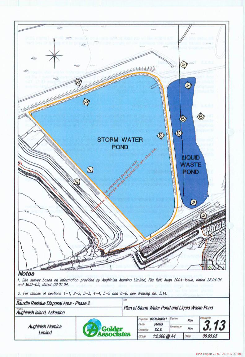
3.4.2 Storm Water Pond Raising
The SWP is to be refurbished by installing a composite lining and increasing the storage capacity by raising the crest height. The current crest height of the SWP is 4.7mAMSL. The internal wall between the SWP and the PIC is at an elevation of 3.85m. The height of the crest will be raised to an elevation of 6.0m AMSL which will be achieved by a combination of making the existing embankment side slopes steeper and installing gabions. Glacial till will be used as fill material for construction. Further details are illustrated in Figures 3.13 and 3.14.
The residual effluent water will be removed from the SWP by pumping and either discharged directly into the plant effluent treatment system or into the completed Phase 2 BRDA. The basin of the SWP will be cleaned of all sediment. The sediment will be placed into geotextile bags to dewater and placed on the BRDA of either Phase 1 or Phase 2. The existing lining system will be removed and disposed of in Phase 1.
During construction, the water level in the PIC and the LWP will be reduced as far as practically possible to reduce any seepage into the excavation of the SWP.
The SWP will be composite lined with combination of GCL and processed glacial till on the side slopes overlain by a HDPE geomembrane liner. If the floor of the basin is dry, GCL could be placed directly on a prepared floor or over a protective geotextile. However, if the basin floor shows any signs of seepage or water it would be preferable to use a 1 m thick layer of processed glacial till.
3.4.3 Liquid Waste Pot-k! Raising
The current crest elevation of the LWP is 4.7mAMSL. A plan of the LWP is presented in Figure 3.14.
The current storage of the LWP will also be increased. The LWP will be raised to a crest elevation of 6.OmAMSL which could be achieved by a combination of steepening the existing embankment side slopes and with gabions. The raising of the LWP will have to be carried out with the facility operating which means that all upstream slopes will be raised by using gabions.
Environmental Impact Statement 33 Volume 2
For
insp
ectio
n pur
pose
s only
.
Conse
nt of
copy
right
owne
r req
uired
for a
ny ot
her u
se.
EPA Export 25-07-2013:17:27:40

Expansion of BRDA and Increase in Alumina Production Capacity at Aughinish Alumina Ltd
The side slopes on the downstream side of the LWP where it adjoins the bird sanctuary will be steepened. The fill used for construction will be glacial till which would need to be keyed into the existing embankment wall.
The existing lining will be extended up the natural slope although a bench will be cut into the natural ground to provide a degree of safety to the lining crew.
The raising of the LWP will ‘be composite lined using a combination of GCL overlain by a HDPE geomembrane for the gabion raise and on the natural ground.
The LWP will be raised before the raising of the SWP. After the completion of the raising of the SWP, the effluent in the LWP will be temporarily stored in the SWP. This will allow inspection and repair of the existing basin lining in the LWP.
3.5 CONSTRUCTION
3.5.1 Outline Construction Plan An outline Construction Plan has been developed as part of the design for the proposed Phase 2 extension. The Plan allows a full construction season, April to September for the construction of the outer perimeter wall and two seasons to place the lining and inner perimeter wall. This is presented as a guide only.
Because of the volume of rockfill required; construction of the inner perimeter embankment wall and hauling from the quarry will be over a period of 56 weeks. It is assumed that hauling from the local quarry will also occur over winter. The number of trips required per day based on a six day week and 20 tonne trucks, is 104 or approximately 10 per hour, with more in the summer and less in the winter.
The Barrigone Quarry operated by Roadstone is located nearby and is a likely source of material. A truck can manage two trips per hour and assuming some downtime six trucks will be required per day.
The construction volumes for the works are relatively small and the expected plant required would be as follows;
.
. 0
.
.
.
.
.
.
.
.
.
.
.
.
Ten 25 tonne dumptrucks,
Three 40 tonne tracked excavators,
One 40 tonne tracked excavator with rock breaker,
One 25/30 tonne wide tracked excavator,
One JCB
Two D6 dozers,
One D4 wide tracked dozer,
One D8/D9 with ripper,
Two vibrating screens,
Two vibrating compactors,
Two Bowsers
One 14G grader,
Two rubber tyre front end loader
One fuel truck
i.. Environmental Impact Statement 34 Volume 2
For
insp
ectio
n pur
pose
s only
.
Conse
nt of
copy
right
owne
r req
uired
for a
ny ot
her u
se.
EPA Export 25-07-2013:17:27:40

Expansion of BRDA and Increase in Alumina Production Capacity at Aughinish Alumina Ltd
The majority of the on-site rock will be obtained by ripping or using a rock breaker mounted on the excavator. A limited amount of rock blasting may be required and this would be sub-contracted to a blasting specialist. No materials will be exported from site. The quantities of materials required for construction are detailed in Chapter 18 Material Assets - Natural and Other Resources
The number of workers required is estimated to be about 40 for the earth moving and 16 for the liner installation. Four further workers would be required if blasting takes place, while the piezometer drilling would require another three workers. Approximately six drivers would be needed for hauling the rockfill.
The civil construction phase of the development is expected to commence in 2007 and be carried out over a 24 month period. Residue tilling operations are proposed to begin in the extension area in approximately late 2009.
3.5.2 Site Preparation
A considerable amount of site preparation will be required prior to the construction of the embankment walls and placement of the composite lining. The key components of the site preparation required prior to construction are:
. Removal of trees
. Removal of hedges and shrubs/vegetation
. Removal of tree stumps
. Removal of organics from the existing surface drainage ditches
* Reshaping and backfilling existing surface drainage ditches
’ . Removal of topsoil
. Removal of existing unsuitable stockpiles beneath the embankment footprint
. Rerouting of 38kV and I OkV power lines
352.1 Removal of Trees, Vegetation and Stumps
Part of the BRDA footprint is covered with plantation trees. The trees are owned by AAL and are deemed by them to have no-economic value. Prior to their removal, the various species of trees will be counted and identified and a’felling licence will be obtained. If possible the trees will be transported to a timber processing facility after felling. Otherwise they will be turned into wood chippings and the branches shredded. These products will be mixed with the topsoil for later use in the restoration of the facility.
The chippings and shreddings generated will be transported to the proposed topsoil stockpile area periodically during the operation.
As the trees are being felled,’ the roots and stumps will need to be removed and where appropriate will be shredded and mixed with topsoil. Stumps and roots which would be difficult to shred will be placed in the unsuitable stockpile for later restoration use.
3.5.2.2 Backfilling Existing Drains
There is some 3000m of existing drainage ditches that need to be backfilled prior to the placement of the composite lining. The drainage ditches will be cleaned of all vegetation and organic debris from
Environmental Impact Statement 35 Volume 2
For
insp
ectio
n pur
pose
s only
.
Conse
nt of
copy
right
owne
r req
uired
for a
ny ot
her u
se.
EPA Export 25-07-2013:17:27:40
Expansion of BRDA and Increase in Alumina Production Capacity at Aughinish Alumina Ltd
the sides and base. The drains will be cut back to side slopes no steeper than 3H:2V, Terram 2000 will be placed and cobbles and boulders will be placed from the processing of the glacial till and from the unsuitable stockpile.
. 3.5.2.3 Removal of Topsoil
The topsoil will be stripped and temporarily stockpiled for use in the restoration of the side slopes of both Phases I and 2. Topsoil designated for the rehabilitation of the lower slopes in Phase 1 will be placed immediately. The remaining topsoil will be stockpiled in a designated area (Figure 18.1). The stockpiles shall not exceed a height of 5m and side slopes shall not exceed 2H:lV. The total volume of topsoil to be removed is approximately 200,000m3.
3.5.2.4 Removal of Unsuitable Stockpile
The existing unsuitable stockpile located in the northeast sector of the Phase 2 BRDA at the location where it connects to the Phase 1 BRDA will be removed. A series of pits will be excavated through the stockpile to determine the condition of the foundation materials, which is expected to be bedrock limestone with possibly a thin layer of glacial till.
The volume of material that may require to be removed is expected to be of the order of 50,000m3. The organic and soft estuarine material will be mixed in with the topsoil stockpile whilst the cobbles and boulders from the processing of the glacial till will be used for backfilling the existing drainage ditches in the proposed Phase 2 BRDA construction area.
3.6 QUALITY ASSURANCE The BRDA will be constructed in accordance with the technical specification and construction drawings as shown in this EIS and developed during the detailed design phase.
3.6.1 Quality Control And Assurance Programme A comprehensive quality control and assurance programme will be carried out during the construction of the facility. The following aspects will be carefully monitored during the construction phase by suitably qualified personnel:
. Embankment footprint foundation preparation;
. Selection of suitable materials for embankment wall;
. Moisture conditioning and com,paction of embankment wall fill materials;
. Alignment and level of any pipework;
l Selection and installation of pipes, bedding and drainage material;
. Pore pressure monitoring in the estuarine and glacial foundation materials.
Quality control tasks including classification tests, gradations, moisture content, permeability and density tests will be carried out throughout the construction phase to ensure compliance with the technical specifications and construction drawings.
Environmental Impact Statement 36 Volume 2
For
insp
ectio
n pur
pose
s only
.
Conse
nt of
copy
right
owne
r req
uired
for a
ny ot
her u
se.
EPA Export 25-07-2013:17:27:40
For
insp
ectio
n pur
pose
s only
.
Conse
nt of
copy
right
owne
r req
uired
for a
ny ot
her u
se.
EPA Export 25-07-2013:17:27:40
For
insp
ectio
n pur
pose
s only
.
Conse
nt of
copy
right
owne
r req
uired
for a
ny ot
her u
se.
EPA Export 25-07-2013:17:27:40

For
insp
ectio
n pur
pose
s only
.
Conse
nt of
copy
right
owne
r req
uired
for a
ny ot
her u
se.
EPA Export 25-07-2013:17:27:40
For
insp
ectio
n pur
pose
s only
.
Conse
nt of
copy
right
owne
r req
uired
for a
ny ot
her u
se.
EPA Export 25-07-2013:17:27:41
For
insp
ectio
n pur
pose
s only
.
Conse
nt of
copy
right
owne
r req
uired
for a
ny ot
her u
se.
EPA Export 25-07-2013:17:27:41
For
insp
ectio
n pur
pose
s only
.
Conse
nt of
copy
right
owne
r req
uired
for a
ny ot
her u
se.
EPA Export 25-07-2013:17:27:41