3-d shape measurement of pipe by range finder …yamashita/paper/b/b061final.pdf · inspection...
TRANSCRIPT

0
Abstract— A lot of plumbings such as gas pipes and water
pipes exist in public utilities, factories, power plants and so on. It
is difficult for humans to inspect them directly because they are
long and narrow. Therefore, automated inspection by robots
equipped with camera is desirable, and great efforts have been
done to solve this problem. However, many of existing inspection
robots have to rotate the camera to record images in piping
because a conventional camera with a narrow view can see only
one direction while piping has a cylindrical geometry. The use of
an omni-directional camera that can take images of 360° in
surroundings at a time is effective for the solution of the problem.
However, the shape measurement is difficult only with the
omni-directional camera. Then, in this paper, we propose a
reconstruction method of piping shape by using an
omni-directional camera and an omni-directional laser with a
light section method and a structure from motion analysis. The
validity of the proposed method is shown through experiments.
I. INTRODUCTION
A lot of plumbings such as gas pipes and water pipes exist
in public utilities, factories, power plants and so on. These
facilities are important and indispensable for our lives.
However, these pipes become deteriorated by aging and
internal damage comes to existence. If the damage grows large,
a serious accident may happen.
To find such damage at the early stage, and to take
precautions against possible accidents, it is important to
recognize the pipe state. However it is difficult for humans to
inspect the pipe state directly because they are long and
narrow and often laid underground. Therefore, automated
inspection by robots equipped with camera is desirable and
many efforts have been done to solve the problem
[1][2][3][4][5][6].
However, many of existing inspection robots have to rotate
the camera to record images in piping because a conventional
camera with a narrow view can see only one direction while
piping has a cylindrical geometry. There is a problem that
inspection robot have to stop every time at the point where the
robot records the image. Therefore, it takes long time to
measure pipe shape.
On the other hand, vision sensors with a wide field of view
have been invented; e.g. a fisheye camera and an
omni-directional camera. They have a variety of potential
applications, such as mobile robot navigation [7], and
K. Matsui, A. Yamashita and T. Kaneko are with Department of
Mechanical Engineering, Shizuoka University, 3–5–1 Johoku, Naka-ku,
Hamamatsu-shi, Shizuoka 432–8561, Japan (phone: 053-478-1604; fax:
053-478-1604; e-mail: {f0930058, tayamas, tmtkane}@ipc.shizuoka.ac.jp)
telepresense technology [8]. Particularly, previous studies
showed that an omni-directional camera is effective in
measurement and recognition of environment [9].
Kannala et al. proposed a pipe inspection method using
omni-directional vision sensor for robot vision [10]. The use
of the omni-directional vision sensor that can take images of
360°in surrounding at a time is effective for pipe inspection.
They use the structure from motion analysis which is a kind of
passive measurement. However, the method has to extract and
track feature points to get corresponding points between
images. If corresponding point detection fails, the
measurement accuracy decreases.
To solve this problem, a light section method which is a
kind of active measurement is proposed instead of passive
measurement like the structure from motion. The light section
method has an advantage that the method usually has no
difficulty in finding corresponding points. Therefore,
measurement is more reliable than structure from motion
analysis and the method is used in various fields [11][12].
However, in general, the light section method requires that
the position and the orientation of the camera be constant
while measurement. If the camera moves, it is difficult to
integrate of the measurement results. Therefore, the camera
motion estimation (the relative relations of camera positions
and orientations) is important for the measurement. The idea of light section method with omni-directional camera can be
found in works such as papers [13][14].
Yi et al. do not describe camera motion estimation.
Orghidan et al. proposed a camera motion estimation method
based on ICP algorithm. However, the method is difficult for
estimation of six degrees of freedom. On the other hand, the structure from motion analysis has the advantage that it can
estimate the camera motion with 3-D measurement. Thus, the
method is used not only for pipe inspection but also for
construction of an environment map [15][16].
We have already proposed a reconstruction method of pipe
shape with a light section method and a structure from motion
analysis [17]. There is a problem that the texture information
was not considered. The texture information is important for
pipe inspection. Therefore, a 3-D pipe model which has shape
information and texture information is effective for
recognition of pipe state.
In this paper, we propose a 3-D measurement method using
an omni-directional camera and an omni-directional laser with
a light section method and a structure from motion analysis.
Our method calculates 3-D coordinates by the light section
method. The individual measurement data is integrated with
3-D Shape Measurement of Pipe by Range Finder Constructed with
Omni-Directional Laser and Omni-Directional Camera
Kenki Matsui, Atsushi Yamashita and Toru Kaneko
Laser Light
r
f(r) f(i)
f(i-1) f(i+1)
d
ii+d r
f(r) f(i)
f(i-1) f(i+1)
f(i)
f(i-1) f(i+1)
f(i)
f(i-1) f(i+1)
dd
ii+di+d
the information of camera motion estimated by the structure
from motion analysis. By pasting textures on the measurement
data, a 3D Pipe model is generated.
II. OUTLINE
An inspection robot executes 3-D measurement by using a
rangefinder constructed with a omni-directional camera
(Fig.1) and a laser source that can emit laser light in all
direction orthogonal to the head (Fig.2).
The process of our method is shown in Fig.3. As the first
step, the inspection robot acquires an omni-directional image
sequence during its locomotion while emitting laser light.
The second step calculates 3-D coordinates of measurement
points by the light section method.
The third step estimates a camera motion by the structure
from motion method and integrates measurement results.
Finally, a triangular mesh is generated from the
measurement results. By texture mapping to the triangular
mesh, the 3-D model of pipe is reconstructed.
Fig.1 Omni-directional camera Fig.2 Omni-directional laser
III. 3-D MEASUREMNT
We use the light section method for 3-D measurement.
First, we extract image coordinates of laser light from an
omni-directional image sequence.
Then, the 3-D coordinates of measurement point are given
as the cross-point of a ray vector and the laser light.
A. Laser Light Extraction
The laser light reflected by the measurement object is
captured by the omni-directional camera as a circular area
with some width. Therefore, we have to extract the peak (the
pixel that has the highest intensity) from the area that can be
considered as the laser light on image. We use the Gaussian
approximation method [18] to extract the peak.
In order to detect the laser light, we scan radially around the
center of the omni-directional image (Fig.4). We approximate
the changing of intensity value in the radial direction to the
Gaussian distribution (Fig.5).
Then, we select the three highest intensity values from the
laser light. The subpixel offset d is calculated from these
values by Eq.(1).
Fig.4 Radial scanning Fig.5 Gaussian distribution
))1(ln())(ln(2))1(ln(
))1(ln())1(ln(
2
1
++−−
+−−=
ififif
ififd (1)
where f(i) denotes the intensity at i which is an image
coordinate of the observed peak.As a result, (i + d) is obtained
as the image coordinate of the laser light.
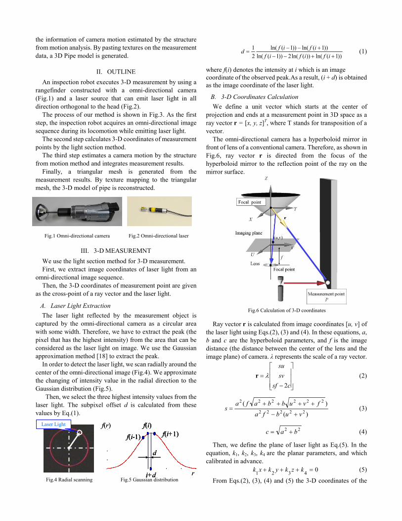
B. 3-D Coordinates Calculation
We define a unit vector which starts at the center of
projection and ends at a measurement point in 3D space as a
ray vector r = [x, y, z]T, where T stands for transposition of a
vector.
The omni-directional camera has a hyperboloid mirror in
front of lens of a conventional camera. Therefore, as shown in
Fig.6, ray vector r is directed from the focus of the
hyperboloid mirror to the reflection point of the ray on the
mirror surface.
Fig.6 Calculation of 3-D coordinates
Ray vector r is calculated from image coordinates [u, v] of
the laser light using Eqs.(2), (3) and (4). In these equations, a,
b and c are the hyperboloid parameters, and f is the image
distance (the distance between the center of the lens and the
image plane) of camera. λ represents the scale of a ray vector.
−
=
csf
sv
su
2
λr (2)
)(
)(
22222
222222
vubfa
fvubbafas
+−
++++= (3)
22bac += (4)
Then, we define the plane of laser light as Eq.(5). In the
equation, k1, k2, k3, k4 are the planar parameters, and which
calibrated in advance.
04321
=+++ kzkykxk (5)
From Eqs.(2), (3), (4) and (5) the 3-D coordinates of the

measurement point is calculated by Eq.(6).
−−++
−=
csf
sv
su
csfksvksuk
k
z
y
x
p
p
p
2)2(321
4 (6)
IV. CAMERA MOTION ESTIMATION
We use a structure from motion analysis for camera motion
estimation [19].
First, the robot acquires an omni-directional image
sequence during its locomotion. Second, the method extracts and tracks feature points to get
corresponding points in the omni-directional image sequence.
The camera motion is estimated by the linear estimation,
which uses the positions of corresponding points in two
images taken at each observation point.
In order to estimate the camera motion more precisely,
re-estimation of camera motion is performed with nonlinear
estimation.
A. Corresponding Point Acquisition
For getting corresponding points between images in the
omni-directional image sequence, the method extracts feature
points in the first image and then tracks them along the
sequence. In our method, we use SIFT (Scale Invariant
Feature Transform) algorithm [20].
First, we extract feature points. By comparing these points
between two images taken before and after the robot
movement, we get corresponding points which are regarded as
the same point in 3-D space (Fig.7).
B. Estimation of Camera Motion
In order to estimate camera motion, we calculate the
essential matrix which contains information about relative
position and orientation differences between two observation
points.
Essential Matrix E satisfies Eq.(7).
0=′ iT
i Err (7)
(a) Image acquired before (b) Image acquired after
robot movement robot movement
Fig.7 Corresponding point acquisition
where ri = [xi, yi, zi] T , ri’ = [x’i, y’i, z’i]
T are the ray vectors of
the corresponding point in two images, respectively. Equation
(7) is transformed into Eq.(8).
0=euTi (8)
where
ui=[xix’i, yix’i, zix’i, xiy’i, yiy’i, ziy’i, xiz’i, yiz’i, ziz’i]T
e=[e11, e12, e13, e21, e22, e23, e31, e32, e33]T
Essential matrix E is obtained by solving simultaneous
equations for more than eight pairs of corresponding ray
vectors. This means that we solve Eq.(9).
2
min Uee
(9)
where U = [u1, u2, ・・・,un]T. Essential matrix E is obtained
from e which is given as the eigenvector of the smallest
eigenvalue of U TU .
From essential matrix E, we calculate rotation matrix R and
translation vector t.
Essential matrix E is represented by rotation matrix R and
translation vector t = [tx, ty, tz] T.
RTE = (10)
Here, T is a matrix given as follows.
−
−
−
=
0
0
0
xy
xz
yz
tt
tt
tt
T (11)
However, all feature points tracked along the image
sequence do not behave as corresponding points because of
image noise. Mistracked Feature points should be rejected as
outliers. To solve this problem, we employ a method of
RANSAC (RANdom SAmple Consensus) [21].
In the procedure, we select randomly eight feature points,
which are the minimum number of points for determining
essential matrix E. Let Erand be the essential matrix determined
by using these feature points, and k be the number of feature
points satisfying Eq.(12), where q is a given threshold.
qi
T
i <′ rEr rand (12)
We repeat this process of determining essential matrix Erand
and number k for predetermined times. Then we choose the
case with the maximum number of k, and remove feature
points that do not satisfy Eq.(12) as outliers.
Finally, we calculate essential matrix E by Eq.(9) using the
remaining feature points.
C. Re-Estimation of Camera Motion
The Rotation matrix and the translation vector estimated in
Section 4.3 may not be always good results because of various
errors in images. Then, we re-estimate the camera motion in
consideration of the measurement errors in each feature point.
We use bundle adjustment [22] for re-estimation of the
camera motion. The method minimizes the sum of feature
reprojection errors which means difference between the image
coordinates of the original feature point and the reprojected
point.
D. Scale Match Method
The structure from motion analysis cannot determine the
distance |t| between two observation points because the
measurement only uses images for input and does not get any
scale information.

However, the 3-D coordinates of point measured by the
light section method includes scale information. Therefore,
we use the measurement result by the light section method for
scale matching.
First, we measure the 3-D coordinates of a point by the light
section method. The 3-D coordinates of the same point are
measured by the structure from motion analysis (the green
circle in Fig.8). The ray vector is calculated from
corresponding points. Template matching based on
normalized cross-correlation is used for getting corresponding
points. Then, the 3-D coordinates of the point are given as
those of the cross-point of two ray vectors.
(a) Measurement (b) Measurement
by light section method by structure from motion
Fig.8 Scale matching
Scale matching is realized by making the 3-D coordinates
of the same point as close as possible. Minimization of
deviation of the two resultant coordinates of the same point is
more sensitive when the point lies farther from the observation
point. Therefore it is appropriate to minimize the distances of
coordinates. Scale 's is calculated by Eq.(13).
∑=
′−m
kkk s
1
2)log()log(min pp (13)
where pk = [xk, yk, zk] T represents the measurement result by
the light section method, and pk’ = [xk’, yk’, zk’]
T represents the
measurement result by the structure from motion analysis. By
the procedure, we can integrate the individual measurement
data with matched scale.
V. TEXTURE MAPPING
A triangular mesh is generated from integrated
measurement data by using the 3-D Delaunay triangulation.
But, the Delaunay triangulation generates a triangular mesh
which contradicts a physical shape because the triangular
mesh does not consider the shape of the measurement object.
Therefore, we apply the triangular optimization method [23]
to the triangular mesh. The method adapts the triangular mesh
to the physical shape by detecting a texture distortion. By
texture mapping to the triangular mesh, a 3-D environment
model is constructed.
VI. EXPERIMENTS
In the experiment we measured two objects. One is a
rectangular container and the other is a pipe. The size of input
image is 1920x1080 pixels.
In 3-D measurement, we used images without ambient
illumination. Also, in camera motion estimation, we used
images with ambient illumination.
A. Accuracy Evaluation Experiment
The experimental environment is shown in Fig.9.
We fixed an omni-directional camera and an
omni-directional laser to a jig (Fig.10). The laser light was
emitting while lifting the jig in container. Then, we acquired
an image sequence by using the omni-directional camera.
Figures 11 and 12 show acquired images with ambient
illumination and without ambient illumination. Figure 13
shows the result of measurement. The result shows our
proposed method can reconstruct the 3-D shape of the
container.
Table 1 shows the standard deviations from the least square
planes. Table 2 shows angles between two planes calculated
by a least square method and Table 3 shows the distances
between corner points.
The errors of distances between corner points are within the
theoretical value of our proposed method.
Fig.9 Experimental environment 1 Fig.10 Measurement device 1
Fig.11 Image with ambient Fig.12 Image without ambient
illumination 1 illumination 1
Fig.13 Reconstruct of container
Table 1 Standard deviations from the least square error plane
Standard deviation
Front Surface 1.08mm
Rear Surface 0.88mm
Left Surface 0.85mm
Right Surface 0.69mm

A
B
C
100mm
100mm
A
B
C
100mm
100mm
Table 2 Angles between two least square error planes
Measurement
value
Ground
truth
Front and Left Surfaces 90.4deg 90.0deg
Rear Surface and Left Surface 89.6deg 90.0deg
Front Surface and Right Surface 90.6deg 90.0deg
Rear Surface and Right Surface 89.4deg 90.0deg
Table 3 Distances between corner points
Measurement value Ground truth
Front Surface 282mm 285mm
Rear Surface 283mm 285mm
Left Surface 567mm 570mm
Right Surface 568mm 570mm
B. Measurement Experiment
We prepare a pipe as a measurement object and performed
an accuracy evaluation of shape reconstruction. Also we
prepare a manipulator and installed an omni-directional
camera and an omni-directional laser. The accuracy
evaluation of camera motion estimation is performed by using
the trajectory information of manipulator
The experimental environment is shown in Fig.14. Figure
15 shows the actual image of the pipe. Assuming the case
where the imperfection exists in the pipe, we added a
projection to the pipe as shown in Fig. 16. The camera moved
with the manipulator as shown in Fig. 17.The laser light was
emitting while the manipulator moved in the pipe. Then, we
acquired an image sequence by using the omni-directional
camera.
Figures 18 and 19 show acquired images with ambient
illumination and without ambient illumination, respectively.
Figure 20 shows the estimated camera motion. Color points
represent the measurement results. Black points represent the
ground truth. Table 4 shows the accuracy evaluations of
estimated camera motion. Our proposed method can estimate
the camera motion within a 3mm error margin.
These results show our proposed method can estimate
camera motion while the camera moves arbitrarily.
Figures 21 and 22 show the result with our proposed method
and the result using movement information of the manipulator.
(a) is the bird’s eye view of the experimental result. (b) is the
top view of the experimental result.
By comparing Figs.21 to 22, we can say our proposed
method can reconstruct the pipe shape with high precision.
Table 5 shows comparison of the ground truth values and
the measurement data. In Table 5, the measurement value of
the inside diameter is calculated by cylinder fitting. The result shows our proposed method can measure the pipe with high
precision.
Figures 23 and 24 shows the experimental result of texture
mapping. (a) is the front view. (b) is the internal view. The
result shows our proposed method can measure the pipe in
detail. By using texture information, recognition of the convex
part becomes easy.
Fig.14 Experimental environment 2 Fig.15 Actual image
Fig. 16 Projection Fig.17 Experimental trajectory of the
manipulator
Fig.18 Image with ambient Fig.19 Image without ambient
illumination 2 illumination 2
Fig.20 Estimated camera motion
Table 4 Accuracy evaluations of estimated camera motion
VII. CONCLUSIONS
In this paper, we propose a reconstruction method of pipe
shape by using an omni-directional laser and an
omni-directional camera with a light section method and a
structure from motion analysis. Experimental results showed
the effectiveness of the proposed method.
As future works, we should improve the proposed
rangefinder to emit an illumination light. Also we should
install the proposed rangefinder to inspection robot.
Measurement
value
Ground
truth
Between A and B 102mm 100mm
Between B and C 103mm 100mm

Projection
Projection
(a) Bird’s-eye view (b) top view
Fig.21 Reconstruction of pipe shape with the proposed method
(a) Bird’s-eye view (b) top view
Fig.22 Reconstruction of pipe shape with movement information
of manipulator
Table 5 Accuracy evaluation
Measurement
value Ground truth
Inside diameter 394.8mm 396.4mm
Height 8mm 5mm
Width 7mm 5mm
Depth 103mm 100mm
(a) Front view (b) Internal view Fig.23 Result of texture mapping with our proposed method
(a) Front view (b) Internal view Fig.24 Result of texture mapping with movement information
of manipulator
References [1] A. Ahrary, A..A.F Nassiraei and M. Ishikawa, “A Study of An
autonomous Mobile Robot for a Sewer Inspection System,” Journal of
Artificial Life and Robotics, Vol.11, No.1, pp.23-27, 2007.
[2] K.U. Scholl, V. Kepplin, K. Berns, and R. Dillmann, “Controlling a
Multijoint Robot for Autonomous Sewer Inspection," Proceedings of
the 2000 IEEE International Conference on Robotics and Automation
(ICRA 2000), pp.1701-1706, 2000.
[3] H.B. Kuntze and H. Haffner, “Experiences with the Development of a
Robot for Smart Multisensoric Pipe Inspection,” Proceedings of the
1998 IEEE International Conference on Robotics and Automation
(ICRA 1998), pp.1773-1778, 1998.
[4] A. Zagler, and F. Pfeiffer, “MORITZ a Pipe Crawler for Tube
Junctions,” Proceedings of the 2003 IEEE International Conference on
Robotics and Automation (ICRA 2003), pp.2954-2959, 2003.
[5] M.Horodinca, I.Doroftei and E.Mignon, “A Simple Architecture for
In-Pipe Inspection Robots,” Proceedings of the 2002 International
Colloquium on Mobile and Autonomous Systems, (ICMAS 2002),
pp.1-4, 2002.
[6] K. Suzumori, S. Wakimoto and M. Tanaka, “A Miniature Inspection
Robot Negotiating Pipes of Widely Varying Diameter,” Proceedings
of the 2003 IEEE International Conference on Robotics and
Automation (ICRA 2003), pp.2735-2740, 2003.
[7] J. Gaspar, N. Winters and J. S. Victor, “Vision-Based Navigation and
Environmental Representations with an Omnidirectional Camera,”
IEEE Transactions on Robotics and Automation, Vol.16, No.6,
pp.890-898, 2000.
[8] Y. Yagi, “Omnidirectional Sensing and Its Applications,” IEICE
Transactions on Information and Systems, Vol.E82-D, No.3,
pp.568-579, 1999.
[9] J. Gluckman, and S. K. Nayar, “Ego-motion and Omnidirectional
Cameras,” Proceedings of the 6th International Conference on
Computer Vision, pp.999-1005, 1998.
[10] J. Kannala, S. S. Brandt, and J. Heikkilä, “Measuring and Modelling
Sewer Pipes from Video,” Machine Vision and Applications, Vol.19,
No.2, pp.73-83, 2008.
[11] A. Yamashita, H. Higuchi and T. Kaneko, “Three Dimensional
Measurement of Object's Surface in Water Using the Light Stripe
Projection Method,” Proceedings of the 2004 IEEE International
Conference on Robotics and Automation (ICRA2004), pp.2736-2741,
2004.
[12] Y. Yachide, Y. Oike, M. Ikeda. and K. Asada, “Real-time 3-D
Measurement System Based on Lght-Section Method Using Smart
Image Sensor,” Proceedings of the 2005 IEEE International Conference
on Image Processing (ICIP 2005), pp.III-1008-1011, 2005.
[13] S. Yi, B. Choi, and N. Ahuja: “Real-time Omni-directional Distance
Measurement with Active Panoramic Vision”, International Journal of
Control, Automation, and Systems, Vol.5, No.2, pp.184–191, 2007.
[14] R. Orghidan, E. Mouaddib, J. Salvi: “Omni-directional Depth
Computation from a Single Image”, Proceedings of the 2005 IEEE
International Conference on Robotics and Automation, pp.1234–1239,
2005.
[15] B. Micusik and T. Pajdla: “Structure from Motion with Wide Circular
Field of View Cameras”, IEEE Transactions on Pattern Analysis and
Machine Intelligence, Vol.28, No.7, pp.1135–1149, 2006.
[16] M. Lhuillier: “Automatic Scene Structure and Camera Motion using a
Catadioptric System”, Computer Vision and Image Understanding,
Vol.109, No.2, pp.186–203, 2008.
[17] K. Matsui, A. Yamashita and T. Kaneko, “3-D Shape Reconstruction of
Pipe with Omni-Directional Laser and Omni-Directional Camera,”
Proceedings of the 3rd International Conference of Asian Society for
Precision Engineering and Nanotechnology (ASPEN2009), 1A2-15,
pp.1-5, 2009.
[18] R.B.Fisher and D.K.Naidu, “A Comparison of Algorithms for Subpixel
Peak Detection,” Proceedings of the 1991 British Machine Vision
Association Conference (BMVAC 1991), pp.217-225, 1991.
[19] R. Kawanishi, A. Yamashita and T. Kaneko, “Estimation of Camera
Motion with Feature Flow Model for 3D Environment Modeling by
Using Omni-Directional Camera,” Proceedings of the 2009 IEEE/RSJ
International Conference on Intelligent Robots and Systems
(IROS2009), 2009.
[20] D. G. Lowe, “Distinctive Image Features from Scale-Invariant
Keypoints,” International Journal of Computer Vision, Vol.60, No.2,
pp.91-110, 2004.
[21] M. A. Fischler and R. C. Bolles, “Random Sample Consensus: A
Paradigm for Model Fitting with Applications to Image Analysis and
Automated Cartography,” Communications of the ACM, Vol.24, No.6,
pp.381-395, 1981.
[22] B. Triggs, P. McLauchlan, R. Hartley and A. Fitzgibbon, “Bundle
Adjustment -A Modern Synthesis,” Vision Algorithms: Theory &
Practice, Springer-Verlag LNCS 1883, 2000.
[23] A. Nakatsuji, Y. Sugaya, and K. Kanatani, “Optimizing a Triangular
Mesh for Shape Reconstruction from Images,” IEICE Transactions on
Information and Systems, Vol. E88-D, No. 10, pp. 2269-2276, 2005.