3-d exergy-based methods for improving energy-conversion
TRANSCRIPT

*Corresponding Author Vol. 15 (No. 4) / 201
International Journal of Thermodynamics (IJoT) Vol. 15 (No. 4), pp. 201-213, 2012 ISSN 1301-9724 / e-ISSN 2146-1511 doi: 10.5541/ijot.417 www.ijoticat.com Published online: Oct. 19, 2012
3-D Exergy-Based Methods for Improving Energy-Conversion Systems
Tatiana Morosuk*, George Tsatsaronis
Institute for Energy Engineering, Technische Universität Berlin, Germany
E-mails: [email protected], [email protected]
Abstract
Exergy-based methods (exergetic, exergoeconomic and exergoenvironmental analyses) are powerful tools for
developing, evaluating and improving an energy conversion system. Until now, the exergoeconomic and the
exergoenvironmental analysis have been conducted independently of each other. This paper presents a way for
combining these analyses and for formulating common conclusions for further improvement of an energy
conversion system by taking into account simultaneously the minimization of cost and of environmental impact. An
academic example consisting of a simple air refrigeration machine, serves as an example for demonstrating the
approach.
Keywords: Exergetic analysis; exergoeconomic analysis; exergoenvironmental analysis.
1. Introduction
Thermodynamic, economic, and environmental-impact
analyses are three useful tools used for the evaluation and
improvement (optimization) of an energy conversion
system. These analyses reveal
(a) the real thermodynamic inefficiencies and the
processes that cause them,
(b) the costs associated with equipment and
thermodynamic inefficiencies as well as the
connection between these two important factors,
(c) the environmental impact associated with equipment
and thermodynamic inefficiencies as well as the
connection between these two sources of
environmental impact, and
(d) possible measures that would improve the efficiency
and the cost effectiveness and would reduce the
environmental impact of the system being studied.
An exergoeconomic analysis (Bejan et al, 1996;
Lazzaretto and Tsatsaronis, 2006; Tsatsaronis, 2008)
consists of an exergetic analysis, an economic analysis, and
an exergoeconomic evaluation. An exergoenvironmental
analysis (Tsatsaronis, 2008; Meyer et al., 2009) consists of
an exergetic analysis, a life cycle assessment (LCA) of the
environmental impact and an exergoenvironmental
evaluation conducted in analogy with the exergoeconomic
one.
In the exergoeconomic and exergoenvironmental
analyses (which are already known as powerful tools for
analyzing, evaluating and improving energy-conversion
systems) the economic analysis and the LCA (therefore the
exergoeconomic and the exergoenvironmental analysis) are
conducted independently of each other. Obviously then the
conclusions from these analyses are also obtained
independently.
In this paper we try to obtain consistent conclusions on
how to improve an energy-conversion system by reducing
cost and environmental impact. Note that we do not want to
assign cost values to environmental impacts (or vice versa)
because of the arbitrariness and uncertainty associated with
such procedures. As before, the main assumption is that
data obtained from an LCA and from a cost analysis are
independent from each other.
2. Exergy-Based Analyses
2.1. Exergetic Analysis
Using the exergy rates associated with fuel and product
(Tsatsaronis, 1984; Bejan et al., 1996; Lazzaretto and
Tsatsaronis, 2006), k,FE and k,PE , respectively, the
exergetic balance for the k-th component is
k,Dk,Pk,F EEE (1)
The total exergy destruction within the k-th component (
k,DE ) can be determined through this balance.
The exergetic efficiency for the k-th component is
k,F
k,D
k,F
k,Pk
E
E
E
E
1 (2)
Additional variables used in the exergetic analysis can
be found in many publications, for example, Bejan et al.,
1996; and Lazzaretto and Tsatsaronis, 2006.
2.2. Exergoeconomic Analysis
The exergoeconomic analysis is an exergy-based
method that identifies and calculates the location,
magnitude, causes and costs of thermodynamic
inefficiencies in an energy-conversion system. An
exergoeconomic analysis is conducted at the component
level of a system and reveals (a) the relative cost
importance of each component, and (b) options for
improving the overall cost effectiveness.
The exergoeconomic model of an energy conversion
system (Bejan et al., 1996; Lazzaretto and Tsatsaronis,
2006) consists of cost balances and auxiliary costing
equations.
The cost balances are formulated for each system
component:
202 / Vol. 15 (No. 4) Int. Centre for Applied Thermodynamics
kk,Fk,P ZCC , (3a)
or
kk,Fk,Fk,Pk,P ZEcEc (3b)
Here k,PC and k,FC are the cost rates associated with fuel
and product, whereas cP,k and cF,k are the corresponding
costs per unit of exergy. Finally kZ is the sum of cost rates
associated with capital investment (CI) as well as operating
& maintenance (O&M) expenditures for the k-th component
OMk
CIkk ZZZ (4)
To simplify the discussion, we assumed in the present
paper, that the contribution of OMkZ remains constant when
design changes are made, and, therefore, the changes in the
value of kZ are associated only with changes in the capital
investment cost CIkZ .
The auxiliary costing equations are based on the P and
F rules, as they have been finalized by Lazzaretto and
Tsatsaronis, 2006.
The following exergoeconomic variables may be used
for improving the cost effectiveness of the overall system in
an iterative optimization:
Cost rate associated with the exergy destruction within
the k-th component
k,Dk,Fk,D EcC (5)
Total expenses associated with the component, which
are the sum ( k,DCIk CZ )
Relative cost difference
k,Pk,F
k
k
k
k,F
k,Fk,Pk
Ec
Z
c
ccr
1 (6)
Exergoeconomic factor
k,Dk,FCIk
CIk
k,DCIk
CIk
kEcZ
Z
CZ
Zf
(7)
2.3 Exergoenvironmental Analysis
An exergoenvironmental analysis is an exergy-based
method that identifies and calculates the location,
magnitude, causes and environmental impact of
thermodynamic inefficiencies in an energy conversion
system (Tsatsaronis, 2008; Meyer et al., 2009). An
exergoenvironmental analysis is also conducted at the
component level of a system and identifies (a) the relative
importance of each component with respect to
environmental impact, and (b) options for reducing the
environmental impact associated with the overall system. In
an exergoenvironmental analysis, a one-dimensional
characterization indicator is obtained using a Life Cycle
Assessment (LCA). This indicator is used in a similar way
as the cost is used in exergoeconomics. An index (a single
number) describes the overall environmental impact
associated with system components and exergy carriers.
The Eco-indicator 99 (Goedkoop and Spriensma, 2000) is
an example of such an index and is used here. It should be
emphasized that the evaluation of environmental impacts
will always be subjective and associated with uncertainties.
However, the information extracted from the
exergoenvironmental analysis is very useful, and future
work should also focus on reducing the arbitrariness
associated with the LCA and the index used in the analysis.
The exergoenvironmental model of an energy-
conversion system consists of environmental-impact
balances and auxiliary environmental-impact equations.
The environmental-impact balances are written for each
system component:
PFkkk,Fk,P BYBB , (8a)
or
PFkkk,Fk,Fk,Pk,P BYEbEb (8b)
Here k,PB and k,FB are the environmental-impact rates
associated with product and fuel respectively, and bP,k and
bF,k are the corresponding environmental impacts per unit of
exergy for product and fuel. To separately account for
pollutant formation within the k th component during
system operation, a new variable was introduced PFkB
(Boyano at al., 2011). This term PFkB is zero if no
pollutants are formed within a process, i.e. for processes
without a chemical reaction (compression, expansion, heat
transfer, etc.). For components, where chemical reactions
occur (for example, combustion), the rule on how to
calculate the value of PFkB is described in detail by Boyano
at al. (2011).
The auxiliary environmental impact equations are based
on the P and F rules, which are applied in analogy to
exergoeconomics (Tsatsaronis, 2008; Meyer et al., 2009).
The following exergoenvironmental variables may be
used for reducing the environmental impact associated with
the k-th component:
Environmental-impact rate associated with the exergy
destruction within the k-th component
k,Dk,Fk,D EbB (9)
Relative environmental impact difference
k,Pk,F
k
k
k
k,F
k,Fk,Pk,b
Eb
Y
b
bbr
1 (10)
Exergoenvironmental factor
k,Dk,FCO
k
COk
k,DCO
k
COk
k,bEbY
Y
BY
Yf
(11)
3. 3D Analysis
Figure 1 shows some possible dependencies among
exergy destruction, capital investment cost and

Int. J. of Thermodynamics Vol. 15 (No. 4) / 203
construction-of-component-related environmental impact
(Tsatsaronis and Morosuk, 2008). The effect of component
size is taken into consideration in this figure by relating
k,DE , CIkZ and
COkY to the product exergy rate associated
with the same component at the given operation conditions
( k,PE ).
In Fig.1 single curves are shown for simplicity. In
reality each curve should be replaced by a rather wide area
representing the fact that for each value of relative exergy
destruction ( k,Pk,D E/E ), both the k,PCIk E/Z and
k,PCO
k E/Y values can vary within a rather wide range.
(a) (b)
(c) (d)
Figure 1. Expected relationships among capital investment, construction-of-component-related environmental impact and
exergy destruction for the k -th component of an energy conversion system.

204 / Vol. 15 (No. 4) Int. Centre for Applied Thermodynamics
The values k,PCO
k E/Y shown in the lower left part of
each plot (quarter II) in Fig.1 could have different shapes
since some design changes might correspond to entirely
different materials and/or manufacturing methods being
used for the construction of component k, and, thus, to
different curves for the environmental impact. Until now
the character of this curve has not been studied, therefore
the four curves (a-d) shown here in quarters II are just some
examples of possible options.
The resulting functions given in the upper right part of
each plot (quarter III) are of particular importance for the
simultaneous reduction of investment cost and
environmental impact.
In this paper, we study the dependencies among three
functions: k,Pk,D E/E , k,PCIk E/Z , and k,P
COk E/Y using a
particular academic example (a simple air refrigeration
machine).
4. Study Case
Figure 2 shows a simple air refrigeration machine that is
used as an academic example. The machine consists of a
compressor (CM, CM =0.8) driven by an expander (EX,
EX =0.8) and an electrical motor (EM, EM =0.9)
simultaneously, a heat exchanger (HE) where the working
fluid is cooled by water, and a refrigerator (R) where the
working fluid is heated by air. The refrigeration capacity of
the machine is assumed to be coldQ =100 kW. The
compressor and the expander are turbomachines with a
theoretical pressure ratio 13 p/p =5, the heat exchanger is a
fin heat exchanger with an overall heat transfer coefficient
of approximately UHE= 0.05 kW/m2∙K, and the refrigerator
is a plate heat exchanger with an overall heat transfer
coefficient of approximately UR= 0.01 kW/m2∙K (Kakac
and Liu, 1998).
Figure 2. Schematic of a simple air refrigeration machine.
The thermodynamic data obtained from the simulation
are given in Table 1. According to the energetic analysis:
CMW 776.7 kW, EXW 373.9, therefore cycleW 402.8
kW and EMW 447.6 kW; HEQ 502.8 kW with HEA
=235.9 m2; coldR QQ =100 kW with RA =380.5 m
2 . The
coefficient of performance of the air refrigeration machine
is EM
cold
W
QCOP
= 0.25. Note that the energetic efficiency of
an air refrigeration machine (COP) is very low in general,
and the value of COP=0.25 for the machine analyzed here
is a realistic one.
5. Exergy analysis
The values of exergy for all material streams consist
only of physical exergy. The physical exergy is split into
thermal and mechanical parts (Morosuk and Tsatsaronis,
2005). These values are given in Table 1. The definition of
the exergy of fuel and exergy of product are given in Table
2. The results obtained from the exergetic analysis are given
in Table 3.
6. Exergoeconomic analysis
The estimation of the purchased equipment costs (PEC)
associated with the components of the air refrigeration
machine for the Base Case has been discussed in detail by
Morosuk and Tsatsaronis, 2011a, b. The values of PEC are
calculated in € for the year 2010. The cost of electricity is
assumed to be elc =0.12 €/kWh in the year 2010.
For the sensitivity analysis we developed the following
cost equations (based on data published by Morosuk and
Tsatsaronis, 2011a, b) for estimating the PEC as a function
of the thermodynamic parameters for the compressor and
expander:
Compressor
1
2
1
26533
p
pln
p
pm.PEC
CMUNCM
cycleCM
(12)
Expander
4
31052
p
pmPEC
EXUNEX
cycleEX
(13)
Table 1. Thermodynamic data for the air refrigeration machine for base-case operation conditions.
Stream Material
stream m
[kg/s]
T
[C]
p
[bar]
h
[kJ/kg]
eT
[kJ/kg]
eM
[kJ/kg]
e
[kJ/kg]
1 Air 4.198 -30 1.00 243.4 5.82 0 5.82
2 Air 4.198 153.6 5.25 428.4 21.97 141.90 163.87
3 Air 4.198 35 5.00 308.6 0.15 137.70 137.85
4 Air 4.198 -53.76 1.05 219.6 12.73 4.17 16.90
11 Air 9.968 -10 1.00 263.4 2.24 0 2.24
12 Air 9.968 -20 1.00 253.4 3.80 0 3.80
21 Water 8.015 25 1.50 104.9 0 0.05 0.05
22 Water 8.015 40 1.5 167.6 1.53 0.05 1.58

Int. J. of Thermodynamics Vol. 15 (No. 4) / 205
206 / Vol. 15 (No. 4) Int. Centre for Applied Thermodynamics
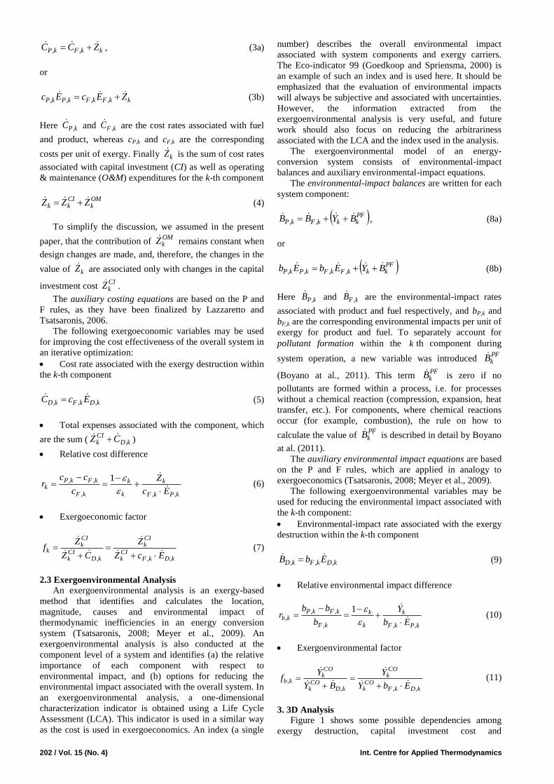
Table 3. Conventional exergetic analysis for the base case of the air refrigeration machine (Figure 1).
Component k,FE [kW] k,PE [kW] k,DE [kW] k [%] ky [%]
CM 801.20 687.90 113.30 85.9 25.3
EM 447.56 402.80 44.76 90.0 10.0
HE 109.10 12.24 96.86 11.2 21.6
EX 561.20 427.30 133.90 76.1 29.9
R 46.56 15.51 31.05 33.3 6.9
Overall system
( tot,LE = 12.24 kW) 447.6 15.51 419.90 3.5 93.7
Table 4. Values of selected exergoeconomic variables for the air refrigeration machine (base case).
Component kZ
[€/h]
k,DC
[€/h] kZ + k,DC
[€/h]
k,Fc
[€/MJ]
k,Pc
[€/MJ]
kr
[%]
kf
[%]
CM 2.44 39.98 42.42 0.098 0.115 17.5 5.8
EM 0.37 6.30 6.67 0.039 0.044 11.8 5.5
HE 1.54 40.16 41.70 0.115 1.062 821.7 3.7
EX 2.63 55.53 58.16 0.115 0.153 32.8 4.5
R 2.34 15.51 17.85 0.139 0.458 230.4 13.1
Overall
system
9.32 213.28 222.60 0.153 0.458 199.3 4.2
where cyclem is the mass flow rate of the working fluid (air)
through the compressor and expander, CM and EX are
the isentropic efficiencies of the compressor and the
expander, and UNCM and
UNEX are the isentropic efficiencies
corresponding to unavoidable exergy destruction for the
compressor and the expander (both assumed to be equal to
0.95). According to the concept of unavoidable exergy
destruction with a component, the PEC value at
unavoidable irreversibilities tends to infinity.
The equations for estimating the PEC for the heat
exchanger, and refrigerator are functions of the area of heat-
transfer surface (assuming that the overall heat-transfer
coefficient remains constant). For the electrical motor, PEC
depends on the required electric power:
Heat exchanger
603092
.HEHE APEC (14)
Refrigerator
603526
.RHE APEC (15)
Electrical motor
401697
.
EMEM WPEC (16)
The following data were used to calculate the capital
investment cost rates: Average cost of money ieff= 10%;
plant economic life n=15 years; average general inflation
rate rn=2.5%, and annual number of hours of system
operation at full capacity 7000 hours/year.
The cost balances and auxiliary equations for the
exergoeconomic model of the air refrigeration machine are
given in Table 2. Table 4 shows the data obtained from the
exergoeconomic analysis for the Base Case.
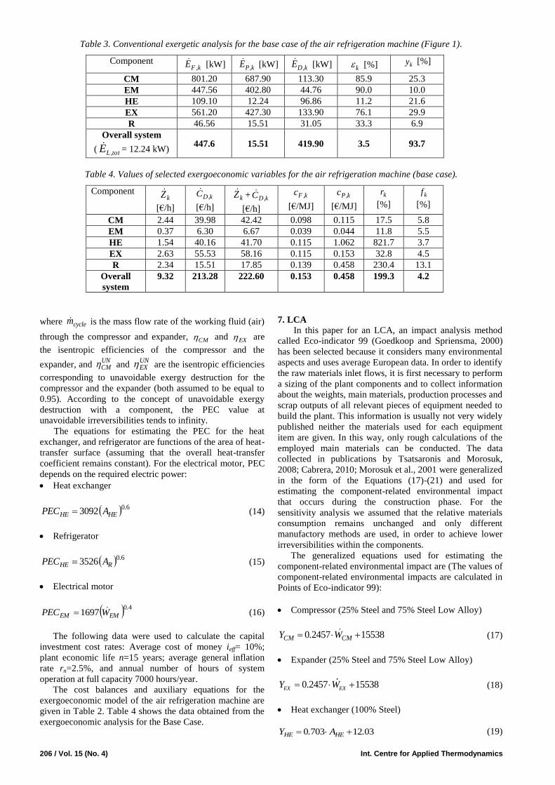
7. LCA
In this paper for an LCA, an impact analysis method
called Eco-indicator 99 (Goedkoop and Spriensma, 2000)
has been selected because it considers many environmental
aspects and uses average European data. In order to identify
the raw materials inlet flows, it is first necessary to perform
a sizing of the plant components and to collect information
about the weights, main materials, production processes and
scrap outputs of all relevant pieces of equipment needed to
build the plant. This information is usually not very widely
published neither the materials used for each equipment
item are given. In this way, only rough calculations of the
employed main materials can be conducted. The data
collected in publications by Tsatsaronis and Morosuk,
2008; Cabrera, 2010; Morosuk et al., 2001 were generalized
in the form of the Equations (17)-(21) and used for
estimating the component-related environmental impact
that occurs during the construction phase. For the
sensitivity analysis we assumed that the relative materials
consumption remains unchanged and only different
manufactory methods are used, in order to achieve lower
irreversibilities within the components.
The generalized equations used for estimating the
component-related environmental impact are (The values of
component-related environmental impacts are calculated in
Points of Eco-indicator 99):
Compressor (25% Steel and 75% Steel Low Alloy)
1553824570 CMCM W.Y (17)
Expander (25% Steel and 75% Steel Low Alloy)
0.2457 15538EX EXY W (18)
Heat exchanger (100% Steel)
03127030 .A.Y HEHE (19)
Int. J. of Thermodynamics Vol. 15 (No. 4) / 207
Refrigerator (25% Steel and 75% Steel Low Alloy)
9321223273811 .A.Y RR (20)
Electrical motor (40% Steel, 40% Steel Low Alloy, 20%
Cupper)
6701290
.
EMEM W.Y (21)
For these equations, the unit of power (W ) is kW and the
unit of heat –transfer surface ( A ) is m2.
The environmental impact of electricity is assumed to
be elb =27 mPts/kWh (Goedkoop and Spriensma, 2000).
The cost balances and auxiliary equations for the
exergoenvironmental model of the air refrigeration machine
are given in Table 2. Table 5 shows the data obtained from
the exergoenvironmental analysis for the Base Case.
8. 3D Analysis
Figures 3 and 4 show the results obtained from the
sensitivity exergetic, exergoeconomic and
exergoenvironmental analyses in the form of 3D diagram.
For this analysis we assumed:
The isentropic efficiency of the compressor is varied
between 75% and 94%,
The isentropic efficiency of the expander is varied
between 75% and 94%,
The minimal temperature difference within the heat
exchanger is varied between 3K and 15K,
The minimal temperature difference within the
refrigerator is varied between 3K and 25K,
The efficiency of the electrical motor remains constant.
Figure 3 shows the interdependencies among the
variables k,Pk,D E/E , k,PCIk E/Z and k,P
COk E/Y , while
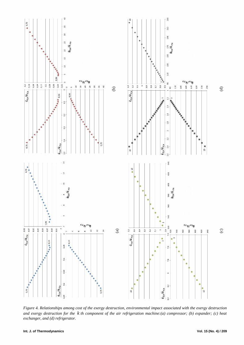
Figure 4 shows the interdependences among the variables
k,Pk,D E/E , k,Pk,D E/C (cost of the exergy destruction),
and k,Pk,D E/B (environmental impact associated with the
exergy destruction). Figure 5 summarizes the data from
Figures 3 and 5, i.e. shows the interdependencies among the
variables k,Pk,D E/E , k,Pkk,D E/ZC (total cost
associated with the k th component), and k,Pkk,D E/YB
(total environmental impact associated with the k th
component).
Figure 6 demonstrates the interdependencies among
total exergy destruction, cost and environmental impact of
the total product. For Figure 6 we selected only the data that
are lower than in the base case. This gives us an opportunity
to discuss the improvement of the overall system from the
thermodynamic, economic and environmental points of
view.
9. Results and discussions
Table 3 shows the results of the conventional exergetic
analysis of the air refrigeration machine. Based on the
values of k,DE we can conclude that the expander and the
compressor are the most important components from the
thermodynamic viewpoint. The improvement of the
evaporator cannot significantly affect the improvement of
the air refrigeration machine.
From the point of view of the advanced exergetic
analysis (theory and results have been reported by Morosuk
and Tsatsaronis, 2011a,b), the priority for the
thermodynamic improvement of the air refrigeration
machine is: Expander, refrigerator, compressor, and heat
exchanger. This priority was established by considering for
each component the sum of (a) the avoidable endogenous
exergy destruction, and (b) the total avoidable exogenous
exergy destruction caused by the component being
considered within the remaining components.
From the economic point of view (values of kZ ), the
turbomachines and the refrigerator are the most expensive
components. From the exergoeconomic point of view (sum
of kZ + k,DC ), the same components are very important.
The cost of the final product (cold) can be reduced by
reducing the cost of the exergy destruction ( k,DC ) within
all components. This can be achieved by decreasing the
exergy destruction within the components, because of the
relationship k,Dk,Fk,D EcC . For this refrigeration
machine we have a not very common situation, where
thermodynamic and cost improvements are obtained by the
same changes.
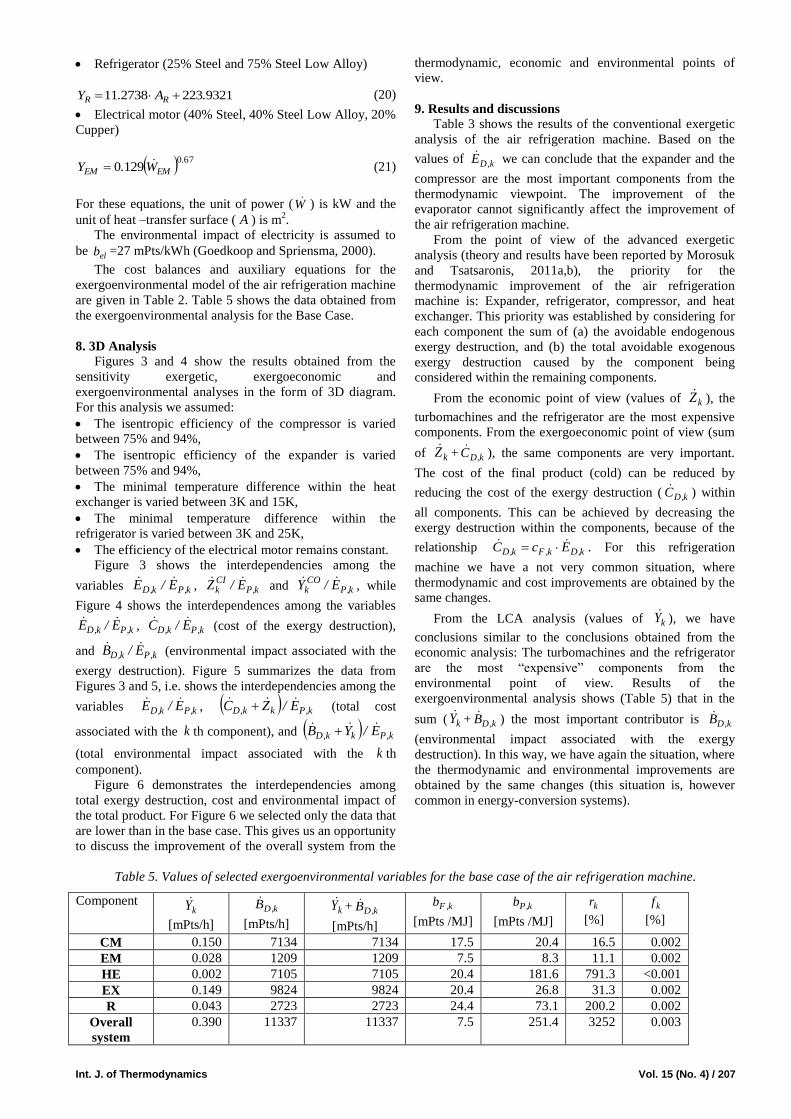
From the LCA analysis (values of kY ), we have
conclusions similar to the conclusions obtained from the
economic analysis: The turbomachines and the refrigerator
are the most “expensive” components from the
environmental point of view. Results of the
exergoenvironmental analysis shows (Table 5) that in the
sum ( kY + k,DB ) the most important contributor is k,DB
(environmental impact associated with the exergy
destruction). In this way, we have again the situation, where
the thermodynamic and environmental improvements are
obtained by the same changes (this situation is, however
common in energy-conversion systems).
Table 5. Values of selected exergoenvironmental variables for the base case of the air refrigeration machine.
Component kY
[mPts/h]
k,DB
[mPts/h] kY + k,DB
[mPts/h]
k,Fb
[mPts /MJ]
k,Pb
[mPts /MJ]
kr
[%]
kf
[%]
CM 0.150 7134 7134 17.5 20.4 16.5 0.002
EM 0.028 1209 1209 7.5 8.3 11.1 0.002
HE 0.002 7105 7105 20.4 181.6 791.3 <0.001
EX 0.149 9824 9824 20.4 26.8 31.3 0.002
R 0.043 2723 2723 24.4 73.1 200.2 0.002
Overall
system
0.390 11337 11337 7.5 251.4 3252 0.003

208 / Vol. 15 (No. 4) Int. Centre for Applied Thermodynamics
(b)
(d)
(a)
(c)
Figure 3. Relationships among capital investment, construction-of-component-related environmental impact and exergy
destruction for the k th component of the air refrigeration machine:(a) compressor; (b) expander; (c) heat exchanger, and
(d) refrigerator.
Int. J. of Thermodynamics Vol. 15 (No. 4) / 209
(b)
(d)
(a)
(c)
Figure 4. Relationships among cost of the exergy destruction, environmental impact associated with the exergy destruction
and exergy destruction for the k th component of the air refrigeration machine:(a) compressor; (b) expander; (c) heat
exchanger, and (d) refrigerator.

210 / Vol. 15 (No. 4) Int. Centre for Applied Thermodynamics
(b)
(d)
(a)
(c)
Figure 5. Relationships among total cost, total environmental impact and exergy destruction for the k th component of the
air refrigeration machine: (a) compressor; (b) expander; (c) heat exchanger, and (d) refrigerator.

Int. J. of Thermodynamics Vol. 15 (No. 4) / 211
Figure 6. Relationships among cost and environmental impact of the total product of the air refrigeration
machine and total exergy destruction.
The data obtained from the sensitivity analysis (Figure
3) show that the character of the three curves ( k,Pk,D E/E ,
k,PCIk E/Z and k,P
COk E/Y ) corresponds to the general case
(a) in Figure 1, but with different shapes. In this way, we
have the situation where lower values of k,Pk,D E/E
simultaneously correspond to lower values of k,PCIk E/Z
and of k,PCO
k E/Y .
Figure 4 shows that the interdependencies between
k,Pk,D E/E and k,Pk,D E/C as well as between k,Pk,D E/E
and k,Pk,D E/B have opposite behaviour. This provides the
opportunity that the total cost associated with the
component k,Pkk,D E/ZC and the total environmental
impact associated with the component could go through a
minimum value within the range of parameters variation
used for the sensitivity analysis. Figure 5 demonstrates that
this case exists only for the exergoeconomic variables of
the turbomachines. From Table 5 we already know that
variations in the value of kY cannot affect significantly the
sum kk,D YB .
In order to estimate the effect of irreversibilities within
the components to the overall thermodynamic, economic
and environmental characteristics of the air refrigeration
machine, the following three characteristics were analyzed
simultaneously: Total exergy destruction ( tot,DE ), specific
cost ( tot,Pc ) and specific environmental impact ( tot,Pb ) of
the product. For Figure 6 we selected the data that
correspond to the base case (Tables 3, 4 and 5) or lower
values that demonstrate the possibility for improving the
overall system. The following conclusions we can obtain
through the detailed analysis of the data shown in Figure 6:
For the air refrigeration machine, the thermodynamic
improvement of any of the components leads to a decrease
in the values of tot,DE and tot,Pb , i.e. to an improvement in
the total plant.
212 / Vol. 15 (No. 4) Int. Centre for Applied Thermodynamics
For the turbomachines the function tot,Pc has a
minimum, therefore the same value of tot,Pc corresponds to
the compressor and the expander with different efficiencies.
Within the range of tot,DE = 419.9 kW (base case) and
tot,DE ≈ 370 kW, the contribution of all components in
decreasing the value of tot,Pb is quite similar, whereas for
tot,DE < 370 kW we can see some differences. In the range
tot,DE = 419.9 kW to 370 kW the contribution of all
components (with the exception of compressor) in
decreasing the value of tot,Pc is also quite similar. In this
range of tot,DE values, the three components (expander,
heat exchanger and refrigerator) can lead to similar
improvements of the overall system.
If the total exergy destruction is lower than
approximately 370 kW, then only the expander and
refrigerator can contribute to improving the air refrigeration
machine. Note that improving the expander has a higher
effect on the thermodynamic, economic and LCA
characteristics of the overall air refrigeration machine than
improving the compressor.
Quarter III in Figure 6 clearly demonstrates that the
expander and the refrigerator have a higher potential for
simultaneously decreasing cost and environmental impact
of the overall product.
The last conclusion obtained from the 3D sensitivity
analysis fully confirms the conclusions obtained from the
advanced exergetic analysis conducted for the same
refrigeration machine (Morosuk and Tsatsaronis, 2011a,b).
10. Conclusions
A relatively simple energy-conversion system (without
a chemical reaction) was used in this paper to study the
interdependencies among costs, environmental impacts and
thermodynamic inefficiencies. The results demonstrate that
in an air refrigeration machine, improvements in efficiency
result, in general, to decreases in both costs and
environmental impacts. The detailed sensitivity analysis
fully confirms findings obtained through advanced exergy-
based analyses. The analysis presented here suggests ways
for improving an energy-conversion system simultaneously
from a thermodynamic, economic and ecological viewpoint.
Nomenclature
B environmental impact associated with an exergy stream
[Points]
b environmental impact per unit of exergy [Points/J]
C cost associated with an exergy stream [€]
c cost per unit of exergy [€/J]
E exergy [J]
e specific exergy [J/kg]
f exergoeconomic factor [-]
k k th component [-]
m mass [kg]
p pressure [Pa]
r relative cost difference [%]
T temperature [K]
Y construction-of-component-related environmental
impact [Points]
y exergy destruction ratio [-]
Z cost associated with investment expenditures [€]
Greek symbols
exergetic efficiency [%]
isentropic efficiency [%]
Subscripts
b refers to environmental impact
D refers to exergy destruction
F fuel
P product
tot refers to the total system
Y refers to construction-of-component-related
environmental impact
Z refers to investment costs
References
Bejan A., Tsatsaronis G., Moran M., 1996, Thermal Design
and Optimization, Wiley, New York.
Boyano A., Blanco-Marigorta A.M., Morosuk T.,
Tsatsaronis G., 2011, Exergoenvironmental analysis of
a steam methane reforming process for hydrogen
production. Energy Int. J., Vol.36 (4), pp. 2202-2214.
Cabrera Cabrera M. Exergoenvironmental Analysis of
Oxyfuel-based Combined-Cycle Power Plants including
CO2 Capture, Master Thesis, Technische Universität
Berlin, 2010.
Goedkoop M., Spriensma R., 2000, The Eco-indicator 99:
A damage oriented method for Life Cycle Impact
Assessment. Methodology Report. Amersfoort,
Netherlands, (http:\\www.pre.nl).
Kakac S., Liu H., 1998, Heat exchangers: Selection, rating,
and thermal design. CRC Press LLC.
Lazzaretto A., Tsatsaronis G., 2006, SPECO: A systematic
and general methodology for calculating efficiencies
and costs in thermal systems, Energy – The
International Journal, Vol. 31, pp. 1257-1289.
Meyer L., Tsatsaronis G., Buchgeister J. and Schebek L.,
2009, Exergoenvironmental Analysis for Evaluation of
the Environmental Impact of Energy Conversion
Systems, Energy Int. J., Vol. 34, 2009, pp. 75-89.
Morosuk T., Tsatsaronis G., 2005, Graphical models for
splitting physical exergy. Proceedings of ECOS-2005
“Shaping our future energy systems”, Kjelstrup, S.,
Hustad, J.E., Gundersen, T., Rosjorde, A. and
Tsatsaronis, G., eds., 1, pp. 377-384.
Morosuk T., Tsatsaronis G., 2011, Advanced
exergoeconomic analysis of a refrigeration machine:
Part 1. Methodology and first evaluation. Proceedings
of the ASME 2011 International Mechanical
Engineering Congress & Exposition (IMECE2011),
November 11-17, 2011, Denver, Colorado, USA, CD-
ROM, file IMECE2011-62688.
Morosuk T., Tsatsaronis G., 2011, Advanced
exergoeconomic analysis of a refrigeration machine:
Part 2. Improvement. Proceedings of the ASME 2011
International Mechanical Engineering Congress &
Exposition (IMECE2011), November 11-17, 2011,

Int. J. of Thermodynamics Vol. 15 (No. 4) / 213
Denver, Colorado, USA, CD-ROM, file IMECE2011-
62689.
Morosuk T., Tsatsaronis G., Boyano A., Gantiva C., 2012,
Advanced exergy-based analyses applied to a system
including LNG regasification and electricity generation.
International Journal of Energy and Environmental
Engineering (A Springer Open Journal -
http://www.journal-ijeee.com/content/3/1/1), 3:1, 9 p.
Tsatsaronis G., 1984, Combination of Exergetic and
Economic Analysis in Energy-Conversion Processes. In:
Energy Economics and Management in Industry,
Proceedings of the European Congress, Algarve,
Portugal, April 2-5, 1984, England, Oxford: Pergamon
Press, Vol. 1, pp. 151-157.
Tsatsaronis G., 2008, Recent developments in exergy
analysis and exergoeconomics, Int. J. Exergy, Vol. 5,
Nos. 5/6, pp.489–499.
Tsatsaronis G., Morosuk T., 2008, A general exergy-based
method for combining a cost analysis with an
environmental impact analysis. Proceedings of the
ASME International Mechanical Engineering Congress
and Exposition, Boston, USA, 2008, files IMECE2008-
67218 and IMECE2008-67219.