3 car carrier operations and maintenance manual … · 3 car carrier operations and maintenance...
TRANSCRIPT

3 CAR CARRIER
OPERATIONS AND MAINTENANCEMANUAL
13224 Fountainhead PlazaHagerstown, MD 21742 Phone (717) 597-7111 www.jerr-dan.com

FOREWORD
This manual is intended to serve as a guide to the owner and operatorin the safe operation and optimum performance of this Jerr-Dan equip-ment.
Establishment of good operating habits and familiarity with the equip-ment and its capabilities combined with good judgement are essential.
Before attempting to operate the unit carefully read all sections of thismanual.

Rev. __________
Date _________
TABLE OF CONTENTS
Certification ...................................................................................... 0.1
Safety ............................................................................................... 1.1Decal Group ..................................................................................... 1.5
Operation .......................................................................................... 2.1
Maintenance and Lubrication ........................................................... 3.1Lubrication Chart .............................................................................. 3.3Troubleshooting ................................................................................ 3.4
1
9/14

Rev. __________
Date _________
THIS PAGE INTENTIONALLY LEFT BLANK

Rev. __________
Date _________0.1
NOTICE
MANUFACTURED BY:
DATE OF MANUFACTURE_____mo. _____yr.
INCOMPLETE VEHICLE MANUFACTUREDBY:
DATE INC. VEH. MFD. _____mo._____yr.
GVWR _______________________________
GAWR FRONT _____________________ with__________________________________tires,_____ rims, @ _____ psi cold _____________
GAWR INTERMEDIATE (1) ____________with__________________________________tires,_____ rims, @ _____ psi cold _____________
GAWR INTERMEDIATE (2) ____________with__________________________________tires,_____ rims, @ _____ psi cold _____________
GAWR REAR ______________________with__________________________________tires,_____ rims, @ _____ psi cold _____________
Conformity of the chassis-cab to Federal MotorVehicle Safety Standards, which have beenpreviously fully certified by the incomplete vehiclemanufacturer or intermediate vehicle manufacture,has not been affected by final-stage manufacture.The vehicle has been completed in accordancewith the prior manufacturer’s instructions, whereapplicable. This vehicle conforms to all otherapplicable Federal Motor Vehicle Safety Standardsin effect in:
_____mo._____yr.
VEHICLE IDENTIFICATION NUMBER:
VEHICLE TYPE: ________________________
This certification sticker appears on every Jerr-Dan unit mounted on a new chassis andis required by law. Jerr-Dan Corporation will not certify any unit for a capacity greater thanthe chassis manufacturer’s specified rating. The capacity ratings of Jerr-Dan units donot imply that vehicles can be used without regard to gross vehicle weight ratings(GVWR) or gross axle rating limitations.
The payload carrying capacity of any truck is determined by the GVWR of the cabchassis, the curb weight of the cab chassis and the weight of the body. It is important thatyou determine that your truck has satisfactory carrying capacity and axle ratings for yourspecific application. Jerr-Dan’s authorized sales representatives are available to assistyou in this regard.

Rev. __________
Date _________0.2
THIS PAGE INTENTIONALLY LEFT BLANK

Rev. __________
Date _________1.1
SAFETY
Safety is all-important when working with machinery. Accidents happenwhen established safety practices have been overlooked.
Read and practice all safety points listed in this manual. Safety is theprime responsibility of the operator.
1. Read operating and loading instructions thoroughly.
2. Become familiar with the loads that your unit can safely transportwithout exceeding the structural capacity of the Jerr-Dan equipmentor the gross axle weight ratings, gross vehicle weight rating, andgross combined vehicle weight rating of your chassis.
3. Observe all warning decals.
4. Make sure you are clear of oncoming traffic. Dual controls (driver’sside and passenger’s side) are standard on your Jerr-Dan roll back.
5. Always put bumper on the ground to support the body and truckframe.
6. Never exceed the rated capacity of the body or truck chassis andit’s components or use a tow option without a vehicle on the deck.

Rev. __________
Date _________1.2
7. Never winch from the side of the bed. Winch only from the rearwith load in line with the winch. Failure to do so can result in winchor wire rope damage. JERR-DAN DOES NOT RECOMMEND THEUSE OF SIDE PULLING DEVICES.
8. Always try to winch from the center of the load.
9. Maintain winch cable in good condition. Replace when worn, kinkedor frayed. Do not use cable clamps.

Rev. __________
Date _________1.3
10. When loading or unloading the deck and operating the winch, makecertain the area behind the load is clear of personnel and obstacles.
11. Distribute load evenly on the deck. Do not concentrate the load onone section of the deck, to the rear of the truck axles, or use a towoption without a load on the deck.
12. Secure cargo to the deck at both the front and rear before the truckis driven. Do not rely on the winch as the only means of holdingthe load.

Rev. __________
Date _________1.4
13. Keep alert. Do not be distracted during any operating sequences.
14. Do not work behind truck with vehicle on deck unless vehicle issecured at front of deck. (Do not rely on winch.)
15. Read and follow wheel lift instructions for proper towing.
16. Do not exceed tow option ratings. Overloading can cause unsafesteering and braking conditions.
17. Always use both wheel straps on wheel lift.
18. Use separate safety chains from towed vehicle to subframe for towoptions. Always attach safety chains to the opposite side of theattaching point, crossing chains under the tow option. Allow enoughslack in the chains to maneuver around corners without binding.
19. Insure deck is in the locked position before traveling.
20. Review operator’s pre-transport checklist located on the headboardof the deck each time you move a vehicle.
21. Block up deck before performing any service or maintenance workunder deck.

Rev. __________
Date _________1.5
DECAL GROUP
(STANDARD DECAL, LEFT SIDE)
(STANDARD DECAL, RIGHT SIDE)
(LUBRICATION CHART)
1
9/14

Rev. __________
Date _________1.6
(WINCH)
CAUTIONCAUTIONMAINTAIN OIL LEVEL WITHIN 1/2" OF
TOP OF SIGHT GAUGE WITH ALL
CYLINDERS FULLY RETRACTED. TORQUE
SIGHT GAUGE BOLTS: 8 FT-LBS MAX.272-02
(HYDRAULIC OIL LEVEL)
OTHER PATENTS PENDING
UNDER ONE OR MORE OFTHE FOLLOWING PATENTS:
5,133,633 5,575,6065,697,741 5,722,810
6,315,515 B1 6,336,783 B16,447,239 B2 7,264,305 B2
5,951,235 6,231,294 B1
1001132766-A
FOR:
MANUFACTURED BY: JLG INDUSTRIES, INC.
IDENT. NO.MODEL
VERSION
(SUBFRAME ID) (SERIAL NUMBER)
SERIAL NO.
MODEL NO.
MANUF ACTURED BY :JL G I NDUSTRIES, INC.
1001127221-00
FOR:
1
9/14

Rev. __________
Date _________1.7
SLIDE DECK UNTILSLIDE DECK UNTIL
ARROW ALIGNS WITHARROW ALIGNS WITH
FIRST LEVERFIRST LEVER
BEFORE TILITINGBEFORE TILITING
(DECK ALIGNMENT)
(TOW OPTION WARNING)
(WHEEL LIFT WARNING)

Rev. __________
Date _________1.8
CAUTIONCAUTION
165
FULLY RETRACT TOW OPTION
BOOM TO AVOID DAMAGE
DURING OPERATION OF OTHER
CARRIER FUNCTIONS.
(TOW OPTION WARNING)
(CHECKLIST REMINDER)

Rev. __________
Date _________1.9
(CHECKLIST)

Rev. __________
Date _________1.10
WARNING
LOCATED UNDER MAIN DECK
WINCH FREE SPOOL SYSTEM
WINCH TO LATCH IN.THEN RELEASE. OPERATETO ENGAGE: LIFT UP KNOB
GUIDE BUSHING POSITIONED AS SHOWNMUST BE COMPLETELY ENGAGED WITHBEFORE OPERATION - WINCH CLUTCH
OUT. LOCK IN PLACE.UP KNOB AND PULL TO DISENGAGE: LIFT
381
(FREE-SPOOL OPERATION)
(SLIDE PAD LUBRICATION)
REMOVING DECK FROM SUBFRAME.REMOVE ORBIT MOTOR FITTINGS PRIOR TO
COMPLETELY ONTO SUBFRAME.
INTO ORBIT MOTOR TILL DECK IS SLIDDO NOT INSTALL ORBIT MOTOR FITTINGS
INSTALLATION AND REMOVAL OF DECK.
WITH NYLON CABLE TRACK SYSTEM UPON WINCH ORBIT MOTOR FITTINGS WILL INTERFERE
WARNING
330
(ORBIT MOTOR FITTINGS WARNING)

Rev. __________
Date _________1.11
MODELNUMBER:SERIAL NUMBER:
MAIN DECK CAPACITY: LBS.*
DO NOT EXCEED THE ABOVE STRUCTURAL RATINGS.
THE MAXIMUM EFFECTIVE TRANSPORT LOADMAY BE LIMITED BY THE GAWR, GVWR OR GCWR
OF THE TRUCK CHASSIS.
THE MAXIMUM EFFECTIVE TRANSPORT LOAD MAY BELIMITED BY THE RATINGS OF ANY TOW IMPLEMENTS,
ATTACHMENTS, OR ACCESSORIES BEING USED.
WHEN SUPPLIED, THE SAFETY LOCKING PINMUST BE IN PLACE DURING TRANSPORT TO
ACHIEVE THE RATINGS LISTED ABOVE.
SAFETY IS NO ACCIDENT. REVIEW OPERATOR'SPRE-TRANSPORT CHECKLIST ON VEHICLE AND IN THEOWNERS MANUAL EACH TIME YOU MOVE A VEHICLE.
FOLLOW ALL INSTRUCTIONS ON CONTROLS AND UNIT.
UPPER DECK CAPACITY: LBS.*
WHEELLIFT/TOWBAR LIFT CAPACITY:(FULL EXTENSION)
STRUCTURAL CAPACITIES*
LBS.*
WHEELLIFT/TOWBAR TOW CAPACITY:
LBS.*
HITCH OPTION TONGUE CAPACITY:(FULL RETRACTION)
LBS.*
*PLEASE READ THE FOLLOWING INORDER TO ENSURE SAFE AND
CORRECT USE OF THE EQUIPMENT.
HITCH OPTION TONGUE CAPACITY:
LBS.*
1001132765-A
13224 Fountainhead PlazaHagerstown, MD 21742Phone (717) 597-7111
www.jerr-dan.com
FOR:
MANUFACTURED BY: JLG INDUSTRIES, INC.
(STRUCTURAL RATING PLACARD)
1
9/14

Rev. __________
Date _________1.12
THIS PAGE INTENTIONALLY LEFT BLANK

Rev. __________
Date _________2.1
OPERATION
A. Controls
The operating controls for the Jerr-Dan equipment are conveniently locatedon both the driver’s and passenger’s side.
All operators must be trained and understand the contents of the operator’smanual before operating any controls.
Assure adequate operating clearance and the safety of all personnel be-fore operating the rollback equipment.
The following controls are provided:1. Power-take-off (in truck cab)2. Auxiliary engine throttle control
(in truck cab)3. Rollback control (first handle in control
station)4. Tilt control, lower deck (second handle in control station)5. Winch control, lower deck front winch (third handle in control
station)6. Winch control, lower deck rear winch (fourth handle in control
station)7. Tilt control, upper deck (fifth handle in control station)8. Winch control, upper deck (sixth handle in control station)9. Tow option/Stabilizer, up/down (seventh handle in control
station)10. Tow option, in/out (eigth handle in control station)
B. Loading the Deck
1. PositionPark the truck with the rear of the deck approximately 12 feet from theobject to be loaded and in line with that object.
CAUTION: The unit should always be loaded and unloaded on leveland stable ground.
109
87
65
43
T
P
O
L
L
O
R
T
L
I
T
H
C
N
I
W
H
C
N
I
W
T
L
I
T
H
C
N
I
W
L
I
B
A
T
S
R
A
B
W
O
T
W
O
T
ASSURE PROPER MAINTENANCE.
OR DEFECTIVE.DO NOT OPERATE IF DAMAGED
ENGAGING TRANSMISSION.DISENGAGE PTO BEFORE
UNIFORMLY DISTRIBUTED.CAPACITY LOADS MUST BE
COMPLY WITH ALL LOAD RATINGS.
ADEQUATELY SECURE ALL LOADS.
TO TOWED VEHICLE.USE SAFETY CHAINS FROM SUBFRAME
TILT ONLY WHEN DECAL ALIGNS WITH
ASSURE SAFETY OF ALL PERSONNEL.
FIRST CONTROL HANDLE.
ASSURE ENGAGEMENT OF WINCH DRUM.
UNDERSTAND THE OPERATOR'S MANUAL.
ALL OPERATORS SHOULD BE TRAINED AND
OPERATING INSTRUCTIONS
343
12 FT.1

Rev. __________
Date _________2.2
1a. Set the parking brake.1b. With the engine running, engage the PTO per instructions in the
truck cab or in the PTO Operating Manual.1c. Set the auxiliary throttle. After operating the unit several times,
one will establish a feel for the optimum speed. DO NOTOVERSPEED.
2. RollRaise the rollback handle and the deck will slide back. Roll the deck rear-ward approximately 12 inches to clear the mechanical hold downs at thefront of the frame. A decal is provided on the rubrail to aid in determiningthe amount to roll. Align the decal pointer with the roll (first) control handle.
3. TiltRaise the tilt control lever, raising the forward end of the deck until the rearbumper rests firmly on the ground.
4. RollRaise the roll handle and the deck will slide back. Continue this operationuntil the approach plate of the deck has contacted the ground. Make surethat the rear bumper and the approach plate are both in firm contact withthe ground before loading. There should be an equal weight distributionbetween the rear bumper and the end of the deck.
5. WinchWinch the load onto the deck. Refer to the Winch Operation Manual forspecific winch operation procedures.
SLIDE DECK UNTILSLIDE DECK UNTIL
ARROW ALIGNS WITHARROW ALIGNS WITH
FIRST LEVERFIRST LEVER
BEFORE TILITINGBEFORE TILITING
2
4
5
3

Rev. __________
Date _________2.3
5a. Raise the winch control handle to power unreel the winch cable while asecond person keeps the cable taut or disengages the winch clutchand free spool the cable. (See the Winch Operation Manual for properclutch disengagement prodecures)
5b. Engage the winch clutch if the winch cable was free spooled. Raise thewinch handle (unreel the cable)until the winch clutch fully engages.Ensure that the winch clutch is fully engaged before putting a load onthe winch.
5c. Attach the winch cable to the load. The winch cable should be attachedas close to the center of the load as possible. It may be necessary touse a “V” chain or other implement to attach the winch cable to the load.
5d. Lower the Winch control handle to wind the cable onto the winch drumand pull the load onto the deck.
CAUTION: Never disengage the winch clutch when the winch isunder load.
CAUTION: Always maintain a minimum of 5 wraps of cable on thewinch drum.
CAUTION: Always winch load onto deck, NEVER drive equipmentonto the tilted deck.
CAUTION: Always maintain a uniform wrap of cable on the drum.“Nesting” of the winch cable may cause damage or pre-mature wear of the winch cable.
CAUTION: Remember that cables break, winches fail, and hooks be-come disengaged. DO NOT WORK BELOW THE LOAD!
CAUTION: Replace worn or damaged cables. Always wear gloveswhen handling cable. DO NOT USE CABLE CLAMPS.
CAUTION: The winch cable should remain attached to the load andtaut.
6. Secure LoadOnce the load is positioned on the deck secure it from movement in alldirections. Set the parking brake or use wheel chocks if applicable.

Rev. __________
Date _________2.4
7. RollLower the roll control handle to roll the deck forward until the deck is in theproper position for tilting. The deck is in the proper position for tilting whenthe decal pointer is aligned with or just behind the roll (first) control handle.
8. TiltLower the tilt control handle to lower the front of the deck until the decklays flat on the slide pads on the hold down.NOTE: Tilting deck when fully forward will cause damage to the holddowns.
9. RollLower the roll control handle to roll the deck forward until it is in the fullforward position and under the hold downs.
10. Secure LoadAll loads must be secured from movement in all directions using safety tie-downs. Jerr-Dan provides straps and chains suitable for securing mostvehicles to the deck. Vehicles should be secured at all four corners usingsafety tie-downs. Set brakes (if a vehicle) and use wheel blocks and tie-downs for safe transport. Refer to the AAA or vehicle manufacturerstowing manual for correct attachment points.
CAUTION: Use safety tie-downs to secure the load against rearwardmotion. Leave the winch cable attatched to the load andtaut, but do not rely on the winch cable to secure the load.
11. Disconnect PTOReturn the engine to normal idle speed and disengage the PTO beforeengaging the transmission. Driving the truck with the PTO engaged willcause overspeeding. Overspeeding of the PTO and/or pump will greatlyshorten their life and can cause damage to the PTO, pump, and transmis-sion.
7
8
9

Rev. __________
Date _________2.5
C. Unloading the Deck
1. PositionPark the truck with the rear of the deck approximately 12 feet from desiredposition of vehicle being unloaded.
1a. Set the parking brake.1b. With the engine running, engage the PTO per instructions in the
truck cab.1c. Set the auxiliary throttle. After operating the unit several times
one will establish a feel for the optimum speed. DO NOTOVERSPEED.
1d. Partially release bindings of the load but maintain restraint againstmovement of the load in any direction.
2. RollRaise the rollback handle and the deck will slide back. Roll the deck rear-ward approximately 12 inches to clear the mechanical hold downs at thefront of the frame. A decal is provided on the rubrail to aid in determiningthe amount to roll. Align the decal pointer with the roll (first) control handle.
3. TiltRaise the tilt control handle, raising the forward end of the deck until therear bumper rests firmly on the ground.
LENGTH12'+1
2 SLIDE DECK UNTILSLIDE DECK UNTIL
ARROW ALIGNS WITHARROW ALIGNS WITH
FIRST LEVERFIRST LEVER
BEFORE TILITINGBEFORE TILITING
3

Rev. __________
Date _________2.6
4. RollRaise the roll handle and the deck will slide back. Continue this operationuntil the approach plate has contacted the ground.Make sure that the rearbumper and the approach plate are both in firm contact with the groundbefore unloading. There should be an equal weight distribution betweenthe rear bumper and the end of the deck.
5. WinchWinch the load off of the deck. Refer to the Winch Operation Manual forspecific winch operation procedures.
5a. Ensure that the winch cable is securely attached to theload and is taut. Ensure that the winch clutch is fullyengaged (the winch is NOT in free spool mode.)
5b. Remove all equipment used to secure the load to the deck(excluding the winch cable). Release brakes of the load (ifapplicable).
5c. Raise the winch control to power unreel the cable from thedrum, lowering the load from the deck.
5d. Secure the load on the ground Remove the winch cablefrom the lod and store the cable.
CAUTION: Never disengage the winch clutch when the winch isunder load.
CAUTION: Always maintain a minimum of 5 wraps of cable on thewinch drum.
CAUTION: Always winch load off of the deck, NEVER drive equip-ment on the tilted deck.
4
5

Rev. __________
Date _________2.7
CAUTION: Always maintain a uniform wrap of cable on the drum.“Nesting” of the winch cable may cause damager or pre-mature wear of the winch cable.
CAUTION: Remember that cables break,winches fail,and hooks be-come disengaged. DON’T WORK BELOW THE LOAD!
CAUTION: Replace worn or damaged cables. Always wear gloveswhen handling cable. DO NOT USE CABLE CLAMPS!
D. LOADING THE OVERCAB DECK
1. POSITIONPosition the truck with the rear of the deck approximately 12 feet from theobject to be loaded and in line with that object.
CAUTION: The unit should always be loaded and unloaded on leveland stable ground.
1a. Set the parking brake.1b. With the engine running, engage the PTO per instructions in the
truck cab or in the PTO Operating Manual.1c. Set the auxiliary throttle. After operating the unit several times,
one will establish a feel for the optimum speed. DO NOTOVERSPEED.
2. RollRaise the rollback handle (first lever) and the deck will slide back. Roll thedeck rearward approximately 12 inches to clear the mechanical hold downsat the front of the frame. A decal is provided on the rubrail to aid in deter-mining the amount to roll. Align the decal pointer with the roll (first) controlhandle.
12 FT.1
2 SLIDE DECK UNTILSLIDE DECK UNTIL
ARROW ALIGNS WITHARROW ALIGNS WITH
FIRST LEVERFIRST LEVER
BEFORE TILITINGBEFORE TILITING
Rev. __________
Date _________2.8
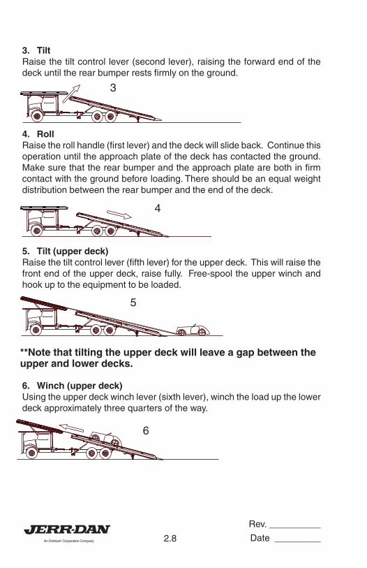
3. TiltRaise the tilt control lever (second lever), raising the forward end of thedeck until the rear bumper rests firmly on the ground.
4. RollRaise the roll handle (first lever) and the deck will slide back. Continue thisoperation until the approach plate of the deck has contacted the ground.Make sure that the rear bumper and the approach plate are both in firmcontact with the ground before loading. There should be an equal weightdistribution between the rear bumper and the end of the deck.
5. Tilt (upper deck)Raise the tilt control lever (fifth lever) for the upper deck. This will raise thefront end of the upper deck, raise fully. Free-spool the upper winch andhook up to the equipment to be loaded.
**Note that tilting the upper deck will leave a gap between theupper and lower decks.
6. Winch (upper deck)Using the upper deck winch lever (sixth lever), winch the load up the lowerdeck approximately three quarters of the way.
3
4
6
5
Rev. __________
Date _________2.9
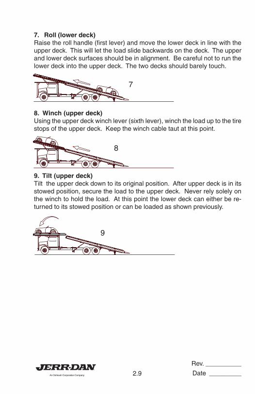
7. Roll (lower deck)Raise the roll handle (first lever) and move the lower deck in line with theupper deck. This will let the load slide backwards on the deck. The upperand lower deck surfaces should be in alignment. Be careful not to run thelower deck into the upper deck. The two decks should barely touch.
8. Winch (upper deck)Using the upper deck winch lever (sixth lever), winch the load up to the tirestops of the upper deck. Keep the winch cable taut at this point.
9. Tilt (upper deck)Tilt the upper deck down to its original position. After upper deck is in itsstowed position, secure the load to the upper deck. Never rely solely onthe winch to hold the load. At this point the lower deck can either be re-turned to its stowed position or can be loaded as shown previously.
7
8
9

Rev. __________
Date _________2.10
E. Unloading (upper deck)
Note: The main deck should be empty prior to unloading the topdeck.
1. TiltingTilt the upper deck and the lower deck into alignment. Assure that theupper deck winch cable is taut. Be sure that the load is partially unsecuredprior to titlitng, but maintain restraint against movement in every direction.
2. Winch (upper deck)Release the remaining bindings, except for the winch cable. Winch theload down onto the main deck until it it centered about half way on the maindeck.
3. Roll, Tilt, and WinchRoll and tilt the lower deck until the approach tip and the bumper tubes arefirmly on the ground. Using the upper winch control, winch the load safelyto the ground. Block the vehicle or apply the emergency brake after theload is safely on the ground.
4. FinishFinish the process by winching the cable back onto the upper deck winch.Then tilt the upper deck back into it’s stowed position. Proceed to do thesame process with the lower deck. Be sure that all chains, binders etc. aresecured in a toolbox prior to driving. Be sure that the pto is disengagedprior to driving, as this may cause damage to the PTO.
1
2
3

Rev. __________
Date _________2.11
F. Operation of the Wheel Lift (Option)
The wheel lift allows an additional vehicle to be towed damage free on itsown suspension by utilizing a wheel grid similar to the Jerr-Dan HPL wheellift. The wheel lift cross bar may also be used as a conventional tow bar forbadly damaged or heavier vehicles.
CAUTION: Because of the additional boom extension and load point of thetowed vehicle, the wheel lift places more load on the rear axleand unloads the front axle more than a conventional tow bar.Overloading the wheel lift may result in unsafe steering andbraking conditions and may damage the truck frame. Also,never use the wheel lift without a vehicle on the deck. Singlevehicle transport should utilize the deck.
1. Position the truck within three (3)to four (4) feet of the subject ve-hicle and as close to the direc-tion of the pull as possible.
2a. Set the parking brake.
2b. With the engine running, engagethe PTO per instructions in thetruck cab or in the PTO Operat-ing Manual.
2c. Set the auxiliary throttle. Afteroperating the unit several times,one will establish a feel for theoptimum speed. DO NOTOVERSPEED.
Be sure the towed vehicle isnot in gear or park. Keep thebrake set.
3. Lower the wheel lift arm to about1-1/2 inches from the groundand swing the cross bar paral-lel to the tires.

Rev. __________
Date _________2.12
4. Set the grid width as required forthe vehicle to be towed. Be sureboth grids are as close to thecenter of the boom as possible.
5. To set the grid width, loosen the“T” handles on the front of thegrid arms and pull the grids out.Be sure both grids are as closeto the center of the boom as pos-sible, and wide enough to allowthe “L” arms to slide into theirchannels. Tighten the “T”handles to secure the grids.
6. Retract the “Cam” handle lock-ing pin on the grid by turning it ahalf turn. It should remain in theopen position.
7. Extend the lift arm under the ve-hicle being sure that all undercarriage parts are cleared andthat the front portion of the gridis in contact with both tires.Lower the grid fully to theground. There is no reason forthe operator to get under thevehicle.
8. Visually inspect the tire to gridcontact before proceeding.
9. Take the “L” arms and slide theminto the channels on the side ofthe grid. Insure that they areresting snugly against the tires,with the “L” arms in close con-tact with the tires, reset the lock-ing pin by turning the “Cam”handle back to the original posi-tion. Be sure that the pin seatsin one of the holes. The tiresare now confined front and back.

Rev. __________
Date _________2.13
10. After securing the grid armaround the towed vehicles tiresand before making the actual lift,check to be sure the towedvehicle’s parking brake is re-leased, the transmission is inneutral, and the wheels arestraight.
NOTE: If vehicle to be towed is ona slope, do not release thebrake until the tie-downstraps are installed. Ob-serve the wheels in the gridfor any slippage.
11. It is recommended that thesteering wheel of the towed ve-hicle be secured in the straightposition by a steering wheelstrap for any tow.
12. Lift the vehicle high enough toallow the tires to clear ground.
13. Remove the tie-down strapsfrom toolboxes and attach thetie-down straps. (See the follow-ing section on the tie-downstraps.)
14. With the straps in place, the ve-hicle in neutral and the parkingbrake released, you can movethe vehicle safely up, down, inor out. All of these movementsare hydraulically controlled.

Rev. __________
Date _________2.14
15. Raise the vehicle into the finaltowing position observing the farend for sufficient ground clear-ance. It is possible to set therear of a front lifted vehicle com-pletely onto the ground, causingdamage. Take irregular road-surfaces into consideration.Observe the lift function from theside and away from both ve-hicles if possible. Make sure thatthere are no under body com-ponents of the towed vehicle incontact with the “L” arms orwheel grid device. Readjust ifnecessary.
16. Power retract the grid boom un-til the towed vehicle is aboutthree (3) to four (4) feet from theback of the truck. Leave enoughroom to maneuver around cor-ners without corner binding orcausing contact between the two(2) vehicles. Be sure that theboom is extended at least 4inches to insure unobstructedcrossbar pivoting.
17. Be sure to maintain sufficientclearances with the bottom ofthe towed vehicle.
18. Attach the safety chains andmagnetic towing lights. SAFETYCHAINS MUST BE CROSSED.
CAUTION: Always tow with the tow bar extended so that adequate
clearance is maintained between deck and towed vehicle.
CAUTION: Properly secure the vehicle being towed. Use separate
safety chains from towed vehicle to carrier subframe.

Rev. __________
Date _________2.15
CAUTION: After unloading the vehicle being towed, fully retract the
wheel lift before tilting or rolling the deck.
CAUTION: When not in use, wheel lift must be in upper position and
fully retracted.
CAUTION: The wheel lift option is designed for the transport of an
additional vehicle only. Under no circumstances should avehicle be transported on the wheel lift without a vehicleon the deck as it may cause unsafe steering and brakingconditions. Single vehicle transport should utilize the deck.
CAUTION: When not in use, wheel lift “L” arms must be stored in the
storage tubes provided on the carrier subframe. “L” armsshould never be stored in the wheel grids when not in use.

Rev. __________
Date _________2.16
TIE-DOWN STRAPS
Your carrier is supplied with a set of high strength polyester web tie-downstraps. They are to be used to secure wheels of the towed vehicle to thewheel lift grid. NEVER TOW A VEHICLE WITHOUT THE TIE-DOWNSTRAPS INSTALLED.
The tie-down strap assembly iscomprised of two (2) basic compo-nents:1. The strap2. The ratchet spool mechanism
The following steps should befollowed to properly install the tie-down straps:
USING THE RATCHET SPOOL MECHANISM
1. First the spool must be set into“free spool”. This is done by pull-ing the lock bar out and swing-ing the handle upward until itrests in the free spool notch andthen simply pulling out theamount of strap required to fitover the tire.
2. Now pull on the lock bar andmove it downward until it en-gages the ratchet teeth on thetake up spool. By pushing andpulling the handle up and down,the strap will be wound onto thespool.
3. To release the ratchet, simplypull on the locking bar, disengag-ing the teeth and raise thehandle to the “free spool” posi-tion.

Rev. __________
Date _________2.17
INSTALLING THE TIE-DOWN STRAP
1. With the vehicle lifted just barelyoff the ground, attach the strapto the wheel grid. Be sure thehook on the ratchet is securelyseated in the “L” arm.
2. Set the ratchet spool in “freespool” position and pull thewebbed strap out and form aloop which will wrap around thetire. Be sure the loop is over aminimum of 1/3 of the tire.
3. Take up the slack in the strap byratcheting the takeup spool arm.Continue until the tires showsome compression.
4. Raise the wheel grid to the tow-ing position. RE-TIGHTEN THERATCHET PERIODICALLY ASTIRE SETTLES IN GRID FROMTOWING.

Rev. __________
Date _________2.18
THIS PAGE INTENTIONALLY LEFT BLANK
Rev. __________
Date _________3.1
MAINTENANCE AND LUBRICATION
Jerr-Dan rollback truck decks are designed for years of service with littlemaintenance. This small amount of maintenance, however, is very impor-tant for durability and for safe operation of the deck.
Maintenance is an owner/user responsibility as neither the manufacturernor the distributor can normally control this function.
Use only safe practices when maintaining this equipment. Never get undera tilted deck unless it is adequately supported (don’t rely on the hydraulicsystem). Always shut off the engine before reaching into pinch areas aswhen checking the hydraulic oil level or greasing under the deck. Maintaina clean shop for safety. Clean up spilled oil immediately.
Inspect the vehicle and deck system periodically for damage or evidenceof pending failure. Damaged or broken parts should be replaced immedi-ately. Never operate a machine which is known to be defective or operat-ing improperly. The cause of any binding or leakage should be determinedimmediately and the problem promptly fixed.
Sliding surfaces of deck beams are to be cleaned and coated with engineoil periodically. Cleaning every six (6) months is recommended for normalhighway operations, but this frequency will vary appreciably with the typeof service. Sliding on dirty wear surfaces will cause rapid wear. Fittings onlinkage pivots should be greased every two (2) months, again dependingupon usage. See Lube Chart.
Check the hydraulic oil level bimonthly or after any leakage. Use 5W20Dual Range hydraulic oil. (Automatic transmission fluid may be used in thehydraulic system if necessary.)
The proper oil level is best checked by rolling the deck back enough to gainaccess to the fill plug (unless the chassis configuration caused the oil tankto be mounted abnormally far to the rear). The oil tank should be about2/3 full with the deck so positioned (shut off the engine after moving thedeck). This will result in a 3/4 full tank with the cylinders fully retracted(deck fully forward). (Proper oil level is achieved when the hydraulic oil iswithin 1/2 inch of top of sight tube.)
Rev. __________
Date _________3.2
The hydraulic filter located on the return side of the hydraulic tank comesequipped with a restriction indicator gauge. This gauge shows the opera-tor the condition of the filter element. When the needle reaches the redband (25 psi), the filter is starting to bypass and the element needs to bechanged. Failure to change the element will result in premature wear and/or failure of any or all of the hydraulic components. Only check gaugewith hydraulic fluid at operating temperatures. Cold oil is more denseand will give a false indicator gauge reading.
If a cylinder seal leaks, disassemble the cylinder and ascertain the causeof the leak. Small scores caused by chips or contaminated fluid can usu-ally be worked out with fine emory cloth to avoid repetition of the trouble.Whenever any seal replacement is necessary, it is always advisable toreplace all seals in that component. These seals are available in kits. Also,thoroughly clean all components before reassembly.

Rev. __________
Date _________3.3

Rev. __________
Date _________3.4
TROUBLESHOOTING
PROBLEM CAUSE SOLUTION
PROBLEMS ENCOUNTERED WHILE UNIT IS IN TRANSIT
Looseness and rattling a. Loose Hold Down Blocks a. Shim Hold Down Blocks as
of deck required.
WINCH FUNCTIONING IMPROPERLYWinch screeches during a. Insufficient lubrication a. Lubricate per lube chartoperation
Winch will not pull load a. Free spooling device a. Engageon deck disengaged
b. Insufficient Relief Valve b. Reset to correct settingpressure using gauge
c. Sheared keys or broken c. Inspect and replacechain at coupling
d. Hydraulic pump worn d. Inspect and replace
Cable build-up on one a. Off centered load a. Recenter load if possibleside of spool or other
VALVE BANK FUNCTIONING IMPROPERLYValve bypasses oil or a. Insufficient relief valve a. Reset to correct setting usingsqueals during all setting gaugeoperations b. Broken relief spring b. Inspect and replace
Valve handles stick, b. Broken centering spring b. Inspect, clean or replacetight or frozen or clogged with dirt at
bottom of spool
Valve leaks at top or a. Defective seals a. Replacebottom of spools
CYLINDERS FUNCTIONING IMPROPERLYCylinders leak oil a. Defective seals or rod a. Inspect and replace
Erratic operation of a. Air in hydraulic system a. Cycle hydraulic systemcylinders 10-15 times to remove air
b. Defective pump (Pulsating) b. Replace if necessary
HYDRAULIC SYSTEM FUNCTIONING IMPROPERLYSlow Operation a. Low engine RPM a. Speed up engine
b. Low oil level b. Reservoir should be 3/4 fullwith cylinders retracted
c. Blocked, restricted or c. Inspect, remove blockage orcollapsed hoses reposition hoses affected
d. Dirty hydraulic oil d. Drain, flush and refill withclean oil
e. Hydraulic pump worn e. Rebuild or replacef. Relief valve in valve bank f. 1) Reset to correct pressure
bypassing using gauge2) Check if relief spring is
broken. Replace ifnecessary

Rev. __________
Date _________3.5
PROBLEM CAUSE SOLUTION
P.T.O. FUNCTIONING IMPROPERLY
Cable tight or frozen a. Cable kinked or bent a. Straighten or replaceb. Cable and P.T.O. connec- b. Inspect and adjust
tion not adjusted properlyc. Mounting bracket nuts are c. Loosen if necessary
over tightened at P.T.O.knob
Rattling noise in P.T.O. a. P.T.O. backlash too loose a. Shims must be removed(Consult P.T.O. manual)
Howling noise in P.T.O. a. P.T.O. backlash too tight a. Shims must be added(Consult P.T.O. manual)
Gear oil leak between a. Defective shaft seal a. Remove and replaceP.T.O. and pump
P.T.O. will not engage a. Cable and P.T.O. connec- a. Inspect and adjustor disengage tion not adjusted properly
b. Defective shifter cover b. Inspect and replaceplate
HYDRAULIC PUMP FUNCTIONING IMPROPERLYCavitation: pump a. Low oil supply a. Fill to proper levelunusually noisy b. Heavy oil b. Fill with proper oil
c. Dirty oil filter c. Clean or replaced. Restriction in suction line d. Remove
Pump takes too long a. Low oil supply a. Fill to proper levelto respond or fails to b. Insufficient relief valve b. Reset to correct settingrespond pressure using gauge
c. Pump worn or damaged c. Repair or replace
Oil Heating up a. Foreign material lodged in a. Inspect and remove relief valve
b. Using too light oil b. Drain and refill with clean oilc. Dirty oil c. Drain, flush, and refill with
clean oild. Oil level too low d. Fill to proper levele. Insufficient relief valve e. Set to correct setting using
pressure gaugef. Relief valve pressure too f. Same as “e”
highg. Pump worn (slippage) g. Repair or replace
Oil foaming a. Air leaking into suction line a. Tighten all connectionsfrom tank to pump
b. Wrong kind of oil b. Drain and refill with non-foaming type hydraulic oil
c. Oil level too low c. Fill to proper level
Hydraulic oil leak be- a. Defective shaft seal a. Replace shaft sealtween P.T.O. and pump
Pump leaks at front a. Defective seals a. Replace sealsand rear covers
TROUBLESHOOTING

Rev. __________
Date _________3.6
THIS PAGE INTENTIONALLY LEFT BLANK


5376000077- 1