3. bearing fitting practice
TRANSCRIPT
62 63
3. Bearing fitting practice
3.1 Load classifications
Bearing loads can be classified in various ways. With respect to magnitude, loads are classified as light, medium, or heavy; with respect to time, they are called stationary, fluctuating, or shock; and with respect to direction, they are divided into rotating (or “circumferential”), stationary (or “spot”), or indeterminate. The terms, “rotating”, “static”, and “indeterminate”, do not apply to the bearing itself, but instead are used to describe the load acting on each of the bearing rings.
Whether an interference fit or a loose fit should be adopted depends on whether the load applied to the inner and outer rings is rotating or stationary. A so-called “rotating load” is one where the loading direction on a bearing ring changes continuously regardless of whether the bearing ring itself rotates or remains stationary. On the other hand, a so called “stationary load” is one where the loading direction on a bearing ring is the same regardless of whether the bearing ring itself rotates or remains stationary.
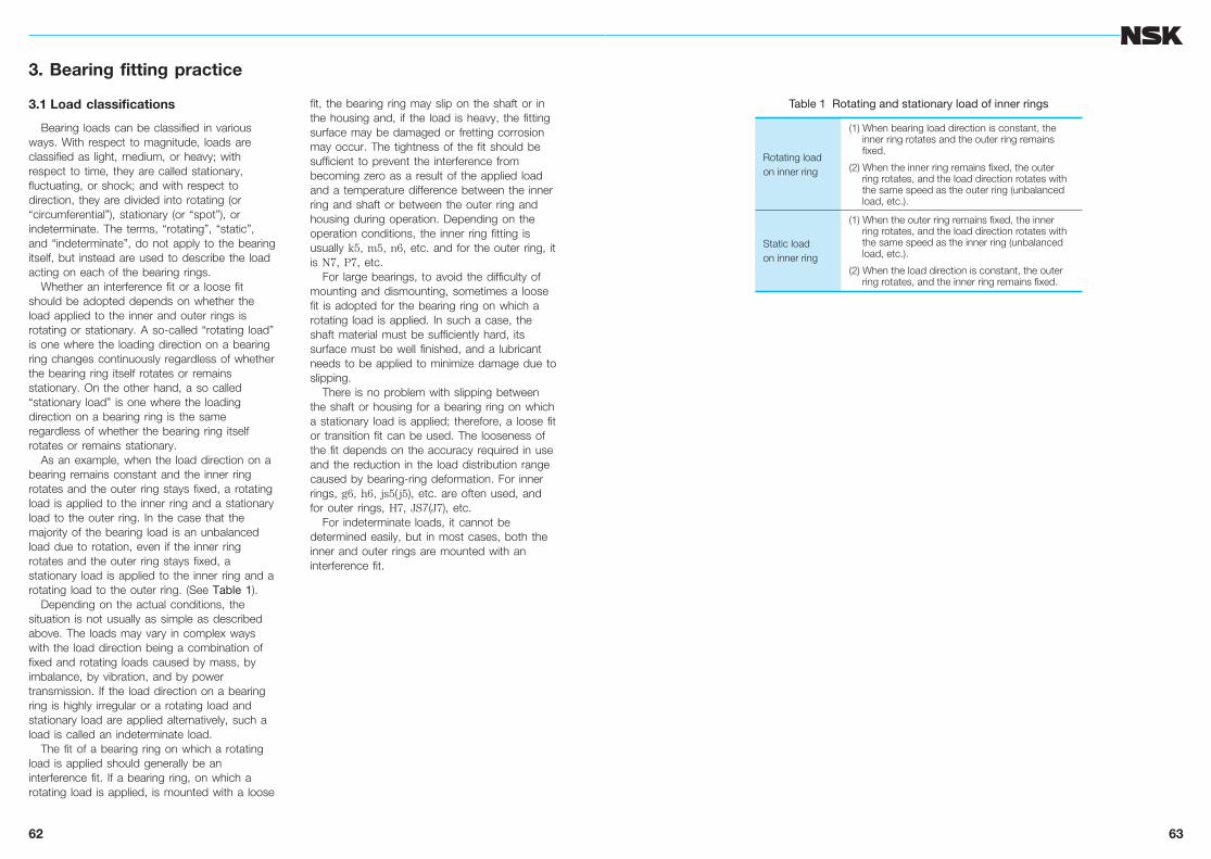
As an example, when the load direction on a bearing remains constant and the inner ring rotates and the outer ring stays fixed, a rotating load is applied to the inner ring and a stationary load to the outer ring. In the case that the majority of the bearing load is an unbalanced load due to rotation, even if the inner ring rotates and the outer ring stays fixed, a stationary load is applied to the inner ring and a rotating load to the outer ring. (See Table 1).
Depending on the actual conditions, the situation is not usually as simple as described above. The loads may vary in complex ways with the load direction being a combination of fixed and rotating loads caused by mass, by imbalance, by vibration, and by power transmission. If the load direction on a bearing ring is highly irregular or a rotating load and stationary load are applied alternatively, such a load is called an indeterminate load.
The fit of a bearing ring on which a rotating load is applied should generally be an interference fit. If a bearing ring, on which a rotating load is applied, is mounted with a loose
fit, the bearing ring may slip on the shaft or in the housing and, if the load is heavy, the fitting surface may be damaged or fretting corrosion may occur. The tightness of the fit should be sufficient to prevent the interference from becoming zero as a result of the applied load and a temperature difference between the inner ring and shaft or between the outer ring and housing during operation. Depending on the operation conditions, the inner ring fitting is usually k5, m5, n6, etc. and for the outer ring, it is N7, P7, etc.
For large bearings, to avoid the difficulty of mounting and dismounting, sometimes a loose fit is adopted for the bearing ring on which a rotating load is applied. In such a case, the shaft material must be sufficiently hard, its surface must be well finished, and a lubricant needs to be applied to minimize damage due to slipping.
There is no problem with slipping between the shaft or housing for a bearing ring on which a stationary load is applied; therefore, a loose fit or transition fit can be used. The looseness of the fit depends on the accuracy required in use and the reduction in the load distribution range caused by bearing-ring deformation. For inner rings, g6, h6, js5( j5), etc. are often used, and for outer rings, H7, JS7(J7), etc.
For indeterminate loads, it cannot be determined easily, but in most cases, both the inner and outer rings are mounted with an interference fit.
Table 1 Rotating and stationary load of inner rings
Rotating loadon inner ring
(1) When bearing load direction is constant, theinner ring rotates and the outer ring remainsfixed.
(2) When the inner ring remains fixed, the outerring rotates, and the load direction rotates withthe same speed as the outer ring (unbalancedload, etc.).
Static loadon inner ring
(1) When the outer ring remains fixed, the innerring rotates, and the load direction rotates withthe same speed as the inner ring (unbalancedload, etc.).
(2) When the load direction is constant, the outerring rotates, and the inner ring remains fixed.

64
Bearing fitting practice
65
3.2 Required effective interference due to load
The magnitude of the load is an important factor in determining the fit (interference tolerance) of a bearing.
When a load is applied to the inner ring, it is compressed radially and, at the same time, it expands circumferentially a little; thereby, the initial interference is reduced.
To obtain the interference reduction of the inner ring, Equation (1) is usually used.
DdF =0.08 Fr´10–3 (N)
............. (1)
=0.25 Fr´10–3 {kgf}
where DdF: Interference reduction of inner ring due to load (mm)
d: Inner ring bore diameter (mm) B: Inner ring width (mm) Fr: Radial load (N), {kgf}
Therefore, the effective interference Dd should be larger than the interference given by Equation (1).
The interference given by Equation (1) is sufficient for relatively low loads (less than about 0.2 C0r where C0r is the static load rating. For most general applications, this condition applies). However, under special conditions where the load is heavy (when Fr is close to C0r), the interference becomes insufficient.
For heavy radial loads exceeding 0.2 C0r, it is better to rely on Equation (2).
Dd ≧0.02 ´10–3 (N)
............. (2)
≧0.2 ´10–3 {kgf}
where Dd: Required effective interference due to load (mm)
B: Inner ring width (mm) Fr: Radial load (N), {kgf}
Creep experiments conducted by NSK with NU219 bearings showed a linear relation between radial load (load at creep occurrence limit) and required effective interference. It was confirmed that this line agrees well with the straight line of Equation (2).
For NU219, with the interference given by Equation (1) for loads heavier than 0.25 C0r, the interference becomes insufficient and creep occurs.
Generally speaking, the necessary interference for loads heavier than 0.25 C0r should be calculated using Equation (2). When doing this, sufficient care should be taken to prevent excessive circumferential stress.
Calculation exampleFor NU219, B=32 (mm) and assumeFr=98 100 N {10 000 kgf}C0r=183 000 N {18 600 kgf}
= =0.536>0.2
Therefore, the required effective interference is calculated using Equation (2).
Dd=0.02´ ´10–3=0.061 (mm)
This result agrees well with Fig. 1.
dB
dB
Fr
B
Fr
B
Fr
C0r
98 100183 000
98 10032
0
0 2 4 6 8 10
20
20
15
10
5
00
1
2
3
4
5
6
7
8
9
10
11
122
1.5
1
0.5
040 60 80 100 120×103
12×103
N
kgf
0.070
0.060
0.050
0.040
0.030
0.020
0.010
0
120
110
100
90
80
70
60
50
40
30
20
10
0
No creeping zone
Creeping zone
0.25
C0r
0.3C
0r 0.4C
0r
0.5C
0r
d = 0.02 ×
10−3
Fr
B
dF = 0.08 √ dB
Fr×10−3
D
D
Fig. 1 Load and required effective interference for fit

66
Bearing fitting practice
67
3.3 Interference deviation due to temperature rise (aluminum housing, plastic housing)
For reducing weight and cost or improving the performance of equipment, bearing housing materials such as aluminum, light alloys, or plastics (polyacetal resin, etc.) are often used.
When non-ferrous materials are used in housings, any temperature rise occurring during operation affects the interference or clearance of the outer ring due to the difference in the coefficients of linear expansion. This change is large for plastics which have high coefficients of linear expansion.
The deviation DDT of clearance or interference of a fitting surface of a bearing’s outer ring due to temperature rise is expressed by the following equation:
DDT=(a1·DT1–a2·DT2)D (mm) ...................... (1)
where DDT: Change of clearance or interference at fitting surface due to temperature rise
a1: Coefficient of linear expansion of housing (1/°C)
DT1: Housing temperature rise near fitting surface (°C)
a2: Coefficient of linear expansion of bearing outer ring
Bearing steel .... a2=12.5´10–6 (1/°C)
DT2: Outer ring temperature rise near fitting surface (°C)
D: Bearing outside diameter (mm)In general, the housing temperature rise and
that of the outer ring are somewhat different, but if we assume they are approximately equal near the fitting surfaces, (DT1≒DT2=DT ), Equation (1) becomes,
DDT=(a1–a2) DT ·D (mm) ............................. (2)
where DT: Temperature rise of outer ring and housing near fitting surfaces (°C)
In the case of an aluminum housing (a1=23.7´10–6), Equation (2) can be shown graphically as in Fig. 1.
Among the various plastics, polyacetal resin is one that is often used for bearing housings. The coefficients of linear expansion of plastics may vary or show directional characteristics. In the case of polyacetal resin, for molded products, it is approximately 9´10–5. Equation (2) can be shown as in Fig. 2.
Fig. 1 Aluminum housing
Fig. 2 Polyacetal resin housing
68
Bearing fitting practice
69
3.4 Fit calculation
It is easier to mount a bearings with a loose fit than with an interference fit. However, if there is clearance between the fitting surfaces or too little interference, depending on the loading condition, creep may occur and damage the fitting surfaces; therefore, a sufficient interference must be chosen to prevent such damage.
The most common loading condition is to have a fixed load and fixed direction with the inner ring (i.e. shaft) rotating and the outer ring stationary. This condition is referred to as a rotating load on the inner ring or a stationary load on the outer ring. In other words, a circumferential load is applied to the inner ring and a spot load on the outer ring.
In the case of automobile wheels, a circumferential load is applied to the outer ring (rotating load on outer ring) and a spot load on the inner ring. In any case, for a spot load, the interference can be almost negligible, but it must be tight for the bearing ring to which a circumferential load is applied.
For indeterminate loads caused by unbalanced weight, vibration, etc., the magnitude of the interference should be almost the same as for circumferential loads. The interference appropriate for the tolerances of the shaft and housing given in the bearing manufacturer’s catalog is sufficient for most cases.
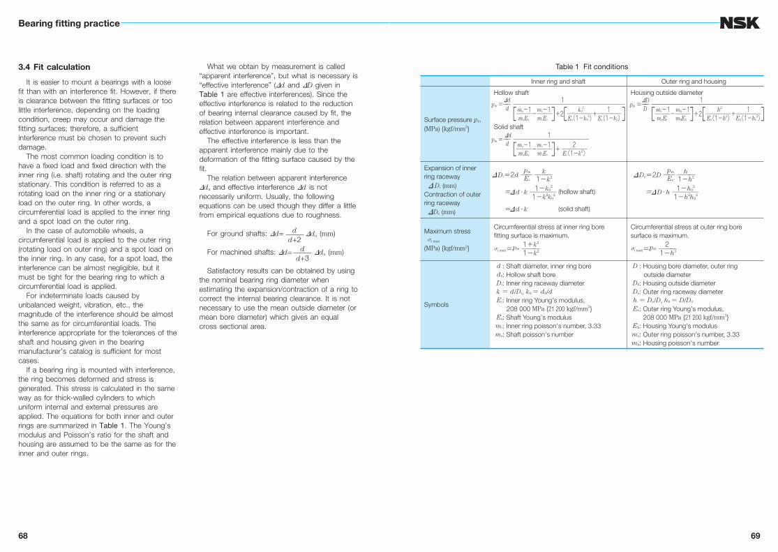
If a bearing ring is mounted with interference, the ring becomes deformed and stress is generated. This stress is calculated in the same way as for thick-walled cylinders to which uniform internal and external pressures are applied. The equations for both inner and outer rings are summarized in Table 1. The Young’s modulus and Poisson’s ratio for the shaft and housing are assumed to be the same as for the inner and outer rings.
What we obtain by measurement is called “apparent interference”, but what is necessary is “effective interference” (Dd and DD given in Table 1 are effective interferences). Since the effective interference is related to the reduction of bearing internal clearance caused by fit, the relation between apparent interference and effective interference is important.
The effective interference is less than the apparent interference mainly due to the deformation of the fitting surface caused by the fit.
The relation between apparent interference Dda and effective interference Dd is not necessarily uniform. Usually, the following equations can be used though they differ a little from empirical equations due to roughness.
For ground shafts: Dd= Dda (mm)
For machined shafts: Dd= Dda (mm)
Satisfactory results can be obtained by using the nominal bearing ring diameter when estimating the expansion/contraction of a ring to correct the internal bearing clearance. It is not necessary to use the mean outside diameter (or mean bore diameter) which gives an equal cross sectional area.
dd+2
dd+3
Table 1 Fit conditions
Inner ring and shaft Outer ring and housing
Surface pressure pm
(MPa) {kgf/mm2}
Hollow shaft
Solid shaft
Housing outside diameter
Expansion of innerring raceway
D Di (mm)Contraction of outerring racewayDDe (mm)
(hollow shaft)
(solid shaft)
Maximum stress σt max
(MPa) {kgf/mm2}
Circumferential stress at inner ring borefitting surface is maximum.
Circumferential stress at outer ring boresurface is maximum.
Symbols
d: Shaft diameter, inner ring bored0: Hollow shaft boreDi: Inner ring raceway diameter
k= d/Di, k0 = d0/dEi: Inner ring Young
,s modulus,
208 000 MPa {21 200 kgf/mm2}Es: Shaft Young
,s modulus
mi: Inner ring poisson,s number, 3.33
ms: Shaft poisson,s number
D: Housing bore diameter, outer ring outside diameter
D0: Housing outside diameterDe: Outer ring raceway diameter
h= De/D, h0 = D/D0
Ee: Outer ring Young,s modulus,
208 000 MPa {21 200 kgf/mm2}Eh: Housing Young
,s modulus
me: Outer ring poisson,s number, 3.33
mh: Housing poisson,s number
DDe=2D ── ───
=DD・h ────
pm
Ee
h1−h2
1−h02
1−h2h02
DDi=2d ── ───
=Dd・k ────
=Dd・k
pm
Ei
k1−k2
1−k02
1−k2k02
2σt max=pm ─── 1−h2
1+k2
σt max=pm ─── 1−k2
Dd 1pm =── ────────────────────── d ms−1 mi−1 k0
2 1───−─── +2 ─────+───── msEs miEi Es(1−k02) Ei(1−k2)[ ][ ]
DD 1pm =── ────────────────────── D me−1 mh−1 h2 1───−─── +2 ─────+───── meEe mhEh Ee(1−h2) Eh(1−h0
2)[ ][ ] Dd 1pm =── ─────────────── d ms−1 mi−1 2───−─── + ───── msEs miEi Ei(1−k2)[ ]
70
Bearing fitting practice
71
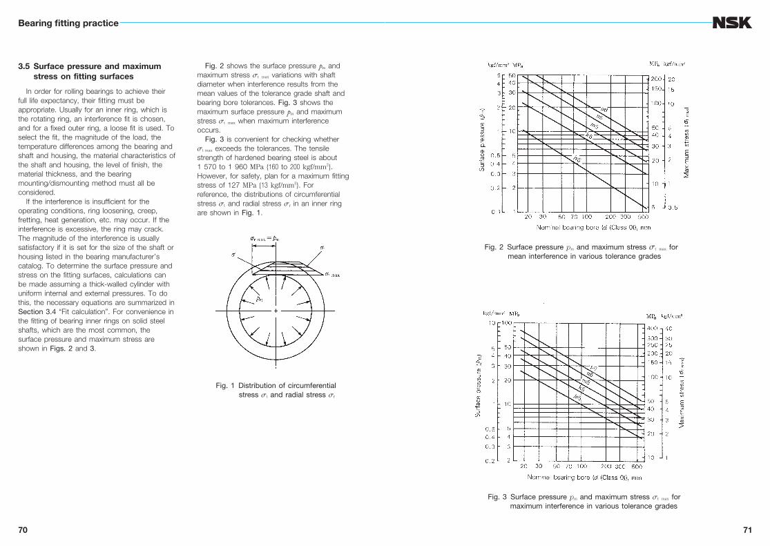
3.5 Surface pressure and maximum stress on fitting surfaces
In order for rolling bearings to achieve their full life expectancy, their fitting must be appropriate. Usually for an inner ring, which is the rotating ring, an interference fit is chosen, and for a fixed outer ring, a loose fit is used. To select the fit, the magnitude of the load, the temperature differences among the bearing and shaft and housing, the material characteristics of the shaft and housing, the level of finish, the material thickness, and the bearing mounting/dismounting method must all be considered.
If the interference is insufficient for the operating conditions, ring loosening, creep, fretting, heat generation, etc. may occur. If the interference is excessive, the ring may crack. The magnitude of the interference is usually satisfactory if it is set for the size of the shaft or housing listed in the bearing manufacturer’s catalog. To determine the surface pressure and stress on the fitting surfaces, calculations can be made assuming a thick-walled cylinder with uniform internal and external pressures. To do this, the necessary equations are summarized in Section 3.4 “Fit calculation”. For convenience in the fitting of bearing inner rings on solid steel shafts, which are the most common, the surface pressure and maximum stress are shown in Figs. 2 and 3.
Fig. 2 shows the surface pressure pm and maximum stress σt max variations with shaft diameter when interference results from the mean values of the tolerance grade shaft and bearing bore tolerances. Fig. 3 shows the maximum surface pressure pm and maximum stress σt max when maximum interference occurs.
Fig. 3 is convenient for checking whether σt max exceeds the tolerances. The tensile strength of hardened bearing steel is about 1 570 to 1 960 MPa {160 to 200 kgf/mm2}. However, for safety, plan for a maximum fitting stress of 127 MPa {13 kgf/mm2}. For reference, the distributions of circumferential stress σt and radial stress σr in an inner ring are shown in Fig. 1.
Fig. 1 Distribution of circumferential stress σt and radial stress σr
Fig. 2 Surface pressure pm and maximum stress σt max for mean interference in various tolerance grades
Fig. 3 Surface pressure pm and maximum stress σt max for maximum interference in various tolerance grades
72
Bearing fitting practice
73
3.6 Mounting and withdrawal loads
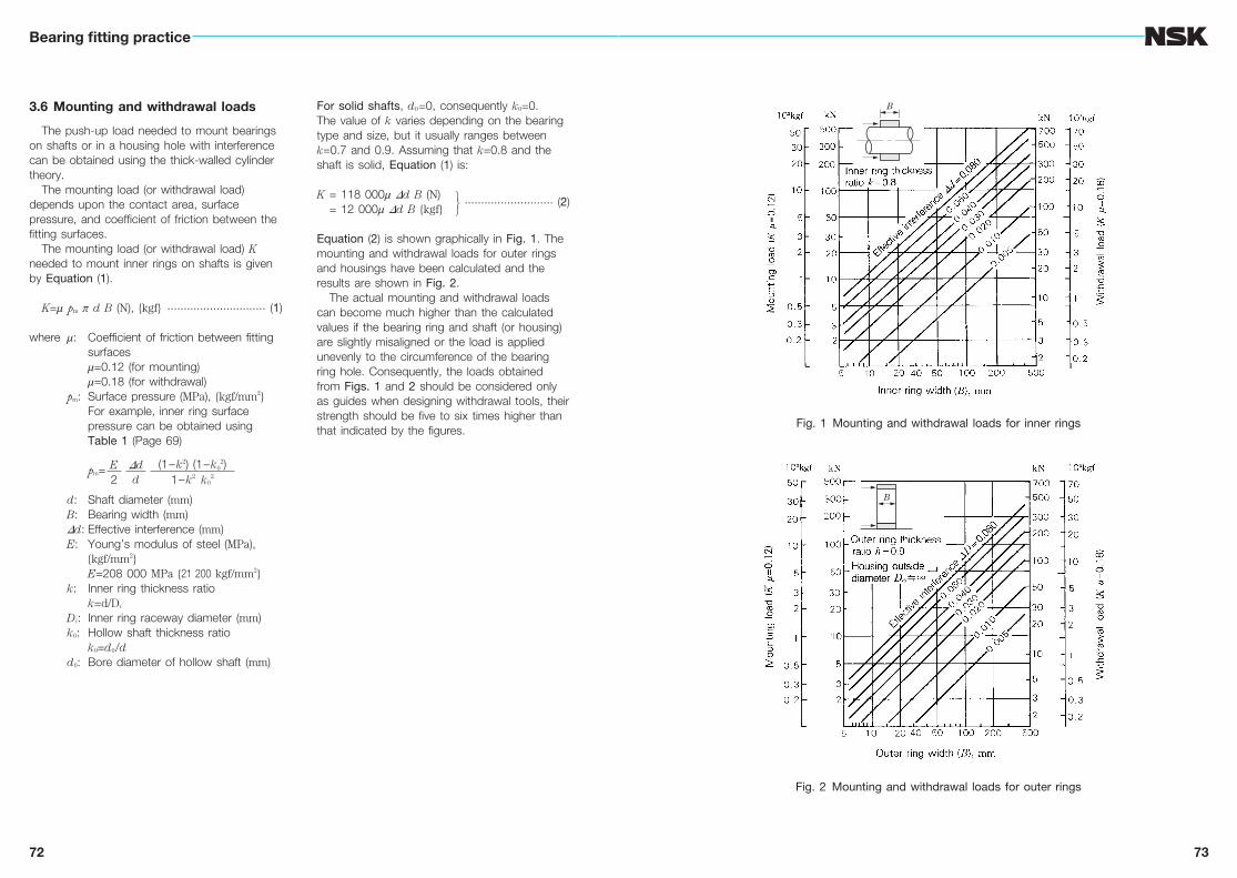
The push-up load needed to mount bearings on shafts or in a housing hole with interference can be obtained using the thick-walled cylinder theory.
The mounting load (or withdrawal load) depends upon the contact area, surface pressure, and coefficient of friction between the fitting surfaces.
The mounting load (or withdrawal load) K needed to mount inner rings on shafts is given by Equation (1).
K=m pm p dB (N), {kgf} .............................. (1)
where m: Coefficient of friction between fitting surfaces
m=0.12 (for mounting) m=0.18 (for withdrawal) pm: Surface pressure (MPa), {kgf/mm2} For example, inner ring surface
pressure can be obtained using Table 1 (Page 69)
pm=
d: Shaft diameter (mm) B: Bearing width (mm) Dd: Effective interference (mm) E: Young’s modulus of steel (MPa),
{kgf/mm2} E=208 000 MPa {21 200 kgf/mm2} k: Inner ring thickness ratio k=d/Di
Di: Inner ring raceway diameter (mm) k0: Hollow shaft thickness ratio k0=d0/d d0: Bore diameter of hollow shaft (mm)
For solid shafts, d0=0, consequently k0=0. The value of k varies depending on the bearing type and size, but it usually ranges between k=0.7 and 0.9. Assuming that k=0.8 and the shaft is solid, Equation (1) is:
K= 118 000m Dd B (N) ........................... (2)
= 12 000m Dd B {kgf}
Equation (2) is shown graphically in Fig. 1. The mounting and withdrawal loads for outer rings and housings have been calculated and the results are shown in Fig. 2.
The actual mounting and withdrawal loads can become much higher than the calculated values if the bearing ring and shaft (or housing) are slightly misaligned or the load is applied unevenly to the circumference of the bearing ring hole. Consequently, the loads obtained from Figs. 1 and 2 should be considered only as guides when designing withdrawal tools, their strength should be five to six times higher than that indicated by the figures.
E2
Ddd
(1–k2) (1–k02)
1–k2 k02
B
B
Fig. 1 Mounting and withdrawal loads for inner rings
Fig. 2 Mounting and withdrawal loads for outer rings
B
B
74
Bearing fitting practice
75
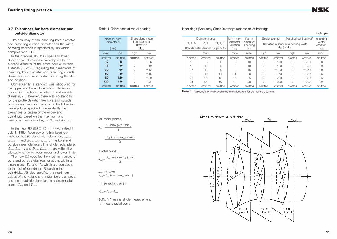
3.7 Tolerances for bore diameter and outside diameter
The accuracy of the inner-ring bore diameter and outer-ring outside diameter and the width of rolling bearings is specified by JIS which complies with ISO.
In the previous JIS, the upper and lower dimensional tolerances were adopted to the average diameter of the entire bore or outside surfaces (dm or Dm) regarding the dimensions of inner ring bore diameter and outer ring outside diameter which are important for fitting the shaft and housing.
Consequently, a standard was introduced for the upper and lower dimensional tolerances concerning the bore diameter, d, and outside diameter, D. However, there was no standard for the profile deviation like bore and outside out-of-roundness and cylindricity. Each bearing manufacturer specified independently the tolerances or criteria of the ellipse and cylindricity based on the maximum and minimum tolerances of dm or Dm and d or D.
In the new JIS (JIS B 1514 : 1986, revised in July 1, 1986, Accuracy of rolling bearings) matched to ISO standards, tolerances, DdmpI, DdmpII, ... and DDmpI, DDmpII, ..., of the bore and outside mean diameters in a single radial plane, dmpI, dmpII, ... and DmpI, DmpII, ..., are within the allowable range between upper and lower limits.
The new JIS specifies the maximum values of bore and outside diameter variations within a single plane, Vdp and VDp which are equivalent to the out-of-roundness. Regarding the cylindricity, JIS also specifies the maximum values of the variations of mean bore diameters and mean outside diameters in a single radial plane, Vdmp and VDmp.
[All radial planes]
dm =
=
[Radial plane I]
dmpI=
DDmpI=dmpI–dVdpI=dspI (max.)–dspI (min.)
[Three radial planes]
Vdmp=dmpI –dmpII
Suffix “s” means single measurement, “p” means radial plane.
ds (max.)+ds (min.)2
dspI (max.)+dspII (min.)2
dspI (max.)+dspI (min.)2
Table 1 Tolerances of radial bearing
Nominal borediameter d
(mm)
Single plane meanbore diameter
deviationD dmp
over incl high low
omitted 10 18 30 50 80120
omitted
omitted 18 30 50 80120180
omitted
omitted000000
omitted
omitted− 8−10−12−15−20−25
omitted
Note ( 1 ) Applicable to individual rings manufactured for combined bearings.
inner rings (Accuracy Class 0) except tapered roller bearings
Diameter series Mean borediametervariation
Vdmp
Radialrunout ofinner ring
Kia
Single bearing Matched set bearing(1) Inner ringwidth
variationVBs
7, 8, 9 0, 1 2, 3, 4 Deviation of inner or outer ring widthD Bs ( orD Cs )Bore diameter variation in a plane Vdp
max. max. max. high low high low max.
omitted101315192531
omitted
omitted 81012192531
omitted
omitted 6 8 9111519
omitted
omitted 6 8 9111519
omitted
omitted101315202530
omitted
omitted000000
omitted
omitted−120−120−120−150−200−250
omitted
omitted000000
omitted
omitted−250−250−250−380−380−500
omitted
omitted202020252530
omitted
Units: mm
76
Bearing fitting practice
77
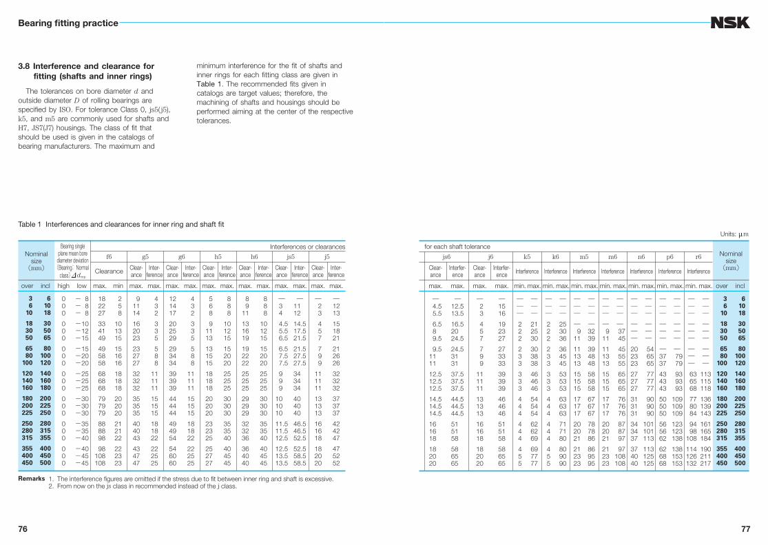
3.8 Interference and clearance for fitting (shafts and inner rings)
The tolerances on bore diameter d and outside diameter D of rolling bearings are specified by ISO. For tolerance Class 0, js5( j5), k5, and m5 are commonly used for shafts and H7, JS7(J7) housings. The class of fit that should be used is given in the catalogs of bearing manufacturers. The maximum and
minimum interference for the fit of shafts and inner rings for each fitting class are given in Table 1. The recommended fits given in catalogs are target values; therefore, the machining of shafts and housings should be performed aiming at the center of the respective tolerances.
Remarks 1. The interference figures are omitted if the stress due to fit between inner ring and shaft is excessive. 2. From now on the js class in recommended instead of the j class.
Table 1 Interferences and clearances for inner ring and shaft fit
Nominalsize
(mm)
Bearing singleplane mean bore
diameter deviation(Bearing: Normal
class) Ddmp
Interferences or clearances
f6 g5 g6 h5 h6 js5 j5
Clearance Clear-ance
Inter-ference
Clear-ance
Inter-ference
Clear-ance
Inter-ference
Clear-ance
Inter-ference
Clear-ance
Inter-ference
Clear-ance
Inter-ference
over incl high low max. min max. max. max. max. max. max. max. max. max. max. max. max.
3 6 10
18 30 50
65 80100
120140160
180200225
250280315
355400450
6 10 18
30 50 65
80100120
140160180
200225250
280315355
400450500
000
000
000
000
000
000
000
− 8− 8− 8
−10−12−15
−15−20−20
−25−25−25
−30−30−30
−35−35−40
−40−45−45
18 22 27
33 41 49
49 58 58
68 68 68
79 79 79
88 88 98
98108108
2 5 8
101315
151616
181818
202020
212122
222323
91114
162023
232727
323232
353535
404043
434747
4 3 2
3 3 5
5 8 8
111111
151515
181822
222525
121417
202529
293434
393939
444444
494954
546060
4 3 2
3 3 5
5 8 8
111111
151515
181822
222525
5 6 8
91113
131515
181818
202020
232325
252727
8 8 8
101215
152020
252525
303030
353540
404545
8 911
131619
192222
252525
292929
323236
364040
8 8 8
101215
152020
252525
303030
353540
404545
―34
4.55.56.5
6.57.57.5
999
101010
11.511.512.5
12.513.513.5
―1112
14.517.521.5
21.527.527.5
343434
404040
46.546.552.5
52.558.558.5
― 2 3
4 5 7
7 9 9
111111
131313
161618
182020
―1213
151821
212626
323232
373737
424247
475252
Units: mm
for each shaft toleranceNominal
size(mm)
js6 j6 k5 k6 m5 m6 n6 p6 r6
Clear-ance
Interfer-ence
Clear-ance
Interfer-ence Interference Interference Interference Interference Interference Interference Interference
max. max. max. max. min. max. min. max. min. max. min. max. min. max. min. max. min. max. over incl
―4.55.5
6.589.5
9.51111
12.512.512.5
14.514.514.5
161618
182020
―12.513.5
16.52024.5
24.53131
37.537.537.5
44.544.544.5
515158
586565
― 2 3
4 5 7
7 9 9
111111
131313
161618
182020
―1516
192327
273333
393939
464646
515158
586565
―――222
233
333
444
444
455
―――212530
303838
464646
545454
626269
697777
―――222
233
333
444
444
455
―――253036
364545
535353
636363
717180
809090
―――― 911
111313
151515
171717
202021
212323
――――3239
394848
585858
676767
787886
869595
―――― 911
111313
151515
171717
202021
212323
――――
37 45
45 55 55
65 65 65
76 76 76
87 87 97
97108108
――――――202323
272727
313131
343437
374040
――――――
54 65 65
77 77 77
90 90 90
101101113
113125125
―――――――3737
434343
505050
565662
626868
―――――――
79 79
93 93 93
109109109
123123138
138153153
―――――――――
63 65 68
77 80 84
94 98108
114126132
―――――――――
113115118
136139143
161165184
190211217
3 6 10
18 30 50
65 80100
120140160
180200225
250280315
355400450
6 10 18
30 50 65
80100120
140160180
200225250
280315355
400450500
78
Bearing fitting practice
79
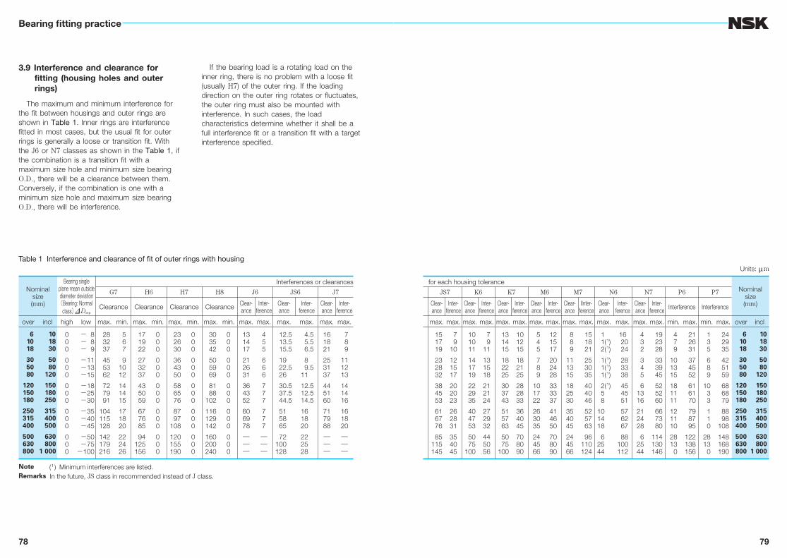
3.9 Interference and clearance for fitting (housing holes and outer rings)
The maximum and minimum interference for the fit between housings and outer rings are shown in Table 1. Inner rings are interference fitted in most cases, but the usual fit for outer rings is generally a loose or transition fit. With the J6 or N7 classes as shown in the Table 1, if the combination is a transition fit with a maximum size hole and minimum size bearing O.D., there will be a clearance between them. Conversely, if the combination is one with a minimum size hole and maximum size bearing O.D., there will be interference.
If the bearing load is a rotating load on the inner ring, there is no problem with a loose fit (usually H7) of the outer ring. If the loading direction on the outer ring rotates or fluctuates, the outer ring must also be mounted with interference. In such cases, the load characteristics determine whether it shall be a full interference fit or a transition fit with a target interference specified.
Note ( 1 ) Minimum interferences are listed.Remarks In the future, JS class in recommended instead of J class.
Table 1 Interference and clearance of fit of outer rings with housing
Nominalsize(mm)
Bearing single plane mean outside diameter deviation (Bearing: Normal
class) DDmp
Interferences or clearances
G7 H6 H7 H8 J6 JS6 J7
Clearance Clearance Clearance Clearance Clear-ance
Inter-ference
Clear-ance
Inter-ference
Clear-ance
Inter-ference
over incl high low max. min. max. min. max. min. max. min. max. max. max. max. max. max.
6 10 18
30 50 80
120150180
250315400
500630800
10 18 30
50 80 120
150 180 250
315 400 500
630 8001 000
000
000
000
000
000
− 8 − 8 − 9
−11 −13 −15
−18 −25 −30
−35 −40 −45
−50 −75−100
28 32 37
45 53 62
72 79 91
104115128
142179216
5 6 7
91012
141415
171820
222426
17 19 22
27 32 37
43 50 59
67 76 85
94125156
000
000
000
000
000
23 26 30
36 43 50
58 65 76
87 97108
120155190
000
000
000
000
000
30 35 42
50 59 69
81 88102
116129142
160200240
000
000
000
000
000
131417
212631
364352
606978
―――
455
666
777
777
―――
12.513.515.5
1922.526
30.537.544.5
515865
72100128
4.55.56.5
89.5
11
12.512.514.5
161820
222528
161821
253137
445160
717988
―――
7 8 9
111213
141416
161820
―――
Units: mm
for each housing toleranceNominal
size(mm)
JS7 K6 K7 M6 M7 N6 N7 P6 P7
Clear-ance
Inter-ference
Clear-ance
Inter-ference
Clear-ance
Inter-ference
Clear-ance
Inter-ference
Clear-ance
IInter-ference
Clear-ance
Inter-ference
Clear-ance
Inter-ference Interference Interference
max. max. max. max. max. max. max. max. max. max. max. max. max. max. min. max. min. max. over incl
15 17 19
23 28 32
38 45 53
61 67 76
85115145
7 910
121517
202023
262831
354045
10 10 11
14 17 19
22 29 35
40 47 53
50 75100
7 911
131518
212124
272932
445056
13 14 15
18 22 25
30 37 43
51 57 63
50 75100
101215
182125
282833
364045
708090
5 4 5
7 8 9
101722
263035
244566
121517
202428
333337
414650
708090
8 8 9
111315
182530
354045
244566
15 18 21
25 30 35
40 40 46
52 57 63
96110124
11(1)2(1)
1(1)1(1)1(1)
2(1)58
101418
62544
16 20 24
28 33 38
45 45 51
57 62 67
88100112
4 3 2
3 4 5
61316
212428
62544
19 23 28
33 39 45
52 52 60
66 73 80
114130146
4 7 9
101315
181111
121110
2813 0
21 26 31
37 45 52
61 61 70
79 87 95
122138156
1 3 5
6 8 9
10 3 3
1 1 0
2813 0
24 29 35
42 51 59
68 68 79
88 98108
148168190
6 10 18
30 50 80
120150180
250315400
500630800
10 18 30
50 80 120
150 180 250
315 400 500
630 8001 000

80
Bearing fitting practice
81
3.10 Interference dispersion (shafts and inner rings)
The residual clearance in bearings is calculated by subtracting from the initial radial clearance the expansion or contraction of the bearing rings caused by their fitting.
In this residual clearance calculation, usually the pertinent bearing dimensions (shaft diameter, bore diameter of inner ring, bore diameter of housing, outside diameter of outer ring) are assumed to have a normal (Guassian) distribution within their respective tolerance specifications.
If the shaft diameter and inner-ring bore diameter both have normal (Gaussian) distributions and their reject ratios are the same, then the range of distribution of interference R (dispersion) that has the same reject ratio as the shaft and inner-ring bore is given by the following equation:
R= Rs2+Ri
2 ................................................. (1)
where Rs: Shaft diameter tolerance (range of specification)
Ri: Inner-ring bore diameter tolerance (range of specification)
The mean interference and its dispersion R based on the tolerances on inner-ring bore diameters d of radial bearings of Normal Class and shafts of Classes 5 and 6 are shown in Table 1.
√————
Note ( 1 ) Negative mean value of the interference indicates
Table 1 Mean value and dispersion of
Nominalsize(mm)
Bearing singleplane mean bore
diameter deviation(Bearing: Normal
class) Ddmp
Fit with Class
Mean value of
over incl high low h5 js5 j5
― 3 6
10 18 30
50 65 80
100120140
160180200
225250280
315355400
3 6 10
18 30 50
65 80100
120140160
180200225
250280315
355400450
000
000
000
000
000
000
000
− 8− 8− 8
− 8−10−12
−15−15−20
−20−25−25
−25−30−30
−30−35−35
−40−40−45
21.51
00.50.5
112.5
2.53.53.5
3.555
566
7.57.59
444
456
7.57.5
10
1012.512.5
12.51515
1517.517.5
202022.5
44.55
55.56.5
778.5
8.510.510.5
10.51212
121313
14.514.516
clearance.
interference for fitting of inner rings with shaftsUnits: mm
5 shaft Fit with Class 6 shaft
interference Dispersion ofinterference
R= Rs2+Ri
2
Mean value of interference (1) Dispersion ofinterference
R= Rs2+Ri
2k5 m5 h6 js6 j6 k6 m6 n6 p6 r6
67.58
911.513.5
161620.5
20.524.524.5
24.52929
293333
36.536.541
810.513
1517.520.5
252530.5
30.536.536.5
36.54242
424949
53.553.559
± 4.5± 4.5± 5
± 5.5± 6.5± 8
±10±10±12.5
±12.5±15.5±15.5
±15.5±18±18
±18±21±21
±23.5±23.5±26
10
−0.5
−1.5−1.5−2
−2−2−1
−100
00.50.5
0.51.51.5
222.5
444
456
7.57.5
10
1012.512.5
12.51515
1517.517.5
202022.5
566.5
6.57.59
101012
121414
1416.516.5
16.517.517.5
202022.5
799.5
10.513.516
191924
242828
2833.533.5
33.537.537.5
424247.5
91214.5
16.519.523
282834
344040
4046.546.5
46.553.553.5
595965.5
111618.5
21.526.531
373744
445252
5260.560.5
60.567.567.5
757582.5
132023.5
27.533.540
494958
586868
6879.579.5
79.589.589.5
100100110.5
172327.5
32.539.548
586072
758890
93106.5109.5
113.5127.5131.5
146152168.5
± 5± 5.5± 6
± 7± 8±10
±12±12±15
±15±17.5±17.5
±17.5±21±21
±21±23.5±23.5
±27±27±30
82
Bearing fitting practice
83
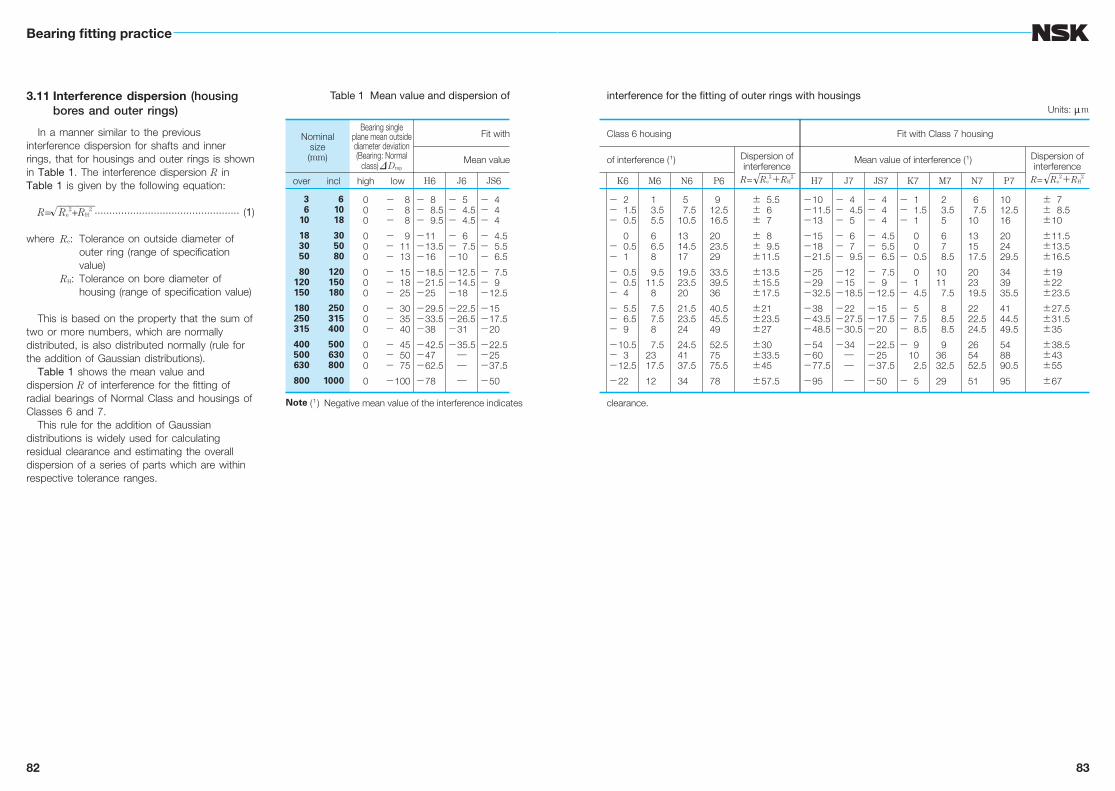
3.11 Interference dispersion (housing bores and outer rings)
In a manner similar to the previous interference dispersion for shafts and inner rings, that for housings and outer rings is shown in Table 1. The interference dispersion R in Table 1 is given by the following equation:
R= Re2+RH
2 ................................................. (1)
where Re: Tolerance on outside diameter of outer ring (range of specification value)
RH: Tolerance on bore diameter of housing (range of specification value)
This is based on the property that the sum of two or more numbers, which are normally distributed, is also distributed normally (rule for the addition of Gaussian distributions).
Table 1 shows the mean value and dispersion R of interference for the fitting of radial bearings of Normal Class and housings of Classes 6 and 7.
This rule for the addition of Gaussian distributions is widely used for calculating residual clearance and estimating the overall dispersion of a series of parts which are within respective tolerance ranges.
√————
Note ( 1 ) Negative mean value of the interference indicates
Table 1 Mean value and dispersion of
Nominalsize(mm)
Bearing singleplane mean outsidediameter deviation(Bearing: Normal
class) DDmp
Fit with
Mean value
over incl high low H6 J6 JS6
3 6 10
18 30 50
80120150
180250315
400500630
800
6 10 18
30 50 80
120 150 180
250 315 400
500 630 800
1000
000
000
000
000
000
0
− 8− 8− 8
− 9− 11− 13
− 15− 18− 25
− 30− 35− 40
− 45− 50− 75
−100
− 8− 8.5− 9.5
−11−13.5−16
−18.5−21.5−25
−29.5−33.5−38
−42.5−47−62.5
−78
− 5− 4.5− 4.5
− 6− 7.5−10
−12.5−14.5−18
−22.5−26.5−31
−35.5―――
− 4− 4− 4
− 4.5− 5.5− 6.5
− 7.5− 9−12.5
−15−17.5−20
−22.5−25−37.5
−50
clearance.
interference for the fitting of outer rings with housingsUnits: mm
Class 6 housing Fit with Class 7 housing
of interference (1) Dispersion ofinterference
R= Re2+RH
2
Mean value of interference (1) Dispersion ofinterference
R= Re2+RH
2K6 M6 N6 P6 H7 J7 JS7 K7 M7 N7 P7
− 2− 1.5− 0.5
0− 0.5− 1
− 0.5− 0.5− 4
− 5.5− 6.5− 9
−10.5− 3−12.5
−22
13.55.5
66.58
9.511.5
8
7.57.58
7.52317.5
12
57.5
10.5
1314.517
19.523.520
21.523.524
24.54137.5
34
912.516.5
2023.529
33.539.536
40.545.549
52.57575.5
78
± 5.5± 6± 7
± 8± 9.5±11.5
±13.5±15.5±17.5
±21±23.5±27
±30±33.5±45
±57.5
−10−11.5−13
−15−18−21.5
−25−29−32.5
−38−43.5−48.5
−54−60−77.5
−95
− 4− 4.5− 5
− 6− 7− 9.5
−12−15−18.5
−22−27.5−30.5
−34―――
− 4− 4− 4
− 4.5− 5.5− 6.5
− 7.5− 9−12.5
−15−17.5−20
−22.5−25−37.5
−50
− 1− 1.5− 1
00
− 0.5
0− 1− 4.5
− 5− 7.5− 8.5
− 910
2.5
− 5
23.55
678.5
1011
7.5
88.58.5
93632.5
29
67.5
10
131517.5
202319.5
2222.524.5
265452.5
51
1012.516
202429.5
343935.5
4144.549.5
548890.5
95
± 7± 8.5±10
±11.5±13.5±16.5
±19±22±23.5
±27.5±31.5±35
±38.5±43±55
±67
84
Bearing fitting practice
85
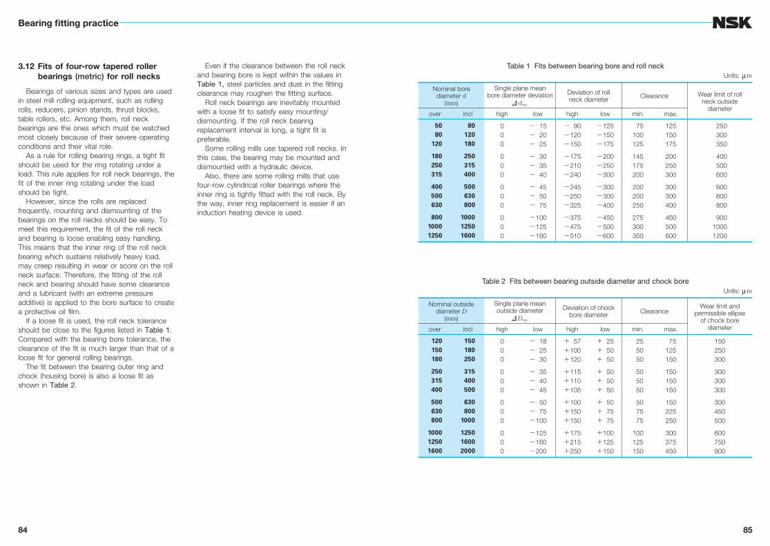
3.12 Fits of four-row tapered roller bearings (metric) for roll necks
Bearings of various sizes and types are used in steel mill rolling equipment, such as rolling rolls, reducers, pinion stands, thrust blocks, table rollers, etc. Among them, roll neck bearings are the ones which must be watched most closely because of their severe operating conditions and their vital role.
As a rule for rolling bearing rings, a tight fit should be used for the ring rotating under a load. This rule applies for roll neck bearings, the fit of the inner ring rotating under the load should be tight.
However, since the rolls are replaced frequently, mounting and dismounting of the bearings on the roll necks should be easy. To meet this requirement, the fit of the roll neck and bearing is loose enabling easy handling. This means that the inner ring of the roll neck bearing which sustains relatively heavy load, may creep resulting in wear or score on the roll neck surface. Therefore, the fitting of the roll neck and bearing should have some clearance and a lubricant (with an extreme pressure additive) is applied to the bore surface to create a protective oil film.
If a loose fit is used, the roll neck tolerance should be close to the figures listed in Table 1. Compared with the bearing bore tolerance, the clearance of the fit is much larger than that of a loose fit for general rolling bearings.
The fit between the bearing outer ring and chock (housing bore) is also a loose fit as shown in Table 2.
Even if the clearance between the roll neck and bearing bore is kept within the values in Table 1, steel particles and dust in the fitting clearance may roughen the fitting surface.
Roll neck bearings are inevitably mounted with a loose fit to satisfy easy mounting/dismounting. If the roll neck bearing replacement interval is long, a tight fit is preferable.
Some rolling mills use tapered roll necks. In this case, the bearing may be mounted and dismounted with a hydraulic device.
Also, there are some rolling mills that use four-row cylindrical roller bearings where the inner ring is tightly fitted with the roll neck. By the way, inner ring replacement is easier if an induction heating device is used.
Table 1 Fits between bearing bore and roll neckUnits: mm
Nominal borediameter d
(mm)
Single plane meanbore diameter deviation
D dmp
Deviation of roll neck diameter Clearance Wear limit of roll
neck outside diameter
over incl high low high low min. max.
50 80 120
180 250 315
400 500 630
80010001250
80 120 180
250 315 400
500 630 800
100012501600
000
000
000
000
− 15− 20− 25
− 30− 35− 40
− 45− 50− 75
−100−125−160
− 90−120−150
−175−210−240
−245−250−325
−375−475−510
−125−150−175
−200−250−300
−300−300−400
−450−500−600
75100125
145175200
200200250
275300350
125150175
200250300
300300400
450500600
250 300 350
400 500 600
600 600 800
90010001200
Table 2 Fits between bearing outside diameter and chock boreUnits: mm
Nominal outsidediameter D
(mm)
Single plane meanoutside diameter
D Dmp
Deviation of chockbore diameter Clearance
Wear limit andpermissible ellipse
of chock borediameterover incl high low high low min. max.
120 150 180
250 315 400
500 630 800
100012501600
150 180 250
315 400 500
630 8001000
125016002000
000
000
000
000
− 18− 25− 30
− 35− 40− 45
− 50− 75−100
−125−160−200
+ 57+100+120
+115+110+105
+100+150+150
+175+215+250
+ 25+ 50+ 50
+ 50+ 50+ 50
+ 50+ 75+ 75
+100+125+150
25 50 50
50 50 50
50 75 75
100125150
75125150
150150150
150225250
300375450
150250300
300300300
300450500
600750900