3 11 0967 - nasa · pdf file3 11 0967 _. nasa-cr-159010 nasa contractor report 159010...
TRANSCRIPT

3 11 0967 _.NASA-CR- 159010
NASA Contractor Report 159010 19810018578
747 PRIMARY FLIGHT CONTROL SYSTEMSRELIABILITY AND MAINTENANCE
• _ ENERGY EFFICIENTTRANSPORT PROGRAM
BOEINGCOMMERCIALAIRPLANECOMPANY,
• . P.O, BOX 3707, SEATTLE,WA98124
CONTRACT NASI-14742, TASK 4.6APRI L 1979
B__possible commercial value, this data developed under U.S. Govern_act NASI-
• 14142 iT___0__ithin the U.S. in advance of general pu__ata may be_y'_ r¢c_-_!ct_a will not bepublished
nor willitbe releasedtoforeignpartieswithotitPi__h_Boeing Company. Releaseof
.... partie s - "-_-'-_'_:_ _._ ._-_£_ni_,__these:_: ....this data to other domestic b g _dq_J'_n_- slJall only f),e limitations.The limitations contained irt_ffd_wl_hl be considered void after April 1981_ Thi_'_!l-be
"_ of this'r_-''- - data in whole or in part. ........ _':_
• m_
National Aeron_utfcs and,• Space Administration LA_'..:;_:: : R:--7/-,I .... ,LR
Langley Research Center t .._- - •Hampton. Virglnqa 23665 _;_:,;-,i _,-_, ...<.!r':]AAC 804 827-3966
https://ntrs.nasa.gov/search.jsp?R=19810018578 2018-05-15T00:18:27+00:00Z

FOREWORD
This document constitutes the final report for task 4.6, "747 Primary Flight ControlSystems Reliability and Maintenance Study," one of five major tasks covered by thestatement o£ work for contract NAS1-14742. The report covers work conducted fromAugust 1977 through 3uly 1978. The NASA technical monitor for all contract tasks
• was D.B. Middleton of the Energy Efficient Transport project office at LangleyResearch Center.
The investigations were conducted within the Product Assurance unit of the VicePresident--Engineering organization o5 Boeing Commercial Airl_lane Company.Contractor personnel who participated and their areas o£ contribution are:
G.W. Hanks Program ManagerG.T. Katt Task ManagerR.H. Edwards Principal Investigator
_ R.D. Shannon Reliability Modeling
Principal measurements and calculations used during this study were in customaryunits,
• i
a

@
CONTENTS
Page
• 1.0 SUMMARY ............................ 1
2,0 INTRODUCTION ......................... 32.1 Study Objective ........................ 32.2 Primary Flight Control System Definition ............ 32,3 Reliability Analysis Approach .................. 42,4 Maintenance Cost Approach .................. 4
• 2.5 Report Structure ....................... 5
3.0 SYMBOLS AND ABBREVIATIONS .................. 7
4.0 STUDY RESULTS ......................... 94.1 Description of Model 747 Systems ................ 9
• 4.1.1 Elevator Control .................... 104.1.2 Stabilizer Trim ..................... 164.1.3 Lateral Control ..................... 234.1.4 Rudder Control ..................... 314.1.5 Speed Brakes ...................... 384.1.6 Hydraulic Power Supply ................. 41
O- 4.1.7 Electrical Power Supply ................. 414.2 Reliability Assessment ..................... 44
4.2.1 Analysis Methodology .................. 444.2.2 Control Function Definition ............... 494.2.3 Component Reliability .................. 514.2.4 Control Function Analysis ................ 65
0 4.2.5 PFCS Analysis and Sensitivity .............. 95q.3 Maintenance Cost Assessment ................. 100
4.3,1 Scheduled Line Maintenance Cost ............. 1024.3.2 Unscheduled Line Maintenance Cost ............ 1034,3,3 Overhaul Shop Maintenance Cost ............. 1054,3.4 Delay and Cancellation Costs ............... 106
• 4.3.5 Maintenance Cost Summary ............... 108
5.0 CONCLUDING REMARKS ..................... 1115.1 Control Function Reliability .................. 1115.2 Maintenance Cost Assessment ................. 112
• 6.0 REFERENCES .......................... 113
APPENDIX A CARSRA Program Description and Users Guide . A-I thru A-31APPENDIX B Airline Component Removal Details ........ B-1 thru B-25APPENDIX C Power Control Unit Workshop Findings ....... C-I thru C-8APPENDIX D 747 Hydraulic System Fluid Losses ........ D-1 thru D-5APPENDIX E Scheduled Maintenance Requirements ....... E-1 thru E-12
• APPENDIX F Delay/Cancellation Cost Algorithm ........ F-1 thru F-6
• iii


FIGURES
No. Page
1 747 Control Surface Location .................... 9
2 Elevator Control System ...................... 113 Elevator Feel System ....................... 124 Inboard Elevator Power Control Unit ................. 135 Elevator Control Functional Block Diagram .............. 146 Elevator Control Reliability Block Diagram .............. 157 Stabilizer Trim System ....................... 178 Stabilizer Trim Control Modules ................... 199 Stabilizer Trim Drive Mechanism .................. 2010 Stabilizer Trim Functional Block Diagram ............... 21l I Stabilizer Trim Reliability Block Diagram ............... 2212 Lateral Control System ....................... 2413 Central Control Inputs ....... ................ 2514 Central Control Actuator Schematic ................. 2715 Aileron Power Control Unit ..................... 2g
16 Spoiler Quadrant Schematic ....... ............... 3917 Lateral Control Functional Block Diagr_im .............. 3018 Lateral Control Reliability Block Diagram .............. 3119 Rudder Control System ....................... 3220 Rudder Trim System ........................ 3321 Rudder Ratio Changer System .................... 3422 Rudder Power Control Unit ..................... 3523 Rudder Control Functional Block Diagram .............. 3624 Rudder Control Reliability Block Diagram .............. 3725 Speed Brake System ........................ 3826 Speed Brake Functional Block Diagram ................ 3927 Speed Brake Reliability Block Diagram ................ 4028 Flight Control Hydraulic System ................... 4229 Electrical Power System ...................... 4330 System Modeling for CARSRA Program ................ 4431 Computer Control System Model ................... 4632 Mechanical Control System Model .................. 4733 Functional Failure Rate Determination ................ 5234 Electrical Power Fault Tree ..................... 56
35 CARSRA Modeling Process ..................... 6536 Markov Model with Different Modules ................ 6637 Elevator Control State Identification ................. 6638 Elevator Control Dependency Tree ..... • ............. 6739 Elevator Control Markov Models ................... 6g40 Elevator Control Success Path Model ................. 73
41 Stabilizer Trim Stage Identification ................. 7442 Stabilizer Trim Dependency Tree .................. 7543 Stabilizer Trim Markov Models ................... 764# Lateral Control Stage Identification ................. g045 Lateral Control Dependency Tree .................. 8146 Lateral Control Markov Models ................... 8247 Lateral Control Markov Models for Outboard Ailerons ......... 84
V
No. Page
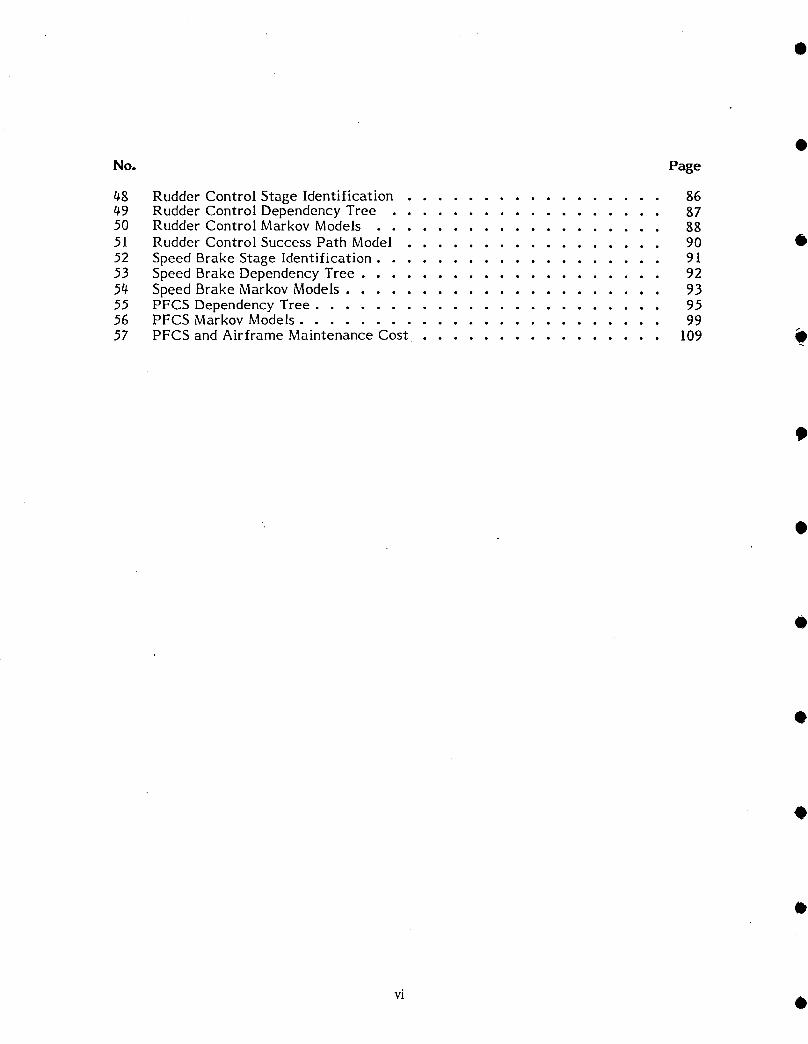
48 Rudder Control Stage Identification ................. 8649 Rudder Control Dependency Tree .................. g750 Rudder Control Markov Models ................... 8851 Rudder Control Success Path Model ................. 90 •
52 Speed Brake Stage Identification ................... 9153 Speed Brake Dependency Tree .................... 9254 Speed Brake Markov Models ..................... 9355 PFCS Dependency Tree ....................... 9556 PFCS Markov Models ........................ 9957 PFCS and Airframe Maintenance Cost ................. 109
vi •
TABLES
No. Page
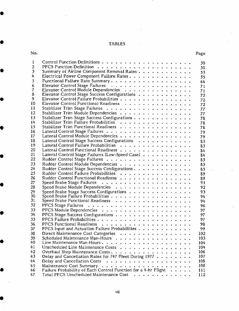
1 Control Function Definitions .................... 502 PFCS Function Definition ..................... 503 Summary of Airline Component Removal Rates ............ 534 Electrical Power Component Failure Rates .............. 555 Functional Failure Rate Summary .................. 646 Elevator Control Stage Failures .................. 717 Elevator Control Module Dependencies ............... 718 Elevator Control Stage Success Configurations ............ 729 Elevator Control Failure Probabilities ................ 72
10 Elevator Control Functional Readiness ............... 7211 Stabilizer Trim Stage Failures ................... 7712 Stabilizer Trim Module Dependencies ................ 7713 Stabilizer Trim Stage Success Configurations ............. 7814 Stabilizer Trim Failure Probabilities ................. 78
15 Stabilizer Trim Functional Readiness ................ 7816 Lateral Control Stage Failures ................... 7917 Lateral Control Module Dependencies ................ 79lg Lateral Control Stage Success Configurations ............ 8319 Lateral Control Failure Probabilities ......... ....... 8320 Lateral Control Functional Readiness ................ 8421 Lateral Control Stage Failures (Low-Speed Case) 8422 Rudder Control Stage Failures .................. 8523 Rudder Control Module Dependencies ................ 8524 Rudder Control Stage Success Configurations ............. 8525 Rudder Control Failure Probabilities ................ 8926 Rudder Control Functional Readiness ................ 8927 Speed Brake Stage Failures .................... 9128 Speed Brake Module Dependencies ................. 9229 Speed Brake Stage Success Configurations .............. 9330 Speed Brake Failure Probabilities .................. 9431 Speed Brake Functional Readiness ................. 9432 PFCS Stage Failures ....................... 9633 PFCS Module Dependencies .................... 9734 PFCS Stage Success Configurations ................. 9735 PFCS Failure Probabilities ...................... 9736 PFCS Functional Readiness .................... 98
37 PFCS Input and Actuation Failure Probabilities ............ 9938 Direct Maintenance Cost Categories ................ 10239 Scheduled Maintenance Man-Hours ................. 10340 Line Maintenance Man-Hours .................... 10441 Unscheduled Line Maintenance Costs ................ 10442 Overhaul Shop Maintenance Costs .................. 10643 Delay and Cancellation Rates for 747 Fleet During 1977 ........ 10744 Delay and Cancellation Costs ................... 10845 Maintenance Cost Summary .................... 10846 Failure Probability of Each Control Function for a 4-hr Flight ..... 11147 Total PFCS Unscheduled Maintenance Cost ............. 112
vii
• 1.0 SUMMARY
The Boeing model 747 primary flight control system (PFCS) reliability and mainte-nance study was one of five tasks of contract NAS1-14742 addressing selected
Q advanced aerodynamic and active control concept development. The study provides areliability and maintenance data base for contemporary flight controls against whichfuture applications of active controls can be assessed.
The study objectives were to define and describe the significant operational character-istics of the PFCS. As specified in the statement of work, the description included
• primary control systems (elevators, rudder, ailerons), some secondary control systems(stabilizer trim, spoilers, and speed brakes), and hydraulic and electrical power supplysystems. Autopilot actuators, which are integral with the hydraulic power controlunits, were not treated as separate components.
Two operational characteristics of the 747 PFCS were analyzed: control function• reliability, and maintenance cost. The approach to the analysis of control function
reliability was to determine component failure rates from airline data and thenanalyze these data using the CARSRA (computer-aided redundant system reliabilityanalysis) computer program. The program was developed in the ARCS (airborneadvanced reconfigurable computer system) study, contract NAS1-13654 (ref. 1), toevaluate the reliability of fault-tolerant computer systems applied to advanced flight
O _" controls. CARSRA was limited in its application to the PFCS analysis, but satisfac-tory results were obtained. The results were verified by another contractor program,CRAM (computerized reliability analysis method), as described in section 4.2.4.
The results show that for each primary control syst_n (elevator, rudder, and aileronplus spoiler) the loss of function is less than 1 x 10- during a typical 4-hr 747 flight.
• This reflects the great failure tolerance of the 747 flight controls.
PFCS maintenance cost, the other operational characteristic considered, was analyzedusing available airline data at the component level, including maintenance man-hours,material costs, and delay and cancellation rates. Both unscheduled and scheduledmaintenance costs were generated as a function of flying time.
• Mechanical flight control maintenance, which is mostly unscheduled, costs about $3.94per flight-hour. Such cost comprises 55% component overhaul, 5% line maintenance,and 40% delays and cancellations. To put such costs in perspective, the PFCS overhauland line maintenance costs are similar to costs for the automatic flight control system(AFCS) determined during the ARCS study. The PFCS delay and cancellation costs,however_ are more than l0 times those for the AFCS because of the dispatch
• criticality of primary controls. As found in the ARCS study, maintenance costs at thecomponent level vary widely between airlines because of differing airline maintenancephilosophies and operating methods.
Mechanical controls also are maintained on a scheduled basis through repeatedinspections and checks. The cost for scheduled maintenance is established at $0.19 per
• flight-hour. Scheduled maintenance probably will not be needed for active controlsystem electronics.
• 1
Scheduled and unscheduled maintenance costs_ plus reliability results and componentdata gathered from airline fleet experience 9 meet the objectives of providing theoperational characteristics of the 747 PFCS,
2 •
Q 2.0 INTRODUCTION
The model 747 primary flight control systems reliability and maintenance study was al-year effort sponsored by the Aircraft Energy Efficiency (ACEE) project office atNASA Langley Research Center. The study was one of several tasks peformed in the
6 Energy Efficient Transport (EET) element of the ACEE program.
2.1 STUDY OB3ECTIVE
• The purpose of this study was to define and describe the significant operationalcharacteristics of the model 747 primary flight control system as they relate tosystem reliability and maintenance cost. The study provided data sufficient toestablish these characteristics for a baseline contemporary flight control systemagainst which future applications of active controls technology (ACT) can be assessed.
• The model 747 was selected because it represents a current-technology airplane usingmechanical devices assisted by powered actuators for primary control in flight. Also,useful 747 operational data were available from a previous contract study (airborneadvanced reconfigurable computer system--ARCS), contract NAS1-13654 (ref. 1). Thisprevious work involved maintenance cost and reliability assessment of the 747automatic flight control system. A logical extension of this work was to evaluate
• - reliability and maintenance cost for flight control electronics and to show therelationship between these two parameters and operating philosophies for differentairlines.
The data base provided by the previous work on electronics and by this study can beapplied in the reliability assessment of a derivative 747 using ACT concepts. Suchconcepts are being developed under contract NAS1-14741, also funded through the
• ACEE project office.
2.2 PRIMARY FLIGHT CONTROL SYSTEM DEFINITION
• This study covered the mechanical portion of the flight control systems and theassociated power sources. Actuation systems for both primary and secondary controlsurfaces plus the autopilot and yaw damper actuators were included in the study.Because the actuators are integral with the hydraulic power control units in the 747,they were not considered as separate components in the study analysis. Low-speedaerodynamic devices such as the leading edge wing flaps and trailing edge wing flaps
• were not included.
Some features of the PFCS include:
o Ailerons, elevators, and rudders as primary control surfaces, with spoilers andstabilizer trim as secondary control surfaces.
@o Positioning of control surfaces using power from four independent hydraulic
systems.
• 3
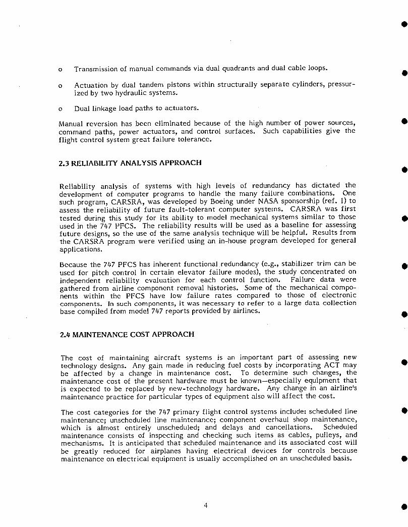
o Transmission of manual commands via dual quadrants and dual cable loops.
o Actuation by dual tandem pistons within structurally separate cylinders, pressur-ized by two hydraulic systems.
o Dual linkage load paths to actuators.
Manual reversion has been eliminated because of the high number of power sources, •command paths, power actuators, and control surfaces. Such capabilities give theflight control system great failure tolerance.
2.3 RELIABILITY ANALYSIS APPROACH
Reliability analysis of systems with high levels of redundancy has dictated thedevelopment of computer programs to handle the many failure combinations. Onesuch program, CARSRA, was developed by Boeing under NASA sponsorship (ref. l) toassess the reliability of future fault-tolerant computer systems. CARSRA was firsttested during this study for its ability to model mechanical systems similar to those •used in the 747 PFCS. The reliability results will be used as a baseline for assessingfuture designs, so the use of the same analysis technique will be helpful. Results fromthe CARSRA program were verified using an in-house program developed for generalapplications.
Because the 747 PFCS has inherent functional redundancy (e.g., stabilizer trim can be •used for pitch control in certain elevator failure modes), the study concentrated onindependent reliability evaluation for each control function. Failure data weregathered from airline component removal histories. Some of the mechanical compo-nents within the PFCS have low failure rates compared to those of electroniccomponents. In such components, it was necessary to refer to a large data collection
base compiled from model 747 reports provided by airlines. •
2.4 MAINTENANCE COST APPROACH
The cost of maintaining aircraft systems is an important part of assessing newtechnology designs. Any gain made in reducing fuel costs by incorporating ACT may •be affected by a change in maintenance cost. To determine such changes, themaintenance cost of the present hardware must be known--especially equipment thatis expected to be replaced by new-technology hardware. Any change in an airline'smaintenance practice for particular types of equipment also will affect the cost.
The cost categories for the 747 primary flight control systems include: scheduled line •maintenance; unscheduled line maintenance; component overhaul shop maintenance,which is almost entirely unscheduled; and delays and cancellations. Scheduledmaintenance consists of inspecting and checking such items as cables, pulleys, andmechanisms. It is anticipated that scheduled maintenance and its associated cost willbe greatly reduced for airplanes having electrical devices for controls becausemaintenance on electrical equipment is usually accomplished on an unscheduled basis. •
4 •

Some airlines closely monitor costs on unscheduled maintenance activity at the• component level. Cost figures for this study were obtained or generated from such
airline records. Data on costs for scheduled maintenance at the same detailed level,however 9were not available because this type of maintenance is planned and is usuallyallocated a fixed budget. Actual costs for itemized tasks are diflicult to obtain, sothe scheduled maintenance costs were estimated for the PFCS from detailed planningrequirements.
2.5 REPORT STRUCTURE
Study results are reported in three main sections. Section 4.1 describes each of the
• PFCS control functions and identifies the elements in the reliability analysis. Section4.2 brings together the system modeling, functional failure rates for the modules, anddefinitions for failure; it also presents the results of the analysis using CARSRA.Maintenance costs at the component level are assessed in section 4.3. The studyresults are summarized in section 5.0. Detailed component data used in the reliabilityand cost analyses are included as appendixes to the report.
5

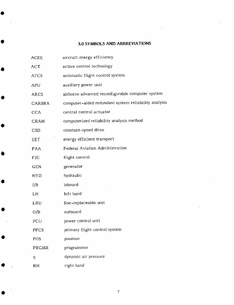
• 3.0 SYMBOLS AND ABBREVIATIONS
ACEE aircraft energy efficiency
ACT active control technology
AFCS automatic flight control system
APU auxiliary power unit
ARCS airborne advanced reconfigurable computer system
CARSRA computer-aided redundant system reliability analysis
CCA central control actuator
CRAM computerized reliability analysis method
CSD constant-speed drive
EET energy efficient transport
FAA Federal Aviation Administration
F/C flight control
GEN generator
HYD hydraulic
I/B inboard
LH left hand
LRU line-replaceable unit\
• O]B outboard
PCU power control unit
PFCS primary flight control system
• POS position
PRGMR programmer
q dynamic air pressure
0 RH right hand
• 7
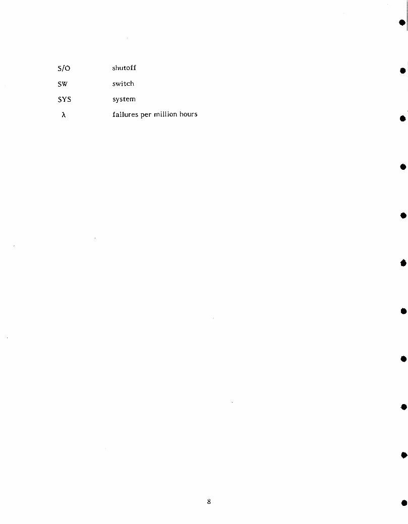
S/O shutoff
SW switch
SYS system
_ailures per million hours Q
8 •
4.0 STUDY RESULTS
The model 747 primary flight control system (PFCS) description, reliability assess-ment, and maintenance cost assessment are included in this section.
• ll.l DESCRIPTION OF MODEL 7t_7 SYSTEMS
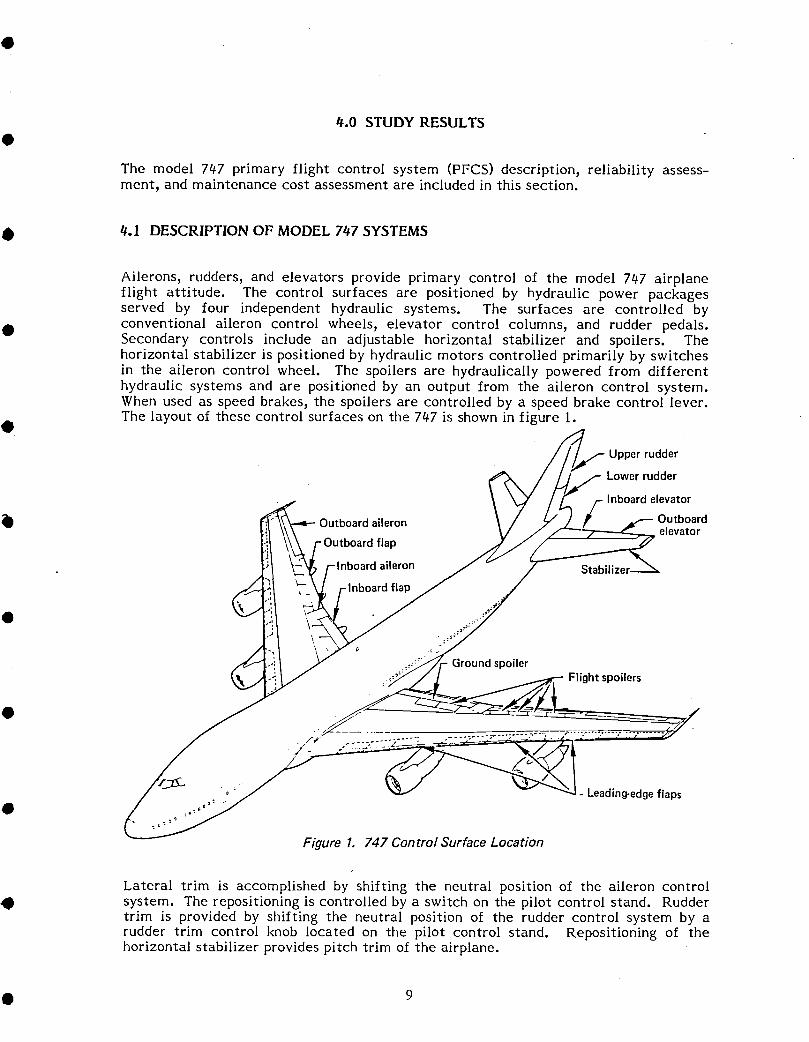
Ailerons, rudders, and elevators provide primary control of the model 747 airplaneflight attitude. The control surfaces are positioned by hydraulic power packagesserved by four independent hydraulic systems. The surfaces are controlled by
• conventional aileron control wheels, elevator control columns, and rudder pedals.Secondary controls include an adjustable horizontal stabilizer and spoilers. Thehorizontal stabilizer is positioned by hydraulic motors controlled primarily by switchesin the aileron control wheel. The spoilers are hydraulically powered from differenthydraulic systems and are positioned by an output from the aileron control system.When used as speed brakes, the spoilers are controlled by a speed brake control lever.The layout of these control surfaces on the 747 is shown in figure I.
Upper rudder
Lowerrudder
Inboardelevator
Outboardaileron Outboardelevator
flap
rdaileron
-Inboardflap
.__ Groundspoiler_:,:_/ J / _ Flightspoilers
/._:_,_"......... __-._?.:-:..---:: -.-,....... ..S.<_"
, _ _ v _J - Leading-edgeflapso_o "
Figure 1. 747 Control Surface Location
Lateral trim is accomplished by shifting the neutral position of the aileron controlO system. The repositioning is controlled by a switch on the pilot control stand. Rudder
trim is provided by shifting the neutral position of the rudder control system by arudder trim control knob located on the pilot control stand. Repositioning of thehorizontal stabilizer provides pitch trim of the airplane.
• 9

Control surfaces can also be actuated through the autopilot and yaw damper systems. •The autopilot systems control the electrohydraulic transfer valves on the autopilotmodules. The modules, which are part of the power control packages, are included aspart of the respective control system description.
Because each control system depends on its hydraulic and electrical power sources, thepower sources are described in separate sections. Functional and reliability diagrams •serve as a logical introduction to the analysis section for each system description inthe report.
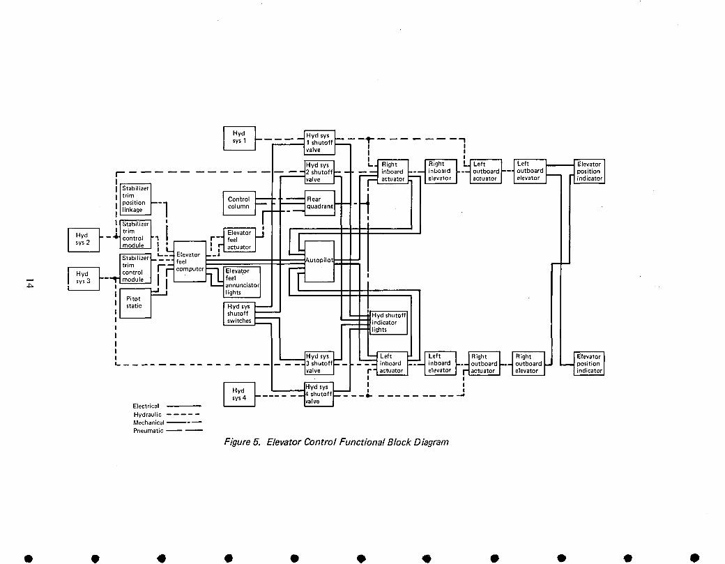
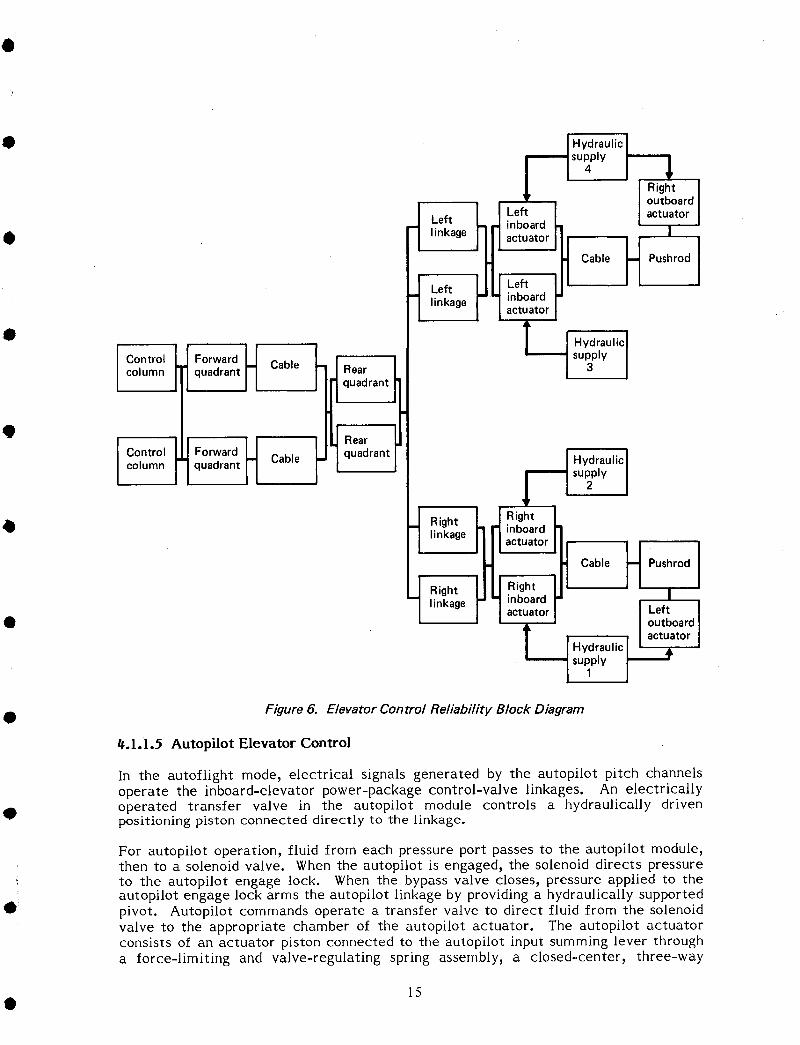
The functional block diagrams for each system define the relationships of thehardware elements to the power sources they control or that control them. Thediagrams further identily the elements necessary for the system to operate. Each •function within the system is defined by a block in the diagram; a block may representa complex piece of equiment or a simple single unit. The reliability block diagramsshow only component parts essential to the proper functioning of the system. Figure 5is an example o1 a functional block diagram and figure 6 is an example of a reliabilityblock diagram.
The following discussion is divided into seven sections dealing with" •
o Elevator control (4. I, I)o Stabilizer trim (4.1,2)o Lateral control (4,1.3)
o Rudder control (4.1.4) 6o Speed brakes (4.1.5)o Hydraulic power supply (4,1,6)o Electrical power supply (4,1,7)
4.1.1 Elevator Control
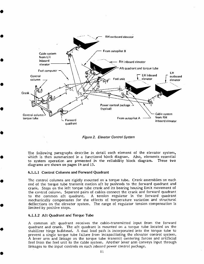
The elevator control system provides primary control of the airplane about its pitchaxis. The elevator is divided into four segments (fig. 2), each of which is positioned byhydraulically powered control units.
The system consists of pilot and copilot control columns, a forward quadrant andcrank, a common aft quadrant, cables, linkage, and four power control units. No •provision has been made for manual reversion. Artificial feel forces for the systemare obtained through a dual-feel computer control unit.
Elevator positioning is achieved by manual or autopilot actuation. Manual control isobtained from either the pilot or the copilot control column, which are linked together
mechanically. Duality is maintained with a separate cable system from each controlcolumn to the dual-linkage aft quadrant. Manual command signals from the aftquadrant to the inboard power control units (PCU) are transmitted through duallinkage. The outboard elevators are slaved to the inboard elevator outputs by a singlecable system. Autopilot input signals can be transmitted to either or both of theinboard position servos mounted within the PCU, and the pilot can select theoperational channel. Autopilot operation of either position servo causes the entiremanual control system to move, including both control columns. Pitch control can also •be achieved by changing the incidence of the horizontal stabilizer, which is describedin section 4.1.2.
q
10 •
O ................ ...._ RH outboard elevator
Cablesystem _ FromautopilotBfromLH
0 inboard " ......._'_---- RHinboardelevatorelevator
quadrantandtorquetube
Feelcomputer --_ -_--, kHControl LH inboard outboard
Feelunit _ elevatorcolumn-7 . elevatorO _ "-.../ -..,.
Crank!
Powercontrolpackage_! (typical)
Controlcolumn Cablesystemtorquetube From autopilotA from RH
u_ Forward inboardelevatorquadrant
Figure 2. Elevator Control System
The following paragraphs describe in detail each element of the elevator system,• v_hich is then summarized in a functional block diagram. Also, elements essential
to system operation are presented in the reliability block diagram. These twodiagrams are shown on pages 14 and 15.
#.I.I.I Control Columns and Forward Quadrant
• The control columns are rigidly mounted on a torque tube. Crank assemblies on eachend of the torque tube transmit motion aft by pushrods to the forward quadrant andcrank. Stops on the left torque tube crank and its bearing housing limit movement ofthe control column. Separate pairs of cables connect the crank and forward quadrantto the common aft quadrant. A tension regulator in the forward quadrantmechanically compensates for the effects of temperature variation and structural
• deflections on the elevator system. The range of regulator tension compensation islimited by positive stops.
#.I.1.2 Aft Quadrant and Torque Tube
A common aft quadrant receives the cable-transmitted input from the forwardquadrant and crank. The aft quadrant is mounted on a torque tube located on the
4D stabilizer hinge bulkhead. A dual load path is incorporated into the torque tube toprevent a single torque tube failure from incapacitating the elevator control system.A lever arm and linkage on the torque tube transmit centering forces and artificialfeel from the feel unit to the cable system. Another lever arm conveys input throughlinkages to the input controls on each inboard power control package.
• 11

#.1.1.3 Elevator Feel System Q
The feel computer is the controlling element in a hydraulically powered subsystemcomprising the computer, a feel actuator, and a feel unit (see fig. 3). The computermodulates hydraulic pressure inputs to the feel actuator in response to changes indynamic air pressure and horizontal stabilizer position. Airplane hydraulic systems 2and 3 provide the hydraulic pressure inputs Irom which Ieel pressure is derived. •
• Only feel computer /- Dynamic pressuresystem 2 is shown; / from pitotsystem 3 is identical/
Diaphragm --- / •, k%---Pilot input/_ Computed pressure \_
\\, // / from system 3 _"_,
v- p f 2_ _"_ Aft
";_IiI ' -" " . Staticiii/!/ por t /¢ ____ quadrant
: Power
Bet // Feel _ controlpackage
System 2 pressure_ \ actuator -/ \_- Centering camk \" Relief Differential pressure FEEL \-- Centering 6
FEEL valve switch CONTROL springCOMPUTER UNITFlight engineer'swarning light
Figure 3. Elevator Feel System
The computer contains two identical groups of components, each providing a separatefeel pressure input to the Ieel actuator. A pressure-differential sensing actuator inthe computer senses the pressure output of both groups of components. The actuatorcloses one of two switches if the output pressure from one group falls to about 75% ofthe output Irom the other group. Operation of either switch illuminates an ELEV •FEEL indicator light on the center instrument panel. A pressure transducer in eachcomponent group senses the diIIerence between Ieel pressure and system returnpressure, then transmits a voltage, proportional to feel pressure, to the autopilot pitchcontrol channel.
The Ieel actuator, which is mounted on the elevator feel unit, receives hydraulic •pressure inputs from the feel computer. The actuator contains two rams moving inopposite directions within a free-floating cylinder. One ram is connected to the feelunit body, which is attached to the airplane structure, and the other to the feellinkage. The Iorce exerted by the actuator is proportional to the parallel outputs ofthe feel computer; therefore, failure of one output does not aIIect elevator feel.
The feel unit transmits the force Item the feel actuator to the elevator controls. Feelpressure acts on the feel actuator rams to apply Iorce through a Y-linkage attached toa cam mounted on a pivot shaft. A lever mounted on the same shaft connects the feelunit to the elevator aft quadrant. When moving the control column in either direction,the operator must overcome the feel Iorce transmitted through the linkage to rotate
12 •
Othe cam. As the cam rotates, a roller in contact with the cam surface moves out ofdetent, displacing a lever arm held in place by two centering springs. When the pilotreleases the control column, the roller exerts pressure to center the cam, acting withthe feel pressure to return the control column to neutral. Loss of feel force is notconsidered to cause loss of the elevator control function.
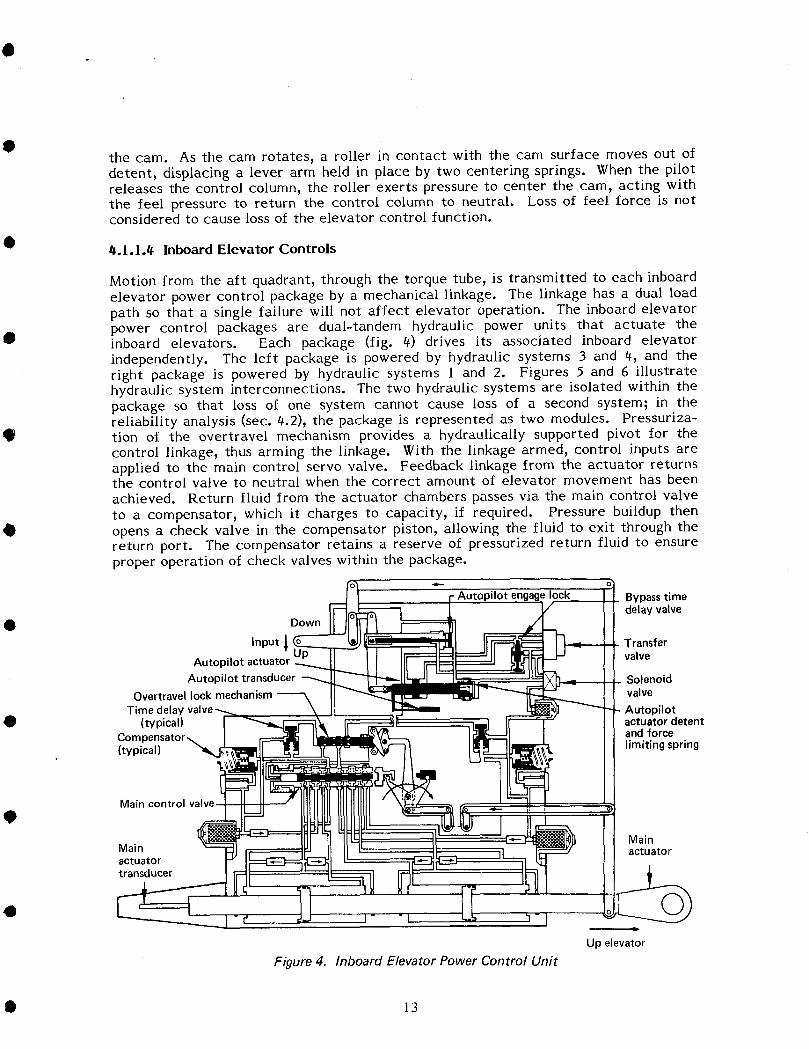
0 #.1.1.# Inboard Elevator Controls
Motion from the aft quadrant, through the torque tube, is transmitted to each inboardelevator power control package by a mechanical linkage. The linkage has a dual loadpath so that a single failure will not affect elevator operation. The inboard elevatorpower control packages are dual-tandem hydraulic power units that actuate the
• inboard elevators. Each package (fig. 4) drives its associated inboard elevatorindependently. The left package is powered by hydraulic systems 3 and 4, and theright package is powered by hydraulic systems 1 and 2. Figures 5 and 6 illustratehydraulic system interconnections. The two hydraulic systems are isolated within thepackage so that loss of one system cannot cause loss of a second system; in thereliability analysis (sec. 4.2), the package is represented as two modules. Pressuriza-
O tion of the overtravel mechanism provides a hydraulically supported pivot for thecontrol linkage, thus arming the linkage. With the linkage armed, control inputs areapplied to the main control servo valve. Feedback linkage from the actuator returnsthe control valve to neutral when the correct amount of elevator movement has beenachieved. Return fluid irom the actuator chambers passes via the main control valve
to a compensator, which it charges to capacity, if required. Pressure buildup thenopens a check valve in the compensator piston, allowing the fluid to exit through thereturn port. The compensator retains a reserve of pressurized return fluid to ensureproper operation of check valves within the package.
Autopilot lock Bypasstimedelayvalve
0 Down
Input _ Transfer
Autopilot actuator valve
Autopilot transducer Solenoid
Overtravellockmechanism valveTime delay Autopilot
O (typical) actuatordetentCompensator_ andforce(typical) "_ limitingspring
Main control valve
@Main
Main 3[ actuatoractuatortransducer
©-I
Up elevator
Figure 4. Inboard Elevator Power Control Unit
• 13
I ~~~ ~-----
IHvdl~---
Electrical
Hydraulic - - - - Mechanical ---Pneumatic -- --
1~~'nJIIII L..-_----I
I
IIII'--------
~~-
r---1,..,-_---,I Stabil izerI trimI position --1I linkage
I Stabilizer II
@] I tnmHyd - controlsys 2 module
Figure 5. Elevator Control Functional Block Diagram
• • • • • • • • • • •
S4
Rightoutboard
_ Left actuator• linkage |
Cable H Pushrod I
t Leftlinkage
1_ Hydraulic]
I COntrOl F°rwardH Cable supply Icolumn quadrant Rear
quadrant
q_ Rear
lCon,ro,orw0rOH quadrant Hydrauliclcolumn quadrant Cable
• J Right / Right /linkage
Cable H PushrodI
t Right Ilinkage I Left I• I °utb°ard I
• I actuator I
Hydraulicl II • I
supply J'_
• Figure 6. Elevator Control Reliability Block Diagram
4.1.1.5 Autopilot Elevator Control
In the autoflight mode, electrical signals generated by the autopilot pitch channelsoperate the inboard-elevator power-package control-valve linkages. An electricallyoperated transfer valve in the autopilot module controls a hydraulically driven
0 positioning piston connected directly to the linkage.
For autopilot operation, fluid from each pressure port passes to the autopilot module,then to a solenoid valve. When the autopilot is engaged, the solenoid directs pressure
i to the autopilot engage lock. When the bypass valve closes, pressure applied to the! autopilot engage lock arms the autopilot linkage by providing a hydraulically supported
0 _ pivot. Autopilot commands operate a transfer valve to direct fluid from the solenoidvalve to the appropriate chamber of the autopilot actuator. The autopilot actuatorconsists of an actuator piston connected to the autopilot input summing lever througha force-limiting and valve-regulating spring assembly, a closed-center, three-way
15
regulating valve, and an actuator=positioning detent spring, The force=limiting and •valve-regulating spring assembly provides a detent for the regulating valve and limitsthe force authority of the autopilot actuator, This force limitation ensures thatmanual control column inputs can be applied to override autopilot inputs, if necessary,The autopilot actuator operates the linkage to position the main control valve,initiating main actuator response,
A linear transducer connected to the autopilot actuator signals the position of theactuator to the autopilot pitch control channel, A linear transducer connected to thedual-tandem main actuator provides a feedback signal to the autopilot pitch controlchannel to close the servo loop,
tF.l.l.6 Outboard Elevator Control •
The mechanical control to each outboard-elevator power-control package is trans-mitted mechanically through a slave system from the opposite inboard elevator. Apushrod connected to the front spar of the inboard elevator operates an inboardquadrant, which is connected by cables to the opposite outboard quadrant. A pushrodfrom the outboard quadrant connects to the input linkage of the outboard elevatorpower control package. No hydraulic or mechanical connection exists between •outboard and inboard packages on the same side. The left outboard package ispowered by hydraulic system l; the right outboard package is powered by hydraulicsystem 4.
_. I. 1.7 Surface Position Indication
A control surface position transmitter, connected to each outboard elevator, transmitselectrical signals to a control surface position indicator in the control cabin. Theindicator is a composite instrument that shows the positions of the outboard elevators,ailerons, spoilers, and rudders. Functional and reliability block diagrams are shown inFigures 5 and 6 on pages 14 and 15.
t_.l.2 Stabilizer Trim
The stabilizer control system (fig. 7) uses a linear, ball-screw actuator, driven by twohydraulic motors, to pivot the stabilizer about its rear attachments to the empennagestructure. A gimbal mounting attaches the lower end of the mechanism to theempennage structure. A ball nut, driven by the jackscrew, connects to the stabilizer Qthrough the upper gimbal attachment. Two independent modular control packagesdirect hydraulic power to the trim drive mechanism.
The system provides four modes of stabilizer trim control: three electrical modes, andan emergency manual-mechanical mode. The electrical modes permit manual-electricactuation by either the pilot or copilot or automatic actuation by the autopilotsystems. The open-loop control system is designed to prevent trim in opposition to thedirection commanded or runaway trim. Functional and reliability block diagrams forthe stabilizer trim are shown on pages 21 and 22 in the following detailed description.
16 •

B Stabilizertrimcontrol
Dual switchesmanual
levers (arm)
(control)(arm) Hydraulicsystemshutoff
O switchesPosition indicatorand travel limit
quadrant
OStabilizerPosition and %
motion Hydraulicindicators Brake
Stabilizer trim _" _- -- Stabilizer limitinterface unit _l_ switches (typical)Q To
autopilot
Stabilizertrim drivemechanism
Hydraulic
motor
Controlmodules
Figure 7. Stabilizer Trim System
#.1.2.1 Stabilizer Trim Control Switches
Duplicate control switches_ located in the pilot and copilot control wheeJs_actuate thestabilizer trim systems in the manual-electric control mode (see fig. 7). The twosegments in each switch are mechanically and electrically isolated from each other.
• Each segment operates a pair of solenoids on each control module. One segmentcontrols a pair of arming solenoids and the other controls a pair of directional controlsolenoids. Because both an arming solenoid and its associated directional controlsolenoid must be energized to trim the stabilizer, both segments must be held in thesame direction to initiate movement. This ensures that a malfunction in a singlesegment of the circuit cannot cause a runaway stabilizer.
e0.1.2.2 Autopilot Stabilizer Control
The autopilot control mode is connected through two separate dual-channel systems (Aor B), which operate the arming and control valves of the hydraulic modules. Duringcruise, only one channel is used, but both channels may be switched on during landing.
• In this mode, the first channel is operative and the second is armed and in a standbystate. If the first channel malfunctions, control is automatically transferred to thestandby (second) channel.
17O

If there is disagreement between the arming or control circuits and the secondaryhydraulic brake pressure switch, the autopilot warning light will come on 3 sec after tthe disagreement occurs. The warning light also comes on if a 12-sec out-of-trimcondition occurs.
The autopilot mode has no authority over any other mode. When the autopilot is inoperation and a signal is generated by the thumb switches, the autopilot channeldisengages. •
0.1.2.3 Stabilizer Trim Limit Switches
In the electrical control modes, limit switches prevent the stabilizer from movingbeyond the positions required by the normal flight envelope for the prevailingoperating condition. Travel limit and warning horn switches are mounted outboard on •the aft face of the actuator bulkhead. Cams attached to the stabilizer front sparactuate the switches. One pair of switches limits travel in the manual-electric controlmode and two pairs limit travel in the autopilot control modes (one pair for eachautopilot channel).
The trim system contains an elevator-operated trim cutoff that is operated by •switches in the elevator control system. Two pairs of micro switches on the structurebeneath the control cabin are actuated by the elevator forward quadrant. Twoswitches are operated by the control column in the elevator up direction, and two bymovement in the elevator down direction. The switches operate relays in thestabilizer trim interface. The relays interrupt electrical commands to the stabilizer ifthe control column is moved more than 5.5 deg from neutral in a direction opposed to •the trim. The signal path commanding trim in the opposite direction is left intact.
t_.1.2.4 Stabilizer Trim Levers
Two levers on the pilot side of the control stand actuate the system in the manual-
mechanical control mode. The levers perform essentially the same functions as the •stabilizer trim switches, but they operate through separate mechanical systems. Theright lever operates an arming servo valve in each modular control package, and theleft lever operates a control servo valve in each package.
Both levers must be moved in the same direction to trim the stabilizer. This ensures
that a runaway trim cannot occur if a malfunction jams one lever in either direction. •The dual control levers exercise complete authority over all modes. Thus, completecontrol is achieved by the hydraulic module servo valves, which hydraulically interruptany other trim signal when the levers are operated.
In the mechanical control mode, a cable system shuts off power to the hydraulicmotors before the mechanical stops are reached. Mechanical control permits travelbeyond the electrical limits to satisfy all performance requirements. Mechanical stops •on the jackscrew limit absolute travel, but the trim system does not normally drive thestabilizer to the stops.
_.1.2.5 Hydraulic Power
Airplane hydraulic systems 2 and 3 supply power for the stabilizer trim system. Each •system supplies power to an independently functioning group of components. Eachgroup of components consists of a modular control package, hydraulic motor, andhydraulic brake. Hydraulic system 2 supplies the left component group, whilehydraulic system 3 supplies the right component group.
18 •
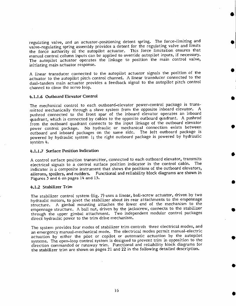
• 4.1.2.6 Hydraulic Modules
Two identical modules consist of an arming valve, control valve, two manuallycontrolled servo valves, four dual-wound, solenoid-operated valves, a rate controlvalve, motor-operated shutoff valve, and a secondary brake pressure switch (fig, 8), Amotor shutoff valve upstream of the rate control valve in the pressure line is operated
0 by a switch located on the aisle stand in the control cabin, The rate control valve,which is a spool valve positioned by a "Q" bellows-linkage assembly, controls theoutput of the hydraulic motor and the stabilizer trim rate,
When the trim has been selected in either direction, hydraulic fluid enters each modulethrough integral check valves to the rate control valve, which regulates the fluid flow
• rate in proportion to aircraft speed. The flow, which is directed by the arming andcontrol up or down solenoid, continues through the arming and control service ducts.The solenoids direct the flow to the arming valve and the control valve.
When energized, each solenoid releases pressure from a balance cylinder at one end ofits corresponding valve. Pressure exerted by the opposite solenoid on the other end of
• the valve drives the valve to the end of its travel in the selected direction.
With both the up and down solenoids deenergized, the valve is pressure-balanced andspring-loaded to the center neutral position. With both the arming and control valvespositioned to command trim in the same direction, fluid is directed through outletports to the trim drive mechanism. Fluid cannot flow if only one valve is positioned
directionally.
------_ To elevator feel computer (2 places)Hydraulic_ ^
system 3
Stabilizer jackscre 7
Right control module Cablesto dualmanual
• leversHydraulic
Shutoff valve - brake
Left control module
• I t'€_-I Solenoid valves
4B PressureHydraulic switchsystem 2
" _ ,-- To brake pressure lightFlight control To stab LToshutoff valve trim airspeed - To stabilizer trim switches
(2 places) cutout Rate control valve (controller)• switches
Figure 8. Stabilizer Trim Control Modules
19
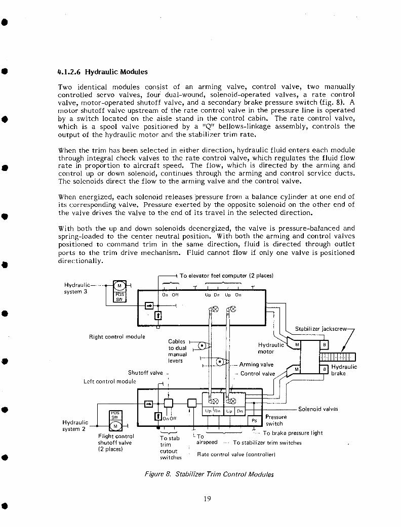
t1.1.2.7 Stabilizer Trim Drive Mechanism •
Two hydraulic motors convert hydraulic pressure to rotary motion to drive ajackscrew. The drive mechanism (fig. 9) also includes two hydraulic secondary brakes,a primary brake, diilerential, bull gear, and ball nut.
Secondarybrakes 0,
q Jackscrew
gear Uppergimbal •housing Ballnut
, \
Differential
= BPrimarybrakehousing
Hy 1motors
Lower _ Mechanicalstop_'_, .gimbal _.
Safetyrod
Figure 9. Stabilizer Trim Drive Mechanism •
Each combination of motor and brake, activated by its associated modular control
package, can control stabilizer movement independently through the differential. Innormal operation, however, the two combinations act together. Each motor is a nine-cylinder, piston-type, reversible unit. The differential, a dual load path from input to •output, is bolted to the bull gear housing.
The bull gear housing contains a spur gear splined to the jackscrew. To prevent thestabilizer iront attachment from failing if the jackscrew fails, a safety rod is inserted
lengthwise through the jackscrew. The safety rod is held in place by a safety nut atthe top of the rod and a safety sleeve and shaft at the bottom. •
The jackscrew drives a ball nut consisting oi a primary and a secondary nut splinedtogether and joined by a bolted, mating flange. Ball bearings circulate within theprimary nut and through two external ball return tubes to transmit the drive from thejackscrew to the upper, primary nut.
The ball nut achieves its loading duality through two ball circuits. Only one of the two •ball circuits is loaded. I_ this circuit fails, the second ball circuit carries the load.The lower, secondary nut carries loads only if a primary nut or gimbal yoke fails.
20

I Hydrualic _ Hydraulicsystem2 "1 motor --
I I - Cohere,28V dc .... module brakeArm "- --
__ Arm __ leverswitch
(2) I
___Oontro, C°ntrol_t 1switch lever Mechanical
,2) t limit l _--_Ll Stabilizer
! °°""°nL___ Autopilot Hydraulic - Brake indicator
Limit interface shutoff I release -switcheshJ
box switches • I l lights Stabilizer
positionindicator
Autopilot Pitot- --"
I static
_-_ Elevator- _ -I Elevator controlled Control Hydraulicsystem limit switch module motor
I t ' qHydraulic _1Electrical system3 HydraulicMechanicals- _ brake ""HydraulicPneumatic
Figure 10. Stabilizer Trim Functional Block Diagram
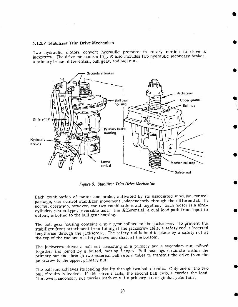
A B
Arm/ I Icontrol lC°ntr°l I IControllever r_ module I I module Ill
II (hydraulic)lI (hydraulic)_1,I ill i IIc°_,o] I_a",,° s.,,to.IIs.u.o. •
I L I IHydraulicI IHydrauliccontrolArm/ I-Im°t°rI Im°t°rswitch, •
,o,e [jIIllli Hydraulic Hydraulic
Limit "1 brake I I I brake
I •1 I
Arm/ Arm/ rr earycontrol controlswitch, switch,open open
i, i ttRelay Relay
I " I
I i I GearboxImodule module differential
(electrical) (electrical) I II
I I
Control I"a" I s"c°nImodule nut dary(mechanical nut •I I
II I
iJac-LI IA B screw screw
I I •I
Figure 11. Stabilizer Trim Reliability Block Diagram
The primary and secondary brakes prevent the stabilizer from creeping when it isstationary. The primary brake is applied by the thrust exerted on the jackscrew by •stabilizer air loads. Downward thrust compresses the lower brake disk of the primarybrake between the flange and the lower ratchet. Because the jackscrew is right-hand

threaded, downward thrust exerts pressure to turn it clockwise (viewed from the driveend). But two diametrically opposed pawls prevent the lower ratchet from turningclockwise, thus constraining the screw. Upward thrust exerted on the screwcompresses the upper disk and applies counterclockwise torque, which is similarlyresisted by the upper ratchet. The actuator drive that trims the stabilizer in adirection opposed to air-load thrust is unresisted, because the ratchet and compressed
• brake disk rotate freely with the flanged screw shaft. Drive in a direction with thethrust is opposed by the primary brake. The hydraulic motors, assisted by the thrustexerted by the air load_ overcome brake friction to trim the stabilizer in thisdirection. The hydraulic brakes and control valves provide secondary braking byhydraulically locking each motor when no trim signal exists.
• t_.l.2.g Stabilizer Position Indication
Two BRAKE release lights and two STAB TRIM lights indicate the operating status ofthe system. The BRAKE release lights are mounted on the control stand to the rightof the throttles in the control cabin. The remaining lights, the autoflight systemannunciator lights, are located on the forward center instrument panel.
A stabilizer position indicator dial is located on each side of the control cabin aislestand. The dial is connected directly to the stabilizer by a cable system that transmitsthe stabilizer position to the dial needle. In addition to the dial indicator, thestabilizer operation is also indicated by rotating wheels with color bands and anaudible generator indicator. Each dial has a green band that shows the safe range for
• the stabilizer trim position during takeoff.
Functional and reliability block diagrams are shown in Figures I0 and II on pages 21and 22.
_.I.3 Lateral Control
Lateral control of the airplane is provided by two ailerons in each wing and by thespoilers (see fig. 12). The ailerons are hydraulically powered using all four airplanehydraulic supply systems.
The ailerons are controlled by conventional control wheels interconnected with drumsand cables below the control columns. The control cables connect the drum at the
• pilot control column to a cable quadrant in the left wing-gear wheel well. Thequadrant includes a trim mechanism and also provides artificial feel to the aileroncontrol system. The trim and feel mechanism provides input to the hydraulicallypowered left and right central control actuators, which also receive input from theairplane autopilot system.
• The mechanical input to the central control actuators moves internal control valves,which causes the actuators to provide a hydraulically powered output. The upperpiston rod of each actuator is connected to a spoiler differential that controls the fiveflight spoilers in the respective wing. The lower piston rod of each actuator isconnected to an aileron programmer that transmits the output by cable to therespective wing. The cables are attached to an aileron power-package control
• quadrant at each control surface. The outboard ailerons, which are used for low-speedoperation only, are isolated from the aileron system by a lockout mechanism. Thelockout mechanism prevents the outboard ailerons from operating when the outboardflaps are fully retracted. It is engaged by an electric actuator that receives power
• through a flap-actuated switch.
• 23

Inboard flight-spoilers _ Lost-motion device Ground spoiler
Ground spoiler _] _ _ Inboard flight- spoilers
Outboard ,_ ._ _ / /_-----Outboardb/ \ flight-
flight-spoilers 8 9 10 1,F _ spoilers
I Ground ] Spoiler mixerTrim, centering, Speed brak spoiler (LH and RH)
and feel unit _ sequence control Lost-motion quadrantmechanism valve
t_J
Central control Input bus rodactuator (2 places) and load limiter -- Transfer valve (2 places)
-------_ Aileron programmerLockout device Backdrive rod (2 places)
r- _ Power control Output bus rodunit (typical) and load limiter
I ! ! device
L.___ Inboard
_ Outboard aileronaileron Positiontransmitter(4 places)
Figure 12. Lateral Control System
• • • • • • • • • • •
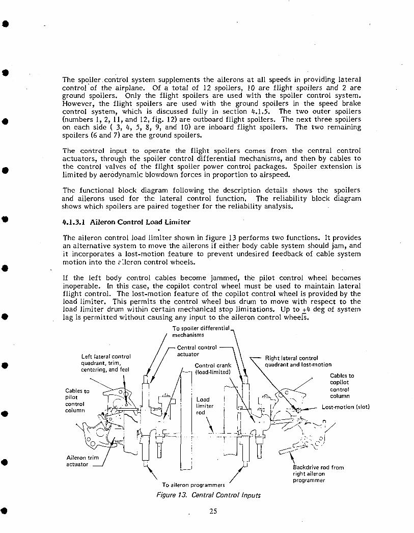
The spoiler ..control system supplements the ailerons at all speeds in providing lateralcontrol of the. airplane, Of a total of 12 spoilers) 10 are flight spoilers and 2 are ..ground spoilers, Only the flight spoilers are used with the spoiler control system,However) the flight spoilers are used with the ground spoilers in the speed brakecontrol system) which is discussed iully in section 4,1,5, The two outer spoilers
• (numbers 1, 2) 11, and 12, fig. 12)are outboard flight spoilers. The next three spoilerson each side (3) 49 5, 8, 9) and 10) are inboard flight spoilers. The two remainingspoilers (6 and 7) are the ground spoilers.
The control input to operate the flight spoilers comes from the central controlactuators, through the spoiler control differential mechanisms, and then by cables tothe control valves of the flight spoiler power control packages. Spoiler extension islimited by aerodynamic blowdown forces in proportion to airspeed.
The functional block diagram following the description details shows the spoilersand ailerons used for the lateral control _unction. The reliability block diagramshows which spoilers are paired together for the reliability analysis.
0.1.3.1 Aileron Control Load Limiter
The aileron control load limiter shown in figure 13 performs two functions. It providesan alternative system to move the ailerons if either body cable system should jam, andit incorporates a lost-motion feature to prevent undesired feedback of cable systemmotion into the _'leron control wheels.
If the left body control cables become jammed, the pilot control wheel becomesinoperable. In this case, the copilot control wheel must be used to maintain lateralflight control. The lost-motion feature of the copilot control wheel is provided by theload limiter. This permits the control wheel bus drum to move with respect to theload limiter drum within certain mechanical stop limitations. Up to +# deg of system
• lag is permitted without causing any input to the aileron control wheel.
To spoiler differential_
mechanismsCentral control --_
Left lateralcontrol actuator \ _ Rightlateralcontrolquadrant trim
B ' " ' r Controlcrank _ _ _ quadrant andlost-motioncentering,andfeel -- (loadlimited) 1= \t , -I " , . Cablesto
i / ! \ / copilotCables to _'>_k-_ i , / ! I -_ I _ control
pilot _'_--_ _(' I J _-_ ]Load i ) I r "-Et-_L-\Ok_"_ '? column
c°[_utr__ .1_...__ _ !r _ Ir_d'ter i [ _ _. //. _._-Lost-mot,on(slot)
. - - r_: -'j _-_ r,
Aileron trim / I U , L_---J _ U '_,i."_
• actuator _ L._ __j 4f_.J Backdrive rod from
X / right aileronprogrammerTo aileron programmers
Figure 13. Central Control Inputs
• 25
@_.1.3.2 Aileron Trim and Feel Mechanism
The aileron trim and feel mechanism (fig. 13) provides artificial feel at the aileroncontrol wheels. It also centers and trims the lateral control system. The mechanismreceives its input from the left body control cables and provides an output to operatethe central control actuators. •
Trim input to the mechanism is provided by a trim actuator. The actuator consists ofan electric motor and jackscrew that provide linear motion of the output shaft. Theactuator is controlled by switches on the pilot control stand; the actuator output shaftis connected to the mechanism support assembly. Output of the actuator establishes a
new control system neutral position by repositioning the entire trim and feel •mechanism, including the input quadrant. Such rotation provides an input to thecentral control actuators, which position the lateral flight control surfaces to give thedesired trim correction. Rotation of the input quadrant in response to trim input alsorepositions the aileron control wheels away from the normal neutral position.
The trim actuator position is not affected by reverse forces resulting from normalcontrol of the system. Loss of the feel and trim system will not cause loss of thelateral control function.
4.1.3.3 Central Control Actuators
The aileron programmers and spoiler differentials are operated by two mechanicallyconnected central control actuators. The actuators receive lateral control input and •provide a hydraulically powered output to operate the programmers and differentials.Hydraulic pressure is provided to the left actuator from systems 1 and 2. Hydraulicsupply systems 3 and 4 provide power for the right actuator. The actuators alsoinclude provisions for input from the autopilot system.
Mechanical input to each actuator is transmitted through dual load path cranks to the •primary and seconary summing levers (fig. 14). The primary summing lever isconnected directly to the spool of the main control valve. The valve is a dual tandemvalve with the valve sleeve connected to the secondary summing lever.
During normal operating conditions, the sleeve is rarely repositioned. Motion of thevalve spool or sleeve directs hydraulic fluid from both supplying systems to a tandem •actuator that provides the input to the spoiler differential and aileron programmer.The summing levers, which are connected to the actuator, provide the follow-upmotion to close the control valve when the actuator reaches the desired position.
Autopilot components within the actuator include a solenoid valve, electrohydraulicservo valve, autopilot cylinder bypass valve_ autopilot actuator, and two linear •transducers. During manual operation using the aileron control wheels, hydraulic fluidin the autopilot actuator circulates, preventing a hydraulic lock and allowing thesumming levers to move. Autopilot operation is accomplished by electrical signalsapplied to the transfer valve, which controls the flow of hydraulic fluid to theautopilot actuator. When the autopilot actuator is moved, the main electrohydraulicservo valve is positioned through the summing levers. From .this point, functioning is •identical, irrespective of the mode of operation (manual or autopilot). Movement ofthe tandem actuator, transmitted through the summing levers, provides the feedbacksignal to the main control valve. Autopilot feedback signals are provided by lineartransducers positioned by the autopilot actuator and the tandem actuator.
26 •

_1 Overridepiston
/ Autopilot bypassvalveJ
OVERRIDE-- Autopilot shaftroller
B Overridepiston Transfervalve
Transducer Solenoidvalve
Filter
Autopilot actuator (3 places
Main control valve --
• Input lever
Summinglever
Thermo valve
Output actuator
• T oaileron _] [_ Tospoiler
q_ Transducer
Chec Pivotpoint(5 places)
• Figure 14. Central Control Actuator Schematic
Spring detents, force limiters, and lost-motion features permit system operation if acomponent fails. A spring detent is located on the input link to each central controlactuator. In the event of jamming within an actuator, the link disengages in response
• to a small aileron control wheel movement, permitting full valve travel in thealternate actuator. In either control system, any jamming that may occur between anaileron control wheel and the control actuator is bypassed by the aileron control loadlimiter. The spring force is overcome in the limiter, permitting the left body cables tooperate even though the right body cable system is jammed. In this condition, thesystem can be operated by the pilot control wheel. If the left body cable system jams,
• the system can be operated by the copilot control wheel through the right body cables.If the hydraulic system within one actuator fails completely, the related programmerwill not move. The opposite central control actuator, however, will respond to a signalby moving its programmer and providing the input to override the force-limiting rodbetween the programmers. This permits the aileron to be operated on the same side Ofthe airplane as the operable central control actuator.
#.1.3.# Aileron Programmers
The aileron programmers control the motion of the ailerons relative to movement inthe aileron control wheel. Two programmers are installed, one on each wing, witheach programmer providing the output for its respective wing. The programmers are
• designed to produce a relatively large amount of aileron travel from an initial rotationof the control wheel away from neutral. The aileron response rate decreases ascontrol wheel rotation increases.
27O

#.1.3.5 Aileron Power Packages •
Each of the four ailerons is positioned by a single aileron power package, as shown infigure 15. Two independent hydraulic supply systems provide hydrauic fluid to eachpackage. They are isolated within the package so that with the loss of one system thepackage will continue to operate. For reliability analysis, the power package isrepresented as two separate modules, each with its own hydraulic supply system. Q
Input to each power package is provided by a control linkage and cable runs that arepositioned by one of the central control actuators. The input operates through anovertravel mechanism to position a single-spool tandem control valve. The overtravelmechanism compensates for additional input after the valve spool has reached fulltravel. •
Hydraulic fluid from the supply systems is provided to the control valve through filtersand check valves that prevent reverse flow in the pressure lines. Positioning of thecontrol valve ports both hydraulic systems to a tandem actuator. As the actuatormoves to position the aileron, it also repositions the input linkage to the powerpackage. The follow-up motion closes the control valve when the aileron reaches the •desired position as determined by the initial input. If the linkage fails, a bias springpositions the control valve spool to the aileron full-down position.
Overtravel_ mechanism Tandem valve
Input I
Biasspring
Compensator
0 Thermostaticflow valve
Linkage Aileron hydraulic system •assembly Left inboard 1 & 3
Right inboard 2 &4..... Left outboard 1 & 2
................ Right outboard 3 & 4
Controlsurface •
Figure 15. Aileron Power Control Unit Actuation
t_.1.3.6 Outboard Aileron Lockout System
An outboard aileron lockout mechanism in each wing isolates the outboard aileronsfrom the lateral control system during high-speed flight. The mechanism consists of a •housing_ cable quadrant, input crank, output crank, and a series of levers and links.When the components are in certain positions, the mechanism either transmits or
28 •

tlt prevents the transmission of motion from the control wheel to the aileron powerpackage. The outboard aileron electric lockout actuator provides the input to theaileron lockout mechanism. The actuator consists of a 28V dc reversible motorcontrolled by limit switches within the actuator plus an actuator shaft. Electricalpower to the actuator is provided through a switch actuated by the outboard trailingedge flap power package,
#, 1.3.7 Spoiler Control Differential Mechanisms
Two differential mechanisms, located on the forward wheel well bulkhead, combinethe inputs from the central control actuators and the speed brake sequence mechanismto position the flight spoilers (fig. 16). The differential mechanisms allow the flight
• spoilers to be used to augment lateral control of the airplane, even when simultane-ously being used as speed brakes. Each differential mechanism includes a lateral inputshaft and a speed brake input shaft plus a right and left output shaft with cablequadrants for cable control inputs to the spoilers.
Spoilerdifferentiali• Downand
locked Ground
Inflight speedspeed brakebrake full up ' Flightspoiler
assemblies(10p
• Groundspoilerassys(No6&7) ' _--6 7
Position 5 8transmitter(2places)
4
3 10Speedbrakesequence
2 mechanism Groundspoilercontrolvalve 11
1 Hydraulic• system4 12
Figure 16. Spoiler Quadrant Schematic0
The differential mechanism housing contains the spoiler programming cam plus relatedlevers and linkage, Rotation of the cam programs the lateral control to the spoilers bycausing the output cable quadrants to be rotated differentially.
Only a speed brake input to the differential mechanism will raise the flight spoilers on• both wings in proportion to actual speed brake input. Simultaneous inputs from aileron
and speed brake systems will cause the output quadrants to move in a combinedmanner, providing lateral control from the flight spoilers with the speed brakes on.
• 29

_.1.3.8 Spoiler Power Control Packages 9
Each flight spoiler power package includes a cable quadrant and linkage for conveyingthe control input to the control package valve. Certain spoilers are grouped togetherfor simultaneous operation by common cable runs from the differential mechanisms(fig. 16). One cable quadrant of the left differential mechanism controls spoilers 3, #,and 5; the other controls spoilers 8, 9, and 10. One cable quadrant of the right •differential mechanism controls spoilers 1 and 2 and the other cable quadrant controlsspoilers l l and 12.
#.1.3.9 Spoiler Position Indication
Surface position transmitters are installed at spoiler # on the left side and spoiler 12 •on the right side. The two transitters provide electrical signals to the positionindicator in the control cabin, showing relative displacement and position of the twospoilers. The maximum up position for all flight spoilers is #5 deg, except for spoilers5 through 8, which is 20 deg.
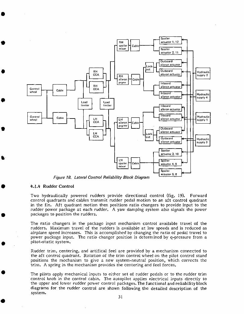
Functional and reliability block diagrams for the lateral control system are shown in •Figures 17 and 18.
I I _ -- -- -- sys 3indicating ] "1 I q
I J Hydraulic •'-'--I ' '; I.... | sys2
IHW.I sys" t Sp_er p , I Hydraulic' ' , r- -'I ,y,4 _j ,o_,o?o.I
I, l__ II ........... I
mixer •
-C( Aileron
programmer
mixer
"1 .
L_._I •[Po,,,,o,-,n0,ca,,o0,sys4,• t" Orau"olElectrical _jl-- "_ sys2
Mechanical -- - --
Hydraulic ..... -- -- Hydraulicsys3 •
Figure 17. Lateral Control Functional Block Diagram
30
_ Spoiler ]_@ _1 mixer I [_-J_ actuator 1,12
Spoileractuator2, 11
I aOlUetr%O2radtuatoraileron actuator I supply 2
lainlbr°ardactuator J4"--
lainlber°°ardactu at° r _I--a..... ,nboard
I I- ) Inboard
_ aileron actuator
• L _ _ I routboard _
a,eron actuatorU Outboard
-- --Iaileronactuator|
_ Spoiler
actuator 3, 10
_ Spoiler
/
actuator 4, 9
Spoiler _1_actuator 5, 8 .
Figure 18. Lateral Control Reliability Block Diagram
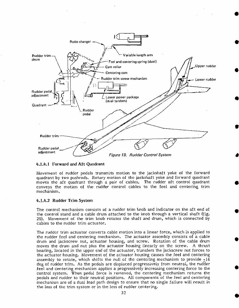
• #.l.# Rudder Control
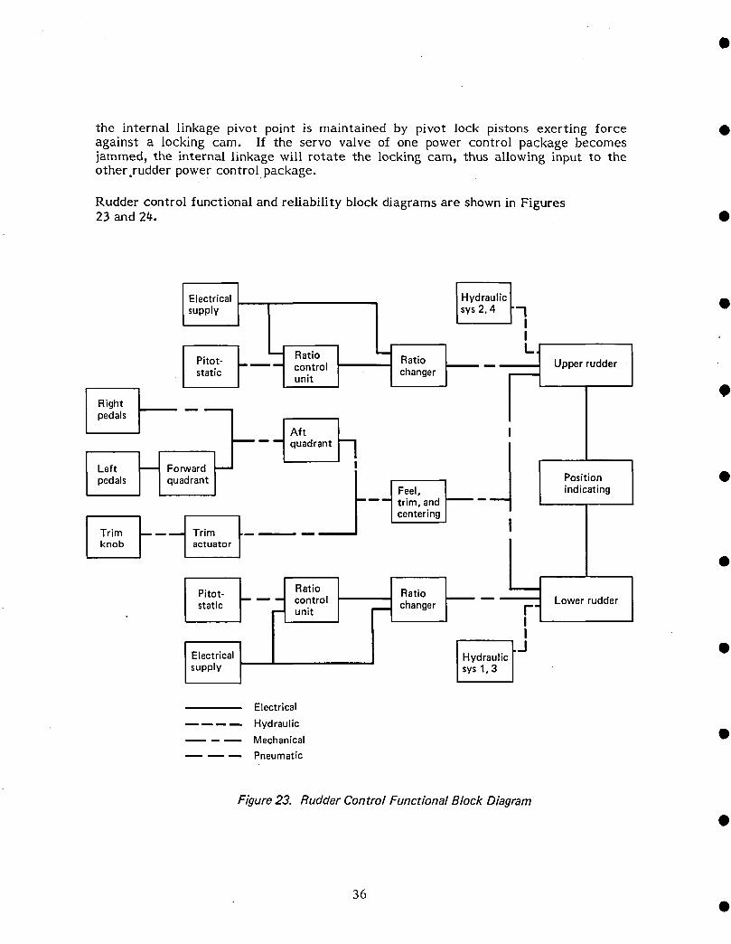
Two hydraulically powered rudders provide directional control (fig. 19). Forwardcontrol quadrants and cables transmit rudder pedal motion to an aft control quadrantin the fin. Aft quadrant motion then positions ratio changers to provide input to therudder power package at each rudder. A yaw damping system also signals the power
• packages to position the rudders.
The ratio changers in the package input mechanism control available travel of therudders. Maximum travel of the rudders is available at low speeds and is reduced asairplane speed increases. This is accomplished by changing the ratio of pedal travel topower package input. The ratio changer position is determined by q-pressure from a
• pitot-static system.
Rudder trim, centering, and artifical feel are provided by a mechanism connected tothe aft control quadrant. Rotation of the trim control wheel on the pilot control standpositions the mechanism to give a new system-neutral position, which corrects thetrim. A spring in the mechanism provides the centering and feel forces.
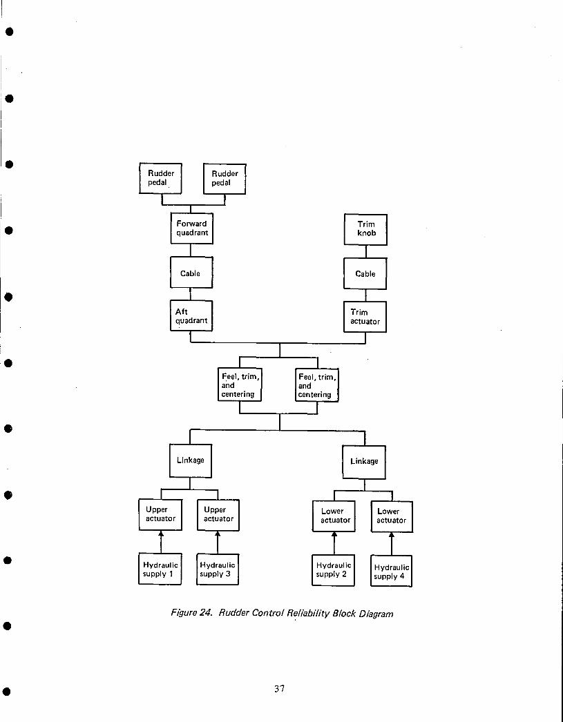
• The pilots apply mechanical inputs to either set of rudder pedals or to the rudder trimcontrol knob in the control cabin. The autopilot applies electrical inputs directly tothe upper and lower rudder power control packages. The functional and reliability blockdiagrams for the rudder control are shown following the detailed description of thesystem.
31@
II
Rudder trim f
Rudder pedal_ _
adjustment Figure 19. Rudder Control System
4.1.4. I Forward and Aft Quadrant
Movement of rudder pedals transmits motion to the jackshaft yoke of the forwardquadrant by two pushrods. Rotary motion of the jackshaft yoke and forward quadrantmoves the aft quadrant through a pair of cables. The rudder aft control quadrant •conveys the motion of the rudder control cables to the feel and centering trimmechanism.
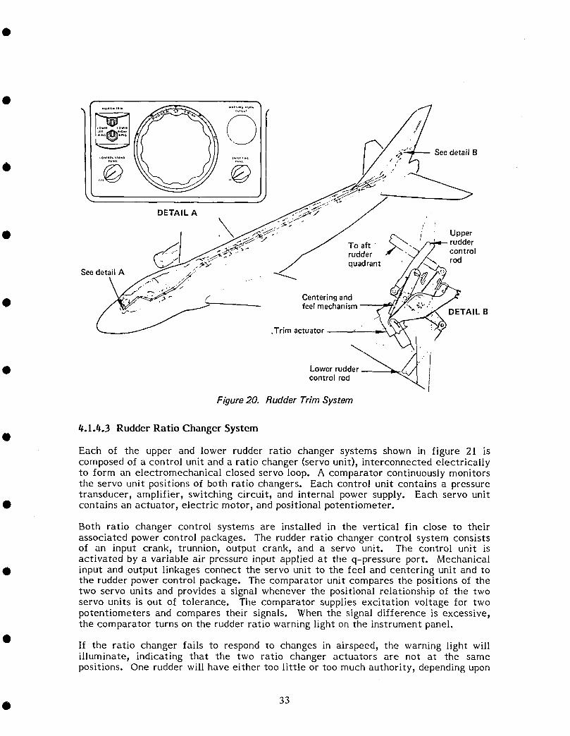
#.1.#.2 Rudder Trim System
The control mechanism consists of a rudder trim knob and indicator on the aft end of •the control stand and a cable drum attached to the knob through a vertical shaft (fig.20). Movement of the trim knob rotates the shaft and drum, which is connected bycables to the rudder trim actuator.
The rudder trim actuator converts cable motion into a linear force 9which is applied tothe rudder feel and centering mechanism. The actuator assembly consists of a cabledrum and jackscrew nut, actuator housing, and screw. Rotation of the cable drum •moves the drum and nut plus the actuator housing linearly on the screw. A thrustbearing, located in the upper end of the actuator, transfers the jackscrew nut forces tothe actuator housing. Movement of the actuator housing causes the feel and centeringassembly to rotate, which shifts the null of the centering mechanism to provide +16deg of rudder trim. As the pedals are displaced progressively from neutral, the rudderfeel and centering mechanism applies a progressively increasing centering force to the •control system. When pedal force is removed, the centering mechanism returns thepedals and rudder to their neutral positions. All components of the feel and centeringmechanism are of a dual load path design to ensure that no single failure will result inthe loss of the trim system or in the loss of rudder centering.
32 •
.................... See detail B*,_,L ,,_*
Q" ...... / _-.._ _'_'_J
DETAIL A .
\• Upperruddercontrol
f rudder rodJ quadrant
See detail A _
/ Centering andfeelmechanism
DETAIL B
Trim actuator
/d
• Lowerrudder_ I
controlrod iFigure 20. Rudder Trim System
_.1._.3 Rudder Ratio Changer System
Each of the upper and lower rudder ratio changer systems shown in figure 21 iscomposed of a control unit and a ratio changer (servo unit), interconnected electricallyto form an electromechanical closed servo loop. A comparator continuously monitorsthe servo unit positions of both ratio changers. Each control unit contains a pressuretransducer, amplifier, switching circuit, and internal power supply. Each servo unit
• contains an actuator, electric motor, and positional potentiometer.
Both ratio changer control systems are installed in the vertical fin close to theirassociated power control packages. The rudder ratio changer control system consistsof an input crank, trunnion, output crank, and a servo unit. The control unit isactivated by a variable air pressure input applied at the q-pressure port. Mechanical
• input and output linkages connect the servo unit to the feel and centering unit and tothe rudder power control package. The comparator unit compares the positions of thetwo servo units and provides a signal whenever the positional relationship of the twoservo units is out of tolerance. The comparator supplies excitation voltage for twopotentiometers and compares their signals. When the signal difference is excessive,the comparator turns on the rudder ratio warning light on the instrument panel.
If the ratio changer fails to respond to changes in airspeed, the warning light willilluminate, indicating that the two ratio changer actuators are not at the samepositions. One rudder will have either too little or too much authority, depending upon
• 33
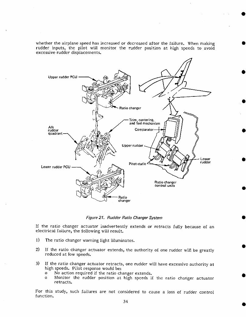
whether the airplane speed has increased or decreased after the failure. When making •rudder inputs, the pilot will monitor the rudder position at high speeds to avoidexcessive rudder displacements.
Figure 21. Rudder Ratio ChangerSystem •
If the ratio changer actuator inadvertently extends or retracts fully because of anelectrical failure, the following will result.
1) The ratio changer warning light illuminates.
2) If the ratio changer actuator extends, the authority of one rudder will be greatlyreduced at low speeds.
3) If the ratio changer actuator retracts, one rudder will have excessive authority athigh speeds. Pilot response would be:
o No action required if the ratio changer extends. •o Monitor the rudder position at high speeds i£ the ratio changer actuator
retracts.
For this study, such failures are not considered to cause a loss of rudder controlfunction.
34 •
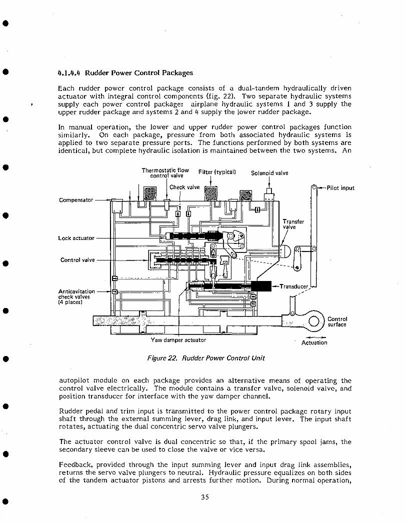
• #.l.¢.t_ Rudder Power Control Packages
Each rudder power control package consists of a dual-tandem hydraulically drivenactuator with integral control components (fig. 22). Two separate hydraulic systems
• supply each power control package: airplane hydraulic systems 1 and 3 supply theupper rudder package and systems 2 and € supply the lower rudder package.
In manual operation, the lower and upper rudder power control packages functionsimilarly. On each package, pressure from both associated hydraulic systems isapplied to two separate pressure ports. The functions performed by both systems areidentical, but complete hydraulic isolation is maintained between the two systems. An
• Thermostaticflow Filter(typical) Solenoidvalvecontrol valve
Checkvalve ---Pilot input
Compensator
Transfervalve
Lockactuator-- ]
• Control _']
Anticavitation
checkvalves(4 places)
Controlsurface
Yawdamperactuator Actuation
• Figure 22. Rudder Power Control Unit
autopilot module on each package provides an alternative means of operating thecontrol valve electrically. The module contains a transfer valve_ solenoid valve_ andposition transducer for interface with the yaw damper channel.
Rudder pedal and trim input is transmitted to the power control package rotary inputshaft through the external summing lever, drag link, and input lever. The input shaftrotates, actuating the dual concentric servo valve plungers.
The actuator control valve is dual concentric so that, if the primary spool jams, the
O secondary sleeve can be used to close the valve or vice versa.
Feedback, provided through the input summing lever and input drag link assemblies,returns the servo valve plungers to neutral. Hydraulic pressure equalizes on both sidesof the tandem actuator pistons and arrests further motion. During normal operation,
• 35
the internal linkage pivot point is maintained by pivot lock pistons exerting force •against a locking cam. If the servo valve of one power control package becomesjammed, the internal linkage will rotate the locking cam, thus allowing input to theother rudder powe r contro! package.
Rudder control functional and reliability block diagrams are shown in Figures23 and 24. •
It__ / I Hydraulic •
Electrical Isys2,4 I"7supply
II
Pitot- Ratio ! Ratio :_l Upperrudder ]static control changerunit
pedalsAftquadrant
Left _--_ Forward I ]
pedals quadrant Position •
Feel, ] indicating--_-- trim, and
centering
Trim _ m-_ Trim [knob actuator I •
1
Pit°t" I _ Rati° F Rati°
static--C°ntr°l unit I changert I_F L°werrudder 1I
I IElectrical Hydraulicsupply sys1,3
Electrical
Hydraulic-- _ Mechanical •
Pneumatic
Figure 23. Rudder Control Functional Block Diagram
36
• I !1Rudder Rudderpedal pedal
I II
• quadrant knob
I I
I Ca_'e I I• I I
quadrant actuator
I 1I
• I Iand ] / and Icentering I |centering
I I
• I I I
I Linkage 1 Linkage
I I• I _ I I
IO°oer] iO00°r [_°w°rI ['°w°r1actuator actuator actuator actuator
T T T TI1 I
Figure 24. Rudder Control Rel[abU/ty Block Diagram
• 37

//-.1.5 Speed Brakes •
The speed brake control system increases drag and reduces lift both in flight and onthe'ground. The system consists of 12 spoiler panels (numbered I through 12), a powercontrol package for each spoiler, speed brake control lever, drum mechanism_sequence mechanism_ ground spoiler control valv% and cables and pulleys to operatethe system. The five outermost spoilers on each wing are flight spoilers and the two •remaining spoilers (6 and 7) are ground spoilers.
The speed brake control lever located on the left side of the pilot control stand (fig.25) controls the system. The flight spoilers use hydraulic systems 27 3, and 4 while theground spoilers use hydraulic system 4. The fully raised position is 45 deg for spoilers1 through 4 and 9 through 12; it is 20 deg for spoilers 5 through 8. •
_ tT-Flight _-"\ spoilers
__ 9, 10 _ Flight
__.__j -. - spoilers, ,r._ouna8, 5_l_-_'_ spoilers
,f Spoiler 7, 6
" differential
mechanism
Flight
Autospeed--_brake 3, 4actuator
Speedbrakehandle PushrodQuadra
Control
stand -\Groundspoilercontrol Ratio
Speedbrake valve changersequencemechanism
Omechanism
Inflightlocksolenoid
Figure 25. SpeedBrake System
When using spoilers as speed brakes in flight, spoilers 3 through l0 are used. When thespeed brake control lever is moved to the FLIGHT stop, these spoilers are moved fromfaired to full travel. A solenoid-operated stop at the speed brake crank under thecabin Iloor arrests the speed brake control lever at the FLIGHT DETENT positionduring Ilight.
$.1.5.1 Speed Brake Control Lever •
The speed brake control lever, located on the lelt side ol the pilot control stand, iscoupled by linkage to the speed brake drum mechanism and by cable to the speed brakesequence mechanism.
38 •

• 4.1.5.2 Speed Brake Drum Mechanism
The speed brake drum mechanism consists of a cable quadrant and an irreversiblemechanism. The mechanism permits the main shaft to rotate in response to inputsfrom the speed brake control lever. It prevents the main shaft from rotating inresponse to the torque applied at the cable drum side. A cam is provided on the drum
• with a detent for the ARMED position. A spring-loaded roller arm follows the camand provides speed-brake-control-lever feel at this point.
_.1.5.3 Speed Brake Sequence Mechanism
The speed brake sequence mechanism receives the cable quadrant input from the speed
• brake control lever and programs an output to operate the flight and ground spoilers.The mechanism consists of a cable pulley, two input cranks connecting control rods tothe spoiler control differential mechanisms, a crank connecting a control rod to thespoiler control valve, and a housing assembly. The housing assembly contains amechanism that programs the positioning of the spoilers as speed brakes when thespeed brake lever is placed in the UP position. The speed brake mechanism is locatedin the right wing-gear wheel well.OTwo other output lever arms provide input to the spoiler control differentialmechanisms to operate the flight spoilers as speed brakes. The output from thesequence mechanism results in an output to the differential mechanism to activateflight spoilers 3, 4, 5, g, 9, and l0 for speed brake use in flight.
• The reliability block diagram for the speed brakes is shown in figure 26 and thefunctional block diagram is shown in figure 27.
q Spoiler . Iactuators I_--
• 3,1oI
q Spoiler N Cabe L--_SPtuilatrrsil Hydraulicl
leverbrake[-_1I Cable I1_11anismmech"-- actuatOrSs,_8]1' Isupply4 I
IHydraulic
Isupply2
[ Gr°und _Sp°iler I
spoiler actuatorsvalve 6,7
Figure 26. Speed Brake Reliability Block Diagram
• 39

•
•
•
•
•
•
•
•
•
•
Hydraulicsys 2
Position ,- Spoiler r-indicating 12
I
,SSpoiler f-- -mixer
iPosition I Spoilerindicating r-
4
~
L
SpoilerI mixer
I~
Figure 27. Speed Brake Functional Block Diagram
~l
I { s~~" '-- -I !I II II sp~ger f- --, I
I !Js::L 1'-- ~;";'UH'rt~ -~ 1-------1
Il'~lilI I I
II ri. Spo~ler ~~ II I
Ground H HISequence 1--1-_ I --- H d rI-- mechanism I-- fo -- spoiler y rau IC
valve L@ I sys 4
II ~------J Spoi Ier J I L........-..-.------J
I 6 I I III I
J III I
_UI II I
-,1t-I-
I~I
LI L!:J_J I--4 ILG:}__J
Spoiler panels 1,2, 11, 12not used in flight asspeed brakes
Speedbrakelever
ElectricalMechanical --- -Hydraulic - - --
40 •
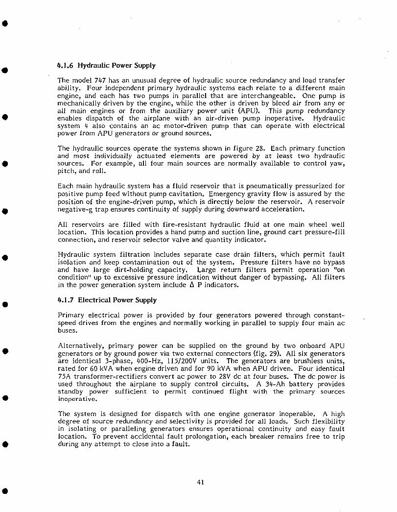
t#.l.6 Hydraulic Power SupplygThe model 7#7 has an unusual degree of hydraulic source redundancy and load transferability. Four independent primary hydraulic systems each relate to a different mainengine, and each has two pumps in parallel that are interchangeable. One pump ismechanically driven by the engine, while the other is driven by bleed air from any orall main engines or from the auxiliary power unit (APU). This pump redundancy
• enables dispatch of the airplane with an air-driven pump inoperative. Hydraulicsystem tt also contains an ac motor-driven pump that can operate with electricalpower from APU generators or ground sources.
The hydraulic sources operate the systems shown in figure 28. Each primary functionand most individually actuated elements are powered by at least two hydraulic
• sources. For example, all four main sources are normally available to control yaw,pitch, and roll.
Each main hydraulic system has a fluid reservoir that is pneumatically pressurized forpositive pump feed without pump cavitation. Emergency gravity flow is assured by theposition of the engine-driven pump, which is directly below the reservoir. A reservoir
• negative-g trap ensures continuity of supply during downward acceleration.
All reservoirs are filled with fire-resistant hydraulic fluid at one main wheel welllocation. This location provides a hand pump and suction line, ground cart pressure-fillconnection, and reservoir selector valve and quantity indicator.
• Hydraulic system filtration includes separate case drain filters, which permit faultisolation and keep contamination out of the system. Pressure filters have no bypassand have large dirt-holding capacity. Large return filters permit operation "oncondition" up to excessive pressure indication without danger of bypassing. All filtersin the power generation system include A p indicators.
tt.l.7 Electrical Power Supply
Primary electrical power is provided by four generators powered through constant-speed drives from the engines and normally working in parallel to supply four main acbuses.
Alternatively, primary power can be supplied on the ground by two onboard APU• generators or by ground power via two external connectors (fig. 29). All six generators
are identical 3-phase, #00-Hz, I IS/200V units. The generators are brushless units,rated for 60 kVA when engine driven and for 90kVA when APU driven. Four identical75A transformer-rectifiers convert ac power to 28V dc at four buses. The dc power isused throughout the airplane to supply control circuits. A 3#-Ah battery providesstandby power sufficient to permit continued flight with the primary sources
• inoperative.
The system is designed for dispatch with one engine generator inoperable. A highdegree of source redundancy and selectivity is provided for all loads. Such flexibilityin isolating or paralleling generators ensures operational continuity and easy faultlocation. To prevent accidental fault prolongation, each breaker remains free to trip
• during any attempt to close into a fault.
41

Engine 4bleed air
System 4
: : II.~i:I~n:JJI:i~I3I:J:Dcir-----------·---~----' l...--1;""_~ J, r----------~----------:, ~i9ht m Ratio changer,I CCA "t' actuator I
I :: ---;--- -,----4-------,+--..!..,----'-;--'- --'-:r--' I1:::--:-1:':'---':';-:±:=-T--~ - ---;--r - ----1- -;--~
I : I' . I Is;"., II po, ., I SP~;I.' I'~ SPOi'.,: ISp~i1., I.1 : I 7 I 8 9 ILiI:J 11 : 12
1- - -t-, -- - -4- - '- J Lf=;:rr=::r: ~ _[""""J.. Outboard TEI t......:r flap drive, I, LEGEND (CONTII
: ~ Hydraulic motor, ,: '---B----------------,
,- - ~ -,a~,:,--~~ t: ::e_-: -;':b~,~- - ---~ -- - - -: I~mHvd'aulic brake
1l modu e R module , I I I e Electric motor-operated
--..-----l r----------.-.J I I I~ valvelnormallyopen)
M Stabilizer M -- --- ..--::-~ Elevator feel J- --7 - - - -:- --- -, E3 Flap control valvepitch trim computer __ -+ .J __ ., I Igearbox B J: I
p:J::::::l Dual tandem actuatorL ~-------_,: I
r-------:: :.:::..:..-_- -r __::.I---=:'-~ :--.-.::.:.::r~ _---J• I I I
Ii==+c=;:::::r'
Engine 2bleed air
Air-driven pump
Engine-driven pump
AC motor-driven pump
System reservoir
Reservoir pressurizationsystem
Pneumatic drivehydraulic pump
,""t'""----r--f -- f--1- --- --1- - -
I~PO:,., III ;p;"., I I~PO,'" I
Engine 1bleed air
System 1
~
~IAESll!TIJfPDl~
8e
'-=='-oL"E;!GENDHyd power sys \Hyd power sys 2Hyd power sys 3Hyd power sys 4Fluid supplyPneumatic pressure
Figure 28. Flight Control Hydraulic System
• • • • • • •• • • • •
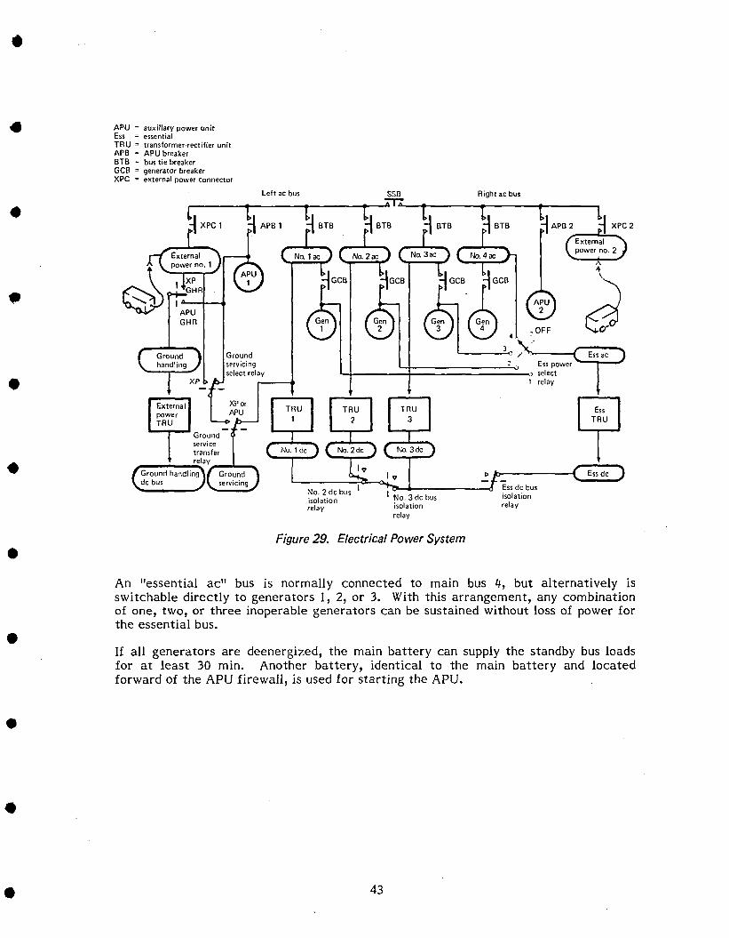
•
Ess de
t~ APB2
--"'-=--.
fiJT
Right ac bus
L+- ~+:=======~::..._. Ess power ----1 select1 relay
t> 1:>-------(
'-:~=T~-t-J_---..:J ---Ess de busI No_ 3 de bus isolation
isolation relayrelay
t~ APBl
XPorAPU
Groundservicingselect relay
I "'--i-'"APUGHR
ExternalpowerTRU
Left ac bus
APU = auxiliary power unitEss = essentialTRU = transformer-rectifier unitAPB = APU breakerBTB = bus tie breakerGCB = generator breakerXPC = external power connector
•
•
•
•
•Figure 29. Electrical Power System
•
An "essential ac" bus is normally connected to main bus 4, but alternatively isswitchable directly to generators 1, 2, or 3. With this arrangement, any combinationof one, two, or three inoperable generators can be sustained without loss of power forthe essential bus.
If all generators are deenergized, the main battery can supply the standby bus loadsfor at least 30 min. Another battery, identical to the main battery and locatedforward of the APU firewall, is used for starting the APU.
•
•
• 43
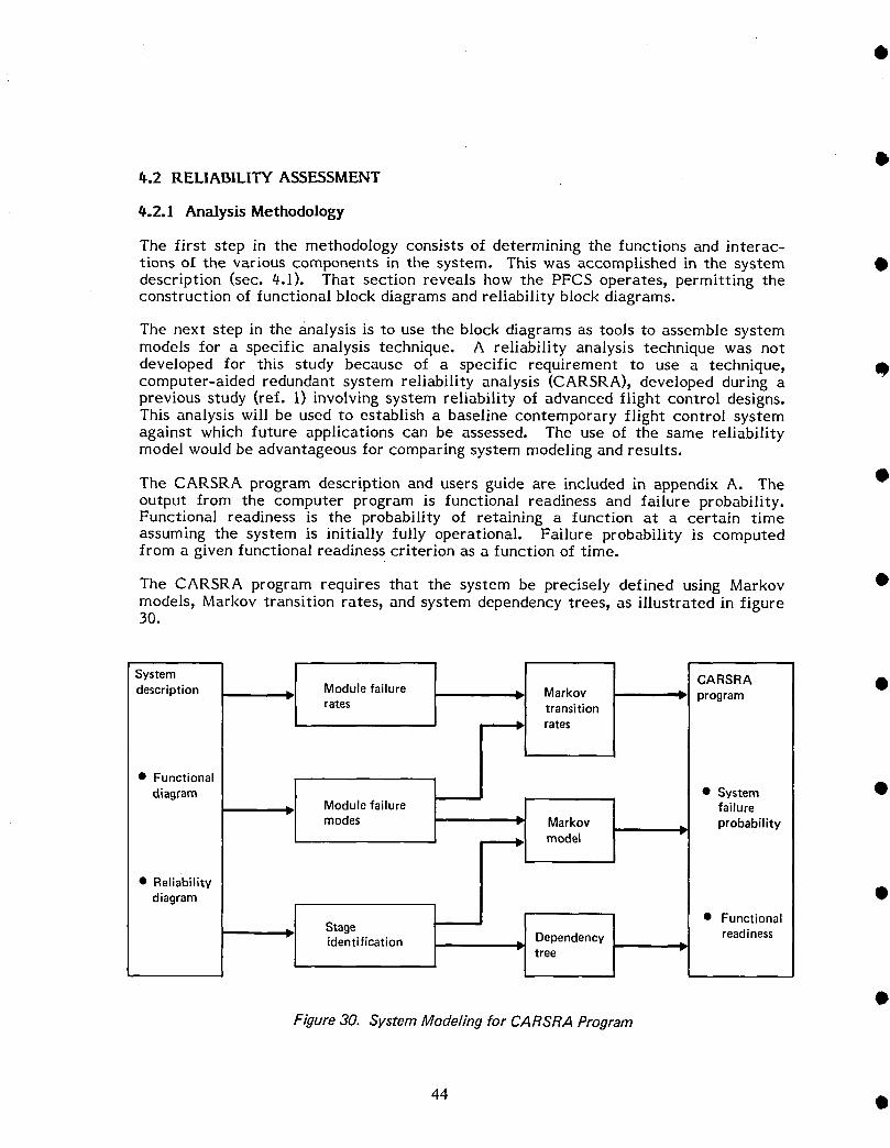
O_.2 RELIABILITY ASSESSMENT
#.2.1 Analysis Methodology
The first step in the methodology consists of determining the functions and interac-tions of the various components in the system. This was accomplished in the system •description (sec. 4.1). That section reveals how the PFCS operates9 permitting theconstruction of functional block diagrams and reliability block diagrams.
The next step in the analysis is to use the block diagrams as tools to assemble systemmodels for a specific analysis technique. A reliability analysis technique was not
developed for this study because of a specific requirement to use a technique_ Qcomputer-aided redundant system reliability analysis (CARSRA)9 developed during aprevious study (ref. 1) involving system reliability of advanced flight control designs.This analysis will be used to establish a baseline contemporary flight control systemagainst which future applications can be assessed. The use of the same reliabilitymodel would be advantageous for comparing system modeling and results.
The CARSRA program description and users guide are included in appendix A. The •output from the computer program is functional readiness and failure probability.Functional readiness is the probability of retaining a function at a certain timeassuming the system is initially fully operational. Failure probability is computedfrom a given functional readiness criterion as a function of time.
The CARSRA program requires that the system be precisely defined using Markov •models_ Markov transition rates9 and system dependency trees_ as illustrated in figure30.
Syteml I CARSRA.description _ Module failure Markov -_ programrates transition
rates
• Functional
diagram [ PI • System •
_. Module failure failuremodes Markov probability
diagram •
I • Functional
= Stage Dependency readinessidentification _" tree
Figure 30. System Modeling for CARSRA Program
44 •
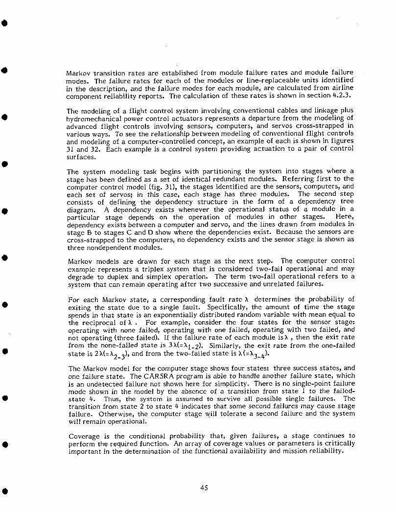
Markov transition rates are established from module failure rates and module failuremodes. The failure rates for each of the modules or line-replaceable units identified
in the description, and the failure modes for each module, are calculated from airlinecomponent reliability reports. The calculation of these rates is shown in section #.2.3.
The modeling of a flight control system involving conventional cables and linkage p!us• hydromechanical power control actuators represents a departure from the modeling of
advanced flight controls involving sensors, computers, and servos cross-strapped invarious ways. To see the relationship between modeling of conventional flight controlsand modeling of a computer-controlled concept, an example of each is shown in figures31 and 32. Each example is a control system providing actuation to a pair of controlsurfaces.
The system modeling task begins with partitioning the system into stages where astage has been defined as a set of identical redundant modules. Referring first to thecomputer control model (fig. 31), the stages identified are the sensors, computers, andeach set of servos; in this case, each stage has three modules. The second stepconsists of defining the dependency structure in the form of a dependency tree
O diagram. A dependency exists whenever the operational status of a module in aparticular stage depends on the operation of modules in other stages. Here,dependency exists between a computer and servo, and the lines drawn from modules instage B to stages C and D show where the dependencies exist. Because the sensors arecross-strapped to the computers, no dependency exists and the sensor stage is shown asthree nondependent modules.
• Markov models are drawn for each stage as the next step. The computer controlexample represents a triplex system that is considered two-fail operational and maydegrade to duplex and simplex operation. The term two-fail operational refers to asystem that can remain operating after two successive and unrelated failures.
For each Markov state, a corresponding fault rate _, determines the probability of• exiting the state due to a single fault. Specifically, the amount of time the stage
spends in that state is an exponentially distributed random variable with mean equal tothe reciprocal of X. For example, consider the four states for the sensor stage=operating with none failed, operating with one failed, operating with two failed, andnot operating (three failed). If the failure rate of each module isX, then the exit ratefrom the none-failed state is 3A(=XI_2). Similarly, the exit rate from the one-failed
• state is 2X(=X2_3), and from the two-failed state is X(=X3_#).
The Markov model for the computer stage shows four states: three success states, andone failure state. The CARSRA program is able to handle another failure state, whichis an undetected failure not shown here for simplicity. There is no single-point failuremode shown in the model by the absence of a transition from state I to the failed-
• state #. Thus, the system is assumed to survive all possible single failures. Thetransition from state 2 to state # indicates that some second failures may cause stagefailure. Otherwise, the computer stage will tolerate a second failure and the systemwill remain operational.
Coverage is the conditional probability that, given failures, a stage continues to• perform the required function. An array of coverage values or parameters is critically
important in the determination of the functional availability and mission reliability.
• 45
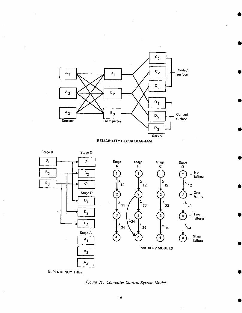
I A3 B3 _ Control
Sensor Computer _ D3 _-J surface •Servo
RELIABILITY BLOCKDIAGRAM
StageB StageC
I IL B1 I "1= C1 StageA StageB StageC StageD
92 I =1 C2J "1 ] ( ) (_) (_ _) Nofailure
B3 i ! C3 I 12 k k kI i _'1 I 12 12 12 •
( 5 d)Stage D _ _ One' failure
23 23 23 23
D2 , • _ Two •• ' failures
_'l D3 ! ;34 X34 X34 _34
StageA ' ._ _ (_• StageA1 • - failure
I A2 I MARKOV MODELS
DEPENDENCY TREE •
Figure 31. Computer Control System Model
46 •

_ Controlsurfacei
Controlsurface0
Cableinput Power Actuators
sources
• RELIABILITY BLOCKDIAGRAM
StageB StageC
Stage Stage Stage StageA B C D
_ _ (___ NofailureI J I I )` )`
12 13 )`_'12 )'12 12StageD
• _ _ )One' failure
)` 24 )`34 )` X X23 23 23
StageA _ _ _ _ _ _-- St_gu;e
• _'_ )`34
• x45DEPENDENCY TREE
_ _--Stagefailure
• MARKOVMODELS
Figure 32. Mechanical Control System Model
4?
In the computer stage, a second failure from state 2 can be tolerated only if it is •detected and isolated to achieve successful redundancy degradation to state 3 orsimplex operation. The percentage of second failures that are successfully detectedand isolated is the second-failure coverage.
The final step consists of establishing the success criteria for system operation. Inthis case, it is assumed that control is acceptable if only one control surface is •operating. CARSRA will model this situation by accepting a success event tabulationcovering all nondependency stage combinations equivalent to system success.
The modeling steps for the mechanical control system example shown in figure 32 areidentical to the computer control system example. Stage identification includes onestage for the four independent power sources, one stage for each actuation package •serving the respective control surfaces, and one stage for the control cable inputs.The control cable input stage contains modules having different failure rates.CARSRA has the capability to handle this situation although the airborne advancedreconfigurable computer system (ARCS) concept was confined to stages havingidentical modules. Dependency exists between power source modules and actuatormodules; the dependency tree shows this. The cable inputs form a nondependent stagebecause the input to a control surface actuation channel can come Irom either input •module. The Markov model shows five failure states for the power source stage. Ifsuccess criteria establish that control is acceptable with only one control surfaceoperating and that the actuator stages are each one-fail operational (able to operateafter one failure), then the power source stage can suffer three module failures; i.e.,fail to state 4 belore stage failure to state 5. The identification of coverage
parameters is not significant here because the power sources are independent of eachother. A first, second, or third power source failure need not be detected and isolatedbecause there is no need to identify and vote out the failed source; each Iailure ispassive and there is no transition to state 5 Irom states 1, 2, or 3. The Markov modelfor the cable input stage shows four states, but only one Iailure state exists beforestage failure. It is assumed for this example that the failure rate or transition rate for •each input A1 and A2 are different. This can be the case if one input is by main pilotcontrol and the other input is by a trim cable system. Failure order then dictates thisform of the Markov model. If AI fails first, followed by A2, transition is from state 1to state 2 Ior A1 failed and transition from state 2 to state # when A2 fails.Transition from stgte I to state 3 to state g occurs when A2 fails before A1.
In general, a system can be modeled in more than one way by grouping differentmodules in a stage to suit a particular success configuration. Usually, it is desirable tocombine as many modules as possible in a stage, if the success configurations can bemaintained and the Markov models are not too large. CARSRA is limited to nineIailed states in the Markov model and 20 different success configurations.
QA feature of CARSRA is the ability to assess functional readiness as well as systemfailure probability. The concept of functional readiness is useful for a flightcontaining a critical subtask that will either be performed or not depending on theoperational redundancy level at the time of demand. An example is the category IIautoland function of the automatic flight control system. For this example, afunctional readiness criterion is established that specifies what elements of the flightcontrol system can fail without losing the autoland Iunction. The system functional •readiness for selected module Iailure patterns is computed by CARSRA and representsthe probability that category II autoland will be available at the end of a flight.
48

Speed brake deployment is a subtask that may be required at a particular phase of• flight for the primary flight control system (PFCS). Speed brakes are often used to
reduce airspeed when a pilot must make a rapid descent as part of an air trafficcontrol maneuver. The functional readiness of the speed brake system will be assessedat the descent phase of the flight.
4.2.2 Control Function Definition
In the model 747, all flight control surfaces are power actuated. High multiplicity ofpower sources, command paths, power actuators, and control surfaces has eliminatedmanual reversion. There are 23 structurally independent, movable control surfaces(not including the high-lift devices): four ailerons, four elevators, two rudders, ahorizontal stabilizer, and 12 spoilers.
• #.2.2.1 Control Inputs
The primary control cabin controls for surface movement are two conventional controlcolumns, two control wheels, and two sets of rudder pedals. Control surface actuationcan also be accomplished by the trim system, which is available in all three controlaxes. Another source that maintains control in flight is the input from the autopilot
• and yaw damper system. However, for this study, the analysis includes only themechanical controls available to the pilot and copilot.
_.2.2.2 Actuation and Power Sources
Each aileron, elevator (except the outboard elevator), and rudder is driven by two• independent hydraulic sources. The identity of these sources varies from surface to
surface and is available from four different pairings of the airplane's four hydraulicsystems. As a result of these assigned energy sources, airplane control around each ofthe three axes (roll, pitch, and yaw) is powered by all four hydraulic systems. Innormal operation, hydraulic systems 2 and 3 have no assignment other than flightcontrol. They are, in that sense, the basic flight control energy supplies. However,
• even if both of these primary systems were to fail, the source redundancy is such thatthe aileron, elevator, and rudder sections could still be moved.
The degree of redundancy in the 70,7 PFCS establishes that airplane control can bemaintained with loss of some input control, power sources, and actuation to controlsurfaces. For the reliability analysis, a failure definition is established governing a
• combination of control surfaces that are required to maintain the control function.These control functions are defined in table l, including the required inputs, powersources, and surfaces. For simplicity, the terms I/3 I/B and I/20/B used in the tablerefer to one-third of all left and right inboard spoiler surfaces, and one-half of all leftand right outboard spoiler surfaces. Figure 12 shows the location of the inboard andoutboard spoilers, and the reliability diagram in figure 18 shows the pairing for leftand right spoilers.IIThe definitions (table l) for each control function do not identify absolute controlminimums. It could be, for example, that only one inboard elevator is operating in theelevator control system. Whether adequate control can be maintained will depend onfactors such as availability of other flight controls, the center-of-gravity position, andengine-out possibilities. Because the reliability analysis is confined to each separate
• control function, these definitions are considered appropriate for each controlfunction. The reliability results will, therefore, show the probability of not maintain-ing a control function and not necessarily the probability of losing control in thatparticular flight axis.
• 49
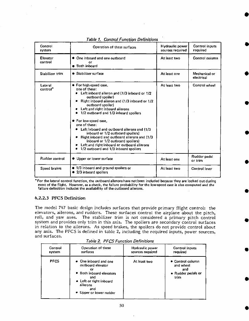
Table. 1., Control Function Definitions
Control Operationof thesesurfaces Hydraulicpower Controlinputs •system sourcesrequired required
Elevator • Oneinboardandoneoutboard At leasttwo Controlcolumncontrol or
• Both inboard
Stabilizertrim • Stabilizersurface At leastone Mechanicalor Oelectrical
Lateral • For high-speedcase, At leasttwo Control wheelcontrol* oneof these:
• Left inboardaileronand(1/3 inboardor 1/2outboardspoiler)
• Right inboardaileronand(1/3 inboardor 1/2outboardspoiler) •
• Left andright inboardailerons• 1/2 outboardand1/3 inboardspoilers
• For low-speedcase,oneof these:• Left inboardandoutboardaileronsand (1/3
inboardor 1/2 outboardspoilers) •• Rightinboardandoutboardaileronsand (1/3
inboardor 1/2 outboardspoilers)• Left andrightinboardoroutboardailerons• 1/2 outboardand 1/3 inboardspoilers
Rudderpedal
Ruddercontrol • Upperor lowersurface At leastone or trim
Speedbrakes • 1/3 inboardandgroundspoilersor At leasttwo Control lever• 2/3 inboardspoilers
* For the lateralcontrolfunction,the outboardaileronshavenotbeenincludedbecausetheyare lockedout duringmostof the flight. However,asa check,the failureprobabilityfor the low-speedcaseisalsocomputedandthe
failuredefinitionincludesthe availabilityof the outboardailerons. •
$.2.2.3 PFCS Definition
The model 747 basic design includes surfaces that provide primary flight control: theelevators, ailerons, and rudders. These surfaces control the airplane about the pitch_roll, and yaw axes. The stabilizer trim is not considered a primary pitch controlsystem and provides only trim in this axis. The spoilers are secondary control surfaces •in relation to the ailerons. As speed brakes, the spoilers do not provide control aboutany axis. The PFCS is defined in table 2_ including the required inputs, power sources,and surfaces.
Table 2. PFCS Function Definitions
Control Operationof these Hydraulicpower Controlinputs •system surfaces sourcesrequired required
PFCS • Oneinboardandone At leasttwo • Controlcolumnoutboardelevator andwheel
or and• Both inboardelevators • Rudderpedalsor
and trim •• Left or right inboardailerons
and• Upperor lowerrudder
50 •

• 4.2.3 Component Reliability
The system reliability evaluation requires that failure transitions be assessed in eachof the stage modules that make up the system model. Transition rates are determinedfrom module failure rates, failure mode, and system operating characteristics. Forthis study, a module is identified as a component or series of components that perform
O a function.
Component failure rates and failure modes are available primarily from airline recordsat the line-replaceable unit (LRU) level. In some cases, an LRU may include anassembly of components. In such cases it will be necessary to refer to airline overhaulshop records to identify specific components.
• 4.2.3.1 Airline Records
The method used to obtain or derive module failure rates is to research airline
technical reports. The airlines produce reports to show trends in mechanical operatingperformance and also to keep track of material usage, i.e., the frequency ofcomponent replacements. One such report is the unscheduled component removal
• report. The unscheduled removal rate is obtained from this report for most itemsidentified in the functional block diagram in the system descriptions, section 4.1.
The objective is to derive the functional failure rate for each component, which thenforms the basis of the transition rate in the reliability model. Functional failuresinclude only modes of failure that are considered to result in a loss of function. The
• flow diagram in figure 33 indicates what steps are necessary to determine thefunctional failure rate.
Information provided in the component removal reports shows the number of unsched-uled removals in a given time period plus the removal rate as a function of the flight-hours flown for that period. Some components may have been removed during
• troubleshooting, not because they failed. For this study, only justified removals(removals caused by failure) are of interest. In many cases, the airline report willindicate the percentage of justified removals.
The failure rate is the product of the removal rate and the proportion of justifiedremovals. However, more information is required about the justified removal before a
• functional failure rate can be derived. The failure modes must be identified andcategorized into functional failures and nonfunctional failures. This information isavailable in airline shop records. The functional failure rate is then the product of thefailure rate and the proportion of functional failures.
/_.2.3.2 Component Removal Rates
D The reliability of the mechanical elements in the flight control system is generallymuch higher than the flight control electronics. Component removal data must,therefore, be collected over a long time span. Appendix B includes removals, hours,and removal rates for the major flight control LRU's. The data base is an assembly ofseveral separate airline reports that goes back to the start of model 747 service in1970 and extends through 1976. Removal rates used in this study are the cumulative
• rates. Where the trend shows a marked improvement for any component, the averageof the past 4 years is used. For most components, a justified removal percentage isalso shown. The justified percentage is not available for components with very low
51

?
removal rates; therefore, all removals are considered justified_ unless other available •reports show otherwise. Removal rates for each control system and the percentage o£justified removals are summarized in table 3.
Unscheduled
componentremovals
it t °
On, Iremovals removals modes
I °1 1
I Functional tT _ Failures,
failures othercauses •
Percentageof Percentageofjustified functional
removals failures •
I I
Functionalfailure •rate*
1Markovtransition _ CARSRA •rate program
* Functional failure rate= unscheduledremovalrate x percentageof justifiedremovals/100x percentageof functional failures/100 •
Figure 33. Functional Failure Rate Determination
52

0 Table 3. Summary of Airline Component Removal Rates
Removals per Justified removalsComponent 106 unit hours (percent)
ElevatorControl column 0
ID Aft quadrant 0Feel unit 1.6 100"Feel actuator 16.8 I00"Feel computer 62.7 84Inboard power control unit 62.8 93Outboard power control unit 17.0 100
Stabilizer trim• Hydraulic motor 20.4 100"
Gear drive 0.6 100"Hydraulic brake 1.7 100"Shutoff valve 6.5 100"Control module 28.7 100
Lateral control
• Control wheel 0Trim and feel mechanism 0.9 100"Trim actuator 13.0 100"Central control actuator 30.0 61Aileron programmer 0.4 100"Spoiler differential (mixer) 0Load limiter 0Inboard aileron power control unit 37.1 100
• Outboard aileron power control unit 22.3 100Outboard aileron lockout actuator 8.0 100"Outboard aileron lockout gearbox 1.7 100"Flight control shutoff valve 6.6 100Inboard spoiler power control unit 15.3 80Outboard spoiler power control unit 14.0 92
• RudderFeel trim and centering mechanism 0Aft quadrant 1.7 100"Ratio control unit 161.3 52
Ratio changer actuator 111.9 44Ratio changer comparator 186.5 100Power control unit 67.7 94
• Trim actuator 3.6 100"
Speed brakesControl lever 3.3 100"Sequence mechanism 1.2 100"Ground spoiler control valve 2.4 100"Ground spoiler actuator 9.7 100"
• * The removals for these components was assumed 100% justified.
_.2.3.3 Functional Failure Rate Analysis
To develop functional failure rates from failure modes and component failure rates,the overhaul workshop findings and maintenance and flight inspection frequencies must
• be used with prediction analyses.
Mechanical Elements-These elements of the system seldom Sail. Functional failurerates are determined in the following two ways. In cases where airline reports
53
indicate zero removals for mechanical elements, yet preflight checks detect a failure, •a functional failure rate of zero is used. In cases where an airline does not report theremoval record for mechanical elements, and a review of other records does not showany removals, yet there are regular inspection intervals, a functional failure of 1/3 isused. This figure is obtained from the reference 2 reliability paper, which provides anestimate for the exponential failure rate from data with no failure events. This 1/3failure can be applied over the accumulated 747 flight time. •
Mechanical control failures = 1/3
747 flight-hours to December 1977 = 5,300,000 hrFunctional failure rate = 0.06 failure/106 hr
This failure rate is conservative; each mechanical item is exposed to regular •maintenance inspections and all reported removals were considered justified.
Cables-Control cables are used for the main control paths from the pilot controlcolumn and rudder pedals; for trim in roll, pitch, and yaw; and for interconnecting withmultiple surface actuation as in spoilers and outboard elevators. The functional
failure modes for cables and associated pulleys are cable breakage, pulley breakage, •cable-pulley jamming from foreign objects, and cable jamming from ice. Experiencewith cables on the 747 has been excellent. 3ust one incident has been reported to theFAA. This was ice accumulation on an aileron cable, which prevented surfaceactuation. Actuation was possible later in the flight.
A functional failure rate of 0.06 failure per l06 hr is used for each cable-pulleycontrol run as a conservative estimate. This is the same rate as used for mechanical •elements with zero failure events.
Hydraulic Modules-Removal rates for hydraulic equipment are higher than those formechanical items; these rates can be determined from airline shop records and used toassess functional failures. Appendix C is a record of power control unit (PCU) shopfindings covering a group of five airlines over a b-year period. Most PCU removals are •for internal leakage problems where hydraulic fluid pressure, temperature, moisturecontent, and other contaminants have caused the moving parts to erode internally.Functional failures will occur in 5% of the PCU removals explained as follows.Normally, an actuator will continue to function adequately with a certain degree ofinternal leakage and usually the unit is replaced before excessive leakage develops. Aspart of scheduled maintenance, an operator will conduct a leakage check on each Qhydraulic system. If the internal leakage rate exceeds certain levels, the high-leakagecomponent or components must be replaced. When low hydraulic power is combinedwith the presence of a unit with high internal leakage, at a time of high powerdemand_ force may be insufficient to move a control surface the desired amount. Thisis considered a functional failure. For this analysis, the functional failure rate is 50%of every removal for internal leakage times an estimated probability of 10% of every IIflight that did not have sufficient power for adequate actuation.
Hydraulic Power-Hydraulic pressure for each of the four systems is supplied normallyby power from four engines through four engine-driven pumps. Power is also availablefrom the pneumatic source, engine bleed air, or APU to four air-driven pumps mounted
next to each engine-driven pump. Hydraulic pressure can be lost only when both power •sources are unavailable.
54

The distribution of pressure for each hydraulic system is not redundant. A linebreakage or component housing fracture will result in hydraulic fluid loss andsubsequent pressure loss even though the power source may still be available. This lossresults in no power to the actuators and prevents mechanical actuation. Withactuators that have dual cylinders served by two hydraulic systems, the fluid loss fromone system does not prevent mechanical actuation.@A hydraulic system failure rate used for this study is the hydraulic pressure loss rate.It can be calculated from the number of times fluid has been lost and the number ofhours flown for each system. Power source losses are small compared with fluidlosses.
• Hydraulic system losses for two model 747 operators are detailed in appendix D.Fractures of flight control power units that result in fluid losses are counted in thehydraulic system loss rate, but are not counted again as a power unit failure.
There were 39 system losses for the two operators between February 1975 and April19769 with an accumulated flight time of 2239857 hr. For each hydraulic system, the
• loss rate equalled 43.5/106 hr.
Although the individual loss rates will be different for each of the four systems, anaverage loss rate figure is used. This is done because the CARSRA program is set upmore efficiently to handle similar modules having identical failure rates.
_1! Electrical Power--The primary electrical power is provided by four generators poweredthrough constant-speed drives (CSD) from the engines and normally working in parallelto supply four main ac buses. The failure rate for each generator channel is the sumof the component failure rates, as listed in table t_.
Table 4. Electrical Power Corr _onent Failure Rates
• Component Failure per 106 hr
a.c.elements
Constant speeddrive 333.0
Generator 228.7
Constant speeddrive oil cooler 15.5
Frequency load controller 45.1Generator control unit 236.5
Engine (in-flight shutdowns) 84.8*
X=943.6
d.c. elements
Essential relay diode 2.4
O Transformer rectifier unit 10.2
Isolation relay 15.6
* 212.0 failures per 106 hourswith 60% restarts
The probability of losing essential ac bus power during a l-hr flight (t) equals the
• probability of losing all four generator channels.
= (1 - e- _t)4
= 0.79 x 10⁻¹²
• 55
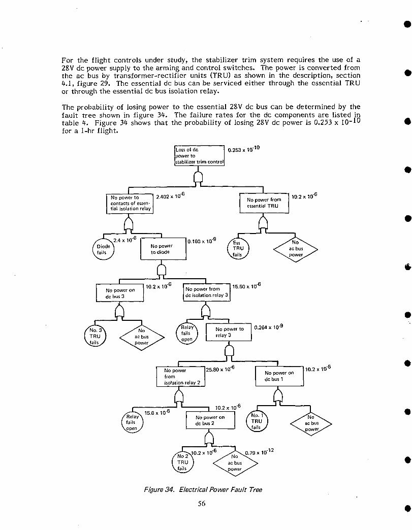
For the flight controls under study) the stabilizer trim system requires the use of a28V dc power supply to the arming and control switches. The power is converted fromthe ac bus by transformer-rectifier units (TRU) as shown in the description) section •4.1) figure 29. The essential dc bus can be serviced either through the essential TRUor through the essential dc bus isolation relay.
The probability of losing power to the essential 28V dc bus can be determined by thefault tree shown in figure 34. The failure rates for the dc components are listed intable 4. Figure 34 shows that the probability of losing 28V dc power is 0.253 x I0 -10 •for a l-hr flight.
Loss of dc I 0.253 x 10"10power tostabilizer trim contro$
I I
I N°p°wert° I 24°2x 1°6 l 1°2x 1°6contacts of essen- ] No power from
tial isolation relay I essentialTRU
•0,160 x 10.9
tN°d_°deer
I 10.2 x 10.6 I
Nopoweron [ I No power from [ 15"60 x I0"6dc bus 3 dc isolation relay 3
•wer to 0.264 x 10.9
I I •
10-0°n', ".2 10"12
Figure 34. Electrical Power Fault Tree
56 •

_.2.3.t_ Functional Failure Rates
This section describes the calculation of the functional failure rates of each of themodules used in the reliability analysis. The term "open/jam" is used for failure modesof mechanical components. "Open" refers to disconnection through loss of connections
D (e.g., pins) or breakage. "3am" refers to the component movement being obstructed byeither a foreign object or a bent component. The modules are grouped within theirrespective control function and are listed in the following order; elevator, stabilizertrim, lateral control (ailerons and spoilers)_ rudder_ and speed brakes. These modulesare summarized in table 5 and Jisted below.
• o ELEVATOR
Control columnRemoval rate = 0 removals/106 unit-hoursFunctional failure mode--open/jamFunctional failure rate = 0 failures/106 hr
BForward quadrant
No removal reported for this itemFunctional /allure mode--open/jamAssume 1/3 failure in 5_300,000 flight-hoursFunctional failure rate = 0.06 failure/106 hr
Aft quadrantRemoval rate = 0 removals/106 unit-hoursFunctional failure mode--open/jamFunctional failure rate = 0 failures/10 v hr
Rear linkage• This is a dual load path linkage
No removal reported for this itemFunctional failure mode-open/jamAssume 1/3 failure in 5,300,000 flight-hours for each load pathFunctional failure rate = 0.06 failure/106 hr
• Inboard elevator power control unit (PCU)Removal rate = 62.8 removals/106 unit-hoursPercent justified removals = 93%Functional failure mode-loss of function, high internal leakageFrom appendix C, workshop findings for PCU's :Functional fai!ures--high internal leakage = 67/12t_ x 5%
a --other = 0/12t_Functional failure rate = 1.6 failures!!06 hr
Outboard elevator power control unit (PCU)Removal rate = 17.0 removals/106 unit-hoursPercent justified removals = 100%
• Functional failure mode-loss of function, high internal leakageFrom appendix C, workshop findings for PCU's:Functional failures-high internal leakage = 21/36 x 5%
--other = 0/36Functional failure rate = 0.5 failure/106 hr
• 57
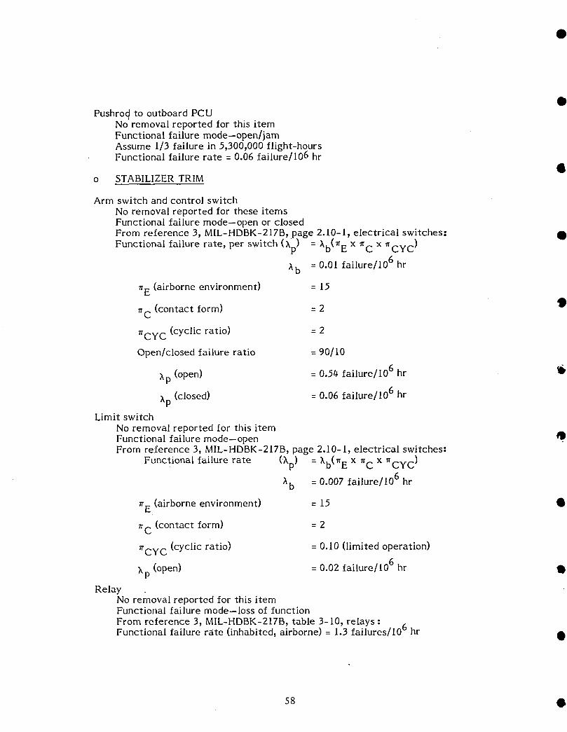
Pushrod to outboard PCUNo removal reported for this itemFunctional failure mode-open/jamAssume 1/3 failure in 5)3009000 flight-hoursFunctional failure rate = 0.06 failure/106 hr
o STABILIZER TRIM
Arm switch and control switchNo removal reported for these itemsFunctional failure mode--open or closedFrom reference 3, MIL-HDBK-217B, page 2.10-I, electrical switches: •
Functional failure rate, per switch (Xp) = Xb(_ E x _C x _CYC )
= 0.01 failure/106 hrAb
r E (airborne environment) = 15
_C (contact form) = 2
_CYC (cyclic ratio) = 2
Open/closed failure ratio = 90/I0
Xp (open) = 0.54 failure/106 hr II_
Xp (closed) = 0.06 failure/106 hrLimit switch
No removal reported for this itemFunctional failure mode--openFrom reference 3) MIL-HDBK-217B) page 2.10-1) electrical switches:
Functional failure rate (Xp) = Xb(_ E x _C x _CYC )
Xb = 0.007 failure/106 hr
r E (airborne environment) = 15 •
_C (contact form) = 2
_CYC (cyclic ratio) = 0.10 (limited operation)
X (open) = 0.02 failure/106 hr IIP
RelayNo removal reported for this itemFunctional failure mode--loss of function
From reference 37 MIL-HDBK=217B7 table 3= 107 relays : 6Functional failure rate (inhabited) airborne) = 1.3 failures/10 hr •
s8 •
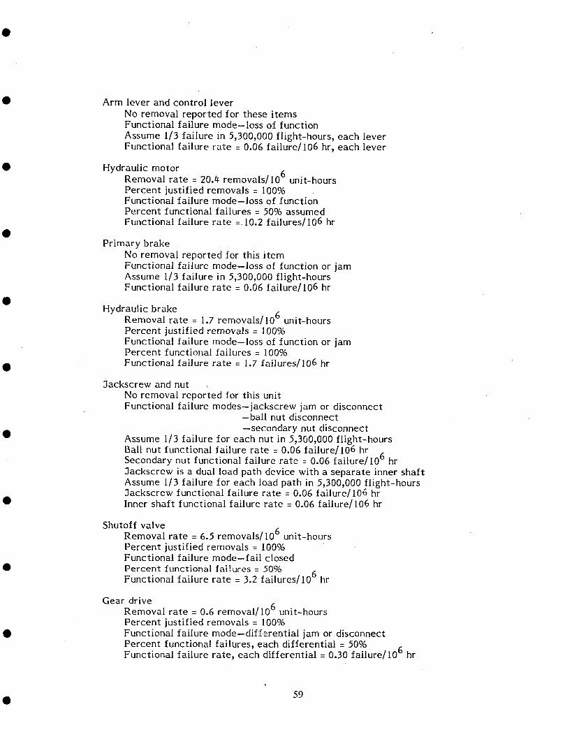
• Arm lever and control lever
No removal reported for these itemsFunctional failure mode-loss of function
Assume 1/3 failure in 5,3009000 flight-hours, each leverFunctional failure rate = 0.06 failure/10B hr, each lever
• Hydraulic motorRemoval rate = 20./_ removals/10 B unit-hoursPercent justified removals = 10096Functional failure mode-loss of functionPercent functional failures = 5096 assumedFunctional failure rate = 10.2 failures/10B hr
Primary brakeNo removal reported for this itemFunctional failure mode--loss of function or jamAssume 1/3 failure in 5,300,000 flight-hoursFunctional failure rate = 0.06 failure/106 hr
Hydraulic brakeRemoval rate = 1.7 removals/106 unit-hoursPercent justified removals = 100%Functional failure mode-loss of function or jamPercent functional failures = 100%
• Functional failure rate = 1.7 failures/106 hr
3ackscrew and nutNo removal reported for this unitFunctional failure modes--jackscrew jam or disconnect
-ball nut disconnect
--secondary nut disconnect• Assume I/3 failure for each nut in 5,300,000flight-hours
Ball nut functional failure rate = 0.06 failure/106 hr .Secondary nut functional failure rate : 0.06 failure/10 b hr3ackscrew is a dual load path device with a separate inner shaftAssume I/3 failure for each load path in 5,300,000 flight-hours3ackscrew functional failure rate = 0.06 failure/106 hr
• Inner shaft functional failure rate = 0.06 failure/106 hr
Shutoff valveRemoval rate = 6.5 removals/106 unit-hoursPercent justified removals = 100%Functional failure mode-fail closed
• Percent functional failures = 50%Functional failure rate = 3.2 failures/106 hr
Gear driveRemoval rate = 0.6 removal/10 B unit-hoursPercent justified removals = 100%
• Functional failure mode-dif:[erential jam or disconnectPercent functional failures, each differential = 50%Functional failure rate, each differential = 0.30 failure/106 hr
• 59
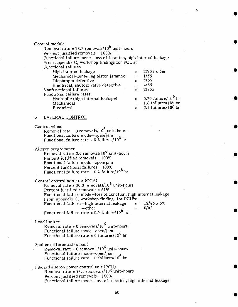
Control module •Removal rate = 28.7 removals/106 unit-hours
Percent justified removals = 100%Functional failure mode-loss of function_ high internal leakageFrom appendix C9 workshop findings for PCUVs:Functional failures
High internal leakage = 27/55 x 596 •Mechanical-centering piston jammed = 1155Diaphragm defective = 2155Electrical_ shutoff valve defective = #/55
Nonfunctional failures = 21155Functional failure rates
Hydraulic (high internal leakage) = 0.70 failure/106 hr •Mechanical = 1.6 failures/106 hrElectrical = 2.1 failures/106 hr
o LATERAL CONTROL
Control wheel •Removal rate = 0 removals/106 unit-hours
Functional failure mode.-open/jam 6Functional failure rate = 0 failures/10 hr
Aileron programmerRemoval rate = 0.# removal/106 unit-hours •Percent justified removals = 100%Functional failure mode-open/jam
•Percent functional failures = 100%Functional failure rate = 0.4 failurell06 hr
Central control actuator (CCA) •Removal rate = 30.0 removals/106 unit-hoursPercent justified removals = 61%Functional failure mode-loss of function, high internal leakageFrom appendix C_ workshop findings for PCU's:Functional failures-high internal leakage = 18/#5 x 5%
--other = 01#5Functional failure rate = 0.0 failure/10 6 hr •
Load limiterRemoval rate = 0 removals/106 unit-hoursFunctional failure mode--open/jam .Functional failure rate = 0 failures/10 b hr
Spoiler differential (mixer)Removal rate = 0 removals/106 unit-hoursFunctional failure mode--open/jamFunctional failure rate = 0 failures/106 hr
Inboard aileron power control unit (PCU) •Removal rate = 37.1 removals/106 unit-hours
Percent justified removals-- 100°,6Functional failure mode-loss of function, high internal leakage
60 •
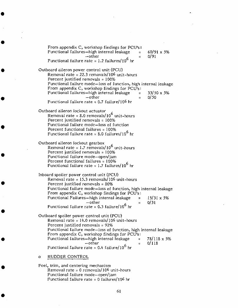
From appendix C, workshop findings for PCU's:Functional failures-high internal leakage = 60/91 x 5°,6
--other = 0/91Functional failure rate = 1.2 failures/106 hr
• Outboard aileron power control unit (PCU)Removal rate = 22.3 removals/106 unit-hoursPercent justified removals = 100%Functional failure mode--loss of function, high internal leakageFrom appendix C, workshop findings for PCU's:Functional failures-high internal leakage = 33/.50 x 5%
• --other = 0/50Functional failure rate = 0.7 failure/106 hr
Outboard aileron lockout actuator 6Removal rate = 8.0 removals/10 unit-hoursPercent justified removals = I00%Functional failure mode-loss of function
tip Percent functional failures = 100%Functional failure rate = 8.0 failures/l06 hr
Outboard aileron lockout gearbox _Removal rate = 1.7 removals/106 unit-hoursPercent justified removals = 100%
• Functional failure mode-open/jam
Percent functional failures = I00% 6Functional failure rate = 1.7 failures/10 hr
Inboard spoiler power control unit (PCU)Removal rate = 15.3 removals/106 unit-hours
• Percent justified removals = 80%Functional failure mode-loss of function, high internal leakageFrom appendix C_ workshop findings for PCU's:Functional Failures-high internal leakage : 15/31 x 5%
-other = 0/31Functional failure rate = 0.3 failure/106 hr
Outboard spoiler power control unit (PCU)Removal rate = 14.0 removals/J06 unit-hoursPercent justified removals = 92%Functional failure mode-loss of function_ high internal leakageFrom appendix C_ workshop findings for PCU's:
• Functional failures-high internal leakage = 78/118 x 5%-other = 0/I18
Functional failure rate = 0.4 failure/106 hr
o RUDDER CONTROL
• Feel, trim, and centering mechanismRemoval rate = 0 removals/106 unit-hoursFunctional failure mode--open/jamFunctional failure rate = 0 failures/106 hr
61
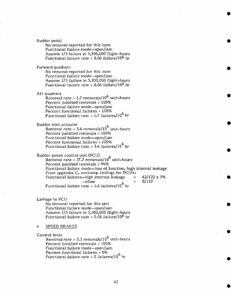
Rudder pedal •No removal reported for this itemFunctional failure mode--open/jamAssume 1/3 failure in 5_300,000 flight-hoursFunctional failure rate = 0.06 failure/J06 hr
Forward quadrant •No removal reported for this itemFunctional failure mode--open/jamAssume 1/3 failure in 5_3009000 flight-hoursFunctional failure rate = 0.06 failure/106 hr
Aft quadrant •Removal rate = 1.7 removals/106 unit-hoursPercent justified removals = I00%Functional failure mode--open/jamPercent functional failures = 100%Functional failure rate = 1.7 failures/106 hr
Rudder trim actuator •Removal rate = 3.6 removals/106 unit-hoursPercent justified rernovals= 100%Functional failure mode--open/jamPercent functional failures = 100% AFunctional failure rate = 3.6 failures/10 v hr
Rudder power control unit (PCU)Removal rate = 57.7 removals/106 unit-hoursPercent justified removals = 94%Functional failure mode--loss of function_ high internal leakageFrom appendix C, workshop Iindings Ior PCU's:Functional failures--high internal leakage = 62/122 x 5% •
--other = 0/122Functional failure rate = 1.6 failures/106 hr
Linkage to PCUNo removal reported for this unit •Functional failure mode--open/jamAssume 1/3 failure in 5_300_000 flight-hgursFunctional failure rate = 0.06 failure/10 ° hr
o SPEED BRAKES
Control leverRemoval rate = 3.3 removals/106 unit-hoursPercent justified removals = 100%Functional failure mode--open/jamPercent functional failures = 0%
Functional failure rate = 0 failures/106 hr •
62
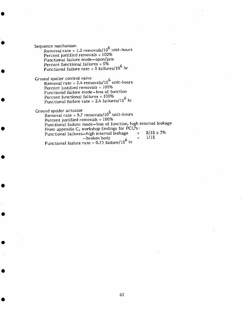
OSequence mechanism
Removal rate = 1.2 removals/106 unit-hoursPercent justified removals = 10096Functional failure mode--open/jamPercent functional failures = 096
• Functional failure rate = 0 failures/106 hr
Ground spoiler control valveRemoval rate = 2.4 removals/106 unit-hoursPercent justified removals = 100%Functional failure mode-loss of functionPercent functional failures = 100%
• Functional failure rate = 2.4 failures/10 v hr
Ground spoiler actuator removals/106Removal rate = 9.7 unit-hoursPercent justified removals = I00%Functional failure mode-loss of function_ high internal leakage
0 From appendix C, workshop findings for PCU's :Functional failures-high internal leakage = g/lg x 5%
--broken body = 1/18Functional failure rate = 0.75 failure/106 hr
63

Table 5. Functional Failure Rate Summary •Functional failure rate
Component (failuresper 106hr)
ElevatorControl column 0.0Forward quadrant 0.06Rearquadrant 0.0Rearlinkage(eachloadpath) 0.06 •Inboardelevatorpowercontrolunit 1.6Outboardelevatorpowercontrolunit 0.5Pushrodto outboardpowercontrolunit 0.06
StabilizertrimArm switch(open) 0.54 •Arm switch(closed) 0.06Controlswitch(open) 0.54Controlswitch(closed) 0.06Limit switch(open) 0.02Relay 1.30Arm lever 0.06Controllever 0.06Hydraulic motor 10.2 •Primarybrake 0.06Hydraulicbrake 1.7Ballnut 0.06Secondarynut 0.06Jackscrew(eachloadpath) D.06Shutoffvalve 3.2Geardrive(eachdifferential) 0.3 •Controlmodule (hydraulic) 0.7Controlmodule(mechanical) 1.6Controlmodule(electrical) 2.1
Lateral controlControl wheel 0.0Aileron programmer 0.4 •Central control actuator 0.4Load limiter 0.0Spoiler differential (mixer) 0.0Inboard aileron power control unit 1.2Outboard aileron power control unit 0.7Outboard aileron lockout actuator 8.0Outboard aileron lockout gearbox 1.7 •Inboard spoiler power control unit 0.3Outboard spoiler power control unit 0.4
IRuddercontrol
Feel,trim, andcenteringmechanism 0.0Rudderpedal 0.06,Forwardquadrant 0.06 •Aft quadrant 1.7Ruddertrim actuator 3.6Rudderpowercontrolunit 1.6Linkageto powercontrolunit 0.06
Speedbrakes •control lever 0.0Sequencemechanism 0.0Groundspoilercontrolvalve 2.4Groundspoileractuator 0.75
64
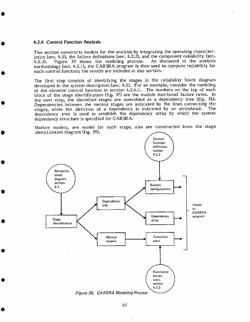
• 4.2.4 Control Function Analysis
This section constructs models for the analysis by integrating the operating character-istics (sec. 4.1), the failure definitions (sec. 4.2.2), and the component reliability (sec.4.2.3). Figure 35 shows the modeling process. As discussed in the analysismethodology (sec. 4.2.1), the CARSRA program is then used to compute reliability for
• each control function; the results are included in this section.
The first step consists ol identifying the stages in the reliability block diagramdeveloped in the system description (sec. 4.1). For an example, consider the modelingof the elevator control function in section 4.2.4.1. The numbers on the top of eachblock of the stage identification (fige 37) are the module functional failure rates. Inthe next step_ the identified stages are assembled as a dependency tree (fig. 38).
• Dependencies between the various stages are indicated by the lines connecting thestages, while the direction of a dependency is indicated by an arrowhead. Thedependency tree is used to establish the dependency array by which the systemdependency structure is specified for CARSRA.
Markov models, one model for each stage, also are constructed from the stageO identification diagram (fig. 39).
Success• configurations
Dependencytree Inputs
tO
CARSRA
Dependency programStage array
• identification
Markov "=1 Transitionmodels rates
•
Figure35. CARSRAModelingProce
65

Although stages, in general, are assembled from modules with identical failure rates, agroup of modules with different failure rates has been modeled in the study. This wasdone because the limits of the CARSRA program may be exceeded if too many stagesare modeled. An example of this approach is illustrated in figure 36. The Markovmodel shows that stage failure can occur either by a single failure from state I tostate 3 (XB) or the stage will tolerate a first failure to state 2. The transition ratefrom state 1 to state 2 (XI_ 2) has a value of 2XB, which means that two modules (AI •and A2) are operating, and any one can fail first. The transition from state 2 to state3 occurs when the remaining module A fails. This Markov model, seen by itself, shouldnot be treated as a two-module system with coverage rates as described in section4.3.1.
State 1- •
XA no failure
XB --_ AI _ X12(=2X A)
•B X ,A one failure
--_ A2 _ X23 X13(= XA) ( = X B)
Stage 1 State 3-
(Stage fails with B failed or both A 1and A 2 failed) stage failure
Markov model forstage 1
Figure 36. Markov Model With Different Modules •
The transition rates, X2_ 3 (=XA) and )'I-3 (=XB), are the functional failure rates ofmodules A and B_ respectively. All the functional failure rates for the controlfunctions have been developed in section 4.2.3.
Success configurations are the last step required to complete the input file for the •CARSRA program. These configurations state which stages may fail without causingsystem functional failure. All combinations, including single stage failures, dual stagefailures, etc., are required (this information was determined in the system definition,sec. 4.2.2).
Failure probability results from the CARSRA program indicate the probability oflosing a control function during specified exposure times. The exposure times havebeen identified as flight times ranging from I to I0 hr in l-hr increments. Actualmodel 747 operations are conducted throughout this flight length range. Each controlfunction is considered to be operational at the beginning of flight time.
The CARSRA program also computes functional readiness. For this study, afunctional readiness criterion corresponding to no module failed was established for •the elevator, stabilizer trim, lateral, and rudder control functions at successive 2-hrincrements of a flight. The results show the probability of not having a fullyoperational control function at the given stage of the flight. For the speed brakes,
66 •

• which may be required at a certain time during a flight, a functional readinesscriterion, corresponding to a combination of failed modules, was established. Thecombination is the same as that established in the control function definition for speedbrakes (sec. 4.2.2).
The use of the CARSRA program to compute the reliability of the 747 PFCS has
• necessitated a slightly different approach in modeling the system. No attempt hasbeen made to change the program itself. To verify the CARSRA results, a check is
" made against an existing analysis technique using a computer program for assessingthe reliability of redundant systems. The program, computerized reliability analysismethod (CRAM), uses system-related inputs (time period, component failure rates, andsystem success paths). It calculates the resultant system reliability.
• The assumptions for CRAM are as follows.
1. Exponential distribution applies (constant failure rate). Reliability of component iis r i .
R i = e-ritwhere ri is the failure rate for component i, and t is the time period.
2. Each component is independent of all other components.
3. Each component has two mutually exclusive states: failed and operational (notfailed).
• 4. All components are operational at the beginning of the time period.
5. Component failures are not repaired within the time period considered.
CRAM uses a modified event-space method to calculate system reliability.
• For a system with n components, there are 2n logical combinations of componentsuccess or failure that can occur. All events in this "event space" are mutuallyexclusive. To determine the system reliability, only the identity of the system successevents and the sum of the occurrence probabilities of each successful event must bedetermined.
• By systematically developing the events of the event space with respect to the numberof failed components, it is possible to reduce the number of events to be checked tomore reasonable levels and yet maintain satisfactory results. CRAM develops theevents by zero failures, one failure, two failures, .... k failures (k = 8 maximum). Ifthe component unreliabilities are fairly small, the sum of the occurrence probabilitiesof the successful events, involving K + 1 failures or more, will be so small that the
• accuracy of the final answer will not be adversely affected.
The control function failure-probability results were verified by modeling the controlfunction for the CRAM program. This consisted of using the dependency tree diagramas a success path diagram in conjunction with the success configuration. CRAMcomputes system reliability. For this analysis, the system reliability was calculatedfor a flight time of 1 hr.
The elevator and rudder control failure probabilities have been checked using CRAM.The results are included with the CARSRA results in sections 4.2.4.1 and 4.2.4.4.
67
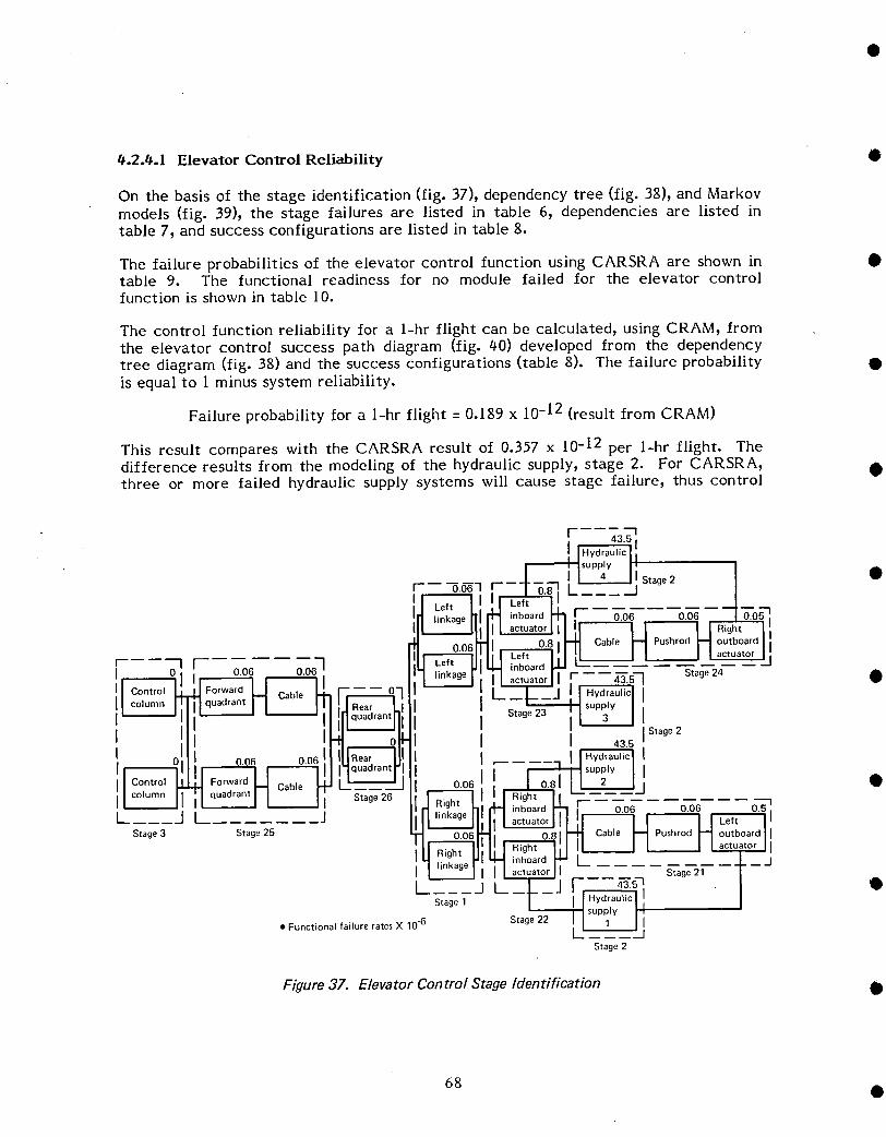
#.2.t¢.1 Elevator Control Reliability •
On the basis of the stage identification (fig. 37), dependency tree (fig. 38), and Markovmodels (fig. 39), the stage failures are listed in table 6, dependencies are listed intable 7, and success configurations are listed in table 8.
The failure probabilities of the elevator control function using CARSRA are shown in •table 9. The functional readiness for no module failed for the elevator controlfunction is shown in table 10.
The control function reliability for a l-hr flight can be calculated, using CRAM, fromthe elevator control success path diagram (fig. 40) developed from the dependencytree diagram (fig. 38) and the success configurations (table 8). The failure probability •is equal to 1 minus system reliability.
Failure probability for a 1-hr flight = 0.189 x l0 -12 (result from CRAM)
This result compares with the CARSRA result of 0.357 x 10⁻¹² per 1-hr flight. Thedifference results from the modeling of the hydraulic supply, stage 2. For CARSRA, •three or more failed hydraulic supply systems will cause stage failure, thus control
r i, 43.5 t
, lL_2__Jlstag 2 I •
Ol I oo6 oo6 ...... l
•I °-°61 •RightI-I -! in;oa__ _--0_' o.06 0.51I Stage26 -- -- --
Stoge II
_1 I Jj •
Stage 1
• Functional failure ratesX 10.6 Stage22 I I 1 I II' 'J
Stage2
Figure 37. Elevator Control Stage Identification •
68 •
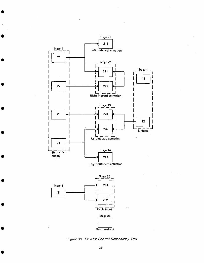
• Stage21
LI"1 21, I
Stage2 Left outboard actuationr ]
I 21 I 1• I Stage22
I I "J 221 Stage1I I i!
3
11 I
I /I !LI I• I 22 I /Ol 222 III L" } I
I I Right inboardactivation II II I Stoge23 I I
• I I r i
'[ I, ',r '23 , 2al I I
, '[I I I:l 232 [ II I I I'I L_nkage• I I Left inboard actuation
'l 2,k J Stage_Hydraulic
• supply Ji 241 _Rightoutboardactuation
Stage25
• [j =]3 . 251 I J
I!J!'1 252 IL' J . .
Cable input
Stage 26
I• Rearquadrant
Figure 38. Elevator Control Dependency Tree
69
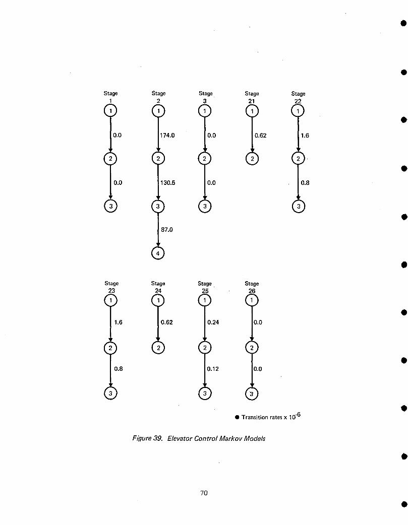
Stage Stage Stage Stage Stage2 3 21 22
() () () () (:)o
0.0 174.0 0.0 0.62 1.6
0.0 130.5 0.0 0.8
87.0
Stage Stage Stage Stage23 24 25 26
() () () ()1.6 0.62 0.24 0.0
d) (,:) (,:) d)0.8 0.12 0.0
(,) (_) (:)• Transition ratesx 10-6
Fiiqure39. Elevator Control Markov Models
7O

Table 6. Elevator Control Stage Failures
O StageNo. Stagedescription Stagefailure
Dependentstages
1 Linkageto left andright inboard Stagefailswith fourth loadpathfailureelevators of the two linkages
2 Hydraulicsupply Stagefailswith thirdhydraulicsupply• systemfailure
3 Controlcolumn Stagefailswith secondcontrolcolumnfailure
Nondependentstages
21 Left outboardelevatoractuation Stagefailswith cable,pushrod,or actuatorfailure
22 Right inboardelevatorpower Stagefailswith secondactuatorfailurecontrolunit
23 Left inboardelevatorpower Stagefailswith secondactuatorfailurecontrolunit
24 Rightoutboardelevatoractuation Stagefailswith cable,pushrod,or actuatorfailure
25 Cableandforwardquadrant Stagefailswith secondcable/quadrantfailure
26 Aft quadrant Stagefailswith secondloadpathof aftquadrantfailure
0 Table 7. Elevator Control Module Dependencies
Dependent Nondependentmodules modules
11 _ 221,222
12 _ 231,232
• 21 _ 211,221
22 _ 222
23 _ 231
24 _ 232, 241
Q 31 _ 251,252
• 71
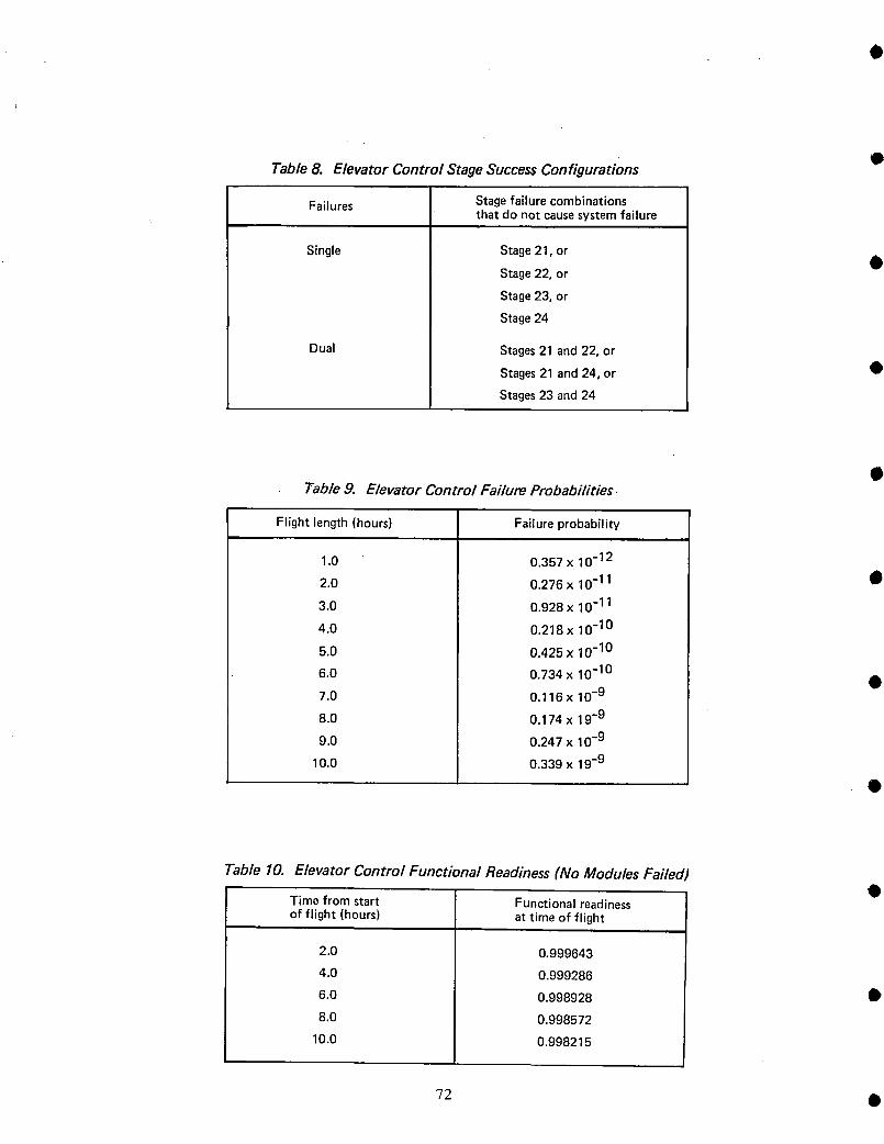
Table8. ElevatorControl StageSuccessConfigurations •
Failures Stagefailurecombinationsthat do notcausesystemfailure
Single Stage21, or 0Stage22, or
Stage23, or
Stage24
Dual Stages21 and22, or
Stages21 and 24, or •
Stages23 and24
Table 9. Elevator Control Failure Probabilities •
Flight length(hours) Failureprobability
1.0 0.357 x 10⁻¹²
2.0 0.276 x 10⁻¹¹ O
3.0 0.928 x 10⁻¹¹
4.0 0.218 x 10⁻¹⁰
5.0 0.425 x 10⁻¹⁰
6.0 0.734 x 10⁻¹⁰
7.0 0.116 x 10.9
8.0 0.174 x 19-9
9.0 0.247 x 10⁻⁹
10.0 0.339 x 19-9
Table 10. Elevator Control Functional Readiness (No Modules Failed)
Time from start Functional readinessof flight (hours) at time of flight
2.0 0.999643
4.0 0.999286
6.0 0.998928 0
8.0 0.998572
10.0 0,998215
72 •
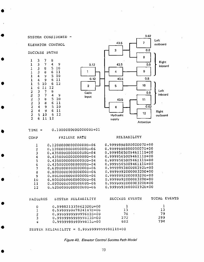
• SYSTEM CONSIDERED - 0.62
43"5 Ir'_ 7 I LeftELEVATOR CONTROL outboard
SUCCESS PATHS _ 3 _ 8081• 1 3 7 8 Rightl 3 7 4 9 0.12 43.5 0.8 inboard
I 4 9 5 i0
1 4 9 6 ii 0.1 435 08
i 6 ii I2 2 5 10
2 3 7 8 Cable 0.8 Left2 3 7 4 9 input / I inboard
2 3 _ 5 10 435 _ 11 IO 2 4 9 5 10 6 _ 0.62
249611 I_ I Right2 5 10 6 12 Hydraulic 12 outboard2 61112 supply
Actuation
TIME = 0.100000000000000D+01
COMP FAILURE RATE RELIABILITY
1 0.120000000000000D-06 0.999999880000007D+00
2 0.120000000000000D-06 0.999999880000007D+00
3 0.435000000000000D-04 0.999956500946111D+00• 4 0.435000000000000D-04 0.999956500946111D+00
5 0.435000000000000D-04 0.999956500946111[)+006 0.435000000000000D-04 0.999956500946111D+007 0.620000000000000D-06 0.999999380000192D+00
8 0.800000000000000D-06 0.999999200000320D+009 0.806000000000000D-06 0.999999200000320D+00
• i0 0.800000000000000D-06 0.999999200000320D+00ii 0.800000000000000D-06 0.999999200000320D+00
12 0.620000000000000D-06 0.999999380000192D+00
FAILURES SYSTEM RELIABILITY SUCCESS EVENTS TOTAL EVENTS
0 0.999821335962320D+00 1 11 0.999999987824187D+00 13 13
2 0.999999999999601D+00 78 793 0.999999999999811D+00 272 2994 0.999999999999_iIu+00 602 794
SYSTEM RELIAEILITY = 0.999999999999811D+00
Figure 40. Elevator Control SuccessPath Model
• 73

Ofunction failure. CRAM computes reliability by specifying exact success configura-tions. The elevator control system has four success paths where three hydraulic supplysystems can fail without control function failure. These success paths (1=3=7=8, 1=6=ll=12, 2=3=7-8, and 2-6=11-12) correspond to successful operation of one inboardelevator and the opposite outboard elevator when only one hydraulic supply system(number l or 4) is available. In all other success configurations, at least two hydraulic •systems are needed to maintain the control function.
To model these success configurations, some with two hydraulic systems failed andothers with three hydraulic systems failed, for CARSRA, each hydraulic supply systemmust be in a separate stage. This approach, however, "does not make use of thefeatures for which CARSRA was designed: the ability to group like modules in a singlestage. •
#.2._.2 Stabilizer Trim Reliability
On the basis of the stage identification (fig. #l), dependency tree (fig. 42), and Markovmodels (fig. 43), the stage failures are listed in table l l, dependencies are listed intable 12, and the success configurations are listed in table 13. •
The failure probabilities of the stabilizer trim function using CARSRA are shown intable l#. The functional readiness for no module failed for the stabilizer trim functionis shown in table 15.
I'l 1.6
I IC°ntr°'I, l!Imodule I- _
r- ........... -I [ I I (mechanical)JlI 108 1.31 , 2.1 Ii I I -A;I ontro'II a II arm/control I-I Relay It] r-t-i module I0.12 0.12 I 0.24 0.02 I I
IPilot/copilotl _ switch°pen]l liH II (electrical) III arm/control M switch 1" 1.08 ____.3 I [-I :, 2.1I I •
I switchclosedl I I Copilot II-- --IIII !1 c°ntr°i II I i/I arm/control I-I Helay _ _ module I II switch open I I I I il (electrical) i I 1.6, , - - II Control I!F B
Stage 25 I I moduler I Stage 26 Stage 22 I (mechanical) li
43.5 I-- _ _ _ _ OI I Stag021I I r I I-_--"1
I ,!'0.70 , 3.2 4,1o.2I $1.71 I 0.30 I 0.06 0.06
A-;-Imodu,eI--ISh< I IilI (hydrau'iclI I "al' I I i,_._.__£_ •I 070 3.210.2 It _ I p_._2i I [
B--]-I module H -:- I I I
i I ihydraulic) val_? I[__, I i t----.A _I Stage24 I I
I I L__J L. - •I F aul-'_c I Stage 23 Stage 27 Stage 28
I I_PP '/ I I • Functional failure rates x 10.6L-- 1_' _.J Stage 1
Figure 41. Stabilizer Trim Stage Identification
'74 Q
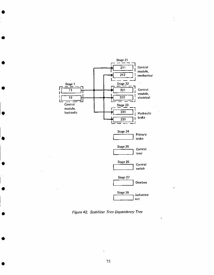
Stage21
{'1 211 Controlmodule,I mechanical
212 I jStage1 Stage22
i_ {I 11 _-I ,, _ 221 I ]1Control
I I I rl ,
rL_ ] module,III 12 III _: 222 I electrical.
Control Stage 23
module, _ ,]• hydraulic i _1 231 I I Hydraulic
I brake231 Ij
Stage24Primary
• I I brake
Stage25
I I C°ntr°llever
Stage26 Control• I I switch
Stage27
I I Gearb°x
Stage28 JackscrewI Inut
• Figure 42. Stabilizer Trim Dependency Tree
• 75
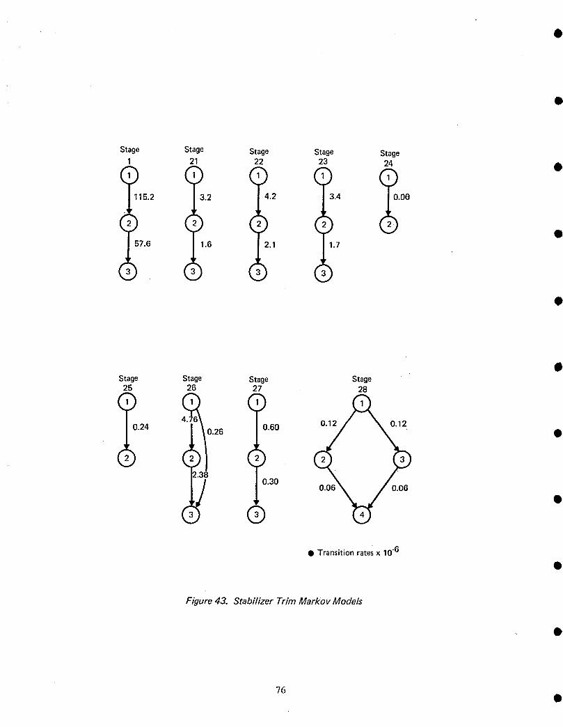
Stage Stage Stage Stage Stage
21 22 23 24 0
115.2 3.2 4.2 3.4 .0e
r r r
57.6 1.6 2.1 1.7
0Stage Stage Stage Stage25 26 27 28
4.76 %
0.24 0.26 0.60 •
, .,)
2.3/ '0.30 0.06 _// 0.06
, •
Q Transition ratesx 10.6
Figure 43. Stabilizer Trim Markov Models
?6
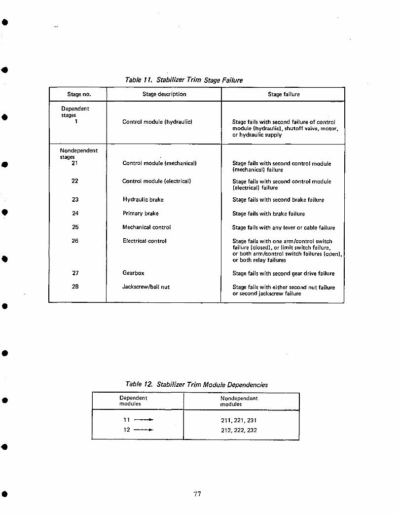
OTable 11. Stabilizer Trim Stage Failure
Stageno. Stagedescription Stagefailure
Dependent
• stages1 Controlmodule(hydraulic) Stagefailswith secondfailureof control
module(hydraulic),shutoffvalve,motor,or hydraulicsupply
Nondependentstages
• 21 Controlmodule(mechanical) Stagefailswith secondcontrolmodule(mechanical)failure
22 Controlmodule(electrical) Stagefailswith secondcontrolmodule(electrical)failure
23 Hydraulicbrake Stagefailswith secondbrakefailure
• 24 Primarybrake Stagefailswith brakefailure
25 Mechanicalcontrol Stagefailswithany leveror cablefailure
26 Electricalcontrol Stagefailswith onearm/controlswitchfailure(closed),or limit switchfailure,or botharm/controlswitchfailures(open),
• or bothrelayfailures
27 Gearbox Stagefailswith secondgeardrivefailure
28 Jackscrew/ballnut Stagefailswith eithersecondnut failureor secondjackscrewfailure
Table 12. Stabilizer Trim Module Dependencies
• Dependent Nondependentmodules modules
11 _ 211,221,231
12 _ 212,222,232
• 77
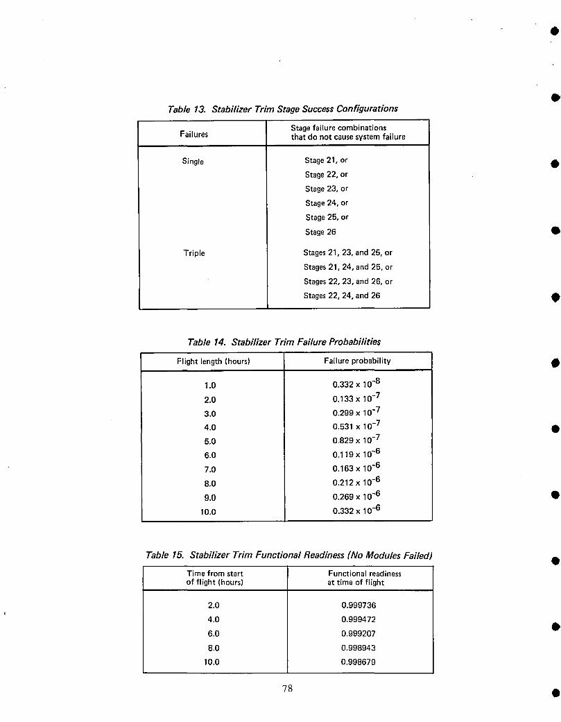
DTable 13. Stabilizer Trim Stage Success Configurations
StagefailurecombinationsFailures that do notcausesystemfailure
Single Stage21, or 0Stage22, or
Stage23, or
Stage24, or
Stage25, or
Stage26 •
Triple Stages21, 23, and 25, or
Stages21, 24, and 25, or
Stages22, 23, and 26, or
Stages22, 24, and26
Table 14. Stabilizer Trim Failure Probabilities
Flight length (hours) Failureprobability
1.0 0.332 x 10⁻⁸
2.0 0.133 x 10⁻⁷
3.0 0.299 x 10⁻⁷
4.0 0.531 x 10⁻⁷ •5.0 0.829 x 10⁻⁷
6.0 0.119 x 10~6
7.0 0.163 x 10⁻⁶
8.0 0.212 x 10⁻⁶
9.0 0.269 x i0 -6 •
10.0 0.332 x 10⁻⁶
Table 15. Stabilizer Trim Functional Readiness (No Modules Failed) •Time from start Functional readinessof flight (hours) at time of flight
2.0 0.999736
4.0 0.999472
6.0 0.999207 •
8.0 0.998943
10.0 0.998679
78 •
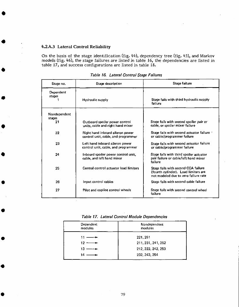
4.2.4.3 Lateral Control Reliability
On the basis of the stage identification (fig. 44), dependency tree (fig. 45), and Markovmodels (fig. 46), the stage failures are listed in table 16, the dependencies are listed intable 17, and success configurations are listed in table 18.
Table 16. Lateral Control Stage Failures
Stageno. Stagedescription Stagefailure
Dependent
• stages1 Hydraulicsupply Stagefailswith third hydraulicsupply
failure
Nondependentstages
21 Outboardspoilerpowercontrol Stagefailswith secondspoilerpairor• units,cableandright handmixer cable,or spoiler mixer failure
22 Righthandinboardaileronpower Stagefailswith secondactuatorfailure 'controlunit, cable,andprogrammer or cable/programmerfailure
23 Left handinboardaileronpower Stagefailswith secondactuatorfailurecontrolunit, cable,andprogrammer orcable/programmerfailure
• 24 Inboardspoilerpowercontrolunit, Stagefailswith third spoileractuatorcable,andleft handmixer pairfailureor cable/lefthandmixer
failure
25 Centralcontrolactuatorloadlimiters Stagefailswith secondCCA failure(fourth cylinder). Loadlimitersarenot modeleddueto zerofailurerate
• 26 Input control cables Stagefails with secondcablefailure
27 Pilotandcopilotcontrolwheels Stagefailswith secondcontrolwheelfailure
Table 17. Lateral Control Module Dependencies
Dependent Nondependentmodules modules
• 11 _ 221,25112"_"_ 211,231,241,252
13 _ 212,222,242,253
14 _ 232,243,254
• 79
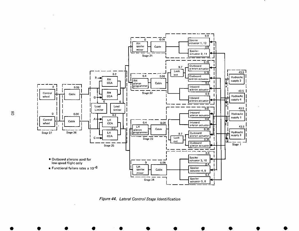
[ 0.8 1
0 0.06 _._.J Spoiler L_
.I RH II I I qactuator1,12I_ I1_1 spoiler I_1 Cable _ " 0.8" IJl m,xer L. j I I I SP°iler /
S%ge_; ] _ aotuator2.,,I o.35 I
II 97 J Outboard
N aileron actuator
r o2 r ! -I _-_2-H 0.35 43.51
I_ t_Ji I" 0"4 0"06 I uu[ IUOutb°ard I
I RH " " , _laileron actuator
c_HA flo,eronI-I Cab'e! 0.6 I
---iC'_ _--O_IL_- 0.06 W _'JI I Ilpr_rammerl I I ...,._ Inboard I
, ..... ,rl°l _ Cable _/i r_ cRHA Stage 22 q "_-I 0.6 43"51
I [_"l aileron actuator, , ! u'[-_lO I 0 I I . ' 'Inboard
I =1,oa_II Loa_!II II Umiter II limiter I F ....... _0._" 43.5% o I .---1_
._1_[ ._ttCa_ "061 l" 1" "0.2_ ' , , , aileron actuator
[ S_:_:II _" _ i I ---- 0'_ ---- 0"06 I I I_
I LH 11 II ----"lailer°n actuator 43.52 I aileron !"1 Cable I"t 0.35
6 IPr°grammerlI H 97 J_
---- _1_ rl ai,oronactuator• _ -- Stage 23 ; LI L,_ I-.I " 0.35
St aileron actuatori I °u_ I q Outb°ard Stage,
[ 0.4 II ,_J Spoiler
• Outboardaileronsusedfor I I lactuator3,10low-speedflightonly I 0 0.O6 _- "6.4LH
I Functionalfailure ratesx 10-6 JJ spoiler U Cable I I I_-- --
/ .mixer H I I , actuator 4,9
Stage 24 I _ Spoiler
L___ I actuat°r5' 8 I
Figure 44. Lateral Control StageIdentification
• • t I • • • • • • •
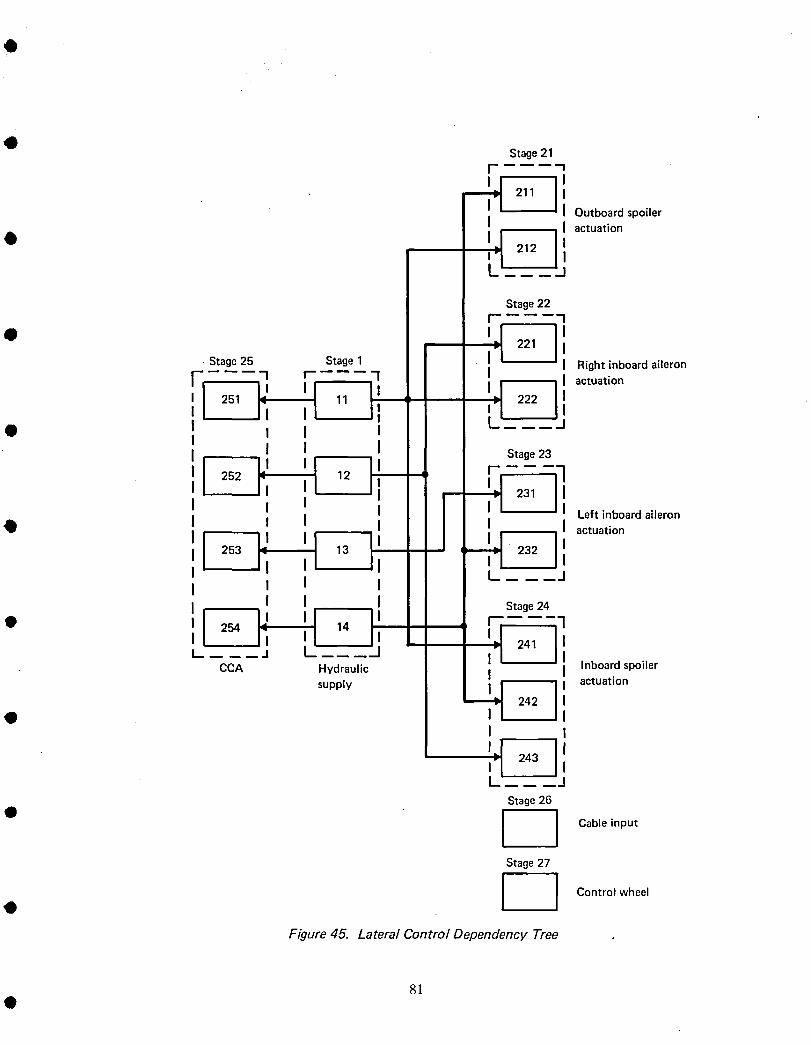
O
• Stage21I 1I I
II Outboard spoiler
I I actuation• t
IJ
Stage22f
• Stage25 Stage1 Right inboardaileron] = II I actuation
11I I
@ t I II I I Stage23
I i ]I I II I I I Left inboardaileron
• I I I I I actuationI I I
I I It__ __JI I II I I Stage24
I IJ t l@ 254 - 14
CCA Hydraulic Inboardspoilersupply actuation
• II
II.=1 243 ItStage26
• I I Cable input
Stage27
i [ Control wheel
Figure 45. Lateral Control Dependency Tree
81
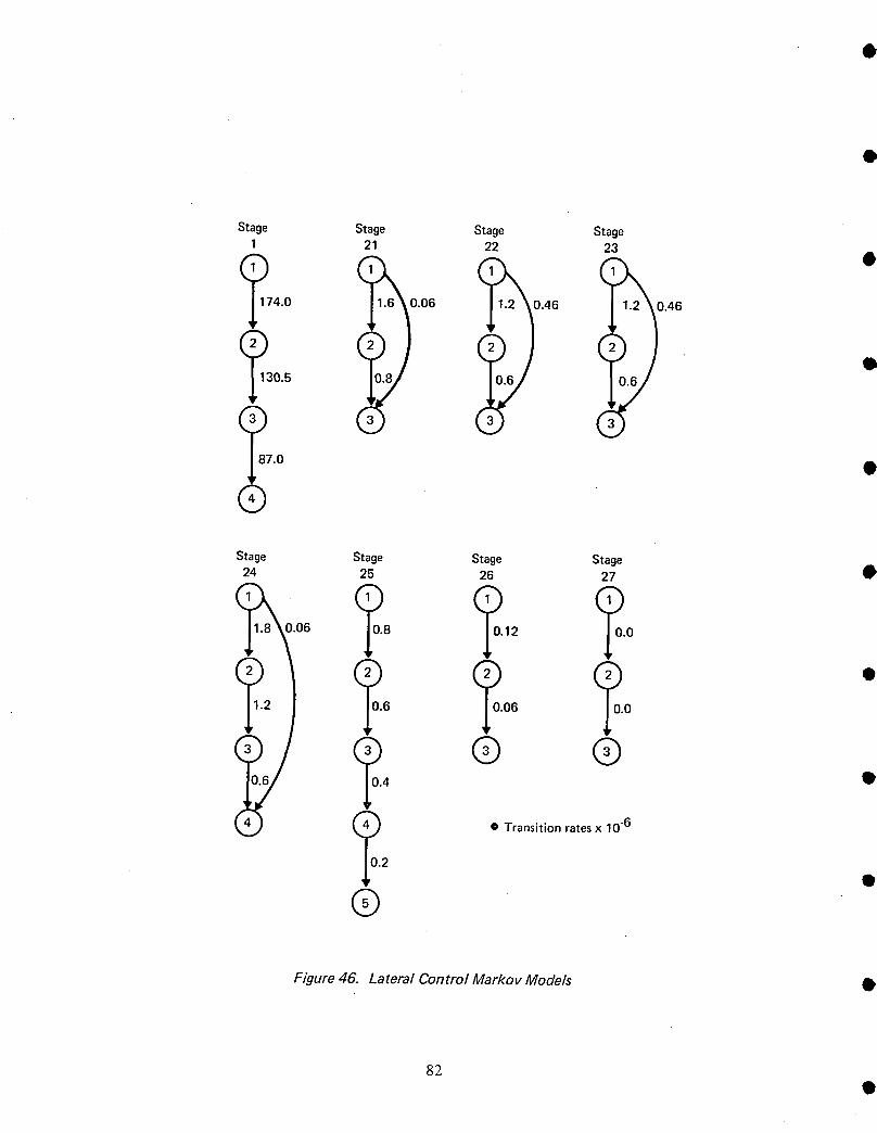
Stage Stage Stage Stage
1 21 22 23 •
174.0 0.06 0.46 .46
0.5
_87.0 •
®
Stage Stage Stage Stage24 25 26 27 •
0.06 _0.8 _0.12 _0.0
o.o •_0. • Transition ratesx 10 "6
2
0
®
Figure 46. Lateral Control Markov Models •
82

QTable 18. Lateral Control StageSuccessConfigurations
StagefailurecombinationsFailures thatdonotcausesystemfailure
• Single Stage21,orStage22,or
Stage23,or
Stage24
• Dual Stages22and23,orStages21and24,or
Stages23and24,or
Stages21and23,or
Stages22and24,or
• Stages21and22
The failure probabilities of the lateral control function using CARSRA are shown intable 19. The functional readiness for no module failed for the lateral control functionis shown in table 20.
To check the failure probability of the lateral control function for the low-speed case)the outboard ailerons are included in the model. Stages 22 and 23 are changed toinclude the aileron lockout system and the outboard actuators (table 21). Figure 47shows the revised Markov models for these two stages.
• The failure probability of the lateral control function) which includes the outboardailerons for a I-hr flight_ is 0.355 x l0 -12. Comparison of the low-speed case to thegeneral case shows only a slight degradation in reliability.
Table 19. Lateral Control Failure Probability
• Flightlength(hours) Failureprobability
1.0 0.341x 10⁻¹²
2.0 0.266x 10⁻¹¹
3.0 0.894x 10⁻¹¹
• - 4.0 0.211x 10-105.0 0.412x 10⁻¹⁰
6.0 0.712x 10⁻¹⁰
7.0 0.113x 10⁻⁹
8.0 0.169x 10⁻⁹
• 9.0 0.240x 10⁻⁹
10.0 0.329x 10⁻⁹
• 83

Table 20. Lateral Control Functional Readiness (No Modules Failed) •
Time from start Functional readinessof flight (hours) at time of flight
2.0 0.999637
4.0 0.999273 •
6.0 0.998910
8.0 0.998547
10.0 0.998184
Table 21. Lateral Control Stage Failures (Low-Speed Case)
StageNo. Stagedescription Stagefailure
22 Right handinboardandoutboardaileronpower Stagefails with the fourth actuatorfailure, •controlunit, cable,programmer,andlockout lockoutsystem,cableor programmerfailure
23 Left handinboardandoutboardaileronpower Stagefailswith the fourthactuatorfailure,controlunit,cable,programmer,andlockout lockoutsystem,cableor programmerfailure
Stage Stage22 23
\ •O.'t
10.2 _'_"t10.2_5/
• Transitionratesx 10"6
Figure 47. Lateral Control Markov Models for Outboard Ailerons •
84 •

• t_.2.#.t_ Rudder Control Reliability
On the basis of the stage identification (fig. 48), dependency tree (fig. t_9), and Markovmodels (fig. 50), the stage failures are listed in table 22, the dependencies are listed intable 23, and success configurations are listed in table 24.
0 Table 22. Rudder Control Stage Failures
StageNo. Stagedescription Stagefailure
Dependentstages
1 Linkageto powercontrolunits Stagefails with secondlinkagefailure
2 Hydraulicsupply Stagefailswith fourthhydraulicsupplysystemfailure
Nondependentstages
21 Upperand lower rudderpower •Stagefailswith fourth actuatorfailurecontrolunits
22 Ruddertrim input Stagefailswith trim/actuator/cable/trim knobfailure
23 Rudderpedalinput Stagefailswith secondrudderpedal failureor forwardquadrant/cable/aftquadrant
'0 failure
24 Feel,trim, andcenteringunit Stagefailswith secondloadpathfailureof feel, trim, andcenteringunit
Q Table 23. Rudder Control Module DependenciesDependent Nondependentmodules modules
11 _ 221,251
12--------_ 211,231,241,252
• 13---_ 212,222,242,253
14-------_ 232,243,254
Table 24. Rudder Control Stage Success Configurationst
Failures Stagefailure combinationsthat do not causesystemfailure
Single Stage22, or
Stage23
• 85

.JStage23
• Functional failure ratesx 10-6 I Rudder I I RudderIJpedal J J pedalJ e
Stage22 0.061 I o.o6
r o , Io_i I Tr,ml= _o_aroknob J quadrant
_ I0.00I I0.* °
i I_.01 I1.,I I Trim I I AftI I
I actuatorI ' I quadrantI •L--I- -J I
I
[S,oge24 J --II !o Io I •
, 'J centering centering J
I I j j
r Io.oo 1 "Linkage J Stage1 Linkage-i ]-
'1 il I I ILower Lower Upper actuatorJ actuator actuator 0c,_a,o_J°°_°_I I
-,t t ,I 5 , 43.5 _ _ •
I I Hydraulic I I Hydrau'ieI I Hydraulic I I Hydraulic IJ supply4 supply2 supply3 supply1
l Stage2 J
Figure 48. Rudder Control Stage Identification
86 •
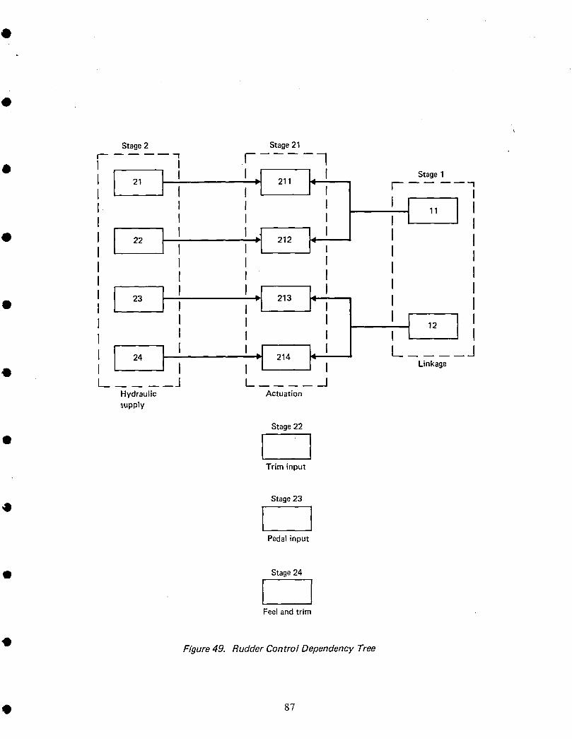
O . .
t
Stage2 Stage21
1 r 1I
• I 21 ] I I I.= 211 LI Stage1I I rtI I I I 11 II I I I I
d 1' '• 22 I I 212
I I t II I I I
I I I 'I I
• 23 I '=i 213 i: ', I II I II I I I J 12 II I I I 1 I
I _ I Lt / _124 -= 214
• I I J'l Linkage..... J I _J
Hydraulic Actuationsupply
Stage22
• ITrim input
Stage23
° IPedalinput
Q Stage24
I IFeel andtrim
• Figure 49. Rudder Control Dependency Tree
• 87

Stage Stage Stage Stage •1 2 21 22
43.5 8
O
Stage Stage23 24
•.82 0
rates x k,_,/_0.0 •• Transition 10-6 ('_
Figure 50. Rudder Control Markov Models
88 •

t
Q The failure probabilities of the rudder control function using CARSRA are shown intable 25. The functional readiness for no module failed for the rudder control functionis shown in table 26.
The control function reliability for a 1-hr flight can be calculated using CRAM fromthe rudder success path diagram (fig. 51) developed from the dependency tree diagram
O (fig. 49) and the success configurations (table 24). The failure probability is equal toI minus system reliability.
Failure probability for a l-hr flight = 0.6666 x I0 -II (result from CRAM)
This result compares closely with the CARSRA result of 0.6672 x 10-I I per l-hr flight.• In this case, the hydraulic supply failure combination for system failure with the
fourth supply failure is the same for both CARSRA and CRAM.
Table 25. Rudder Control Failure Probabilities
Flightlength(hours) Failureprobability
1.0 0.667x 10⁻¹¹
2.0 0.267x 10⁻¹⁰
3.0 0.600x 10⁻¹⁰
4.0 0.107x 10⁻⁹
• 5.0 0.167x 10⁻⁹
6.0 0.240x 10⁻⁹
7.0 0.327x 10⁻⁹
8.0 0.427x 10⁻⁹
• 9.0 0.540x 10-910.0 0.667x 10⁻⁹
• Table 26. Rudder Control Functional Readiness(No Modules Failed)
Time from start Functional readiness
of flight (hours) at time of flight
2.0 0.999634
t 4.0 0.9992696.0 0.998903
8.0 0.998538
10.0 0.998172
• 89
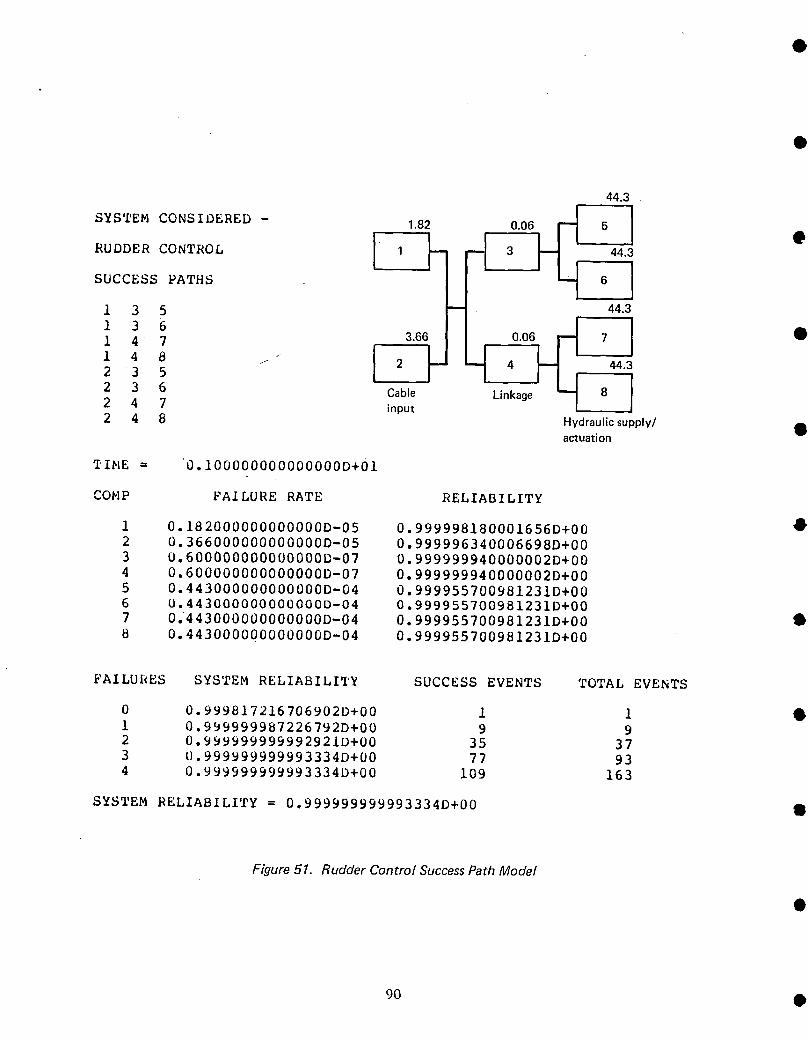
44.3
SYSTEM CONSIDERED - 1.82 _5 1RUDDER CONTROL 3
SUCCESS PATHS
1 3 5 _ 44.3
1 47 3.66 7 •
,' J ! ,2 3 6 Cable Lmk_e _ 8 I2 4 7 input / I2 4 8 Hydraulicsupply/ •actuation
TINE = 0.!00000000000000D+01
COMP FAILURE RATE RELIABILITY
1 0.182000000000000D-05 0.999998180001656D+00 •
2 0.366000000000000D-05 0.999996340006698D+00
3 0.600000000000000D-07 0.999999940000002D+004 0.600000000000000D-07 0.999999940000002D+00
5 0.443000000000000D-04 0.999955700981231D+006 0.443000000000000D-04 0.999955700981231D+007 0.443000000000000D-04 0.999955700981231D+00 •
8 0.443000000000000D-04 0.999955700981231D+00
FAILURES SYSTEM RELIABILITY SUCCESS EVENTS TOTAL EVENTS
0 0.999817216706902D+00 1 1 •1 0.999999987226792D+00 9 92 0.999999999992921D+00 35 37
3 0.999999999993334D+00 77 934 0.999999999993334D+00 109 163
SYSTEM RELIABILITY = 0.999999999993334D+00 •
Figure 51. Rudder Control SuccessPath Model
90 •
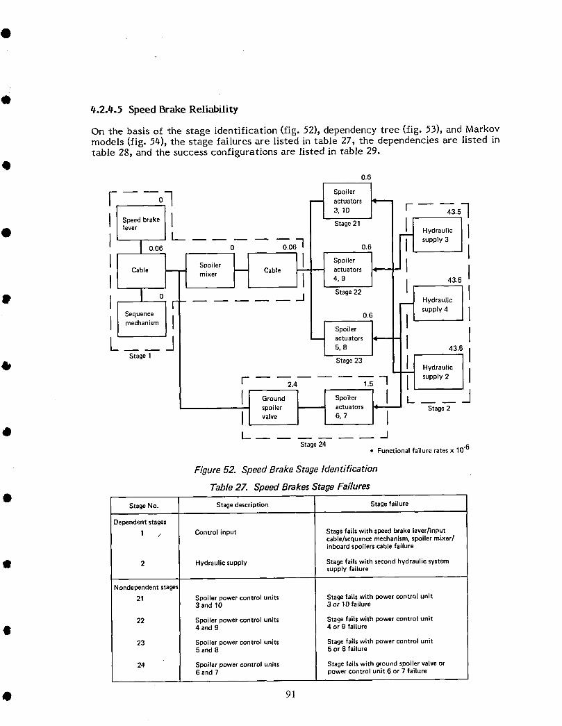
Q_.2.4.5 Speed Brake Reliability
On the basis of the stage identification (fig. 52), dependency tree (fig. 53), and Markovmodels (fig. 54), the stage failures are listed in table 27, the dependencies are listed intable 28, and the success configurations are listed in table 29.
Q0.6
0 actuators
Speed brake
O lever Stage21 HydraulicL_ . supply 3
I 0.06 0 0.061 0.6 I
I H ICable -- mixer Cable actuators
4, 9 43.5
• ,0 , s'ge2I'Hydraulicsupply 4
Sequence 0.6 Imechanism
oo ,,o or,I I5,8 43.5
Stage 1 I
_IP Stage23 I I
Hydraulic
[ 2.4 1.5 I supply 2
It Gr°und _ Sp°iler _1 / J
spoiler actuators Stage2
valve 6, 7
• L ...... JStage 24
• Functional failure ratesx 10-6
Figure 52. SpeedBrake Stage Identification
Table 2Z SpeedBrakesStage Failures
StageNo. Stagedescription Stage failure
Dependent stages
1 / Control input Stage fails with speed brake lever/inputcable/sequencemechanism,spoiler mixer/inboard spoilerscable failure
• 2 Hydraulic supply Stagefails with secondhydraulic systemsupply failure
Nondependent stages
21 Spoiler power control units Stage fails with power control unit3 and 10 3 or 10 failure
22 Spoiler power control units Stage fails with power control unit
4 and 9 4 or 9 failure
23 Spoiler power control units Stage fails with power control unit5 and 8 5 or 8 failure
24 Spoiler power control units Stage fails with groundspoiler valve or6 and 7 power control unit 6 or 7 failure
91

OStage 21
-_ 211 14 Stage 2
[II 2I
Stage 22 I
__ 221I IStage 1 I 0
11 1_ II 22ICable Stage 23 I
input "_ 231 _ II 11II 23
Stage 24 -_L I
I _ Hydraulic-" 241 supply ti_
Actuation
Figure 53. Speed Brake Dependency Tree •
Table 28. SpeedBrake Module Dependencies
Dependent Nondependent •modules modules
11 "_ 211,221,231,241
21 -_ 221
22-_--_ 231,241 •23------_ 211
92 •
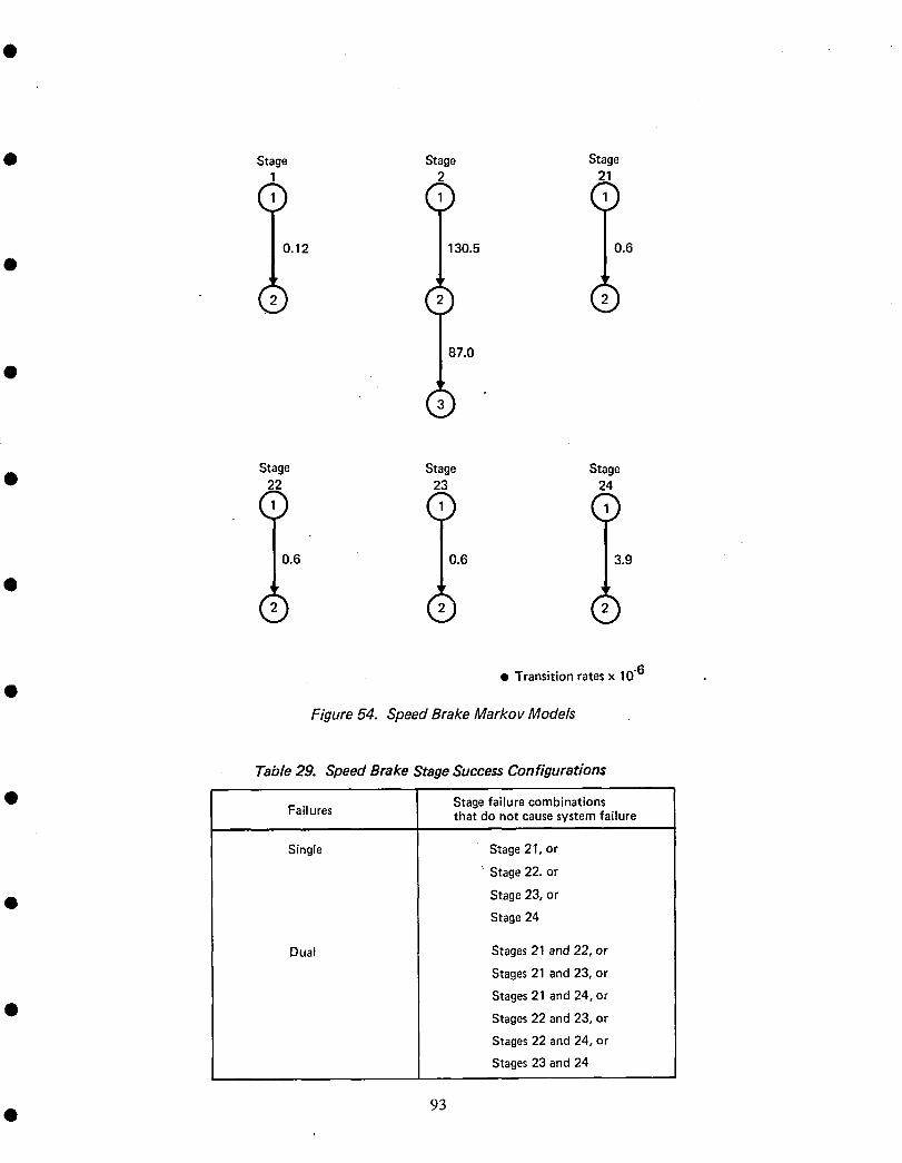
4D Sta e Stage Stage2 21
() () ()0.12 130.5 0.6
o
87.0
F
Stage Stage Stage• 22 23 24
0.6 0.6 3.9
• Transitionratesx 10-6
Figure 54. Speed Brake Markov Models
Table 29. Speed Brake Stage Success Configurations
• StagefailurecombinationsFailures that do notcausesystemfailure
Single Stage21, or
' Stage22. or
• Stage23, orStage24
Dual Stages21 and 22, or
Stages21 and23, or
Stages21 and24, or
• Stages22 and23, or
Stages22 and24, or
Stages23 and24
• 93
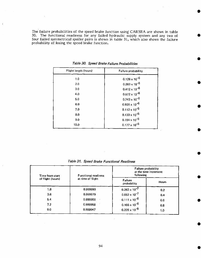
The failure probabilities of the speed brake function using CARSRA are shown in table30. The functional readiness for any failed hydraulic supply system and any two of •four failed symmetrical spoiler pairs is shown in table 31_ which also shows the failureprobability of losing the speed brake function.
Table 30. Speed Brake Failure Probabilities
Flight length (hours) Failure probability
1.0 0.126 x 10⁻⁶
2.0 0.263 x 10⁻⁶ •
3.0 0.412 x 10⁻⁶
4.0 0.572 x 10⁻⁶
5.0 0.743 x 10⁻⁶
6.0 0.926 x 10⁻⁶ •7.0 0.112 x 10⁻⁵
8.0 0.133 x 10⁻⁵
9.0 0.154 x 10⁻⁵
10.0 0.177 x 10⁻⁵
Table 31. Speed Brake Functional Readiness
Failure probabilityat the time increment
Time fromstart Functionalreadiness following •of flight (hours) at time of flight Failure
probability Hours
1.8 0.999990 0.283 x 10⁻⁷ 0.2
3.6 0.999979 0.653 x 10⁻⁷ 0.4
5.4 0.999968 0.111 x 10⁻⁶ 0.6 •
7.2 0.999958 0.165 x 10⁻⁶ 0.8
9.0 0.999947 0.228 x 10⁻⁶ 1.0
94 •
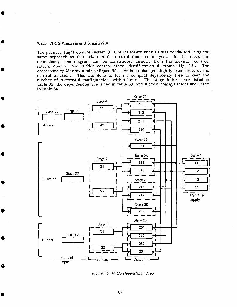
• 0.2.5 PFCS Analysis and Sensitivity
The primary flight control system (PFCS) reliability analysis was conducted using thesame approach as that taken in the control function analyses. In this case, thedependency tree diagram can be constructed directly from the elevator control,lateral control, and rudder control stage identification diagrams (fig. 55). The
• corresponding Markov models (figure 56) have been changed slightly from those of thecontrol functions. This was done to form a compact dependency tree to keep thenumber of successful configurations within limits. The stage failures are listed intable 32, the dependencies are listed in table 33, and success configurations are listedin table 34.
Stage21
• P Stage 4 [_I 1
f I _ 211 1_Stage30 Stage29 I i
41212
I II I= I• Aileron Ill 42 _ 213214
Stage 22
-- r_ 221
• Stage23 Stage 1
Stage2 3[ 231 11II 21 232 12
Stage27 I
Elevator I I I I Stage 24 13
• I [_ _!I 241 14
d "
22 I 242 Hydraulicsupply
Stage 25
0 251m
Stage26-- Stage3
i i_ 261Stage28 I [ 31 I 262
• Rudder I I I 263
-- 264 jm I_ Control _j I_ Linkage ---J L Actuation--_J
input
0Figure 55. PFCSDependency Tree
• 95
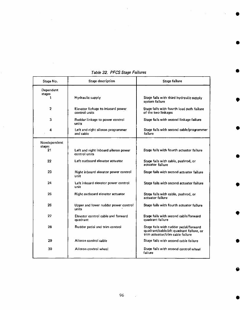
Table 32. PFCS Stage Failures Q
StageNo. Stagedescription Stagefailure
Dependentstages
1 Hydraulicsupply Stagefails with third hydraulicsupply _)systemfailure
2 Elevatorlinkageto inboardpower Stagefailswith fourth loadpathfailurecontrolunits of the two linkages
3 Rudderlinkageto powercontrol Stagefailswith secondlinkagefailureunits
4 Left andrightaileronprogrammer Stagefailswith secondcable/programmer Oandcable failure
Nondependentstages
21 Left andright inboardaileronpower Stagefailswith fourth actuatorfailure
control units •22 Left outboardelevatoractuator Stagefailswith cable,pushrod,or
actuator failure
23 Rightinboardelevatorpowercontrol Stagefailswith secondactuatorfailureunit
24 Left inboardelevatorpowercontrol Stagefailswith secondactuatorfailureunit
25 Rightoutboardelevatoractuator Stagefailswith cable,pushrod,oractuatorfailure
26 Upperandlowerrudderpowercontrol Stagefailswith fourthactuatorfailureunits
O27 Elevatorcontrolcableandforward Stagefailswith secondcable/forwa'rd
quadrant quadrantfailure
28 Rudderpedalandtrim control Stagefailswith rudderpedal/forwardquadrant/cable/aftquadrantfailure,ortrim actuator/trimcablefailure
29 Aileroncontrolcable Stagefailswith secondcablefailure •
30 Aileron controlwheel Stagefailswith secondcontrolwheelfailure
96 •
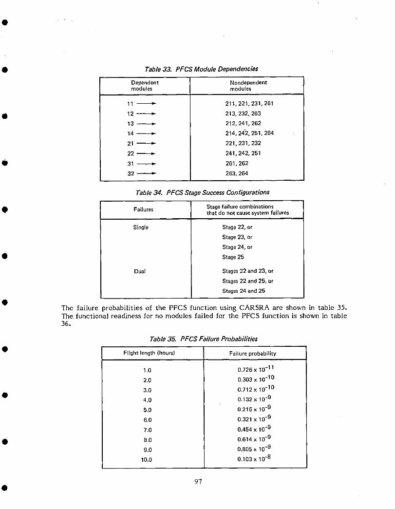
• Table 33. PFCS Module Dependencies
Dependent Nondependentmodules modules
11 _ 211,221,231,261
• 12-------_ 213,232,26313 _ 212,241,262
14-_ 214,242,251,264
21 _ 221,231,232
22------_ 241,242,251
Q 31 _ 261,262
32------_ 263,264
Table 34. PFCS Stage Success Configurations
• Failures Stagefailure combinationsthat do not causesystemfailures
Single Stage22, or
Stage23, or
Stage24, or
• Stage25
Dual Stages22 and23, or
Stages22 and 25, or
Stages24 and25
The failure probabilities of the PFCS function using CARSRA are shown in table 35.The functiona! readiness for no modules failed for the PFCS function is shown in table36.
Table 35. PFCS Failure Probabilities
• Flight length (hours) Failure probability
1.0 0.726 x 10⁻¹¹
2.0 0.303 x 10⁻¹⁰
3.0 0o712x 10-10
• 4.0 0.132 x 10.9
5.0 0.215 x 10⁻⁹
6.0 0.321 x i0 -9
7.0 0.454 x 10⁻⁹
• 8.0 0.614 x 10.99.0 0.805 x 10.9
10.0 0.103 x 10⁻⁸
9?
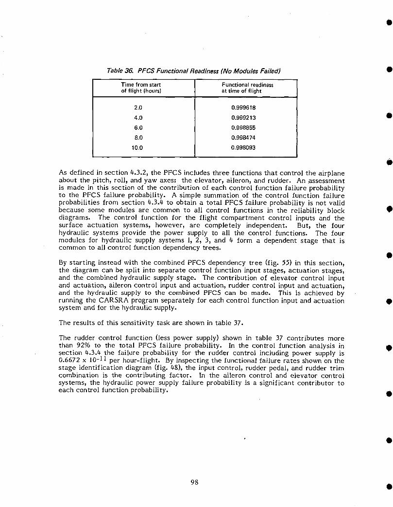
Table 36. PFCS Functional Readiness(No Modules Failed) •
Timefromstart Functionalreadinessof flight (hours) at time of flight
2.0 0.999618
4.0 0.999213 •
6.0 0.998855
8.0 0.998474
10.0 0.998093
O
As defined in section 4.3.2, the PFCS includes three functions that control the airplaneabout the pitch, roll, and yaw axes: the elevator, aileron, and rudder. An assessmentis made in this section of the contribution of each control function failure probabilityto the PFCS failure probability. A simple summation of the control function failureprobabilities from section 4.3.4 to obtain a total PFCS failure probability is not validbecause some modules are common to all control functions in the reliability block •diagrams. The control function for the flight compartment control inputs and thesurface actuation systems, however, are completely independent. But, the fourhydraulic systems provide the power supply to all the control functions. The fourmodules for hydraulic supply systems 1, 2, 3, and 4 form a dependent stage that iscommon to all control function dependency trees.
By starting instead with the combined PFCS dependency tree (fig. 55) in this section,the diagram can be split into separate control function input stages, actuation stages,and the combined hydraulic supply stage. The contribution of elevator control inputand actuation, aileron control input and actuation, rudder control input and actuation,and the hydraulic supply to the combined PFCS can be made. This is achieved byrunning the CARSRA program separately for each control function input and actuation •system and for the hydraulic supply.
The results of this sensitivity task are shown in table 37.
The rudder control function (less power supply) shown in table 37 contributes more
than 92% to the total PFCS failure probability. In the control function analysis in •section 4.3.4 the failure probability for the rudder control including power supply is0.6672 x 10-11 per hour-flight. By inspecting the functional failure rates shown on thestage identification diagram (fig. 48), the input control, rudder pedal, and rudder trimcombination is the contributing factor. In the aileron control and elevator controlsystems, the hydraulic power supply failure probability is a significant contributor to
each control function probability. •
98 •
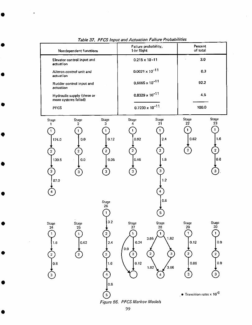
Table 37. PFCS Input and Actuation Failure Probabilities
O Failure probability, PercentNondependent functions 1-hr flight of total
Elevator control input and 0.215 x 10⁻¹¹ 3.0actuation
Aileron control unit and 0.0021 x 10⁻¹¹ 0.3actuation
Rudder control input and 0.6655 x 10 -11 92.2actuation
Hydraulic supply (three or 0.0329 x 10 -11 4.5more systemsfailed)
0PFCS 0.7230 x 10⁻¹¹ 100.0
Stage Stage Stage Stage Stage Stage Stage1 2 3 4 21 22 23
' ?74.05.0 (_0.12 792 ?.4 ?.62 (!6
0.5 .0 0.06 46 8 0.8
, ® ® ® (,) (),.0 1.2
o ® (,_)Stage 0.6
26 _,
0 (.,)Stage Stage 13.2 Stage Stage Stage Stage
• 24 25 _ 27 28 29 30
62 2.4 0.24 12 0.0
. ? .6 0.12 06 0.0
8 _r 1.82 3.66
® q) '_ @0.8
• Transition rates x 10"6
Figure 56. PFCSMarkov Models
Q 99
_.3 MAINTENANCE COST ASSESSMENT •
The total primary flight control system (PFCS) maintenance cost consists of delay andcancellation costs plus direct maintenance cost. The latter includes scheduled andunscheduled line maintenance costs and overhaul shop costs. To determine the totalPFCS maintenance costs9 the available man-hour and delay rate data at the component
level were reviewed. The costs associated with these rates were determined, then the •individual costs were totaled.
Data were extracted from large domestic trunk and international carrier airlines. Anycomparison of maintenance costs between airlines will usually vary because of manyfactors_ including differing maintenance philosophies_ varying route structures, fleetmaturity, geographic location, and accounting methods. Such cost variations cannotbe used to assess airline efficiency or to compare airplane types. •
To help reveal the reasons for cost variations and the methods for cost accumulationand the evolution of the maintenance program_ the maintenance process categoriesand terms are summarized in the following paragraphs.
When any new model of airplane is introduced, the manufacturer, customer airline, andGovernment regulatory agencies convene to produce an initial set of maintenanceguidelines from which each airline designs its maintenance program. In the UnitedStates, the Federal Aviation Administration (FAA) issues an advisory circular (an MRBreport generated by the maintenance review board), which is closely followed by thedomestic airlines and many overseas airlines in developing their individualmaintenance programs. Each program is separately approved by the FAA prior toplacing the new model into service. The individual programs are specifically tailoredto an airline's maintenance philosophy, route structure_ etc. But, they conform closelyto the MRB recommendations for maintenance processes and scheduled time periods.
Although the airlines introduce service on new types of airplanes with scheduledmaintenance frequencies recommended by the MRB, they escalate the frequencies •periodically (upon FAA aproval) as they gain experience with the airplane. At a givenpoint in tim% therefore, an airline that has escalated its maintenance intervals severaltimes over a number of years will experience lower scheduled maintenance cost thanan airline introducing that model of airplane. The escalation process has a profoundeffect on reducing scheduled maintenance costs, and airlines strive for increases in
interval times as experience permits. Interval escalation has little effect on •unscheduled maintenance costs because this is controlled primarily by equipmentreliability.
The term scheduled maintenance, sometimes called preventive or routinemaintenance) can be defined as maintenance performed at intervals to retain an item
in a serviceable condition by actions such as systematic inspection, detection_ •replacement of wear-out items, adjustment, calibration, and cleaning. The scheduledmaintenance cost includes only resources spent for planned maintenance activities.Any resources spent on problems found during planned work become an unscheduledmaintenance cost.
Unscheduled maintenance, sometimes referred to as corrective or nonroutine mainten-anc% is defined as maintenance performed to restore an item to a satisfactory •condition by correcting a known or suspected malfunction or defect.
100
Maintenance processes have evolved over the years to the point where three primaryprocesses are in use on today's jet transport aircraft. They are:
I. Time-controlled (hard time) overhaul-Equipment or structure is overhauled inaccordance with a plan that monitors time histories of individual items. Themonitoring system is used to schedule the removal of items before they exceed a
• specified time limit. Time-controlled overhaul is a preventive maintenanceprocess and is used primarily for structural inspection of the airframe. Oninfrequent occasions it is used to inspect system components that exhibit defined
! wear-out patterns or life limits.
2. On-condition maintenance--Repetitive inspections or tests determine the service-i!0 ability condition of units, systems, or portions of structure (corrective action is
taken when required by item condition). On-condition maintenance is apreventive maintenance process widely used for aircraft components and systemsto reduce the consequences of malfunction by detecting unsatisfactory conditionsor operational degradation prior to complete failure.
3. Condition-monitored maintenance-Data on all specified items in service are• analyzed to determine if technical resources are required. Condition monitoring
is a corrective maintenance process that allows failures to occur and relies uponan analysis of operating experience information to indicate any need for appro-priate action. Action may involve changing the maintenance procedure,redesigning the item, or transferring the item to a different maintenance process.It is a widely used process for items that have no effect on safety and have low
• monetary consequence.
The segregation of items into one of the three maintenance processes is accomplishedby a system known currently as maintenance steering group II (MSG-II). This is alogic-oriented process using a decision tree model to assess the consequences of anaircraft operation failure and, based on the severity of the consequence, to assign the
• item to an appropriate maintenance process. This system is used to develop the initialmaintenance program recommendations prior to certification of the airplane model.Individual airlines will modify the basic recommendations to suit their specific needssubject to Government regulatory agency approval.
A typical breakdown of the direct maintenance cost for a model 7t_7 operator having
• complete in=house maintenance and repair capability is shown in table 38. While somecosts occur for scheduled maintenance on a routine basis, most direct maintenancecosts are categorized as nonroutine or unscheduled.
Scheduled line maintenance for the PFCS includes periodic inspections and checksscheduled as part of the "C" check (see appendix E). Unscheduled line maintenancecan be categorized as maintenance to correct discrepancies found either during
• scheduled maintenance or reported as in-flight malfunctions. Both the scheduled andunscheduled line maintenance are conducted on the airplane. The on-airplane activityin the overhaul shop is mostly confined to structural inspection. The off-airplane shopactivity for the PFCS applies to the components removed for overhaul and repair. Forall PFCS equipment, such maintenance is nearly all unscheduled because of thepredominance of the condition monitoring process.
Maintenance cost is based on a unit of 1,000 flight=hours. Costs are then calculated ona calendar basis by including an annual airplane use of about 3,500 hr for a typical 747operator. Scheduled maintenance costs, line maintenance costs) overhaul shop costs,and delay and cancellation costs are assessed in the following sections.
• IOl
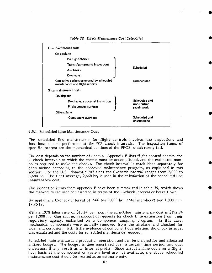
Table 38. Direct Maintenance Cost Categories •
Line maintenance costs
On-airplane
Preflightchecks }
Transit/turnaround inspections •Scheduled
A-checks
C-checks
Correctiveactionsgeneratedbyscheduled Unscheduledmaintenance and flight reports
Shop maintenance costs •
On-airplane
D-checks, structural inspection / Scheduled andnon-routine
Flightcontrolsurfaces repairwork
Off-airplane •Component overhaul Scheduled and
unscheduled
15.3.1 Scheduled Line Maintenance Cost
The scheduled line maintenance for flight controls involves the inspections and •functional checks performed at the "C" check intervals. The inspection items ofspecific interest are the mechanical portions of the PFCS, which rarely fail.
The cost depends on the number of checks. Appendix E lists flight control checks, theC-check intervals at which the checks must be accomplished, and the estimated man-hours required to make the checks. The check interval is established separately for •each airline according to the approved maintenance program, as explained in thissection. For the U.S. domestic 747 fleet the C-check interval ranges from 2,000 to3,600 hr. The fleet average, 2,660 hr, is used in the calculation of the scheduled linemaintenance cost.
The inspection items from appendix E have been summarized in table 39, which shows •the man-hours required per airplane in terms of the C-check interval or hours flown.
By applying a C-check interval of 2.66 per l_000 hr: total man-hours per 1,000 hr =17.75 hr.
With a 1978 labor rate of $10.87 per hour, the scheduled maintenance cost is $192.94 •per 1,000 hr. One airline, in support of requests for check time extensions Irom theirregulatory agency, embarked on a component sampling program. In this case,mechanical components were actually removed Irom the airplane and checked Iorwear and corrosion. With little evidence of component degradation, the check intervalwas escalated and the costs for scheduled maintenance reduced.
Scheduled maintenance is a production operation and can be planned Ior and allocateda fixed budget. The budget is then amortized over a certain time period, and costunderruns, if any, result as an internal profit. Since actual airline costs on a flight-hour basis at the component or system level are not availabl% the above scheduledmaintenance cost should be treated as an estimate only.
102 •
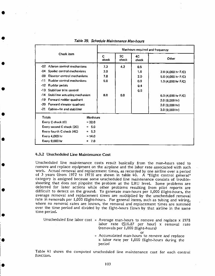
• Table39. ScheduleMaintenanceMan-hours
ManhoursrequiredandfrequencyCheckitem
C 2C 4Ccheck check check Other
-02 Aileroncontrolmechanisms 7.3 4.2 0.5
-04 Spoilercontrolmechanisms 3.9 1.0 2.0 (4,000 hr F/C)
-09 Elevatorcontrolmechanisms 7.8 2.0 5.0 (4,000 hr F/C)-11 Ruddercontrolmechanisms 5.0 0.9 1.0 (4,000 hr F/C)-12 Rudderpedals 0.4
• -13 Stabilizertrim control 0.5
-14 Stabilizeractuatingmechanism 8.0 0.8 6.0 (4,000 hr F/C)-19 Forwardrudderquadrant 2.0 (9,000 hr)
-20 Forwardelevatorquadrant 2.0 (9,000 hr)
! -2! Cables-rfinandstabilizer 3.0 (9,000 hr)0
Totals Manhours
EveryC check(C) ---32.0
EverysecondC check(2C) = 5.0Everyfourth C check(4C) --- 5.3Every4,000 hr = 14.0
• Every9,000 hr = 7.0
0.3.2 Unscheduled Line Maintenance Cost
Unscheduled line maintenance costs result basically from the man-hours used toremove and replace equipment on the airplane and the labor rate associated with such
work. Actual removal and replacement times_ as recorded by one airline over a periodof 3 years (from 1972 to 1975) are shown in table 40. A "flight control general"category is assigned because some unscheduled line maintenance consists of trouble-
shooting that does not pinpoint the problem at the LRU level. Some problems aredeferred for later actions while other problems resulting from pilot reports are
• difficult to detect on the ground. To generate man-hours per 19000 flight-hours_ theaverage removal and replacement times are multiplied by the unscheduled removal
rate in removals per 1,000 flight-hours. For general items_ such as tubing and wiring_where no removal rates are known_ the removal and replacement times are summedover the time period and divided by the fight-hours flown by that airline in the sametime period.
Unscheduled line labor cost = Average man-hours to remove and replace x /978labor rate ($10.87 per hour) x removal rate(removals per I_000 flight-hours)
or
= Accumulated man-hours to remove and replace• x labor rate per 1,000 flight-hours during the
period
Table 41 shows the computed unscheduled line maintenance cost for each controlfunction.
• 103
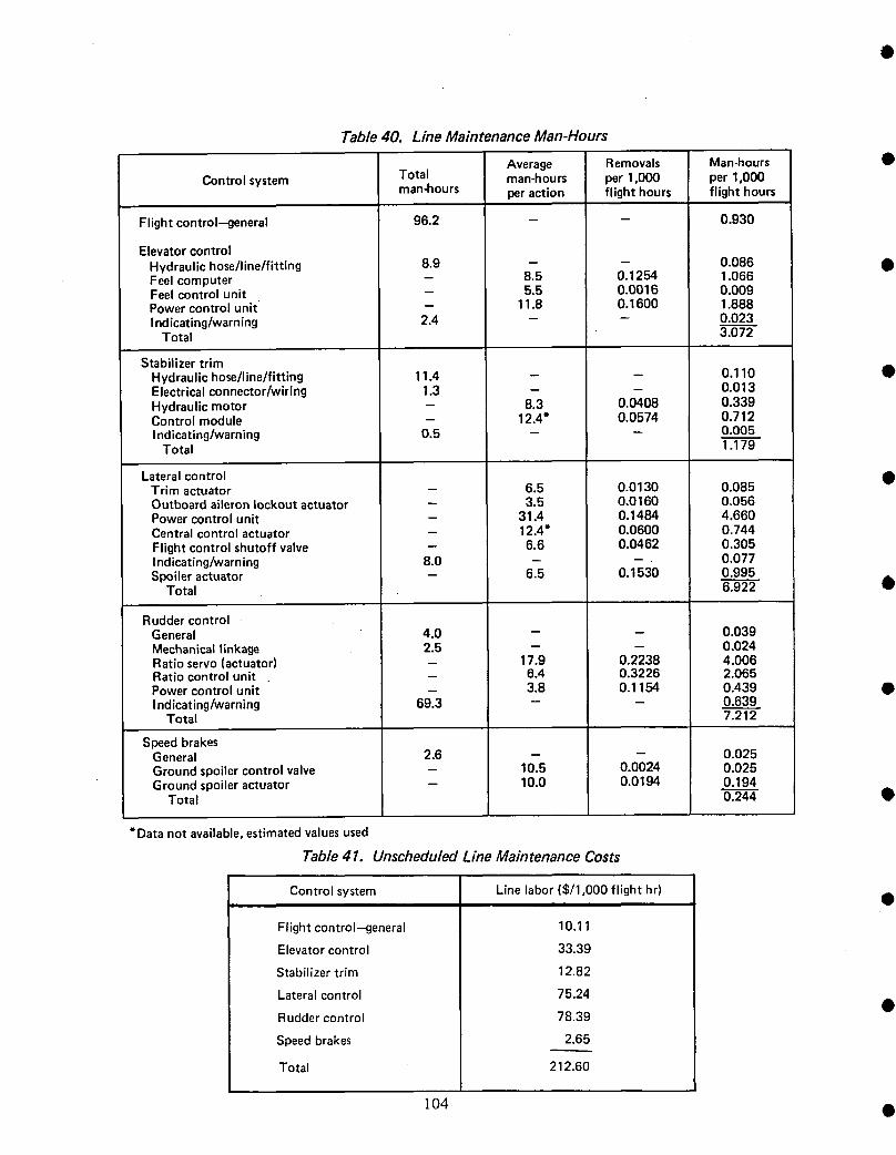
Table 40. Line Maintenance Man-Hours
Average Removals Man-hours •Controlsystem Total man-hours per 1,000 per1,000
man-hours per action flight hours flight hours
Flight control-general 96.2 - - 0.930
ElevatorcontrolHydraulichose/line/fitting 8.9 -- -- 0.086 •Feelcomputer -- 8.5 0.1254 1.066Feelcontrolunit - 5.5 0.0016 0.009Powercontrolunit -- 11.8 0.1600 1.888Indicating/warning 2.4 - - 0.023
Total 3.072-
StabilizertrimHydraulichose/line/fitting 11.4 - - 0.110 •Electricalconnector/wiring 1.3 - - 0.013Hydraulicmotor - 8.3 0.0408 0.339Controlmodule - 12.4" 0.0574 0.712| ndicating/warning 0.5 -- -- 0.005
Total 1.179
Lateralcontrol •Trim actuator -- 6.5 0.0130 0.085Outboardaileronlockoutactuator -- 3.5 0,0160 0,056Powercontrolunit -- 31.4 0.1484 4.660Centralcontrolactuator - 12.4" 0.0600 0.744Flightcontrolshutoffvalve - 6.6 0.0462 0,305Indicating/warning 8.0 - - 0.077Spoileractuator - 6.5 0.1530 0,995
Total 6.922 •
RuddercontrolGeneral 4.0 - - 0,039Mechanicallinkage 2.5 -- -- 0,024Ratioservo(actuator) -- 17.9 0.2238 4.006Ratiocontrolunit _ 6.4 0.3226 2.065Powercontrolunit -- 3.8 0.1154 0.439 •Indicating/warning 69.3 -- -- 0.639
Total 7.212
SpeedbrakesGeneral 2.6 - -- 0.025Groundspoilercontrolvalve - 10.5 0.0024 0.025Groundspoileractuator - 10.0 0.0194 0.194
Total 0,244 •
* Data notavailable,estimatedvaluesused
Table 41. Unscheduled Line Maintenance Costs
Control system Line labor ($/1,000 flight hr) •
Flightcontrol-general 10.11
Elevatorcontrol 33.39
Stabilizertrim 12.82
Lateralcontrol 75.24
Ruddercontrol 78.39 •
Speedbrakes 2.65
Total 212.60
104 •
• 4.3.3 Overhaul Shop Maintenance Cost
Components removed from the airplane are sent to the main base overhaul shop whereinitial testing is carried out, when required, and parts are then overhauled. The twosignificant cost elements are labor to overhaul and test the components and materialsto repair and refurbish them.
The cost accounting associated with components that move through the overhaul shopis not specifically accumulated by airplane type or airplane system. The shops arearranged by the ability to handle similar types of equipment such as hydraulics orelectrical. Thus, flight control components being overhauled most likely will be fromdifferent types of airplanes in the fleet and spread through more than one overhaul
• shop.
Some airlines,however, do keep trackof components for costpurposesat the airlinestock number level. The stock number is usuallyidentifiedwith a particular
component used on a particularairplane.
• Data for overhaul shop maintenance cost were obtained from one airline thatidentified cost with particular 747 flight control components. Costs for both labor andmaterial were accumulated over a 7-month period. In order to equate these costs to a
flight-hour basis, the flight-hours flown during the same period of time were used.
The 197g-dollar shop costs are shown in table 42, which also shows costs obtained for
• some components from two other airline sources. In these two cases, labor man-hoursper shop visit and material cost (for 1977) per shop visit were available. The costs per1,000 flight-hours were generated as follows:
o Shop labor = Labor man-hours per visit x 1978 labor rate ($10.g7 perhour) x removal rate (removals per 1,000 flight-hours)
• o Shop material = Material cost per visit x removal rate (removals per 1,000flight-hours) x inflation factor (1977-1978 = 1.086)
An attempt was made to identify costs of overhauling flight control cables and pulleys.Since these items will most likely be deleted in future flight control designs, their costis of special interest. The airline costs for cables and pulleys are available only at a
• whole-fleet level, in this case comprising six different airplane types. These costswere then factored by the ratio of 747 airplanes to the fleet. This may not be anaccurate assessment, but should reflect cable and pulley costs in relation to other
flight control component costs.
The costs between airlines are expected to vary because accurate costs are difficult to• assess because of the low overhaul rate of the mechanical and hydraulic components.
For example, for an actuator with a removal rate of 100 per 106 flight-hours and afleet of l0 airplanes flying 30,000 hr per year, the overhaul shop will be repairingthree actuators in that year. Electronic equipment, however, has a much higher flowrate through the overhaul shop and the associated costs can be assessed moreaccurately.
• 105

Table 42. Overhaul Shop Maintenance Costs
Shoplaborcost Shopmaterialscost •Controlsystem ($/1,000 flighthour) ($/!,000 flight hour) Total
General(pulleys,cables) 4.84 13.23 18.07
ElevatorcontrolFeelactuator 1.80 (8.99) 2.26 (0.0)Feelcomputer 10.20 (80.83) 6.24 (123.66) •Powercontrolunit 49.81 (221.17) 153.86 (270.35)
Total 61.81- _ 224.17
StabilizertrimDrivemechanism 5.70 0Controlmodule 11.67 105.36
Total 17.37 105.36 122,73
LateralcontrolTrim actuator 3.31 (0.93) 0 (0.08)Flightcontrolshutoffvalve 17.11 (2.59) 11.62 (0,0)
Centralcontrolactuator 45.61 274.92Outboardaileronlockoutactuator 6.30 (0.28) .56 (0.0)Aileronprogrammer 11.58 3.01Inboardaileronpowercontrolunit 23.41 (53.39) 195.74 (213.30) •Outboardaileronpowercontrolunit 10.20 350.80Spoilerdifferential(mixer) 11.40 6.31Spoileractuator 4.80 (7.82) 10.30 (0.0)
Total 133.72 853.26 986.98
Ruddercontrol
Powercontrolunit 90.31 (101.86) 618.01 (1335.46) •Rudderratioservoactuator 14.10 (18.68) 2.55 (0.0)Rudderratio controlunit 26.41 (12.73) 56.66 (23.49)
Total 130.82 677.22 808.04
SpeedbrakesSequencemechanism 2.10 19.85Groundspoileractuator 15.31 5.31
Total 17.4--'_1- 25.16 42.57 •
NOTE: Figuresin parenthesesarecostsfrom two otherairlinesources
#.3.# Delay and Cancellation Costs
The mechanical delays and cancellations of the 747 fleet during a number of revenue •flights can be shown as the percentage of flights departing on time (schedulereliability). This reliability is a useful measure of the airplane's mechancial operatingperformance. Details of delays and cancellations are readily available in the airlinereports for assessing performance.
The written accounts of delays and cancellations are charged, where possible, to •equipment at the line-replaceable unit level. A delay can be charged to a componentwhether it is replaced or not. Troubleshooting that delays a flight departure mayresult in equipment being tagged inoperative if it is not dispatch-critical. In this cas%the problem will be deferred to a time allotted for scheduled maintenance. In some
cases_ a pilot report will initiate a maintenance action but fail to pinpoint theproblem. If a delay results_ it is charged to a general category within the airplanesystem involved. •
The delays and cancellations for the PFCS have been tabulated at the component leveland general subject level (table 43). There were 23%518 revenue departures for the747 fleet during the reporting period of 1977.
106 •
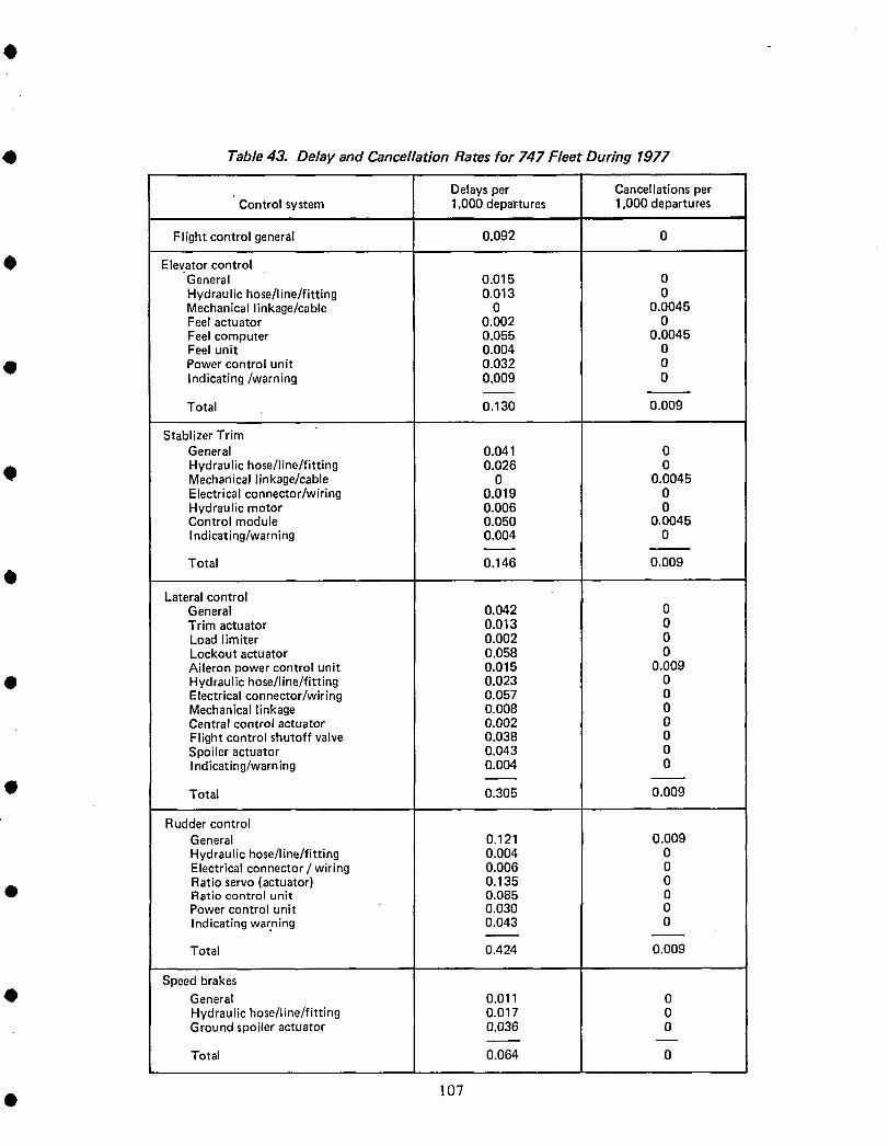
0 Table 43. Delay and Cancellation Rates for 747 Fleet During 1977
Delays per Cancellations per' Control system 1,000 departures 1,000 departures
Flight control general 0.092 0
• Elevator controlGeneral 0.015 0Hydraulic hose/line/fitting 0.013 0Mechanical linkage/cable 0 0.0045Feel actuator 0.002 0Feel computer 0.055 0.0046Feel unit 0.004 0
• Power control unit 0.032 0Indicating/warning 0.009 0
Tot al 0.130 0.009
Stablizer TrimGeneral 0.041 0Hydraulic hose/line/fitting 0.026 0
• Mechanical linkage/cable 0 0.0045Electrical connector/wiring 0.019 0Hydraulic motor 0.006 0Control module 0.050 0.0045Indicating/warning 0.004 0
Total 0.146 0.009
Lateral controlGeneral 0.042 0Trim actuator 0.013 0Load limiter 0.002 0Lockout actuator 0.058 0Aileron power control unit 0.015 0.000
• Hydraulic hose/line/fitting 0.023 0Electrical connector/wiring 0.057 0Mechanical linkage 0.008 0Central control actuator 0.002 0Flight control shutoff valve 0.038 0Spoiler actuator 0.043 0Indicating/warning 0.004 0
• Total 0.305 0.009
Rudder controlGeneral 0.121 0.009Hydraulic hose/line/fitting 0.004 0Electrical connector / wiring 0.006 0Ratio servo (actuator) 0.135 0
• Ratio control unit 0.085 0Power control unit 0.030 0
Indicating warning 0.043 0
Total 0.424 0.009
Speed brakes• General 0.011 0
Hydraulic hose/line/fitting 0.017 0Ground spoiler actuator 0.036 0
Total 0.064 0
• 107
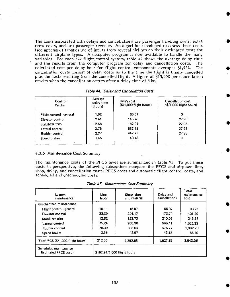
The costs associated with delays and cancellations are passenger handling costs, extra •crew costs, and lost passenger revenue. An algorithm developed to assess these costs.(see appendix' F) makes use of inputs from several airlines on their estimated costs fordifferent airplane types. A computer program is now available to handle the manyvariables. For each 7ti.7 flight, control system, table 44 shows the average delay timeand the results from the computer program for delay and cancellation costs. Thecalculated cost per delay-hour for flight control components averages $1,954. The •cancellation costs consist of delay costs up to the time the flight is finally cancelledplus the costs resulting from the cancelled flight. A figure of $13,058 per cancellationres,alts when the cancellation occurs after a delay time of 5 hr.
Table 44. Delay and Cancellation Costs
AverageControl delaytime Delaycost Cancellationcostsystem (hours) ($/1,000flighthours) ($/1,000flighthours)
Flightcontrol--general 1.52 65.07 0Elevatorcontrol 2.41 145.76 27.98Stabilizertrim 2.68 182.04 27.98Lateralcontrol 3.75 532.13 27.98Ruddercontrol 2.27 447.79 27.98Speedbrakes 1.45 43.18 0
_.3.5 Maintenance Cost Summary O
The maintenance costs at the PFCS level are summarized in table 45. To put thesecosts in perspective, the following subsections compare the PFCS and airplane line,shop, delay, and cancellation costs; PFCS costs and automatic flight control costs; and
scheduled and unscheduled costs. •
Table 45. Maintenance Cost Summary
TotalSystem Line Shoplabor Delayand maintenancemaintenance labor andmaterial cancellations cost
UnscheduledmaintenanceFlightcontrol-general 10.11 18.07 65.07 93.25Elevatorcontrol 33.39 224.17 173.74 431.30Stabilizertrim 12.82 122.73 210.02 345.57Lateralcontrol 75.24 986.98 560.11 1,622.33Ruddercontrol 78.39 808.04 475.77 1,362.20Speedbrakes 2.65 42.57 43.18 88.40 •
TotalFCS($/1,000flighthours) 212.60 2,202.56 1,527.89 3,943.05
Scheduled maintenanceEstimatedPFCScost= $192.94/1,000flighthours
108 •
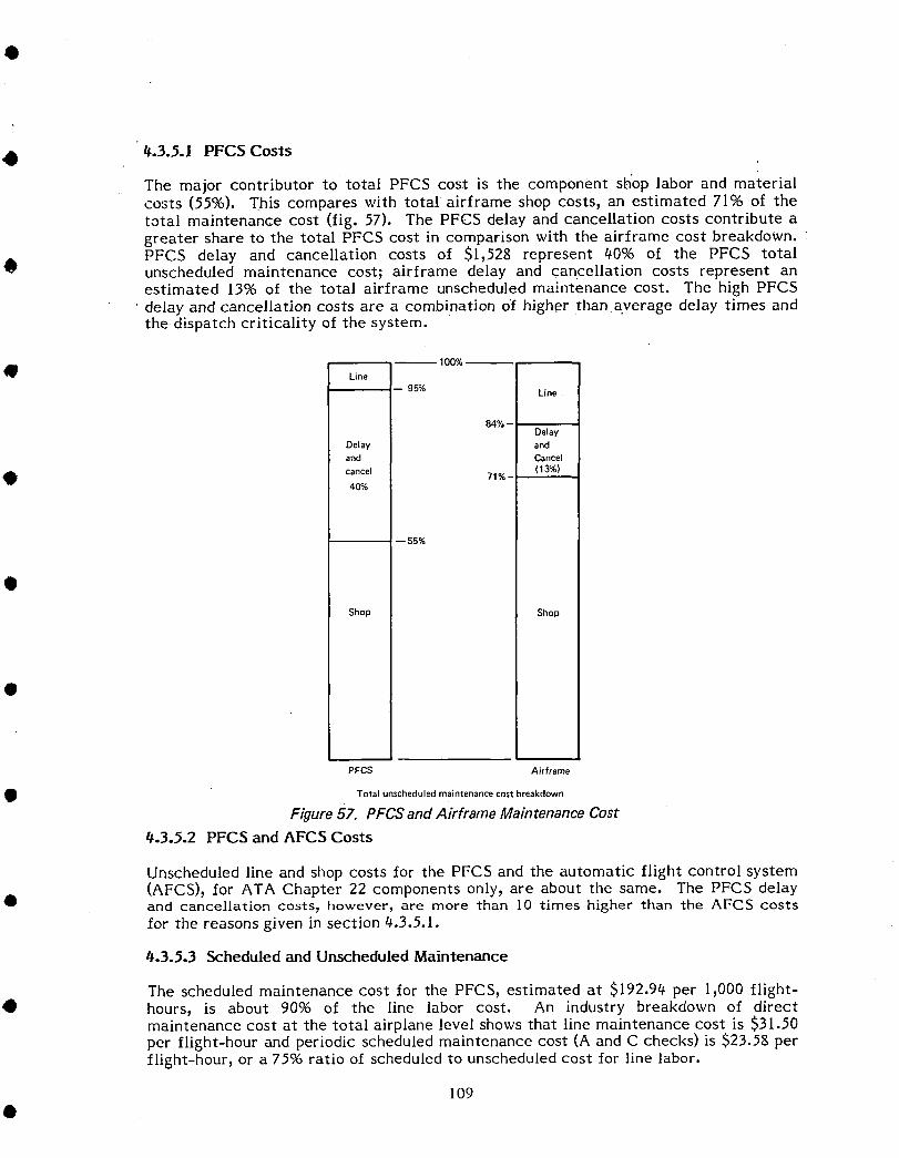
#.3.5.1 PFCS Costs
The major contributor to total PFCS cost is the component sh_oplabor and materialcosts (5596). This compares with total airframe shop costs, an estimated 71% of thetotal maintenance cost (fig. 57). The PFCS delay and cancellation costs contribute agreater share to the total PFCS cost in comparison with the airframe cost breakdown.PFCS delay and cancellation costs of $1,528 represent 40% of the PFCS total
• unscheduled maintenance cost; airframe delay and cancellation costs represent anestimated 13% of the total airframe unscheduled maintenance cost. The high PFCS
• delay and cancellation costs are a combination o'f higher than average delay times andthe dispatch criticality of the system.
100%
• Line
-- 95% Line
84% --Delay
Delay andand Cancel
(13%)cancel 71% -40%
-- 55%
Shop Shop
PFCS Airframe
Total unscheduled maintenance cost breakdown
Figure57. PFCSandAirframe MaintenanceCostt_.3.5.2 PFCS and AFCS Costs
Unscheduled line and shop costs for the PFCS and the automatic flight control system(AFCS), for ATA Chapter 22 components only, are about the same. The PFCS delay
• and cancellation costs, however, are more than 10 times higher than the AFCS costs
for the reasons given in section t_.3.5.1.
#.3.5.3 Scheduled and Unscheduled Maintenance
The scheduled maintenance cost for the PFCS, estimated at $192.94 per 1,000 flight-• hours, is about 90% of the line labor cost. An industry breakdown of direct
maintenance cost at the total airplane level shows that line maintenance cost is $31.50per flight-hour and periodic scheduled maintenance cost (A and C checks) is $23.58 perflight-hour, or a 75% ratio of scheduled to unscheduled cost for line labor.
109
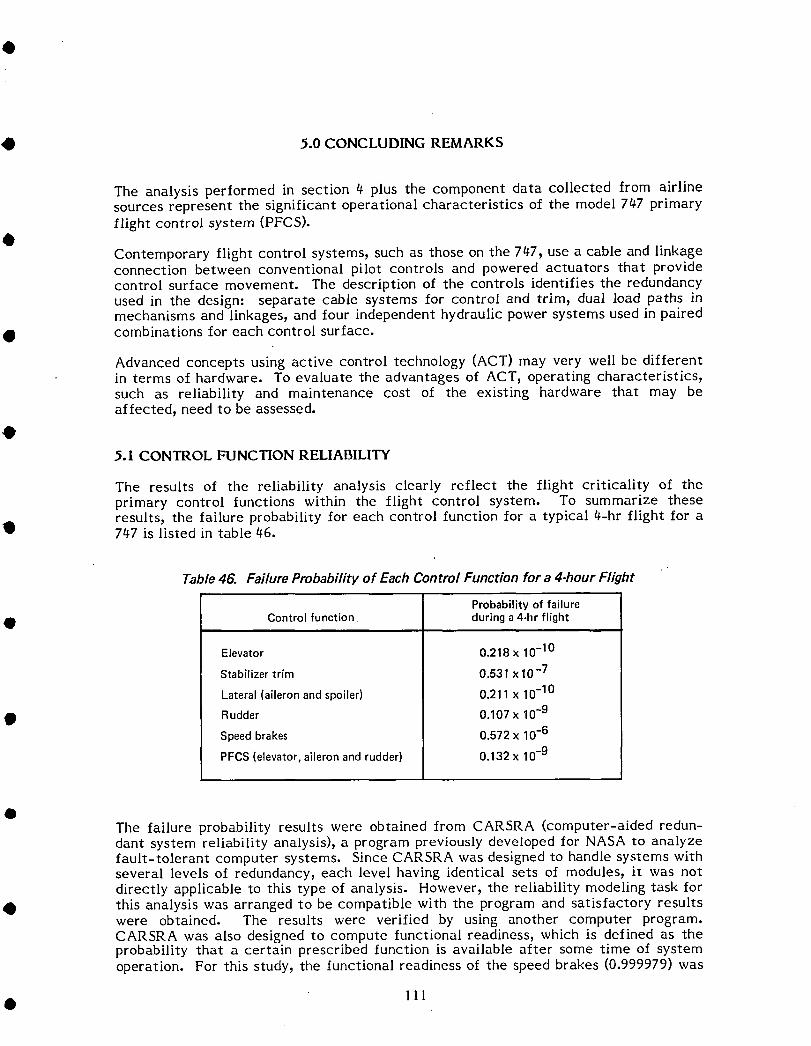
O 5.0 CONCLUDING REMARKS
The analysis performed in section 4 plus the component data collected from airlinesources represent the significant operational characteristics of the model 747 primaryflight control system (PFCS).
Contemporary flight control systems, such as those on the 747, use a cable and linkageconnection between conventional pilot controls and powered actuators that providecontrol surface movement. The description of the controls identifies the redundancyused in the design: separate cable systems for control and trim, dual load paths inmechanisms and linkages, and four independent hydraulic power systems used in paired
• combinations for each control surface.
Advanced concepts using active control technology (ACT) may very well be differentin terms of hardware. To evaluate the advantages of ACT, operating characteristics,such as reliability and maintenance cost of the existing hardware that may beaffected, need to be assessed.
@5.1 CONTROL FUNCTION RELIABILITY
The results of the reliability analysis clearly reflect the flight criticality of theprimary control functions within the flight control system. To summarize theseresults, the failure probability for each control function for a typical 4-hr flight for a
• 747 is listed in table 46.
Table 46. Failure Probability of Each Control Function for a 4ohour Flight
Probability of failure
0 Control function during a 4-hr flight
Elevator 0.218 x 10⁻¹⁰
Stabilizer trim 0.531 x 10⁻⁷
Lateral(aileronandspoiler) 0.211x 10⁻¹⁰
0 Rudder 0.107x 10⁻⁹Speedbrakes 0.572x 10⁻⁶
PFCS(elevator,aileronandrudder) 0.132x 10⁻⁹
@The failure probability results were obtained from CARSRA (computer-aided redun-dant system reliability analysis), a program previously developed for NASA to analyzefault-tolerant computer systems. Since CARSRA was designed to handle systems withseveral levels of redundancy, each level having identical sets of modules, it was notdirectly applicable to this type of analysis. However, the reliability modeling task for
• this analysis was arranged to be compatible with the program and satisfactory resultswere obtained. The results were verified by using another computer program.CARSRA was also designed to compute functional readiness, which is defined as theprobability that a certain prescribed function is available after some time of systemoperation. For this study, the functional readiness of the speed brakes (0.999979) was
• 111
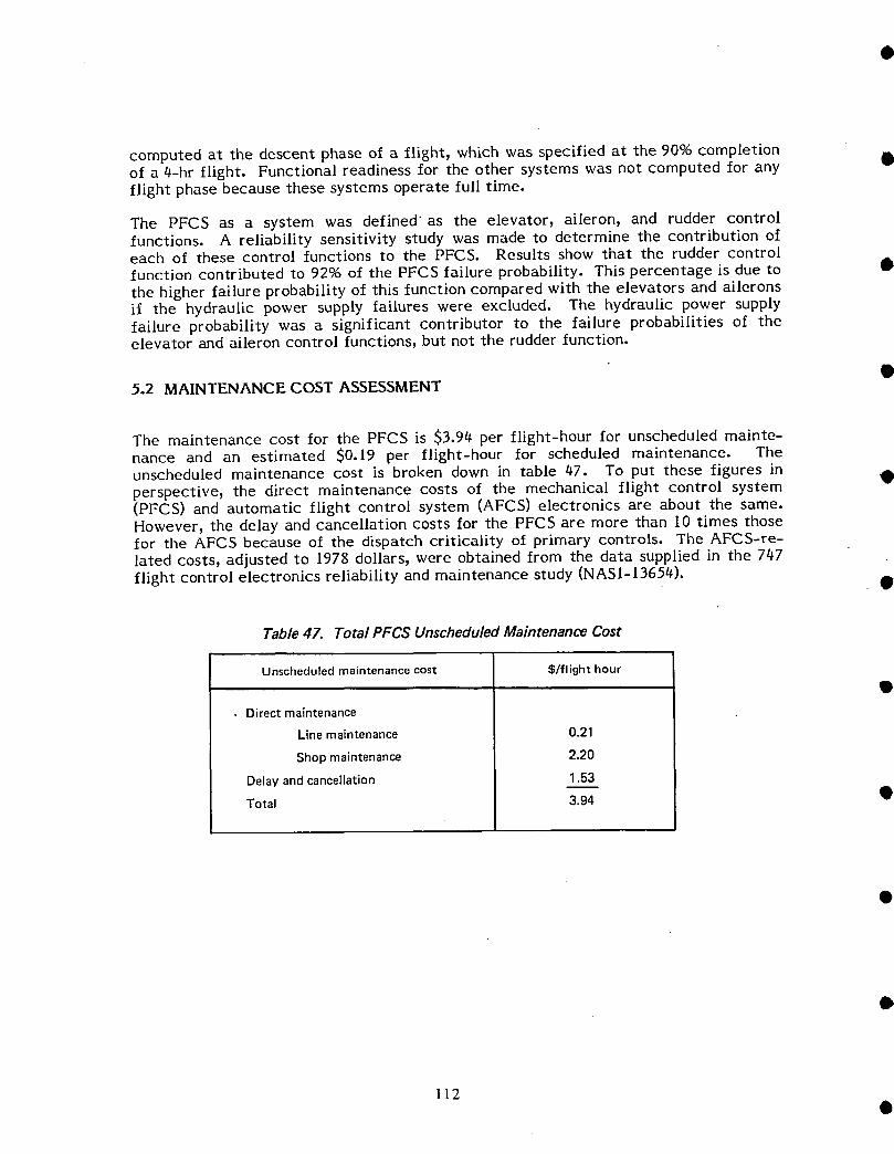
computed at the descent phase of a flight, which was specilied at the 90% completion •of a 4-hr flight. Functional readiness for the other systems was not computed for anyflight phase because these systems operate full time.
The PFCS as a system was defined as the elevator, aileron, and rudder controlfunctions. A reliability sensitivity study was made to determine the contribution ofeach of these control functions to the PFCS. Results show that the rudder controlfunction contributed to 92°,6 of the PFCS failure probability. This percentage is due to •the higher failure probability of this function compared with the elevators and aileronsif the hydraulic power supply failures were excluded. The hydraulic power supplyfailure probability was a significant contributor to the failure probabilities of theelevator and aileron control functions, but not the rudder function.
5.2 MAINTENANCE COST ASSESSMENT
The maintenance cost for the PFCS is $3.94 per flight-hour for unscheduled mainte-nance and an estimated $0.19 per flight-hour for scheduled maintenance. The
unscheduled maintenance cost is broken down in table 47. To put these figures in •perspective, the direct maintenance costs of the mechanical flight control system(PFCS) and automatic flight control system (AFCS) electronics are about the same.However, the delay and cancellation costs for the PFCS are more than I0 times thosefor the AFCS because of the dispatch criticality of primary controls. The AFCS-re-lated costs, adjusted to 1978 dollars, were obtained from the data supplied in the 747
flight control electronics reliability and maintenance study (NAS1-13654). •
Table 47. Total PFCS Unscheduled Maintenance Cost
Unscheduled maintenance cost S/flight hour
• Direct maintenance
Line maintenance 0.21
Shop maintenance 2.20
Delay and cancellation 1.53
Total 3.94 Q
112Q
• 6.0 REFERENCES
I. NASA CR-105024, Airborne Advanced Reconfigurable Computer System (ARCS),contract NAS1-13654, August 1976
2. Welker, E.L. and M. Lipow, "Estimating the exponential failure rate from datawith no failure events," Proceedings of 1974 Annual Reliability and Maintain-ability Symposium
O3. MIL-HDBK-217B, Military Standardization Handbook. Reliability Prediction of
Electronic Equipment, September 1974
• 4. NASA CR-145271, Flight Control Electronics Reliability/Maintenance Study,contract NAS1-13654, December 1977
113

OAPPENDIXA
CARSRA PROGRAMDESCRIPTIONAND USERSGUIDE
CARSRA is a FORTRAN program specifically developed during the ARCS contract
(NA51-13654) and the sections on the program description and the guide for setting upthe input for the computer are included in this appendix.B
• A-1

CARSRA, A RELIABILITY ESTIMATION TOOL.FOR REDUNDANT SYSTEMS O
1. 0 PROGRAM DESCRIPTION
1. 1 Introduction
CARSRA (Computer AicbdRedundant System Reliability Analysis) is a FORTRAN programe
which is designed to facilitate the reliability assessment task for fault tolerant recon-
figurable systems. It is capable of taking into account influences from transient faults
and will model a wide range of redundancy management strategies.
Many previously developed reliability estimation tools are based on success paths tabu-
lation. Examples are the TASRA program developed by Battelle Columbus Laboratories
(reference 1) and the ARMM program described in re_erenee 2. One disadvantage of
the success path tabulation approach is the very large number of success paths in a •
highly redundant system. Another perhaps more significant disadvantage with the above
mentioned programs is their inability to model transient fault and failure coverage effects
where the latter parameter reflects the probability of detecting, isolating and recover-
ing from a failure. •
Recently, see for example references 3 and 4, Markov modeling has been utilized to
model the effect of failure coverage. The Markov model has the advantage of offering
high flexibility which makes it possible to take into account most factors of interest
including fault transients, failure coverage and the possibility of spares or maintenance
a e t i o n s. However, a basic disadvantage with the direct Markov model approach is I
the very large number of Markov states required to model a system with (many) 11internalsignalconsolidation(voting)nodes, i
The most significant feature of the CARSRA program is the concept of partitioning the
system into smaller entities, each of which may be treated by a Markov model of Q
lower dimension. This preserves the Markov model flexibility, avoiding the problem
of an exorbitant number of Markov states.
Another significant feature of CARSRA is the ability to assess Functional Readiness •
as well as system failure probability, The concept of Functional Readiness is of con-
siderable significance for a mission containing a critical subtask which will eitherI
A-2 e!i

be performed, or not performed, depending on the operational redundancy level at
• the time of demand. An example is an aircraft automatic landing function for which a
certain level of hardware redundancy is required before a landing may be initialized
in poor visibility weather conditions.
• 1.2 Definition of Terms
A number of special terms are defined which will be used in the following.
A module is the smallest functional entity treated by the program.. It has a Poisson
type failure distribution with an a priori know failure rate.
A _ is a set of identical redundant modules. Vot_ or Signal Consolidation is often
• performed on the output signals from the modules in a stage. There are however stages
without output voting. TM....._R_Rstands for Triple M__odularRedundancy and is associated with
maiqrity voting on the module outputs of a stage such that at least two out of three mod-
ules have to operate for the stage to survive.
A channel is a particular minimal set of modules capable of performing the system
function in a non-redundant configuration.
• 1.3 The CARSRA Approach
The system is conceptually partitioned into stages, for example each sensor type in
a flight controls system will constitute a stage as will the processors and each servo function.
• The operational status of each stage is modeled by a finite order Mai-kov process in
which each state corresponds to a particular redundancy state. An example is shown
in Figure 1.
• The transition rates ),ij in the figure are assumed constant, i.e., not time varying
and CARSRA will handle up to ten states per stage.
The operational status of a module in a particular stage may or may not depend on
modules in other stages being operational. A module which when failed will cause
loss of function of another module in a different stage will be called a "dependency" module
and the corresponding stage a -dependency stage".
• A-3

FIGUREi EXAMPLEOF STAGE MARKOV MODEL"
NO FAILURE
ONE FAILURELATENT FAILURE
> Z35 X26.!
TWOFAILURES
THREE-FAILURES
DETECTED UNDETECTED
EXAMPLE= )'34= 2ApA.34,+ 2XT_34• ,
A..= PERMANENTRATE RATIO
_..= LEAKAGE
• • • • • • • • • • •
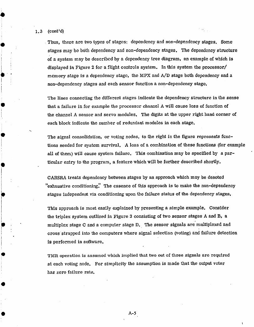
1.3 (cont'd)
• Thus, there are two types of stages: dependency and non-dependency stages. Some
stages may be both dependency and non-dependency stages. The dependency structure
i of a system may be described by a dependency tree diagram, an example of which isdisplayed in Figure 2 for a flight controls system. In this system the processor/
memory stage is a dependency stage, the MPX and A/D stage both dependency and a
non-dependency stages and each sensor function a non-dependency stage.
The lines connecting the different stages indicate the dependency structure in the sense
B that a failure in for example the processor channel A will cause loss of function of
'_ the channel A sensor and servo modules. The digits at the upper right hand corner ofi
i each block indicate the number of redundant modules in each stage.
Q The signal consolidation, or voting nodes, to the right in the figure represents func-
tions needed for system survival. A loss of a combination of these functions (for examplei
i all of them) will cause system failure. This combination may be specified by a par-
ticular entry to the program, a feature which will be further described shortly.0
CARSRA treats dependency between stages by an approach which may be denoted
"exhaustive " " " "condltlomng. The essence of this approach is to make the non-dependency
stages independent via conditioning upon the failure status of the dependency stages.
This approach is most easily explained by presenting a simple example. Consider
the triplex system outlined in Figure 3 consisting of two sensor stages A and B, a
• multiplex stage C and a computer stage D. The sensor signals are" multiplexed and
cross strapped into the computers where signal selection (voting) and failure detection
is performed in software.
• TMR operation is assumed which implied that two out of three signals are required
at each voting node. For simplicity the assumption is made that the output voter
has zero failure rate.
O A-5\
I
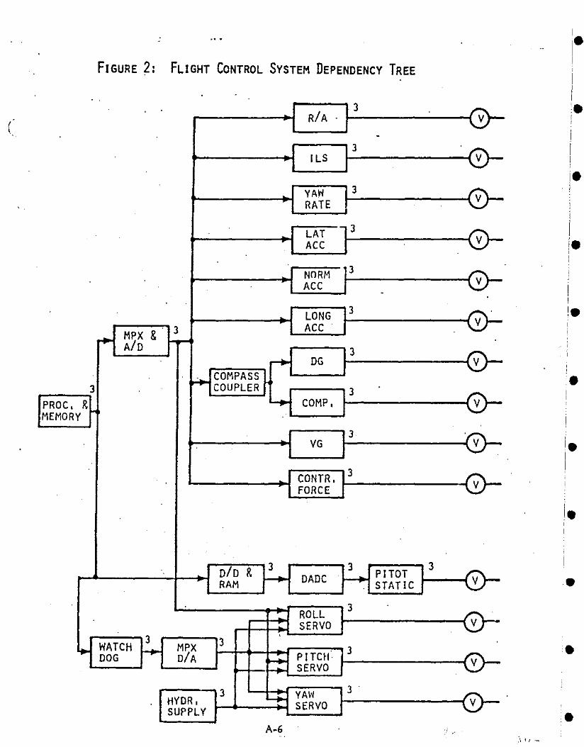
FIGURE 2: FLIGHT CONTROL SYSTEM DEPENDENCY TREE
..3
RIA V
-3
po ILS V
3.. YAW VRATE
.- 3LATr- ACC V
3NORt1ACC V
.
3LONG.. VACC& 3
r+- MPX~-AID 3
~ DG VCOMPASS
~3 COUPLER 3~ COMP. VPROC. R
MEMORY ~
3VG V
3CONTR.FORCE V
,
DID & 3 3 PITOT3
.. DADe .. VRAM --- ..... STATIC
3.. ROLLV.. SERVO
3.
WATCH 3~ r-.. MPX
PITCH" 3DOG DIA ~ VSERVO
3 .3 l-+- YA\~
VHYDR. SERVOSUPPLYA-6
,'I i I ._-
•
•
•
•
•
•
•
•
•
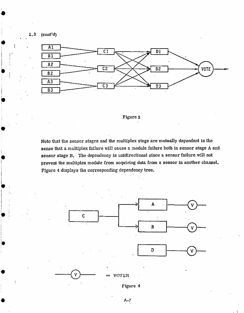
I.3 (cont'd)
!! ! A1 cl , D1I B1
C2 - _ D2I B2
I' A3 _ _:_:_ C3IB3 D3
I
Figure 3
e
Note that the sensor stages and the multiplex stage are mutually dependent in the
i sense that a multiplex failure will cause a module failure both in sensor stage A and
0 sensor stage B. The dependency is unidirectional since a sensor failure will notprevent the multiplex module from acquiring data from a sensor in another channel.
Figure 4 displays the corresponding dependency tree.
' l c I
e
Figure 4
• A-7
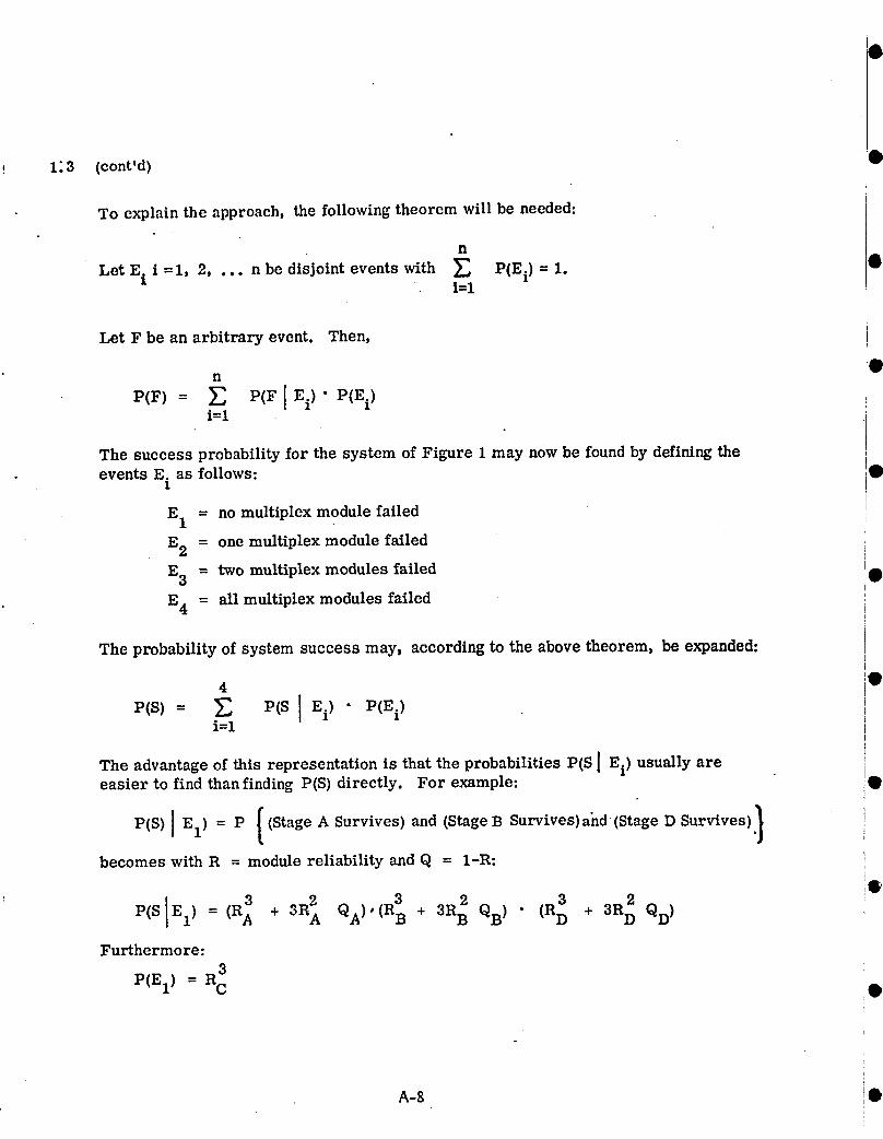
! 1:3 (cont'd)
To explain the approach, the following theorem will be needed:
n
Let Ei i =1, 2, ... n be disjoint events with _ P(Ei) = 1.i=l
Let F be an arbitrarYnevent. Then, •
P(F)-- _ P(FIEi) "P(Ei)i=l
The success probability for the system of Figure 1 may now be found by defining theevents E. as follows:
1
E1 = no multiplex module failed
E2 = one multiplex module failed i
E3 = two multiplex modules failed •
E4 -- all multiplex modules failed
The probability of system success may, according to the above theorem, be expanded:
4 •
PCs)= _ p(s I Ei) • P(_i)i=l
The advantage of this representation is that the probabilities P(S ] Ei) usually are •easier to find than finding P(S) directly. For example:
P(S) l El)_ P { (Stage A Survives) and (Stage B Survives) and (Stage n Survives) 1 I
becomes with R = module reliability and Q = l-R: i
i•
P(SIE1) = (RA + 3RA QA)'(R_ + 3R2 QB ) • (RD8 + 3R2 QD )
Furthermore:3
P(EI)= RC i•
A-8 !o

1.3 (cont'd); . |
The next term in the expression contains the factor P(S IE_), i.e., the probability of( system survival given that one multiplex module is failed. - In-this case both of the
remaining modules in sensor stages A and B have to survive for system survival:i.
i P(SIEg+) =R A • RB • (R + 3R QD)O.
' P(E2)= 3R2 QC
FinallyP(S]E3) = P(S]E4) = 0
• Summarizing, the system reliability becomes:
3 +
• + RA RB QD) QC;l
Note that this expression differs from what is obtained if the stages are assumedindependent:
Q ,,-:-++++- P(SIND) = (R3 + 3R2QA) 'R3 + 3R2 QB) (Rc + 3R2 + 3R2 QC ) "
i . ,++ ,+o,;l "As was mentioned above, the voted (or signal consolidated) outputs from the non-
', dependency stages constitute the functions required for systems survival. There
i are,.however, situations where these functions themselves may be redundant, for
• example the redun_lancy between aileron and spoiler control surfaces of certain air-
crafts. CARSRA will model this situation by accepting a success event tabulation cover-
ing all, non-dependency stage combinations equivalent to system success.
$ Summarizing, the computation is performed in three different steps: Markov model-
ing for eachstage, treating dependencies between stages via exhaustive conditioning
and specifying the functions needed for success by success configuration tabulation.
1.4 The Functional Readiness Feature
Fault tolerant systems will continue to perform their functions even after experienc-
(' ing one or several module failures. With this basic feature it will be of interest to
• be able to assess the probability of experiencing'a certain redundancy degradation
within a prescribed time interval and furthermore to be able to assess the system _A-9

failure probabi!ity given that a certain degradation has taken place. This informa-
tion could be used to establish Functional Readiness Criteria, i.e., the system failure
states that will not cause deferment of a particularly critical phase of a mission, for
example the landing a manned spacecraft on the moon or the previously mentioned case
of automatic landing of a passenger transport in low'visibility weather conditions.
CARSRA accepts a selected Functional Readiness Criterion specifying the combination
of modules which could be failed and computes the probability of having any of these
modules failed as a function of time. It also computes the system failure given a
Functional Readiness Criterion as a function of time in separately specified time frame.
Two different system failure modes may be specified, e.g., detected or undetected
system failure. ,.
The following relations are used. Let PFR(t 1) , i=l, 2, ... N denote the probabilities •associated with the different specified Functional Readiness configurations at a time t1
and let PFP i (t2) be the conditional probability of a certain failure mode at an exposure
time t2 given Functional Readiness configuration i :
CARSRA then computes: N •
PFR = Functional Readiness = iE=l PFRi(t 1)
PFP = Failure Probability = r. PFP i (L2) x PFR i (tl) • PFR -1i=l
In addition to the above mentioned features, two levels of computational accuracy may
be specified. The resulting computational roundoff errors are indicated in the computer
printout.
1.5 CARSRA Program Structure •
In this section, the structure of the program will be described in enough detail to
provide a basic understanding of the operation.
The program is designed using a top-down approach with each subtask carried out in a •
separate subroutine. The overall structure is shown in Figure 5.
MAIN is the main program and each of the other blocks represents subroutines with a
higher order subroutine calling a lower order routine as indicated by the lines connect-
ing the different blocks. The subroutine FAILPR will, for example, call the subroutine •
SETETY, STRIP, EQUAL, PRINTZ, INDFP and DEPFP. °
The operation of each of the subroutines and their interplay will next be described.
A-IO •

• --.----------- ...•-- ---------- .n-- .~-------u _... __ ._ _.._. . ...._..... .... .. ._ .._. .•__m. ._. • •_ ...._. __• • __ mum ••__ •
MAIN
READ IN I INITYZ ICOMPUTEI OUTPUT
»-I........
FORMT
SETETY
AVAIL
EQUAL
FAILPR
PRINTZ INDFP DEPFP
STRIP PROB BIND
FIGURE 5: CARSRA STRUCTRUE

1.5. 1 Subroutine Descriptions and Flow Diagrams
MAIN: The MAIN program directs the data input, the computation, and the data
printout. It calls the subroutine READIN, INITYZ, COMPUTE and OUTPUT. As
part of the input data from READIN, the MAIN program gets the specified Functional
Readiness time interval and time increment whi'eh it uses to set up a loop which eom-t.
putes Functional Readiness and system Failure Probability data and outputs this in-
formation for each Functional Readiness time increment. The MAIN flow diagram
is shown in Figure 6.
READIN: Reads input data from a punched card file specifying Marker model transi-
tion rates, desired Functional Readiness time interval and increment, desired Failure
Probability time interval and increment; Functional Readiness Criteria, the Success
Configuration and the desired computational accuracy. The subroutine flow diagram g
is indicated in Figure 7.
INITYZ: Initializes the computation by computing the transition rates
,#
xii =- r' j
It calls the subroutine FORMT which computes a matrix T and its inverse TINV
used by the program to solve the Marker model equations. (The mathematical details
may be found in the appendix..) The subroutine INITYZ also initializes the indicator
array INDIC which is used to indicate the Functional Readiness Configuration, and
the array INTMP whicllis used to map the dependency between modules. Also, the
array MAP is constructed indicating the relation between modules failed in a stage •
and the number of the corresponding Marker state. The flow diagram is shown in
Figure 8.
FORMT (I): •s
Computes the matrices T and TINV for a particular stage (see Appendix). I indicates
the stage number. The flow diagram is displayed in Figure 9.
OCOMPUTE (AVTr AVBTY):
Computes the detected and undetected failure (or any ether'two selected failure mode)
probabilities for a certain Functional Readiness time and criterion. The failure prob-
abilities are stored in common arrays FAILP and FA LUN where FAILP is the •A-12
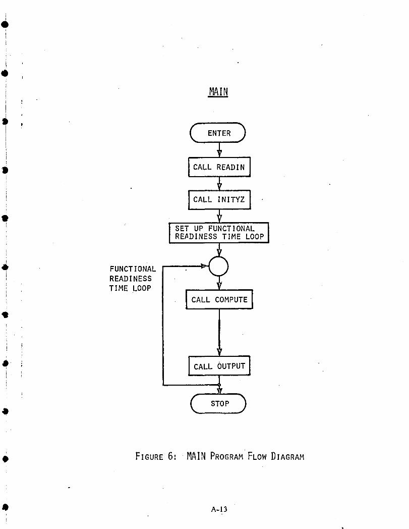
MAIN
l '
i CALL READINi
!; ! CALL INITYZ I
• .READINESS TIME LOOP
• FUNCTIONALREADINESSTIME LOOP
' 1 1i CALL COMPUTEE
i ,,
i
• STOP
• FIGURE6'•MAINPROGRAM FLOW DIAGRAM
Q A-13i

I•
•
•
•
II.Ii,
•
.-
I.i
I
I
I·I
II.IIII
C ENTER
tREAD NO OF DEPENDENCY STAGES NIS
S+NDS)READ NO OF NON-DEP. STAGES NDS
... I
r-+READ STAGE NO, MARKOV DIMENSIO~
NUMBER OF MODULES AND TRANSITIONRATES LMDA(I,J,K) FOR STAGE I
I
+READ FUNCTIONAL READINESSAND FAILURE PROBAB. TIMEENTRIES
tRY I READ NO. OF ENTRIES IN DEP. ARRAY, NARY I
,
~"
READ D~PENDENCY ~RRAYSN!ND(I AN~ NDEP I,J)J-1, ••• 1
~
~READ NO. ,OF FUNC. READ. CONF, NAV
V, t
R~tD2T~E FAILED MODULES, NA (I, K)K- , ,
'Ir
SCOF READ NO. OF SUCCESS CONF, NOSCOF,
, I/'
I READ SUCCESS CONF IC.O F( I ,.J) I,READ ACCURACY INDICATOR, NACCUR
.·EXIT
1=1, NA
1=1, NO
1=1, NA
FIGURE 7: READIN FLOW DIAGRAM •A-14
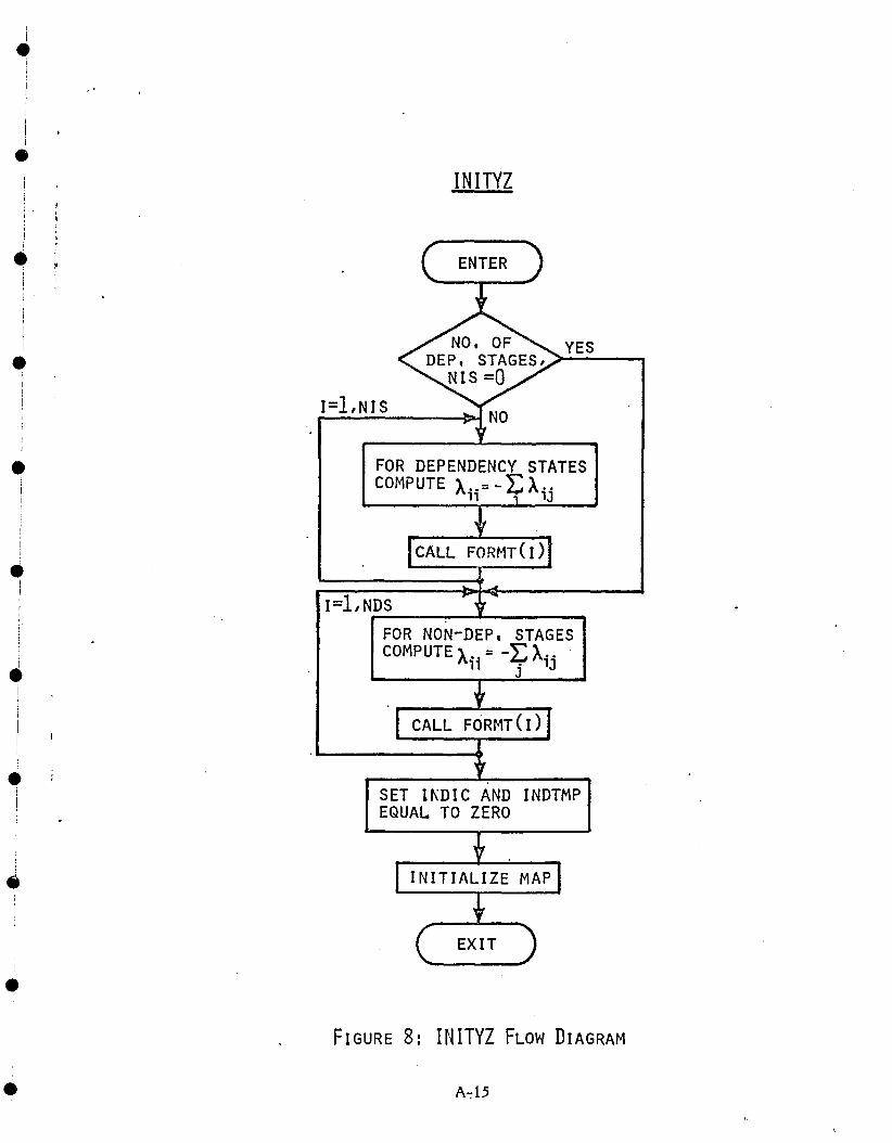
SET I~DIC AND INDTMPEQUAL TO ZERO
I
~
Ii•i
II•
•,
•
•Ii•I!
I•I
.!
•
•
INITYZ
YES
I=l,NIS
FOR DEPENDENCY STATESCOMPUTE X.. = -}; X·.
11 1J
I=l,NDS,..----------FOR NON-DEP. STAGESCOMPUTEX· = -}:X..
11 j 1J
FIGURE 8: INITYZ FLOW DIAGRAM
A-;15
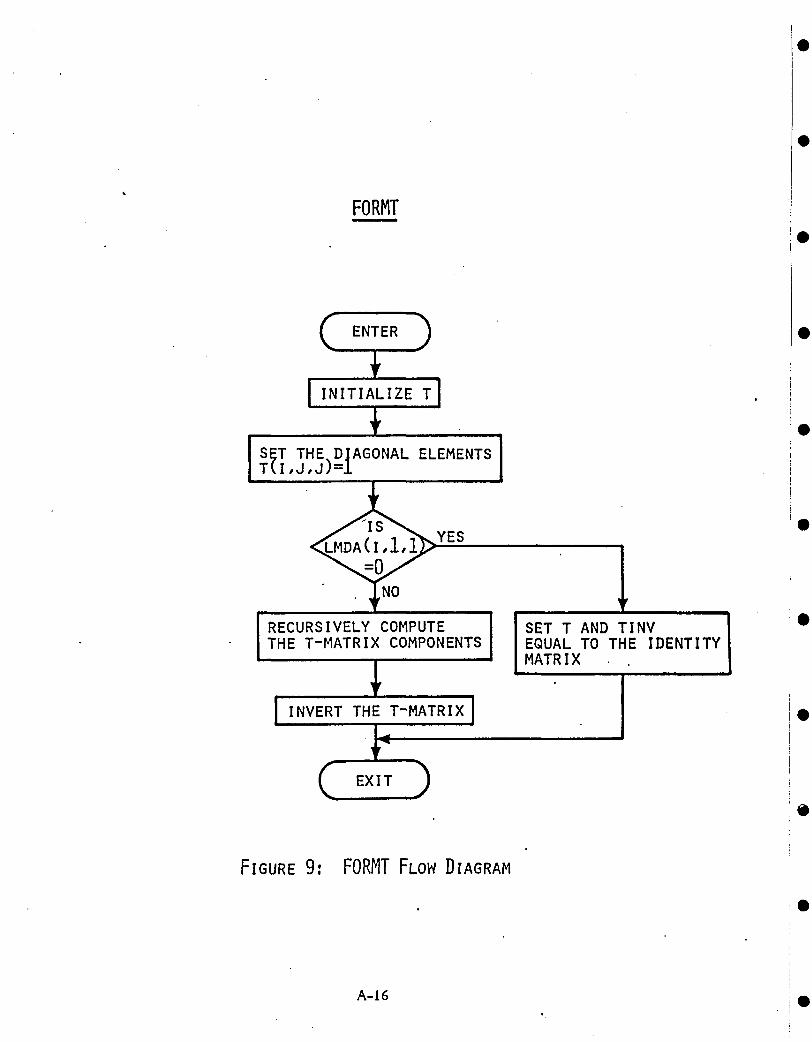
FORMT
S~T THE)DfAGONAL ELEMENTST{I,J,J =
YES
RECURSIVELY COMPUTETHE T-MATRIX COMPONENTS
INVERT THE T-MATRIX
FIGURE 9: FORMT FLOW DIAGRAM
A-16
SET T AND TINVEQUAL TO THE IDENTITYMATRIX
•
•
•
•
•
•
•
•
•
•
,•
•II
! :ii• J~:t
I
i•II
;•I
,
•
1.5.1 (cont'd)
probability of being in any of the t.wo last Markov states in any stage and FALUN is
the probability of being in t.he last Markov state in any stage. The array Spy which
contains the computational truncation error estimates is also computed. The range
of the above arrays are specified by the failure probability time range FPMT and
the increment FPDT read bYINITYZ, with the i element in each array correspond-.ing to a failure probability time T = i • FPDT. The Functional Readiness time is
transferred from MAIN to COMPUTE in the argument AVT. COMPUTE calls the
subroutine AVAIL to compute the Functional Readiness probability which is trans
ferred to MAIN in the argument ABVTY. The flow ~agram is shown in Figure 10.
OUTPUT" (Avr, AVBTY):
Outputs the arrays FAILP, FALUN and Spy together with the Functional Readiness.
(AVBr;ry) for a particular Functional Readiness time (AVT).
i•
•
•
'j
lI
"If
I'!
I
AVAIL (PRO, I, TIME):
Computes the Functional Readiness, PRO, at time TIME for the Functional Readiness
configuration specified by entry number I in the Functional Readiness table which is
read by READIN and stored in the common array NA (I, K). The AVAIL subroutine..also sets the indicator array INDIC corresponding to the Functional Readiness Con-
figuration and, in the case the Functional Readiness configuration specifies a dependency
module failure, rearranges the structure of the common arrays NIND and NDEP which
specifies module dependencies. The corresponding rearranged arrays are NTIND
and NTDEP.
The subroutine AVAIL uses the subroutine PROB to compute Functional Readiness and
SETETY to set the indicator array INDIC. The flow diagram is shown in Figure 11.
.. A-I7 .
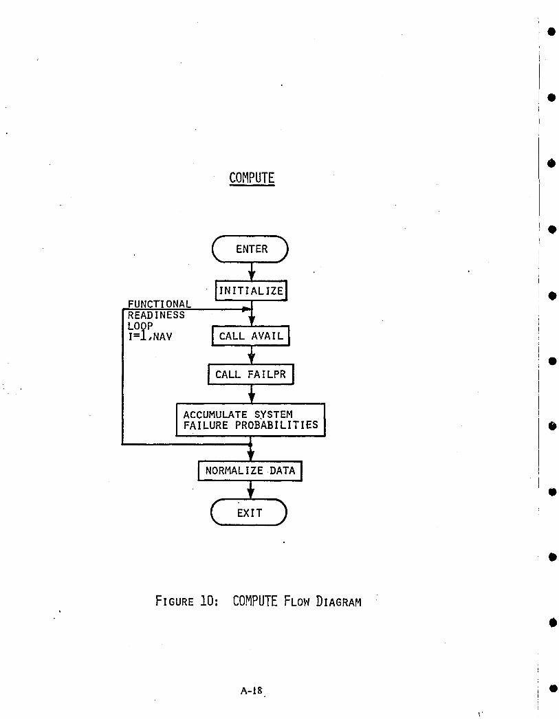
COMPUTE
FUNCTIONALREADINESSLOOPI=l,NAV
ACCUMULATE SYSTEMFAILURE PROBABILITIES
FIGURE 10: COMPUTE FLOW DIAGRAM
A-18
\'
•
•
•
•
•
•
•
•
•
•
•
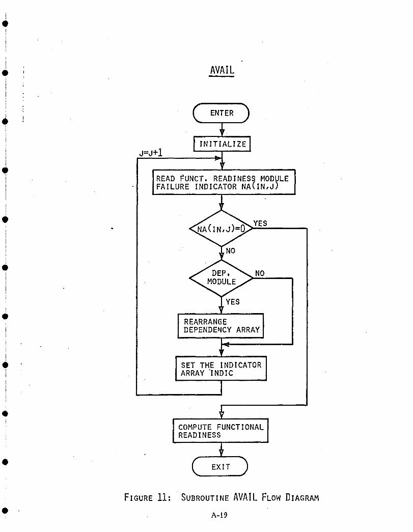
Q
i
• , AVAILI ii
' ( )' ' ENTER
!i J=J+l _._
IREAD_UNCT,READINESSMODULEIFAILURE INDICATOR NA(IN,J)
• l " _YESI
i - NO,
e NO
• I REARRANGE IDEPENDENCY ARRAY
• _ SET THE INDICATOR IARRAY INDICl
14
° _COMPUTE FUNCTIONALREADINESS
,._
• ( EXIT _
FIGURE11' SUBROUTINEAVAILFLOW DIAGRAM
• A-19

1. o.1 (cont'o}
PROB (ISTAGE, IENTRY, IEXIT, P, TIME):
This subroutine computes for stage ISTAGE, the probability P of being in Marker state
IEXIT at time TIME given state IENTRY at time zero. The subroutine uses the pre-
viously, in FORMT, calculated matrices T and TINV.
SETETY (J!_
The subroutine sets the failure condition array INDTI_IP according to the module failure
pattern specified by entry number J in the dependency table which specified the system
dependency structure. The flow diagram is shown in Figure 12. •
STRIP (INPUT, NSTGE, NSTATE):
Finds the stage number XX and state Y from a three digit number INPUT = XXY.
FAILPR (FALP, FALND, SPI:
This subroutine computes the failure probability arrays FAILP and FALUN for a certain
Functional Readiness configuration specified by the status of the array INDIC which
was set in AVAIL. It uses the (rearranged) dependency arrays NTIND (I) scanning •
through all entries I and failing combinations of dependency modules NTIND (I)
which in turn causes non-dependency modules NTDEP (I, J), J = 1, 2, ... to fail.
This is the actual implementation of the above described ,'exhaustive conditioning" a
approach. The probability of each combination of dependency module failure states is
computed by calling the subroutine INDFP, and the conditional probability of the non-
dependency modules failing, given the particular combination of dependency module
failures, is computed by calling DEPFP. The system failure probability is then •
computed by multiplying these two probabilities and summing over the different
dependency module failure combinations. To avoid calling the subroutine PROB
repeatedly all needed transition probabilities are computed initially by calling PRINTZ
which stores those probabilities in the array PROBAB which is common for INDFP •
and DEPFP.
Combinations of up to two different dependency mod_le failures are considered if
the accuracy indicator NACCUR entered by READIN is set to zero. With NACCUR = 1, •
combinations of up to three dependency module failures will be considered.
A-20 li
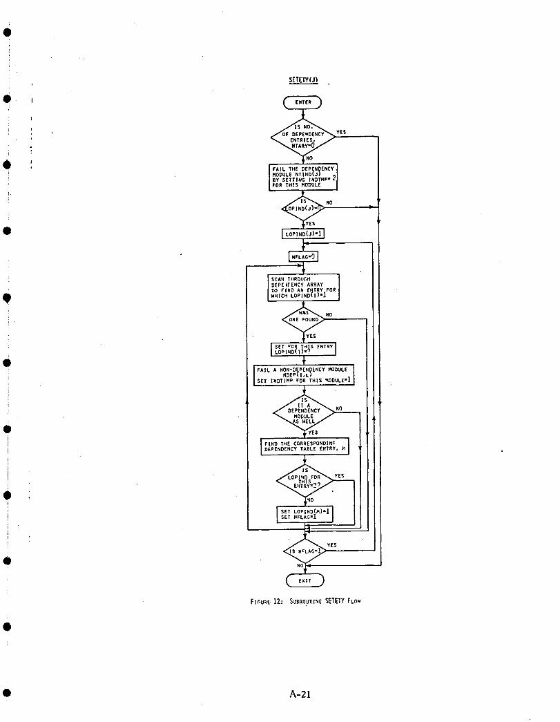
O
SETETY(J)
e ,
i YES
,ilk
W . I rAILTHEDEPeNdeNCYIi | MODULE NTIND_J/ _l
I BY SETTING INDTHP = Z|THIS MODULE I
i
0 I t°'lN°O)'lIL.
J SCAN 1 ItROUGHJ DEPE t[ ENCY ARRAYITOFXNOANENTRYFO_Iw.ic.LOPIND(I)'I
l SET €OQ IH_S ENTRYLOPIND/I) =f J
• . _! SET |NDTIHP FOR THIS '_IDULE =1
F NOi
e
i DEPENDENCY TAEL[ ENTRY,
_o
: ISET LOPIND(M)'IISET NFLAG=I
i YES
°Ft_URE.1Z: SUBROUTINES_ETYFLnW
• A-21

1.5. 1 (cont'd)
The truncation error, caused by not covering of possible combinations of dependency Qmodule failures, is the difference between unity and the sum of the probabilities of
all considered dependency module combinations. A flow diagram over the subroutine
FAILPR is outlined in Figure 13.
PRINTZ ITIME, NIS, NDS, DIM):
Computes Markov transition probabilities from state K to state J with J -_K for all
system stages and stores the result in the array PROBAB. •
EQUAL (A, B!:
Equalizes the two dimensional array A with the two dimensional array B.
INDFP (PR, FP, FPU, K):
Computes the probability PR of a certain dependency module failure pattern specified
by the state of the array INDTMP. The possibility that this specified combination
leads to system failure is also computed and the tw_ failure mode probabilities are •
stored in FP and FPU. The flow diagram is in Figure 14.
BINO(M,N, Ix'):
• Computes the binomial coefficient K = !I
DEPFP (PFAIL,PUNDET):
Computes theconditionalprobabilitiesoftwo systemfailuremodes givena particular
dependencymodulefailurestatewhichcausesfailureofnon-dependencymodulesas
specified by the status of the array INDTMP. It also scans through the stage success
table and accumulates success probabilities over all combinatious of non-dependency
stages equivalent to system success. The flow diagram may be found in Figure 15.
A-22 •
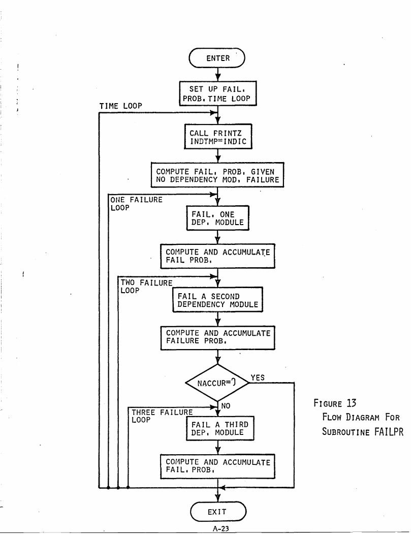
, ENTER, . I
' SET UP FAIL,
]PROB,TIME LOOP
IME LOOP _
INDTMP=INDIC
l
COMPUTEFAIL, PROB, GIVEN INO DEPENDENCY MOD, FAILUREI
ONE FAILURE _
LOOP I [
FAIL, ONEDEP, MODULE
.
TWOFAILURE
LOOP IFAIL A SECOND 1DEPENDENCY MODULE
ICOMPUTE AND ACCUMULATEIFAILURE PROB.
• YES
_!NO FIGURE 13THREEFAILURE
"¥_ l FLOW DIAGRAM FORLOOPFAIL A THIRD I
DEP, MODULE I SUBROUTINEFAILPR
I iCOMPUTE AND ACCUMULATEFAIL,PROB,
A-23
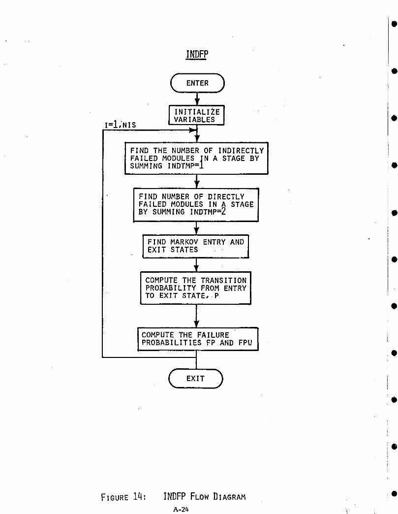
INDFP
0
I=I,.NI S VARIABLES •
FIND THE NUMBER OF INDIRECTLY
FAILED MODULES IN A STAGE BYSUMMING INDTMP=_ •
FIND NUMBER OF DIRECTLYFAILED MODULES IN _ STAGEBY SUMMING INDTMP=Z
.I IND MARKOV ENTRY AND]EXIT STATES •
COMPUTE THE TRANSITIONPROBABILITY FROM ENTRYTO EXIT STATE, P
"COMPUTE THE FAILURE !PROBABILITIES FP AND FPU
t "(_x_,)
FIGURE14, INDFPFLOW DIAGRAM •
A-24 _:.

DEPFP
( ENTERFIND THE NUMBER OF INDIRECTLYFAILED MODULES IN A STAGE BYSUMMING THE MODULES FOR WHICHINDTMP=I
!F,__ _A_OV_N__ ]
p
COMPUTE FAILURE PROBABILITIES lFP AND FPU
r
i
IACCUMULATE SURVIVAL IPROBABILITIES
i ii
1
SCAN THE SUCCESS CONFIGURATIONS TO IACCUMULATE SYSTEM SURVIVAL PROBABILITIES
, _ , i
EXIT _ FIGURE15: DEPFPFLOWDIAGRAM
A-25

2.0 CARSRA -- A USER'S GUIDE
2.1 General Q
The CARSRA program is coded in FORTRAN IV with approximately 700
FORTRAN statements. It requires 100,000 core locations to run, and
the execution time varies with the complexity of the system to be analyzed
and the selected program option, the typical execution time being in the
range of 1-30 seconds.
2.2 Input Description •All input data is on punched cards and must be input in a prescribed order.
The following comments are made in relation to Table 1 which specifies
required" input data, the corresponding variable names used by the program,
and the input format.
2.2.1 Dependency and Non-Dependency Stages
The system is partitioned into dependency and non-dependency stages with a
failure of a dependency stage module causing failure of a module in a dif- •
ferent stage. In cases where a stage both is a dependency and a non-
dependency stage, it will, in the program input, be identified as a depen-
dency stage.
Dependency stages are assigned numbers in the range 1-20 consecutively
starting by 1. If failure of a certain dependency stage module causes another
dependency stage module to fail, the former stage should be assigned a
lower stage number than the latter. Dependency stage numbers should be •
assigned in consecutive order without leaving a number unassigned inside
the array.
Non-dependency stages are assigned numbers in the range 21-50 consecu-
tively starting with 21.
2.2.2 Sta_e Dimension, Numbers of Modules and Transition Rates
The assigned stage number (NST), the dimension (NDIM) and the number of •
modules in the stage (MODN) information is entered on one card. The
dimension specifies the number of states in the Markov model for the stage
and is used to control the read in of the following (NDIM-1) cards which QA-26
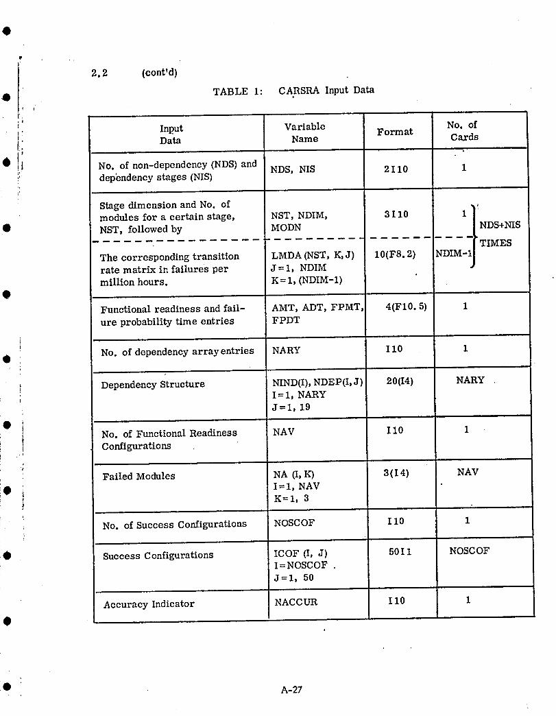
I 2.2 (cont'd)• TABLE 1: CARSRA Input Data
t
i:i
,,_ Input Variable Format No. of
i: Data Name Cards
!'• ! No. of non-dependency (NDS) and NDS, NIS 2110 1,_ dependency stages (NIS)
Stage dimension and No. of . ,modules for a certain stage, NST, NDIM, 3 1 i0 1
• NST, followed by MODN NDS+NISTIMES
The corresponding transition LMDA (b/ST, K, J) 10(F8.2) NDIM-1rate matrix in failures per J =1, NDIMmillion hours. K = 1, (NDIM-1)
9Functional readiness and fail- AMT, ADT, FPMT, 4(F10.5) 1
ure probability time entries FPDT
No. of dependency array entries NARY 110 1
I Dependency Structure NIND(I), NDEP(I, J) 20(I4) NARYI =1, NARYI
J=l, 19
• i No. of Functional Readiness NAV 110 1,iConfigurations
.t
• Failed Modules NA (I, K) 3 (I 4) NAVI--1, NAV
:_ K= i, 33
: NO. of Success Configurations NOSCOF 110 1{
• Success Configurations ICOF (I, J) 50I 1 NOSCOF! I =NOSCOF
J=l, 50
Accuracy Indicator NACCUR 110 1
I
@ : A-27
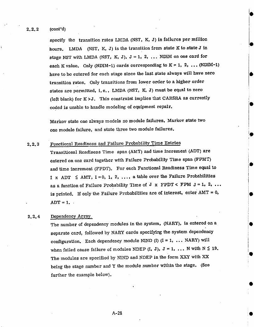
\
2.2.2 (cont'd)
specify the transition rates LMDA (NST, K, J) in failures per million
hours. LMDA (NST, K, J) is the transition from state K to state J in
stage NST with LMDA (NST, K, J), J = 1, 2, . .. NDIM on one card for
each K value. Only (NDIM-1) cards corresponding to K = 1, 2, ... (NDIM-1)
have to be entered for each stage since the last state always will have zero
transition rates. Only transitions from lower order to a higher order
states are permitted, i.e., LMDA (NST, K, J) must be equal to zero
(left blank) for K >J. This constraint implies that CARSRA as currently
coded is unable to handle modeling of equipment repair.
Markov state one always models no module failures, Markov state two
one module failure, and state three two module failures.
2.2.3 Functional Readiness and Failure Probability Time Entries !
Transitional Readiness Time span (AMT) and time increment (ADT) are iF
entered on one card together with Failure Probability Time span (FPMT) iI
and time increment (FPDT). For each Functional Readiness Time equal to i•!
I x ADT < AMT, I = 0, 1, 2, . .., a table over the Failure Probabilities ;i
as a function of Failure Probability Time of J x FPDT < FPM J = 1, 2, ... l
is printed. If only the Failure Probabilities are of interest, enter AMT = 0, •
ADT = 1..
2.2.4 Dependency Array
The number of dependency modules in the system, (NARY), is entered on a •
separate card, followed by NARY cards specifying the system dependency
configuration. Each dependency module NIND (I) (I = 1, ... NARY) will
when failed cause failure of modules NDEP (I, J), J = 1, ... N with N <_.19.
The modules are specified by NIND and NDEP in the form XXY with XX
being the stage number and Y the module number within the stage. (See
further the example below).
I

2.2.5 Functional Readiness Table ,D The number of Functional Readiness configuration entries NAV is specified
on a separate card followed by NAV cards, one for each configuration.
i Each configuration is characterized by up to 3 failed NA (I, K)modules
K = 1, 2, 3 where the module is indicated by XXY as before (2.2.4). TheFunctional Readiness probability computed by the program is the probability
• 2.2.6 Sta_e°fhavingsuccessanyoneTableOfthe specified system failure patterns at a given time.NOSCOF, entered or. a separate card, specifies the number of stage failure
patterns equivalent to system success. One card is thereafter entered
for each pattern which is specified by a 1 (one) in a column corresponding to
• a failed stage• If all stages are essential for system success, NOSCOF is
equal to one followed by a blank card. If two stages, for example the non-
dependency stages 21 and 22, are redundant three cards are required:
O 1) Col 21=0Co122=0; 2) Col 21=1Co122=0; 3) Col 21=0Co122=1.
2.2.7 Accuracy Indicator
_, The accuracy indicator, NACCUR, specifies the level to which conditioning!e
i upon the combinations of dependency module failure is performed. If NACCUR = 0i (lower accuracy setting) all combinations of zero, one and two dependency
I module failures will be considered plus failure combinations equivalent to
i system failure. If NACCUR = 1, up to three dependency module failureswill be considered plus failure combinations equivalent to system failure.ti The higher accuracy could be required when treating a system with high
module redundancy (for example a quad system) or when the mission time is
_• long. However, the program run time could be in the order of ten times
longer for the higher accuracy setting.
The truncation error is indicated by an accuracy number. The correct failure$
probability value will lie in the range.
printed output value, printed output value + accuracy]
• A-29
2.3 Output Description
A tableover system failureprobabilitiesare printedfor each Functional
Readiness Time I x ADT = AMT. The tableentriesare Failure Prob-
abilitytimes J x FPDT < FPMT. the probabilitiesof a detectedand an
undetectedsystem failure(orany othertwo failuremodes), and the trun-
cationerror band, •
A__O •
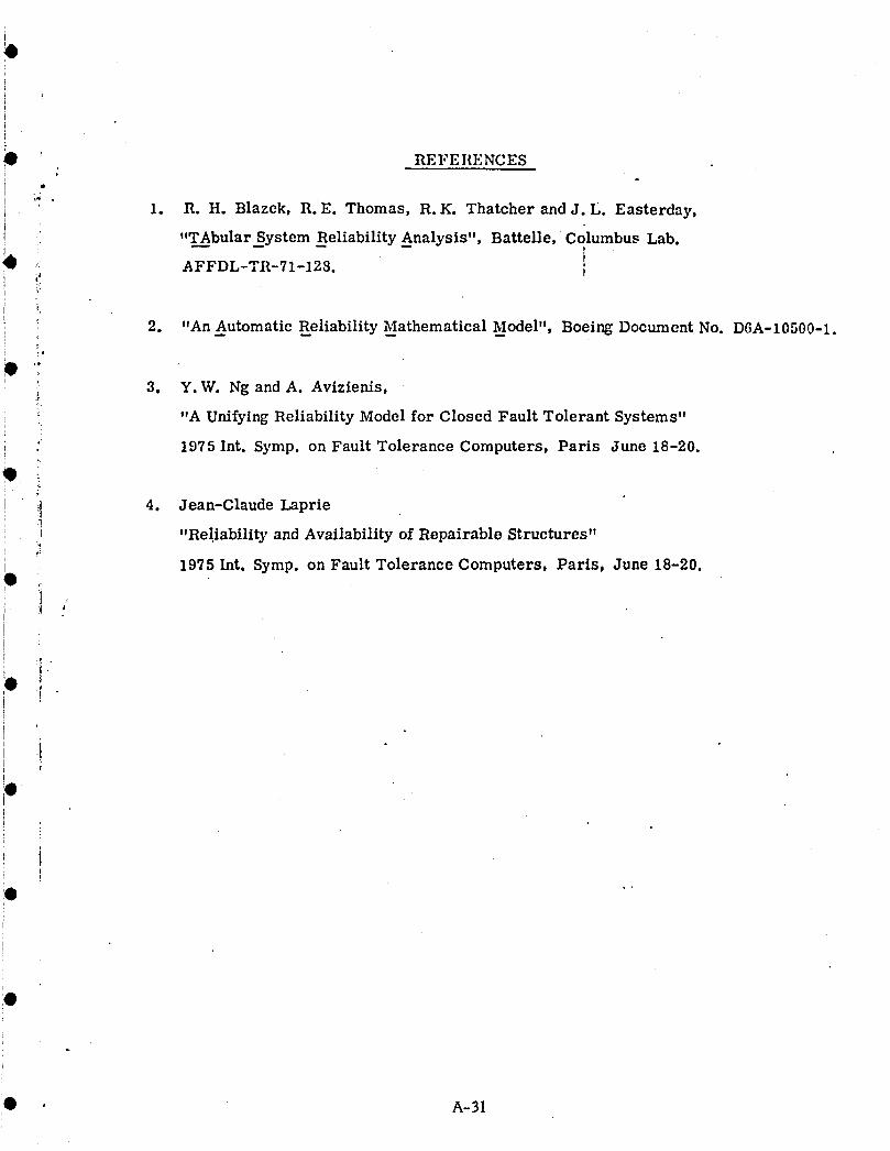
! REFERENCES
r
I *" " 1. R.H. Blazek, R.E. Thomas, R.K. Thatcher and J.L. Easterday,I
! ,,TAbular_System Reliability Analysis", Battelle, Columbus Lab.
:: AFFDL-TR-71-128. I
i 2. "An Automatic Reliability Mathematical Model", Boeing Document No. D6A-10500-1.
_ 3. Y.W. Ng and A. Avizienis,
"A Unifying Reliability Model for Closed Fault Tolerant Systems"
' 1975 Int. Symp. on Fault Tolerance Computers, Paris June 18-20.
4. Jean-Claude Laprie
"Reliability and AvailabilityofRepairable Structures"
1975 Int.Symp. on FaultTolerance Computers, Paris, June 18-20.
j'
I!
l
i
i
I A-31

APPENDIX B
AIRLINE COMPONENT REMOVAL DETAILS
Failure rates for each of the flight control modules are required for the reliability
analysis. To derive these rates_ airline component removal histories are used. This
appendix is a collection of several 747 operators reports giving details of unscheduled
• component removals on a yearly basis. The reports cover the years 1970through 1976.
• 8-Ii
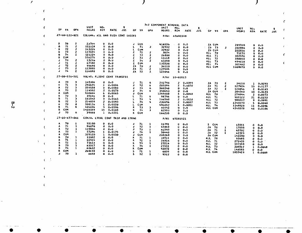
, ) )(
I
( (747 COMPONENT REMOVAL DATA
UNIT NO. _ UNIT NO. Z . UNIT NO. _ 1.( OP Yk QPA HOURS REH RATE JU$ OP YR QPA t'I_URS REM RATE JUS OP YR QPA HOURS REN RATE JUS
( 27-u0-122-021 COLUMN. A|L kNO ELEV CONT tASSY| PIN: 65U80308(
5 70 2 2_764 0 0.0 J _UH 616536 0 0.0 ZA CO½ 2845bD 0 0.08 71 2 121028 0 0.0 L 71 2 32932 0 0.0 ZB 73 2 202836 0 0.0B 72 2 143226 0 0.0 L CUH 32932 0 0.0 Z5 CUM 202836 0 0.0
b 73 2 127034 0 U.O Z Tl 2 3626 U 0.0 ALL 70 71170 O 0.0 C8 74 2 121224 0 O.O Z 72 2 26888 0 0.0 ALL 71 352570 0 0.08 CUH 536276 0 0.0 Z 73 2 41668 0 0.0 ALL 72 388858 0 0.0
, J 70 2 13296 0 0.0 Z 74 2 63358 0 0.0 ALL 73 494618 0 0.0 (J 71 2 67582 0 0°0 Z £UN 135538 0 0.0 ALL 76 301462 0 0.0J 72 2 95698 0 0.0 ZA 70 2 3611O 0 0.0 ALL CUM L608678 0 0.0
( J 73 2 123O80 0 0.0 ZA 71 2 127606 0 0.0J 74 2 116880 0 0.0 ZA 72 2 123066 0 0.0
( 27-00-576-581 VALVEt FLIGHT CONT TRANSFER PIN: 10-60813
A 70 3 165300 0 0.0 J 71 6 202766 2 0.0099 ZA 70 2 36110 1 0.0293( A 71 3 290636 1 0.0034 J 72 6 287094 2 O.UOTO ZA 71 2 127404 15 0.1177
A 72 3 359538 3 0.0083 J 73 6 369260 O 0.0 ZA 72 2 123046 2 0.0163A 73 2 114592 .2 0.0175 J 74 6 350640 0 0.0 ZA CUM 284560 18 0.0633
( A CUH 930064 6 0.0065 J CUN 1249608 5 0.00_0 ALL 70 276944 2 0.00738 70 3 35646 0 0.0 L 71 6 98796 0 0.0 ALL 71 901122 21 0.0233B 71 3 181542 3 0.0165 L 73 4 166560 2 0.0120 ALL 72 986517 9 0.0091
_:; ( B 72 3 216839 2 0.0093 L 74 6 230696 2 0.0087 ALL 73 1240170 5 0.0060! _ 73 8 508136 1 0.0020 L CUH 496052 6 0.0081 ALL 76 1168825 11 0.0096
B 74 B 484896 _ 0.0186 R T3 3 81642 0 0.0 ALL CUM 4549578 48 0.0106( 8 CUN 1425059 15 0.0105 R 74 3 82593 0 0.0
J 70 6 "39888 1 0.0251 k CON 164235 0 0.0
( 27-00-677-061 CON/At LTRAL CONT TRIH AND CTRNG P/NI 65880521
A TO 1 55100 0 0.0 J 71 1 33791 0 0o0 $ CUH L5551 0 0.0( A 71 1 96878 0 0.0 J 72 1 47869 O 0.0 ZA 70 1 17055 O 0.0
A 72 1 119846 O 0.0 . J 73 1 61560 0 0.0 ZA 71 1 63702 O 0.0A 73 1 57296 1 0.0175 J 74 1 58460 0 O.O ZA 72 1 61523 0 0.0
( A CUH 32_120 1 0.003D J CUM 208268 0 0.0 ZA CUH 142280 O 0.0B 70 1 11882 0 0.0 R 71 1 10511 0 0.0 ALL 70 90685 0 0.0
\ 8 71 " 1 60516 0 0.0 R 72 1 26816 0 0.0 ALL 71 271435 0 0.0 "t b 72 1 71613 0 0.0 R 73 1 27216 0 0.0 ALL 72 337159 0 0.0
B 73 1 63517 0 0.0 R 76 1 27531 0 0.0 ALL 73 209567 1 0.0048B 74 1 60612 0 0.0 R CUH 92072 0 0.0 ALL 74 146583 0 0.0B CUN 268138 0 G.O 5 71 1 6039 0 0.0 ALL CUH 1055429 1 0.0009J 70 1 6668 0 0.0 $ 72 1 9512 0 0.0
(
• 9 • • • • Q • €) • •
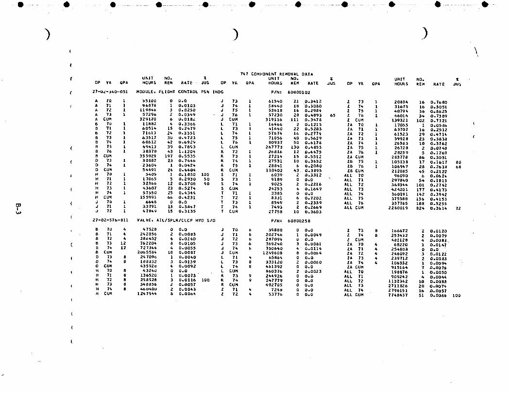
• O ........... e ....... O ................• ........................• .....................e ........... 4 ............ O ................. ...................e ...................• .....
) )( \
(
747 COMPONENT REMOVAL DATAr UhIT NO. X UNIT NUo Z UNIT NO. X
OP VR GPA HOURS REM RATE • JUS OP YR OPA HOURS REN RATE JUS OP YR OPA HOURS REM RATE JU$
( 27-U_-J60-O51 HODULE, FLIGHT CONTROL PSN |NOG P/N: 60800102
A 70 1 _5100 0 0,0 J 73 1 61560 21 0,3612 Z 73 1 20836 16 0,7680{ A 71 1 96878 1 0,0103 J 76 L 58660 18 0,3080 Z 76 1 31679 16 O,5051
A 72 1 119866 3 0,0250 J 75 1 53618 16 0,2984 Z 75 1 60794 36 O,8825A 73 1 57296 2 O,0369 J 76 1 5T230 28 0,4893 65 Z 76 1 66016 36 0,7389A CUH 329120 6 0,018_ J _UH 319116 111 0,3678 Z CUM 139321 102 O,7321B 70 1 11882 6 0,3366 L 71 1 16466 2 0,1215 ZA 70 1 17055 1 O,0586 (B 71 1 60516 15 0,2679 L 73 1 61660 22 0,5283 ZA 71 1 63702 16 0,2512
B 72 1 71613 24 0.3351 L 76 1 57676 16 0.2774 ZA 72 1 61523 29 0.6714 (B 73 1 63517 3U 0,6723 L 75 1 71056 60 0,5629 ZA 73 1 59928 23 0,3838B 74 1 60612 62 0,6929 L 76 1 80937 50 0,6178 ZA 74 1 26583 10 0,3762
( B 75 1 49413 39 0,7893 L CUM 267773 130 0,6855 ZA 75 1 2672B 2 D,0748B 76 1 38378 63 1,1206 R 72 1 26816 12 0,4475 ZA 76 1 28259 5 O,1769B CUH 355929 197 0,5535 R 73 1 27214 15 0,5512 ZA CUN 283778 86 0o3031
( 0 73 1 30887 23 0,7666 R 76 1 27531 10 0,3632 ZB 75 1 105138 17 Oo1617 80D 76 1 23604 1 0,0426 R 75 1 288_1 6 0,2080 Z8 76 1 106967 28 0,2618 68D CU_ 56491 24 0,4406 R CUM 110602 63. 0,3895 28 CUN 212085 45 O,2122
f H 70 ! 5605 1 0,1850 100 S 71 1 6039 2 O,3312 ALL 70 96090 6 0,062_H 71 1 17065 5 0,2930 50 5 73 1 9189 0 O,O _ ALL 71 297860 54 Oo1813H 72 1 32366 12 0,3708 90 5 76 1 9025 2 O,2216 ALL 72 368344 IO1 0°2742
( H 73 1 63607 23 0,5276 $ CUM 24253 4 0,1649 ALL 73 424201 177 O,4173H 74 1 57550 25 0.6344 T 71 1 3385 0 0.0 ALL 76 360191 142 0.3962H CUM 15599_ 66 0,4231 T 72 1 8331 6 0,7202 ALL 75 375588 156 O,4153
( J 70 1 6648 0 0,0 T 73 1 8549 2 0,2339 ALL 76 357765 188 0,5255i1_ J 7L 1 33791 13 0,38_1 T 74 1 7493 2 0,2669 ALL CUM 2280019 826 0,3614 72
J 72 1 47849 15 0,3135 T CUM 27758 10 0,3603(
27-02-576-811 VALVE, AIL/SPLR/CLCP HYO S/O P/N= 60800258
B 7d 4 47528 0 0,O J 70 6 39888 0 O,0 Z 73 8 166672 2 0,01208 71 6 262056 2 0.0083 J 71 6 202746 1 0.0049 Z 76 8 253432 2 0.0079B 72 4 28_652 6 0,0140 J 72 6 287094 0 0,O Z CUM 481128 4 0,0083
( 8 73 12 7&2204 8 0.0105 J 73 6 369260 3 0.0081 ZA TO 4 68220 1 0.01478 7_ 12 727364 4 0.0055 J 76 b 350660 4 0.0114 ZA 71 4 254808 0 0°0.8 CU_ 2065584 18 0,0087 J CUM 1249608 8 0,0064 ZA 72 _ 246092 3 0,0122D 73 8 247096 1 0,0060 L 71 6 65866 0 0,0 ZA 73 4 239712 2 0,0083
( D 7_ 8 188832 3 0,O159 L 73 8 333120 2 0,0060 ZA 74 4 106332 1 0,0096O CUH 43592u 4 0,0092 L T6 8 461392 0 0,0 ZA CUM 915164 7 0,0076
t H 70 8 43240 0 0,O L CUH 860376 2 0,0023 ALL 70 198876 1 0,0050H 71 8 136520 1 0,0073" R T3 9 264926 0 0,O ALL 71 909242 4 O,006_H 72 8 258928 3 O,0116 100 R 74 9 247779 0 O,O ALL 72 1132342 10 O,0088
( H 73 8 348656 2 0,0057 R CUH 692705 0 0,0 ALL 73 2711826 20 0,0074H 74 8 660_0U 2 0,0043 Z 71 6 724u 0 0,O ALL 74 2796151 16 O,0057H CUH 1247944 8 0,0064 Z 72 4 53776 0 0,0 ALL CUM 7768637 51 O,OO6& 100
(
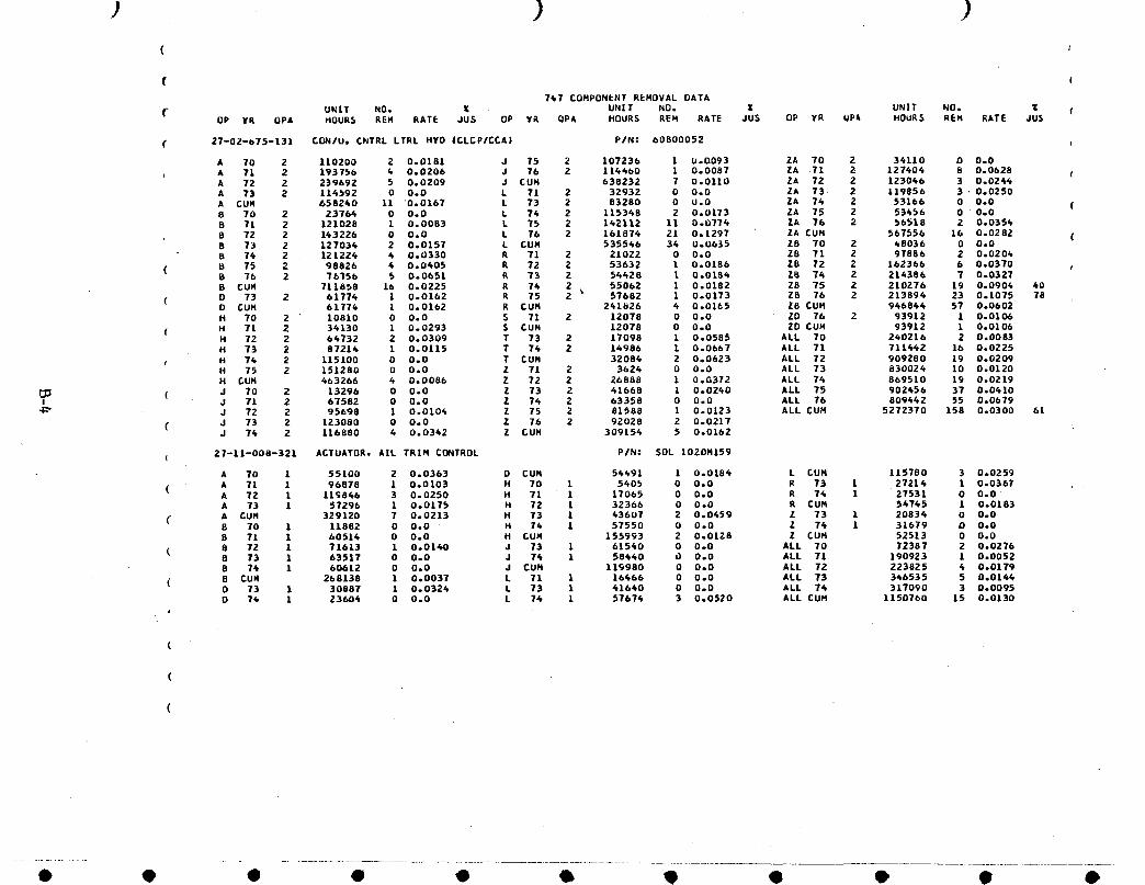
( I
747 COMPONENT REMOVAL DATA
UNIT NO. _ UNIT NO. Z UNIT NO. _ fOP VR OPA HOURS REM RATE JUS OP YR OPA HOURS REM RATE JUS OP YR QP& HOURS REM RATE JUS
( 27-02-675-131 CON/Uo CNTRL LTRL HYO |CLCP/CCA) P/N: 60800052
A 70 2 110200 2 0.0181 J 75 2 10723& 1 0.0093 ZA 70 2 34110 0 0o0A 71 2 19375b _ 0.0206 J Tb 2 114400 1 0.0087 ZA .71 2 127404 8 0.0628A 72 2 239692 5 0.0209 J CUM 638232 7 0.0110 ZA 72 2 123046 3 0.0264A 73 2 116692 0 0.0 L 71 2 32932 0 0.0 ZA 73 2 119856 3" 0.0250
A CUM 658240 11 "0.0167 L 73 2 83280 0 U.O ZA 74 2 53166 0 0.0 (8 70 2 23764 0 0.0 L 7_ 2 115348 2 0.0173 ZA 75 2 53656 0 0.08 71 2 121020 1 0.0083 L 75 2 142112 11 0.0774 ZA 76 2 56518 2 0.0354
8 72 2 143226 0 0.0 L 76 2 161874 21 0.1297 ZA CUM 567556 16 0.0282 (B 73 2 127034 2 0,0157 L CUM 535546 36 0.0635 28 70 2 48036 0 0.0B 74 2 121224 6 0.0330 R 71 2 21022 0 0.0 28 71 2 97886 2 0.0206
( B 75 2 98826 4 0.0405 R 72 2 53632 1 0.0186 Z8 72 2 162366 6 0.03705 Tb 2 76356 5 0.0651 k 73 2 54628 l 0.0184 ZB 74 2 214386 T 0°0327B CUH 711858 16 0.0225 R 74 2 _5062 1 0.0182 Z8 75 2 210276 19 0.0906 40
( 0 73 2 61774 1 0.0162 R 75 2 _ 57682 1 0.0173 Z8 76 2 213894 23 0.1075 7aD CUM 61776 1 0.0162 R CUH 261826 6 0.0165 ZB CUM 946844 57 0.0602H TO 2 " 10810 0 0.0 S 71 2 12078 0 0.0 ZD 7& 2 93912 1 0.0106
( H 71 2 34130 1 0.0293 S CUM 12078 0 0.0 ZD CUH 93912 1 0.0106H 72 2 66732 2 0.0309 T 73 2 17098 1 0.0585 ALL TO 240216 2 0,0083H 73 2 87214 1 0.0115 T 74 2 14986 1 0.0667 ALL 71 711442 16 0.0225
t H 74 2 115100 0 0.0 T CUN 32084 2 0.0623 ALL 72 909280 19 0.020gH 75 2 151280 0 0,0 Z 71 2 3626 0 0.0 ALL 73 830024 10 0.0120H CUH 463266 4 0.0086 Z 72 2 26888 1 0.0372 ALL 76 869510 19 0.0219
(_ ( J 70 2 13296 0 0.0 Z 73 2 41668 1 0.0260 ALL 75 902456 37 0.0410I J 71 2 67582 0 0o0 Z 76 Z 63358 0 0.0 ALL 76 809662 55 0.0b79
J 72 2 95698 1 0.0104 Z 75 2 81588 1 0.0123 ALL CUM 5272370 158 0.0300 61
( J 73 2 123080 0 0.0 Z 76 2 92028 2 0.0217J 74 2 116880 6 0.0342 Z CUM 309154 5 0.0162
( 27-11-008-321 ACTUATOR, AEL TR1M CONTROL P/N= SDL 1020H159
A TO 1 55100 2 0.0363 D CUM 54491 1 0.0186 L CUH 115780 3 0.0259
( A 71 1 96878 1 0.0103 H 70 1 5405 0 0.0 R 73 1 27214 1 0.0367A 72 l 11_846 3 0.0250 H 71 1 17065 0 0.0 R 74 1 27531 0 0.0A 73 1 57296 1 0.0175 H 72 1 32366 0 0.0 R CUM 56745 1 0.0183
( A CUH 329120 7 0.0213 H 73 1 63607 2 0.0459 Z 73 1 20834 0 0.0B 70 1 11882 0 0.0 H 74 1 57550 0 0.0 Z 74 1 31679 0 0.0B 71 1 60514 0 0.0 H CUM 155993 2 0.0128 Z CUM 52513 0 0,0
( 8 72 1 71613 1 0.01_0 J 73 1 61540 0 0.0 ALL 70 72387 2 0.02768 73 1 63517 0 0.0 J 74 1 58440 0 0.0 ALL 71 190923 1 0.00528 74 1 60612 0 0.0 J CUM 119980 0 0.0 ALL 72 223825 6 0.0179
( 8 CUH 268138 1 0.0037 L 71 1 16466 0 0.0 ALL 73 346535 5 0.0146D 73 1 30887 1 0.0324 L 73 1 41640 0 0.0 ALL 74 317090 3 0.00950 74 1 23606 0 0.0 L 74 1 57674 3 0.0520 ALL CUM 1150760 15 0.0130
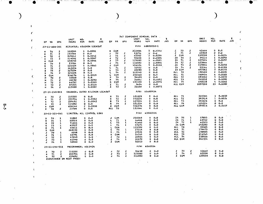
) ) )!
fT&7 COMPONENT REMOVAL OATA
UNIT NO. Z UNIT I_U. I UNIT NO. Z I( UP YR OPA HOURS REN RATE J_S UP YR OPA HUURS KEN PATE JUS UP YR QPA HOURS REM RATE JUS
( 21-|1-008-361 ACTUATbRt AILERON LOCKOUT PiN: 60880050-1
A To 2 110200 I 0.0091 H CUM 311986 5 0.0160 Z 73 2 41668 0 O.OA 71 2 1937_b G 0.0 J 70 2 1329o u O.U Z 74 2 63358 0 O.UA 72 2 2_96_Z 1 0.0062 J 71 2 67582 2 0.0296 Z CUN 135538 1 0.00T4A 73 2 114592 1 0.0087 J 72 2 956_8 1 0.0104 ZA TO 2 34110 1 0.0293A CUN 658260 3 0.0046 J 73 2 123080 1 U.0081 ZA 71 2 127406 2 0.0157 (B TO 2 2376_ 0 0.0 J 74 2 116880 1 0.0086 ZA T2 2 123046 0 0.08 71 2 121028 1 0,0003 J CUM 416536 5 0.0120 ZA 73 2 119856 3 0.0250B 72 2 143226 0 0.0 L 71 2 32932 0 0.0 ZA 7_ 2 53166 1 0,018a (8 73 2 127034 O 0.0 L 73 2 d3280 0 0.0 ZA CUH _57582 7 0.0153U 74 2 12122& 0 0.0 L 74 2 115348 0 0.0 ALL 70 192180 2 0,010€
( B CUH 536276 1 0.0019 L CUH 231560 0 0.0 ALL 71 500_56 6 0.0103H 70 2 10810 0 0.0 R 73 2 54428 0 0.0 ALL 72 693282 5 0.0072H 71 2 34130 1 0.0293 R 74 2 5_062 l 0.0182 ALL 73 751152 6 0.0080
( H 72 2 64732 2 0.0309 R CUM 10_90 1 0.0091 ALL 7_ 660138 _ 0.0062H 73 2 87214 1 0.0115 Z 71 2 3626 0 0.0 ALL CUH 2857208 23 0.0080H 74 2 115100 1 0.0087 Z 72 2 26_88 1 0.0372
(27-11-248-011 GEARBOX, OUTBD AILERON LOCK_JT P/N: &5680934
k 70 2 110200 0 0.0 B 71 2 121028 0 0.0 ALL 71 314784 1 0.0032A 71 2 193756 1 0.0052 B 72 Z 143226 0 0.0 ALL 72 382918 1 0,0026A 72 2 239_92 1 0.0062 B 73 2 12703_ 0 0,0 ALL 73 2_162& 0 0.0
A 73 2 116592 0 0.0 8 74 2 12122_ 0 0.0 ALL 74 121224 0 0.0(
A CUM 658240 2 0.0030 8 _UH 53b276 0 0.0 ALL CUM 1194516 2 0,0017_Jt 8 70 2 23764 0 0.0 ALL 70 1339&_ 0 0.0
(27-11-325-061 LIMITER, AIL CONTROL LOAO P/I_: 65880314
B 70 1 11882 0 0.0 J CUM 208268 0 0.0 ZA 70 1 1T055 0 0.08 71 1 60514 0 0.0 L 71 1 16466 0 0.0 ZA 71 1 63702 U 0.08 72 1 71613 0 0.0 L 73 1 416_0 0 0.0 ZA 72 1 61523 0 0.0
C 8 73 1 63517 0 0.0 L 74 1 57674 0 0.0 ZA CUN 142280 0 0.0B 74 1 60612 0 0.0 L CUH 115780 0 0.0 ALL TO 35585 0 0.0B CUH 268138 0 0.0 R 73 1 27216 0 0.0 ALL 71 174473 0 0.0
( J 70 1 6648 0 0.0 R 74 1 27531 0 0.0 ALL 72 180985 0 0.0J 7L 1 337gl 0 0.0 R CUH 5_745 0 0.0 ALL 73 21_745 0 0.0J 72 1 47849 0 0.0 Z 73 1 20836 0 0.0 ALL 74 235936 0 0.0J 73 1 61540 0 0.0 Z 74 1 31679 0 0.0 ALL CUH 8_1724 0 0.0J 76 1 58640 0 0.0 Z _UN 52513 0 0.0
27-11-396-011 PROGRAMMER, AILERON PIN: &500556
A TO 2 110200 b 0.0 J 72 2 9_698 0 0.0 Z 73 Z 41668 0 0.0A 71 2 193756 0 0.0 J 73 2 123080 0 0.0 Z 76 2 63358 0 0.0A 72 2 239692 0 0.0 J 74 2 11_880 0 O.U Z CUN 135538 0 0.0I£ONTINUED ON NEXT PAGEI
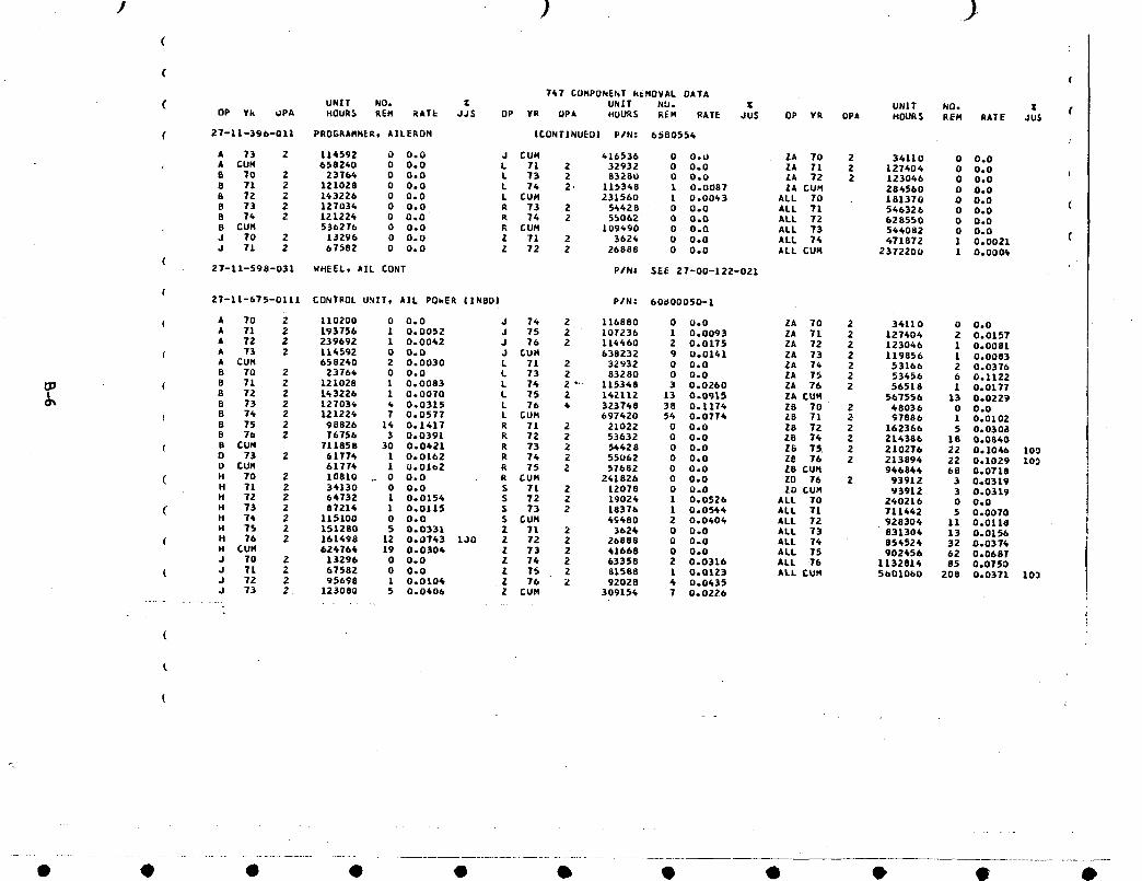
s ) .)(
( €741 £UMPONENT k_HOVAL DATA
UNIT NO. Z UNIT NU. Z UNIT NQ. Z (( OP Yk UPA HOURS REH KAT_ JJS UP ¥R UPA HOURS REH RATE JUS UP YR QPA HOURS REN RATE JU$
( 27-11-396-011 PROGRAHHEA, AILERON ICUNTINUEUI P/N: 6500554
A 73 2 116_92 0 0o0 J CUH 616536 0 O.U ZA 70 2 34110 0 0.0
A £UN 6582k0 0 0o0 L 71 2 32932 0 0.0 ZA 11 2 127404 0 0.0 (B TO 2 23T64 0 0.0 L 73 2 83280 0 O.U ZA 72 2 123066 0 0.0B 71 2 121028 0 0.0 L 74 2. 115348 1 0.0087 ZA CUH 284560 0 0.0
8 72 2 143226 0 0.0 L CUH 231560 1 0.00_3 ALL 70 181370 0 0.0 (B 73 2 127034 0 0.0 R 73 2 54428 0 0.0 ALL 71 546326 0 0.0B 7_ 2 121224 0 0o0' R 74 Z §5062 0 0.0 ALL 72 628550 0 0.0B CUH 536276 0 0.0 R CUM 109490 0 0.0 ALL 73 546082 0 0.0J TO 2 13296 0 0.0 Z 71 2 3624 0 0.0 ALL 74 671872 1 0.0021 (J 71 2 67582 0 0.0 Z 72 2 26888 0 0.0 ALL CUH 2372200 1 0,000_
(27-11-598-031 WHEEL, AIL CONT P/N: SEE 27-00-122-021
27-11-675-0111 CONTROL UNIT, AlL POKER (IN80| P/N: 60600050.-1
A 70 2 110200 0 0.0 J 74 2 116880 0 U.O ZA 70 2 36110 0 0.0A 71 2 193756 1 0.0052 J 75 2 107236 1 0.0093 ZA 71 2 127606 2 0.0157A 72 2 239692 1 0.0062 J 76 2 114660 2 0.0175 ZA 72 2 123046 1 0.0081A 73 2 114592 0 0.0 J CU_ 638232 9 0.0141 ZA 73 2 119856 1 0.0083A CUH 658260 2 0.0030 L 71 2 32932 0 0.0 ZA 74 2 53166 2 0.0376B 70 2 23764 0 0.0 L 73 2 83280 0 0.0 ZA 75 2 53456 6 0.1122
1_3 B 71 2 121028 1 0.0083 L 74 2 "" 115368 3 0.0260 ZA 76 2 56518 1 0.0177! B 72 2 143226 1 O.OOTO L T5 2 162112 13 0.0915 ZA ¢UH 56?556 13 0.0229
O_ B 73 2 127034 _ 0.0315 L 76 4 323748 38 0.1174 ZB 70 2 68036 0 0.08 74 2 12122_ 7 0.0577 L CUM 697420 56 0.0776 28 71 2 87886 1 0.0102B 75 2 98826 14 0.1417 R 71 2 21022 0 0.0 Z8 72 2 162366 5 0.03088 76 2 76756 3 0.0391 K 72 2 53632 0 0.0 ZB 74 2 214386 18 0.0840B CUM 711858 30 0.0421 R 73 2 54628 0 0.0 Z6 ?5_ 2 210276 22 0.1046 109O 73 2 61774 1 0.0162 R 74 2 55062 0 0.0 Z8 76 2 213896 22 0.1029 1000 £UH 61774 1 0.01o2 R 75 2 57682 0 0.0 28 CUH 966864 68 0.0718
( H 70 2 10810 .. 0 0.0 R CUH 241826 0 0.0 ZD 76 2 93912 3 0,0319H 71 2 34130 0 0.0 S 71 2 12078 0 0.0 ZD CUM 93912 3 0.0319H 72 2 66732 1 0.0154 S 72 2 19024 1 0.0526 ALL 70 240216 0 0.0
( H 73 2 87214 1 0.0115 S 73 2 18376 1 0.0546 ALL 71 711642 5 0.0070H 74 2 115100 0 0.0 S CUH 45480 2 0.0404 ALL 72 928306 11 0.0118H 75 2 151280 5 0.0331 Z 71 2 3626 0 0.0 ALL 73 831306 13 0.0156
( H 76 2 161498 12 0.0743 1JO Z 72 2 26888 0 0.0 ALL 74 854526 32 0.0376H CUN 626766 19 0.0306 Z 73 2 41668 0 0.0 ALL 75 902656 62 O.06BTJ 70 2 13296 0 0.0 Z 74 2 63358 2 0.0316 ALL 76 1132814 85 0.0750J 71 2 67582 0 0.0 Z 75 2 61586 1 0.0123 ALL _U_ 5601060 208 0.0371 103J 72 2 95698 1 0.0106 Z 76 Z 92028 6 0.0435J 73 2 123080 5 0.0606 Z CUH 309154 7 0.0226
(_ o
• • • • • • • • • • •
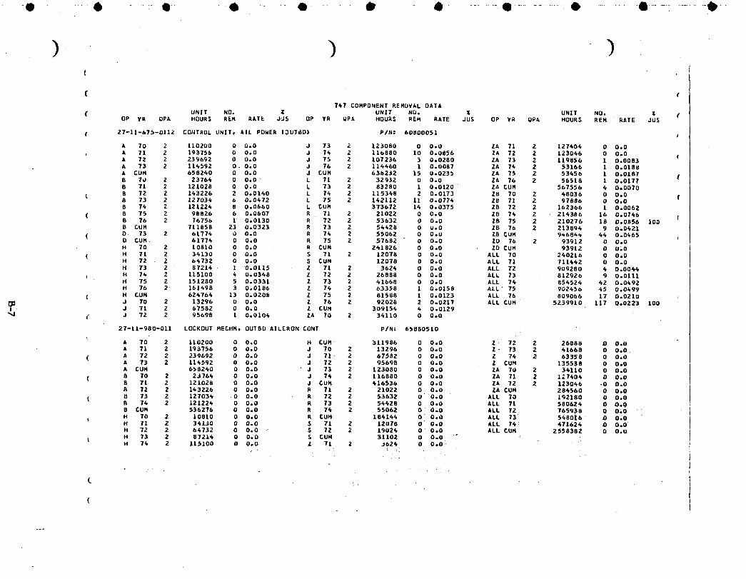
-O ..... 6 ..............l ............... • ......................• .................0 ............. Q ........... ,e .............. • ....................• ...... .........•
) ) )(
( (
7_7 COMPONENT REHUVAL DATA
( UNIT NO. Z UNIT NO. Z UNIT NO. _ (OP YR OPA HOURS REH RATE JJ$ OP YR UPA HOURS REH RATE JUS OP YR OP_ HOURS REH RATE JUS
( 27-|1-675-011_ CD_TROL UNIT. AlL POWER |3U78D| P/N: b080005| I
A 70 2 110200 0 0.0 J 73 2 123080 0 0.0 ZA Tl 2 127606 0 0.0
, A 71 2 193T56 0 0.0 J 76 2 116880 10 0.0856 ZA 72 2 123066 0 0.0 (A 72 2 239692 0 0.0 J 75 2 107236 3 0.0280 ZA 73 2 119856 1 0.0083A 73 2 116592 0 0.0 J 76 2 116460 1 0.0087 ZA 76 2 53166 1 0.0188
A GUM 658260 0 0.0 J CUN 636232 15 0.0235 ZA 75 2 53656 1 0.0187 (B ?o 2 23764 0 0.0 L 71 2 32932 0 0.0 ZA 76 2 56518 1 0.0177B 71 2 121028 0 0.0 L 73 2 83280 1 0.0120 ZA CUH 567556 6 0.0070
B 72 2 163226 2 0.0160 L 76 2 115348 2 0.0173 Z8 70 2 68036 0 0.0 (8 73 2 127036 6 0.0672 L 75 2 162112 11 0.0776 Z_ 71 2 97886 0 0.0B 76 2 121226 8 0.0660 L _UN 373672 14 0.0375 28 72 2 162366 1 0.0062
( 8 T5 2 98826 6 0.0607 R 71 2 21022 0 0.0 ZB 76 2 21_386 16 0.0746 (8 76 2 76756 1 0.0130 R 72 2 53632 0 0.0 ZB 75 2 210276 18 0.0856 100B CUH 711858 23 0.0323 R 73 2 56628 0 0.0 Z8 76 2 213894 9 0.0621
( D 73 2 61776 0 0.0 R 76 2 55062 0 O.U 28 CUH 9_686_ 46 0.0665O CUH 61776 0 0.0 R 75 2 57682 0 0.0 20 76 2 93912 0 0.0H 70 2 10810 0 0.0 R CUM 261826 0 0.0 ZD CUH 93912 0 010
( H 71 2 36130 0 0.0 S 71 Z 12078 0 0.0 ALL 70 240216 0 0.0H 72 . 2 66732 0 0.0 S CUH 12078 0 0.0 ALL 71 711662 0 0.0H 73 2 87216 1 0.0115 Z 71 2 3626 0 0.0 ALL 72 909280 4 0.0066H 7_ 2 115100 6 0.0368 Z 72 2 26888 0 0.0 ALL 73 812926 9 0.0111H 75 2 151280 5 0.0331 Z 73 2 61668 0 0.0 ALL 76 856526 42 0.0692H 76 2 ]61698 3 0.0106 Z 76 2 69358 1 0.0158 ALL: 75 902656 65 0.0499
( H CUH 626764 13 0.0208 Z 75 2 81588 1 0.0123 ALL 76 809066 17 0.0210J 70 2 13296 0 0.0 Z 76 2 92028 2 0.0217 ALL CUH 5239910 117 0.0223 100
I J TI 2 67582 0 0.0 Z CUH 309156 6 0.0129"_1 I" J 72 2 95698 1 0.0106 ZA 70 2 3_110 0 0.0
27-11-980-011 LOCKOUT NECHH, 00T80 AILERON CONT P/N: 65880510
A 70 2 110200 0 0.0 H CUM 311986 0 0.0 Z 72 2 26888 0 0.0A 71 2 193756 0 0.0 J 70 2 13296 0 0.0 Z _ 73 2 41668 0 0.0
( A 72 2 239692 0 0.0 J 71 _ 2 67582 0 0.0 Z 76 2 63358 0 0.0A 73 2 116592 0 0.0 J 72 2 95695 0 0.0 Z CUH 135538 0 0.0A CUH 668260 0 0.0 " J 73 2 123080 0 0.0 ZA 70 2 36110 0 0.0
( 0 70 2 23764 0 0.0 J 74 2 116880 0 0.0 ZA 71 2 127606 0 0.0B 71 2 121028 0 0.0 J CUN 416536 0 0.0 ZA 72 2 123066 .0 0.0B 72 2 163226 0 0.0 R 71 2 21022 0 0.0 ZA CUH 286560 0 0.0
( U 73 2 127036 0 0.0 R 72 2 53632 00.0 ALL TO 192180 0 0.0B 76 2 121226 0 0.0 R 73 2 54428 0 0.0 ALL Tl 580b26 0 0.0B CUM 536276 0 0.0 R 74 2 55062 0 0.0 ALL 72 765938 0 010 •H 70 2 10810 0 0.0 R CUH 184166 0 0.0 ALL 73 5_80|b 0 0.0H 71 2 34130 0 0.0 5 71 2 12078 0 0.0 ALL 76 _ 471626 0 0o0H 72 2 64732 0 0.0 $ 72 2 19026 0 0.0 ALL CUH 2558382 0 0.0
I H 73 2 8721_ 0 0.0 S CUH 31102 0 0.0 *" _H 76 2 115100 0 0.O Z 71 2 J626 0 0.0'
(
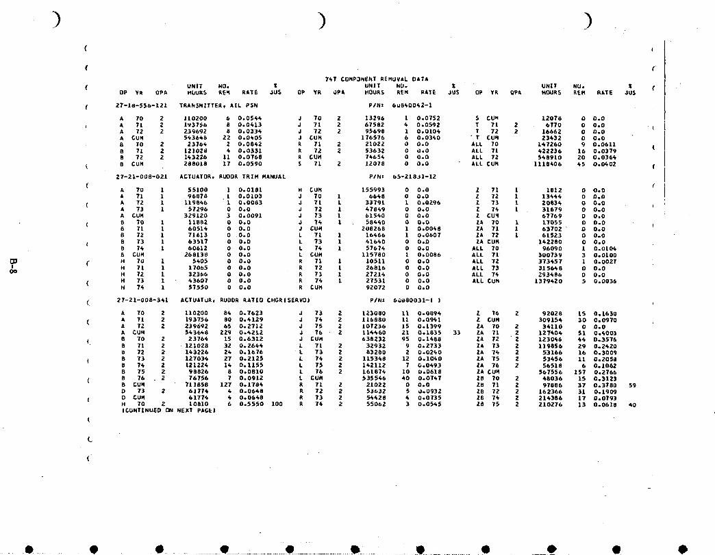
( I
( (74T CONP3NENT REMOVAL DATA
( UNIT NO. _ UNIT NU. Z UNIT NU. Z (OP YR OPA HOURS REq RATE JU$ OP YR _P& HOURS REH RATE JU$ OP YR 9PA HOURS REH RATE JU$
( 27-10-556-121 TRANSMITTER, AlL PSN P/N: 6u840042-1
A 70 2 110200 b 0.0544 J 70 2 13296 1 0.0752 S CU_ 1207_ 0 0.0
A 71 2 193756 8 0.0413 J 71 2 67582 4 0.0592 T 71 2 6770 0 000 (A 72 2 239692 8 0.0334 J 72 2 95698 1 0.0104 T 72 2 16662 0 0.0A CUR 543646 22 0.0405 J GUM 176576 6 0.0340 " T CUR 23432 O 000
8 70 2 23764 2 0.0842 R 71 2 21022 0 0.0 ALL 70 147260 9 000611 (B 71 2 I21020 4 0.0331 R 72 2 53632 0 0.0 ALL 71 422236 16 0.0379B 72 2 143226 11 0.0768 R CUH 74654 0 0.0 ALL 72 §48910 20 0.0364
8 CUR 288018 17 0.0590 S 71 2 12078 0 0,0 ALL CUR 1118406 45 0.0402 (
27-21-008-021 ACTUATOR, RUDDR TRIM MANUAL P/N: 65-218J1--12
( cA 70 1 55100 1 000181 H CUR 155993 0 0,0 Z 71 1 1812 0 OoOA 71 1 96878 .1 0.0103 J 70 1 6648 0 0.0 Z 72 1 13444 0 000
( A 72 1 119846 1 0.0083 J 71 L 33T91 1 0.0296 Z 73 1 20834 0 0.0A 73 1 57296 0 0.0 J 72 1 47849 0 0.0 Z 74 1 31679 O 0.0A CUR 329120 3 0.0091 J 73 1 61540 0 0.0 Z CU_ 67769 0 0o0
( 8 70 1 11882 0 0.0 J 74 1 58440 0 0.0 ZA TO 1 17055 0 0.08 71 1 60514 0 000 J CUR 208268 1 0.0048 ZA T1 1 63702 " 0 000B 72 1 71613 00oO L 71 I 16466 1 0.0607 ZA 72 1 61523 0 0.0
! 8 73 1 63617 0 0.0 L 73 1 41640 0 0.0 ZA GUM 142280 0 0.0B 74 1 60612 0 0.0 L 74 1 57674 0 0.0 ALL 70 96090 1 0.01048 CUR 268138 0 0.0 L GUM 115780 1 0.0086 ALL 71 300739 3 0.0100
( H 70 1 5405 0 0.0 R 71 1 10511 0 0.0 ALL 72 373457 1 0.0027I H 71 1 17065 0 0.0 R 72 1 26816 0 0.0 ALL 73 3156_8 0 000
O0 H 72 1 32366 0 0.0 R 73 1 27214 0 0.0 ALL 74 293486 0 0.0
( H 73 1 43607 0 0.0 R 74 1 27531 0 0.0 ALL CUM 1379420 5 0.0036H 74 1 57550 0 0.0 R GUN 92072 0 0.0
(i 27-21-008-341 ACTUATOR, RUDOR RATIO CHGR|SERVO| PIN: 6_880031-( )
A 70 2 110200 84 0.7623 J 73 2 123080 11 0.0894 Z 76 2 92028 15 001630
( A 71 2 193756 80 0.4129 J 74 2 116B80 11 0.0941 Z CUR 309154 30 000970A 72 2 239_92 65 0.2712 J 75 2 107236 15 0.1399 ZA TO 2 34110 0 0.0A CUR 543648 229 0.4212 J 76 2 114460 21 001835 33 ZA TI 2 127404 51 004003
(. B TO 2 23764 15 0.6312 J GUM 638232 95 0.1488 ZA 72 2 123046 44 003576B 71 2 121028 32 002644 L 71 2 32932 9 0.2733 ZA 73 2 119856 29 0.2420b 72 2 143226 24 0.1676 L 73 2 83280 2 0.0240 ZA 74 2 53166 16 0.3009
( 8 73 2 127034 27 0.2125 L 74 2 115348 12 0.1040 ZA 75 2 53456 11 00205B8 74 2 121224 14 001155 L 75 2 142112 T 0.0493 ZA 76 2 56518 6 0.1062B 75 2 98826 8 0.0810 L 76 2 161874 10 U.0618 ZA GUH 567556 157 0.2766
( B 76 2 76756 7 0.0912 L GUM 535546 40 0.0747 ZB 70 2 48036 15 0031238 CUR 711858 127 0.1784 R 71 2 21022 0 0.0 ZB 7I 2 97886 37 0.3780 59D 73 2 61774 4 0.0648 R 72 2 53632 5 000932 ZE 72 2 162366 31 001909
( D CUR 61774 4 000648 R 73 2 5_428 4 0.0735 Z8 74 2 214386 17 000793H TO 2 10810 6 005550 100 R 74 2 55062 3 0.0545 ZB 75 2 210276 13 000618 40|CONTINUED ON NEXT PAGE|
(
(..
(
,. 0 .... O , • ............ O_.............. O____...... _i..........O ..... • _ e O O,

• O ...... O .............I .........................e ....................O............... ........... O.............. O................• ...................• ............ 0--
(
((
747 COHPONENT REMOVAL DATA
UNIT NU. _ UNIT NO. Z UNIT NO. Z (( OP YR OPA HCURS REM RATE JU_ DP YR QPA HOURS REM RATE JUS OP Yk OPA HOURS KEN RATE JUS
( 27-2|-008-361 ACTUATORo RUDDR RATIQ CHGRISERVOJ |CDNTINUEDJ PIN: 60880031-| |
H 11 2 34130 3 0.0879 50 R CUM 184144 12 0o0652 Z8 76 2 213896 16 0.0768H 72 2 b_7_2 9 0,1390 29 S 71 2 12078 3 0,2484 ZE CUM 946844 129 0,1362H 73 2 8721k 15 0.1720 S CUM 12078 3 0.2484 ALL 70 240216 123 0.5120 (H 76 2 115100 19 0.1651 T 73 2 17098 1 0.0585 ALL 71 7114_2 236 0.3317H 75 2 151280 34 0.2247 30 T CUH 17098 1 0.0585 ALL 72 909280 193 0.2123H 76 2 161498 6 0.0248 Z 71 2 3624 0 O.O ALL 73 715432 94 0.1314 (H CUM 624764 90 0.1441 Z 72 2 26888 2 0.0744 ALL 74 854524 95 0.1112J 70 2 13296 3 0.2256 Z 73 2 41668 1 0.0240 ALL 75 84477_ 97 0.1148J 71 2 675UZ 2l 0.3107 Z 74 2 63358 3 0.0473 ALL 76 877028 79 0.0901 (J 72 2 95698 13 0.1358 Z 75 2 81588 9 0.1103 ALL CUM 5152696 917 0.1780 44
(27-21-404-061 QUADRANT, RUDDR CONTROL P/N: 65881213 (
( 8 70 2 23764 0 0.0 J 73 2 123080 0 0.0 Z 76 2 63358 0 0.0 /8 ?I 2 121028 0 0.0 J 74 2 116880 0 0.0 Z CUM 135538 O 0.08 72 2 1_3226 0 0.0 J CUM 416536 2 U.U048 ALL 70 37060 0 0.0
( 8 73 2 127034 0 0.0 R 73 2 54428 0 O.O ALL Tl 192234 0 O.U8 74 2 121224 0 O.O R 76 2 55062 0 0.0 ALL 72 265812 2 0.00758 CUN 536276 0 0.0 R CUM 109490 0 0.0 ALL 73 346210 0 0.0
( J 70 2 13296 0 0.0 Z 7l Z 3624 0 0.0 ALL 74 356524 0 0.0J Tl 2 67582 0 0.0 Z 72 2 26888 0 0.0 ALL CUM 1197840 2 0.0017J 72 2 95698 2 0.0209 Z 73 2 41668 O 0.0
(i_ 27-21-418-021 REGULATOR, RUODR CONT OUAD TENS P/N: SEE 27-21-404-061
{27-21-675-021 CONTRQL UNIT, RUODR POHER IPCU| P/N: 60800049
, A 70 2 110200 3 0.0272 J 75 2 107236 9 0.0839 Z CUM 309154 19 0.0615A 71 2 19375o 1 0.0052 J 76 2 114460 5 0.0437 80 ZA 70 2 34110 0 0.0A 72 2 23_692 3 0.0125 J _UN 638232 47 0.0736 ZA 71 2 127404 0 0.0A 73 2 114592 3 0.0262 L 71 2 32932 0 0.0 ZA 72 2 123046 3 0.0244A CUN 658240 10 0.0152 L 72 2 88612 0 O.O ZA 73 2 119856 9 0.07515 70 2 23764 0 0.0 L 73 2 83280 2 0,0240 ZA 74 2 53166 3 0,0564
( 8 71 2 121028 3 0.0248 L 74 2 115348 9 0.0780 ZA 75 2 53456 1 0.01878 72 2 143226 6 0.0419 L 75 2 142112 25 0.1759 ZA 76 2 56518 3 0.05318 73 2 127034 T 0.0551 L 76 2 161874 25 0,1544 24 CUM 567556 19 0.0335
( 8 74 2 121224 11 o.OgOT L CUM 624158 61 0.0977 ZB 73 2 202836 5 0.02478 75 2 98826 7 0,0708 R 71 2 21022 0 0.0 Zu 74 2 214386 19 0.0886 .8 76 2 76756 4 0.0521 R 72 2 53632 1 0.0186 28 75 2 210276 26 0.1236 90
( 8 CON 711858 38 0.0534 R 73 2 5_628 1 0.0184 ZB 76 2 213894 26 0.1216 100H 70 2 IC810 0 0.0 A 74 2 550b2 4 0.0726 28 CUN 841392 76 0.0903H 71 2 34130 1 0.0293 R 75 2 57682 1 0.0173 ZO 76 2 93912 3 0.0319
( H 72 2 o4732 0 0.0 R CUM 241826 7 0.0289 ZD CUM 93912 3 0.0319H 73 2 87214 0 0.0 S 71 2 12078 2 0o1656 ALL 70 192180 4 0.0208ICONTINUED ON NEXT PAGE)
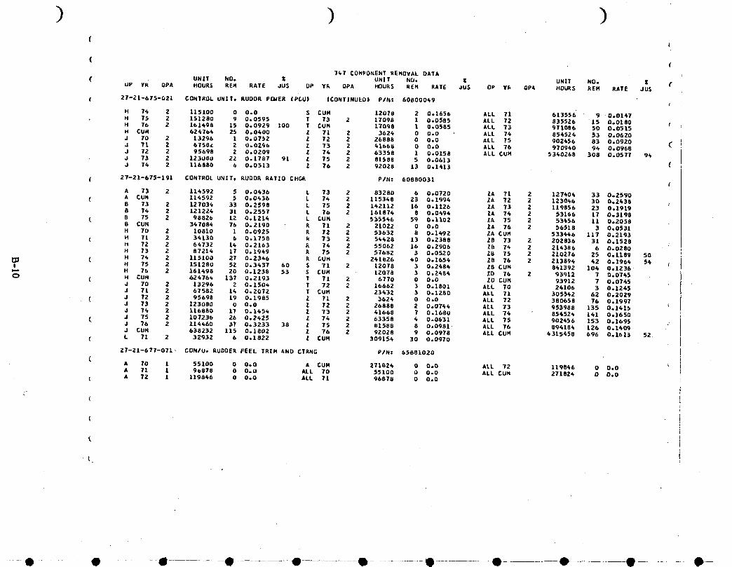
) ) )(
I
(
767 COMPONENT REMOVAL DATA
UN|T NO. • UNIT NU. • UNIT NO. • (( UP YR OPA HOURS REH RATE JUS UP YR QPA HOURS REM RATE JUS OP Y_ OPA HOURS REM RATE JUS
( 21-21-615-021 CONTROL UNITt RUOOR P(]_ER |P_U| |CONTINUED| P/N: 60B00049(
H 76 2 115100 0 0.0 S CUH 12078 2 0,1656 ALL 7! 613556 9 0.0161
H 75 2 151280 9 0.0595 T 73 2 17098 1 0,0585 ALL 72 835526 15 0.0180 tH 76 2 161498 15 0.0929 100 T CUH 17098 1 0,0585 ALL 73 971086 50 0.0515H CUH 626766 25 0,0600 Z 71 2 3626 0 0.0 ALL 74 856526 53 0,0620
J 70 2 13296 1 0.0752 Z 72 2 26888 0 0,0 ALL 75 902456 83 0,0920 (J 71 2 6758_ 2 O,OZgb 1 73 2 6166_ 0 0.0 ALL 76 970940 94 0,0968J 72 2 95698 2 0,0209 Z 76 2 63358 1 0,0158 ALL CUM 5340268 308 0.0577 9_J 73 2 123080 22 0.1787 91 Z 75 2 81588 5 0,0613J 76 2 116880 6 0.0513 Z 76 2 92028 13 0o1613 (
( 27-21-675-191 CONTROL UNZTt RUOOR RATIO CHGi_ P/N: 60880031(
A 73 2 116592 5 0,0636 L 73 2 83280 6 0,0720 ZA 71 2 127406 33 0°2590( A CON 114592 5 0,0636 L 74 2 115368 23 0,1996 ZA 72 2 123046 30 0,2638
B 73 2 127036 33 0,2598 L 75 2 162112 16 0,1126 ZA 73 2 119856 23 0,19198 76 2 121226 31 0,2557 L 76 2 16187.6 8 0,0494 ZA 74 2 53166 17 0,3198
( 8 75 2 98826 12 0,1216 L CUH 535546 59 0,1102 ZA 75 2 53456 11 0,20588 CON 367086 76 0,2190 R 71 2 21022 0 0,0 ZA 76 2 56518 3 0.0531H 70 2 10810 1 0.0925 R 72 2 53632 8 0,1492 ZA CUM 533666 117 0,2193
( H 71 2 36130 b 0.1758 R 73 2 56628 13 0,2388 ZB 73 2 202836 31 0,1528H 72 2 64732 14 0.2163 _ 76 2 55062 16 0,2906 28 76 2 214386 6 0°0280H 73 2 87216 17 0.1969 R 75 2 57682 3 0-0520 28 75 2 210276 25 0,1189 50
[_ ( H 74 2 115100 27 0.2366 R £UH 241826 60 0,1656 ZB 76 2 213896 42 0,1966 56I H 75 2 151280 52 0.3437 60 S 71 2 12078 3 0,2484 28 CUN 861392 106 0,1236
H 76 2 161698 20 0.1238 53 S CUN 12078 3 0.2684 ZD 76 2 93912 7 0,0765O ( H CUH 62476_ 137 0.2193 T 71 2 6770 0 0.0 ZO CUN 93912 7 0.0745 •
J 70 2 13296 2 0o150_ T 72 2 16662 3 0,1801 ALL 70 24106 3 0,1245J 71 2 67582 16 0.2072 T CUH 23432 3 0,1280 ALL 71 305562 62 0,2029
( J 72 2 95698 19 0.1985 Z 71 2 3626 0 0.0 ALL 72 380658 76 0,1997J 73 2 123080 0 0.0 Z 72 2 26888 2 0,0766 ALL 73 953988 135 0,1_15J 74 2 116880 17 0.1654 Z 73 2 41668 7 0.1680 ALL 74 85_526 141 0,1650
( J 75 2 107236 26 0,2625 Z 74 2 63358 4 0,0631 ALL 75 902456 153 0,1695 .J 76 2 116660 37 0,3233 38 Z 75 2 _1588 8 0,0981 ALL 76 894186 L26 0.1409J CUH 638232 115 0,1802 Z 76 2 92028 9 0.0978 ALL CUM 6315458 696 0,1613 52
( L 71 2 32932 6 0.1822 Z CUM 309156 30 0.0970
27-21-677-071_ CON/U, RUDDER FEEL TRIM _ND CTRNG P/N: 65881020(
A 10 1 55100 0 0°0 A CUH 271824 0 0,0 ALL 72 119846 0 0,0A 71 1 9_878 0 0,0 ALL TO 55100 0 0.0 ALL CUM 271824 0 0,0
I A 72 1 119866 0 0,0 ALL 71 96870 0 0o0
r
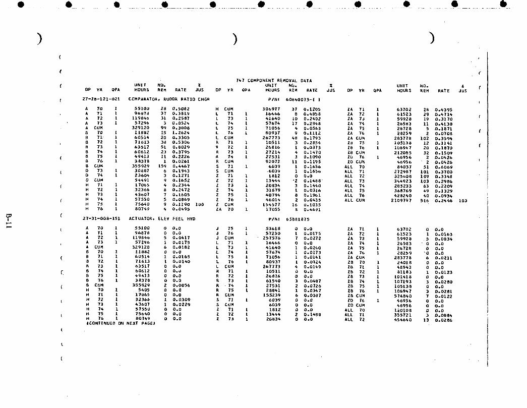
,O ...... O , t .......... e ............ • ..............• .......... • ....... • ..................O_................• ............ O.
) ) )(
f (
767 COMPONENT REHDVAL DATA
( UNIT NUo Z UNXT N_. Z UNIT NO. _ (DP YR QPA HDUR$ REH RATE JUS OP YR QPA H_UR$ REM RATE JUS OP YR QPA HOURS REH RATE JUS
( 27-28-121-O21 CCHPARATOR, RUDDR RAT|D CHGR PIN: 608&O073-1 I f
A 70 ! 55100 28 0.5082 H CUH 306977 37 0.1205 ZA Tl 1 63702 28 0°4395
A 71 l 96_7d 37 0.3819 L 71 1 16466 8 0.6858 ZA 72 1 61523 29 0.6716 fA 72 X 119866 31 0.2587 L 73 1 41660 10 0.2602 ZA 7_ 1 59928 19 0.3170A 73 1 57296 3 0.0526 L 76 1 57676 17 0.2968 ZA 76 1 26583 11 0.4138
A CUH 329120 99 0.3008 L 75 1 71056 4 0.0563 ZA 75 1 26728 5 0.1871 (B 70 I 11882 15 L.2626 L 76 1 80937 9 0.1112 ZA 76 1 28259 2 0o07088 71 1 60514 20 0.3305 L CUH 267773 68 0.1793 ZA CUM 283778 102 0°3594
8 72 1 71613 38 0.5306 R 71 1 10511 3 0.2856 ZO 75 1 105138 12 O.1141 (B 73 1 63517 51 0°8029 R 72 1 26816 1 0.0373 Z8 76 1 106967 20 0.18708 76 1 60612 23 0.3795 R 73 1 27214 4 0.1670 Z8 CUH 212085 32 0.1509
( 8 75 1 69613 11 0.2226 R 76 1 27531 3 0.1090 ZU 76 1 66956 2 0.0626 I8 76 1 38378 1 0.0261 R CUH 92072 11 0.1195 20 CUM 66956 2 0°0626B CUH 355929 159 0.6667 S 71 1 6039 1 0.1656 ALL 70 84037 51 0.6069
( D 73 1 30687 6 0.1963 S CUM 6039 1 0.1656 ALL 71 272987 101 0.37000 76 1 23606 3 0.1271 Z 71 1 1812 0 0.0 ALL 72 325008 109 0.33680 CUM 56491 9 0.1652 Z 72 1 13644 "2 0.1688 ALL 73 366923 103 0.2986H 71 1 17065 6 0.2366 Z 73 1 20836 3 0.1660 ALL 76 285233 63 0.2209H 72 1 32366 8 0.2672 Z 76 1 31679 1 0.0316 ALL 75 368769 69 0.1329H 73 1 63607 7 0.1605 Z 75 1 60794 8 0.1961 ALL 76 628260 60 0.0936H 74 1 57550 5 0.0869 Z 76 1 66016 2 0.0435 ALL CUH 2109797 516 0.2646 103H 75 1 75640 9 O.1190 100 Z CUH 156577 16 0.1035H 76 1 80769 6 0.0695 ZA 70 1 17055 8 0.6691
I 27-31-008-151 ACTUATOR, ELEV FEEL HYD PIN: 65881875
( A 70 1 55100 0 0.0 J 75 1 53618 0 0.0 ZA 71 1 63702 0 0.0A 71 1 96878 0 0,0 J 76 1 57230 1 0.0175 ZA 72 1 61523 1 0o0163A 72 1 119866 5 0.0417 J CUH 257576 7 0.0272 ZA 73 1 59928 5 0.0836A 73 1 57296 1 0.0175 L 71 1 16466 0 0.0 ZA 76 1 26583 0 0o0A CUH 329120 6 0.0182 L 73 1 61660 1 0.0260 ZA 75 1 26728 0 0.08 70 1 11882 0 0.0 L 76 1 57674 1 0.0173 ZA 76 1 28259 "0 0.0
( 8 71 1 60516 1 0.0165 L 75 1 71056 1 0.0161 ZA CUM 283778 6 0.0211B 72 1 71613 1 0.0160 L 70 1 80937 1 0.0126 ZB 70 1 24018 0 0.0B 73 1 63517 0 0.0 L CUR 267773 4 0.0169 ZB 71 1 68943 0 O.0
_ B 76 1 60612 0 0.0 R 71 1 10511 0 0.0 ZB 72 1 81183 1 0.01238 75 1 69613 0 0.0 R 72 1 26816 0 0.0 Z8 73 1 101418 0 0.08 76 1 38378 0 0.0 R 73 1 61540 3 0.0687 ZB 76 L 107193 3 0.0280
( 8 CUH 355929 2 0.0056 R 76 1 27531 2 0.0726 ZB 75 1 105138 0 0.0H 70 1 5605 0 0.0 R 75 1 28861 1 0.0367 ZB 76 1 106967 3 0°0281H 71 1 17065 0 0.0 R [UM 155239 6 0.0387 Z0 CUH 576860 7 0.0122
( H 72 1 32366 1 0.0309 $ 71 1 6039 0 0.0 Z0 76 1 66956 0 0.0H 73 1 43607 1 0.0229 S CUH 6039 0 0.0 Z0 CUM 66956 0 0.0H 74 1 57550 0 0o0 Z 71 1 1812 0 0.0 ALL 70 110108 0 0.0
I H 75 1 75660 0 0.0 Z 72 1 13666 2 0.1488 ALL 71 355721 3 0.0086H 76 1 80749 0 0.0 Z 73 1 20834 0 0o0 ALL 72 456660 13 0.0286ICQNT|NUED 0_1 NEXT PAGE)
(

) )(
(
(
i767 COMPONENT RtMOVAL DATA
UNIT NU. _ UNIT Nb. _ UNIT NO. Z t( OP YR OPA HOURS REN RATE JUS OP VR QPA HuURS RtM RATE JUS OP yR UPA HOURS REM RATE JUS ,
f 27-31-U08-[51 ACTUATUk. ELEV FEEL HYD |CONTINUEDI PIN: 65881875
H CUH 312382 2 0.0064 Z 74 1 31679 0 o.O ALL 73 649760 11 0.0245J 70 1 6648 0 0.0 Z 75 1 ¢079¢ 1 0.02¢5 ALL 74 627262 8 0o0187J 71 1 33791 Z 0.0592 Z 76 1 46016 3 0.0652 ALL 75 451228 3 0.0066J 72 1 47849 2 0.0418 Z CUH 154577 6 0.0388 ALL 76 485470 8 0.0165J 74 1 58440- Z 0.0342 ZA 70 E 17055 0 0.0 ALL CUH 2746209 66 0.0168 !
27-31-122-011 COLUMN, ELEV CONT P/N: SEE 27-00-122-021
f27-31-130-021 COHFUIEKo ELEV FEEL PIN: 60B00055
(A 70 1 55100 0 0.0 J 76 1 57230 6 0.1048 83 ZA TO 1 17055 0 0.0A 71 1 96878 7 0.0723 J CUH 319116 11 0.0345 ZA 71 1 63702 1 0.0157
( A 72 1 119840 11 0.0918 L 71 1 16466 0 0.0 ZA 72 1 61523 7 0.1138A £UH 271826 18 0.0662 L 73 1 41660 1 0.0240 ZA 73 1 59928 7 0o1168B 70 1 11882 • 1 0.0862 L 74 1 57674 1 0.0173 ZA 74 1 26583 3 0.112_
Tl 1 60514 2 0.0331 L 75 1 71056 5 0.0704, ZA 75 1 26728 6 0.1697( _ 72 1 71613 1 0.0140 L 76 1 80937 4 0.0494 ZA 76 1 28259 3 0.1062
B 73 1 63517 4 0.0630 L CUN 267773 11 0._411 ZA CUH 28377_ 25 0.0881( 8 74 1 60612 5 0.0825 R 71 1 10511 0 0.0 28 70 1 26018 1 0.0_16
B 75 1 - 49413 1 0.0202 R 72 1 26816 0 0.0 L8 71 1 68943 6 0.16350 76 1 38378 6 0.1563 R 73 1 27214 1 0.0367 ZB 72 1 81183 5 0.0616 100
_3 ( 8 CUH 355929 20 0.0562 R 76 1 27531 1 U.0363 Z8 73 1 101418 5 0.0493I H 70 1 5405 0 0.0 R 75 1 28841 1 0.0347 28 74 1 107193 16 0.1306
H 71 1 17065 0 0.0 R CUM 120913 3 0.0248 Z8 75 1 105138 6 0.0571 100I%) _ H 72 1 32366 3 0.0927 S 71 1 6039 0 0.0 Zb 76 1 106947 16 0.1496 75
H 73 1 63607 2 0.0459 S CUN 6039 0 0°0 Z8 CUH 574860 55 0.0957H 74 1 57550 3 0.0521 T 71 1 3385 1 0.2956 ZD 76 1 66956 0 0.0
( H 75 1 75660 2 0.0264 T 72 1 8331 1 0o1200 ZD CUM 66956 0 D,OH 76 1 80749 5 0.0619 75 T CUM 11716 Z 0.1707 ALL 70 120108 Z 0.0167H CUH 312382 15 0.0680 Z 71 1 1812 0 0.0 ALL 71 359106 19 0,0529J 70 1 6668 0 0.0 Z 72 1 13466 0 0.0 ALL 72 462971 29 0,0626
( J 71 1 33791 0 0.0 Z 73 1 20834 1 0.0480 ALL 73 619698 21 0,0503J 72 1 67849 1 0.0209 Z 74 1 31679 2 0.0631 ALL 74 627262 32 0,0769
( J 73 1 61540 0 0.0 Z 75 1 40794 1 0.0245 ALL 75 451228 21 0o046_J 74 1 58660 3 0.0513 Z 76 1 46014 7 0o1521 ALL 76 485470 67 0.0S68J 75 1 53618 1 0.0187 Z CUH 154577 11 0.0712 ALL CUH _725843 171 0.0627 8_
27-31-404-091 OUAORANT. ELEV CONTROL P/N= 65880310
(
J 70 1 6668 0 0.0 R 72 1 26816 0 0°0 ZA 71 1 63702 O 0°0J 71 1 33791 0 0.0 R 73 1 27214 0 0.0 ZA 72 1 61523 0 0o0
L J 72 1 67849 0 0.0 R 74 1 27531 0 U°O ZA 73 L 599Z8 0 0o0J 73 1 61540 0 0o0 R CUN 92072 0 0°0 ZA 76 1 26583 0 0o0 fJ 76 1 58660 0 0.0 5 71 [ 6039 O 0o0 ZA CUN 228191 0 0.0
! (CONTINUEO ON NEXT P&GEI I!I
i
O • • ...............O • .................0 ............. • ............... • ........... • .......... • .................0-
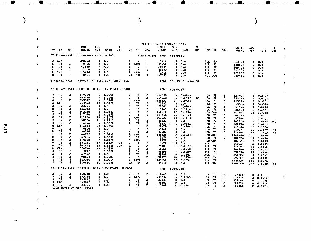
-.-O - • .............• .................0 ...................• ....................dl!, ......... 4 ......... 0 ................0 ............. • ...................0.-
(
(
747 COHPONENT REMOVAL DATA
UNIT NU. Z UNIT NO. _ UNIT NO. _OP ¥R UPA HOURS REH RATE JJS OP YR UPA HOURS REH RATE JUS OP YR UP_ HOURS REH RATE JUS
( 27-31-404-091 OUADRANT, ELEV CONTROL (CONTINUED) P/N= 65880310 I
J CUH 208268 O O.O S TZ L v512 0 0.0 ALL 70 23703 0 O.Oe L TI 1 1o_6_ 0 O.O S CUM 15551 0 0.0 ALL T1 130509 0 O.O
L 73 1 41660 0 DoO Z 73 1 20834 b O.O ALL 72 145700 O 0.0.L 74 1 57674 0 0.0 Z 76 1 31679 0 O.O ALL 73 211156 0 0.0
L CUH 115760 0 O.O Z CUH 52513 0 0.0 ALL 74 201907 D 0.0 IR 71 1 10511 0 O.O ZA 70 1 17055 0 O.O ALL CUH 712975 O O.O
27-31-418-011 REGULATOR, ELEV CONT OUAU TENS PIN: SEE 27-31--_04-U91 (
( 27-31-675-0511 CONTEOL UNIT, ELEV POWER (INBD) P/N: 60800067
A 70 2 110200 1 0.0091 J 75 2 107236 5 0.0466 ZA 71 2 127604 5 0.0392( A 71 2 193756 4 0.0206 J 76 2 114460 5 0.0437 80 ZA 72 2 123046 6 0.0325
A 72 Z 239692 5 0.0209 J CUH 638232 27 0.0423 ZA 73 2 119856 3 0.0250A CUH 543648 10 0.0186 L 71 2 32932 0 O.O ZA 74 2 53166 2 0.03768 70 2 23766 0 0.0 L 73 2 83280 3 0;0360 ZA 75 2 53456 4 0.0748B 71 2 121028 O 0.0 L 76 2 115348 14 0.1214 ZA 76 2 56518 3 0.05318 72 2 143226 2 0.0140 L 75 2 142112 17 0.1196 ZA CUH 567556 21 0.0370
( B 73 2 12703; 2 0.0157 L 76 6 323748 44 0.1359 ZD 70 2 48036 0 0.08 74 2 121226 13 0_1072 L CUH 697420 78 0.1118 28 71 2 97886 2 0.0204B 75 2 98826 11 0.1113 R 71 2 21022 0 O.O ZB 72 2 162366 9 0.0554 1008 76 2 76756 4 0.0521 R 72 2 53632 • 1 0.0186 ZB 73 2 202836 4 0.O197
( 8 CUH 711858 32 0.0650 R 73 2 56428 1 0.O186 28 74 2 216386 22 O.1026I_ H 70 2 10810 0 O.O R 74 2 55062 0 0.0 28 75 2 210276 30 0.1427 90t._ ( H 71 2 34130 0 O.O R 75 2 57682 0 0.0 28 76 2 213894 33 0.1543 96
H 72 2 66732 3 0.0663 R CUH 241826 2 0.U083 ZB CUM 1169680 100 0.0870H 73 2 87216 6 0.0688 S 71 2 12078 O O.O ZD 76 4 187824 9 0.0479H 76 2 115100 2 0.0174 S CUH 12078 0 0.0 ZD CUH 187826 9 0.0679H 75 2 151280 17 0.1124 90 Z 71 2 3626 0 0.0 ALL 70 240216 2 0.0083H 76 2 161498 18 0.1115 lOO Z 72 2 26888 1 0.0372 ALL 71 711662 11 0.0155
( H CUR 624766 46 0.0736 Z 73 2 41668 1 0.0260 ALL 72 909280 27 0.0297J 70 2 13296 1 0.0752 Z 76 2 63358 5 0.0789 ALL 73 839396 23 0.0274J 71 2 67582 0 0.0 Z 75 2 81588 9 0.1103 ALL 74 854524 69 0.0807
( J 72 2 95698 2 0.0209 Z 76 2 92028 16 0.1739 ALL 75 902456 93 0.1031J 73 2 123080 3 0.0264 Z CUN 309154 32 0.1035 ALL 76 1226726 132 0.1076J 74 2 116880 11 0.0941 ZA 70 2 34110 O 0.0 ALL CUH 56860_0 357 0.0628 93
(27-31-675-0512 CONTROL UNIT, ELEV POWER (OUTBD) PIN: 60800048
( A 70 2 110200 0 0.0 J 16 2 116460 O O.O ZA TO 2 34110 O 0.0A 71 2 193756 0 0.0 J CUH 638232 6 0.0063 ZA 71 2 127404 2 0.0157A 72 2 23_692 0 O.O L 71 2 32932 0 0.0 ZA 72 2 123046 5 0.0_06A CUM 543648 O O.O L 73 2 83280 O U-O ZA 73 2 119856 4 0.0336B 70 2 23764 0 O.O L 74 2 115348 4 0.0347 ZA 74 2 53166 2 0.0376(CONTINUED ON NEXT PAGE]
(
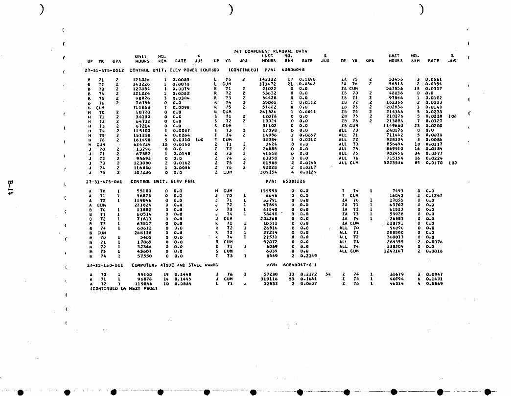
( 4
( I
767 CUNPUNENT REHOVAL DATA
uhlT NO. _ UNiT NO. _ UHIT NOD _ f.OP YR OPA HOURS REH RATE JU$ UP ¥R UPA HOURS REN RATE JUS OP YR UPA HOURS REH RATE JU$
( 27-31-675-0512 CONTROL uNiTt ELEV POWER tOUT_Di ICONTiNUEOi PIN= 60500048
8 71 2 121026 1 0.0083 L 75 2 162112 17 0.1196 ZA 75 2 53656 3 0.05615 72 2 163226 1 0.0070 L CUR 373672 21 0.0562 ZA 76 2 56518 2 0.0356 i8 73 2 127036 1 0.0079 R 71 2 21022 0 O.O ZA CUH 567556 18 0.03178 74 2 121226 1 O.0OB2 k 72 2 53632 0 O.O Z8 70 2 68036 0 0.O
B 75 2 98826 3 0°0304 R 73 2 56628 0 U.O 28 71 2 97886 1 0,0102 (B 76 2 76756 0 0.0 R 76 2 55062 1 0.O182 Z8 72 2 1623b6 2 0.0123B CUH 711858 7 0.0098 R 75 2 57682 O 0.U ZB 73 2 202836 3 0,0148
H TO 2 10770 O 0.O R CUH 241826 1 0.0041 Z8 76 2 216386 5 0.0233H 71 2 36130 0 0.0 S 71 2 12078 0 0.0 Z8 75 2 210270 5 0.0238 100H 72 2 66732 0 0.0 S 72 2 19026 0 0.0 Zb 76 2 213894 7 0.0327
( H 73 2 87216 0 O.O S CUH 31102 0 0.0 Z8 CUH 1169680 23 0.0200H 76 2 115100 1 0.0087 T 73 2 17098 O O.U ALL 70 260176 0 0.0H 75 2 151280 _ 0.02o6 T 74 2 16986 1 0.0667 ALL 71 711662 5 0.0070
f H 76 2 16/498 5 0.0310 1_0 T CUM 32086 1 0.0312 ALL 72 928304 8 0.0086H CUH 626724 10 0.0160 Z 71 2 3624 0 O.U ALL 73 856494 10 0.0117J 70 2 13296 0 0.0 Z 72 2 26888 0 0.0 ALL 74 869510 16 0.0186
( J 71 2 67582 1 0.0168 Z 73 2 61668 0 0.0 ALL 75 902656 36 0.0377J 72 2 95698 0 0.0 2 76 2 63358 0 0.0 ALL 76 715156 16 0.0226J 73 2 123080 2 0.0162 Z 75 2 81588 2 0.0245 ALL CUM 5223536 8_ 0.0170 100
( J 74 2 116880 1 0.0086 Z 76 2 92028 2 0.0217J 75 2 107236 0 0.0 Z CUM 309156 6 O.O129
1_3 27-31-675-061 CONTROL UNITt ELEV FEEL PIN: 65881226t
A 70 1 55100 0 0.0 H CUM 155993 0 O.O T 7_ 1 7493 0 0.0( A 71 1 96878 0 0.0 J 70 1 6668 0 0o0 T CUH 160_2 2 0.1247A 72 1 119866 0 0.0 J 71 1 33791 0 O.O ZA 70 1 17055 O O.O
A CUM 271824 0 0.0 J 72 1 47849 0 O.O ZA 71 1 63702 D 0.0
( 8 70 1 11882 0 0.0 J 73 1 61560 0 0.0 ZA 72 1 61523 O 0.08 71 1 6051_ 0 0.0 J 74 1 58660 " O 0.0 ZA 73 1 59928 0 0.08 72 1 71613 0 0.0 J CUM 208268 0 0.0 ZA 74 1 26583 0 O.O
( B 73 1 63517 O 0.0 R 71 1 10511 0 O.O ZA CU_ 228791 O O.O8 74 1 60012 0 O.O R 72 1 26816 0 0.0 ALL 70 96090 0 0.08 CUN 268138 0 0.0 R 73 1 27216 0 0.0 ALL 71 288500 0 0.0
( H 70 1 5605 0 0.0 R 74 1 27531 0 O.O ALL 72 360013 0 O.OH 71 1 17065 O 0.0 R CUM 92072 O ODD ALL 73 266355 2 0.0076H 72 1 32366 0 0.0 S 71 1 6039 0 0.0 ALL 76 238209 0 0.0
( H 73 1 43607 0 0°0 S CUN 0039 0 0.0 ALL CUH 1267167 2 0.0016H 74 1 57550 O 0.0 T 73 1 8569 2 0.2339
( 27-32-130-011 Cf_PUTER, ATUDE AND STALL WARNG PIN: 60860067-( i
A 70 1 55100 19 0.3668 J 76 1 57230 13 0.2272 54 Z 76 1 31679 3 0.0967
i A 71 1 96878 16 0.1465 J CUH 319110 53 0.1661 Z 75 1 40796 6 0.1471A 72 1 119846 10 0.0836 L 71 _ 32932 2 O.ObO? Z 76 1 _6016 6 0.0869|CONTINUED ON NExT PAGE|
(
(
- t! -" e .... • ...................e • e ill ill- e • 0--
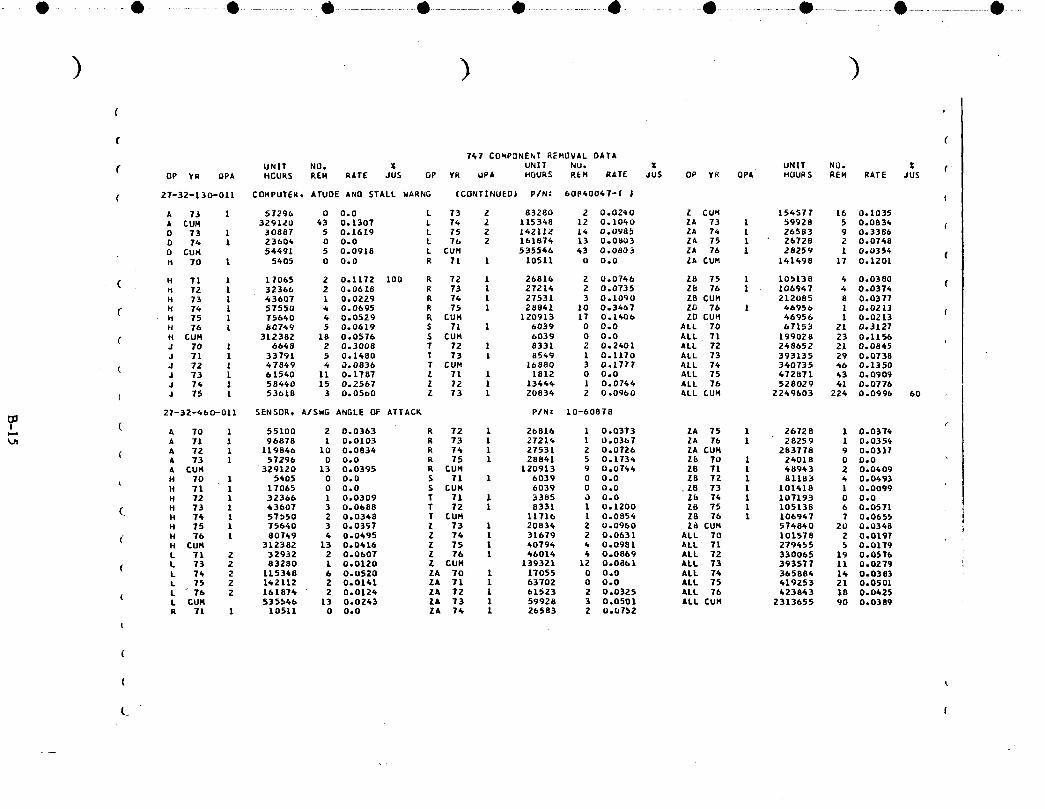
O- -0 ............ e ...................e ....................e .................• ..................• .......... • ................e ....................• ....................0 ......
f (7_1 COmPONEnT REHOVAL OATA
UNIT NO. _ UN|T NU. X UNIT NO. Z (( OP YR QPA HCURS REH RATE JUS OP ¥R QPA HOURS REH RATE JUS OP YK QPA HOURS REM RATE JUS
( 27-32-130-011 CONPUTER, ATUDE ANO STALL WARNG [CONTINUED| P/N: 60B4004T-( J {
A 73 1 57296 0 0.0 L 73 2 83280 2 0.02¢0 Z CUM 156577 16 0.1035A CUH 329120 63 0.1307 L 74 2 115348 12 0.1060 ZA 73 1 59928 5 0.0836 (D 73 1 30887 5 0.1619 L 75 2 142112 16 0.0985 ZA 7_ 1 26583 9 0.3386D 74 1 23606 0 0.0 L 76 2 161876 13 0.0803 ZA 75 1 26728 2 0.0768
0 CUH 54491 5 0.0918 L CUM 535546 63 0,0803 ZA 76 1 28259 1 0,0354 (H 70 I 5605 0 0.0 R 71 I 10511 0 0.0 ZA CU_ 161498 IT 0.1201
( H 71 1 17065 2 0.1172 100 R 72 1 26816 2 0.0766 28 75 1 105138 6 0.0380 (H 72 l 32366 2 0.0618 R 73 1 27216 2 0.0735 ZB 76 1 106947 4 0,037_H 73 l 43607 1 0.0229 R 74 1 27531 3 0.1090 ZB CUH 212085 8 0.0377
N 74 1 57550 4 0.0695 R 75 1 28861 10 0.3667 ZD 76 1 46956 1 0.0213 fH 75 1 75660 4 0.0529 R CUH 120913 IT 0.1406 ZD CUH 66956 1 0.0213H 76 1 80769 5 0.0619 S 71 1 6039 0 0.0 ALL 70 67153 21 0.3127
( H CUN 312382 18 0.0576 S CUH 6039 0 0.0 ALL 71 199028 23 0.1156J 70 1 6668 2 0.3008 T 72 1 8331 2 0.2401 ALL 72 268652 21 0.0845J 71 1 33791 5 0.1680 T 73 1 8569 1 0.1170 ALL 73 393135 29 0.0738
( J 72 1 47869 4 0.0836 T CUM 16880 3 0.1777 ALL 76 340735 46 0.1350J 73 1 61560 11 0.1787 Z 71 1 1812 0 0.0 ALL 75 672871 63 0.0909J 74 1 584_0 15 0.2567 Z 72 1 13666 1 0.0766 ALL 76 528029 41 0.0776
( J 75 1 53618 3 0.05o0 Z 73 1 20836 2 0.0960 ALL CUN 2249603 224 0.0996 60
27-32-660-011 SENSOR, A/$WG ANGLE OF ATTACK P/N: 10-60878
! ( A 70 1 55100 2 0.0363 R 72 1 26816 1 0.0373 ZA 75 1 26728 1 0.0376A 71 1 96878 1 0.0103 R 73 1 27216 1 0.0367 ZA 76 1 28259 1 0o035_
( A 72 I 119866 10 0.0836 R 74 1 27531 2 0.0726 ZA CUH 283778 9 0.0317A 73 1 57296 0 0.0 R 75 1 28861 5 0.1736 Zb 70 1 26018 0 0.0A CUN 329120 13 0.0395 R £UM 120913 9 0.0746 ZB 71 1 48963 2 0.0609H 70 1 5605 0 0.0 S 71 1 6039 0 0.0 ZB 72 1 81183 6 0.0693H 71 1 17065 0 0.0 $ CUH 6039 0 0.0 ZB 73 1 101418 1 0.0099H 72 1 32366 1 0.0309 T 71 1 3385 0 0.0 Zb 76 1 107193 0 0.0
_ H 73 1 63607 3 0.0688 T 72 1 8331 1 0.1200 ZB 75 1 105138 6 0.0571 ;H 76 1 57b§0 2 0.0368 T CUH 11716 1 0.0856 Z8 76 1 106947 7 0.0655 iH 75 1 75660 3 0.03S7 Z 73 1 20836 2 0.0960 Z8 CUN 576860 20 0.0368 iH 76 1 80749 4 0.0495 Z 74 1 31679 2 0.0631 ALL 70 101578 2 0.0197
( H CUH 312382 13 0.0616 Z 75 1 6079_ 6 0.0981 ALL Tl 279455 5 0.0179L 71 2 32932 2 0.0607 Z 76 1 46016 6 0.0869 ALL 72 330065 19 0.0576
( L 73 2 83280 1 0.0120 Z CUN 139321 12 0.0861 ALL 73 393577 11 0.0279L 74 2 115368 6 0.0520 ZA 70 1 17055 0 0.0 ALL 76 365884 16 0.0383L 75 2 142112 2 0.0141 ZA 71 1 63702 0 0.0 ALL 75 619253 21 0.0501
( L _ 76 2 161876 2 0.0124 ZA 72 1 61523 2 0.0325 ALL 76 423843 18 0.0425L CUH 535566 13 0.0243 ZA 73 1 59928 3 0.0501 ALL CUM 2313655 90 0.0389R 71 1 10511 0 0.0 ZA 76 1 26583 2 0.U752
I
. --

((
( t747 COMPONENT REMOVAL DATA
UHIT NO. _ UNIT NU. Z UNIT NO. Z (( OP ¥R UPA HOURS REH RATE JUS OP ¥R UPA HOURS REM RATE JUS OP Y_ QPA HOURS REM RATE JUS
( 27-32-471-01[ SHAKER, ATUD_ISTALL _ARt|G CNTCL P/N: C-07202
A 70 2 110200 O 0,0 R 71 1 10511 0 O,O ZA 73 1 59928 0 0,0A 71 2 193756 3 0,0155 _ 72 1 26816 0 0,U ZA 74 1 26583 0 0,0 rA 72 2 239692 2 0,0083 R 73 1 27214 0 O,O ZA CUH 228791 1 0,0044A 73 2 116592 0 0,0 R 76 1 27531 0 O,O 28 73 1 101418 1 0,0U99A CU_ 658240 5 0,0076 R :UH 92072 0 U,O 28 CUM 10141_ 1 0,0099
' D 74 1 23604 1 0,0424 Z 73 1 20834 O O,O ALL 70 127255 O 0,00 CUM 23604 1 0,0426 Z 74 1 31679 1 0,0316 ALL 71 300901 4 0,0133
L 71 2 32932 0 0,0 Z CUN 52513 1 0,0190 ALL 72 328031 2 0,0061 (L 73 2 83280 0 0,0 ZA 70 1 17055 O 0,0 ALL 73 607266 L 0,0025L 76 2 115348 0 0,0 ZA 71 1 63702 1 0,0157 ALL 74 224745 2 0,0089
( L CUM 23156U U 0,0 ZA 72 1 61523 O 0,0 ALL CUM 1388198 9 0,0065 t_
27-35-130-041 CCHPUTER,DVER-ROTN WARNG P/N: 60_0047-( ) I
( A 70 1 55100 6 0,1089 L 73 1 61640 1 0.02_0 Z £UH 156577 13 0,0841A 71 1 96878 11 0,1135 L 74 1 5767_ T D,1216 ZATO L 17055 O 0,0
( A 72 1 119846 12 0,1001 L 75 1 71056 2 0,0281 ZA 71 1 63702 3 0,0471A 73 1 57296 3 0,0524 L 76 1 80937 1 0,012_ ZA 72 1 6_523 fl 0,1300A CUH 329120 32 0,0972 L £UN 267773 11 0,0611 ZA 73 1 59928 11 0,1838
D 73 1 30887 4 0,1295 R 71 1 10511 1 0,0951 ZA 74 1 26583 O 0,0D 76 1 23604 0 0,0 R 72 L 26816 3 0,1119 ZA 75 1 26728 1 0,0374D CUM 54491 4 0.0734 R 73 1 27214 5 0.1837 ZA 76 1 28259 1 0.0354
_3 H 71 1 17065 1 0,0586 R 76 1 27531 1 0,0363 ZA CUN 283778 24 0,0846( H 7Z 1 32366 2 0,0618 R 75 1 28841 3 0,1060 ZB 75 1 105138 6 0,05710% H 73 1 43607 1 0,0229 R CUM 120913 13 0,1075 15 76 1 106967 6 0,0376
{ H 74 1 57550 5 0,0869 S 71 1 6039 1 0,1656 28 CUN 212085 10 0,0472 .H 75 1 75640 8 0,1058 TO S CUM 6039 1 0,1656 Z0 76 1 6b956 1 0o0213H 76 1 80769 4 0,0495 75 T 71 1 3385 O 0,0 ZD CUM 46956 1 0,0213
( H CUH 306977 21 0,0686 T 72 1 8331 1 0,1200 ALL 70 78803 9 0,1162J TO 1 6668 3 0,4513 T 73 1 8549 O U,O ALL 71 269649 22 0,0881J 71 1 33791 5 0,1680 7 74 1 7493 2 0,2609 ALL 72 310175 30 0,0967J 72 1 47849 3 0,0627 1 CUM 2775U 3 0,1081 ALl 73 "351495 42 0,1195J 73 1 61540 12 0,1950 Z 71 1 1812 O 0,0 ALL 74 290554 25 0,086DJ 74 1 58440 8 0,1369 Z 72 1 13444 1 0,0744 ALL 75 401815 30 0,0767
d 75 1 53618 7 0,1306 Z 73 1 20836 5 0,2600 ALL 76 647092 18 0,0403J 76 1 57230 5 0,0876 40 Z 74 1 31679 2 0,0631 ALL CUM 2129583 176 0,0826 62J CU_ 3L9116 43 0,1347 Z 75 [ 40794 3 0,0735
( L 71 1 16466 O ODD Z ?b 1 66014 2 0°0635
27..-41--006--011 STAB TRIM AUX CONTL ACCUMULATOR P/N: 65880196
( B 73 1 63517 3 0,0472 Z 76 1 31679 O 0,0 ZA CUM 141498 9 0°0636B £UH 63517 3 0,0472 Z 75 1 40794 0 0,0 ZB 75 1 105138 0 0,0
( L 73 1 61640 O 0,0 2 76 1 66014 O 0,0 28 CUH 105138 0 0,0L 74 1 57676 0 0°0 Z CUM 139321 O 0,0 ALL 73 185919 5 0,0269ICONT|NUEO I_i NEXT PA_E|
- " O ..... qP ....O..................O O.............. O...................O............... O O O 0--
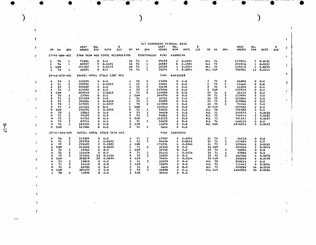
• 4 0 - i ........... i ........... e ...... • .......4.......... i ................• ...............•
( (
747 COHPONENT REMOVAL OATA
UNIT ND. _ UNIT NO, Z UNIT NO. Z (OP YR OPA HOURS REM AATE JUS OP YR QPA HOURS REM RATE JUS OP YR QPA HOURS REM RATE JU$
( 27-41-006-011 STA8 TRIH AUX CONTL ACCUHULATOR iCUNTINUED| P/N: 65880190
L 75 I 71056 0 O,U ZA 73 I 59928 2 0.0334 ALL 74 [15930 5 0.0_31
L T0 1 80937 3 0,0371 ZA 74 1 26583 5 0o1881 ALL 75 243716 1 0.0041L CUM 251307 3 0o0119 ZA 75 1 26728 l 0.0374 ALL 76 L55210 4 0.0258Z 73 1 2083_ 0 0.0 ZA 76 L 28259 l 0.0354 ALL CUM 700781 15 0.0214
27-41-072-081 BRAKE, HORZL STBLR CONT HYU PIN: 60080028 (
( A 70 2 110200 0 0,0 d TO Z 13290 0 0,0 Z 72 2 26888 0 0,0 (A 71 2 193756 1 0.0052 J 11 2 21022 0 0.0 Z 73 2 41668 0 0.0A 72 2 239692 0 0.0 J 72 2 95698 O 0.0 Z 14 2 63358 0 O.0
( A 73 2 114592 0 0,0 J 73 2 123080 0 0,0 Z CUH 135538 0 0,0 {A CUR 658240 1 0.0015 J 74 2 116880 0 0o0 ZA 70 2 34110 0 0,0B 70 2 23764 0 0.0 J CUN 36_976 0 0o0 ZA 71 2 127404 0 0,0
( 8 71 2 121028 0 0.0 L 71 2 32932 0 0.0 ZA 72 2 123040 0 0,08 72 2 143226 2 0.0140 L 73 2 83280 O 0°O ZA 73 2 119856 • 0 0.0B 73 2 127034 2 0.0157 L 74 2 115348 0 0.0 ZA 76 2 53160 0 0.0
( B 74 2 121224 0 0,0 L CUH 231560 0 0,0 ZA CUH 457582 0 0,0B CUR 536276 4 0,0075 R 72 2 53632 0 U,O ALL TO 192180 0 0,0H 70 2 10810 0 0,0 R 73 2 54628 0 0°0 ALL 71 545974 1 O,O01B
( H 71 2 34130 0 0,0 R 74 2 55062 0 0,0 ALL 72 740914 2 0,0027H 72 2 64732 0 OoO R CUM 163122 0 0,0 ALL 73 751152 2 0o0027H 73 2 87214 O 0.0 S Tl 2 12078 O O.0 ALL 74 640138 0 0o0
( H 7_ 2 115100 0 0°0 5 CUH 12078 0 0°0 ALL CUM 2876356 5 0,0017I H CUM 311986 0 0.0 Z 71 2 3624 0 0,0
",4( 27-41--344-091 MUTO_, HORZL STBLR TRIM HYO P/N: 60800250
A 70 2 110200 0 0,0 J 71 2 6.7582 2 0°0290 ZA 70 2 34110 0 0,0
(l A 71 2 193750 1 0,0052 J 72 2 95698 4 0°0418 ZA 71 2 127404 0 0,0A 72 2 239692 2 0.0083 J CUM 176570 6 0.0340 2A 72 2 123046 2 0.0163A CUM 543648 3 0.0055 L 71 2 32932 0 0.0 ZA CUH 284560 2 O.OOTO
t 8 70 2 23764 0 0.0 L CUM 32932 0 0.0 ZB 70 Z 48036 0 0.08 71 2 121028 0 0.0 R 71 2 21022 1 0,0_70 Z8 71 2 97886 0 0408 72 2 143220 20 0.1396 R 72 2 53632 0 0.0 Z8 72 2 162366 6 0,0370
( 8 CUH 288018 20 0,0694 R CUM 74654 1 0,0134 Z_ CUM 308288 6 0,0195H 70 2 10810 0 0°0 S 71 2 12018 0 0°0 ALL 70 240216 0 0,0H 71 2 34130 0 0.0 S CUR 12078 0 0o0 ALL 71 711442 4 0,0056
( H 72 2 64732 0 0°0 Z 11 2 3624 0 0o0 ALL 72 909280 34 0,0374H CUH 109672 0 0.0 Z 72 2 20888 0 O.u ALL CUM 1860938 38 0.020_J 70 2 13290 0 0°0 Z CUR 30512 0 0.0
(
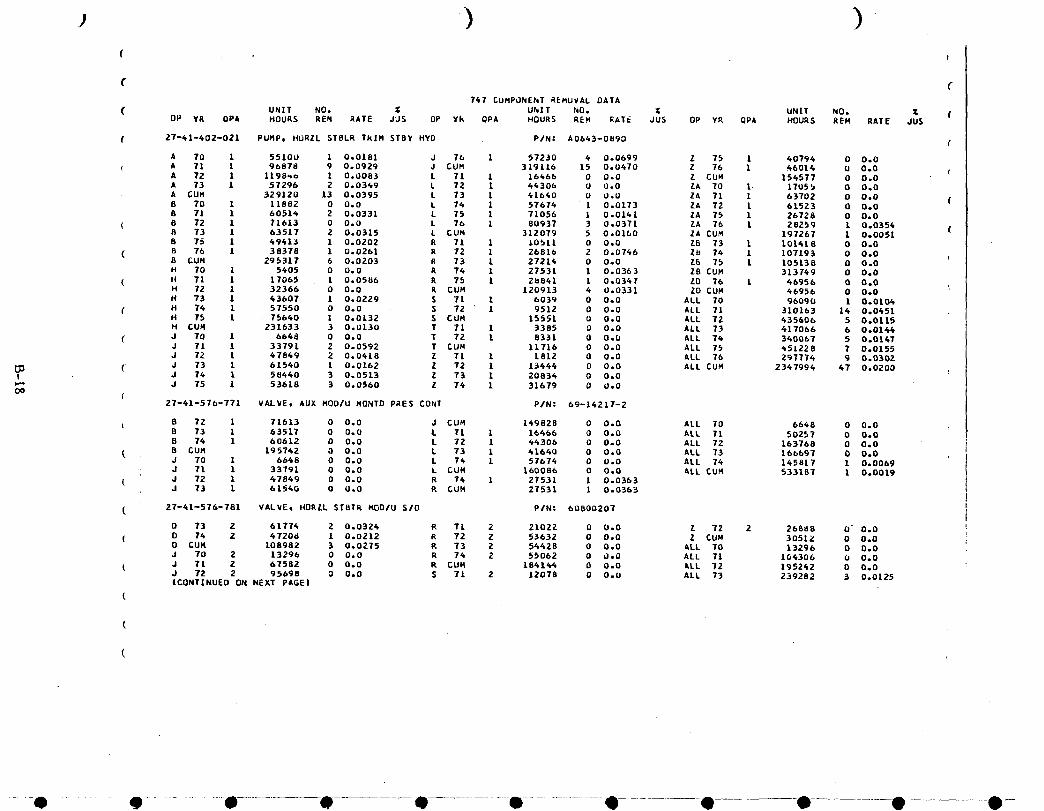
) ){ t
C C747 CUMP_NENT REHUVAL DATA
( UNIT NO. _ UNIT NO. _ UNIT NO. _ (OP YR OPA HOURS REN RATE JUS UP Yk OPA HOURS REM RATE JU5 OP YR QPA HOURS REN RATE JU$
( 27-41-402-021 PUHPo HURZL STBLR TkIN STBY HYD P/N= A0663-0890 (
A 70 1 55100 1 0.0181 J 76 1 57230 4 0.0699 Z 75 1 40796 0 0.0
A 71 1 90878 9 0.0929 J CU_ 319116 15 0°0670 Z 76 1 66014 0 0.0 (A 72 1 1198_o 1 0.0083 L 71 1 16466 0 0.0 Z CUM 156577 0 0.0A 73 1 57296 2 0.0349 L 72 1 66306 0 0.0 ZA 70 1. I7055 0 0.0A GUN 329120 13 0.0395 L 73 1 41640 0 0.0 ZA 71 1 63702 0 0.08 70 1 11882 0 0.0 L 76 1 57676 1 0.0173 ZA 72 L 61523 0 0.0 (8 71 1 60516 Z 0.0331 L 75 1 71056 1 0.0161 ZA 75 1 26728 0 0.0
( B 72 I 71613 0 0.0 L 76 1 80937 3 0.0371 ZA 76 1 28259 1 0.035_ (R 73 1 63517 2 0.0315 L CUH 31Z079 5 0.0160 ZA CU_ 197267 1 0.00518 75 1 69413 1 0.0202 R 71 1 10511 0 0.0 Z8 73 1 101618 0 0.0
( B 76 1 38378 1 0.0261 R 72 1 26816 2 0.0766 Zb 76 1 107193 0 0.08 CUH 295317 6 0.0203 R 73 L 27216 0 0.0 26 75 1 105138 0 0.0H 70 1 5405 0 0.0 R 74 1 27531 1 0.0363 ZB CUH 313769 0 0.0
( H 71 1 17065 1 0.0586 R 75 1 2U841 1 0.0347 ZD 76 1 46956 0 0.0H 72 1 32366 0 0.0 R CUM 120913 4 0.0331 ZD CUH 66956 0 0.0H 73 1 63607 1 0.0229 S 71 1 6039 0 0,0 ALL 70 96090 1 0.0106
( H 76 1 57550 0 0.0 S 72 1 9512 0 0-0 ALL 71 310163 16 0.0651H 75 1 75660 1 0.0132 S CUH 15551 0 0.0 ALL TZ 635606 5 0.0115H CUH 231633 3 0.0130 T 71 1 3385 0 0.0 ALL 73 617066 6 0.0166
( J 70 1 6668 0 0.0 T 72 1 8331 0 0.0 ALL 74 360067 5 0.016TJ 71 1 33791 2 0=0592 T CUM 11716 0 0.0 ALL 7_ 651228 7 0.0155J 72 1 47849 2 0.0418 Z 71 1 L8[Z 0 0o0 ALL 76 297774 9 0.0302
03 ( J 73 1 61560 1 0.0162 Z 72 1 13664 0 0.0 ALL CUH 2367994 67 0.0200I J 76 I 58460 3 0o0513 Z 73 1 20836 0 0.0_" J 75 1 53618 3 0.0560 Z 74 1 31679 0 U.OO0
27-61-576-771 VALVE, AUX NOD/U NONTD PRES CONT PiN: 69-16217-2
t B 72 1 71613 0 0.0 J CUH 149828 0 0.0 ALL 70 6668 0 0.0B 73 1 63517 0 0.0 L T1 1 16666 0 0.0 ALL T1 50257 0 0.08 74 1 60612 0 0.0 L 72 1 66300 0 0.0 ALL 72 163768 0 0.0
( 8 CUH 195762 0 0.0 L 73 1 61640 0 0.0 ALL 73 166697 0 0.0J 70 1 66_8 0 0.0 L T_ 1 5767_ 0 0.0 ALL 74 165817 1 0.0069
• J Tl 1 33791 0 0.0 L CUN 160086 0 0.0 ALL CUH 533187 1 0.0019( J 72 1 _7869 0 0.0 R 74 1 27531 1 0.0363
J 73 1 61560 0 0,0 R CUH 27531 1 0.0353
( 27-61-576-781 VALVE, HORZL STBT_ HOO/U S/O PIN= 60B00207
0 73 2 617T6 2 0.0324 R T1 2 21022 0 0.0 Z 72 2 26888 0" 0.0( D 76 2 47208 1 0.0212 R 72 2 53632 0 0.0 Z CUM 30512 0 0.0
O CUN 108982 3 0.0275 R 73 2 5_628 0 0.0 ALL TO 13296 0 0.0J To 2 13296 0 0.0 R 76 2 55062 0 0.0 ALL 71 104306 U 0.0
( d 71 2 6T582 0 0.0 R CUH 1841_4 0 0.0 ALL 72 195242 0 0o0J 72 2 95098 0 0.0 S 71 2 12078 0 0.0 ALL 73 239282 3 0.0125ICONTINUED ON NEXT PAGEI
(
O 0 ....... O............... O O • ....................O.............. -O O O 0-
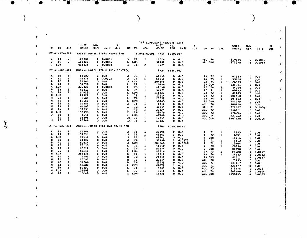
• - ............• .....................• .................-O....................ok.......... • ..................• ............ m ........ 6 ............ • ....
) ) )( f,
747 COMP3NENT REMOVAL DATA
UNIT NO. _ UNIT NO. Z UNIT NO. . T (( OP YR QPA HOURS REq _ATE JJS OP YR OPA HOURS REM RATE JUS OP Y_ QPA HOURS REH RATE JUS
27-61-576-781 VALVE, HORZL STBTR HOD/U $/0 |CUNTINUEUI P/N: 60_00207 (
J 73 2 123080 L 0.0081 S 72 2 19024 0 0.0 ALL 7¢ 219150 2 0.009|J 74 2 116880 1 0.0086 S CUM 31102 0 0.0 ALL CUM 771276 5 0.0065J CUH 410536 2 0.0048 Z 11 2 3624 0 0.0 {
27-41-681-011 ORi/Mt HORZL $TELR TRIM CONTROL P/N= 65680562 (
A 70 1 55100 0 0.0 J 73 1 61540 0 0°0 ZA 72 1 61523 0 0°0
( A 71 1 9687_ 1 0.0103 J 76 1 58440 0 O.U ZA 73 1 59928 0 0.0 (A 72 1 119846 0 0.0 J CUH 208268 0 0.0 ZA 74 1 26583 0 0.0A 73 1 57296 0 0.0 L 71 1 16466 0 0.0 ZA CUH 228791 0 0.0
( A CUH 329120 1 0.0030 L 73 1 41640 0 0.0 Z8 70 1 26018 0 0°0B 73 1 63517 0 0.0 L 74 1 57674 0 0.0 Z5 71 1 68943 0 0.0 (B 74 1 60612 0 0.0 L CUH 115780 0 0.0 Z8 72 1 81183 0 0.08 CUH 124129 0 0.0 R 73 1 27216 0 0.0 Z8 73 1 10161_ 0 0o0H 70 1 5405 0 0.0 R 74 1 27531 0 0.0 Z_ 74 1 107193 0 0.0H TX 1 17065 0 O.0 R CUH 56745 0 0°0 ZB CUH 362755 O 0.0
( H 72 1 32366 0 0.0 Z 71 1 1812 0 0.0 ALL 70 105226 0 0.0H 73 1 43607 0 0.0 Z 72 1 13444 0 0°0 ALL 71 278657 1 0.003_H 7_ 1 57550 D 0.0 Z 73 1 20834 0 0o0 ALL 72 356211 0 0.0
, H CUH 155993 0 0.0 Z 76 1 31679 0 0°0 ALL 73 476994 0 0.0J 70 1 6648 0 0.0 Z CUM 67769 0 0.0 ALL 74 627262 0 0.0J 71 1 33791 0 0.0 ZA 70 1 17055 0 0.0 ALL CU_ 1047350 1 0.0006
( J 72 1 47849 0 0.0 ZA 71 1 63702 0 0°0I
w-. 27-61-687-081 MOO/b. HOST8 STBV HYD POWER S/O P/N: 60600241-1
A 72 1 119846 0 0.0 J Tl 1 33791 0 0°0 T 71 1 3385 0 0.0A 73 1 57296 0 0.0 J 72 1 67849 0 0.0 T 72 1 8331 0 0.0A CUH 177162 0 0.0 J 73 1 61560 0 0.0 T CUM 11716 0 0.0B 70 1 11882 0 0.0 J 76 1 58440 1 0.0171 Z 71 1 1812 0 0.0B 71 1 60514 0 0.0 J CUH 208268 1 0.0068 Z 72 1 13446 0 0.08 72 1 71613 0 0.0 L 73 1 41640 0 0.0 Z 73 1 20836 0 0.08 73 1 63517 0 0.0 L 76 1 57674 0 0o0 Z CUH 36090 0 0°08 74 1 60612 0 0.0 L CUH 99316 0 0.0 ZA 73 1 59928 1 0.0167
( 8 CUM 268138 0 0.0 R 71 1 10511 0 0.0 ZA 74 1 26583 2 0.0752H 70 1 5405 0 0.0 R 72 1 26816 0 0o0 ZA CU_ 86511 3 0°0347H 7| 1 17065 0 0.0 R 73 1 27214 0 0.0 ALL T0 23935 O O.0
( H 72 1 32366 0 0.0 R 76 1 27531 0 UoO ALL 71 133117 0 0.0H 73 1 63607 0 0.0 R CUM _2072 0 0o0 ALL 72 329777 0 0.0H ?6 1 57550 0 0.0 S 71 1 6039 0 0o0 ALL 73 375576 1 0.0027
( H CUH 155_93 0 0.0 S 72 1 9512 0 0.0 ALL 76 288390 3 0.010_d 70 1 6668 0 0.0 S CUH 15551 0 0.0 ALL CUN 1150795 6 0.0035
(
(

( !
€ (741COHPONENT REHOVAL OATA
UhlT NO. Z UNIT NO. Z UNIT NO. Z C"( OP YR OPA HOURS . REH RATE JU$ OP Yk OPA HOURS RIM RATE JUS UP YK QPA HOURS REM .kATE JUS
f 27-41-687-101 HOD IU. H_RZL STBLR TRIM CONT P/NZ 60880027-1 I
A 70 2 110200 3 0.0272 J 75 Z 107236 1 0.u093 ZA 70 2 3411U 0 0.0A 71 2 193766 20 0.1032 J 76 2 1144b0 2 0.0175 ZA 71 2 127406 3 0.0235A 72 2 2J9697 7 0.0292 J CUM 638232 9 0.0141 ZA 72 2 12304& 2 0.0163A 73 2 114592 0 0.0 L 71 2 32932 0 0.0 ZA 73 2 119856 6 0.050lA CU_ 6582q0 30 0.0456 L 73 2 83280 0 0.0 ZA 74 2 53166 8 0.1505 (8 70 2 23764 0 0.0 L 74 2 115348 2 0.0173 ZA 75 2 53456 O- 0.0B 71 2 121028 0 0.0 L 75 2 142112 11 0.0774 ZA T6 2 5651B 3 0.0531
( B 72 2 143226 0 0.0 L 76 2 161874 17 0.1050 ZA CUH 567556 22 0.0388 (U T3 2 127034 1 0.0079 L CUM 536546 30 0.0560 ZB 70 2 48036, 3 0.0625B 74 2 121224 2 0.0165 R 71 2 21022 O 0.0 ZB 71 2 97886 8 0.0817
B 75 2 98826 6 0.0607 R 72 Z 53632 3 0.0559 ZB 72 2 162366 12 0.0739U 76 2 76756 1 0.0130 R 73 2 54428 1 0.0184 78 73 2 202836 6 0.0296B CUH 711858 10 0.0140 R 74 2 55062 0 0.0 ZB 74 2 214386 S 0.0233H Tu 2 10810 1 0.0925 100 R 75 2 57682 0 O.O ZB 75 2 210276 6 0.0285
( H 71 2 34130 2 0.0586 R CUH 241826 4 0.0165 ZB 76 2 213894 8 0.037&H 72 2 64232 1 0.0154 S 71 2 12078 0 0.0 ZE CU½ 1149680 48 0.0416
( H 73 2 87214 0 0.0 S CUH 12078 0 0.0 ZD 76 2 93912 0 0.0H 74 2 115100 0 0.0 T 71 2 6770 I 0.1477 ZD CUH 93912 0 0.0H 75 2 151280 1 0.0066 T CUH 6770 1 0.1477 ALL 70 2_0216 8 0.0333
H 76 2 161498 0 0.0 Z 71 2 3624 0 0.0 ALL 71 718212 35 0.0487H CUH 624764 5 0.0080 Z 72 Z 26888 0 0.0 ALL 72 909280 27 0.0297J 70 2 13296 1 U.0752 Z 73 2 41668 0 0.0 ALL 73 953988 15 0.0157
[]_ J 71 2 67582 1 0.0148 Z 74 2 63358 0 0.0 ALL 74 854524 18 0.0211I I
t,,.) J 72 2 95698 2 0.0209 Z 75 :_ 81588 0 0.0 ALL 75 902456 25 0o0277O J 73 2 123080 1 0.0081 Z 76 92028 0 0.0 ALL 76 970940 31 0.0319
( J 7_ 2 116880 1 0.0086 Z CUM 30915_. 0 0.0 ALL CUN 5549616 159 0.0287 100 (
27-60-'604-181 OUADRANTt SPLR/SPBRK HANDL BRAKE PIN: 50196/(
A 71 L 96878 0 0.0 J 70 1 6648 0 0o0 ZA 71 1 63702 0 0.0A 72 1 119846 1 0.0083 J 71 1 33791 0 0o0 ZA 72 1 61_23 0 0.0
( A 73 1 57296 0 0.0 J 72 1 _7849 0 0.0 ZA 73 1 59928 0 0o0A CUM 27_020 1 0.0036 J 73 1 61540 0 0o0 ZA 74 1 26583 D 0o00 70 1 11882 0 0.0 J 74 1 50440 0 0o0 ZA CUM 228791 D OoO
(CONTINUED ON NEXT PAGE(
l
.... 0 ........... q ......... 0............... O......................0............ O-...................O ...........--U O- 0 .............. O-

• • Q • • o • • • • •
\(
(767 COMPONENT REMOVAL DATA
( UNIT NO. Z UNIT NO. Z UNIT NO.OP YR OPA HOUR_ REM RATE JUS OP YR OPA HOURS REN RATE JUS DP YR QP& HOURS REM RATE JUS
( 27-60-404-18| QUAGRANT, SPLR/SPBRK HANDL 8_AXE ICONTINUED) P/N: 50196
8 11 1 60_14 0 0.0 J EUM 208268 0 0.0 Z8 73 1 101418 0 0°08 72 1 71613 0 0.0 L 71 l 16466 0 O.Q 28 76 1 107193 U 0°0B 73 1 63517 0 0°0 L 73 [ 41660 0 0.0 Z8 CUM 208611 0 0.08 76 1 60612 0 0°0 L 74 1 57674 4 Uo0694 ALL 70 40990 0 D.O
( 8 CUM 268138 0 0°0 L CUM 115780 4 0°0345 ALL 71 290228 0 0°0 (H 70 1 5405 0 0.0 Z 71 1 1812 0 0.0 ALL 72 366661 1 0.0029H 71 1 17065 0 0o0 Z 72 1 13446 0 0.0 ALL 73 469780 0 0.0
( H 72 1 32_66 0 0.0 Z 73 1 20834 0 0.0 ALL 74 399731 4 0.0100 (H 73 1 43607 0 0°0 Z 76 1 31679 0 0.0 ALL CUR 1527370 5 0.0033H 74 E 57550 0 0.0 Z £UM 67769 0 0.0
( H CUM 155993 0 0.0 ZA 70 1 17055 0 0.0 ("
2T-b0-659-'-021 DIFFERENTIAL, FC 5PLR/SPBRK P/N: 65880836
(A 70 2 110200 0 0.0 L 73 2 83280 0 0.0 Z CUH 135538 0 0.0A 71 2 193756 0 0°0 L 76 2 115348 0 0.0 ZA 70 2 36110 0 0.0
( A 72 2 239692 0 0.0 L CUM 231560 0 0.0 ZA 71 2 127404 0 0.0A 73 2 114592 0 0°0 R 71 2 21022 0 0°0 ZA 72 2 123046 0 0.0A CUM 658240 0 0.0 R 72 2 53632 0 0.0 ZA 73 2 119856 0 0.0
L 8 70 2 23766 0 0o0 R 73 2 54428 0 0°0 ZA 74 2 53166 0 0.08 71 2 121028 0 0.0 R 74 2 55062 0 0.0 ZA CUM 457582 0 0.08 72 2 1_3226 O 0.0 R CUR 18414_ 0 0.0 28 73 2 202836 0 0°0
I1_ B 73 2 127034 0 0.0 S 71 2 12078 0 0.0 Z8 74 2 214386 0 0°0(b,,) B 74 2 121224 0 0.0 S 72 2 19024 0 0.0 28 CUM 417222 0 0.0
B CUM 536276 0 0.0 S CUM 31102 0 0°0 ALL 70 181370 0 0°0
( J 70 2 13296 0 0.0 T 71 2 6770 0 0.0 ALL 71 586196 0 0°0J 71 2 67582 0 0.0 T 72 2 16662 0 0.0 ALL 72 717868 0 0.0 "J 72 2 95698 0 0.0 T CUM 23432 0 0°0 ALL 73 866774 . 0 0.0
J 73 2 123080 0 0.0 Z 71 Z 3624 0 0.0 ALL 74 739626 0 0o0 :J 76 2 116880 0 0.0 Z 72 2 26888 0 0°0 ALLCUM 3091632 0 0°0J CUR 416536 0 0.0 Z 73 2 41668 0 0.0
L 71 2 32932 0 0.0 Z 74 2 63358 0 0.0 (
27-60-697-011 SEQ/M, FLIGHT CONT $PGILER/SPBRK PIN: 65680859
CA T0 1 55100 0 0.0 J 73 1 61540 O 0°0 Z 73 1 20834 0 O°0A 71 1 96878 O 0.0 J 74 1 584_0 0 0°0 Z 74 1 31679 0 0°0
( A 72 1 119846 0 0.0 J CUM 208268 1 0.0048 Z CUN 67769 0 0.0A 73 1 57296 U 0.0 L 71 1 16466 0 0°0 ZA TO 1 17055 0 0.0A CUH 329120 0 0.0 L 73 1 41660 1 0.0260 ZA 71 1 63702 0 0*0
( B 70 1 11882 0 0°0 L 74 1 57674 0 0°0 ZA 72 1 61523 O 0.0B 71 1 60516 0 0.0 L _UM 115T80 1 0.0086 ZA 73 1 59928 0 0.0B 72 1 71613 0 0.0 R 71 1 10511 0 0°0 ZA 74 1 26583 0 0.0
( 8 73 1 63517 0 0°0 R 72 1 26816 0 0.0 ZA CUM 228791 0 0.05 74 1 b061Z U 0.0 R 73 1 27214 0 0.0 Z8 73 1 101418 0 0.0ICONTINUED ON NEXT PAGE)
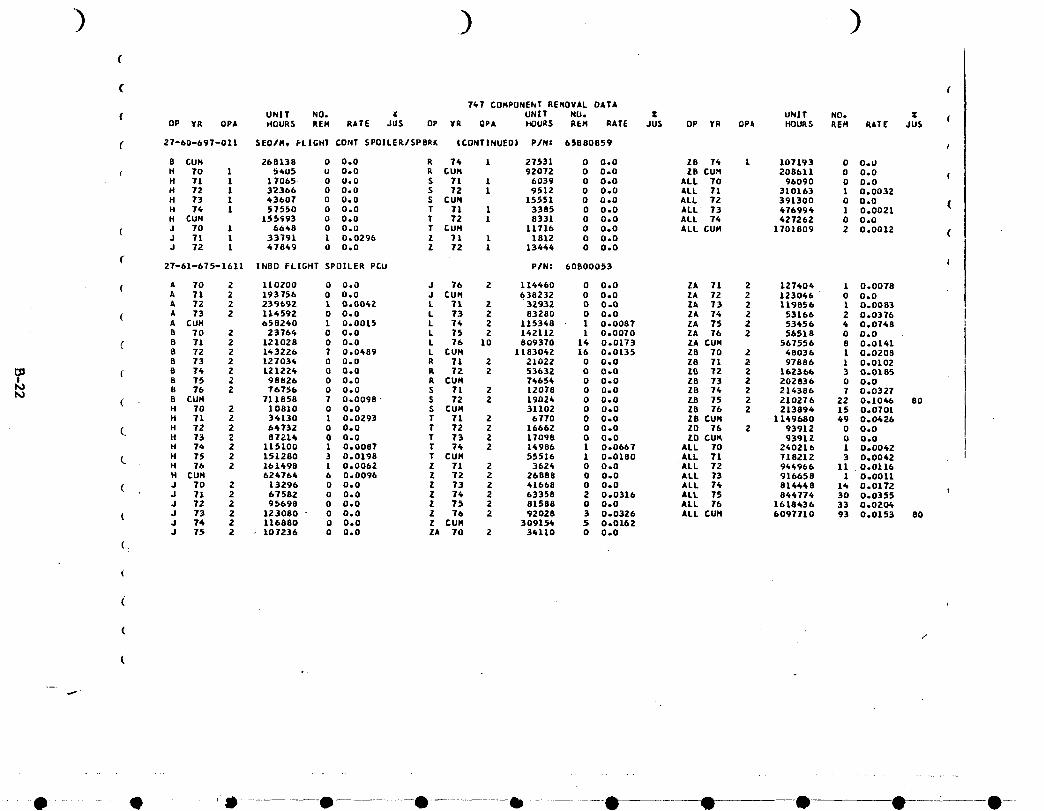
) ) )
( (
747 COMPUNEhT RENOVAL DATA
f UNIT NO. _ UNIT NU. Z UNIT NO. Z (OP YR OPA HOURS REH RATE JUS DP YR QPA HOURS REH RATE JUS OP YR QPA HOURS REH RATE JUS
( 27-60-697-011 SEO/Mt FLIGHT CONT SPO|LER/SPBRK |CDNT|NUED) P/Nz 65B80859 €
B CUN 268138 0 0.0 R 74 1 27531 0 0.0 ZB 74 1 107193 0 O.U
r H 70 1 5405 o 0o0 k CUH 92072 0 0.0 ZB CUH 208611 0 0.0 (H 71 1 17065. 0 0.0 S 71 1 6039 0 0.0 ALL 70 96090 0 0.0H 72 1 32366 0 0.0 S 72 1 9512 0 0.0 ALL 71 310163 1 0.0032
H 73 1 43607 0 0.0 S £UN 15551 0 0.0 ALL 72 391300 0 0,0 (H 74 1 57550 0 0.0 T 71 1 3385 0 0.0 ALL' 73 476994 1 0.0021H CUH 155993 0 0.0 T 72 1 8331 0 0.0 ALL 74 627262 0 0.0
( J 70 1 66_8 0 0.0 T _UH 11716 0 0.0 ALL CUH 1701809 2 0.0012 (J 71 1 33791 1 0.0296 Z 71 1 1812 0 0.0J 72 1 47849 0 0.0 Z 72 1 13464 0 0.0
C27-61-675-1611 INBD FLIGHT SPOILER PCU P/N= 60800053
( A 70 2 110200 0 0.0 J 76 2 114460 0 0.0 ZA 71 2 127404 1 0.0078A 71 2 193756 0 0.0 J £UM 638232 0 0.0. ZA 72 2 12304.8 0 0.0A 72 2 239692 1 0.0062 L 71 2 32932 0 0.0 ZA 73 2 119856 1 0.0083
( A 73 2 114592 0 0.0 L 73 2 83280 0 0.0 ZA 76 2 53166 2 0.0376A CUN 658240 1 0.0015 L 74 2 115368 1 0.0087 ZA 75 2 53456 4 0.0748B 70 2 23764 0 0.0 L 75 2 142112 1 0.0070 ZA 76 2 56518 0 0.0
8 71 2 12102B 0 0.0 L 76 10 809370 16 0.0173 ZA CUM 567556 8 0.01418 72 2 1_3226 7 0.0489 L CUM 1183062 16 0.0135 Z8 70 2 48036 1 0.02088 73 2 127034 0 0.0 R 71 2 21022 0 0.0 Z8 71 2 97886 1 0.0102
( B 74 2 121224 0 0.0 R 72 2 53632 0 0.0 ZB 72 2 16236b 3 0.0185I B 75 2 98826 0 0.0 R CUH 74654 0 0.0 Z8 73 2 202836 0 0o0
I%) B 76 2 76756 0 0.0 S 71 2 12078 0 0o0 ZB 74 2 214386 7 0.0327I'0( 8 CUH 711858 7 0.0098 S 72 2 19026 0 0.0 ZB 75 2 210276 22 0.1046 80
H 70 2 10810 0 0.0 S CUH 31102 0 0.0 ZB 76 2 213894 15 0.0701H 71 2 34130 1 0.0293 T 71 Z 6770 0 0.0 ZB CUH 1169/)80 4g 0.0426
H 72 2 64732 0 0.0 T 72 2 16662 0 0.0 ZD 76 2 93912 0 0.0H 73 2 87214 0 0.0 T 73 2 17098 0 0o0 10 CU_ 93912 0 0.0H 74 2 115100 1 0.0087 T 74 2 14986 1 0.0667 ALL 70 240218 1 0.0042
H 75 2 151280 3 0.0198 T CUN 55516 1 0.0180 ALL 71 718212 3 0.0042H 76 2 161498 1 0.0062 Z 71 2 3626 0 0.0 ALL 72 944966 11 0.0116H CUH 624764 6 0.0096 Z 72 2 26888 0 0,0 ALL 73 916658 1 0.0011
( J 70 2 13296 0 0.0 Z 73 2 41668 0 0.0 ALL 74 814448 1_ 0.0172J 71 2 67582 0 0.0 Z 74 2 63358 2 0.0316 ALL 75 844774 30 0.0355J 72 2 95698 0 0.0 Z 75 2 81588 0 0.0 ALL 76 1618436 33 0.0204.
( J 73 2 123080 " 0 0.0 Z 76 2 92028 3 0.0326 ALL CUH 6097710 93 0.0153 80J 74 2 116880 0 0.0 Z CUH 30915_ 5 0.0162J 7_ 2 • 107236 0 0.0 ZA 70 2 34110 0 0.0
(_
(
(
( /,
°.
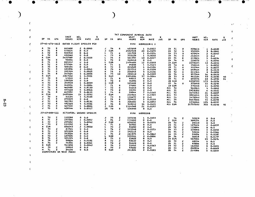
• .... O ......... e .........................i ........................U .................0 ........... • ...............O..................e- ....................® ..................• ....
( (747 COMPONENT REMOVAL DATA
UNIT NO. _ UNIT NO. Z UNIT NO. Z (f OP YR QPA HOURS REH RATE JUS OP YR QPA HOURS REN RATE JUS OP YR OPk HOURS _EH RATE JUS
C 27-b|-b7_-|612 DUTBO FLIGHT SPOILER PCU PIN: 60B80008-| I €
A 70 8 640_00 2 0.0045 J 76 8 457840 1 0.0022 2A 71 8 509616 1 0.0020
( A 71 8 775026 0 0.0 J CUH 2552928 20 0.0078 ZA 72 b 492186 3 0.0061 tA 72 8 958768 0 0.0 L 71 U 131728 1 0.0076 ZA 73 8 679624 2 0.0062A 73 8 458368 0 0.0 L 73 8 333120 1 0.0030 ZA 74 8 212664 0 0.0
A CU_ 2632960 2 0.0008 L 74 8 661392 10 0.0217 ZA 75 8 213824 5 0.023_ (8 70 8 95056 0 0.0 L 75 B 568648 0 0.0 ZA 76 8 226072 1 0.0044B 71 8 484112 0 0.0 L CUH 1494688 12 0.0080 ZA CU_ 2270224 12 0.0053
€ B 72 8 57290_ 0 0.0 R 71 b 84088 1 0.0119 28 To 8 192144 1 0.0052 (8 73 8 _08136 0 0.0 R 72 8 21_528 6 0.0186 Z8 71 B 391544 3 0.00778 74 8 684896 2 0.0041 R 73 8 217712 3 O.Ol3B Z8 72 B 649464 B 0.0123
( 8 75 8 395306 1 0.0025 R 76 B 220248 3 0.0136 Z8 73 8 811.344 8 0.00998 76 8 307024 3 0.0098 R 75 10 288410 6 0.0208 ZE 74 8 857544 36 0.0620B CUM 2847632 6 0.0021 R CUH 1024986 17 0.0166 ZB 75 8 841104 49 0.0583 90
( H 70 8 63260 0 0.0 S 71 8 68312 0 0.0 28 76 8 855576 68 0.0795 94H 71 8 136520 0 0.0 S 72 8 76096 0 0.0 20 CUH 6598720 173 0.0376H 72 B 258928 1 0.0039 S GUM 124608 0 0.0 ZD 76 8 375668 11 0.0293
€ H 73 8 348856 3 0.0086 T 71 8 27080 0 0.0 Z0 CUH 375648 11 0.0293H 74 8 660400 6 0.0130 T 72 8 66648 0 0.0 ALL 70 960866 _ 0.0042H 75 8 605120 4 0.0066 T 73 8 68392 0 0.0 ALL 71 2858352 6 0.0021
t H 76 8 t_5992 9 0.0139 T 74 8 5994_ 7 0.1168 ALL 72 3672312 21 0.0057H CUH 2699056 23 0.0092 T CUH 222066 7 0.0315 ALL 73 3886344 21 0.0056J 70 8 53184 1 0.0188 Z 73 8 166672 0 0.0 ALL 74 3478060 71 0.0206
( J 71 8 270328 0 0.0 Z 76 8 253432 3 0.0118 ALL 75 3667506 73 0.0199I J 72 8 382792 5 0.0131 Z 75 8 326352 3 0.0092 ALL 76 3236266 10_ 0.0337I_) J 73 8 692320 4 0.0081 Z 76 8 368112 16 0.0435 ALL CUM 21757682 305 0.0140 92_J ( J 7_ 8 667520 6 0.0086 Z CUM 1114568 22 0.0197
J 75 8 62894_ 5 0.0117 ZA 70 8 136660 0 0.0
( 27-62-008-|11 ACTUATOR, GROUND SPOILER P/N: 60880008
A 70 2 110200 0 0.0 J 75 2 107236 1 0.0093 Z 76 2 92028 O 0.0( A 71 2 193756 1 0.0052 J 76 2 11_60 0 0.0 Z CUH 309154 0 D.O
A 72 2 239692 1 0.0062 J CUM 638232 5 0.0078 ZA 70 2 36110 0 0.0A 73 2 114592 0 0.0 L 71 2 32932 0 0.0 ZA 71 2 127404 2 0.0157
( A CU_ 658240 2 0.0030 L 73 2 83280 0 0.0 ZA 72 2 123066 0 0.0B 70 2 23764 0 0.0 L 76 2 115368 2 0.0173 ZA 73 2 119856 3 0.02508 71 2 121028 0 0.0 L 75 2 162112 0 0.0 ZA 74 2 53166 3 0.056_
( 8 72 2 163226 0 0.0 L 76 2 161876 1 0.0062 ZA 75 2 53656 1 0.0187B 73 2 127036 0 0.0 L CUM 535546 3 0.0056 ZA 76 2 56518 1 0.01778 74 2 121226 0 0.0 R 71 2 21022 0 0.0 ZA CUH 567556 10 0.0176
( B 75 2 98826 ! 0.0101 R 72 2 53632 0 0.0 26 70 2 48036 0 0.08 76 2 76756 2 0.0261 R 73 2 56428 0 0.0 ZB 71 2 97886 0 0.0B CUN 711858 3 0.0062 R 76 2 55062 2 0.0363 ZB 72 2 162366 8 0.0493
( H 70 2 10810 0 0.0 R 75 2 57682 0 0.0 28 73 2 202836 1 0.0049H 71 2 34130 0 0.0 R CUN 261826 2 0.0083 Z8 74 2 216386 5 0.0233|CONTINUED UN NEXT PAGE|
t

) ) )(
( (747 CONPONENT kEHOVAL DATA
UNIT NO. Z UNIT NU. Z UNIT NO. Z (f OP YR OPA HOURS REN RATE JdS OP YR UPA HOURS REM RATE JUS OP YR QPA HOURS REN RATE JUS
C 27-/32-008-111 ACTUAIOR. GROUND SPOILER (CONTINUED| P/N: 60580008 (
H 72 2 64732 0 O.U S 71 2 12078 0 0.0 ZB 75 2 210276 6 0.0285
f H 73 2 67214 D 0.0 S 72 2 19026 O 0.0 28 76 2 213B96 8 0.0374 (H 7_ 2 I15100 0 0,0 S CUR 3LlOZ 0 0.0 Z_ CUH 1149680 28 0.024_H 75 2 151280 0 O.O T 71 2 6770 O 0.0 ALL 7U 260216 0 0.0
H 76 2 161698 0 0.0 T 72 2 16662 0 0.0 ALL 71 718212 3 0.0042 (H CUN 6Z4766 O 0.0 T CUH 23632 0 0.0 ALL 72 946966 9 0.0095J 70 2 13296 0 0.0 Z 71 2 3626 0 0.0 ALL 73 953988 6 0.0063
J 71 2 67582 O 0.0 Z 72 2 26888 0 0.0 ALL 74 856524 14 0.0164 fJ 72 2 95698 0 0.0 Z 73 2 61668 0 0o0 ALL 75 902656 9 0.0100J 73 2 123080 2 0.0162 • 74 2 63358 O O.O ALL 76 877028 12 0.0137
( J 74 2 116880 2 0.0171 Z 75 2 81586 O 0.0 ALL CUH 5491390 53 0.0097 C
27-62-008-381 LINEAR ACTUATOR. AUTO SPEED BRAKE P/N: 60860052
( B 70 1 11882 1 0.0842 L 71 1 16666 2 0.1215 • CUM 139321 0 O.O (. B 71 1 60514 7 0.1157 L 73 1 41640 1 0.0240 ZA 70 1 17055 0 0.0
( B 72 1 71613 8 0.1117 L 76 1 57674 6 0.0694 ZA 71 1 63702 4 0.0628B 73 1 63517 2 0.0315 L 75 1 71056 2 0.0281 ZA 72 1 61523 2 0.0325B 74 1 60612 12 0.1960 L 76 1 80937 6 0.0742 ZA 73 1 59928 6 0.1001
( B 75 1 49413 1 0.0202 L CUN 267773 15 0.0560 ZA 74 1 26583 0 0.0B 76 1 38378 3 0.0782 R 71 1 10511 1 0.0951 ZA 75 1 26728 3 0.1122B £UH 355g29 36 0.0955 R 72 1 26816 1 0.0373 ZA 76 1 28259 3 0.1062
t_3 ( H 70 1 5405 0 O.O R 73 1 27216 0 0.0 ZA CUH 283778 18 0.0634H 71 1 17065 0 0.0 R 7_ 1 27531 0 0.0 Z8 73 1 101418 0 0.0I,,J H 72 1 32366 2 0.0618 R 75 1 26661 0 O.O ZB 74 1 107193 0 O.O-i=" C H 73 1 43607 1 0.0229 R CUH 120913 2 0.0165 Z8 75 1 105138 2 0.0190
H T_ 1 57550 7 0.1216 S 71 1 6039 O 0.0 76 76 1 106947 0 0.0H 75 1 75640 1 0.0132 S 72 1 9512 0 0.0 ZB CUH 420696 2 O.O0_BH 76 1 80749 4 0.0495 S CUH 15551 O 0.0 •U 76 1 46956 O 0.0H £UN 312382 15 0.0480 T 71 1 3383 1 0.2954 20 CU_ 66956 0 0.0J 70 1 6648 0 O.O T 72 1 8331 0 0.0 ALL 70 40990 1 0.0264
( J 71 1 33791 3 0.0888 T 73 1 8549 0 0.0 ALL 71 211473 18 0.0851J 72 1 47849 2 0.0418 T 74 1 7493 1 0.1335 ALL 72 258010 15 0.0581J 73 E 61540 3 0.0487 T CUH 27758 2 0.0721 ALL 73 428247 13 0.030_
( J 74 1 58440 0 0.0 Z 73 1 20634 0 O.O ALL 76 434755 24 0.0552J 75 1 53618 2 0.0373 Z 74 1 31679 0 0.0 ALL 75 451228 11 0.OZBXeJ 76 1 57230 7 0.1223 15 Z 75 1 40794 0 0.0 ALL 76 485670 23 0.0476
( J CUN 319116 17 0.0533 Z 76 1 46014 0 0.0 ALL CU_ 2310173 105 0.0655 15
27-62-576--461 CONTROL VALVE, GROUND SPOXLER P/N= 60800235
(A 70 1 55100 0 0.0 J 73 1 61560 O 0.0 Z 73 1 20836 0 0.0A 71 1 96676 0 0.0 J 7_ 1 58_0 0 0.0 Z 74 1 31679 0 0.0
( A 72 1 119846 0 0.0 J CUM 208268 0 0.0 Z CUM 67769 0 0o0A 73 1 57296 0 0.0 L 71 1 16666 0 0.0 26 70 1 17055 0 OeO|£ONTINUED ON NEXT PAGE)
( ,
(" (
C

.....• ......... O ............ • ..............._......o-.......... • ..................-o ..................Q ...................• ...................* .................• ......................e .....
( (
( (7_7 CUHPONENT REHUVAL DATA
U_|T " NO. _ Z UNIT NO. Z UNLT NO. Z C( OP YR OPA HOURS REM RATE JUS OP YR QPA HOURS kEM RATE JUS OP YR QPA HOURS REM RATE JUS
[ 27-62-576o661 CONTROL VALVEt GROUND SPOILER |CO_T|NUED) PIN: 60800235 (
A CUN 3291_0 O ODD L 73 1 61660 0 0.0 ZA 71 1 63702 O 0.0B TO 1 11882 0 ODD L 7¢ 1 57676 0 0.0 ZA 72 1 61523 O 0.0 (
f 8 71 1 6051_ O O.O L £UM 115780 O U.O ZA 73 1 599Z8 2 0.0334B 72 1 71613 U 0.0 R 71 1 10511 0 0.0 ZA 74 1 26583 1 0.03768 73 1 63517 1 0.0157 P 72 1 26816 O UoO ZA CUH 228791 3 0.0131 (
" 8 74 1 60612 O 0.0 _ 73 1 27214 O O.O Z8 73 1 101618 0 O.OB CU_ 268138 1 0.0037 R 74 1 27531 O U.O Z8 74 1 107193 0 0.0
( H 70 1 5405 0 0.0 R CUM '92072 0 O.O ZB CUH 208611 0 0.0 (H 71 1 17065 0 0.0 S 71 1 6039 0 0.0 ALL 70 96090 O 0.0H TZ t 32366 0 0.0 S 72 1 9512 O 0o0 ALL 71 310163 O 0.0
( H 73 1 63607 0 0.0 S CUH 15551 O 0.0 ALL 72 391300 0 0o0H 76 1 57550 O 0.0 T 71 1 3385 0 O.O ALL 73 476996 3 0.0063H CUM 155_93 O 0.0 T 72 1 8331 0 O.O ALL 74 427262 1 0.0023
( J TO 1 6668 O 0.0 T CUR 11716 O 0°0 ALL CUH 1701809 4 0.0024J 71 1 33791 0 0.0 Z 71 1 1812 0 0.0J 72 1 67849 O 0.0 Z 72 1 13466 0 0.0
!t,J
0
iO
APPENDIX CO
POWER CONTROL UNIT WORKSHOP FINDINGS
To derive failure rates for some flight control system modules_ used in the reliability
analysis_ details are required on modes of failure. This appendix includes a history of
!0 components that were sent through the component overhaul shopso_ five airlines. Thehistories are categorized by types o5 descrepanciesfound,
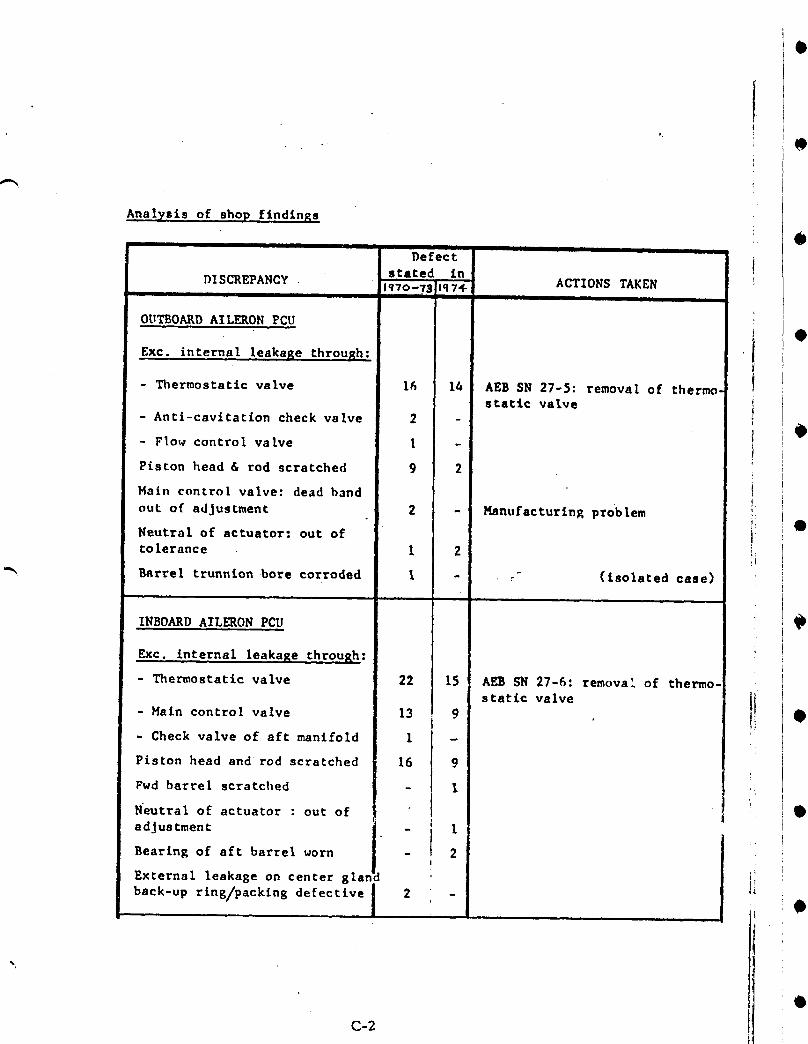
Analysis of shop findings
@I I I I li I II Ill ill II I IIDe£ect J-
DISCREPANCY . stated in, Iq70-75 l{q7_- ACTIONS TAKEN
I I i
OUTBOARD AILERON PCU
Ext. internal leakage through:
- Thermostatic valve 16 14 AEB SN 27-5: removal of thermo.statlc valve
- Anti-cavitatlon check valve 2 -O
- Flow control valve l -f
Piston head & rod scratched 9 2
Main control valve: dead band !
out of adjustment 2 - HanufacturlnR problem !:
Neutral of actuator: out o£ !:tolerance I 2 i_
"_ Barrel trunn£on .bore corroded I - _- (isolated case)
INBOARD AILERON PCU
Exc. internal leakaRe through:
- Thermostatic valve 22 15 AL_ SN 27-6: removal o£ thermo-
static valve I!- Main control valve 13 9 •
- Check valve of aft manifold I -
Piston head and rod scratched 16 9
Fwd barrel scratched - 1[
N'eutral of actuator : out of I •
adjustment - _ L
Bearing of aft barrel worn i _ ,!
glan1External leakage on center "
back-up rlng/packln8 l _ ],i 0|
,@C-2

. ~I\'"
•DISCREPANCY
CENTRAL LATERAL PCP
Excessive int~rn.leaka2e throuRh
DefectStated in"70-73 11174
ACTIONS TAKEN
2
•
•
• ".,-...
•
•
•
..
- Thermostatic valve
- Hain control valve
- Alp actuator
Piston head & rod scratched
Pin in housing of HeV
Seapage through wall of mainhousing
Transducer calibration: out oftolerance
Transfer valve: null bias out oftolerance
Input lever friction test: outof tolerance
AlP override test: out of tol.
AlP detent breakaway: "
AlP velocity & threshold: out oftolerance
INBOARD ELEVATOR PCU
Exc. internal leakage through:
- Thermostatic valve
- Main Control valve
- Compensator check valve
- Time delay valve
Piston head & rod scratched
Pi~ton rod: internal bore corroded
9
1
3
6
1
1
5
2
1
4
I
I
18
21
5
1
8
I
4
1
3
1
"I
4
, 16I
II
AEB SN 27-7: Removal of thermostatic valve
Material defective
Material defective
IHydraulic Research new procedures to improve the adjust~ Iments. ,
I
AEB SN 27-3: removal of thermoRtatic valve
Valve broken, isolated case.
New sealing procedures foraffected rod
i
!I!
•'rransfer valve null bias: out oftolerance 4
C-3
1
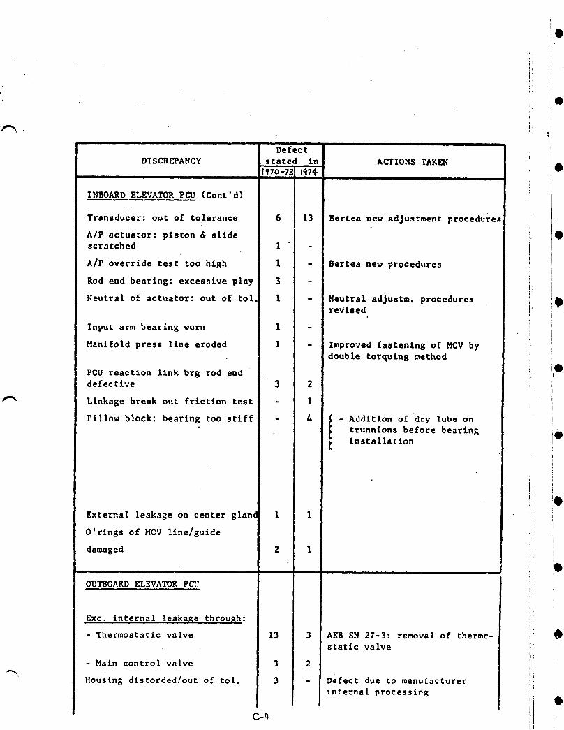
i
?V
; : O
i I i |i
DefectDISCREPANCY stated in ACTIONS TAKEN
1_7o-?s R?. @I I I I I II J I II I
INBOARD ELEVATOR PCU (Cont'd)
Transducer: out of tolerance 6 13 Bertea new adjustment proceduren
A/P actuator: piston & slide
scratched 1 - [I
A/P override test too high I - Bertea new procedures ' !, !
Rod end bearing: excessive play 3 - t 'i
Neutral of actuator: out of tol. I - Neutral adJustm, procedures } !8revised I
' I
Input arm bearing worn I - I
Manifold press llne eroded I - Improved fastening of MCVbydoubte torquing method ',
X
PCU reaction link brg rod end Iidefecclve 3 2
Linkage break out friction test - 1
Pillow block: bearing too stiff - & ,_ - Addition o£ dry lube on'i trunnlons before bearing', I@installationI
.
External leakage on center glanc 1 1 i
O'rings of HCV llne/guide i
damaged 2 I ,Z_
:!
OUTBOARDELEVATORpL_J ":i!i
EXC. internal !eakage .through: ii!.
- Thermostatic valve 13 AEB SN 27-3: removal of thermc- I' •
I "static valve i
- Main control valve 3 !-, ii' Housing dlstorded/out of tol. 3 Defect due to manufacturer li
internal processlng ,;
!i"C-t_
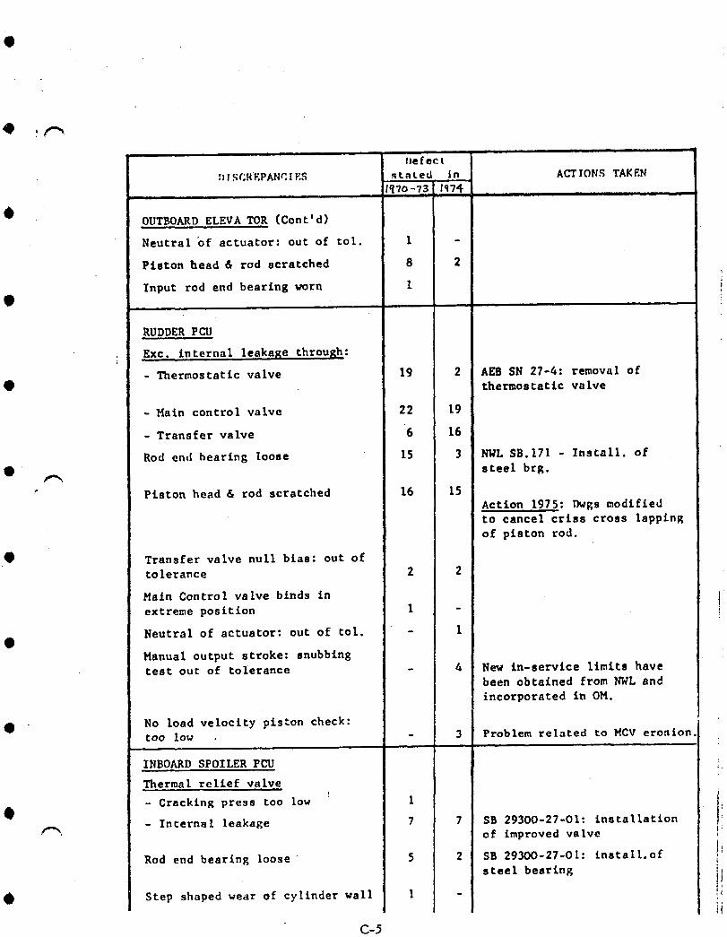
l =,
l_efect
:_ISCREPANr.IES stated in ACTIONS TAKENI_7o-73 lq7_ ..... , , , l
OUTBOARD ELEVATOR (toni'd)
Neutral "of actuator: out of tol. 1 -
Piston bead & rod scratched 8 2
Input rod end bearing worn 1
RUDDER PCU
Ext. internal leakage through:
- Thermostatic valve 19 2 AEB SN 27-4: removal of• thermostatic valve
- Hain control valve 22 19
- Transfer valve 6 16
Rod end bearing loose 15 3 NNL SB.171 - Install. of• ' steel brg.
• Piston head & rod scratched 16 15Action 1975: r_gs modifiedto cancel criss cross lapping
of piston rod.
• Transfer valve null bias: out oftolerance 2 2
Main Control valve binds in
extreme position 1 -
Neutral of actuator: out of tol. - I@
Manual output stroke: snubbingtest out of tolerance - 4 New In-servlce limits have
been obtained from NWL and
incorporated in OH.
O No load velocity piston check:too low - 3 Problem related to MCV erosion,
INBOARD SPOILER PUU
Thermal relief valve
- Cracking press too low
- Internal leakage SB 293OO-27-01: installation_, of improved valve
Rod end bearing loose SB 293OO-27-O1: Install.ofsteel bearing
Step shaped wear of cylinder wall
C-5

DefectDISCREPANCIES stated in ACTIONSTAKEN
.... ,, ,, tqT ,,,Extension check valve O
, - Housing scratched 1
- Ball & cage assy corroded 1
Piston head & rod scratched 1 I!
Hysteresis : out o£ tolerance 1 i: •
Blow dowu check valve eroded 1
Ext. leakage on actuator shaft:seal defective. 2 .'
Pillow blocks bearing worn I •
OUTBOARDSPOILERPCU
Exc. internal leakage through:
- Thermal relief valve 2 SB 29310-27-O1: Installatlon •o£ improved valve.
- Haln control valve 2
- Blow down check valve 8
- Extension check valve 1i
Cracking press coo low on: !_
!
- Blow down check valve I i
- Extension check valve 1 •
Rod end bearing loose 8 SB.29310-27-01: Installation
of steel bearlng.
Piston head & rod scratched 5
Main control valve balance _
check: out of tolerance 3 i_
Hysteresis : out of Col. 6 Input shaft spherical
eccentric worn i:Lock down capability check: iout of tol. 2 i
Hanifold cracked I Attributed to excessive torqtJeof shuttle valve retainer.
I!_ •I
C-6
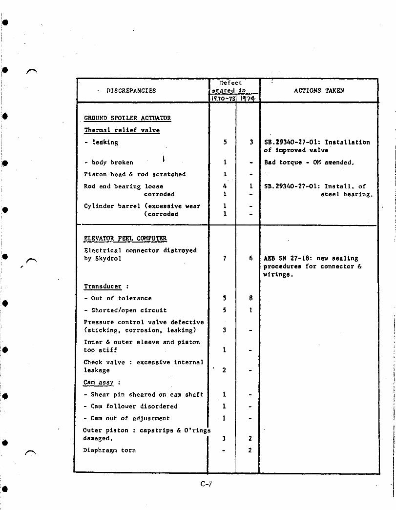
J Defect
i DISCREPANCIES stared in ACTIONS TAKEN
i Iq.70'73 1_7i i i ii i
!0 GROUNDSPOILER ACTUATOR
Thermal relief valve
- leaking 5 3 SB.29340-27-01: Installationof improved valve
iO - body broken _ l - Bad torque - OM amended.i Piston head & rod scratched 1 -
; Rod end bearing loose 4 1 9B.29340-27-O1: Install. ofcorroded 1 - steel bearing.
!O Cylinder barrel (excessive wear 1 -(corroded 1 -
m, i i
i ELEVATORFEEL COMPUTER
Electrical connector distroyed10
/-_ by Skydrol 7 6 AEB SN 27-18: new sealingp procedures for connector &
wirings.
Transducer :
- Out oF tolerance 5 8
- Shorted/open circuit 5 1
Pressure control valve defective
i (sticking, corrosion, leaking) 3 -
i Inner & outer sleeve and pistontoo stiff 1 -
i Check valve : excessive internalI leakage ' 2 -
Cam assy :
- Shear pin sheared on cam shaft I -
- Cam follower disordered 1 -
- Camout of adjustment I -
Outer piston : capstrips & O'rings
i_ damaged. 3 2: _ Diaphragm torn - 2
I
T
!e C-7
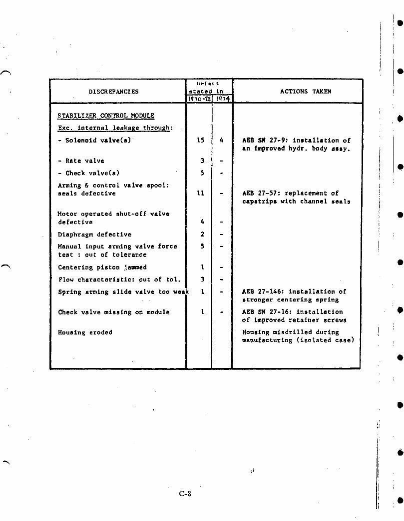
/-_, OfJ_l ett
DISCREPANCIES stated Ln ACTIONS TAKEN
....
STABILIZER CONTROLHODULE i •
Exc. internal leakage through:
- Solenoid valve(s) 15 4 AEB SN 27-92 installation of
an improved hydr. body assy.
- Rate valve 3 -e
- Check valve(s) 5 -
Arming & control valve spool:seals defective 11 - AEB 27-57: replacement of
capstrips with channel seals
Hotor operated shut-off valve •defective 4 -
!Diaphragm defective 2 -
iHanual input arming valve force 5 - ttest : our of tolerance
iCentering piston Jammed 1 -
Flow characteristic: out of tol. 3 -
Spring arming slide valve too veak 1 - AEB 27-146: installation ofstronger centering spring
Check valve missing on module I - AEB SN 27-16: installation •of improved retainer screws
Housing eroded Housing mlsdrilled duringmanufacturing (isolated case)
@
ti •
C-8
i APPENDIX D
• 747 HYDRAULIC SYSTEM FLUID LOSSES
I
• The reliability analysis included the effects of power system failures, Power for; actuator and control modules is available from 8 hydraulic systems and loss of fluid
; through line or component breaks will cause power loss. Included in this appendix is a
i history of 747 hydraulic system fluid losses for 2 airlines from February 1975 to April
! 1976.
ti
i
b
!.
t)
J
e
• D-]

0
•AIRLINEA-747_HYDRAULICSYSTEMLOSSSUMMARYFebruary1975- April 1976
149,069FLIGHTHOURS •
Registration SystemNumber Dat___.ee Lost Description
53 2-3-75 #I #1 EDP L.P. lighton, lost hydraulicfluid,used alternatemode to extendlandinggear. •#1 EDP leak.
70 2-9-75 #1 #1 EDP failedon takeoff,hydraulicquantitydropped,ADP turnedoff. EDP leakingthroughcase drain.
jm40 2-12-75 #4 #4 EDP L.P. lighton, hydraulicquantity
dropped,used alternatemode to extendRH _wing landinggear. #4 EDP shaft shearedand rfiltercollapsed.
70 3-2-75 #4 #4 hydraulicsystemfluid lost, used alternate !•mode to extendT.E. flaps and wing landinggear.Pump pressureline chafedthroughand EDPleakingat drive shaft, i
f50 3-25-75 #4 #4 hydraulicsystemfluid loss, shutoffADP i
and EDP. Hydraulicsystemreturntube leaking. •
54 4-2-75 #1 #I hydraulicsystemquantitydroppedto zero,EDP and ADP off. EDP leakingat partingsurfacecausedby brokenbolt.
51 4-10-75 #I #1 hydraulicsystemquantitylost on finalapproach. Rightbody landinggear downlock •actuatorcracked.
42 4-22-75 .#I #1 hydraulicsystemquantitydroppedto zeroaftergear down and locked. Left body landing
gear downlockactuatorcracked. _•
40 4-28-75 #1 #I EDP L.P. lighton, hydraulicquantitydropped,depressurizedEDP and ADP. Pressureline to pressurefilterleaking.
41 5-4-75 #1 #1 hydraulicsystemquantitydroppedto zeroafter gear extended. Rightbody gear down •lock actuatorcracked.
37 6-6-75 #1 #I hydraulicsystemfluid lost in flightatgear extension. Left body gear down lockactuatorleaking.
D-2 •
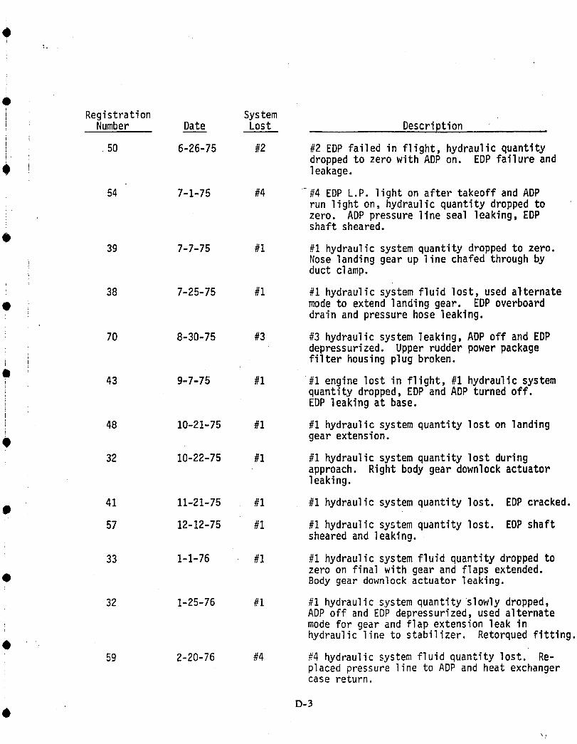
0, Registration System: Number Dat.___e Lost Description
J 50 6-26-75 #2 #2 EDP failedin flight,hydraulicquantityi droppedto zerowith ADP on. EDP failureand0 leakage.
54 7-1-75 #4 -#4 EDP L.P. lighton after takeoffand ADPrun light on, hydraulicquantitydroppedtozero. ADP pressurelineseal leaking,EDPshaft sheared.
039 7-7-75 #1 #1 hydraulicsystemquantitydroppedto zero.
i Nose landinggear up line chafedthroughbyductclamp.
i 38 7-25-75 #1 #1 hydraulicsystemfluid lost, used alternate• mode to extendlandinggear. EDP overboard
drainand pressurehose leaking.
70 8-30-75 #3 #3 hydraulicsystemleaking,ADP off and EDP; depressurized,Upper rudderpower packagei filterhousingplug broken.O
43 9-7-75 #1 #1 enginelost in flight,#1 hydraulicsystemquantitydropped,EDP and ADP turnedoff.
i EDP leakingat base.
i 48 10-21-75 #1 #1 hydraulicsystemquantityloston landing
• gear extension.
32 10-22-75 #1 #1 hydraulicsystemquantitylost duringapproach. Rightbody geardownlockactuatorleaking.
41 11-21-75 #1 #1 hydraulicsystemquantitylost. EDP cracked.e
57 12-12-75 #1 #1 hydraulicsystemquantitylost. EDP shaftshearedand leaking.
33 1-1-76 #1 #1 hydraulicsystemfluid quantitydroppedtozero on finalwith gear and flaps extended.
• Body gear downlockactuatorleaking.
32 1-25-76 #1 #1 hydraulicsystemquantityslowly dropped,ADP off and EDP depressurized,used alternatemode for gear and flapextensionleak inhydraulicline to stabilizer. Retorquedfitting.
59 2-20-76 #4 #4 hydraulicsystemfluidquantitylost. Re-placedpressureline to ADP and heat exchangercase return.
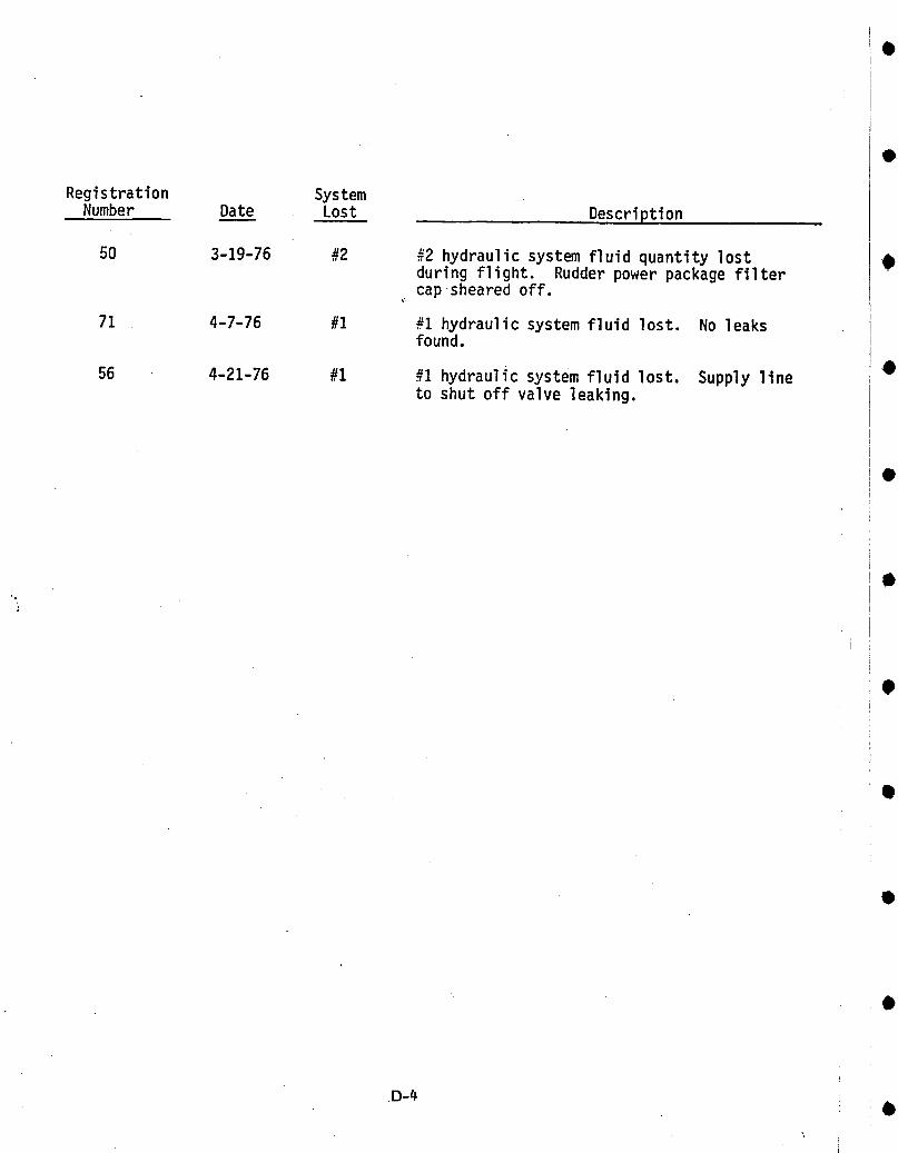
Registration System
Number Date Lost Description
50 3-19-76 #2 #2 hydraulicsystemfluidquantitylost 0duringflight. Rudderpower packagefiltercapsheared off.
71 4-7-76 #1 #1 hydraulicsystemfluid lost. No leaksfound.
e56 4-21-76 #1 #1 hydraulicsystemfluid lost. Supplyline
to shut off valve leaking.
•
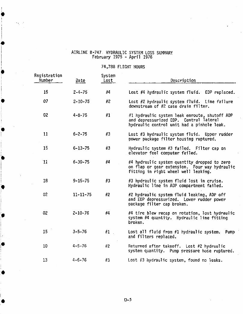
O
AIRLINEB'747 HYDRAULICSYSTEMLOSS SUMMARYi February1975- April 1976ir
74,788FLIGHTHOURS
Registration SystemNumber Dat____ee Lost Description
15 2-4-75 #4 Lost #4 hydraulicsystemfluid. EDP replaced.
@ 07 2-10-75 #2 Lost #2 hydraulicsystemfluid. Line failureL downstreamof #2 case drain filter.
i 02 4-8-75 #1 #1 hydraulicsystemleak enroute,shutoffADPi and depressurizedEDP. Centrallaterali hydrauliccontrolunit had a pinholeleak.
11 6-2-75 #3 Lost#3 hydraulicsystemfluid. Upper rudderpowerpackagefilterhousingruptured,
15 6-13-75 #3 Hydraulicsystem#3 failed. Filtercap onelevatorfeel computerfailed.
11 6-30-75 #4 #4 hydraulicsystemquantitydroppedto zeroon flap or gear extension. Fourway hydraulicfittingin rightwheel well leaking.
18 9-15-75 #3 #3 hydraulicsystemfluid lost in cruise.
Hydraulicline in ADP compartmentfailed.
i 02 11-11-75 #2 #2 hydraulicsystemfluidleaking ADP offIi and EDP depressurized.Lower rudderpower
packagefiltercap broken.iig 02 2-10-76 #4 #4 tire blew recapon rotation,lost hydraulicsystem#4 quantity. Hydraulicline fittingI broken.
R
i 15 3-5-76 #I Lost all fluidfrom #I hydraulicsystem. PumpL and filtersreplaced.
I0 10 4-5-76 #2 Returnedafter takeoff. Lost #2 hydraulicsystemquantity. Pump pressurehose ruptured.
13 4-6-76 #3 Lost #3 hydraulicsystem,foundno leaks.
@ D-5
O
APPENDIX E
!0 SCHEDULED MAINTENANCE REQUIREMENTS
The following pages were extracted from the Boeing 747 maintenance planning
i0 document which includes inspection tasks at recommended frequencies for airplane
! components and systems.i
Scheduled maintenance costs can be assessed from the stated manhours for
Q accomplishing each task.
• E-1
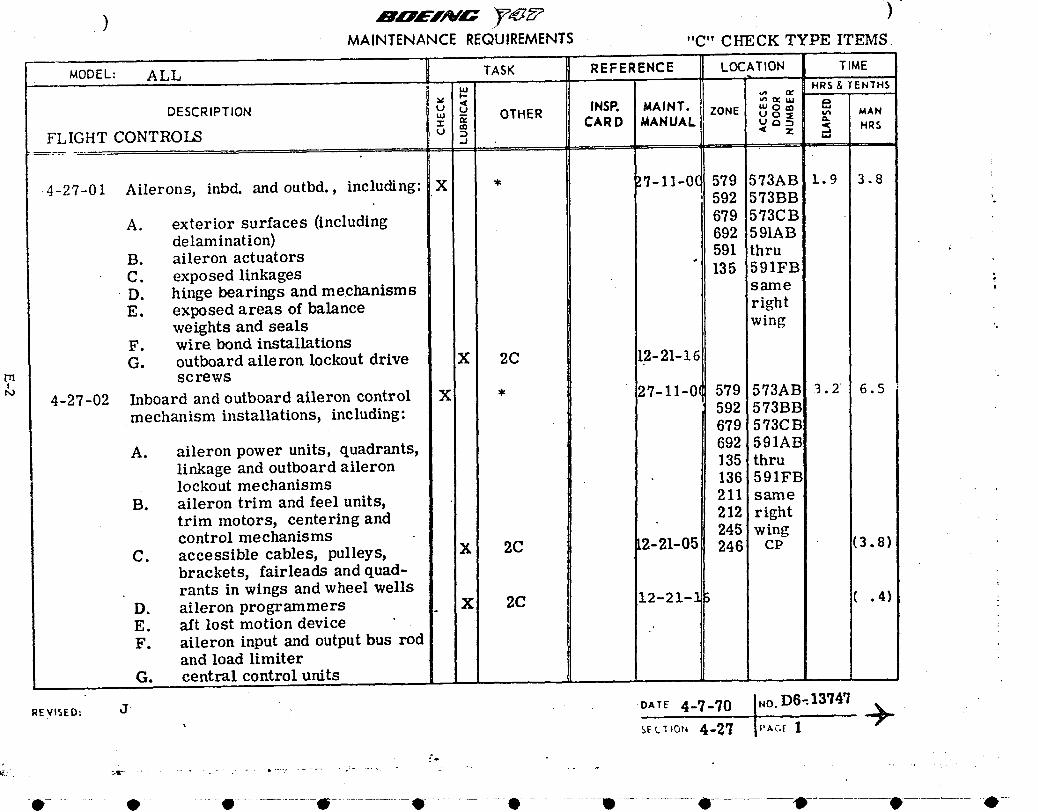
•) 'oEIN= ) .MAINTENANCE REQUIREMENTS "C" CHECK TYPE ITEMS
MODEL: ALL TASK REFERENCE LOCATION. TIMEHRS& TENTHS
DESCRIPTION _J u< INSP. MAINT. "' o ,._ MAN_u - OTHER ZONE u o a:
_ CARD_ANU^L _'_ _ .RsFLIGHT CONTROLS u .
4-27-01 Ailerons, inbd.and outbd, including:X * _.7-11-0(579 573AB 1.9 3.8' 592 573BB
A. exteriorsurfaces (including 679 573CB692 591AB
delamination) 591 thru 'B. aileronactuators
C. exposed linkages 135 591FB :D. hinge bearings and mechanisms same .E. exposed areas of balance 'right
weights and seals 'wingF. wire. bond installationsG. outboard aileron lockout drive X 2C 12-21-16
m screws
4-27-02 Inboardand outboard aileroncontrol X * 27-I]-0(579 573AB 3.2 6.5
592 573BBmechanism installations,including: 679 573CB!
A. aileronpower units,quadrants, 692 591ABilinkageand outboardaileron 135 thru, 136 591FBlockout mechanisms
B. aileron trim and feel units, 211 sametrim motors, centering and 212 rightcontrol mechanisms 245 wing
C. accessiblecables,pulleys, :X 2C 12-21-05 246 CP (3.8)brackets,fairleadsand quad-rants in wings and wheel wells
D. aileron programmers X 2C 12-21-] , ( . 4)E. aft lost motion device ..F. aileron input and output bus rod
and load limiterG. central control units
REVISED: j. , .. .DATE 4-7-70 .-1"°'D6"13"/4"/i --_'_,o,, 4-27 i ''Ac'_
e .... e e ................ _ .......................:'e............. 0 .......... U ..................0 -'tP- 0 <P--
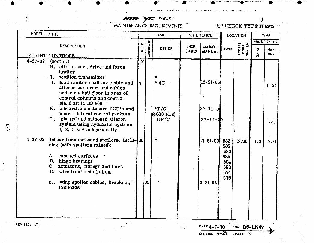
. .... 6 ......... 6 .................._- .............. 6 ......................, ................ _ ....................e ..........._.........O ...................• ..................• --
"2
.... • " •MAINTENANCE REQUIREMENTS '_C"CHECK TYPE ITEI_ ""
MODEL: ALL TASK REFERENCE LOCATION TIME
uJ HRS& TENTHS
DESCRIPTION _ _ INSP. _IAINT. E_• _ g_ OTHER ZONE _j o° _ _ UAN• m CARD MANUAL u a
FLIGHT CONTROLS u --, .€ z _ MRS
4-27-02 (cont'd.) XH. aileronback driveand force
limiterI. position transmitter *J. load limiter shaft assembly and x * 4C 12-21-05
aileron bus drum and cables (. 5)under cockpit floor in area ofcontrol columns and controlstand aft to BS 460
K. inboard and outboard PCU's and *F/C .)9-11-0central lateral control package (4000 Hrs)
L. inboard and outboard aileron OP/C 27-11-( 0 (. 8)m system using hydraulic systems _ ,
l, 2, 3 & 4 independently.
4-27-03 Inboard and outboard spoilers, inclu- X * 27-61-0C 582 N/A 1.3 2.6ding (with spoilers raised): 585
682A. exposed surfaces 685B. hinge bearings 584C. actuators, fittings and lines 583D. wire bond installations 574
575E.. wing spoiler cables, brackets, X ,2-21-05
fairleads
•. ' ,_o. D6-13747 ""
• s_c;,o,4-27 Jp,_ 2
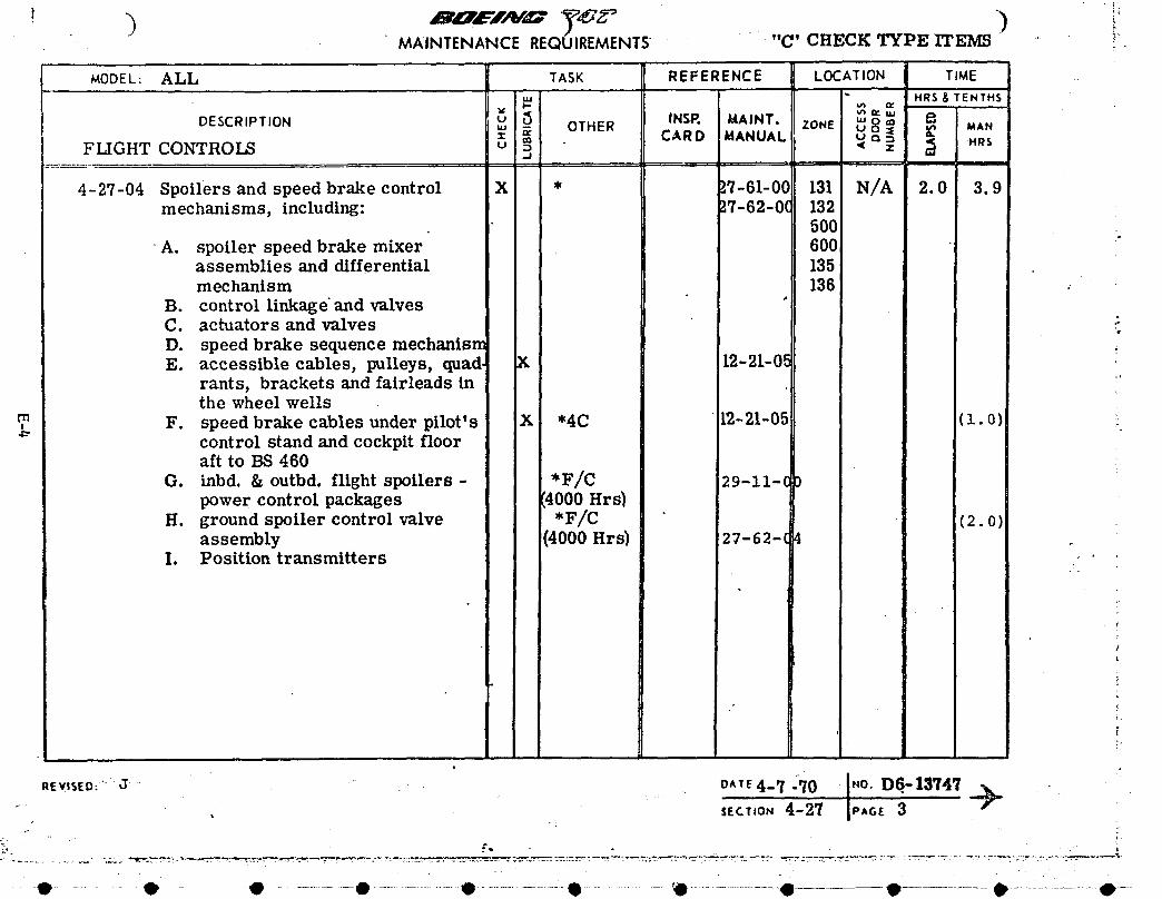
MAINTENANCEREQUIREMENTS "" "C" CHECK TYPE ITEMS ' i'
MODEL: ALL TASK REFERENCE LOCATION TIME=,,
uJ " HRS & TENTHSl-
DESCRIPTION u _5 INSP. MAINT. .RuJ - OTHER ZONE _, 8 _ _, _AN= '_ CARD MANUAL u ca--_rn
FLIGHTCONTROLS u _ _ z ;_ H.S..$
4-27-04 Spoilersand speedbrakecontrol X * _.7-61-00131 N/A 2.0 3.9mechanisms, including: ).7-62-0C132
i" 500'A. spoiler speed brake mixer 600
assemblies and differential 135mechanism 136 •
B. control linkage" and valvesC. actuators and valves ::D. speed brake sequence mechanismE. accessible cables, pulleys, quad, X 12-21-05
rants, brackets and fairleads in :'the wheel wells
F. speed brake cables under pilot's X "4C 12-21-05 (1.0) !:.control stand and cockpit flooraft to BS 460
G. inbd. & outbd, flight spoilers - *F/C 29-11-0 _power control packages 4000 Hrs}
H. ground spoiler control valve *F/C (2. o)assembly (4000 Hrs) 27-62-( 4
I. Position transmitters
REv,sEO:.....a ,- , O^TE4-'/ )10 1"O. O6.-13'/4'/. SECT,O.4-2'/ Is'.c.F.3 I
•_-e...... O - • ............. • .....................,D ...................:-@ ...... _l!..................• • • ....... :--: ....0--

• @ @.............. Q....................O...................., ................\e ......... .... @......................O-..............--_ ................• ................ .......................... ,.o_
MAINTENANCE REQUIREMENTS "C " CI_1_.C'KT'_I_. ITEMS
MODEL: ALL TASK REFERENCE LOCATION TIMEu,I
_ _ HR$ L TEt;TH!v e[ v* n,,DESCRIPTION u u INSP, MAINT. '" o m 8
. _, - OTHER ZONE uo• _,r " MANm CARD MANUAL u o -,FLIGHT CONTROLS u :_ ....j '( z ' _ HR$
4-27-05 Wing flap instal3ation, trailing X * !7-51-005/67 N/A 2.0 8.0edge, left and right, including: 5/67
5/67A. fore, mid and aft flap 5/68_
exterior surfaces and fair- !5/687ings 5/68 3
B. flap tracks,.rollers and 5/67 )carriages 5/68 )
C. flap rub strips and sealsD. inbd & outbd carriage
fittings
NOT APPLICABLE ON SPrnI
4-27-05 Wing flap installation, trailing X * 27-52-00 5/677 N/A 2.0 8.0edge, left and right, including: 5/68_
5/6 87A. inboard and outboard flap 5/67)
exterior surfaces and fair- 5/68)ings
B. flap crank arms,aft links: and fittings
C. flap rub strips and sealsD. inbd, center & outbd carrier
beam fittings
APPLICABLE TO SP ONLY
REv_SrU J
DATE 4-7-70 INa.D6-13747 +SEc.tlON4-27 PAGt"4i
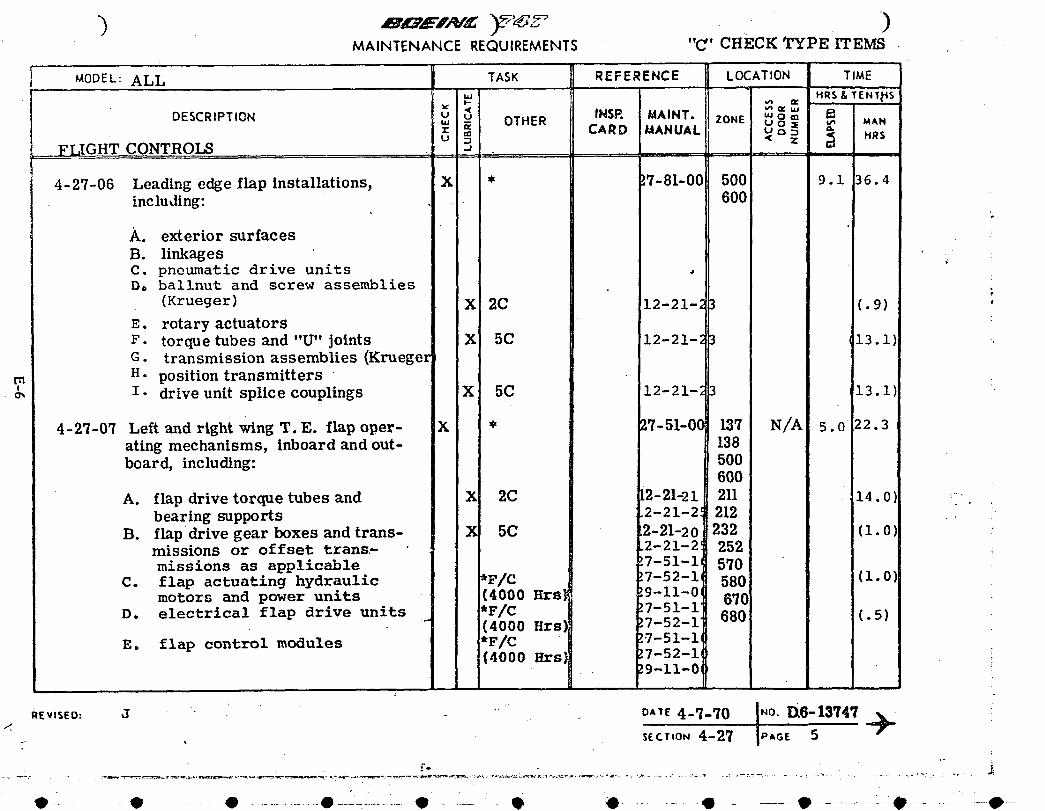
_,.TEN_CERCOU,,_E,,,,ENTS"c'c_zcz_Pz_E_MODEL: ALL TASK REFERENCE LOCATION TIME
_ HRS&TEN_t_S
DESCRIPTION _' u_ OTHER INSP. MAINT. ZONE _ o _ i_: CARD MANUAL o _ANm U 0 MRSU D Z
FLIGHT CONTROLS -J
4-27-06 Leading edge flap Installations, X * L7-81-00 500 9.1 36.4including: 600
A. exterior surfaces
B. linkages •C. pneumatic drive units •Do ballnut and screw assemblies
(Krueger) _ 2C 12-21-23 (.9)
E. rotary actuatorsF. torquetubesand"U"joints X 5C 12-21-_ 3 13.I) .G. transmissionassemblies(Krueger
m H. position transmitters ' •. o, I. driveunitsplicecouplings X 5C 12-21-_3 13.1
4-27-07 Left and right wing T.E. flap oper- X * 27-51-00 137 N/A 5. o 22.3ating mechanisms, inboard and out- 138board, including: 500
600
A. flap drive torque tubes and _ 2C i2-21-21 211 14.0 :
bearingsupports 2-21-2! 212 ,: "B. flap drive gear boxes and trRns- X 5C .2-21-20 232 (i. 0 "
missionsor offset trans:- 2-21-2! 252missions as applicable !7-51-1, 5q0
C. flap actuating hydraulic _F/C !7-52-i, 580 (i.0motors and power units (4000 Hrs| _9-ii-01 6q0
D. electrical flap drive units *F/C !7-51-1"" (4000 Hrs] !7-52-1 680 (.5)
E. flap control modules *F/C 2.7.51-11(4000 Hrs] 27-52-1
. !9-11-0'
,_,,_o:_ -- ,, " o,,_4-7-_ol.o.n6-,3_,_9-"_ - • SECTION 4-2_ IPAGE. 5
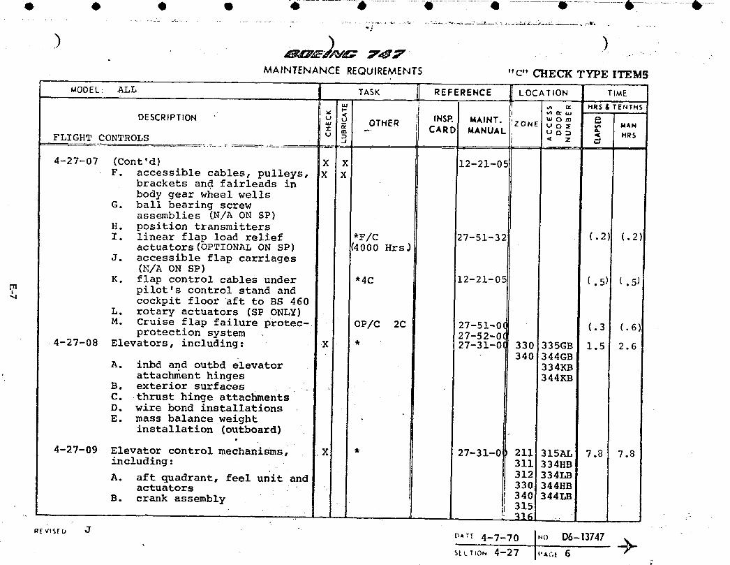
MAINTENANCE REQUIREMENTS "C" CHECK TYPE ITEMS
i ._.,
MODEL: ALL TASK REFERENCE LOCATION TIME
. ,, ,,_= _ H_'S;'TE,_THSDESCRIPTION " u _u INSP. MAINT. "' o m .P.
" - OTHER ZONE' u o • ,,, UAN= = CARD I MANUAL u _ D
FLIGHT CONTROLS u _ _ z _. MRS.J _a
[
4-27-07 (Cont'd) X X 12-21-05IF. accessible cables, pulleys, X X
brackets and fairleads inbody gear wheel wells
G. ball bearing screwassexLblies[N/A ON SP)
H. position transmittersI. linear flap load relief *F/C 27-51-32 (.2) (.2)
actuators(OPTIONALON SP) (4000Hrs_J. accessible flap carriages
(N/A ON SP)K. flap control cables under "4C 12-21-05 (.5) (.5)
,rn pilot's control standandcockpit floor aft to BS 460
L. rotary actuators (SP ONLY)
M. Cruise flap failure protec- OP/C 2C 27-51-0( (.3 (.6)protection system 27-52-0(
4-27-08 Elevators, including: X * 27-31-0! 330 335GB 1.5 2.6
A inbd and outbd elevator 340 344GB• 334KBattachment hinges 344KB
B. exterior surfacesC. thrust hinge attachmentsD. wire bond installationsE. mass balance weight
installation (outboard)
4-27-09 Elevator control mechanisms, X * 27-31-0 211 315AL 7.8 7.8including: 311 334HB
A. aft quadrant, feel unit and 312 334LBactuators .. 330 344HB
B. crank assembly 340 344LBifj315"-,, "_1 i_ I ".
,Ev,sru J . D,T.r4-7-70 IN()D6-13747S[L_,ON4--27 P*-,e 6
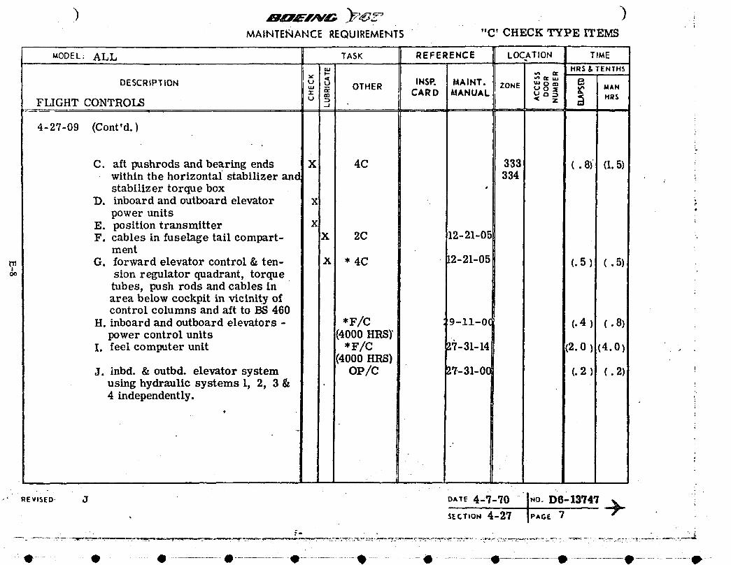
MAINTENANCEREQUIREMENTS"- "C' CHECK TYPE ITEMS
uODEL: ALL TASK REFERENCE LOCATION TIMEHRSX, TENTHS
DESCRIPTION _ _< _ TM ''='u INSP. MAINT. f_
_, _ OTHER ZONE _ o8_ _, MANm CARD MANUAL <u HR$FLIGHTCONTROLS u o..2
4-27-09 (Cont'd.) _,
C. aftpushrodsand bearingends X 4C 333 (.8) (I.5)within the horizontal stabilizer and 334 _.stabilizer torque box •
D. inboard and outboard elevator x _,power units "
E. position transmitter X "F. cables in fuselage tail compart- X 2C 12-21-05 _.
ment
G. forward elevator control & ten- X * 4C 2-21-05 (. 5 ) (.5) :sion regulator quadrant, torquetubes, push rods and cables inarea below cockpit in vicinity ofcontrol columns and aft to BS 460
H. inboard and outboard elevators - *F/C 9-11-0((.4) (. 8)power control units (4000 HRS)"
I. feel computer unit *F/C 1;/-31-14 (2.0) (4.0)(4000 HRS)
J. inbd. & outbd, elevator system OP/C 17-31-00 (. 2 ) (. 2)using hydraulic systems 1, 2, 3 &4 independently.
o,..4-7-o i.o.v6'ls7479"• SECt,o,,,4-27 IP,GE 7
._:--.T-- - ._,?JIF
o ' - • • ............. • ............ - • .................@............. • ............... • • ............. • ..................--qP....
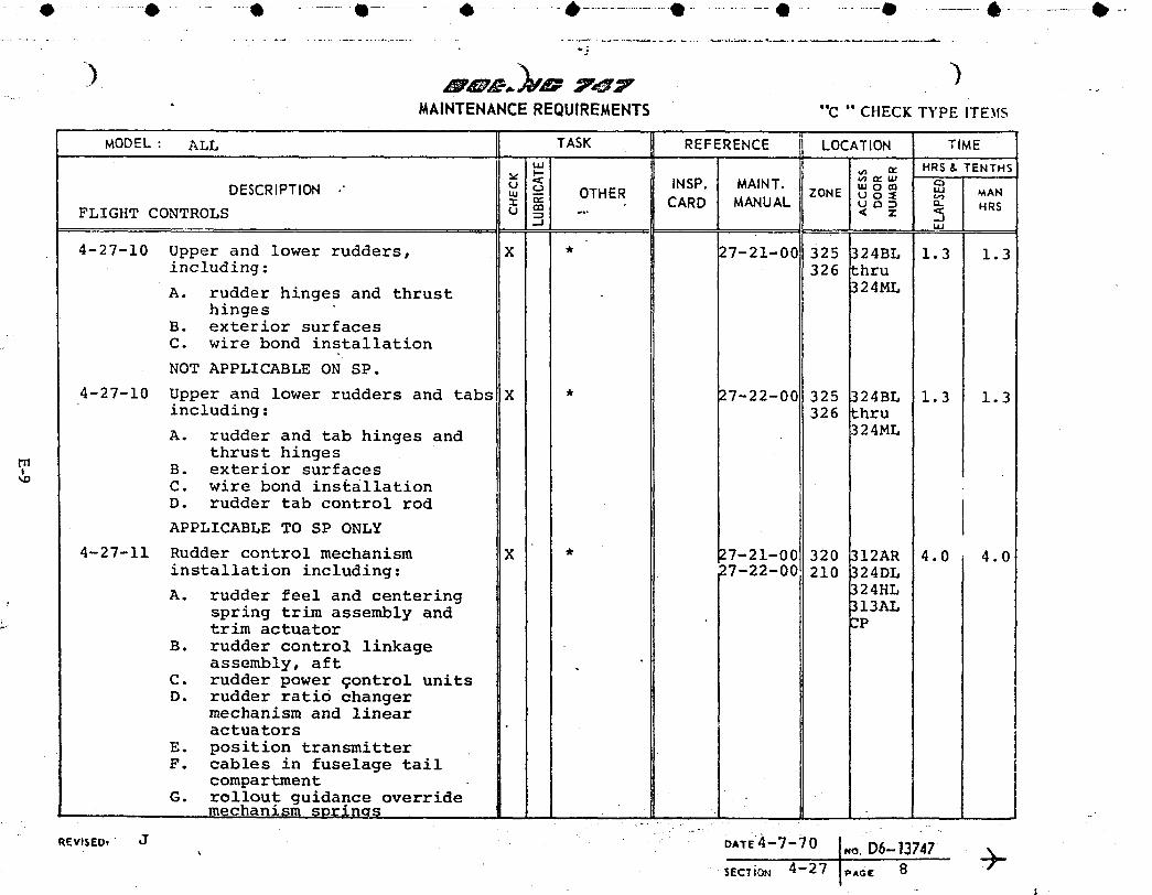
- O ....... • ......... O........................! .................O.....................• ......................e ..................e .......................O..................0 ............. _-................... • ...... . .......................... .. ..
"2
• MAINTENANCEREQUIREMENTS "c " CHECKTYPE iTE._IS
MODEL: ALL TASK REFERENCE jj LOCATION TIMEn_
u., HRS & TENTHS
< INSP. MAINT. '" o ,',,DESCRIPTION " u o u.J MAN' -, - OTHER ZONE U O :=E u._z ,,,,"" CARD MANUAL u "_ :D n HRS
FLIGHT CONTROLS u _ -. < z..... LU
4-27-10 Upper and lower rudders, X * 27-21-00 325 324BL 1.3 1.3including: 326 thru
A. rudder hinges and thrust 324MLhinges
B. exterior surfacesC. wire bond installation
NOT APPLICABLE ON SP.
4-27-10 Upper and lower rudders and tabs X * 27-22-00 325 324BL 1.3 1.3including: 326 thru
A. rudder and tab hinges and 324MLthrust hinges
B. exterior surfacesC. wire bond installationD. rudder tab control rod
APPLICABLE TO SP ONLY
4-27-11 Rudder control mechanism X * 27-21-00 320 312AR 4.0 4.0installation including: 27-22-00 210 324DL
A. rudder feel and centering 324HLspring trim assembly and _I3ALtrim actuator 3P
B. rudder control linkageassembly, aft
C. rudder power qontrol unitsD. rudder ratio changer
mechanism and linearactuators
E. position transmitterF. cables in fuselage tail
compartmentG. rollout guidance override
mechanism "sorln(_s
. i.o.D6_,3747
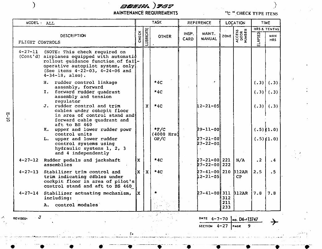
) i>MAINTENANCEREQUIREMENTS "c "CHECK TYPE ITEMS
'11
MODEL: ALL TASK REFERENCE II LOCATION TIMEHRS& TENTHS
< INSP. MAINT. _ _ _womDESCRIPTION u _ _ MANw -- OTHER ZONE U o= _ CARD MANUAL u _ : _ HRS
FLIGHT CONTROLS u m < z <
4-27-11 (NOTE: This check required on(Cont'd) airplanes equipped with automati
rollout guidance function of fai -operative autopilot system, only •(See items 4-22-03, 4-24-06 and4-34-18, also).
H. rudder control linkage "4C " (.3) (.3)assembly, forward
I. forward rudder quadrant "4C (.3) (.3) 'assembly and tensionregulator
J. rudder control and trim X "4C [2-21-05 (.3) (.3)cables under cokcpit floorin area of control stand and
o forward cable quadrant andaft to BS 460
K. upper and lower rudder powr *F/C 29-11-00 (.5)(1.0)control units (4000 Hrs
L. upper and lower rudder OP/C 27-21-00 (.5)(1.0)control systems using 27-22-00hydraulic systems I, 2, 3and 4 independently >
4-27-12 Rudder pedals and jackshaft X "4C 27-21-00 221 N/A .2 .4assemblies 27-22-00 222
4-27-13 Stabilizer trim control and X X "4C 27-41-00 210 ]I2AR 2.5 .5trim indicating cdbles under L2-21-05 CPcockpit floor in area of pilot's {control stand and aft to BS 460.._
4-27-14 Stabilizer actuating mechanism, X * !_-41-00 311 312AR 7.8 7.8including: 312
" " 211A. control modules ?" " 233
J " " " 4-7-7o1.0.06=,3747 -I
SECTION 4-27 {p,,o,_ 9
-° •_.z_
-O........• - -• - • ...........el..............._ .......e- " --e • e @-
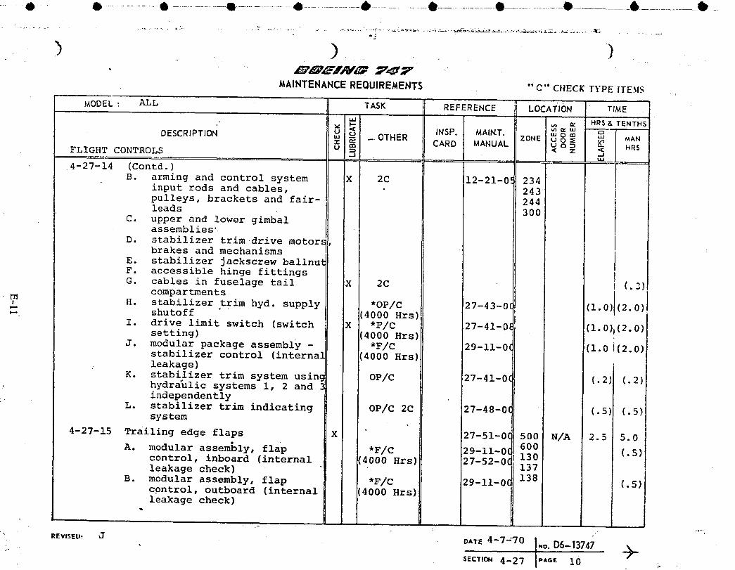
..... 0 0 ............. 6 .................• ......................6 ..................• .......................• • 0 -6............... • _
e:
> ) )
MAINTENANCEREQUIREMENTS "'¢" CHECK TYPE ITESlS
MODEL : ALL TASK REFERENCE " LOCATION TIME• I.I.J
, v ,,_1-- _ _., _ HRS & TENTHDESCRIPTION u o tNSP. MAINT. "' o = ,.,
"' -- OTHER ZONE U 0 _ MAN= _ - CARD MANUAL u a _ _-FLIGHT CONTROLS o =_ < Z < HR$
.-I .-J,., [
4-27-14 (Contd.) ' IB. arming and control system X 2C 12-21-0. = 234
Iinput rods and cables, 243 ipulleys, brackets and fair- 244leads 300
C. upper and lower gimbal
assemblies' iD. stabilizer trim drive motors,
brakes and mechanisms
E. stabilizer jackscrew ballnutF. accessible hinge fittings
G. cables in fuselage tail X 2C (.3)
compartments IH. stabilizer trim hyd. supply *OP/C 27-43-0( (i.0)(2.0)_. shutoff I(4000Hrs)
I. drive limit switch (switch X *F/C 27-41-0_ (1.0)i(2.0)setting) (4000 Hrs)
J. modular package assembly - *F/C 29-11-0( (i.0i(2.0)stabilizer control (internal (4000 Hrs)leakage)
K. stabilizer trim system usinc OP/C 27-41-0C (.2) (.2)hydraulic systems i, 2 and ._
:.. independently
L. stabilizer trim indicating OP/C 2C 27-48-0C (.5} (.5)system
4-27-15 Trailing edge flaps X 27-51-0( 500 N/A 2.5 I_.0A. modular assembly, flap *F/C 29-11-0( 600
control, inboard (internal 4000 Hrs) 27-52-0( 130 [.5)leakage check) 137
B. modular assembly, flap *F/C !29_ii_0( 138 (.5)cpntrol, outboard (internal 4000 Hrs)leakage check)
REVISED, J OATE4-7-30 .o. D6-13741
SECTIO.4-27 .A_E i0

,_,,MAINTENANCEREQUIREMENTS " C" CHECK TYPE ITEMS
................ _........ J_OD E L : AL n TASK _ m REFERENC E mLocA_ ON ........ T , . _
' "-"i _ INSP. MAINT. "' o "_
J DESCRIPTION u ,o OTHER ZONE _0o :_ _ MANI _ CARD MANUAL u ,', _ n.
FLIGHT CONTROLS O'_= < z l _ I HRs.. , -J _4-27-15 (Cont'd)
I C. power package assembly, fla] *F/C .)9-11-00 (.5) _• a i
drives, inboard and outboarc (4000 Hrs _.
D. alternate drive motor, T.E. *F/C .)7-51-17 (.5) iflap (check system) (4000 Hrs 7-52-17
4-27-16 Transmitter, flap position and X J *F/C 7-32-00 221 JN/A 4.0 :stall warning (asymmetry, stall . 7-58-00 500 I iwarning system calibration) 600 J(DELETE STALL WARNING ON SP) t
4-27-17 Over-rotation warning system X i *F/C 7-35-00 118 IN/A .5 _.(4000 Hrs 220 l
; . . 700 I_' 4-27-18 Trailing edge drive transmissiolX J * _7-51-00 570/_0 N/A 6.0 48.0
and ball bearing screw assembly, " backlash !7-51-33 670/_0check 17-51-41
inboard and outboard (8 units) I (9000 HrsZNOT APPLICABLE ON SP
4-27-19 Forward rudder quadrant assembl, K I * '7-21-00 211 1211G 1.0 2.0and tension regulator index !7-21-06
' check(9000 Hrs)
4-27-20 Forward elevator control and ( J * 17-3.1-00211 J211C 1.0 2.0 itension regulator quadrant , index 17-31-05i
' check • " ?I
" ; (9000 Hrs)
4-27-21 Cable inspection, including ( IX * 20-11-03 3001 N/A 1.5 3.0vertical fin and horizontal I 9000 Hrs) ]2-21-05 ;stabilizer -protected area.
a°
REVnSEU, J DATE 9--14--73 .o_D6-13747
. SECt"ION 4-27 I,,A_E 11 it
.... O...... e " • ........... O O..................qlP'.................O............ O O, 9 e--"
0!I
QiI
i APPENDIX F
II
O1 DELAY/CANCELLATION COST ALGORITHME
1
Costs associated with flight delays and cancellations are difficult to measure. The1
F following algorithms, based on airline industry cost estimates, used such factors as
i number ol passenger seats and average flight length.
Ii
o
!1
i
li
Ii
J
1
oi1I
i
o

Q
i
O
Delays
For design study purposes delay costs c_n be considered
as consisting of:
Passenger handling costs
Extra crew costs
Lost passenger revenue •
No satisfactory method has been developed to include any
loss of goodwill which results from a delay. Delay cost
may be calculated from the formula:
DC = (PHC + ECC + LPR) •
x SQA x DPC x ADM x UTIL x NA x CPC/(AFLH x 6000)
where:
DC = Delay cost dollars/year/fleet
PHC = Passenger handling cost, $'s/seat delay hour
PHC (76) = 0.2171
ECC = Extra crew cost,$'s per seat delay hourI
ECC(76) = 2.442- 0.0038 SQS
LP_ = Lost passenger revenue
($ per seat delay hour)
iP_(76) = (LF x {27.5689 AFLH - 1.373] •
x .8712 EXP(.0U5_ - .2271 AFLH))/
{I + I.3877 AFLH)
S_S = Seat quantity •
LFR = Load factor (deciKal, not _)
F-2 •

SQA = Seat quantity, ac-.ual
DPC = Delays per 100 flights
ADM = Average delay ti_e _er delay (_.inutes)
UTIL = Utilization zn hours per year per airplane
NA = Number of airplanes in the fleet
. AFiH = Average flight length (hours)
• L_C = Delay rate correction factor
F x DAFL ._ F x DAFLDRC _ DAFL 1
AFLH (FxDAFL)+I-FJ+- (F'xDAFL)+ 1-F
oDAFL = Average flight length _hours) associated
with DPC
Q , F = Flight hour/flight cycle factor for one
•_-!"_ hour flight from Figure I
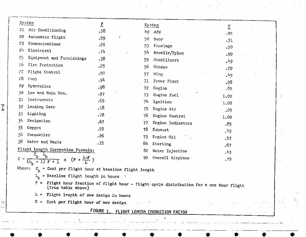
21 Ai1"Conditioning .58 1,9 APU .9022 AutomaticFlight .59 " 92 Door .5123 CommLu,icatlons .66 53 Fuselage .50
21_ E].ectrical .74 51_ A'aeelle/Pylon .90
2_ Equipmentand Furnishings .38 55 Stabilizers .I19
1'6 Flrc Pl'otection .25 56 l!Jndow .9027 F]ir,hL Control oo
• -_- 5"/' l;in(_ .I'9
;:8 l'_,el .9_ 71 Pc_terPlant .o8
29 F<Idraulics .98 72 Engine .89
30 Ic_:and R,_in Hem. .97 73 E_Igine Fuel ' i.O0
31 instruments .65 7h Ignition 1.00
32 LandingGear .18 75 E,igineAir .29
33 Lighting .'[8 76 F.ngineControl 1.00
31_ r:avi_ation .67 77 Engine Indicotors .8.5
35 O_gen .55 78 Exhaust .I15
36 Fne_Imtics .26 79 ErlgineOil .57
38 Water and l_aste .33 80 Starting .67
FlightLe1_th CorrectionFormula: 82 Water Injection .45cb Lb
C = _ 99 Overall Airplane{Lb-1)_'_ix (F+ ) .78Where: Cb = Cost per flight hour at bP.sellneflight length
Lb = Baselineflight lengthin hours
F = Flight hour fractionof flighthour - flightcycle dlstrlbutlcnfor a one hour flight(from table above)
L = Flicht length of new designin hourst[
C = Cost per flight hour of new design
FIGURE1. FLIGHTLENGTH£ORRECTIONFACTORI
• D • • • € € • • • •

O
Oi
i Cancellations
I Cancellation costs consist of all the costs of a delaye
up to the time at which a flight is cancelled plus costs
associated with loss of use of the airplane for the flight
hours it is out of service. Calculation of the delay
0 cost portion of cancellations is based on the average
delay time preceding a cancellation, ADMC.
CN = (CNDC + CNDL) x CNPM x UTIL x NA/(1000 x AFLH)
where:
CN = Cancellation dollars/year/fleet
Q CNDC = Cancellation delay, $'s/cancellation
CNDL = Cancellation downtime, $'s/cancellation
CNPM = Cancellations/1000 departures/airplane
I UTIL = Utilization flight hours/year/airplanei
i NA = Number of airplanes in the fleet
B AFLH = Average flight length in hours
Cancellation, Delay Cost Contribution
• CNDC = (PHC + ECC + LPR) x SQA x ADMC x DRC/60
where:
ADMC = Average delay minutes preceding cancellation
= 25 + 35.2 x AFLH
AFLH = Average flight length in hours
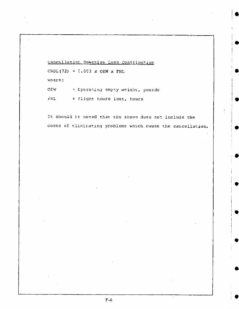
Cancellatior Down__i_e Loss Contribution
CNDL(72) = C.0C3 x OEW x FHL 8
wnere :
OEW = Gperating empty weigh_, pounds
r-H! = -light hours lost, hours
It should k£ noted that the above does not include the
costs of eli_.inatlng problems whlch cause the cancellation.
F-6 •

i
OiII
III
e I. Report NO. 2. Govelnment Acce,_sion No. 3. Reclplent'sCatalog No.
CR-1590104. Title and Subtitle 5. Repor! Date
B-747 Primary Flight Control Systems Reliability. APRIL 1979and Maintenance Study 6. Perfo,mlngOrganitationCode
I 7. Author(s) 8. Performing Organization Report No.
BCAC Product Assurance Unit D6-4633010. Work Unit No.
9. Performing Organization Name and Address
Boeing Commercial Airplane company (BCAC) I_ Contract or G,antNO.P.O. Box 3707 NASI-14742
O Seattle9 Washington 98124 13. Type of Report and Period Covered
12. Sponsorinq Aqency NameandAddress Contractor Report - Finali National Aeronautics and Space Administration AI IC, 1977 - 3ULY 19_7______i 14. Sponsoring Agency Code
i Washington, D.C. 20546TI 15. Supplementary Notes
This report covers work conducted under one of five tasks included ini Contract NAS1-14742.
i 16. Abstract
i The major operational characteristics of the 7#7 Primary Flight Control Systems) (PFCS) are described. Results of reliability analysis for separate control functions
are presented. The analysis makes use of a NASA computer program which calculatesi reliability of redundant systems. Costs for maintaining the 747 PFCS in airline service '
are assessed. The reliabilities and costs will provide a baseline for use in trade studiesof future flight control system design.
i
iII[I
i
O}
i1
17. Key Words (Suggested by Author(s) ) 18. Distribution Statement
Reliability FEDD DistributionMaintenance Cost747 PFCS
19. Security Classil. (of this report) 20. Security Classif. (of this page) 21. No. of Pages 22. Price"
Unclassified unclassified
AVAILABLE: NASA'S Industrial applications centers
G-I

J
O
