3-08 power factory hardware simulation-sce.pdf
TRANSCRIPT

Power Factory Hardware in the Loop Simulation
EPIC December Symposium December 1, 2016
Southern California Edison 1

Hardware in the Loop (HIL) Fundamentals • What?
‒ Hardware in the loop (HIL) testing is the process of placing a control system in an open or closed loop with a system/plant simulator to validate control system performance
• Why? ‒ Power system control elements and control systems
are complex, and increasing in complexity ‒ Correct operation of power system controls are
critical to maintain safety, reliability, and in some cases economic operation
‒ Scripting capabilities in the HIL simulator can run hundreds to thousands of scenarios in a few days
CONFIDENTIAL 2 Southern California Edison

Simplified HIL Diagram
Southern California Edison 3
Simulated Power Grid
Measurements
Control Signals
Control System Under Test
Measurements
Control Signals

Hardware in the Loop (HIL) Challenges • What are the challenges
‒ Fidelity: How much detail must be in the power system model in order to test the control system?
‒ Time Step: How fast must the model be simulating the power system? How fast must data be exchanged between the power system and control system?
‒ Interfacing with the control system: What protocols does the control system use? What physical interfaces does the control system and simulator use?
CONFIDENTIAL 4 Southern California Edison

Two Types of HIL Simulation • Electromagnetic Transients (EMTP) Δt = 50µs • Dynamic Stability (RMS) Δt = 0.01s
CONFIDENTIAL 5 Southern California Edison

Types of HIL Simulation • EMTP simulation is best suited for:
‒ Flexible Alternating Current Transmission System (FACTS)
‒ Protective relay testing ‒ Islanded microgrid control systems
• Dynamic stability simulation is best suited for: ‒ Energy management system (EMS) and distribution
management system (DMS) state estimator ‒ EMS / DMS visualization application ‒ SCADA based control applications
Southern California Edison 6

EMTP vs Dynamic Stability HIL Simulation • EMTP real time simulation is computationally
intense and often requires specialized simulation hardware
• EMTP simulation can be distributed across multiple simulators in transmission applications, but typically cannot be distributed in distribution applications
• Dynamic stability is less computationally intense and can be used to simulate transmission or distribution systems
• Dynamic stability can represent distribution systems in full fidelity compared to EMTP which require some level of simplification
CONFIDENTIAL 7 Southern California Edison

Power Factory Overview • Power Factory is a power systems analysis
software package for distribution, transmission and generation applications
• Power systems can be modeled in static, quasi dynamic, dynamic or in EMTP
• Power Factory has additional functions to support HIL applications ‒ Multiphase dynamic stability simulation in real time ‒ OPC client for real time applications
CONFIDENTIAL 8 Southern California Edison
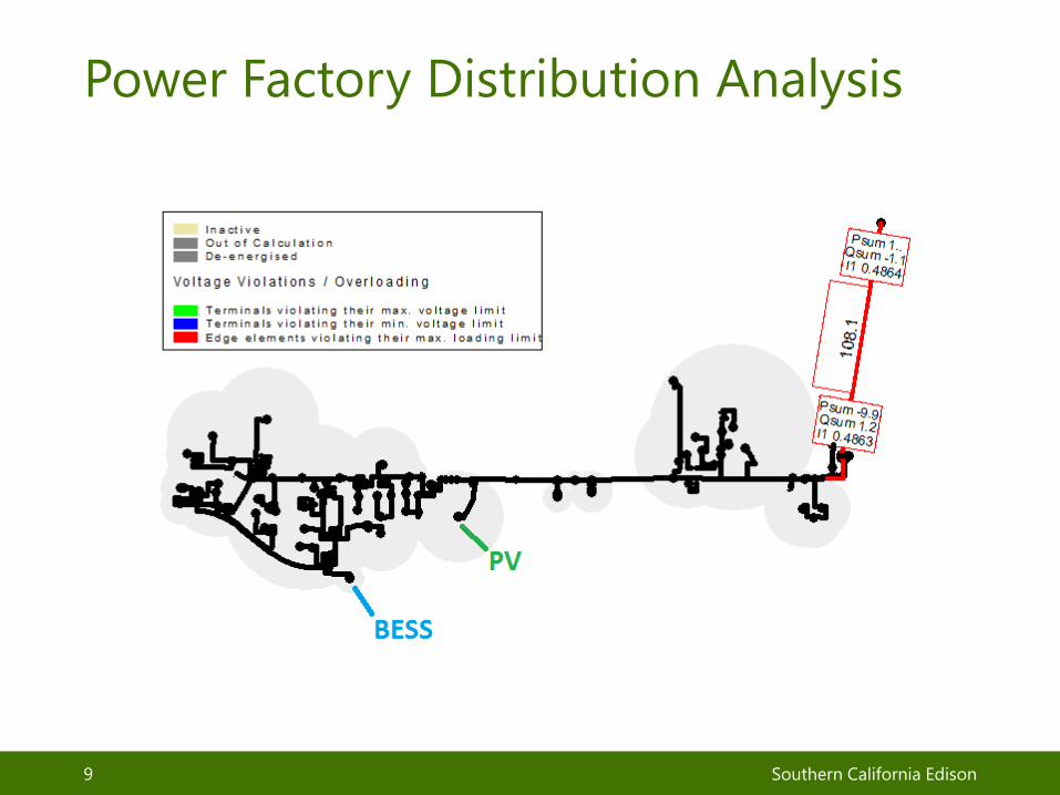
Power Factory Distribution Analysis
CONFIDENTIAL 9 Southern California Edison

Power Factory Real Time Simulation • Dynamic models can be added to the model to
capture the performance of power system components ‒ Loads can be changed over time based on historic
meter data ‒ Shunt capacitor banks can be set to switch based
on line voltage or from an external control signal ‒ Smart inverters on solar photovoltaic (PV) plants
can be set to inject or absorb reactive power or curtail active power
‒ Smart inverters on battery energy storage systems (BESS) can follow an real and reactive power reference signal, and manage the battery state of charge
CONFIDENTIAL 10 Southern California Edison
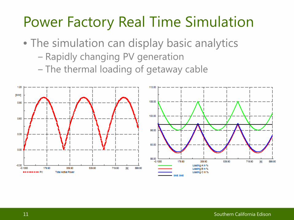
Power Factory Real Time Simulation • The simulation can display basic analytics
‒ Rapidly changing PV generation ‒ The thermal loading of getaway cable
CONFIDENTIAL 11 Southern California Edison
Power Factory External Data Link • Power Factory has an OPC client can establish a
connection with an external OPC server • An OPC tag can be created for nearly every
measurement point, or control point • For example:
‒ Measured current and power at the feeder circuit breaker
‒ Switch status, and switch control ‒ Control of active power from a dynamic BESS model
CONFIDENTIAL 12 Southern California Edison

Triangle Microworks SCADA Gateway • OPC is a very common protocol, but few field
and substation devices in SCE’s system use this protocol
• Most field and substation devices use DNP3, Modbus, 61850 GOOSE, or 61850 MMS ‒ 61850 GOOSE typically used for protection, but for
applications related to monitoring or slower control it can be used in the Power Factory Simulation
• The solution is to use a protocol translator, Triangle Microworks SCADA data gateway to translate between OPC and other protocols
Southern California Edison 13

Physical Connection • The Triangle Microworks SCADA Data Gateway
runs on a dedicated server with four physical Ethernet interfaces
• IP addresses are configured in the ‘Ethernet Adapter Settings’ in the Windows server so that the device created in Triangle Microworks SCADA Data Gateway match with the physical interfaces
• The Power Factory / Triangle Microworks simulation system described can only communicate via Ethernet
Southern California Edison 14

Hardware mapping
Southern California Edison 15
Windows Server
Ethernet 0
Ethernet 1
Ethernet 2
Ethernet 3
Triangle Microworks SCADA Data Gateway • OPC Connection to
Power Factory • Substation VLAN • Field VLAN
Substation VLAN
Field VLAN
OPC to/from Power Factory
IP R
outin
g Ta
ble

Application – Distribution Management System (DMS) • Test state estimation accuracy and the
improvements gained by adding more measurement points ‒ Historic meter data is ‘played back’ through Power
Factory ‒ Compare DMS state estimation with actual values in
Power Factory ‒ Add additional measurement points to DMS and
measure the improvement ‒ Scenarios of interest include determining optimal
number and location of measurement points and impact on feeders with high amounts of PV on days with intermittent cloud cover.
Southern California Edison 16

Application – Distribution Management System (DMS)
Southern California Edison 17
The end result is the power flow in DMS driven by the power factory simulation
Power Factory measures the total feeder current and reactive power
TMW creates a DNP Server that appears like the substation HMI
The DMS reads the SCADA points

Application – Optimal Power Flow • Test the control of an Optimal Power (real
power) Flow (OPF) controller ‒ Historic meter data and substation bus voltage is
‘played back’ through Power Factory ‒ The OPF controller should minimize the total cost of
operating the distribution feeder, while meeting all thermal and voltage constraints.
‒ Compare the operation of the OPF to status quo (no OPF) and quantify benefits
Southern California Edison 18

Application – Volt / VAR Control • Test the operation of a distribution volt / VAR
control system ‒ Historic meter data and substation bus voltage is
‘played back’ through Power Factory ‒ Verify that the control system maintains feeder
maximum VAR consumption and customer minimum voltage constraints while minimizing the voltage at each meter
‒ Compare the operation of the volt / VAR control to status quo (no volt / VAR controller) and quantify benefits
Southern California Edison 19

Application – Virtual Microgrid • Test the operation of a virtual microgrid
controller ‒ A virtual microgrid is radial section of a feeder with
a point of common coupling (PCC) with the rest of the feeder. The microgrid is still connected in parallel with the grid, however the control system works to maintain zero power flow through the PCC
‒ Load and generation can be ramped up and down, tripped offline, and reconnected – the microgrid controller should work to maintain zero power flow
‒ Due to the speed of the simulator and controller, events like motor inrush should not be adapted for by the microgrid controller
Southern California Edison 20

Wrap Up • Questions? Comments?
Southern California Edison 21