2d swbd 6.6 kv 110 vdc system documentation 47
DESCRIPTION
2D SWBD 6.6 LW 110 VDC SystemTRANSCRIPT

Copyright 2004 ABB AS. All rights reserved.
External doc. no. Based on Power One Doc No 031357D - D Project Samsung HN1554 British Gas LNG Prep. TE / Per Arind Berg 2005-04-05 Customer Samsung Heavy Industries Co. Ltd. Appr. MPE / Per Arind Berg 2005-04-05 Proj. no. P010540 Samsung HN1554 Doc. kind Acceptance Record Doc.
des. Ref. des.
Title 110V DC Complete Documentation Resp. dept TE Status Approved Doc. no. Lang. Rev. ind. Page 1
Automation Technologies Division
SAMSUNG HEAVY INDUSTIES CO Ltd.
Hull-1554
British Gas, LNG Carriers
Complete
110 VDC System documentation 6,6kV Switchboard
CUSTOMER STATUS CODES
1: APPROVED
WITHOUT COMMENTS
Rev. printed name:
2: APPROVED WITH COMMENTS (TO BE INCORPORATED)
Reviewers signature:
3: NOT APPROVED REVISE AND RESUBMIT
Discipline:
4: FOR INFORMATION
Review completion:
3AJM000282-035 en D No. of p. 47 FILE: 3AJM000282-035_00 Rev D 110V DC Complete Documentation.doc; SAVEDATE: 2005-04-05 20:22; TEMPLATE: TECHN_DOC_DELIV_P.dot A; SKELETON:

Doc. kind Acceptance Record Project Samsung HN1554 British Gas LNG Customer Samsung Heavy Industries Co. Ltd. Title 110V DC Complete Documentation Proj. no. P010540 Samsung HN1554 Doc. no. Lang. Rev. ind. Page 47
Automation Technologies Division 3AJM000282-035 en D No. of p. 47
REVISION Rev. ind. Page (P)
Chapt. (C) Description Date
Dept./Init.
- ALL For approval 2005-04-05 MPE/PEBE

Document list PPS 6.110E-3600/ABB01 Doc.No.: 031357d Rev.: D Page: 1 of 1 Prepared by: Anders Strand Date: 20.08.03
G:\CC\K-DOK\06\031357d.doc
DOCUMENTATION POWER SUPPLY SYSTEM
PPS 6.110E-3600/ABB01 Documents:
031341 System Description PPS 6.110E-3600/ABB01 Rev.: B 031356 Installation Guide PPS 6.110E-3600/ABB01 Rev.: B
Associated drawings: 026955 Cabinet Arrangement PPS 6.110E-3600 IP23 Rev.: / 026956 Cabinet Layout PPS 6.110E-3600/ABB01 Rev.: /
026957 Cabinet Installation PPS 6.110E-3600/ABB01 Rev.: / 026958 Battery Installation PPS 6.110E-3600/ABB01 Rev.: A 027081 Hawker Energy Battery Classification Rev.: / 026905 Connection Unit PPS 6.110E-3600/ABB01 Rev.: A 026980 Schematic Diagram PPS 6.110E-3600/ABB01 Rev.: / 024918 Connection of Temperature Probe and
Symmetry measurement for PPS 6.110E Rev.: / 027080 Configuration PCU 6.110E Rev.: / 025353 Distribution PDU 6.110E Rev.: /

System Description PPS 6.110E-3600/ABB01 Doc. No.: 031341b Rev.: B Page: 1 of 19 Prepared by: Anders Strand Date: 20.08.03
Approved by: Roar Fagerhus Date: 20.08.03 G:\CC\K-DOK\06\031341b.doc
SYSTEM DESCRIPTION POWER SUPPLY SYSTEM
1. GENERAL................................................................................................................................................... 2
2. TECHNICAL DATA .................................................................................................................................. 3
3. OPERATING - RECTIFIER..................................................................................................................... 4
4. OPERATING - CONTROL UNIT............................................................................................................ 6 4.1. GENERAL ............................................................................................................................................... 6 4.2. ADJUSTMENT OF PARAMETERS............................................................................................................... 7 4.3. TEST OF LED'S AND ALARMS ................................................................................................................. 7 4.4. BOOST CHARGING .................................................................................................................................. 8 4.5. BATTERY TEST ....................................................................................................................................... 8 4.6. EARTH FAILURE DETECTION................................................................................................................... 9 4.7. SYMMETRY MEASUREMENT- (OPTION) ................................................................................................ 10 4.8. TEMPERATURE COMPENSATED CHARGING-(OPTION) ........................................................................... 10
5. INDICATIONS-CONTROL UNIT ......................................................................................................... 11
6. OPERATION - SUBRACK...................................................................................................................... 12 6.1. SUBRACK PPR 6.00E........................................................................................................................... 12
7. DISTRIBUTION ....................................................................................................................................... 13
8. CABINET (TYPE TS 8605.600) .............................................................................................................. 13
9. BATTERIES.............................................................................................................................................. 16
10. ACTIONS AT ALARM CONDITION ............................................................................................... 17 10.1. LOW OUTPUT VOLTAGE.................................................................................................................... 17 10.2. HIGH OUTPUT VOLTAGE ................................................................................................................... 17 10.3. FUSE ALARM- (OPTION).................................................................................................................... 17 10.4. MODULE ALARM .............................................................................................................................. 17 10.5. MAINS FAILURE ............................................................................................................................... 17 10.6. EARTH FAILURE ............................................................................................................................... 17 10.7. SYMMETRY FAILURE- (OPTION) ....................................................................................................... 18 10.8. OVER VOLTAGE SHUT DOWN IN MODULE.......................................................................................... 18 10.9. MALL FUNCTION ON PCU 6.00E...................................................................................................... 18
11. MAINTENANCE.................................................................................................................................. 18
12. CHANGE OF EPROM......................................................................................................................... 19
System Description PPS 6.110E-3600/ABB01 Doc. No.: 031341b Rev.: B Page: 2 of 19 Prepared by: Anders Strand Date: 20.08.03 1. General 1.1. This documentation describes the power supply systems designated as:
PPS 6.110E-3600/ABB01
1.2. PPS 6.110E-3600/ABB01 is a power supply system of modular design which is based
on the following units: PMP 6.110 SIC - plug-in rectifier module, 110-129V/5A. PCU 6.110E - microprocessor based supervision unit, operation voltage
110V, with RS232/RS485 interface. PPR 6.110E/7 - subrack for 1 PCU 6.110E and max. 6 PMP 6.110 SIC. PDU 6.110E - distribution unit with fused outputs for battery and load. ESD and LVD - Emergency Shut-Down and Low Voltage Disconnection Rittal cabinet - Cabinet for floor mounting. WxHxD=600x2000x500mm Batteries - 9 valve regulated sealed batteries connected in series. 1.3. To simplify this documentation, the modules are described by the common names: Rectifier: PMP 6.00 SIC
Control module: PCU 6.00E Subrack: PPR 6.00E
1.4. The power supply system has been designed to meet the requirements in today's
modern power supply systems with high reliability, high flexibility, simple installation and simple use/maintenance. Because of the system modularity, the system can be configured according to present requirements, and easily be expanded to future requirements.
1.5. The system has protective and supervisory circuits for completely automatic operation.

System Description PPS 6.110E-3600/ABB01 Doc. No.: 031341b Rev.: B Page: 3 of 19 Prepared by: Anders Strand Date: 20.08.03 2. Technical data 2.1. Input
• Voltage: 230V AC single phase or 230/400V AC 3-phase, +/-20% • Current: Max. 4A/230V AC single phase per PMP-module • Power factor: >0,98 at 50-100% load
2.2. Output
• Voltage: 110V DC nominal • Current: max. 5A per PMP-rectifier • Total current: max 15A (3 rectifiers) • Power: max. 1800W (3 rectifiers)
2.3. System specification
• Enclosure: Minimum IP 23 • Weight: Approx. 185kg without batteries • Cooling: Natural convection cooling • Construction: Welded frame with external and internal walls • Size: 600x2000x500 (WxHxD)
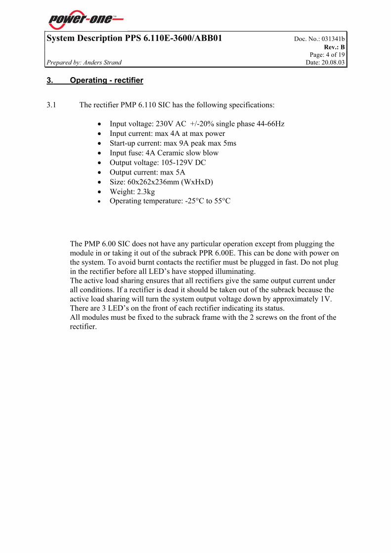
System Description PPS 6.110E-3600/ABB01 Doc. No.: 031341b Rev.: B Page: 4 of 19 Prepared by: Anders Strand Date: 20.08.03 3. Operating - rectifier 3.1 The rectifier PMP 6.110 SIC has the following specifications:
• Input voltage: 230V AC +/-20% single phase 44-66Hz • Input current: max 4A at max power • Start-up current: max 9A peak max 5ms • Input fuse: 4A Ceramic slow blow • Output voltage: 105-129V DC • Output current: max 5A • Size: 60x262x236mm (WxHxD) • Weight: 2.3kg • Operating temperature: -25°C to 55°C
The PMP 6.00 SIC does not have any particular operation except from plugging the module in or taking it out of the subrack PPR 6.00E. This can be done with power on the system. To avoid burnt contacts the rectifier must be plugged in fast. Do not plug in the rectifier before all LED’s have stopped illuminating. The active load sharing ensures that all rectifiers give the same output current under all conditions. If a rectifier is dead it should be taken out of the subrack because the active load sharing will turn the system output voltage down by approximately 1V. There are 3 LED’s on the front of each rectifier indicating its status. All modules must be fixed to the subrack frame with the 2 screws on the front of the rectifier.

System Description PPS 6.110E-3600/ABB01 Doc. No.: 031341b Rev.: B Page: 5 of 19 Prepared by: Anders Strand Date: 20.08.03
POWER ONGreen LED indicating that the rectifierand the input voltage is OK
O.V. SHUT-DOWNSelective shut down of rectifier causedby too high output voltage
ALARMModule failure, low output DC ornon equal load sharing
If mains is interrupted no LED’s will illuminate
Upper fixing screw
Lower fixing screw
Handle
PMP 6.110 SIC front

System Description PPS 6.110E-3600/ABB01 Doc. No.: 031341b Rev.: B Page: 6 of 19 Prepared by: Anders Strand Date: 20.08.03 4. Operating - control unit
4.1. General
4.1.1. The internal control unit, PCU 6.00E, supervises and monitors the system. The system is designed to be used with PCU 6.00E. If mall function in the control
module occurs, this will cause no effect to the system. 4.1.2. The PCU 6.00E is a microprocessor based control unit for supervising PMP 6.00 SIC
modules mounted in the subrack PPR 6.00E. The control unit supervises current, voltage and condition from each module in the subrack and can supervise and control external functions as input mains, earth failure, load disconnection, etc.
4.1.3. The unit has two LCD’s showing current and voltage, 3 digits reading.
4.1.4. The control unit PCU 6.00E measures the data continuously. Measurements are
compared to the reference values in the software. 4.1.5. Press "SELECT". The ammeter is connected to the module positions and measures the module current
from the module that is indicated by a flashing LED on the front of the PCU 6.00E. When "TOTAL" illuminate, the ammeter is indicating the total current from all
rectifiers. When "BATTERY" illuminates the ammeter is indicating the battery current. A
green LED indicates positive battery current (charging), negative battery current (discharging) is indicated by yellow LED.
4.1.6. The PCU 6.00E is based up on an 8097 microprocessor and has a serial interface,
RS232/RS485 for communication with an external computer. The unit has 5 potential free alarm contacts for external signalling of single alarms or groups of alarms. See the “Configuration PCU 6….” sheet for details.

System Description PPS 6.110E-3600/ABB01 Doc. No.: 031341b Rev.: B Page: 7 of 19 Prepared by: Anders Strand Date: 20.08.03 4.2. Adjustment of parameters 4.2.1. By pressing " " (adjust) and " " (enter) at the same time, adjustment of alarms can
be done. A yellow LED will flash for indication of which level to be adjusted. V-meter displays output voltage and A-meter displays the set level. Adjustment up or down is made by holding " « down and press " " (up) or " " (down).
Float charge U1 123.1V Low DC voltage 106V High DC voltage 129V Battery disconnect 97.2V Boost time (OPTION) 0h Boost charging (U2) (OPTION) 0V Earth resistance 100kΩ 4.2.2. Press " " or " " for the next or previous alarm. 4.2.3. By pressing " " and " " the adjustment is confirmed.
4.3. Test of LED's and alarms 4.3.1. By pressing " " and "SELECT", a test of LED's and alarms are activated. All LED's
will illuminate (yellow) and the first alarm is activated. The lower display on the control unit will show the following:
Push Shown in the
lower display Description
1 « » and «SELECT» E1 Alarm 1 activated 2 « » and «SELECT» E0 No alarm activated 3 « » and «SELECT» E2 Alarm 2 activated 4 « » and «SELECT» E0 No alarm activated 5 « » and «SELECT» E3 Alarm 3 activated 6 « » and «SELECT» E0 No alarm activated 7 « » and «SELECT» E4 Alarm 4 activated 8 « » and «SELECT» E0 No alarm activated 9 « » and «SELECT» E5 Alarm 5 activated 10 « » and «SELECT» - End of test
If the test is started and not ended, the test will automatically end after 10 minutes.

System Description PPS 6.110E-3600/ABB01 Doc. No.: 031341b Rev.: B Page: 8 of 19 Prepared by: Anders Strand Date: 20.08.03 4.4. Boost charging 4.4.1. Boost charging of batteries: Press " " " " until a yellow LED starts to illuminate for "BOOST CHARGE", and
yellow LED's start to illuminate for "MODULE" 4.4.2. Press " " " " to interrupt the boost charging. 4.4.3. Output voltage will increase to U2, and automatically return to float charge after set
time. 4.4.4. See configuration sheet, for information regarding boost charging and interval. 4.4.5. Automatic and periodic boost charging is adjusted from PC with PowCom. NOTE! Valve regulated batteries shall not be boost charged.
4.5. Battery test 4.5.1. The battery test can be activated from PC with PowCom or from PCU 6.00E. Output
voltage will decrease to pre-set value and logging of battery voltage, battery current and Ah starts. The test will be interrupted when one of these terms, pre-set from PowCom, are fulfilled: Test time, Ah or end voltage.
Programmed data, adjustable from PC with PowCom: end voltage, time, Ah, symmetry deviation.
4.5.2. Press "SELECT" until a green LED starts to flash for MODULE. Press " " and " " until a yellow LED's start to illuminate for all modules in the
group. Battery test is activated. The duration of the test is pre-set from PowCom, or the test can be stopped manually
by pressing " " and " ". 4.5.3. Battery test can also be activated automatically 1-4 times a year. Select no. of tests
with PowCom. 4.5.4. Connect a PC to the data bus for transmission of battery test data, including
information of the time test started. Test data from the last 10 tests will be saved. The measurement will automatically be started at mains interrupt above a certain time. 4.5.5. NOTE! Depending on the pre-set level of low output voltage alarm, the alarm may be
displayed during the battery test. This is only an internal indication and it will not affect the output alarm relays during the test, and one minute after reset of test.
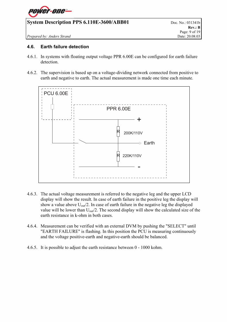
System Description PPS 6.110E-3600/ABB01 Doc. No.: 031341b Rev.: B Page: 9 of 19 Prepared by: Anders Strand Date: 20.08.03 4.6. Earth failure detection 4.6.1. In systems with floating output voltage PPR 6.00E can be configured for earth failure
detection. 4.6.2. The supervision is based up on a voltage-dividing network connected from positive to
earth and negative to earth. The actual measurement is made one time each minute. 4.6.3. The actual voltage measurement is referred to the negative leg and the upper LCD
display will show the result. In case of earth failure in the positive leg the display will show a value above Uout/2. In case of earth failure in the negative leg the displayed value will be lower than Uout/2. The second display will show the calculated size of the earth resistance in k-ohm in both cases.
4.6.4. Measurement can be verified with an external DVM by pushing the "SELECT" until
"EARTH FAILURE" is flashing. In this position the PCU is measuring continuously and the voltage positive-earth and negative-earth should be balanced.
4.6.5. It is possible to adjust the earth resistance between 0 - 1000 kohm.
PCU 6.00E
PPR 6.00E
+
-
200K/110V
Earth
220K/110V R
R

System Description PPS 6.110E-3600/ABB01 Doc. No.: 031341b Rev.: B Page: 10 of 19 Prepared by: Anders Strand Date: 20.08.03 4.7. Symmetry measurement- (Option) 4.7.1. Measurement of the symmetry voltage is done by dividing the battery bank into 3
"36V blocks". The voltage is measured over each separate block. If one of the measurements is different from the average voltage, alarm will occur.
4.7.2. The symmetry measurement is activated continuously in order to detect eventual
thermal runaway. 4.7.3. Max. 2 battery branches can be supervised by symmetry measurement. The number of
battery branches being supervised by symmetry measurement cables has to be set in PowCom in order to activate the symmetry measurement.
4.7.4. The sense cables measuring the symmetry voltage are short circuit protected by a PTC
resistance. In case of rearranging the cable it is very important to keep the PTC as close to the battery pole as possible.
4.7.5. In case of short circuit the PTC will increase its internal resistance to approx. 100K
and limit the current as a short circuit protection.
4.8. Temperature compensated charging-(Option) 4.8.1. By connecting a temperature probe to the system measuring the battery temperature,
the output voltage will be automatically adjusted. The compensation factor is pre-set from factory, but can be adjusted from a PC with PowCom. The temperature probe should be placed in a position measuring the average temperature of the battery bank. It is recommended to glue the temperature probe to the battery that is located in the middle of the topmost battery shelf.

System Description PPS 6.110E-3600/ABB01 Doc. No.: 031341b Rev.: B Page: 11 of 19 Prepared by: Anders Strand Date: 20.08.03 5. Indications-Control Unit
5.1. In normal condition, one of "MODULE 1-6", "TOTAL" or "BATTERY" will
illuminate, for indication of what current and voltage the v- and ammeter displays.
BATTERY TEST
TOTAL
TEMP. ALARM
BATTERY
EARTH FAILURE
MODULE 1MODULE 2MODULE 3MODULE 4MODULE 5MODULE 6
OPERATIONLOW VOLT. ALARMHI. VOLT. ALARMMODULE ALARMLOW VOLT. DISC.FUSE FAILUREMAINS FAILUREBOOST
LCD BATTERY TEST - Battery test on TEMP. ALARM – High temperature alarm EARTH FAILURE -Earth failure alarm LCD TOTAL - Total load current BATTERY - Battery current MODULE 1 - 6 Green - module OK Green flashing - module connected to A-meter Red - module failure Yellow - test or boost is activated SELECT - select functions OPERATION - Internal power in PCU 6.00E - OK LOW VOLT. ALARM - Low DC voltage HIGH VOLT. ALARM - High DC voltage MODULE ALARM - Failure in PMP module LOW VOLT. DISCONN - Battery disconnected FUSE FAILURE - Fuse alarm MAINS FAILURE - Mains failure BOOST - Boost charge activated U-OUT - Test outlet, NOT APPLICABLE

System Description PPS 6.110E-3600/ABB01 Doc. No.: 031341b Rev.: B Page: 12 of 19 Prepared by: Anders Strand Date: 20.08.03 6. Operation - Subrack PPR 6.00E is a 19” wide subrack for paralleling the output of the rectifiers in the PMP
6.00 SIC series. The subrack has seven module positions: The first module position is for the control unit PCU 6.00E and max. 6 rectifiers PMP
6.00 SIC.
6.1. Subrack PPR 6.00E 6.1.1. The subrack can be configured for a DC/DC-converter in position 7 by removing the
jumpers J61, J62, J63 and J64. Otherwise the four jumpers shall always be inserted. Subrack for max. 6 PMP 6.00 SIC. 6.1.2. The output voltage from each module position can be adjusted with the potentiometers
P11-P61 on the subrack.
F1
PL31 PL41 PL51 PL61PL21PL11PL01
Fuse for PCU 6.00 Jumpers J61-J64
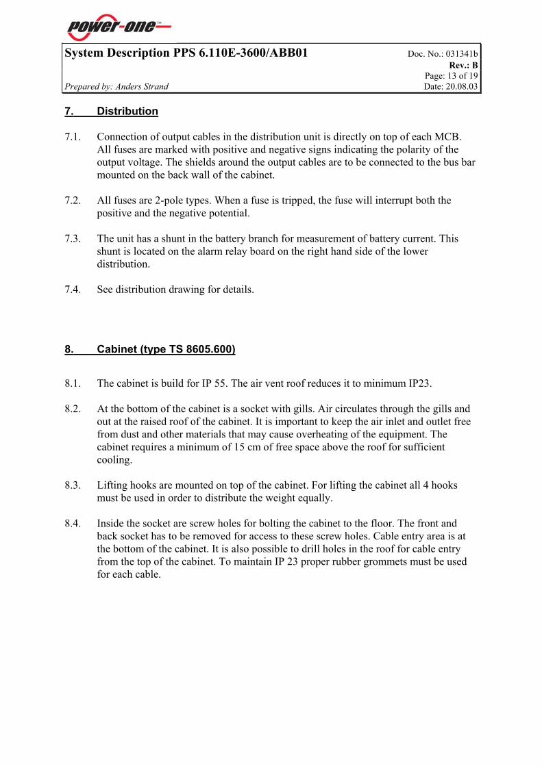
System Description PPS 6.110E-3600/ABB01 Doc. No.: 031341b Rev.: B Page: 13 of 19 Prepared by: Anders Strand Date: 20.08.03 7. Distribution 7.1. Connection of output cables in the distribution unit is directly on top of each MCB.
All fuses are marked with positive and negative signs indicating the polarity of the output voltage. The shields around the output cables are to be connected to the bus bar mounted on the back wall of the cabinet.
7.2. All fuses are 2-pole types. When a fuse is tripped, the fuse will interrupt both the
positive and the negative potential. 7.3. The unit has a shunt in the battery branch for measurement of battery current. This
shunt is located on the alarm relay board on the right hand side of the lower distribution.
7.4. See distribution drawing for details.
8. Cabinet (type TS 8605.600) 8.1. The cabinet is build for IP 55. The air vent roof reduces it to minimum IP23. 8.2. At the bottom of the cabinet is a socket with gills. Air circulates through the gills and
out at the raised roof of the cabinet. It is important to keep the air inlet and outlet free from dust and other materials that may cause overheating of the equipment. The cabinet requires a minimum of 15 cm of free space above the roof for sufficient cooling.
8.3. Lifting hooks are mounted on top of the cabinet. For lifting the cabinet all 4 hooks
must be used in order to distribute the weight equally. 8.4. Inside the socket are screw holes for bolting the cabinet to the floor. The front and
back socket has to be removed for access to these screw holes. Cable entry area is at the bottom of the cabinet. It is also possible to drill holes in the roof for cable entry from the top of the cabinet. To maintain IP 23 proper rubber grommets must be used for each cable.

System Description PPS 6.110E-3600/ABB01 Doc. No.: 031341b Rev.: B Page: 14 of 19 Prepared by: Anders Strand Date: 20.08.03 8.5. Cabinet dimensions (See type TS 8605.600)
Cabinet dimensions

System Description PPS 6.110E-3600/ABB01 Doc. No.: 031341b Rev.: B Page: 15 of 19 Prepared by: Anders Strand Date: 20.08.03
475
499
505
512
597
Plinth dimensions

System Description PPS 6.110E-3600/ABB01 Doc. No.: 031341b Rev.: B Page: 16 of 19 Prepared by: Anders Strand Date: 20.08.03 9. Batteries 9.1. The battery back up consists of 9 batteries connected in series. These batteries are
valve regulated (sealed) SBS 30 types from Hawker Batteries. Each battery weighs 9 Kg. Other batteries may be used.
9.2. Batteries that are mounted in a cabinet with electronic equipment have to be valve
regulated (gas free type). 9.3. From the manufactor it is recommended to charge these batteries at 2.28V per cell. With 9 batteries in series there are 54 cells that require 54x2.28V=123.1V float
charge. 9.4. In the distribution there is a LVD (Low Voltage Disconnection) contactor that protects
the batteries from deep discharging in the event of mains failure. The PCU 6.00E supervises the battery voltage and automatically turn off the batteries if their voltage is lower than 1.8V per cell. This means that the battery back up will be turned off when the voltage drops under: 54x1.8V=97.2V.
9.5. It is possible to turn off the battery back up manually with an ESD (Emergency Shut
Down) contactor. The ESD is operated with an external 24V signal and has a time delay of approximately 60 seconds. It is possible to adjust the time delay. See Installation Guide for details.

System Description PPS 6.110E-3600/ABB01 Doc. No.: 031341b Rev.: B Page: 17 of 19 Prepared by: Anders Strand Date: 20.08.03 10. Actions at alarm condition Below there are listed a number of alarm conditions and some recommended steps to
repair. Find the alarm condition and do the recommendations step by step. If you do not succeed with the first recommendation, try the next one. If you do not succeed at all, please take contact with our service department.
10.1. Low output voltage 10.1.1. Measure input mains. 10.1.2. Check total output current. It should not exceed maximum capacity. 10.1.3. Locate the faulty module and replace it.
10.2. High output voltage 10.2.1. Locate the faulty module and replace it. 10.2.2. Adjust module position to correct level.
10.3. Fuse alarm- (option) 10.3.1. Ensure that the load disconnecting contacts are activated. 10.3.2. Locate the faulty fuse (load or battery) and replace it.
10.4. Module alarm 10.4.1. Pull out the PMP 6.00 SIC, check the fuse mounted in the mains input plug. 10.4.2. If the fuse is blown replace it, otherwise replace the module.
10.5. Mains failure 10.5.1. Measure mains at the input terminals and at the module input contacts on the subrack.
10.6. Earth failure 10.6.1. Alarm limit for resistance to ground (chassis) can be adjusted within 0-1MΩ in the
control unit PCU 6.00E. 10.6.2. Earth failure can be simulated by connecting a resistance less than pre-set value
between “ + “ and chassis or “ – “ and chassis. Red LED (Earth failure) in PCU 6.00E illuminates. Voltage from “+” or “-“ to ground
and earth resistance are indicated in the displays. Earth fault to positive Voltage from chassis to 110V. Earth fault to negative Voltage from chassis to 0V.

System Description PPS 6.110E-3600/ABB01 Doc. No.: 031341b Rev.: B Page: 18 of 19 Prepared by: Anders Strand Date: 20.08.03 10.7. Symmetry failure- (option) 10.7.1. Verify that all cables are connected. 10.7.2. Measure the voltage of the battery blocks. If the voltage is too low, replace the battery
block or consider replacement of the whole battery bank.
10.8. Over voltage shut down in module 10.8.1. Locate the faulty module. 10.8.2. Pull out and plug in the module after the front LED goes out. 10.8.3. If the module goes in over voltage shut down mode again, the module is faulty and has
to be replaced.
10.9. Mall function on PCU 6.00E 10.9.1. Pull out the PCU 6.00E, and plug in the unit once more. 10.9.2. Pull out the PCU 6.00E; check the fuse mounted on PPR 6.00E/7 near the PCU 6.00E
position. 10.9.3. If the fuse is blown replace it, otherwise the PCU 6.00E is faulty and has to be
replaced.
11. Maintenance 11.1. The system does not require any special maintenance, except from normal cleaning
and verifying of correct operation. It is very important to keep air inlets and outlets free from dust or other materials, which may prevent free air circulation through the cubical.
11.2. Minimum once a year output voltage should be verified to be within limits. Result of
the test should be filed to see any deviations.

System Description PPS 6.110E-3600/ABB01 Doc. No.: 031341b Rev.: B Page: 19 of 19 Prepared by: Anders Strand Date: 20.08.03 12. Change of EPROM If a change of EPROM is desired or must be made, please proceed according to the following: 12.1. Use protection against static electricity. 12.2. Pull out the control unit, PCU 6.00E. 12.3. Remove the two screws on the lower side panel, which the circuit boards are NOT mounted. Pull out the side panel. 12.4. Remove the IC marked PCU 6.00E . . .. 12.5. Insert a new EPROM. NOTE! Make sure it is correctly inserted. 12.6. Reassemble the side panel and replug the control module.
Sideview of PCU 6.110E

Installation guide PPS 6.110E-3600/ABB01 Doc. No.: 031356b Rev.: B Page: 1 of 12 Prepared by: Anders Strand Date: 20.08.03
Approved by: Roar Fagerhus Date: 20.08.03 G:\CC\K-DOK\06\031356b.doc
INSTALLATION GUIDE POWER SUPPLY SYSTEM
PPS 6.110E-3600/ABB01 CONTENT: Page: 1. GENERAL................................................................................................................................................... 2
2. INSTALLATION........................................................................................................................................ 2 2.1. MOUNTING............................................................................................................................................ 2 2.2. CONNECTIONS ...................................................................................................................................... 4 2.3. RECOMMENDED CABLE AREA ............................................................................................................ 11
3. COMMISSIONING.................................................................................................................................. 12

Installation guide PPS 6.110E-3600/ABB01 Doc. No.: 031356b Rev.: B Page: 2 of 12 Prepared by: Anders Strand Date: 20.08.03
1. General 1.1. The PPS 6.110E-3600/ABB01 is a modular system, based on a 19" wide floor cabinet
and one subrack, PPR 6.00E/7. Each subrack can be equipped with 1-6 rectifiers PMP 6.00 SIC and one control unit PCU 6.00E. There are two battery shelves in the lower part of the cabinet.
1.2. The PPS 6.110E-3600/ABB01 is delivered with the customer specified configuration
and number of rectifiers. 1.3. The system is based on natural convection cooling. It is very important to install the
cabinet in a way, which does not prevent free air circulation through the cabinet. There must be a minimum of 15cm of free space above the cabinet for hot air to escape through the air vent roof.
2. Installation
2.1. Mounting After unpacking the system(s), do installation according to the following steps: 2.1.1. Ensure that the system has not been damaged during transport. 2.1.2. Place the cabinet in its intended position. Use the delivered lifting hooks mounted on
top of the cabinet to lift it. These lifting hooks are screwed into the frame of the cabinet. The cabinet must never be lifted with the batteries installed.
2.1.4 When mounting the cabinet to the floor it is useful to remove the front panel of the
plinth for easier access to the holes inside the plinth. See the drawing of the cabinet footprint.

Installation guide PPS 6.110E-3600/ABB01 Doc. No.: 031356b Rev.: B Page: 3 of 12 Prepared by: Anders Strand Date: 20.08.03
Front
567,5mm537,5mm507,5mm
600mm
32,5mm62,5mm92,5mm
17,5mm47,5mm
452m
m
422,
5mm
469m
m
Holes for mounting the cabinet to the floor
Holes for mounting the cabinet to the floor
2.1.3. Fix the cabinet to the wall with the wall brackets on top of the cabinet. Use a distance
bar if the wall is too far back. 2.1.4. Dismantle the cabinet's dummy panels for the distribution modules. 2.1.5. If PMP 6.00 SIC modules are installed, unscrew the fixing screws and pull out the
modules. 2.1.6. Switch off all output breakers and the battery breaker.
Installation guide PPS 6.110E-3600/ABB01 Doc. No.: 031356b Rev.: B Page: 4 of 12 Prepared by: Anders Strand Date: 20.08.03
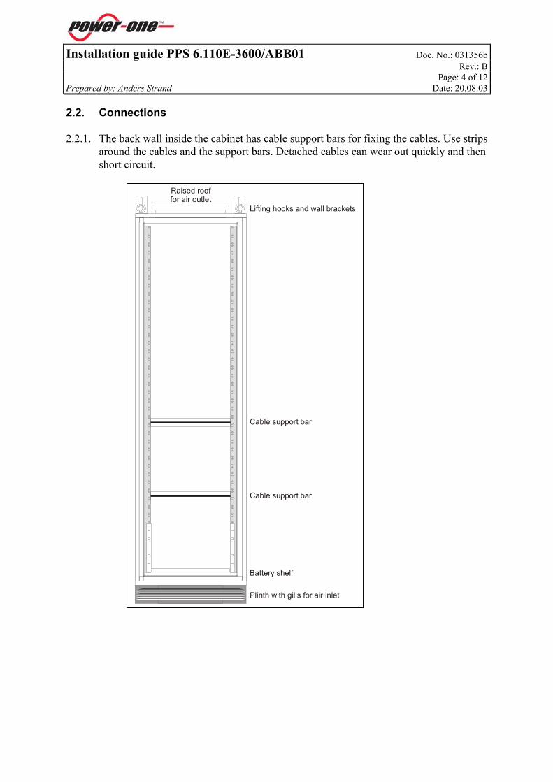
2.2. Connections 2.2.1. The back wall inside the cabinet has cable support bars for fixing the cables. Use strips
around the cables and the support bars. Detached cables can wear out quickly and then short circuit.
Battery shelf
Cable support bar
Cable support bar
Lifting hooks and wall brackets
Plinth with gills for air inlet
Raised rooffor air outlet

Installation guide PPS 6.110E-3600/ABB01 Doc. No.: 031356b Rev.: B Page: 5 of 12 Prepared by: Anders Strand Date: 20.08.03
2.2.2. For cable entry at the bottom of the cabinet the cables must go under the plinth either through the floor or between the base plates.
2.2.3. The cabinet can not be delivered with pre made holes for cable to/from the system at
the top. In order to maintain the high IP grade the holes and grommets for all cables must be made specific for each cable depending on its diameter. There must be no holes left open.
Cabinet front(grey color)
Right side of the cabinet (white color)
Bolts fixingthe cabinet
Cabinet back
Cable entry
Cable support bars insidethe cabinet
Front/sideview of the cabinet
Base plate or floor

Installation guide PPS 6.110E-3600/ABB01 Doc. No.: 031356b Rev.: B Page: 6 of 12 Prepared by: Anders Strand Date: 20.08.03
2.2.4. The connection unit at the top of the cabinet includes the mains input, ESD function, alarm relay, and interconnection. 2.2.5. Connect mains input first. Make sure the mains is turned off. 2.2.6. Mains input is located in the upper right corner of the cabinet. Check that the mains
input terminal blocks are connected with fishplates according to one of the 3 possible mains input. See the “Connection Unit PPS 6.110E-3600” sheet.
2.2.7. Recommended mains fuse: 3x10A Fuse for 400V AC 3-phase (L1, L2, L3) 2x16A Fuse for 230V AC single phase (L, N) 3x10A Fuse for 230V AC 3-phase Insulated Terra (L1, L2, L3) 2.2.8. WARNING! The system must be connected to ground or dangerous and
hazardous voltages may occur.
1
PE PE PE
1 12 2 23
N N L1
3 34 4 45
L1 L2
5 56
L2 L
6 67
L3 L3
7 7
3x400V AC: 1x230V AC: 3x230V AC:
Connection UnitESD Alarm Interconnection Mains input

Installation guide PPS 6.110E-3600/ABB01 Doc. No.: 031356b Rev.: B Page: 7 of 12 Prepared by: Anders Strand Date: 20.08.03
2.2.9. The ESD function is an option for the system. It is located in the connection unit in the upper left side of the cabinet. This function is always by-passed with a cable from factory. In order to activate the ESD function this cable going from pin 11 to pin14 on the relay socket must be removed. See the “Connection Unit PPS 6.110E-3600” sheet for information. The terminal blocks marked 8, 9 and 10 are for controlling the ESD function. For disconnecting the ESD connector apply a 24V signal at the terminal block no. 9 (ground at no. 8). The ESD contactor will then open in approximately 1 min. Engage the ESD connector with a 24V signal at terminal block no. 10. There will be no delay for the ESD connector closing.
2.2.10. The time delay for the ESD function can be adjusted. A time module is located in the
socket under the ESD relay. The delay time equals the time set by the triggers multiplied by the factor set on the adjustment wheel. From factory the time delay has been set to approximately 1 min.
Function Time
Adjustment wheel
Triggers
The time-delay is set by the positionof the triggers(as shown below) and the adjustment wheel.
.
.
1s
10d1d10h1h10m.
1m10s
ESD
in
Gnd
ESD
out
F ESD+ -
8 9 10
ESD
Time delay moduleRemove this cable to activatethe ESD function

Installation guide PPS 6.110E-3600/ABB01 Doc. No.: 031356b Rev.: B Page: 8 of 12 Prepared by: Anders Strand Date: 20.08.03
2.2.11. The alarm contact is a potential free switch over contact for remote supervision of the system. There are 3 terminal blocks in the connection unit for this alarm. The terminal block marked no. 11 and 13 are normal closed and no. 11 and 12 are normal open. See the “Configuration PCU 6.110E” sheet for the alarm conditions.
2.2.12. The interconnection is for paralleling 2 systems. This only to be done during service
e.g. changing batteries in a system. The interconnection will influence on the earth failure detection and must therefore not be permanently connected.
NO
C NC
11 12 13
Alarm
14 15
Interconnection
+ -System A System B

Installation guide PPS 6.110E-3600/ABB01 Doc. No.: 031356b Rev.: B Page: 9 of 12 Prepared by: Anders Strand Date: 20.08.03
2.2.13. The system has a satellite alarm/interface board for connection of temperature probe, symmetry measurement and a RS232/485 plug for communication with a PC.
This board is located to the right in the lower distribution. For temperature compensated charging of the battery bank it is possible to connect a
temperature probe. The PCU regulates the float charge according to the ambient temperature.
The symmetry measurement of up to 2 battery banks can also be supervised. For communication between the PCU 6.00 and a PC it is necessary to use the
PowCom program. All settings in the “Configuration PCU 6.110E” sheet can be altered with this program.
Alarm relay board in distribution 1Alarm relay board BM0369 with 4 alarm relays,symmetry measurement, temperature probeand RS 232 communication port
RS232/ 485 comm. por t
TB1
TB3TB2
1
4
7
10
13
T 1 Alarm 1B
TB1 Alarm 2 (Not in use)
T 1 Alarm 3 (Not in use)B
Not in use (For LVD contactor)
T 1 Alarm 4 (Not in use)B
2
5
8
11
14
3
6
9
12
15
1
16
SHUNT
Green, T
Red, +
Blue, -
TTemp. probe
Red
Red
Green
Green
Blue
BluePTC
1
2
3
4
5
64
3
2
1Battery bank 1:
nine 12V batteriesconnected in series
108V
72V
36V
Battery bank 2 to beconnected the same
way as for battery bank 1
108V
0V
PTC

Installation guide PPS 6.110E-3600/ABB01 Doc. No.: 031356b Rev.: B Page: 10 of 12 Prepared by: Anders Strand Date: 20.08.03
2.2.14. The system is delivered with 2 or 3 battery shelves for battery back up during mains failure. The battery bank is made up of 9 12V batteries connected in series. Make sure that the battery fuse is switched off before connecting the batteries. See the “Battery Installation PPS 6.110E-3600” sheet for information.
2.2.15. The batteries must have 3 layers of double-sided tape on their underside. Take off the
tape protection. Carefully put the batteries on the battery shelves in the cabinet as shown on the drawing beneith. Make sure that the batteries are placed correctly, because the tape can be damaged if the batteries have to be moved later.
2.2.16. Fix all batteries with strips through the holes in the battery shelves. Interconnect the
batteries with the supplied copper links. Connect the cable from the upper battery bank to the lower battery bank. All 9 batteries should now be connected in series.
2.2.17. Connect the battery bank to the battery fuse. Check that the polarity on the underside
of the battery fuse is correct. 2.2.18. Fasten the battery temperature probe in the middle of the battery bank in the upper
battery shelf. 2.2.19. NOTE! The strips that are used to fix the batteries to the battery shelves can be
opened with a little screwdriver by pushing the lock-spring a little bit backwards. If it is necessary to exchange a battery these strips can be re-used to fix the new battery.
To -battery fuse
To +battery fuse
Battery temperatureprobe
Battery shelf 1
Battery shelf 2
Top view of batteries

Installation guide PPS 6.110E-3600/ABB01 Doc. No.: 031356b Rev.: B Page: 11 of 12 Prepared by: Anders Strand Date: 20.08.03
2.2.20. Connect the load cables directly on top of their respective fuses. All fuses are marked with “+” and “-“ for polarity indication. Screened load cables must be connected to the earth-connected (chassis) bus bar behind the distribution fuses. This will assure proper grounding of the load cables. See the “Distribution PDU 6.110E” sheet for information.
2.3. Recommended cable area 2.3.1. All internal cables are sized for max. performance of the system, i.e. 6 modules in the
subrack. It is recommended for the customer to use the same cable sizes. Cable sizes for the system is:
Mains : 2.5 mm2 Battery : 16 mm2
Interconnection : 16 mm2
Load fuses : 2,5 mm2 ESD : 1.5 mm2
Alarm at TB1 : 1.5 mm2
+ -+ -+ - + - + - + - + - + - + - + -
F4F3F2 F5 F6 F7 F8F1
ABBC10
ABBC10
ABBC10
ABBC10
ABBC10
ABBC10
ABBC10
ABBC10
ABBD50
ABBD50
FB1 FINT
Earth connected bus bar for screened load cables

Installation guide PPS 6.110E-3600/ABB01 Doc. No.: 031356b Rev.: B Page: 12 of 12 Prepared by: Anders Strand Date: 20.08.03
3. Commissioning 3.1. Technical staff with necessary experience and knowledge regarding power supplies
systems and batteries must accomplish the commissioning. 3.2. Before the modules are put back in the subrack turn on the mains power. Measure the
voltage at the mains input terminal blocks and in all 6 positions on the subrack. Check that all screws are properly tightened and all soldering is intact. If the mains voltage is correct turn off the mains. Put the modules in the subrack.
3.3. Turn on the mains and check that the modules are operating correctly. The PCU
6.00E will initialise the system and operate normally after approximately 1 minute. All red LED’s on the PCU 6.00E shall go out. Only the green LED will illuminate if the system is operating correctly.
3.4. Step through the PCU 6.00E menu and check that all parameters are correctly set. See
“System Description PPS 6.110E-3600” for details. 3.5. Measure the output voltage at the underside of the output fuses. Check that the
polarity is correct. Turn on the output fuses. 3.6. Measure the battery bank voltage and check the polarity at the underside of the battery
fuse. Turn on the battery fuse. 3.7. The system should now operate correctly.
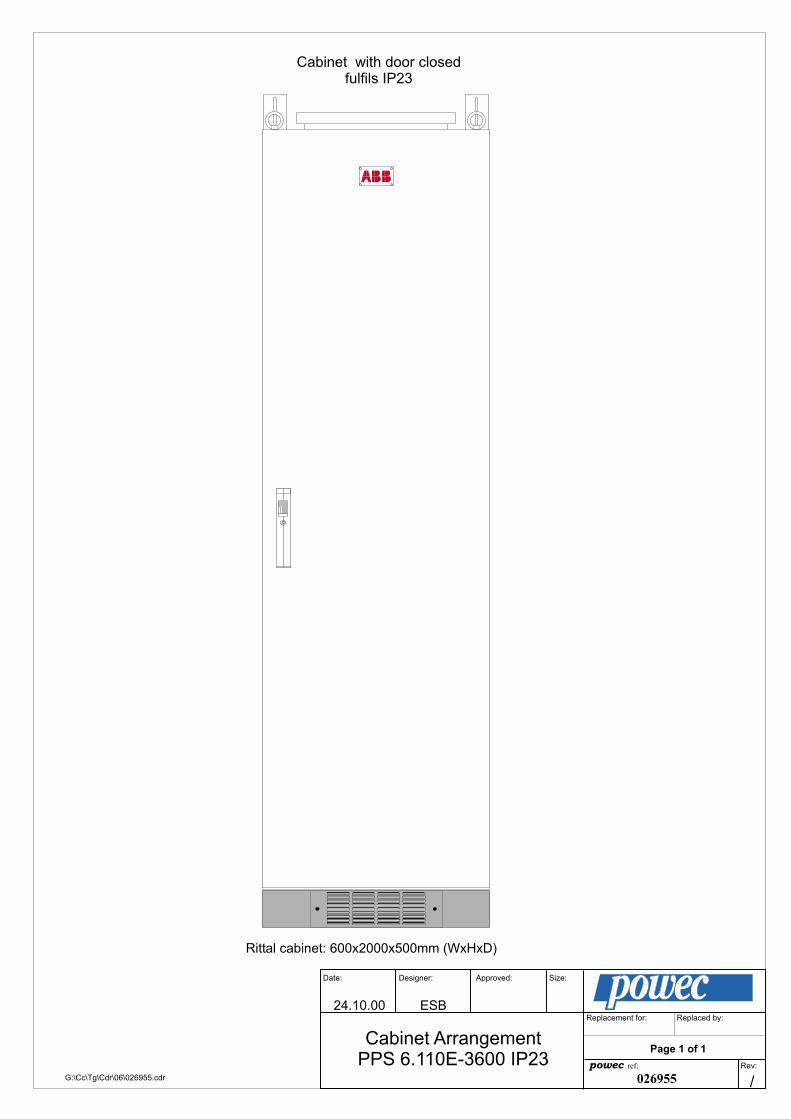
24.10.00 ESB
Size:Date:
Replacement for: Replaced by:
Designer: Approved:
Rev:
Cabinet ArrangementPPS 6.110E-3600 IP23 powec ref:
/026955
Page 1 of 1
Cabinet with door closedfulfils IP23
Rittal cabinet: 600x2000x500mm (WxHxD)
G:\Cc\Tg\Cdr\06\026955.cdr
RITTAL

24.10.00 ESB
Size:Date:
Replacement for: Replaced by:
Designer: Approved:
Rev:
Cabinet LayoutPPS 6.110E-3600/ABB01 powec ref:
/026956
Page 1 of 1
G:\Cc\Tg\Cdr\06\026956.cdr
Battery shelf
Air vent roof with lifting hooksand wall brackets
Connection Unit
Distribution 2
Distribution 1 withalarm relay board BM0369
Subrack PPR 6.110E-3600 with1xPCU 6 and max. 6xPMP 6
Battery shelf
Plinth
F1
PL31 PL41 PL51 PL61PL21PL11PL01
PL10PL9
powecpowec
PCU 6.110
BATTERY TEST
TOTAL
TEMP. ALARM
BATTERY
EARTH FAILURE
MODULE 1
MODULE 2MODULE 3
MODULE 4MODULE 5
MODULE 6
OPERATION
LOW VOLT. ALARMHI. VOLT. ALARM
MODULE ALARMLOW VOLT. DISC.
FUSE FAILUREMAINS FAILURE
BOOST
VOLTAGE
CURRENT
SELECT
POWER ON
O.V. SHUT-DOWN
ALARM
powecpowec
PMP 6.110 SIC
POWER ON
O.V. SHUT-DOWN
ALARM
powec
PMP 6.110 SIC
POWER ON
O.V. SHUT-DOWN
ALARM
powecpowec
PMP 6.110 SIC
ABBC10
ABBC10
ABBC10
ABBC10
ABBC10
ABBC10
ABBC10
ABBC10
ABBK50
ABBK50
ABBC10
ABBC10
ABBC10
ABBC10
ABBC10
ABBC10
ABBC10
ABBC10
ABBC10
ABBC10
ABBC10
ABBC10
ABB
C02
SCHRACK
SCHRACK
34
A2
32
31
24
21
12
11
14
A1
12
12
22
22
14
14
NC
NC

26.10.00 ESB
Scale:Date:
Replacement for: Replaced by:
Designer: Approved:
Rev:
Cabinet InstallationPPS 6.110E-3600/ABB01 powec ref:
/
Page 1 of 1
Cabinet Installation:
1. Use strops through the lifting hooks at the top of the cabinet to liftit in its intended position.
2. Demount the air inlet panels for easy access to the inside of the plinth
3. Fix the cabinet to the floor or base plate with 4 bolts through the holesinside the plinth
4. Mount the air inlet panels
Lift the cabinet with strops throughthe lifting hooks
Use 4 blots to fixthe cabinet to the floor
Demount the air inletpanels and mountagain after the cabinethas been bolted to thefloor/base plate.
Liftinghooks
026957G:\Cc\Tg\Cdr\06\026957.cdr
Fix the cabinet to the wallwith 2 bolts through thewall brackets

08.06.01 ANS
Scale:Date:
Replacement for: Replaced by:
Designer: Approved:
Rev:
Battery InstallationPPS 6.110E-3600/ABB01 powec ref:
A
Page 1 of 1
Battery Installation:
1.
5.
2.
3.
4.
Turn off the battery fuse!Take out the batteries and put 3 layers oftape (200 mm long) on their underside.
Connect the battery bank to the battery fuse.Meassure the voltage over the battery bankwith a DMM and check that the polarity and voltageis correct before turning on the battery fuse.
Put on a thin film of grease on the battery poles and on the copperinterlinks. Connect the 9 batteries in series with theinterlinks and the cable for interlinking the upperand lower battery group(see installation guide).
Fasten the batteries with strips through the holes inthe battery shelves. Use 2 strips for each battery.It is possible to open a strip by pushing itslock-spring backwards with a little screwdriver.
Place the batteries carefully on the battery shelves.It is difficult to move the batteries with the tape onthe underside so make sure they are placed correctly.
Strips for holding the battery
Holes in the battery shelf
Use 3 layers of double sided tapeon the underside of the batteries
026958G:\Cc\Tg\Cdr\06\026958.cdr

G:\Cc\K-dok\06\027081.cdr

Approved:Date: Designer: Scale:
ref: Rev:
Replaced by:Replacement. for:
Control:
19.03.03 ANS 1:10
026905
Page 01 of 01Connection unit
PPS 6.110E-3600/ABBAG:\cc\tg\cdr\06\026905a.cdr
Mains input
1 2 3 4 5 6 7
ES
Din
NO
Gnd
CES
Dout
NC
F ESD+ -
8 9 10 11 1412 1513
Alarm InterconnectionESD
ABB
C02
+ -
SCHRACK
SCHRACK
34
A2
32
31
24
21
12
11
14
A1
12
12
22
22
14
14
NC
NC
Mains inputESD operation
With the delivered fish plates it is possibleto change between these 3 different mains inputs:
1
PE PE PE
1 12 2 23
N N L1
3 34 4 45
L1 L2
5 56
L2 L
6 67
L3 L3
7 7
3x400V AC: 1x230V AC: 3x230V AC:All systems are delivered without the ESD function.In order to activate this function remove thepink cable from pin 11 to 14.
Time and function
,8 ,9
Function
Function
Time
Time
Adjustment wheel
Time and function is set as shownbelow.
The adjustment wheel is set to 1.
Triggers

1 2 3 4 5 6 7
G:\Cc\Tg\Vsd\06\026980.vsd
Approved:
06.11.00Date: Designer:
ESB
Page 1 of 1
Scale:
026980p o w e c ref: Rev:
/
Schematic DiagramPPS 6.110E-3600/ABB01
Replaced by:Replacement for:
BM0369RS1Shunt
+
-
TB2 Temp.134
2
4Sym.1
TB3Sym.2 5
6
1
326
PL9
Pr. alarm 1 123
Pr. alarm 2
Pr. alarm 3
Load disc. 2
Pr. alarm 4
12345
TB5Ext.Transfoshunt
12 PL1
1234567
TB4Load inLoad out
TB1
9
RS232
10
PL10
12 TB10
456
789
101112
131415
26 pin ribbon cable
- Battery
Mains inputterminal blocks
+ Battery
PPR 6.110E
PCU6.110E
+
-
BM0357
PL10
PL9
L1N1PE
L2N2PE
L3N3PE
L4N4PE
PEN5L5
PEN6L6
26
10
10 pin ribbon cable
+ Interconnection: 14
- Interconnection: 15
- Load 1
+ Load 1
- Load 2
+ Load 2F2
Distribution
Subrack
- Load n
+ Load nFn
F1
FINT
LVD
A1 A2
E2 E1
ESD in: 10
ESD out: 9
FB1
A1 A2
24V
24V
∆tA1 A2
FESD
ESD
C: 11NC: 12NO: 13 Alarm 1
14 11
ESD BY-PASS
0V: 8
Grey
Black
2/4
6/8
1/3
5/7
2/4
6/8
1/3
5/7
161 162
21
24

G:\Cc\Tg\Vsd\06\024918.vsd
Approved:
22.02.00Date: Designer:
ESB
Page 1 of 1
Scale:
024918p o w e c ref: Rev:
/
Connection of Temperature Probeand Symmertry measurement for
PPS 6.110E
Replaced by:Replacement for:
BM0369/1RS1
Shunt
+
-
TB2 Temp.1
3
4
2
4
Sym.1TB3
Sym.2 5
6
1
326
PL9
Pr. alarm 1 1
2
3
Pr. alarm 2 4
5
6
Pr. alarm 3 7
8
9
Load disc. 2 10
11
12
Pr. alarm 4 13
14
15
1
2
3
4
5
TB5Ext.Transfoshunt
1
2 PL1
1
2
3
4
5
6
7
TB4Load inLoad out
TB1
9RS232
PL1010
1
2 TB10BoostMains
RedGreenWhite
0V DC
108V DC
Battery string 1consisting of 9
12V battery blocksconnected in series
Alarm relay boardBM0369/1
36V
T
PTC
PTC
PTC
Temperature probe tobe glued to a battery in
the middle of thetopmost battery shelf
72V
TB1/1Alarmrelays TB3/1
Symmetrymeasurement
TB2/1Temperature
probe
SHUNT
1234
123456
16151413121110987654321
GreenRedBlue
RS232comm.
port
RedGreenWhite
Symmetry measurement forbattery string 2 to be
connected the same wayas for battery string 1

powec asConfiguration PCU 6.110E Doc. No.: 027080.doc
Rev.: /Page 1 of 2
Prepared: Erlend Breivik Date: 22.11.00
Approved: Roar Fagerhus Date: 22.11.00G:\CC\PCU\06\027080.doc
Output voltage Default settings Factory settings
Default value (potentiometers in the subrack) 120,4V - *
U1 Normal 123,1V
U2 Boost 123,1V
U3 Test 104,0V
U4 Spare 123,1V*Default value is not to be readjusted.
Alarms/functions PCU 6.110E, software no.: PCU 6.110E T: A11 version 1.01
Condition: Pre-set thresholds: Timelag
Operation of alarm contacts at TB1(1=activated)
Default settings Factorysettings
Pin 1-3 Pin 4-6 Pin 7-9 Pin 13-15
AL.1 AL.2 AL.3 AL.4Earth failure <100kΩ to ground 30S 1Low volt alarm 106,0V 2 S 1High volt alarm 129,0V 2 S 1Module alarm Malfunction on
module2 S 1
Battery/distributionfuse alarm
NA 2 S
Mains failure <165V AC 2 S 1High temp. alarm 40ºC 2 S 1Increase capacity 100% 2 S 1Battery failure Battery failed
during test2 S 1
Symmetry failure NA 2 SBattery disconnection 97,2V 1Battery reconnection 115,0VBattery test
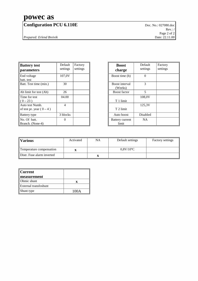
powec asConfiguration PCU 6.110E Doc. No.: 027080.doc
Rev.: /Page 2 of 2
Prepared: Erlend Breivik Date: 22.11.00
Battery testparameters
Defaultsettings
Factorysettings
Boostcharge
Defaultsettings
Factorysettings
End voltagebatt. test
107,0V Boost time (h) 0
Batt. Test time (min.) 30 Boost interval(Weeks)
3
Ah limit for test (Ah) 26 Boost factor 5Time for test( 0 – 23 )
04.00T 1 limit
108,0V
Auto test Numb.of test pr. year ( 0 – 4 )
4T 2 limit
125,3V
Battery type 3 blocks Auto boost DisabledNo. Of batt.Branch. (None-4)
0 Battery currentlimit
NA
Various Activated NA Default settings Factory settings
Temperature compensation x 0,8V/10ºC
Distr. Fuse alarm inverted x
CurrentmeasurementOhmic shunt xExternal transfoshuntShunt type 100A

powec asDistribution PDU 6.110E Doc. No.: 025353
Rev.: /Page 1 of 3
Prepared: Erlend Breivik Date: 28.03.00
\\POW1\VOL4\CC\PDU\06\025353.doc
Distribution 1
Fuse 4A 6A 10A 16A 32A 50A Char. Type of equipmentFB1 x K (2-pole) BatteryFINT x K (2-pole) Interconnection
F1 x C (2-pole)F2 x C (2-pole)F3 x C (2-pole)F4 x C (2-pole)F5 x C (2-pole)F6 x C (2-pole)F7 x C (2-pole)F8 x C (2-pole)
+ -+ -+ - + - + - + - + - + - + - + -
F4F3F2 F5 F6 F7 F8F1
ABB
C10
ABB
C10
ABB
C10
ABB
C10
ABB
C10
ABB
C10
ABB
C10
ABB
C10
ABB
D50
ABB
D50
LOAD
FB1 FINT

powec asDistribution PDU 6.110E Doc. No.: 025353
Rev.: /Page 2 of 3
Prepared: Erlend Breivik Date: 28.03.00
Distribution 2
Fuse 4A 6A 10A 16A 32A 50A Char. Type of equipmentF9 x C (2-pole)
F10 x C (2-pole)F11 x C (2-pole)F12 x C (2-pole)F13 x C (2-pole)F14 x C (2-pole)F15 x C (2-pole)F16 x C (2-pole)F17 x C (2-pole)F18 x C (2-pole)F19 x C (2-pole)F 20 x C (2-pole)
+ -+ -+ - + - + - + - + - + - + - + - + - + -
F11F10 F13F12 F14 F15 F16 F17 F18 F19 F20F9
ABB
C10
ABB
C10
ABB
C10
ABB
C10
ABB
C10
ABB
C10
ABB
C10
ABB
C10
ABB
C10
ABB
C10
ABB
C10
ABB
C10
LOAD

powec asDistribution PDU 6.110E Doc. No.: 025353
Rev.: /Page 3 of 3
Prepared: Erlend Breivik Date: 28.03.00
Recommended fuses: Type of equipment:Mains fuse in each module (5x20mm) T4A Power module PMP 6.110 SICF1 (5x20mm) F2A Control module PCU 6.110E
Fuse forPMP 6.110 SIC
PMP 6.110 SICseen from the back
Fuse for PCU 6.110E
Subrack PPR 6.110E
F1
PL 31 PL 41 PL 51 PL 61PL 21PL 11PL 01