2d gain enhancement based on single-layer siw...
TRANSCRIPT
Research Article2D Gain Enhancement Based on Single-Layer SIW CorrugatedTechnique with Slot Array Feeder
Mingtuan Lin and Chenglong Lin
College of Electronic Science and Engineering, National University of Defense Technology, Changsha 410073, China
Correspondence should be addressed to Mingtuan Lin; [email protected]
Received 14 November 2017; Accepted 21 January 2018; Published 25 March 2018
Academic Editor: Chien-Jen Wang
Copyright © 2018 Mingtuan Lin and Chenglong Lin. This is an open access article distributed under the Creative CommonsAttribution License, which permits unrestricted use, distribution, and reproduction in any medium, provided the original workis properly cited.
Novel slot-array-based SIW corrugated technique is demonstrated to achieve 2D gain enhancement, namely, sharpening thebeamwidths in both E-plane and H-plane. Compared to other metallic corrugated methods to realize 2D gain enhancement, theproposed design, with SIW grooves to reduce the beamwidth in E-plane and slot array to increase the directivity in H-plane, hasa lower profile, weight, and design complexity, which can be easily fabricated with the common printed circuit board (PCB)technique. A prototype is designed and fabricated, with measurement presenting a low reflection coefficient less than −10 dBfrom 26.4GHz to 28.2GHz and an enhanced gain up to 18 dB. Overall, our proposed technique will be beneficial for the designof high-gain antenna in 5G wireless terminals.
1. Introduction
Ka-band has been announced to be part of the future 5Gspectrum plan [1]. In comparison with other frequency can-didates such as the E-, W-, and V-bands, the relatively lowKa-band poses less challenge for the 5G communicationdevices. Consequently, the researches of Ka-band antenna[2, 3] will be of significance for the future 5G technique.
To conquer the high loss of transmission, high-gainantenna is in demand for 5G techniques. Metallic corrugatedtechnique is one main method to enhance the gain ofantenna, which has been widely investigated [4–6]. A metal-lic corrugated design with rectangular waveguide feeder wasreported in [7], which consists of a surface slit surroundedby periodic straight grooves. The radiated wave from the slitcan be enhanced by the periodic grooves, which create in-phase superposition of the wave and improve the gain inthe normal direction. Such metallic corrugated antenna hasa 1D enhancement performance, that is, having a narrowbeamwidth in E-plane but a wide beam pattern in H-plane.Slit array was introduced in [8] to reduce beamwidth in H-plane, with slits fed by a rectangular waveguide. Obviously,the slit array requires multiple rectangular waveguides, which
increases the total weight and profile, and cannot be used incompact space of wireless terminals. Another method toachieve 2D gain enhancement [9] employed a dual metalliccorrugated plate, with three radiation slots on the top layer.However, the metallic technique makes the antenna heavyand cannot be used in the wireless terminals such as mobilephone. With the implementation of SIW techniques, three-layer PCBs were utilized in [10] as a replacement of metallicmaterial to realize high-gain antenna, whereas it only showsthat the radiation enhancement of E-plane and the multiplelayer technique also increases the design complexity andposes uncertain impacts during the fabrication and theinstallation. In our recent work [11], we proposed a novelsingle-layer SIW corrugated technique to achieve compara-ble gain enhancement as the metallic corrugated technique,based on which two low mutual coupling and high-gainmultiple input and multiple out (MIMO) antennas weredesigned [12]. The proposed single-layer SIW corrugatedtechnique is easy for fabrication and is more suitable forwireless terminal antennas.
The novelty of this paper is the slot-array-based SIWcorrugated technique to achieve 2D radiation enhancement,that is, increasing the directivity of both E-plane and H-
HindawiInternational Journal of Antennas and PropagationVolume 2018, Article ID 3684197, 6 pageshttps://doi.org/10.1155/2018/3684197

plane, which can further increase the gain. To the best of ourknowledge, our design is the first one antenna among thecorrugated methods to achieve 2D radiation enhancementwith only a single-layer PCB, which is of significance forthe high-gain antenna in 5G wireless terminals.
2. Antenna Structure
The layout of proposed antenna, with a dimension85.5mm× 36mm, is shown in Figure 1, which is comprisedof two main parts, namely, a SIW slot array feeder (threeslots) and four couples of periodic SIW grooves. The dimen-sions of SIW groove is 30mm× 0.3mm. To feed the SIW slotarray, a tapered microstrip line transition at the bottom is uti-lized, which is followed by a 2.92mm end launch connector.The central frequency of the design is 27.6GHz. For parallelgrooves, aligned slots can achieve better radiation enhance-ment than slots on two sides of central line of waveguide.Therefore, three slots are aligned in only one side of centralline, with a wavelength distance between each other. Havinglow loss in mm-band, Rogers 5880, with dielectric constant2.2, is chosen as the substrate. To better satisfy the commoncriteria used in corrugated technique, that is, h/λ = 0 25,where h is the thickness and λ is the wavelength, our designuses 1.575mm thickness level substrate. The diameter ofSIW vias is 0.4mm, and the distance of every two vias is0.6mm. The structure parameters of SIW slot array, SIWgrooves, and transition are optimized as shown in Figure 1to have a good impedance matching while keeping high-gain performance.
The mechanism of gain enhancement of the proposedantenna is as follows. The SIW grooves are to enhance thegain in E-plane, while the slot array increases the directivity
in H-plane. Specifically, the radiated wave from the SIWslot array travels along −y and +y directions, which createsin-phase electric field inside the grooves. Because of the in-phase superposition of the electric field, the radiation patterncan be enhanced.
3. Performance Analyses
Before the introduction of the simulation results of slot-array-based SIW corrugated antenna with four couples ofgrooves, the influence of the groove number on the SIW cor-rugated antenna is investigated first, which is shown inFigure 2. Please note that the groove number in the figure
Top view
Bottom view
SIW grooves
SIW slot array
85.5
36
4.3
0.9
10.5
9.5
0.3
3
1.15
6
Screw hole
Taperedtransition
y
x
0.5
Figure 1: The layout of the proposed antenna. All the dimensions are in mm.
6055504540353025201510
50
0 1 2 3 4 5 6 7Number of grooves
201918171615141312111098
Sim
ulat
ed g
ain
(dB)
3-dB
bea
m w
idth
(deg
ree)
E-plane (slot array)H-plane (slot array)
H-plane (single slot)Simulated gain (slot array)
Figure 2: 3 dB beamwidth and gain for different groove numbers ineach side.
2 International Journal of Antennas and Propagation

refers to the number in each side rather than two sides. It canbe seen that the simulated gain increases with the number ofgrooves for slot-array-based SIW corrugated antenna, while3 dB beamwidth in E-plane shows a contrast trend, havinga narrow beamwidth for large number of grooves. Also, itcan be found that the gain does not increase significantlywhen the number of grooves is larger than 4 and the beam-width does not decrease a lot as well. The more number ofgrooves, the larger size the antenna has. To trade off the sizeand the enhanced gain, 4 grooves in each side of the SIW cor-rugated antenna are chosen in our design. The 3 dB beam-width in H-plane is also shown in Figure 2, from which anarrow beamwidth (around 19°) of slot-array-based SIWcorrugated antenna can be observed compared to a wide
beamwidth (around 51°) of the SIW corrugated antennawith a single slot. This is consistent with the normalizedradiation pattern of H-plane in Figure 3(a). Obviously, theimplementation of the slot array in SIW corrugated antennasharpens the beamwidth in H-plane. Comparisons of radia-tion pattern between the slot-array-based SIW corrugatedantenna and slot array antenna on a flat surface are shownin Figure 3(b), from which a narrow beamwidth of E-planecan be achieved. It is noted that more ripples in E-planeoccur than in H-plane. That is because the phase responsesof SIW grooves are only quasi-in-phase; therefore, ripplesappear in other directions. While for slot array, it is easy toensure exact in-phase responses for three slots; thus, theripples of H-plane are relatively pure. Benefiting fromthe in-phase superposition of SIW corrugations and the slotarray, our proposed slot-array-based SIW corrugatedantenna can realize 2D gain enhancement. The field distribu-tions of top view and its cross-sectional view along line AA1in Figure 4 show that in-phase field inside the groove isexcited by the in-phase slot array. The in-phase superposi-tion of grooves and slot array enhances the gain in bothE-plane and H-plane.
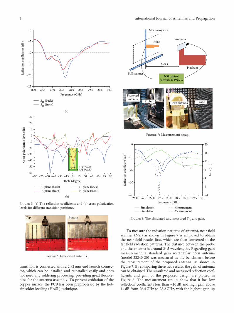
A tapered transition on the top would increase the crosspolarization. Therefore, the transition is located at the bot-tom. Comparison of S-parameter and cross polarizationperformance with transition at the back and front is shownin Figure 5. It can be seen from Figure 5(a) that the transitionlocation does not affect reflection coefficient a lot, while thecross polarizations within the half power beamwidth(HPBW) in E-plane and H-plane are suppressed when backtransition is employed, exhibiting a good linear polarizationas shown in Figure 5(b).
4. Measurement Results
The fabricated antenna is shown in Figure 6, which iscompact enough to be installed in mobile phone. The
H-plane (slot array)H-plane (Single slot)
030
60
90
120
150180
210
240
270
300
330
0−10
−20−30
−40
(a)
E-plane (four grooves)E-plane (no grooves)
030
60
90
120
150180
210
240
270
300
330
0−10
−20−30
−40
(b)
Figure 3: Radiation pattern comparisons between (a) the slot-array-based and single-slot-based SIW corrugated antennas and(b) slot-array-based SIW corrugated antenna and slot arrayantenna on a flat surface.
x
y
A A
A A
y
z 140137133130126123119116112109105
141138134130127123119116112108105
dB (1 mV/m)
dB (1 mV/m)
Figure 4: Field distributions from top view and its cross-sectionalview along line AA1.
3International Journal of Antennas and Propagation
transition is connected with a 2.92mm end launch connec-tor, which can be installed and reinstalled easily and doesnot need any soldering processing, providing great flexible-ness for the antenna assembly. To prevent oxidation of thecopper surface, the PCB has been preprocessed by the hot-air solder leveling (HASL) technique.
To measure the radiation patterns of antenna, near fieldscanner (NSI) as shown in Figure 7 is employed to obtainthe near field results first, which are then converted to thefar field radiation patterns. The distance between the probeand the antenna is around 3~5 wavelengths. Regarding gainmeasurement, a standard gain rectangular horn antenna(model 22240-20) was measured as the benchmark beforethe measurement of the proposed antenna, as shown inFigure 7. By comparing these two results, the gain of antennacan be obtained. The simulated andmeasured reflection coef-ficients and gain of the proposed design are plotted inFigure 8. The measurement results show that it has lowreflection coefficients less than −10 dB and high gain above14 dB from 26.4GHz to 28.2GHz, with the highest gain up
0
−5
−10
−15
−20
−2526.0 26.5 27.0 27.5 28.0 28.5 29.0 29.5 30.0
Frequency (GHz)
Refle
ctio
n co
effici
ents
(dB)
S11 (back)S11 (front)
(a)
Cros
s pol
ariz
atio
n le
vel (
dB)
E-plane (back)E-plane (front)
H-plane (back)H-plane (front)
HPBW-EHPBW-H
30
20
10
0
−10
−20
−30
−40
−50
−60−90 −75 −60 −45 −30 −15 0 15 30 45 60 75 90
Theta (degree)
(b)
Figure 5: (a) The reflection coefficients and (b) cross polarizationlevels for different transition positions.
Top Bottom
Figure 6: Fabricated antenna.
AntennaProbe
Measuring area
Platfrom
NSI scannerNSI control
so�ware & PNA-X
3~5 𝜆
Proposedantenna
Probe Horn antenna Probe
Probe
Measuring a
3~
Figure 7: Measurement setup.
0
−10
−20
−30
−40
Refle
ctio
n co
effici
ent (
dB)
26.0 26.5 27.0 27.5 28.0 28.5 29.0 29.5 30.0Frequency (GHz)
20
16
12
8
4
0
−4
Gai
n (d
B)SimulationSimulation
MeasurementMeasurement
Figure 8: The simulated and measured S11 and gain.
4 International Journal of Antennas and Propagation

to 18 dB at 27.2GHz, indicating a distinguished radiationenhancement. Compared to the simulation results, the band-width has about 0.2GHz (0.7%) offset towards lower fre-quency, while the gain is a bit higher. The discrepancy ofthe bandwidth is due to the joint influence of HASL process-ing, the displacement of the pin of connector, and the tightenlevels between the pin and PCB board, while the multiplescattering between the probe and antenna or the metal con-nector may lead a higher gain.
The simulated and measured far field radiation patternsat 27.6GHz are depicted in Figure 9. The measured HPBWof E-plane and H-plane are 9.8° and 19.4°, respectively, show-ing a good directional performance. Comparing Figures 9(a)and 9(b), it can be observed that the cross polarization in the3 dB beamwidth of E-plane and H-plane is more than 20 dB
below the coplanar polarization, indicating highly pure lin-ear polarization. And the measured side lobe levels of E-plane and H-plane are about −10 dB and −15dB. Overall,the simulation results agree well with the measurement data.Compared with the conventional 2D metallic corrugatedtechnique [8], our proposed technique can achieve compara-ble performance with only substrate structure and lower pro-file, which makes the corrugated antenna suitable for morecompact applications.
5. Conclusions
A novel Ka-band SIW-slot-array-based corrugated antennawith narrow beamwidth and high gain was elaborated in thisstudy. In comparison with other metallic methods to realize2D gain enhancement that require dual metallic layers ormultiple rectangular waveguides, our proposed techniquecan achieve equivalent performance with only a single-layersubstrate and can be fed by common coaxial connector,which has lower profile, design complexity, and weight. Asthe metallic corrugated antenna cannot be installed in thewireless terminals such as mobile phone, our proposed tech-nique can help solve the installation problem with an easyPCB fabrication, which is beneficial for high-gain antennafor 5G technology.
Conflicts of Interest
The authors declare that they have no conflicts of interest.
References
[1] A. Ghosh, T. A. Thomas, M. C. Cudak et al., “Millimeter-waveenhanced local area systems: a high-data-rate approach forfuture wireless networks,” IEEE Journal on Selected Areas inCommunications, vol. 32, no. 6, pp. 1152–1163, 2014.
[2] R. Lenormand, A. Hirsch, J.-L. Almeida, A. Valero-Nogueira,J. I. Herranz-Herruzo, and D. Renaud, “Compact switchableRHCP/LHCP mobile Ka-band antenna,” in 2012 15 Interna-tional Symposium on Antenna Technology and Applied Electro-magnetics, pp. 1–6, Toulouse, France, 2012.
[3] S.-J. Park, D.-H. Shin, and S.-O. Park, “Low side-lobesubstrate-integrated-waveguide antenna array using broad-band unequal feeding network for millimeter-wave handsetdevice,” IEEE Transactions on Antennas and Propagation,vol. 64, no. 3, pp. 923–932, 2016.
[4] C. Huang, Z. Zhao, and X. Luo, “Application of “bull’s eye”corrugated grooves integrated with artificially soft surfacesstructure in the patch antenna to improve radiation perfor-mance,” Microwave and Optical Technology Letters, vol. 51,no. 7, pp. 1676–1679, 2009.
[5] M. J. Lockyear, A. P. Hibbins, J. R. Sambles, and C. R.Lawrence, “Surface-topography-induced enhanced transmis-sion and directivity of microwave radiation through a sub-wavelength circular metal aperture,” Applied Physics Letters,vol. 84, no. 12, pp. 2040–2042, 2004.
[6] M. Beruete, M. Sorolla, I. Campillo et al., “Enhanced millime-ter wave transmission through quasioptical subwavelengthperforated plates,” IEEE Transactions on Antennas and Propa-gation, vol. 53, no. 6, pp. 1897–1903, 2005.
030
60
90
120
150180
210
240
270
300
330 0
−10
−20
−30
E-plane simulationH-plane simulation
E-plane measurementH-plane measurement
(a)
030
60
90
120
150180
210
240
270
300
330
−50
−20
−30
−40
E-plane simulationH-plane simulation
E-plane measurementH-plane measurement
(b)
Figure 9: The simulated and measured radiation patterns at27.6GHz. (a) Coplanar polarization. (b) Cross polarization.
5International Journal of Antennas and Propagation

[7] M. Beruete, I. Campillo, J. Dolado et al., “Low-profile corru-gated feeder antenna,” IEEE Antennas and Wireless Propaga-tion Letters, vol. 4, pp. 378–380, 2005.
[8] C. Huang, C. Du, and X. Luo, “A waveguide slit array antennafabricated with subwavelength periodic grooves,” AppliedPhysics Letters, vol. 91, no. 14, article 143512, 2007.
[9] S. Alkaraki, Y. Gao, and C. Parini, “Dual-layer corrugated plateantenna,” IEEE Antennas and Wireless Propagation Letters,vol. 16, pp. 2086–2089, 2017.
[10] M. M. Honari, R. Mirzavand, H. Saghlatoon, and P. Mousavi,“A dual-band low-profile aperture antenna with substrate-integrated waveguide grooves,” IEEE Transactions on Anten-nas and Propagation, vol. 64, no. 4, pp. 1561–1566, 2016.
[11] M. Lin, Z. Guo, P. Liu, and Y. Gao, “Single-layer SIW corru-gated technique for gain enhancement,” in 2017 InternationalConference on Electromagnetics in Advanced Applications(ICEAA), pp. 619–621, Verona, Italy, 2017.
[12] M. Lin, P. Liu, and Z. Guo, “Gain-enhanced ka-bandMIMO antennas based on the SIW corrugated technique,”IEEE Antennas and Wireless Propagation Letters, vol. 16,pp. 3083–3087, 2017.
6 International Journal of Antennas and Propagation

International Journal of
AerospaceEngineeringHindawiwww.hindawi.com Volume 2018
RoboticsJournal of
Hindawiwww.hindawi.com Volume 2018
Hindawiwww.hindawi.com Volume 2018
Active and Passive Electronic Components
VLSI Design
Hindawiwww.hindawi.com Volume 2018
Hindawiwww.hindawi.com Volume 2018
Shock and Vibration
Hindawiwww.hindawi.com Volume 2018
Civil EngineeringAdvances in
Acoustics and VibrationAdvances in
Hindawiwww.hindawi.com Volume 2018
Hindawiwww.hindawi.com Volume 2018
Electrical and Computer Engineering
Journal of
Advances inOptoElectronics
Hindawiwww.hindawi.com
Volume 2018
Hindawi Publishing Corporation http://www.hindawi.com Volume 2013Hindawiwww.hindawi.com
The Scientific World Journal
Volume 2018
Control Scienceand Engineering
Journal of
Hindawiwww.hindawi.com Volume 2018
Hindawiwww.hindawi.com
Journal ofEngineeringVolume 2018
SensorsJournal of
Hindawiwww.hindawi.com Volume 2018
International Journal of
RotatingMachinery
Hindawiwww.hindawi.com Volume 2018
Modelling &Simulationin EngineeringHindawiwww.hindawi.com Volume 2018
Hindawiwww.hindawi.com Volume 2018
Chemical EngineeringInternational Journal of Antennas and
Propagation
International Journal of
Hindawiwww.hindawi.com Volume 2018
Hindawiwww.hindawi.com Volume 2018
Navigation and Observation
International Journal of
Hindawi
www.hindawi.com Volume 2018
Advances in
Multimedia
Submit your manuscripts atwww.hindawi.com