2882 ieee transactions on power systems, vol....
TRANSCRIPT

2882 IEEE TRANSACTIONS ON POWER SYSTEMS, VOL. 28, NO. 3, AUGUST 2013
Stability Enhancement of DFIG-Based OffshoreWind Farm Fed to a Multi-Machine System
Using a STATCOMLi Wang, Senior Member, IEEE, and Dinh-Nhon Truong
Abstract—In this paper, the simulation results of using a staticsynchronous compensator (STATCOM) to achieve damping im-provement of an offshore wind farm (OWF) fed to amulti-machinesystem is presented. The operating performance of the studiedOWF is simulated by an equivalent aggregated doubly-fed induc-tion generator (DFIG) driven by an equivalent aggregated windturbine (WT) through an equivalent gearbox. A PID dampingcontroller and a hybrid PID plus fuzzy logic controller (FLC)of the proposed STATCOM are designed to contribute adequatedamping characteristics to the dominant modes of the studiedsystem under various operating conditions. A frequency-domainapproach based on a linearized system model using root-locitechnique and a time-domain scheme based on a nonlinear systemmodel subject to a three-phase short-circuit fault at the connectedbus are systematically performed to examine the effectiveness ofthe proposed control schemes. It can be concluded from the com-parative simulated results that the proposed STATCOM joinedwith the designed hybrid PID plus FLC is shown to be superior forimproving the stability of the studied system subject to a severedisturbance than the PID controller.
Index Terms—Doubly-fed induction generator, fuzzy logic con-troller, multi-machine system, offshore wind farm, stability, staticsynchronous compensator.
I. INTRODUCTION
D OUBLY-FED induction generator (DFIG) is, currently,the most employed wind generator due to its several
merits. One of the advantages is the higher efficiency comparedto a direct-drive wind power generation system with full-scalepower converters since only about 20% of power flowingthrough power converter and the rest through stator withoutpower electronics. Another advantage of a wind DFIG is thecapability of decoupling control of active power and reactivepower for better grid integration [1]. However, by connectingstator windings directly to the power grid, a wind DFIG isextremely sensitive to grid faults. Moreover, wind energy isa kind of stochastic energy, implying that the output of OWF
Manuscript received June 12, 2012; revised September 30, 2012, November14, 2012, and January 13, 2013; accepted February 15, 2013. Date of publicationMarch 15, 2013; date of current version July 18, 2013. This work was supportedby the National Science of Council (NSC) of Taiwan under Grant NSC 101-3113-P-006-014. Paper no. TPWRS-00652-2012.L. Wang is with the Department of Electrical Engineering as well as the Re-
search Center for Energy Technology and Strategy, National Cheng Kung Uni-versity, Tainan City 70101, Taiwan (e-mail: [email protected]).D.-N. Truong is with the Department of Electrical Engineering, Na-
tional Cheng Kung University, Tainan City 70101, Taiwan (e-mail:[email protected]).Color versions of one or more of the figures in this paper are available online
at http://ieeexplore.ieee.org.Digital Object Identifier 10.1109/TPWRS.2013.2248173
varies in a certain range due to unstable wind characteristic.Therefore, the operating point of the power system changesfrom time to time when the wind power is integrated with thepower system. Several published papers have discussed how toreduce the negative influences of the power grid on DFIG-basedwind farms [2]–[6]. In [2], DFIG-based OWF connected to apower grid through a line-commutated high-voltage direct-cur-rent (HVDC) with a damping controller located at the rectifiercurrent regulator of the HVDC link was proposed to contributeadequate damping to the OWF under various wind speeds anddifferent disturbance conditions. But this control scheme wasonly suitable for the systems having a long distance from OWFsto onshore grids. In [3], a variable frequency transformer (VFT)was proposed to smooth the fluctuating active power generatedby the OWF sent to the power grid and improve the dampingof the OWF. These papers, however, just considered a powergrid as an infinite bus that is not a practical power system.To study the performance of a practical power system, a
multi-machine power system is generally employed to replacethe single-machine infinite-bus (SMIB) equivalent model. In[4], a DFIG-based wind power plant (WPP) was connected toa three-machine nine-bus system to compare voltage stabilityof the system at a point of common coupling when the systemwas with and without the WPP. The dynamic performanceof DFIG-based wind turbines connected to multi-machinesystems under three different configurations was presented in[5]. A new control strategy for improving fault ride-throughcapability of wind farms connected to a multi-machine powersystem was proposed in [6], while a small series dynamicbraking resistor was located at the stator circuit of the DFIGalong with a DC-chopper braking resistor. Especially, in-crease of wind-power penetration could lead to the problemof sudden disconnection of considerable amount of powergeneration in case of a transient fault occurred in the system,causing the system to be unstable from an otherwise harmlessfault situation. In this case, a static synchronous compensator(STATCOM) is one of the good candidates for dynamic com-pensation of reactive power when the voltage is lower thanthe normal voltage range. A STATCOM can generate morereactive power than other FACTS devices like static VARcompensator (SVC). This is due to the fact that the maximumcapacitive power generated by a STATCOM decreases onlylinearly with the bus voltage but it drops off as square of thebus voltage for an SVC. In addition, the STATCOM normallyexhibits a faster response as it has no significant time delayassociated with thyristor firing (in the order of 4 ms for anSVC) [7]. In [8], a STATCOM was connected at the point ofcommon coupling (PCC) to maintain stable voltage and toimprove the power quality by protecting DFIG-based windfarm connected to a weak grid from going offline during and
0885-8950/$31.00 © 2013 IEEE

WANG AND TRUONG: STABILITY ENHANCEMENT OF DFIG-BASED OFFSHORE WIND FARM 2883
Fig. 1. Configuration of the studied system.
after disturbances. As proposed in [9], a new control strategyusing a full-power wind permanent-magnet generator (PMG)with a STATCOM to provide reactive power compensationcan be used to improve stability of transient voltage. In [10],performance of a PMG-based wind energy system employinga dynamic voltage regulator (DVR) was compared to one ofthe system employing a STATCOM. It is recommended touse a STATCOM in systems with large loads where reactivepower consumption from the grid could cause serious effectson connected loads. Also in [11], a STATCOM with a fuzzylogic controller (FLC) was used to enhance power stabilityof a two-area four-generator interconnected power system.Co-operating a PI controller and an FLC applied to improvedynamic and steady-state performance of a speed controllerbased interior permanent-magnet synchronous motor wasproposed in [12]. Simulation and experimental results weredemonstrated that the superior performance of the proposedhybrid control over conventional fixed-gain PI controller. Thetuning of the scaling factors of a fuzzy PID-type controllerwith other fuzzy systems used in the excitation control of asynchronous power generator connected to an infinite busthrough a transmission line was proposed in [13]. It was foundthat PID and fuzzy controller combinations can produce a betterquality control. For the purpose of improving the damping ofthe studied power system for grid integration of an OWF, thispaper proposes a STATCOM connected to the interconnectedbus of a DFIG-based OWF fed to a three-machine nine-bussystem for compensating reactive power and maintaining thevoltage at the connected bus. The main contribution of thisstudy is the hybrid PID plus FLC considered as a new dampingcontroller which is designed to damp out oscillations of thestudied system.This paper is organized as below. System configuration and
employed models for the studied DFIG-based OWF fed to athree-machine nine-bus system using a STATCOM are intro-duced in Section II. The design procedure and design results forthe PID damping controller of the proposed STATCOM usingpole-placement technique and the designed FLC plus the PIDare depicted in Section III. Root-loci results of system dominantmodes under various operation points as well as comparative
transient responses of the studied system with and without thedesigned PID and the hybrid PID plus FLC damping controllerssubject to severe disturbance are described in Sections IV andV, respectively. Finally, specific important conclusions of thispaper are drawn in Section VI.
II. SYSTEM CONFIGURATION AND MATHEMATICAL MODELS
Fig. 1 shows the configuration of the studied system. ADFIG-based OWF of 100 MW and a STATCOM of 50-MVAR areconnected to bus 9 of a three-machine nine-bus system. TheOWF is represented by a large equivalent aggregated DFIGdriven by an equivalent aggregated variable-speed wind turbine(VSWT) through an equivalent gearbox. The employed mathe-matical models of the studied system are described as below.
A. Wind Turbine
The captured mechanical power (in W) by a VSWT can bewritten by
(1)
where is the air density , is the blade impact area, is the wind speed (m/s), and is the dimensionless
power coefficient of the VSWT. The power coefficient of theVSWT is given by
(2)in which
(3)
(4)
where is the blade angular speed (rad/s), is the bladeradius (m), is the tip speed ratio, is blade pitch angle (de-grees), and are the constant coefficients for power coeffi-cient . The wind speed is modeled as the algebraic sum ofa base wind speed, a gust wind speed, a ramp wind speed, and a

2884 IEEE TRANSACTIONS ON POWER SYSTEMS, VOL. 28, NO. 3, AUGUST 2013
Fig. 2. Control block diagram for the GSC of the studied wind DFIG.
Fig. 3. Control block diagram of the employed STATCOM including the de-signed PID and hybrid PID plus FLC damping controllers.
noise wind speed [2]. The cut-in, rated, and cut-out wind speedsof the studied VSWT are 4, 14, and 24 m/s, respectively. When
, . When , the pitch-anglecontrol system activates to increase .The two-inertia reduced-order equivalent mass-spring-
damper model of the VSWT coupled to the rotor shaft of thewind DFIG through an equivalent gearbox is used. The per-unit(pu) equations of motion can be referred to [2], [14], and [16].
B. DFIG-Based OWF Model
The stator windings of the studied wind DFIG are directlyconnected to the low-voltage side of the 0.69/33-kV step-uptransformer while the rotor windings of the DFIG are connectedto the same 0.69-kV side through a rotor-side converter (RSC), aDC link, a grid-side converter (GSC), and a connection line. Fornormal operation of a DFIG, the input AC-side voltages of theRSC and the GSC can be effectively controlled to achieve theaims of simultaneous output active-power and reactive-powercontrol [15].Fig. 2 shows the control block diagram of the RSC, and
the operation of the RSC requires and to follow thevarying reference points that are determined by maintainingthe output active power and the stator-winding voltage at thesetting values, respectively. The required voltage for the RSC
is derived by controlling the pu - and -axis currentsof the RSC. The control block diagram of the GSC is shownin Fig. 3. The pu - and -axis currents of the GSC, and
, have to track the reference points that are determined by
maintaining the DC link voltage at the setting value andkeeping the output of the GSC at unity power factor, respec-tively. The required pu voltage of the GSC is derived bycontrolling the per-unit - and -axis currents of the GSC [2].
C. STATCOM Model [16]
The pu - and -axis output voltages of the proposedSTATCOM shown in Fig. 1 can be written by, respectively,
(5)
(6)
where and are the pu - and -axis voltages at theoutput terminals of the STATCOM, respectively; and
are, respectively, the modulation index and phase angle ofthe STATCOM; is the voltage phase angle of the commonAC bus, and is the pu DC voltage of the DC capacitor. The pu DC voltage-current equation of the DC capacitorcan be described by
(7)
where is a differential operator with respect to time and
(8)
is the pu DC current flowing into the positive terminal of, is the pu equivalent resistance considering the
equivalent electrical losses of the STATCOM, and andare the pu - and -axis currents flowing into the terminals
of the STATCOM, respectively. The fundamental control blockdiagram of the employed STATCOM including a PID dampingcontroller is shown in (i) of Fig. 3. The pu DC voltageis controlled by while the AC voltage is varied bychanging .
D. Three-Machine Nine-Bus System
The well-known three-machine nine-bus power systemwhich is widely used in power system stability studies wasshown in Fig. 1. The complete parameters of this system canbe referred to [17]. In this paper, each synchronous generator isrepresented by a two-axis model whose block diagram is shownin Fig. 4. In this model, the transient effects are accounted forwhile the subtransient effects are neglected. The additional as-sumptions made in this model are that the transformer-voltageterms in the stator voltage equations are negligible compared tothe speed-voltage terms and the rotational speed is approximateto the rated speed of 1.0 pu. The pu differential equations forthe -th synchronous generator are described as follows:
(9)
(10)
(11)
(12)
Consider the multi-machine system with constant impedanceloads shown in Fig. 5 whose network has three generators andthree loads. Assume that the three loads are represented by threeconstant impedances while three generators are represented by
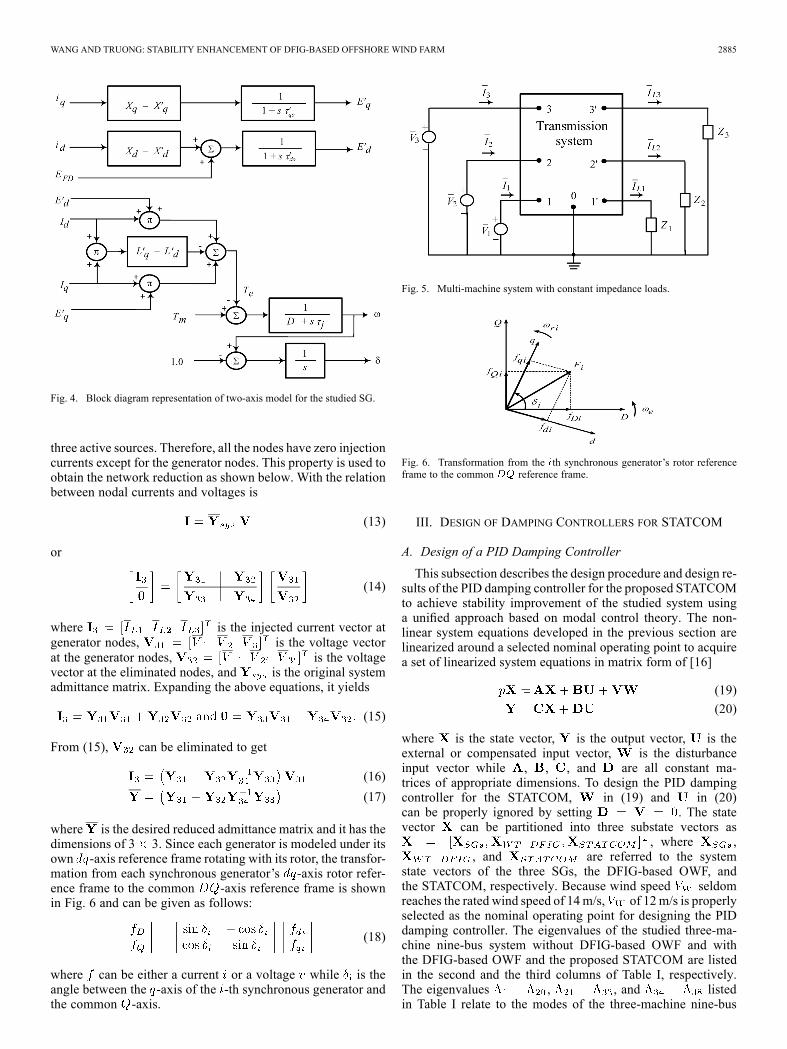
WANG AND TRUONG: STABILITY ENHANCEMENT OF DFIG-BASED OFFSHORE WIND FARM 2885
Fig. 4. Block diagram representation of two-axis model for the studied SG.
three active sources. Therefore, all the nodes have zero injectioncurrents except for the generator nodes. This property is used toobtain the network reduction as shown below. With the relationbetween nodal currents and voltages is
(13)
or
(14)
where is the injected current vector atgenerator nodes, is the voltage vectorat the generator nodes, is the voltagevector at the eliminated nodes, and is the original systemadmittance matrix. Expanding the above equations, it yields
(15)
From (15), can be eliminated to get
(16)
(17)
where is the desired reduced admittance matrix and it has thedimensions of 3 3. Since each generator is modeled under itsown -axis reference frame rotating with its rotor, the transfor-mation from each synchronous generator’s -axis rotor refer-ence frame to the common -axis reference frame is shownin Fig. 6 and can be given as follows:
(18)
where can be either a current or a voltage while is theangle between the -axis of the -th synchronous generator andthe common -axis.
Fig. 5. Multi-machine system with constant impedance loads.
Fig. 6. Transformation from the th synchronous generator’s rotor referenceframe to the common reference frame.
III. DESIGN OF DAMPING CONTROLLERS FOR STATCOM
A. Design of a PID Damping Controller
This subsection describes the design procedure and design re-sults of the PID damping controller for the proposed STATCOMto achieve stability improvement of the studied system usinga unified approach based on modal control theory. The non-linear system equations developed in the previous section arelinearized around a selected nominal operating point to acquirea set of linearized system equations in matrix form of [16]
(19)
(20)
where is the state vector, is the output vector, is theexternal or compensated input vector, is the disturbanceinput vector while , , , and are all constant ma-trices of appropriate dimensions. To design the PID dampingcontroller for the STATCOM, in (19) and in (20)can be properly ignored by setting . The statevector can be partitioned into three substate vectors as
, where ,, and are referred to the system
state vectors of the three SGs, the DFIG-based OWF, andthe STATCOM, respectively. Because wind speed seldomreaches the rated wind speed of 14m/s, of 12m/s is properlyselected as the nominal operating point for designing the PIDdamping controller. The eigenvalues of the studied three-ma-chine nine-bus system without DFIG-based OWF and withthe DFIG-based OWF and the proposed STATCOM are listedin the second and the third columns of Table I, respectively.The eigenvalues , , and listedin Table I relate to the modes of the three-machine nine-bus

2886 IEEE TRANSACTIONS ON POWER SYSTEMS, VOL. 28, NO. 3, AUGUST 2013
system, the DFIG-based OWF system, and the STATCOM,respectively. The following points can be found by examiningthe system eigenvalues listed in Table I.1) All modes of the system are almost fixed on the com-plex plane regardless the addition of the designed PIDdamping controller for STATCOM.
2) The modes and relating to the rotor angle de-viation between G1 to G2 and the rotor angledeviation between G1 to G3 , respectively, arechanged and these modes can be improved by dampingcontrollers.
The control block diagram of the STATCOM including the de-signed PID damping controller was shown in (i) of Fig. 3. ThePID damping controller with a first order wash-out term sensesthe rotor speed deviation of the G1 and G2 to generatea damping signal in order to improve the damping ratios oftwo modes ( and ) of studied system listed in Table I.Hence, the output signal in (23) is and isthe input vector. The transfer function of the PID dampingcontroller for the STATCOM in s domain is given by
(21)where is the time constant of the wash-out term while ,, and are the proportional gain, integral gain, and deriva-
tive gain of the damping controller, respectively. Taking theLaplace transformation of (19)–(20), the characteristic equa-tion of the closed-loop system containing the PID damping con-troller can be acquired. The input signal in domain can be ex-pressed by
(22)
Combining (21)–(22), it yields
(23)
The characteristic equation of the closed-loop system includingthe PID damping controller is given by
(24)
When two pairs of the specified mechanical modes ( and) are substituted into (24), the four parameters of the
PID controller can be obtained. The design results of the PIDdamping controller for the STATCOM are given as below.
Prespecified Eigenvalues
Parameters of the Designed PID Damping Controller
and s
The eigenvalues of the studied three-machine nine-bussystem containing the DFIG-based OWF and the proposedSTATCOM joined with the designed PID damping controllerare listed in the fourth column of Table I. It can be clearlyobserved that both and have been exactly positionedon the desired locations on the complex plane. Moreover,the damping ratios of and increase from 0.03842to 0.06060 and from 0.06824 to 0.11179, respectively. Somemajor constraints for selecting the assigned eigenvalues can be
TABLE IEIGENVALUES (rad/s) [DAMPING RATIOS] OF THE STUDIED
SYSTEM UNDER WIND SPEED OF 12 m/s
denotes exactly assigned eigenvalues
referred to [16] and [18]. According to the eigenvalue resultslisted in the fourth column of Table I and the four parametersof the designed PID damping controller of the STATCOMshown above, it can be concluded that the design results areappropriate to the studied system.
B. Design of an FLC Plus to the Designed PID
This section employs the technique of FLC theorem to designthe hybrid PID plus FLC damping controller shown in (ii) ofFig. 3. To design the FLC controller, the following fundamentaldesign steps for a FLC are employed and referred to [19] in-cluding: 1) fuzzification (FI), 2) decision-making logic (DML),3) defuzzification (DFI), and 4) knowledge base (KB). Fig. 7plots the block diagram of this hybrid control system, wherethe rotor-speed deviation between G1 and G2, , and itsderivative, , are fed to the FLC to generate three aux-iliary gains ( , , and ) for adding to the three gains ofthe designed PID controller ( , , and ) in the previoussubsection to control the phase angle of the STATCOM.These incremental gains from the FLC are updated to the gainsof the PID controller using the following rules [12]:
(25)
(26)
(27)
This paper utilizes the Sugeno-type fuzzy inference systemsince it works well with linear, optimization, and adaptive tech-niques [10], [11]. Seven linguistic variables for each input vari-able are used. These are NB (Negative Big), NM (NegativeMedium), NS (Negative Small), ZR (Zero), PS (Positive Small),PM (Positive Medium), and PB (Positive Big). There are alsoseven linguistic variables for output variable, namely, IB (In-crease Big), IM (Increase Medium), IS (Increase Small), KV(Keep Value), DS (Decrease Small), DM (Decrease Medium),

WANG AND TRUONG: STABILITY ENHANCEMENT OF DFIG-BASED OFFSHORE WIND FARM 2887
Fig. 7. Block diagram of the proposed hybrid PID plus FLC.
TABLE IICONTROL RULES OF THE STUDIED FLC
and DB (Decrease Big). The control rules subject to the twoinput signals and the output signal are listed in Table II.
IV. ROOT-LOCI ANALYSIS UNDERVARIOUS OPERATING CONDITIONS
This section presents the comparative root-loci analyzedresults of the system dominant modes when the proposedSTATCOM is with and without the designed PID dampingcontroller under widely changed wind speeds. The simulatedwind speed of the DFIG-based OWF is increased from4 m/s (cut-in wind speed of VSWT) to 24 m/s (cut-out windspeed of VSWT). Fig. 8(a) and (b) shows the correspondingroot-loci plots for the eigenvalues of the rotor angle betweenG1 to G2 and the rotor angle between G1 to G3under the selected wind speeds, respectively. It is found thatthese dominant modes can maintain stable operation and moveto leftward of the imaginary axis when the designed PID con-troller is in service. It means that the system is more stable whenthe proposed STATCOM is with the designed PID controller.
V. NONLINEAR MODEL SIMULATIONS
This section uses the nonlinear system model developed inSection II to compare the damping characteristics contributedby the proposed STATCOM joined with the designed PIDdamping controller and the hybrid PID plus FLC damping con-troller on stability improvement of the studied system under athree-phase short-circuit fault at bus 9 of Fig. 1. The three-phaseshort-circuit fault is suddenly applied to bus 9 at and iscleared at . Although this type of fault seldom occursin practical power systems, it is the most critical and the mostsevere fault to check whether the studied systems can withstandsuch severe system impacts. If the studied systems are stablewhen this severe fault is suddenly applied and is cleared bysome protective relays, it means that the studied systems haveability to remain stable operation when the systems are subjectto other faults such as single line-to-ground fault, line-to-linefault, etc. It is assumed that the DFIG-based OWF operates
Fig. 8. Root-loci results of the studied system versus various values of windspeed condition.
under a base wind speed of 12 m/s while the three-machinesystem operates under a stable condition as referred to [17]and [20]. The simulation results of the proposed system usingMATLAB/SIMULINK toolbox are presented in Fig. 9. Thisfigure plots the comparative transient responses of the studiedsystem with the proposed STATCOM without controller (bluelines), with the designed PID damping controller (red lines) andwith the hybrid PID plus FLC damping controller (black lines).It is clearly observed from the comparative transient simulationresults shown in Fig. 9 that the proposed STATCOM with thedesigned hybrid PID plus FLC damping controller can offerbetter damping characteristics than the designed PID dampingcontroller.The rotor speeds and the rotor angle derivations of the three
SGs are shown in Fig. 9(a)–(e), respectively. While terminalvoltages of each SG are plotted, respectively, in Fig. 9(g)–(i).For the responses of the DFIG-based OWF, the rotor speedand terminal voltage of the DFIG are plotted in Fig. 9(f) and(j), respectively. Fig. 9(k) presents the reactive power of theSTATCOM. It is obviously seen that the damping of the studiedsystem is still very poor with the stable time of about 6 s whenthe STATCOM is connected to the connected bus (bus 9). Bycoordinating with the designed PID damping controller withthe STATCOM, the studied system has better damping and itis stable at around .For more clearly, the percentage of improvement index
is used. The transient responses shown in Fig. 9 are assumed tobe similar to the transient responses of a typical second-ordersystem as shown in Fig. 10. The overshoot refers to an outputexceeding its steady-state value and percent of overshoot (POT)is an index to qualify the overshoot of a system, POT is calcu-lated as follows:
(28)
where and are the maximum and steady-state values of, respectively. Applying (28), the percentage of improvementof each figure is calculated and the result is also shown in
Fig. 9 when the studied system is without controller and withthe designed PID+FLC controller. It can be observed that only

2888 IEEE TRANSACTIONS ON POWER SYSTEMS, VOL. 28, NO. 3, AUGUST 2013
Fig. 9. Transient responses of the studied system under a three-phase short-circuit fault happened at bus 9. (a) Rotor speed of G1; (b) rotor speed of G2; (c) rotorspeed of G3; (d) rotor angle deviation between G1 to G2; (e) rotor angle deviation between G1 to G3; (f) rotor speed of equivalent DFIG-based OWF; (g) terminalvoltage of G1; (h) terminal voltage of G2; (i) terminal voltage of G3; (j) voltage of OWF; (k) reactive power supplied by STATCOM.
Fig. 9(k) (reactive power supplied by STATCOM) has a verysmall negative value for of 1%. However, most responsesshown in Fig. 9 demonstrate better damping and stable timewhen the studied system is with the designed PID+FLC con-troller.It shows that the proposed STATCOMwith the designed PID
and hybrid PID plus FLC damping controllers can supply properreactive power to the studied system and offer better dampingcharacteristics to quickly damp out the inherent oscillations ofthe studied system than the studied system without controller.
VI. CONCLUSION
This paper has presented the stability improvement of aDFIG-based OWF fed to a multi-machine system using aSTATCOM. The STATCOM is proposed and is connected tothe connected bus of the OWF to the multi-machine system.To supply the adequate reactive power to the system, a PID
Fig. 10. Transient response of a typical second-order system.
damping controller for the STATCOM has been designed byusing a modal control theory to assign two dominant modesof the studied system to the desired locations on the complex

WANG AND TRUONG: STABILITY ENHANCEMENT OF DFIG-BASED OFFSHORE WIND FARM 2889
plane. Root-loci plots under various wind speed operatingconditions have been carried to show the effectiveness of thedesigned PID damping controller. Moreover, for improvingthe performance of the studied system with the designed PID,a hybrid PID plus FLC damping controller is also designed.Comparative time-domain simulations of the studied systemsubject to a three-phase short-circuit fault at the connectedbus have been systematically performed to demonstrate theeffectiveness of the proposed STATCOM joined with the twodesigned damping controllers on suppressing inherent oscil-lations of the studied system. It can be concluded from thesimulation results that the proposed STATCOM joined withthe designed hybrid PID plus FLC damping controller has thebest damping characteristics to improve the performance ofthe DFIG-based OWF fed to the studied multi-machine systemunder different operating conditions.
REFERENCES
[1] R. Pena, J. C. Clare, and G. M. Asher, “Doubly fed induction gener-ator using back-to-back PWM converters and its application to variablespeed wind-energy generation,” Proc. Inst. Elect. Eng., Elect. PowerAppl., vol. 143, no. 3, pp. 231–241, May 1996.
[2] L.Wang andK.-H.Wang, “Dynamic stability analysis of a DFIG-basedoffshore wind farm connected to a power grid through an HVDC link,”IEEE Trans. Power Syst., vol. 26, no. 3, pp. 1501–1510, Aug. 2010.
[3] L. Wang and L.-Y. Chen, “Reduction of power fluctuations of a large-scale grid-connected offshore wind farm using a variable frequencytransformer,” IEEE Trans. Sustain. Energy, vol. 2, no. 3, pp. 226–234,Apr. 2011.
[4] E. Muljadi, T. B. Nguyen, andM. A. Pai, “Impact of wind power plantson voltage and transient stability of power systems,” in Proc. IEEEEnergy 2030 Conf., Nov. 2008, pp. 1–7.
[5] O. Anaya-Lara, A. Arulampalam, G. Bathurst, F. M. Hughes, and N.Jenkins, “Transient analysis of DFIG wind turbines in multi-machinenetworks,” in Proc. 18th Int. Conf. Exhib. Electricity DistributionCIRED, Jun. 2005, pp. 1–5.
[6] K. E. Okedu, S. M. Muyeen, R. Takahashi, and J. Tamura, “Improve-ment of fault ride through capability of wind farms using DFIG con-sidering SDBR,” in Proc. 14th Eur. Conf. Power Electronics and Ap-plications, Sep. 2011, pp. 1–10.
[7] N. G. Hingorani and L. Gyugyi, Understanding FACTS; Concepts andTechnology of Flexible AC Transmission Systems. New York, NY,USA: IEEE Press, 2000.
[8] B. Pokharel and W. Gao, “Mitigation of disturbances in DFIG-basedwind farm connected to weak distribution system using STATCOM,”in Proc. North American Power Symp. (NAPS), Sep. 26–28, 2010, pp.1–7.
[9] G. Cai, C. Liu, Q. Sun, D. Yang, and P. Li, “A new control strategy toimprove voltage stability of the power system containing large-scalewind power plants,” in Proc. 4th Int. Conf. Electric Utility Deregula-tion and Restructuring and Power Technologies (DRPT), Jul. 2011, pp.1276–1281.
[10] M. N. Eskander and S. I. Amer, “Mitigation of voltage dips and swellsin grid-connected wind energy conversion systems,” in Proc. ICCAS-SICE, Aug. 2009, pp. 885–890.
[11] L. O. Mak, Y. X. Ni, and C. M. Shen, “STATCOM with fuzzy con-trollers for interconnected power systems,”Elect. Power Syst. Res., vol.55, no. 2, pp. 87–95, Aug. 2000.
[12] M. N. Uddin and R. S. Rebeiro, “Improved dynamic and steady stateperformance of a hybrid speed controller based IPMSMdrive,” inProc.IEEE Industry Applications Society Annual Meeting (IAS), Oct. 9–13,2011, pp. 1–8.
[13] L. Reznik, O. Ghanayem, and A. Bourmistrov, “PID plus fuzzy con-troller structures as a design base for industrial applications,” Eng.Appl. Artif. Intell., vol. 13, no. 4, pp. 419–430, Aug. 2000.
[14] S. M. Muyeen, M. H. Ali, R. Takahashi, T. Murata, J. Tamura, Y.Tomaki, A. Sakahara, and E. Sasano, “Transient stability analysisof wind generator system with the consideration of multi-mass shaftmodel,” in Proc. Int. Conf. Power Electronics and Drives Systems,Jan. 16–18, 2006, vol. 1, pp. 511–516.
[15] P. Cartwright, L. Holdsworth, J. B. Ekanayake, and N. Jenkins, “Co-ordinated voltage control strategy for a doubly-fed induction generator(DFIG)-Based wind farm,” Proc. Inst. Elect. Eng., Gener., Transm.,Distrib., vol. 151, no. 4, pp. 495–502, Aug. 2004.
[16] L. Wang and C.-T. Hsiung, “Dynamic stability improvement of anintegrated grid-connected offshore wind farm and marine-current farmusing a STATCOM,” IEEE Trans. Power Syst., vol. 26, no. 2, pp.690–698, May 2011.
[17] P. M. Anderson and A. A. Fouad, Power System Control and Sta-bility. Ames, IA, USA: Iowa State Univ. Press, 1977.
[18] J. Ma, Z. Y. Dong, and P. Zhang, “Eigenvalue sensitivity analysis fordynamic power system,” in Proc. Int. Conf. Power System Technology,Oct. 22–26, 2006, pp. 1–7.
[19] C. C. Lee, “Fuzzy logic in control system: Fuzzy logic controller, PartI and II,” IEEE Trans. System, Man, Cybern., vol. 20, pp. 404–435,Mar./Apr. 1990.
[20] P. W. Sauer and M. A. Pai, Power System Dynamics and Stability.Englewood Cliffs, NJ, USA: Prentice Hall, 1998.
Li Wang (S’87–M’88–SM’05) received the Ph.D.degree from the Department of Electrical Engi-neering, National Taiwan University, Taipei City,Taiwan, in June 1988.He has been an associated professor and a pro-
fessor at the Department of Electrical Engineering,National Cheng Kung University, Tainan City,Taiwan, in 1988 and 1995, respectively. He was avisiting scholar of the School of Electrical Engi-neering and Computer Science, Purdue University,West Lafayette, IN, USA, from February 2000 to
July 2000, and the School of Electrical Engineering and Computer Science,Washington State University, Pullman, WA, USA, from August 2003 toJanuary 2004. He was a research scholar of the Energy Systems ResearchCenter (ESRC), the University of Texas at Arlington (UTA), Arlington, TX,USA, from July 2008 to January 2009. At present, his research interests includepower systems dynamics, power system stability, AC machine analyses, andrenewable energy.
Dinh-Nhon Truong was born in Quang namProvince, Vietnam, on December 3, 1979. Hereceived the B.S. and M.S. degrees from the De-partment of Electrical and Electronics Engineering,University of Technical Education, Ho Chi MinhCity, Vietnam, in April 2003 and May 2005, respec-tively. He is currently pursuing the Ph.D. degree atthe Department of Electrical Engineering, NationalCheng Kung University, Tainan, Taiwan.His research interests are grid-connected wind
power systems and marine-current energy conver-sion systems.