27.0 public safety - maine
TRANSCRIPT

Weaver Wind Project
MDEP Site Location of Development/NRPA Combined Application SECTION 27: PUBLIC SAFETY
27-1
27.0 PUBLIC SAFETY
27.1 INTRODUCTION
A proposed generating facility must demonstrate that it has sufficient project setbacks and other
considerations to adequately protect public safety.1
27.2 TURBINE DESIGN CERTIFICATION
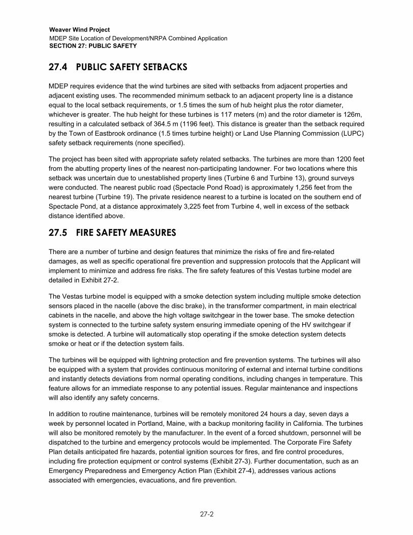
The project will be constructed with 3.45 MW wind turbine generators (Vestas V126). The conformity of
Vestas V126 with International Electrotechnical Commission standards has been certified by Det Norske
Veritas (Exhibit 27-1).
27.3 SAFETY CONTROLS
This Vestas model is a 3-bladed, horizontal-axis, upwind, variable-speed, pitch- regulated turbine. The
speed and power output is controlled primarily by an active, hydraulic pitch regulation system. The blades
are mounted on pitch bearings and can be feathered for shutdown purposes. Each blade has its own
independent pitching mechanism capable of feathering the blade under any operating condition. The
independent pitch mechanism on each of the blades provides for redundancy.
The generator rpm and the main shaft rpm of both Vestas models are registered by inductive sensors and
calculated by the wind turbine controller to protect against overspeed and rotating errors. In addition, the
turbine is equipped with a safety programmable logic controller (PLC), an independent computer module
that measures the rotor rpm. In case of an overspeed situation, the safety PLC activates the emergency
feathered position (full feathering) of the three blades independently of the turbine controller.
The main brake on the turbine is aerodynamic. Stopping the turbine is done by full feathering of the three
blades (individually turning each blade). Each blade has a hydraulic accumulator to supply power for
turning the blade. In addition, there is a mechanical disc brake on the high-speed shaft of the gearbox
with a dedicated hydraulic system. The mechanical brake is only used as a parking brake and when
activating the emergency stop buttons.
The wind turbines operate automatically and are self-starting when the wind speed reaches an average of
3 meters per second (m/s) or approximately 6.7 miles per hour (mph). The output increases with wind
speed until wind speed reaches approximately 10.5 meters per second (m/s [22 mph]). At this point, the
power is regulated at the fully controlled power of 3.3 MW.
If the average wind speed exceeds the maximum operational limit of 27.5 m/s, the wind turbines will
automatically shut down by feathering of the blades. The aerodynamic brakes are redundant due to the
ability to brake with one blade. When the average wind speed drops back below 20.5 m/s, the system
automatically resets. The V126 turbine is designed to withstand gusts of up to 59.5 m/s (133 mph).
1 38 MRSA §3455; 06-096 CMR 382(5).
Weaver Wind Project
MDEP Site Location of Development/NRPA Combined Application SECTION 27: PUBLIC SAFETY
27-2
27.4 PUBLIC SAFETY SETBACKS
MDEP requires evidence that the wind turbines are sited with setbacks from adjacent properties and
adjacent existing uses. The recommended minimum setback to an adjacent property line is a distance
equal to the local setback requirements, or 1.5 times the sum of hub height plus the rotor diameter,
whichever is greater. The hub height for these turbines is 117 meters (m) and the rotor diameter is 126m,
resulting in a calculated setback of 364.5 m (1196 feet). This distance is greater than the setback required
by the Town of Eastbrook ordinance (1.5 times turbine height) or Land Use Planning Commission (LUPC)
safety setback requirements (none specified).
The project has been sited with appropriate safety related setbacks. The turbines are more than 1200 feet
from the abutting property lines of the nearest non-participating landowner. For two locations where this
setback was uncertain due to unestablished property lines (Turbine 6 and Turbine 13), ground surveys
were conducted. The nearest public road (Spectacle Pond Road) is approximately 1,256 feet from the
nearest turbine (Turbine 19). The private residence nearest to a turbine is located on the southern end of
Spectacle Pond, at a distance approximately 3,225 feet from Turbine 4, well in excess of the setback
distance identified above.
27.5 FIRE SAFETY MEASURES
There are a number of turbine and design features that minimize the risks of fire and fire-related
damages, as well as specific operational fire prevention and suppression protocols that the Applicant will
implement to minimize and address fire risks. The fire safety features of this Vestas turbine model are
detailed in Exhibit 27-2.
The Vestas turbine model is equipped with a smoke detection system including multiple smoke detection
sensors placed in the nacelle (above the disc brake), in the transformer compartment, in main electrical
cabinets in the nacelle, and above the high voltage switchgear in the tower base. The smoke detection
system is connected to the turbine safety system ensuring immediate opening of the HV switchgear if
smoke is detected. A turbine will automatically stop operating if the smoke detection system detects
smoke or heat or if the detection system fails.
The turbines will be equipped with lightning protection and fire prevention systems. The turbines will also
be equipped with a system that provides continuous monitoring of external and internal turbine conditions
and instantly detects deviations from normal operating conditions, including changes in temperature. This
feature allows for an immediate response to any potential issues. Regular maintenance and inspections
will also identify any safety concerns.
In addition to routine maintenance, turbines will be remotely monitored 24 hours a day, seven days a
week by personnel located in Portland, Maine, with a backup monitoring facility in California. The turbines
will also be monitored remotely by the manufacturer. In the event of a forced shutdown, personnel will be
dispatched to the turbine and emergency protocols would be implemented. The Corporate Fire Safety
Plan details anticipated fire hazards, potential ignition sources for fires, and fire control procedures,
including fire protection equipment or control systems (Exhibit 27-3). Further documentation, such as an
Emergency Preparedness and Emergency Action Plan (Exhibit 27-4), addresses various actions
associated with emergencies, evacuations, and fire prevention.

Weaver Wind Project
MDEP Site Location of Development/NRPA Combined Application SECTION 27: PUBLIC SAFETY
27-3
The clearing associated with construction of turbine pads and permanent impervious surfaces associated
with crane pads creates an area around each turbine that is generally free of materials that could be
ignited in the unlikely event of a turbine fire. Additionally, access roads and crane paths serve as “fire
breaks”, thereby preventing the spread of any fire to adjacent areas.
Portable fire extinguishers will be properly located throughout the facility, and employee vehicles will be
equipped with portable fire extinguishers. A handheld 5-6 kilogram (kg) carbon dioxide (CO2) fire
extinguisher, first aid kit, and fire blanket are required to be located in the nacelle during service and
maintenance.
• A handheld 5-6 kg CO2 fire extinguisher is required only during service and maintenance
activities, unless a permanently mounted fire extinguisher located in the nacelle is mandatorily
required by authorities;
• First aid kits are required only during service and maintenance activities; and
• Fire blankets are required only during non-electrical hot work activities.
Longroad’s team has developed and successfully implemented fire protection plans at five operating
facilities in Maine.
The Applicant will regularly train contractors and employees on fire prevention and response protocols.
Trainees will demonstrate an understanding of protocols and proficiency in using all equipment prior to
performing work requiring identified fire prevention equipment.
The Applicant will also establish emergency communications and response protocols with emergency
response providers to ensure timely notification, access and coordination if the event of an incident. An
example of an Emergency Preparedness and Emergency Action Plan is included as Exhibit 27-4; a
project specific plan will be developed prior to operation.
The Maine Forest Service, which provides fire response services and has direct experience with the
nearby Bull Hill Wind Project, has indicated that the project will have little if any impact on services
provided in the region and need for additional fire protection services will be minimal and consistent with
the services currently provided (Exhibit 27-5). Additionally, the Eastbrook Volunteer Fire Department
indicated that the project will have minimal impacts or no on the fire protection services they provide. The
Osborn Volunteer Fire Department was also consulted regarding fire and emergency services and
indicated a willingness to assist the project if needed. (Exhibit 27-5).
Local outreach and training will continue following project construction. By way of example, the adjacent
Bull Hill Wind Project has been visited by the Maine Emergency Management Agency to provide a site
tour for members not yet familiar with wind energy facilities and to discuss a mock emergency response
drill. Longroad team members also met with more than 60 local emergency responders through the
Hancock County Emergency Responders group to discuss emergency response for the Bull Hill Wind
Project.
In summary, fire risk from the proposed project is minimal. There will be appropriate protective measures
in place to reduce the risk of fires or fire related damages. Furthermore, appropriate training has been
provided to local and state emergency responders, and education efforts will continue.

Weaver Wind Project
MDEP Site Location of Development/NRPA Combined Application SECTION 27: PUBLIC SAFETY
27-4
27.6 LIGHTING
The project will install FAA complaint lighting, which is expected to require lighting on each turbine and
the meteorological towers.
If approved by FAA, the project will use a radar-assisted lighting system. Radar-assisted lighting is
designed to minimize the effects of nighttime safety lighting of turbines. Such systems allow obstruction
lights to remain off at all times unless an aircraft is operating in the vicinity of the site, thus greatly
reducing the time that nighttime lighting is visible.
The FAA has not yet issued blanket approval for the use of radar- assisted lighting systems for
commercial wind projects and is reviewing them on a case by case basis. The project will install and
operate standard lighting while it awaits FAA review and approval of an Aircraft Detection Lighting System
(ADLS) following the technical specifications of the relevant FAA Advisory Circular.2 If the FAA grants
approval, the project will be fitted with radar-assisted lighting provided such systems are technically
feasible and economically viable. Radar-assisted lighting will be installed within one year of the FAA
approval; this time period may be extended if there are delays in obtaining any required permits
associated with the installation.
In compliance with FAA safety requirements, the project will retain the ability to keep standard nighttime
lighting of turbines on in the event FAA does not approve ADLS for this project; there is a malfunction with
the radar-assisted system; or during periods of maintenance and repair.
2 FAA Advisory Circular 70/7460-1L, Chapter 14 (10/07/2016)

Weaver Wind Project
MDEP Site Location of Development/NRPA Combined Application SECTION 27: PUBLIC SAFETY
Exhibit 27-1
Design Certification


VESTAS PROPRIETARY NOTICE: This document contains valuable confidential information of Vestas Wind Systems A/S. It is protected by copyright law as an unpublished work. Vestas reserves all patent, copyright, trade secret, and other proprietary rights to it. The information in this document may not be used, reproduced, or disclosed except if and to the extent rights are expressly granted by Vestas in writing and subject to applicable conditions. Vestas disclaims all warranties except as expressly granted by written agreement and is not responsible for unauthorized uses, for which it may pursue legal remedies against responsible parties.


Weaver Wind Project
MDEP Site Location of Development/NRPA Combined Application SECTION 27: PUBLIC SAFETY
Exhibit 27-2
Fire Safety Features of V126 Turbines


September 3, 2018
Jeremy Law Longroad Energy
30 Danforth St, Suite 210 Portland, ME 04101
RE: Fire Safety of Vestas V126-3.45MW de-rated to 3.3MW
Mr. Law,
Thank you for your recent inquiry about the risk of fire associated with the Vestas V126-3.3 MW wind turbine generator models for Longroad Energy projects in the State of Maine. Safety is Vestas’ number one priority and Vestas takes the risk of fires very seriously. As described below, the V126-3.3 MW turbines are designed to minimize this risk.
Electrical Equipment The importance of safety at Vestas means electrical safety is a major design focus for all Vestas wind turbines, including the V112/V117/V126-3.3 MW models. Proper design and manufacture of electrical systems is essential for protection of personnel and minimizing risk of fires.
One source of potential fire in wind turbines is the high-voltage transformer, which in many other turbine models are oil-filled and hence flammable. The Vestas V112/V117/V126-3.3 MW turbines eliminate this oil-based risk by using dry transformers that are air cooled and physically separated from other components in the nacelle. This minimizes the risk of an electrical arc and fire, and is the preferred configuration of the United States National Fire Protection Association (NFPA) code 850 (section 5.1.5.1).
Vestas turbines utilize an integrated monitoring system to monitor hundreds of signals throughout the turbine, including temperature, current, and voltage measurements, to ensure that the turbine is operating completely within normal bounds. The turbine is designed to safely de-rate or shut down if any parameter exceeds pre-set thresholds. Such use of an integrated monitoring system is recommended by the Confederation of Fire Protection Associations in Europe (CFPA E) document “Wind turbines fire protection guideline” (sections 4, 5.1.2, and 5.1.6).
In the case of an electrical arc incident, arc detectors are positioned to instantaneously detect the arc, safely shut down the turbine, and open the main switchgear. This system acts independently of the control system, and removes the energy source for the fire before it has a chance to ignite. The shutdown causes the blades to automatically pitch to an aerodynamically neutral position using stored hydraulic energy, causing the rotor to come to a complete stop within seconds, without requiring use of a mechanical disc brake. This is in accordance with CFPA E (section 5.1.2) and NFPA (section 10.5.1.3) recommendations.
There are multiple smoke and heat detectors located inside the nacelle as recommended by the CFPA E (section 5.2.1). The smoke detectors act independently from the turbine controller and automatically shut down the turbine and open the main switchgear of the turbine using the same procedures as the arc detectors. Additionally, the fire protection system can operate after the wind turbine is disconnected from the grid to give alarms to the personnel present in the wind turbine and send data to the wind turbine controller.
A Fire Suppression System (FSS) is also present in the nacelle controller cabinet, converter cabinet, and transformer room. The system consists of a pressure cylinder, containing the extinguishing agent 3M Novec 1230, (a colorless, low odor fluid, low in toxicity, electrically non-conductive, and an extremely effective fire suppression agent) and a pipe system with nozzles. The fire protection strategy is to individually detect and extinguish potential fires in the targeted compartments before the fire spreads to other compartments. The FSS is activated by the Vestas Smoke and Heat Detection System, upon which it disperses the suppression fluid into the targeted compartment via the compartment

specific nozzle .
Manufacturing quality is essential for ensuring the effectiveness of the turbine’s electrical safety systems. Vestas uses state-of-the-art quality systems in its manufacturing facilities, and cascades many of these requirements to sub- suppliers, to ensure that product quality enhances fire safety. Sophisticated systems ensure that bolted connections are at the correct torque value, cable connections are secure, and the entire turbine functions properly before leaving the manufacturing facilities. Each turbine undergoes full-scale testing both in the factory and at the site before it is released for operation. Such quality systems are recommended by the CFPA E to ensure safe operation of wind turbines for their service life (section 5.4).
Lightning Strike The V112/V117/V126-3.3 MW are designed according to lightning protection level 1 of the International Electrotechnical Commission (IEC) 62305 standard; the highest protection level, corresponding to safe conduction of lightning strikes up to 200 kA; this is the recommended level according to the CFPA E (section 5.1.1). The lightning protection system of the V112/V117/V126-3.3 MW turbines is a proven design, refined over many previous turbine models, incorporating design best practices to ensure safe operation for the duration of the turbine’s life. During the turbine design phase Vestas validated the performance of the lightning protection system according to all applicable IEC test standards in state-of-the-art facilities in Europe. This provided verification that the system is designed to transfer lightning strikes safely to ground, no matter where the turbine has been struck. The lightning protection system extends from the tips of the blades, around the entire nacelle, the tower, and into the foundation earthing system. This comprehensive approach to lightning protection is recommended by the CFPA E (section 5.1.1).
Hot Surfaces Hot surfaces are kept to a minimum in the V112/V117/V126-3.3 MW turbines. In order to bring the rotor to a safe stop, no matter what the wind conditions, the hydraulic pitch system is used, not the mechanical disc brake. This method of operation is reliable and proven across more than 20 years of Vestas wind turbine designs. Each blade of the wind turbine has its own pitch actuator, and in case of problems with the pitch system only two blades are required to bring the rotor to a complete stop.
The mechanical disc brake in the V112/V117/V126-3.3 MW is only used for service activities (stopping rotation of the rotor so that the rotor lock pins can be installed) or when a technician physically presses the emergency stop button. Even during an emergency stop, the mechanical disc brake is only applied at low rotational speeds to limit the amount of heat build-up, and the brake is automatically released after approximately 30 minutes so that brake friction doesn’t cause excessive heat. The disc brake is covered, according to the recommendations of the CFPA E (section 3.3.3)
Work Involving Fire Hazards Welding, burning, grinding, and other work involving heat sources are not part of the standard installation or maintenance plan of the turbine. Such work typically takes place in the factory during the manufacturing process, or in workshops in the case of component repair.
In the rare instance that “hot work” is required to be performed in the turbine (hot work in the turbine is avoided if possible) Vestas’ work instructions include numerous requirements to ensure that personnel and equipment are safe. Precautions include ensuring the work area is free of any flammable materials, sufficient ventilation, use of fire blankets, ensuring that extinguishers are on hand, and clean-up and inspection of the work place after the job is finished. Technicians must complete appropriate documentation and obtain permits from site management before engaging in any hot work. Limitation and regulation of hot work is recommended by the CFPA E (section 5.1.5) and NFPA (section 16.3(5)).
Combustible Materials The use of flammable materials in the turbine cannot be avoided for practical reasons, but Vestas makes efforts to manage these risks appropriately. For example, oil is used in the hydraulic pitch system and to lubricate the gearbox;
so the turbine continuously monitors oil pressures and oil levels to ensure that there are no leaks. If a leak is detected the turbine is automatically shut down and technicians need to visit the turbine and repair the issue before it can be re-started.
Materials that are not essential to the operation of the turbine are not left in the machine, including cleaning solvents, rags, papers, garbage, etc. This keeps the amount of flammable materials in the turbine to a minimum, as recommended by the CFPA E (section 5.1.3 and 5.1.4). Smoking is not allowed in Vestas wind turbines, in accordance with CFPA E recommendations (section 5.1.7).
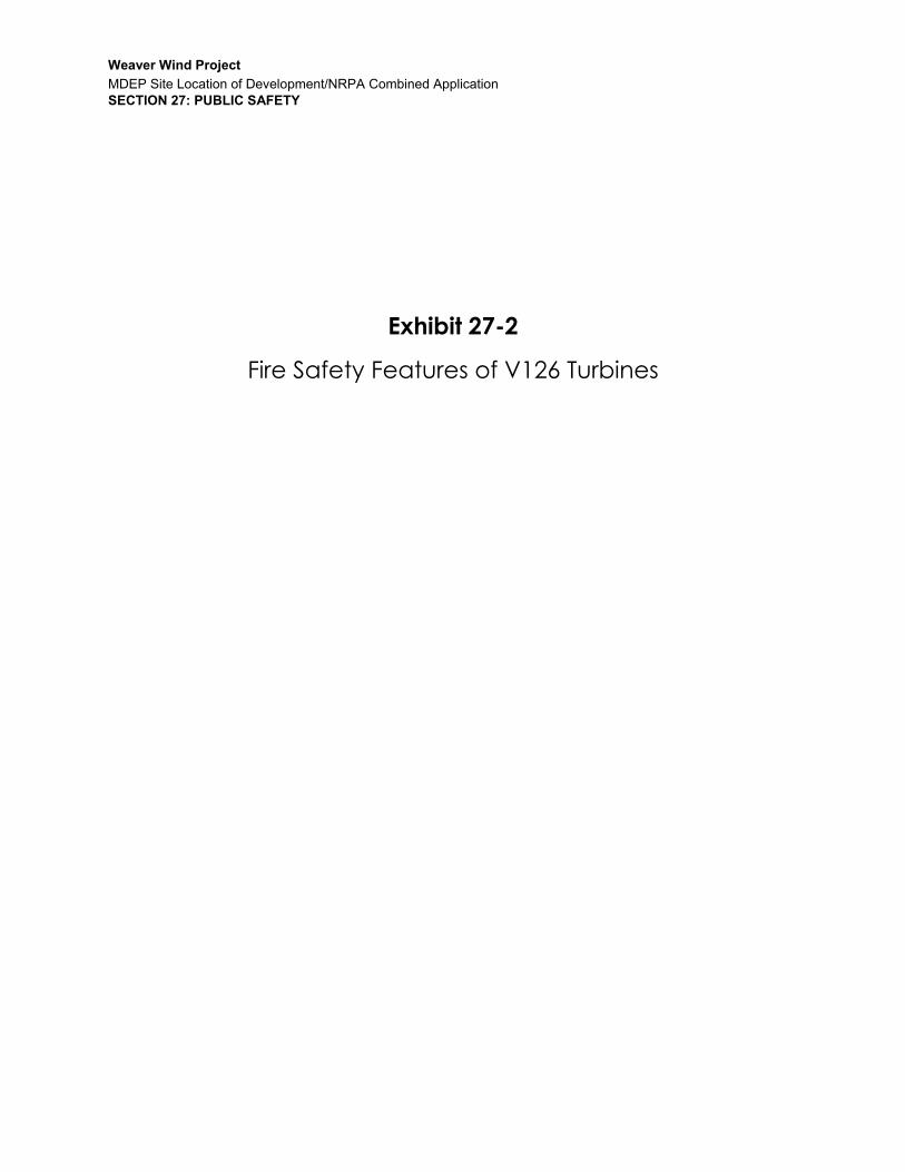
Fire Fighting Technicians have a standard safety kit that they bring when working on the turbines (in addition to their standard personal protective equipment including safety boots, safety glasses, gloves, fall arrest equipment, etc.). This includes a first aid kit, 5-6 kg CO2 fire extinguisher, and emergency descent device. Fire blankets are required if any hot work is to be performed. These items are stored at the site office, not the turbine, because it is easier to maintain and inspect them on the ground than during turbine visits, which may be as long as 1 year apart if there are no turbine operation faults.
Technicians receive training and regular refresher courses on the proper usage of these items in the case of emergency situations, as the CFPA E recommends (section 5.1.8). Prior to each turbine visit technicians are required to check that fire extinguishers are in good condition and are not late on inspections.
Maintenance The V112/V117/V126-3.3 MW turbines are designed with much more working space than other wind turbine models to ensure that technicians have enough open space to safely maintain, repair, and replace equipment as needed – an increase of 60% versus previous Vestas turbine models. In addition to fluorescent lighting along the entire height of the tower, and throughout the nacelle, skylights provide additional lighting during daytime hours. This allows technicians to properly see their work, ensure high quality, and clean up when the work is done; aspects that have been recognized by the CFPA E as important to fire safety (section 3.3.7)
While working on the turbine, technicians keep fire safety in mind at all times. Before performing any work, technicians prepare thorough planning documents to describe the activities that are planned to take place in the turbine and the potential hazards associated with these tasks, including confined space and risk of fire assessments.
During annual service visits, technicians inspect and maintain a variety of components in the turbine that ensures safe operation. For example, electrical connections are inspected and re-tightened, oil filters are replaced, the disc brake is inspected, arc detectors are tested and cleaned, the transformer is inspected and cleaned, etc. These maintenance activities are considered by the CFPA E to be important steps that mitigate the risk of fires (section 5.1.6). Technicians are qualified to perform this work after attending regular and extensive training sessions at our North American training center in Portland, Oregon as well as on the job training and certification activities.
Conclusion Vestas takes fire safety very seriously, which is shown in the design of the V112/V117/V126-3.3 MW wind turbines. Every aspect of the turbine from layout, to electrical design, to maintenance requirements have been developed to ensure years of safe and trouble-free operation. This wind turbine is an excellent fit for First Wind’s wind projects and is designed to safely provide years of clean energy to the residents of Maine.
Kind regards,
Thomas Allain Technical Bid Manager Vestas-American Wind Technology, Inc.


Weaver Wind Project
MDEP Site Location of Development/NRPA Combined Application SECTION 27: PUBLIC SAFETY
Exhibit 27-3
Corporate Fire Safety Plan


Page 1 of 7 Document # OPS-PRC-F-002-REV2
Fire Safety Plan
Longroad Energy
Document # OPS-PRC-F-002-REV2
Prepared by: C Cote
Date Created: 1/09/18
Revised by: Kim Primerano
Last day revised: 1/23/18

Page 2 of 7 Document # OPS-PRC-F-002-REV2
Table of Contents 1. Disclaimer .............................................................................................................................................. 2
2. Approval and Signoff ............................................................................................................................. 2
3. Revision History .................................................................................................................................... 2
4. Regulatory Requirements ..................................................................................................................... 3
5. Objective ............................................................................................................................................... 3
6. Definitions ............................................................................................................................................. 4
7. Document Body .................................................................................................................................... 4
8. Plan…………………………………………………………………………………………………………………………………………………4
1. DisclaimerThis document is proprietary and confidential in nature and is not intended for use or distribution
outside of Longroad Energy. If such distribution is required, is must be done with the consent of the
Authorized Person who approved this document. This document shall not transfer nor be used by
parties other than Longroad Energy unless explicitly called out in other agreements.
2. Approval and Signoff
Authorized Person
Name (Printed): Claude Cote
Company Title:
Director Safety & Compliance
Signature Date
3. Revision History
Revision Date Revision Number Editor
Approved By Description of Changes
1/09/18 1.0 C Cote All new, format
1/23/18 2.0 Kim Primerano Edited numbers & formatting
01/23/2018

Page 3 of 7 Document # OPS-PRC-F-002-REV2
4. Regulatory RequirementsRequirement Description Cross Reference
OSHA 1910.39 Fire Prevention Plans
5. ObjectiveThe Objective of this Plan is to help control or reduce the possibility of fire and to specify the type of
equipment to use in the event of fire in a Longroad Energy location. This plan addresses the
following issues:
5.1 Major anticipated fire hazards.
5.2 Potential ignition sources for fires and their control procedures.
5.3 The type of fire protection equipment or systems that can control a fire.
This plan requires that all affected personnel be informed of the plan's purpose, preferred means of
reporting fires and other emergencies, types of evacuations to be used in various emergency
situations, and the fire detection and alarm system. The plan is tied to the Tower Rescue Procedure
where procedures are described for the emergency escape from a WTG.
It is important to note that fire extinguishers are designed for emergency escape purposes only. You
should never attempt to extinguish a fire if it is beyond the incipient stage, if you do not know what
is burning or fueling the fire, or if you can safely evacuate from the fire without the use of a fire
extinguisher.
6. Applicability/ResponsibilityThis applies to in locations. The responsibilities of this plan are:
6.1 HS Department or Designee 6.1.1 Annually review this procedure and update as necessary. 6.1.2 Provide general Fire Protection guidance. 6.1.3 Review incident patterns relating to this plan.
6.2 Supervisors/Managers 6.2.1 Ensure the implementation of this Fire Protection program. 6.2.2 Use these procedure guidelines to minimize fire hazards when assigning work
activities to site employees. 6.2.3 Verify employees are complying with this procedure.
6.3 Employees
6.3.1 Comply with all parts of this plan.

Page 4 of 7 Document # OPS-PRC-F-002-REV2
7. DefinitionsTerm Definition
HSE Health, Safety, and Environmental
Location Longroad Energy owned, operated or otherwise staffed location or facility.
Location Head The person designated by Longroad Energy to have control of or be the highest ranked person at a Longroad Energy Location.
Location HSE Coordinator
The person designated at each location that is responsible to ensure that the HSE Program is properly administered at the location.
EAP Emergency Action Plan. The facility EAP will have instructions on emergency meeting locations and emergency contact information
WTG Wind Turbine Generator
8. Plan8.1 Workplace Fire Hazards
8.1.1 The first step towards an effective Fire Safety Plan is to assure that hazardous
accumulations of combustible waste materials are controlled so that a fast-developing fire, rapid
spread of toxic smoke, or an explosion will not occur.
8.1.2 Fire prevention measures must be developed for all fire hazards found. Once
employees are made aware of the fire hazards in their work areas, they must be trained in the
fire prevention measures developed and use them in the course of their work. For example, oil-
soaked rags must be treated differently than general paper trash. In addition, large
accumulations of waste paper or corrugated boxes, etc., can pose a significant fire hazard.
Accumulations of materials that can cause large fires or generate dense smoke that are easily
ignited or may start from spontaneous combustion are the types of materials with which this
fire safety plan is concerned. Matches, welder’s sparks, cigarettes and similar low-level energy
ignition sources may easily ignite such combustible materials.
8.1.3 All WTG and Solar workers should be monitor housekeeping to reduce and
control fuel source hazards such as accumulation of flammable and combustible materials like
trash, oily rags, or any other fire hazard.
8.2 Emergency Evacuation in the Event of a Fire
8.2.1 Follow posted evacuation routes for your location and proceed to the
emergency meeting location. Wait for instructions from the Location Head once everyone is at
the emergency meeting location and a head count is performed.
8.2.2 The following matrix explains the recommended evacuation procedure in the
event of a fire at an elevated location at a wind facility.

Page 5 of 7 Document # OPS-PRC-F-002-REV2
Fire Location Evacuation Method
Fire at the base of climbing structure of
elevated location with workers above
Evacuate the elevated location to ground level.
Immediately evacuate to a safe distance from
the elevated location
Fire in WTG Nacelle with workers below Immediately descend the ladder to ground
level and evacuate to a safe distance from the
WTG
Fire in the WTG Nacelle with workers above or
exterior
Evacuate outside the WTG to the ground level
to a safe distance from the WTG
8.3 Fire Protection Equipment
8.3.1 Most office locations are equipped with automatic water sprinklers. These systems
should be maintenanced on a regular basis to ensure they will operate in the event of a fire.
8.3.2 All office locations are also equipped with wall mounted dry chemical ABC portable fire
extinguishers. The size may vary from 5lb to 20lb.
8.3.3 Most service vehicles carry portable fire extinguishers of either ABC or CO₂ type ranging
from 3lb to 10lb.
8.3.4 Some electronic equipment rooms are protected by non-water based automatic
extinguishers. These may include FM200, CO2 or other chemicals. It is important for personnel who
regularly access these locations to be familiar with the MSDS of the chemicals in these extinguishers so
they know what to do in the event they are released.
8.3.5 The Fire Protection Equipment devices preferred in the tower and Nacelle of the WTG
are CO₂ (Carbon Dioxide) or KNO₃ (potassium nitrate) portable fire extinguishers. These extinguishers
are designed for use on Class A (combustible solids), Class B (liquid) and Class C (electrical) fires. They
have been selected for this application because they are most effective for the types of fires anticipated
in a WTG. Dry chemical ABC fire extinguishers, although effective for this application, may present
additional safety hazards (eye and respiratory irritants) when used in a confined area.
8.3.6 Portable Fire Extinguisher Use
8.3.6.1 Should it be necessary to use a portable fire extinguisher for emergency escape
purposes:
8.3.6.2 Stand approximately 6 – 8 feet away (on the upwind side if possible) from the
fire. This will minimize blowing away burning material or not getting enough extinguishing agent
onto the fire.
8.3.6.3 Pull the pin at the top of the extinguisher. The pin releases a locking mechanism
and will allow you to discharge the extinguisher.

Page 6 of 7 Document # OPS-PRC-F-002-REV2
8.3.6.4 Aim at the base of the fire, not the flames. This is important - in order to put out
the fire, you must extinguish the fuel.
8.3.6.5 Squeeze the lever slowly. This will release the extinguishing agent in the
extinguisher. If the handle is released, the discharge will stop.
8.3.6.6 Sweep from side to side. Using a sweeping motion, move the fire extinguisher
back and forth until the fire is completely out.
8.3.6.7 Operate the extinguisher from a safe distance, several feet away, and then
move towards the fire once it starts to diminish. Be sure to read the instructions on your fire
extinguisher - different fire extinguishers recommend operating them from different distances.
Remember: Aim at the base of the fire, not at the flames
8.3.7 Maintenance of Fire Protection Equipment
8.3.7.1 Automatic fire extinguisher systems should be inspected and maintained as per
the system’s manual.
8.3.7.2 Portable fire extinguishers must be visually inspected on a monthly basis to
ensure they will function properly if needed. Portable fire extinguishers should undergo a
complete annual inspection by a qualified technician. Portable fire extinguishers should be
mounted above a floor and clearly marked. Access to these extinguishers should never be
blocked.
8.4 Training
8.4.1 In the event of a fire, personnel should know what type of evacuation is safest.
This is covered in the location specific EAP.
8.4.2 Fire Prevention Training, conducted on initial assignment, should include:
8.4.2.1.1 What to do if worker discovers a fire
8.4.2.1.2 Types of fires probable at the location
8.4.2.1.3 Types of fire prevention equipment
8.4.2.1.4 Location of fire prevention equipment
8.4.2.1.5 How to use fire prevention equipment
8.4.2.1.6 Limitations of fire prevention equipment
8.4.2.1.7 Proper care and maintenance of assigned fire prevention equipment
8.4.3 Workers must demonstrate an understanding of the training and the ability to
use the equipment properly before they are allowed to perform work requiring the use of the
equipment.
8.5 Auditing

Page 7 of 7 Document # OPS-PRC-F-002-REV2
8.5.1 Longroad Energy shall review this procedure on an annual basis to ensure the
continued effectiveness of the Fire Safety Plan.
8.6 References
8.6.1 Emergency Response Equipment Standard
8.6.2 Tower Rescue and Emergency Evacuation Plan


Weaver Wind Project
MDEP Site Location of Development/NRPA Combined Application SECTION 27: PUBLIC SAFETY
Exhibit 27-4
Example Emergency Preparedness and Emergency Action Plan


Page 1 of 17 Document # OPS-PRC-E-001-REV2
Emergency Preparedness and Emergency Action Plan
Longroad Energy
Document #: OPS-PRC-E-001-REV2
Prepared by: C Cote
Date Created: 10/03/2017
Revised by: Ej Martin
Last day revised: 01/23/2018

Page 2 of 17 Document # OPS-PRC-E-001-REV2
Table of Contents 1. Disclaimer .............................................................................................................................................. 2
2. Approval and Signoff ............................................................................................................................. 2
3. Revision History .................................................................................................................................... 2
4. Regulatory Requirements ..................................................................................................................... 3
5. Objective ............................................................................................................................................... 3
6. Definitions ............................................................................................................................................. 4
7. Document Body ..................................................................................... Error! Bookmark not defined.
1. Disclaimer This document is proprietary and confidential in nature and is not intended for use or distribution outside of Longroad Energy. If such distribution is required, is must be done with the consent of the Authorized Person who approved this document. This document shall not transfer nor be used by parties other than Longroad Energy unless explicitly called out in other agreements.
2. Approval and Signoff
Authorized
Person
Name (Printed): C Cote Company Title: Director of Safety & Sustainability Signature Date
3. Revision History
Revision Date Revision Number Editor
Approved By Description of Changes
10/03/2017 1.0 C Cote All new 12/17/17 2.0 Ej Martin Edit format and numbering
01/23/2018

Page 3 of 17 Document # OPS-PRC-E-001-REV2
4. Regulatory Requirements Requirement Description Cross Reference
OSHA 1910.38 Emergency Action Plans 1910.38(b)
5. Objective The Objective of this Plan is to outline the course of action associated with emergencies, evacuations, and fire prevention. This instruction applies to all personnel doing business at any Longroad Energy location. This plan includes activities in offices, in the field, as well as working in wind turbines.
6. Applicability/Responsibility This applies to all locations. The responsibilities of this are:
6.1 HSE Department or Designee
6.1.1 Ensure employees are trained annually on the EAP for their location.
6.1.2 Assist in the annual emergency drill.
6.2 Location Heads
6.2.1 Ensure overall procedure implementation and coordination.
6.2.2 Ensure on site employees are contacted in the event of an injury, fire, chemical spill, or major emergency.
6.2.3 Determine when an evacuation should take place.
6.2.4 Account for every employee working at the location or in route to the location during an evacuation.
6.2.5 Ensure adequate emergency response/escape equipment is available at the location.
6.3 Location HSE Coordinator
6.3.1 Identify the proper emergency escape equipment to be used by personnel and visitors.
6.3.2 Determine if a reportable quantity has been spilled and contact the applicable regulatory agencies, as necessary.
6.3.3 Determine if an emergency spill response team should be deployed.
6.3.4 Complete, and update annually, the site-specific information listed in Appendices A and B.
6.3.5 Review this procedure annually.

Page 4 of 17 Document # OPS-PRC-E-001-REV2
6.3.6 Ensure all inspections and associated recordkeeping are completed.
6.3.7 Ensure all drills and associated recordkeeping are completed.
6.3.8 Ensure all training and associated recordkeeping is completed.
6.3.9 Enter all events/incidents into the Reporting System.
6.4 Employees
6.4.1 Follow the emergency procedures listed in Section 8.
6.4.2 Notify the Location Head immediately of any possible emergency.
6.4.3 Control fuel and ignition sources, within limits or training and equipment,
6.4.4 Contact the appropriate response personnel in the event of an emergency (ambulance, fire department, police department, etc.).
7. Definitions Term Definition
HSE Health, Safety, and Environmental
Location Longroad Energy owned, operated or otherwise staffed location or facility.
Location Head The person designated by Longroad Energy to have control of or be the highest ranked person at a Longroad Energy Location.
Location HSSE Coordinator The person designated at each location that is responsible to ensure that the HSSE Program is properly administered at the location.
DACC Distributed Asset Control Center
EAP Emergency Action Plan
Emergency Coordinator (EC) The designated person who will be the in charge during an emergency.
Evacuation Meeting Point A designated area where all employees will assemble during a site evacuation emergency.
Fire Detection System An outside firm or a site monitoring system that detects and sends out a warning in the event of a fire.
Fuel/Ignition Sources Any material, chemical, etc. that has the potential to increase the size, or possibly start, a fire (i.e. boxes, skids, rags, oil, fuel, paint, etc.).
Hazardous Materials Any chemical meeting the hazardous criteria of being toxic, flammable, or corrosive defined by country regulations.
Highly Combustible Materials Any material or chemical that will readily catch fire (i.e. fuel, oily rags, etc.).
Reportable Quantity (RQ) A designated quantity of a chemical that is reportable to a regulatory agency.
Small Spill A spill of less than 20L (5 gallons), which can be completely cleaned and contained using a Spill Kit.
WTG Wind Turbine Generator
Page 5 of 17 Document # OPS-PRC-E-001-REV2
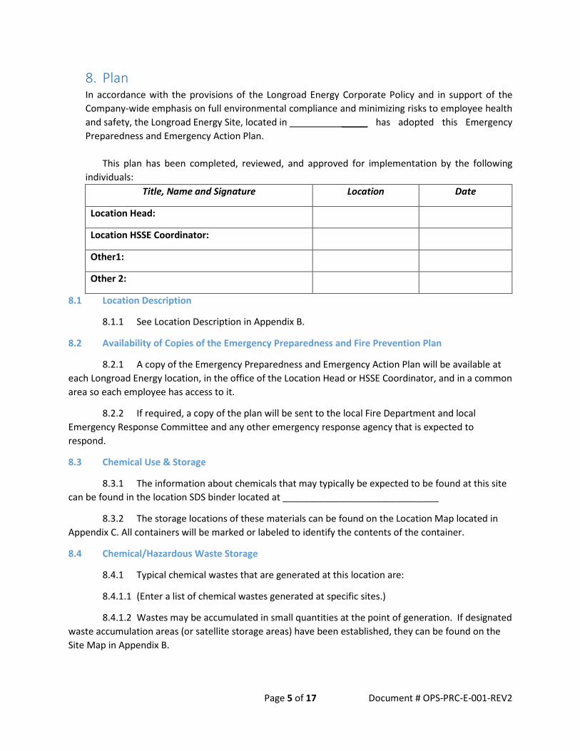
8. Plan In accordance with the provisions of the Longroad Energy Corporate Policy and in support of the Company-wide emphasis on full environmental compliance and minimizing risks to employee health and safety, the Longroad Energy Site, located in _____ has adopted this Emergency Preparedness and Emergency Action Plan.
This plan has been completed, reviewed, and approved for implementation by the following individuals:
Title, Name and Signature Location Date
Location Head:
Location HSSE Coordinator:
Other1:
Other 2:
8.1 Location Description
8.1.1 See Location Description in Appendix B.
8.2 Availability of Copies of the Emergency Preparedness and Fire Prevention Plan
8.2.1 A copy of the Emergency Preparedness and Emergency Action Plan will be available at each Longroad Energy location, in the office of the Location Head or HSSE Coordinator, and in a common area so each employee has access to it.
8.2.2 If required, a copy of the plan will be sent to the local Fire Department and local Emergency Response Committee and any other emergency response agency that is expected to respond.
8.3 Chemical Use & Storage
8.3.1 The information about chemicals that may typically be expected to be found at this site can be found in the location SDS binder located at ______________________________
8.3.2 The storage locations of these materials can be found on the Location Map located in Appendix C. All containers will be marked or labeled to identify the contents of the container.
8.4 Chemical/Hazardous Waste Storage
8.4.1 Typical chemical wastes that are generated at this location are:
8.4.1.1 (Enter a list of chemical wastes generated at specific sites.)
8.4.1.2 Wastes may be accumulated in small quantities at the point of generation. If designated waste accumulation areas (or satellite storage areas) have been established, they can be found on the Site Map in Appendix B.

Page 6 of 17 Document # OPS-PRC-E-001-REV2
8.4.1.3 Wastes are typically accumulated in 200 L (55-gallon) drums that are stored within a secondary containment. As these containers are filled, they are moved to the designated hazardous waste storage area as identified in the Location Map.
8.4.1.4 The chemical and hazardous waste storage areas are inspected regularly to prevent releases, explosions, and fires.
8.5 Potential Emergencies
8.5.1 The Location Head will be designated as the Emergency Coordinator unless otherwise specified in Appendix A. The Location Head will be notified immediately in the event of an emergency. If the emergency is within the capabilities of site personnel, the Emergency Coordinator will coordinate response activities. If the emergency is beyond the capabilities of location personnel, appropriate outside agencies and emergency responders will be notified. These agencies and their corresponding phone numbers are listed in Appendix A.
8.5.2 Emergency actions to be taken for various types of identified emergencies are detailed as follows:
8.6 Fire
8.6.1 Potential for Fire & Safe Operating Procedures
8.6.1.1 Potential ignition sources at this Longroad Energy location are:
(Insert potential ignition sources at your site here)
8.6.1.2 It is required that all fuel and ignition sources (flammable materials) be removed from the location or reduced as much as practically possible.
8.6.1.3 Smoking is only allowed in designated areas as identified in Appendix B.
8.6.1.3.1 It is prohibited to introduce any unnecessary flammable materials/chemicals into the WTG towers. Exceptions will only be made by the HSSE Manager or Location Head.
8.6.1.3.2 Combustible materials such as gearbox oil must be stored in appropriate containers with caps (properly labeled) while being transferred between the top and bottom of the tower.
8.6.2 Control of Fuel Sources
8.6.2.1 All trash must be placed in designated containers.
8.6.2.2 Flammable liquids must be stored in approved containers and placed in flammable liquid storage cabinets when not in use.
8.6.2.3 Accumulations of paper, cardboard, or other highly combustible materials should be kept to a minimum.
8.6.2.4 Areas around fire extinguishers, exits, and electrical panels must be kept clear and unobstructed.

Page 7 of 17 Document # OPS-PRC-E-001-REV2
8.6.2.5 Combustible material should always be stored away from any ignition sources.
8.6.2.6 When transferring flammable liquids from one container to another, always ground and bond the containers to prevent a static electricity spark.
8.6.3 Control of Ignition Sources
8.6.3.1 Do not use equipment that has exposed wiring, cracked or damaged switch plates.
8.6.3.2 Use only approved extension cords for temporary wiring.
8.6.3.3 Never use extension cords in place of permanent wiring.
8.6.3.4 Do not use cords that are damaged or frayed.
8.6.3.5 Do not load motors beyond their capacity.
8.6.3.6 Smoking is allowed in designated areas only and all butts must be disposed of in designated containers.
8.6.3.6.1 Smoking is NOT allowed in the WTG tower, nacelle or hub.
8.6.3.7 If smoke or smoldering is detected from plug powered equipment, disconnect the power supply.
8.6.3.8 When performing welding, cutting or open flame operations outside a designated weld area, a special hot work permit is required (see Longroad Energy HSSE Procedure– Hot Work).
8.6.3.9 Inspections
8.6.3.9.1 The following inspections of Fire Protection Equipment must be completed.
8.6.3.9.2 Automatic Sprinkler System requires annual inspections by a qualified person.
8.6.3.9.3 Emergency Lighting requires monthly inspections – verify that the emergency lighting will engage during an emergency situation.
8.6.3.9.4 Fire Detection Systems require annual inspections – verify that the detection systems will engage in the event of a real emergency. This inspection is usually completed by a detection company.
8.6.3.9.5 Fixed Extinguishing Systems require annual inspections. Ensure all systems are in complete working order.
8.6.3.9.6 Portable Fire Extinguishers in the Locations require monthly inspections– verify all extinguishers have the required charge, are in the correct locations and properly marked.
8.6.3.9.7 Portable Fire Extinguishers also require a periodic maintenance inspection by a qualified person, as well as periodic hydrostatic testing depending on the type of extinguisher.
8.6.4 Response to A Fire
8.6.4.1 Response to a Fire in the Location

Page 8 of 17 Document # OPS-PRC-E-001-REV2
8.6.4.1.1 The first employee discovering a fire shall pull the nearest fire alarm and/or dial the location emergency number as listed in Appendix A. If the employee has the appropriate fire extinguisher training, and the fire is incipient, the employee can try to fight the fire.
8.6.4.1.2 Evacuate the immediate area.
8.6.4.1.3 Notify the Location Head, who will direct the fire department to the proper location.
8.6.4.1.4 The Location Head and designated personnel will ensure the evacuation of personnel has been successfully completed and that all personnel are accounted for.
8.6.4.1.5 People should assemble at the designated Evacuation Meeting Location as described in Appendix B.
8.6.4.1.6 The Location Head will also ensure that equipment is shutdown as necessary.
8.6.4.1.7 The local fire department and the Location Head will determine when normal operations can be resumed.
8.6.4.2 Response to a Fire in an elevated work location
8.6.4.2.1 See SA-010-320-017 Tower Emergency Rescue Procedure
8.6.4.3 Response to a Fire at Substation / Transformer:
8.6.4.3.1 Call the site emergency number immediately. Fire department must be called immediately to contain this type of fire.
8.6.4.3.2 Do not try to extinguish the fire due to high voltage hazards. Cannot use conventional fire extinguishers.
8.6.4.3.3 Report the fire the appropriate utility company.
8.6.4.4 Respond to fire which is out of control
8.6.4.4.1 Barricade hazardous area as applicable.
8.6.5 Fire Drills
8.6.5.1 The location will conduct at least one drill at the beginning of operations. This also enables the local fire department to get a chance to become familiar with our location and be more prepared in the event of an actual emergency. Most fire departments are more than willing to help out with fire drills. Conducting a fire drill involves the following steps:
8.6.5.1.1 Plan the drill.
8.6.5.1.2 Coordinate with the local fire department and fire detection company.
8.6.5.1.3 Conduct the drill.
8.6.5.1.4 Ensure the appropriate evacuation takes place.
8.6.5.1.5 Time the evacuation.

Page 9 of 17 Document # OPS-PRC-E-001-REV2
8.6.5.1.6 Check the site for people who did not leave, areas where the alarm can’t be heard, or other potential problems.
8.6.5.1.7 Give employees the OK to come back inside.
8.6.5.1.8 Critique the drill with the local fire department if they are present.
8.6.5.1.9 Write up a brief report of how the drill went, send a copy to the HSSE Manager and keep it in your site HSSE files.
8.6.6 Emergency Evacuation
8.6.6.1 Evacuation from the Location
8.6.6.1.1 A location evacuation map must be posted in commonly used locations inside the location. (lunch rooms, offices, bathrooms, etc).
8.6.6.1.2 A designated Evacuation Meeting Point must be identified for each location. A Back-Up Evacuation Meeting Point must also be identified in case the primary Evacuation Meeting Point is affected by the emergency (i.e.—wind direction during a fire makes the original Evacuation Meeting Point unusable.)
8.6.6.1.3 All location personnel must receive training of the site’s emergency evacuation procedures within the first week of employment at the Site.
8.6.6.2 During an evacuation the designated Emergency Coordinator shall:
8.6.6.2.1 Keep exits marked, clear and accessible at all times.
8.6.6.2.2 Instruct employees not to try to fight any fire (unless incipient), but simply to report it immediately.
8.6.6.2.3 Notify employees of any evacuation and then verify that all employees are safely at the Evacuation Meeting Point.
8.6.6.2.4 Comply with any instructions from the Fire Department.
8.6.6.2.5 Consult with the Fire Department / HSSE as the situation permits and/or warrants.
8.6.6.2.6 Consult with the Fire Department to determine the extent of any evacuation necessary.
8.6.6.2.7 Supervise any evacuation that is ordered.
8.6.6.2.8 Respond to direction from the Fire Department / HSSE and maintain communication with others.
8.6.6.2.9 Verify that isolated areas are checked for personnel.
8.6.6.2.10 Conduct head count to ensure everyone is accounted for. The designated Emergency Coordinator will notify the fire department if any persons are thought to be inside the building.
Page 10 of 17 Document # OPS-PRC-E-001-REV2
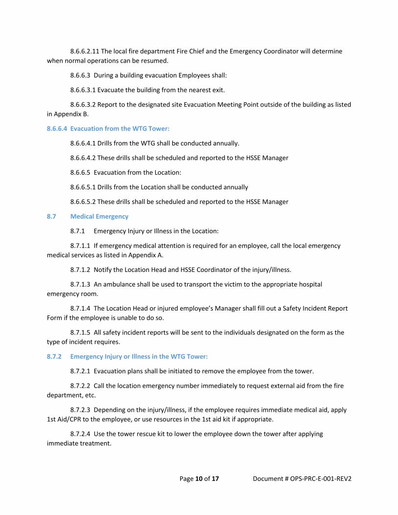
8.6.6.2.11 The local fire department Fire Chief and the Emergency Coordinator will determine when normal operations can be resumed.
8.6.6.3 During a building evacuation Employees shall:
8.6.6.3.1 Evacuate the building from the nearest exit.
8.6.6.3.2 Report to the designated site Evacuation Meeting Point outside of the building as listed in Appendix B.
8.6.6.4 Evacuation from the WTG Tower:
8.6.6.4.1 Drills from the WTG shall be conducted annually.
8.6.6.4.2 These drills shall be scheduled and reported to the HSSE Manager
8.6.6.5 Evacuation from the Location:
8.6.6.5.1 Drills from the Location shall be conducted annually
8.6.6.5.2 These drills shall be scheduled and reported to the HSSE Manager
8.7 Medical Emergency
8.7.1 Emergency Injury or Illness in the Location:
8.7.1.1 If emergency medical attention is required for an employee, call the local emergency medical services as listed in Appendix A.
8.7.1.2 Notify the Location Head and HSSE Coordinator of the injury/illness.
8.7.1.3 An ambulance shall be used to transport the victim to the appropriate hospital emergency room.
8.7.1.4 The Location Head or injured employee’s Manager shall fill out a Safety Incident Report Form if the employee is unable to do so.
8.7.1.5 All safety incident reports will be sent to the individuals designated on the form as the type of incident requires.
8.7.2 Emergency Injury or Illness in the WTG Tower:
8.7.2.1 Evacuation plans shall be initiated to remove the employee from the tower.
8.7.2.2 Call the location emergency number immediately to request external aid from the fire department, etc.
8.7.2.3 Depending on the injury/illness, if the employee requires immediate medical aid, apply 1st Aid/CPR to the employee, or use resources in the 1st aid kit if appropriate.
8.7.2.4 Use the tower rescue kit to lower the employee down the tower after applying immediate treatment.

Page 11 of 17 Document # OPS-PRC-E-001-REV2
8.7.2.5 Wait for emergency medical services to arrive once the injured person is safely on the ground unless transportation by location personnel is required.
8.7.3 Non-emergency Injury or Illness
8.7.3.1 If the employee needs attention by a doctor on a non-emergency basis, the Location Head will ask the employee if he/she wants to see a doctor.
8.7.3.2 The Location Head or HSSE Coordinator will arrange transportation and designate someone to accompany the employee to the doctor.
8.7.3.3 Longroad Energy HSSE Manager must be notified immediately.
8.7.3.4 The Location Head shall fill a Safety Incident Report if the employee is unable.
8.7.3.5 All safety incident reports will be sent to the individuals designated on the form as the type of incident requires.
8.8 Chemical Spill or Leak
8.8.1 Response to a Chemical Spill
8.8.1.1.1 The Location Head should be notified immediately.
8.8.1.1.2 Every effort will be made to prevent spills from entering waterways. Personnel working with chemicals or responding to a spill shall wear proper personal protective equipment, such as safety goggles, gloves, etc.
8.8.1.1.3 Only trained personnel in spill response shall respond to a chemical spill or leak. All others must notify the Location Head immediately.
8.8.1.1.4 For larger spills, additional assistance will be obtained from outside emergency responders or spill cleanup contractors. Spill response materials are kept at the site for small spills. The locations of these spill kits are identified on the Location Map in Appendix B.
8.8.1.2 The primary concerns for responding to chemical spill emergencies are:
8.8.1.2.1 Ensure the safety of all employees.
8.8.1.2.2 Notify appropriate emergency organizations to properly respond to the emergency. (i.e., fire department, ambulance, local/state environmental regulatory authority).
8.8.1.2.3 Get emergency assistance to anyone who has been exposed to the hazardous chemicals.
8.8.1.2.4 Prevent any spills from entering the sanitary and storm sewers.
8.8.1.2.5 Minimize site personnel exposure to the hazardous chemicals by only allowing qualified personnel to respond to the emergency.
8.8.1.2.6 Investigate to determine the cause, effect and damage, if any, and take steps to correct.

Page 12 of 17 Document # OPS-PRC-E-001-REV2
8.8.1.2.7 Arrange for timely cleanup of the chemical spill to minimize the potential of contaminating the environment or further contamination of the site.
8.8.1.3 ISWIM
8.8.1.3.1 Identify the Spill – Identify the material spilling before you attempt to stop, isolate or minimize the spill.
8.8.1.3.2 Stop the Spill—Up-righting a container, closing a valve, or shutting down the equipment.
8.8.1.3.3 Warn others—to stay clear of the area.
8.8.1.3.4 Isolate the spill area—Keep personnel out of the area.
8.8.1.3.5 Minimize exposure and the spread of the spill. Place absorbent materials around the spill to contain its spread. Do not stand in the spilled material while doing this.
8.8.1.4 Response to a Chemical Spill in the WTG
8.8.1.4.1 The Location Head shall be notified immediately.
8.8.1.4.2 Ensure spill absorbent material is available in each service truck and use it to contain the leak.
8.8.1.4.3 If leak cannot be stopped at the turbine by mechanical means, try to contain the leak as much as possible.
8.8.1.4.4 Notify Location Head immediately for guidance in clean-up procedures and regulatory notification.
8.8.1.4.5 Notify a tower cleaning company to clean the outside of the tower if the leak has migrated to the outside of the tower.
8.8.1.4.6 Contain the leak at the bottom of the tower with absorbent material, clay, etc. and put contaminated soil, absorbents in properly labeled containers.
8.8.1.5 Notifications
8.8.1.5.1.1 The Location Head must notify the Spill Release Team should a spill occur that is not controllable by the employees in the immediate area and requires the evacuation of the building. The notification shall include the following information:
8.8.1.5.1.1.1 Amount spilled/leaked,
8.8.1.5.1.1.2 Chemical(s) involved,
8.8.1.5.1.1.3 Time spill/leak occurred, and
8.8.1.5.1.1.4 Where spill/leak occurred.
8.8.1.5.1.1.5 If a spill impacted soil, water, etc.
8.8.1.5.1.1.6 Person responding to spill/leak.

Page 13 of 17 Document # OPS-PRC-E-001-REV2
8.8.1.5.1.2 Should the spill occur and evacuation is necessary, all employees shall immediately evacuate the building to the designated Evacuation Meeting Point.
8.8.1.6 Reportable Quantities
8.8.1.6.1 If a reportable quantity has been released, Longroad Energy will notify the appropriate regulatory agencies, as applicable:
• The National Response Center
• The State Emergency Response Commission
• The Local Emergency Planning Committee
8.8.1.7 Spills that reach the sewer system
8.8.1.7.1 The Location Head shall contact the applicable Sewer District. A detailed written statement describing the causes of the discharge and the measures being taken to prevent future occurrence must follow this notification.
8.9 Earthquake
8.9.1 In the event of an earthquake the following should be done for employees inside of or near structures:
8.9.1.1.1 Take cover, such as under a sturdy piece of furniture, the inside corner of a room or in a close by doorway, to protect yourself from injury.
8.9.1.1.2 If there is overhead glass in the area, cover yourself from falling debris.
8.9.1.1.3 Take a look around for equipment that may fall or tip over in the area and stay clear.
8.9.1.1.4 Do not run from buildings during an earthquake. Most injuries occur outside from flying debris, falling objects or from downed high-voltage wires.
8.9.1.1.5 Extinguish open flames if possible.
8.9.1.1.6 If you are at a location that has an elevator, do not use it during an emergency.
8.9.1.1.7 DO NOT smoke or light a match/lighter.
8.9.1.1.8 Once the initial shock is over, calmly walk out of the building to the Evacuation Meeting Point. Do not reenter the building until the structure has been assessed to be safe.
8.9.1.2 In the event of an earthquake the following should be done for employees outside of and away from structures:
8.9.1.2.1 Stay in the open, away from structures, trees and overhead lines.
8.9.1.2.2 If there are overhead hazards in the area, cover yourself from falling debris.
8.9.1.2.3 DO NOT smoke or light a match/lighter.

Page 14 of 17 Document # OPS-PRC-E-001-REV2
8.9.1.2.4 Once the initial shock is over, calmly walk to the Evacuation Meeting Point. Do not enter buildings until the structure has been assessed to be safe.
8.9.2 Threats of violence
8.9.2.1 The person receiving the call shall:
8.9.2.1.1 Notify the Location Head immediately.
8.9.2.1.2 Listen very carefully, assisted, if possible, by another person who will take careful notes to ensure getting the exact language of the message. Pay special attention to if the caller is a man or a woman, any distinguishing accents, and any background noises that might be heard (children, traffic, etc.).
8.9.2.1.3 See if another person can get the call traced, by contacting the police department, while the caller is kept on the phone.
8.9.2.1.4 Attempt to get the caller to repeat the message several times to elicit further information as to:
8.9.2.1.4.1 Who the caller is
8.9.2.1.4.2 Location of the calling party
8.9.2.1.4.3 What violent action is being planned
8.9.2.1.4.4 Where the action will take place
8.9.2.1.4.5 When it is scheduled to take place
8.9.2.1.4.6 Why Longroad Energy is being targeted with violence
8.9.2.2 The Location Head shall:
8.9.2.2.1 Evacuate the site immediately in the safest possible manner.
8.9.2.2.2 Contact the Police Department listed in Appendix A.
8.9.3 Other Emergencies
8.9.3.1 Power Outage
8.9.3.1.1 Employees should notify the Location Head, if the outage is not immediately apparent.
8.9.3.1.2 The employees involved should take immediate steps to:

Page 15 of 17 Document # OPS-PRC-E-001-REV2
8.9.3.1.2.1 Ensure the safety of personnel.
8.9.3.1.2.2 Restore service.
8.9.3.1.2.3 Investigate to determine cause, effect and damage, if any, and take steps to correct.
8.9.3.1.2.4 If required, call the local utility company. The site-specific utility company is listed in Appendix A.
8.9.3.2 Demonstrations or Civil Disturbances (Including Picketing)
8.9.3.2.1 Any employee seeing evidence of a demonstration within the immediate area of the site shall inform the Location Head
8.9.3.3 Media Requests
8.9.3.3.1 In the event of an HSSE incident that gains media attention, NO ONE at any location shall have any contact with the media unless approved by their manager and External Affairs.
8.10 Training
8.10.1 All Longroad Energy field employees must be trained in the location’s Emergency Preparedness and Emergency Action Plan and Fire Safety Plan.
8.10.2 Where applicable, designated Longroad Energy employees shall be trained on Oil Spill Prevention and the site-specific spill plans, and/or portable fire extinguishers.
8.10.3 Longroad Energy personnel involved with climbing and working in wind turbine must receive training in tower rescue and escape and how to prevent fires while working inside the towers.
8.11 Auditing
8.11.1 Longroad Energy Corporate Safety will review this procedure annually.
8.11 References
8.11.2 Fire Safety Plan
8.12 References
8.11.2 Fire Safety Plan
9. Appendix
9.1Appendix A: Emergency Contact Information LOCATION EMERGENCY CONTACT INFORMATION
Location Name Physical Address
Location Head (Primary) contact info
Name title Office phone email Mobile phone fax

Page 16 of 17 Document # OPS-PRC-E-001-REV2
Location Head (Secondary) contact info
Name title Office phone email Mobile phone fax
HSSE Coordinator contact info
Name title Office phone email Mobile phone fax
Longroad Energy ROC
Primary phone (888) 786-3347 Secondary phone (951) 294-5613
Contractor 1 Primary contact info
Name title Office phone email Mobile phone fax
Contractor 1 Secondary contact info
Name title Office phone email Mobile phone fax
Contractor 2 Primary contact info
Name title Office phone email Mobile phone fax
Contractor 2 Secondary contact info
Name title Office phone email Mobile phone fax
Contractor 3 Primary contact info
Name title Office phone email Mobile phone fax
Contractor 3 Secondary contact info
Name title Office phone email Mobile phone fax
POLICE FIRE EMS Emergency Clinic
Name: Phone Address Fax
Poison Control Name: Phone Spill Response Name: Phone Electric Utility Name: Phone Gas Utility Name: Phone Water Utility Name: Phone
9.2 Appendix B: Location Specific Information The Longroad Energy location at (name and address of location) employs approximately (insert number) people working in (insert number) shifts. The location, a drawing of which is included, encompasses (insert number) square miles. Work at the location includes:
(Provide a description of the type of work performed at the site)

Page 17 of 17 Document # OPS-PRC-E-001-REV2
The site is co-located with ____________________________________. The co-located site performs the following type of work (if applicable):
Location Evacuation Meeting Location: (list)
Alternate Evacuation Meeting Location: (list)
Earthquake Shelter Location: (list)
Fire Protection Equipment Location Specific Fire Detection System(s): Pull Box to Fire Department Automatic to Site Alarm
None
Location Specific Fire Alarm System(s): Manual Activation Automatic Activation None
Location Specific Fire Suppression System(s): Portable ABC Fire Extinguishers Portable CO2 Fire Extinguishers Sprinkler System – Office Sprinkler System – Shop Sprinkler System – Other Emergency Lighting – Office Emergency Lighting – Shop Illuminated Exit Signs None
Portable fire extinguishers, emergency eyewashes, safety showers, emergency first aid kits, and emergency spill response kits are located throughout the site. The location of this equipment is identified on the Location Map.
Insert Location Map as next page and indicate the following:
Waste Accumulation Areas 90-day Storage Areas Spill Kit Locations Chemical Storage Locations Emergency Eyewashes Safety Showers
Portable Fire Extinguishers First Aid Kits Fire Alarms


Exhibit 27-5
Fire Service Response Correspondences


STATE OF MAINE DEPARTMENT OF AGRICULTURE, CONSERVATION & FORESTRY
MAINE FOREST SERVICE 87 AIRPORT ROAD
CENTRAL REGION HQ OLD TOWN, MAINE 04468
DOUG DENICO, DIRECTOR PHONE: (207) 827-1800 OR (207) 827-1804 MAINE FOREST SERVICE FAX: (207) 827-8441 18 ELKINS LANE, HARLOW BUILDING www.maineforestservice.gov
WALTER E. WHITCOMB COMMISSIONER
PAUL R. LEPAGE GOVERNOR
13 September, 2018
Sarah Boucher Gravel, CWB
Stantec
30 Park Drive
Topsham, ME 04086 As the Regional Forest Ranger for the Maine Forest Service, whose Forest Rangers provide wildfire and
limited structure and vehicle fire protection for Maine’s unorganized territories, I can state that the
proposed construction project entitled Weaver Wind Project, should have little impact on my agency’s
ability to quickly respond to emergencies that fall within our purview.
We look forward to hearing more about this project, as well as how we can work together in the areas of
completing response plans and wildfire preparedness activities with all who are involved with the
construction and operation of this project.
Please contact me should you have any questions.
Respectfully, Regional Ranger Jeffrey B. Currier
Maine Forest Service
Central Region Headquarters

Justin Rowell
Eastbrook Volunteer Fire Department
959 Eastbrook Road
Eastbrook, ME. 04634
207-479-8334
09/17/2018
To whom it may concern;
I have reviewed the information and location of the proposed wind project for the town of
Osborn and Eastbrook areas, including the area where the 8 turbines will be installed. At this time, I
believe this project will have minimal or no impact to the fire service. Good communication from the
developer to the key contacts with the towns with maps and information to access the area in case of
emergencies would be key. If there are any further questions please feel free to contact me.
Sincerely,
Justin Rowell
Justin Rowell
Eastbrook Fire Chief
