26 strain gauges - politecnico di milanohome.deib.polimi.it/rech/download/26_strain_gauges.pdf ·...
TRANSCRIPT

Signal Recovery, 2019/2020 – Strain Gauges Ivan Rech
Sensors, Signals and Noise 1
COURSE OUTLINE
• Introduction
• Signals and Noise
• Filtering
• Sensors: Strain Gauges
Signal Recovery, 2019/2020 – Strain Gauges Ivan Rech
Strain Gauges 2
• Stress and strain in elastic materials
• Piezoresistive Effect
• Strain Gauge principle
• Strain Gauge Design and Technology
• Electronics for Measurements and Temperature Compensation
• Measure of bending and composite strain
• Semiconductor Strain Gauges

Signal Recovery, 2019/2020 – Strain Gauges Ivan Rech
Stress and strain in elastic materials
3
Signal Recovery, 2019/2020 – Strain Gauges Ivan Rech
Stress and Strain in Elastic Material 4
LW
H
FF
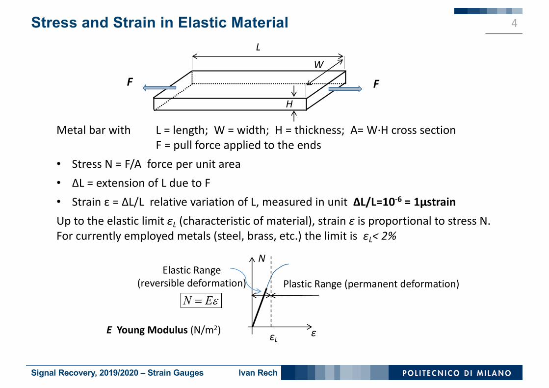
Metal bar with L = length; W = width; H = thickness; A= W·H cross sectionF = pull force applied to the ends
• Stress N = F/A force per unit area• ΔL = extension of L due to F• Strain ε = ΔL/L relative variation of L, measured in unit ΔL/L=10-6 = 1μstrainUp to the elastic limit εL (characteristic of material), strain ε is proportional to stress N. For currently employed metals (steel, brass, etc.) the limit is εL< 2%
N
εεL
Elastic Range(reversible deformation)
N Ee=
E Young Modulus (N/m2)
Plastic Range (permanent deformation)

Signal Recovery, 2019/2020 – Strain Gauges Ivan Rech
Stress and Strain in Elastic Material 5
LW
H
FF
In elastic range, a pull force F causes:1) Extension of L proportional to stress: 𝜀 = ⁄𝑁 𝐸
e.g. for steel E≈ 200·109 N/m2 = 200 GPa (1Pa = 1 Pascal=1N/m2)
2) Contraction of the section dimensions W and H proportional to the L extension 𝜀
For most materials ν ≈ from 0,25 to 0,4; for current metals ν ≈ from 0,3 to 0,35
3) Contraction of the section area A= W·H (in absolute value)
( ) ( )W W H H n e- D = - D = × ν Poisson Ratio (adimensional number)
2A W HA W H
n eD D D» + = ×

Signal Recovery, 2019/2020 – Strain Gauges Ivan Rech
Piezoresistive Effect
6

Signal Recovery, 2019/2020 – Strain Gauges Ivan Rech
Piezoresistive Effect 7
L LRA A
rs
= = R resistance; ρ resistivity; σ = 1/ρ conductivity
• Piezoelectric effect: in various materials a crystal lattice deformation changes the material resistivity, which contributes to the change of macroscopic resistance.
• Strain changes the shape of the energy band curves (energy vs momentum E-k), hence changes the electron effective mass m* and therefore the carrier mobility
• Semiconductors have strong piezoresistive effect and the dependence of conductivity on the strain is markedly nonlinear and strongly dependent on the semiconductor doping and on the temperature
• Metals have small or moderate effect, somewhat higher for Nickel and alloys than other metals. The dependence of conductivity on the strain N is fairly linear and a piezoresistivity coefficient β can be defined
and the relative variation due to the piezoresistive effect can be described as( )1o Nr r b= +
o
N Er b b erD
= = ×

Signal Recovery, 2019/2020 – Strain Gauges Ivan Rech
Strain Gauge principle
8

Signal Recovery, 2019/2020 – Strain Gauges Ivan Rech
Strain Gauge Principle 9
V
L
W
H
FF
I
L LRA A
rs
= = R resistance; ρ resistivity; σ = 1/ρ conductivity
• In principle, a Strain Gauge (SG) is a long and thin metal slab (small cross section H << L and W << L) employed to measure the strain ε along its length L
• It is employed to measure strain in elastic range, without permanent deformation• The relative variation of R is small (small elastic deformation and small or moderate
piezoresistive effect) and can be evaluated in first-order approximation*, i.e. denoting by subscript «o» the quiescent values without strain
( )2 1 2o o o o
R L A E ER L A
r e ne b e e n br
D D D D= - + = + + = + +
* The finite small variation is computed as a differential
Signal Recovery, 2019/2020 – Strain Gauges Ivan Rech
Gauge Factor 10
( )2 1 2o o o o
R L A E ER L A
r e ne b e e n br
D D D D= - + = + + = + +
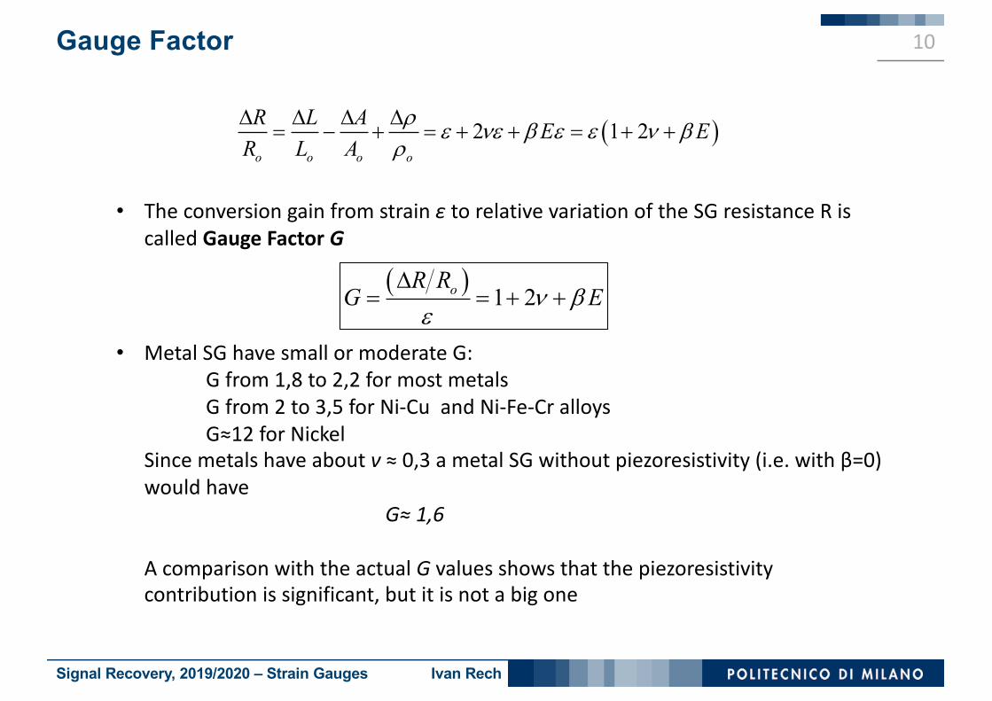
• The conversion gain from strain ε to relative variation of the SG resistance R is called Gauge Factor G
• Metal SG have small or moderate G:G from 1,8 to 2,2 for most metalsG from 2 to 3,5 for Ni-Cu and Ni-Fe-Cr alloysG≈12 for Nickel
Since metals have about ν ≈ 0,3 a metal SG without piezoresistivity (i.e. with β=0) would have
G≈ 1,6
A comparison with the actual G values shows that the piezoresistivity contribution is significant, but it is not a big one
( ) 1 2oR RG En b
eD
= = + +

Signal Recovery, 2019/2020 – Strain Gauges Ivan Rech
Strain Gauge Design and Technology
11

Signal Recovery, 2019/2020 – Strain Gauges Ivan Rech
Design of Strain Gauge Devices 12
Conflicting requirements condition the design and fabrication of SG devicesa) Requirement: SG fastened to the sample under test for having the same strain
Solution: SG fastened onto a robust thin foil, which is then glued to the sampleb) Requirement: SG electrically isolated from the sample under test, for avoiding
shunt effects due to conductive samplesSolution: SG supporting foil in insulating material
c) Requirement: small size of SG, for measuring the local strain and not strain averaged over a fairly wide areaSolution: limited size of the SG foil, as required by the case under test
d) Requirement: not too small resistance of SG, for limiting measurement errors and uncontrolled parasitic effects (electrical contact resistance, etc.):Solution: meander configuration of the resistor, in order to fit a long conductor length into the small area of the foil
Insulating substrate
metal SGSG terminals

Signal Recovery, 2019/2020 – Strain Gauges Ivan Rech
Design of Strain Gauge Devices 13
• Old fashioned wound-wire technology: long thin metal wire wound in meander and fastened on insulating foil; strain measured on Principal Axis x (direction of meander long portions) with Principal Gauge Factor GP
• Main drawbacks: a) sensitive also to strain along Transverse Axis y, though with a minor Transverse Gauge Factor GT ≈ 0,05 GP b) moderate precision and reproducibility; well-matched SG samples are not available
• Modern lithographic technology: exploits lithographic technology (well developed in different scales for printed circuit boards and for integrated circuits) for finely designing SG of small size (1 cm and less) in a very thin metal layer (from 2 to 10 μm) coated over an insulating foil
Principal Axis x
Tran
sver
se
Axis
y
Principal Axis x
Tran
sver
se
Axis
y
WOUND-WIRE SG outline LITHOGRAPHIC SG outline
Signal Recovery, 2019/2020 – Strain Gauges Ivan Rech
Design of Strain Gauge Devices 14
Tran
sver
se
Axis
y
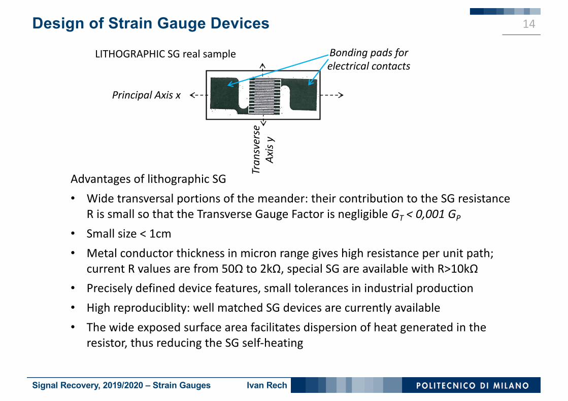
Advantages of lithographic SG• Wide transversal portions of the meander: their contribution to the SG resistance
R is small so that the Transverse Gauge Factor is negligible GT < 0,001 GP
• Small size < 1cm• Metal conductor thickness in micron range gives high resistance per unit path;
current R values are from 50Ω to 2kΩ, special SG are available with R>10kΩ• Precisely defined device features, small tolerances in industrial production• High reproduciblity: well matched SG devices are currently available • The wide exposed surface area facilitates dispersion of heat generated in the
resistor, thus reducing the SG self-heating
Bonding pads for electrical contacts
Principal Axis x
LITHOGRAPHIC SG real sample

Signal Recovery, 2019/2020 – Strain Gauges Ivan Rech
Electronics for Measurementsand
Temperature Compensation
15
Signal Recovery, 2019/2020 – Strain Gauges Ivan Rech
Electronic Measurements with Strain Gauges 16
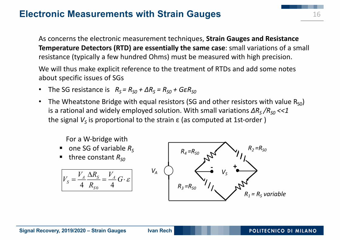
As concerns the electronic measurement techniques, Strain Gauges and Resistance Temperature Detectors (RTD) are essentially the same case: small variations of a small resistance (typically a few hundred Ohms) must be measured with high precision. We will thus make explicit reference to the treatment of RTDs and add some notes about specific issues of SGs• The SG resistance is RS = RS0 + ΔRS = RS0 + GεRS0
• The Wheatstone Bridge with equal resistors (SG and other resistors with value RS0) is a rational and widely employed solution. With small variations ΔRS /RS0 <<1 the signal VS is proportional to the strain ε (as computed at 1st-order )
VSVA
R1 = RS variable
R2 =RS0R4 =RS0
R3 =RS004 4SA A
SS
RV VV GR
eD= = ×
+-
For a W-bridge with§ one SG of variable RS§ three constant RS0
Signal Recovery, 2019/2020 – Strain Gauges Ivan Rech
Temperature Effect in Strain Gauges 17
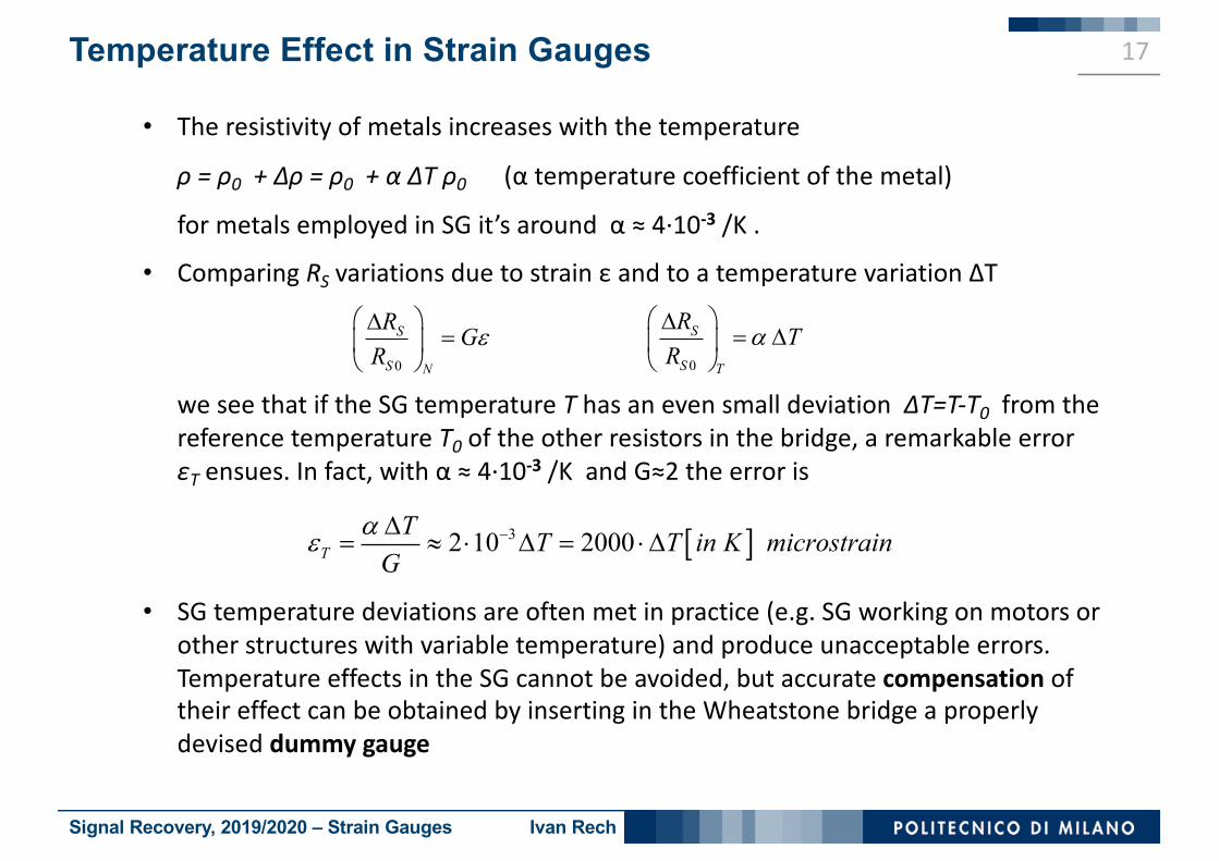
• The resistivity of metals increases with the temperature
ρ = ρ0 + Δρ = ρ0 + α ΔT ρ0 (α temperature coefficient of the metal)
for metals employed in SG it’s around α ≈ 4·10-3 /K .
• Comparing RS variations due to strain ε and to a temperature variation ΔT
we see that if the SG temperature T has an even small deviation ΔT=T-T0 from the reference temperature T0 of the other resistors in the bridge, a remarkable error εT ensues. In fact, with α ≈ 4·10-3 /K and G≈2 the error is
• SG temperature deviations are often met in practice (e.g. SG working on motors or other structures with variable temperature) and produce unacceptable errors. Temperature effects in the SG cannot be avoided, but accurate compensation oftheir effect can be obtained by inserting in the Wheatstone bridge a properly devised dummy gauge
0
S
S T
R TR
aæ öD
= Dç ÷è ø0
S
S N
R GR
eæ öD
=ç ÷è ø
[ ]32 10 2000TT T T in K microstrainG
ae -D= » × D = ×D

Signal Recovery, 2019/2020 – Strain Gauges Ivan Rech
Compensation of Temperature Effects 18
Principal Axis x
Dummy Gauge RDActive Gauge RS
VSVA
0 0D S S STR R T R Ra= + D =
0 0 0 0S S S S ST SR R T R G R R G Ra e e= + D + = +
• Two identical gauges (Active Gauge and Dummy Gauge) are placed on the same foil with principal axes orthogonal
• The foil is glued to the structure under test, with principal axis of the active gauge in the direction of the strain to be measured
• The strain of the structure tested modifies the resistance RS of the active gauge, but not the resistance RD of the dummy gauge
• Active and dummy gauge in close contact with the structure tested are kept at the same temperature of the structure
• The power dissipation in the resistors must be limited by limiting the supply voltage VA , in order to limit the SG self-heating
0S ST SR R G Re= +
D STR R=
R3 =RS0
R4 =RS0
+-
Compensated dual SG outline

Signal Recovery, 2019/2020 – Strain Gauges Ivan Rech
Compensation of Temperature Effects 19
VSVA
• In the bridge configuration shown (active gauge RS inserted in R1 position, dummy gauge RD in R2 position) the effects on the output voltage VS of the temperature variation in RS and RD are compensated, hence VS depends only on the strain ε
• Other alternative configurations of the bridge can be employed for compensation of the temperature effects; e.g. RS inserted in R1 position and RD in R3 position
1 0S ST SR R R G Re= = +
2 D STR R R= =
R3 =RS0
R4 =RS0
Active Gauge terminals
Dummy Gauge terminals
- +
Compensated dual SG real sample

Signal Recovery, 2019/2020 – Strain Gauges Ivan Rech
Measure of bendingand composite strain
20
Signal Recovery, 2019/2020 – Strain Gauges Ivan Rech
Measure of bending and composite strain 21
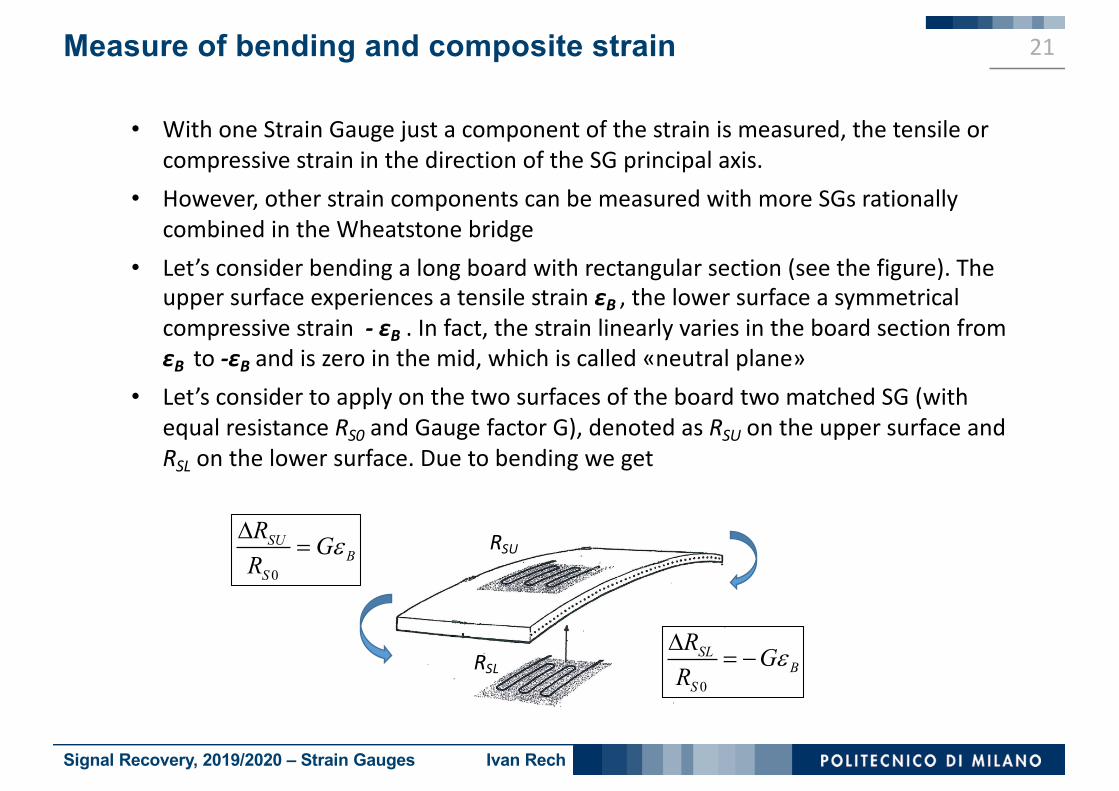
• With one Strain Gauge just a component of the strain is measured, the tensile or compressive strain in the direction of the SG principal axis.
• However, other strain components can be measured with more SGs rationally combined in the Wheatstone bridge
• Let’s consider bending a long board with rectangular section (see the figure). The upper surface experiences a tensile strain εB , the lower surface a symmetrical compressive strain - εB . In fact, the strain linearly varies in the board section from εB to -εB and is zero in the mid, which is called «neutral plane»
• Let’s consider to apply on the two surfaces of the board two matched SG (with equal resistance RS0 and Gauge factor G), denoted as RSU on the upper surface and RSL on the lower surface. Due to bending we get
RSL
RSU
0
SUB
S
R GR
eD=
0
SLB
S
R GR
eD= -

Signal Recovery, 2019/2020 – Strain Gauges Ivan Rech
Measure of bending and composite strain 22
• With RSU inserted in the bridge as R1 and RSL as R3 , we measure the bending strain εB
• Let’s consider now that a compressive force is added at the board ends: equal strain εF is added at the upper and lower surface, but the two SG have equal variation and the added contribution to the bridge output voltage is zero
• In conclusion, by suitably employing two SG we can separately measure the net bending strain εB also in presence of an axial strain εF
VSVA
R1
R2R4
R3
+-
0 04 4 2SU SLA A A
SB BS S
R RV V VV GR R
eD D= - = ×
0 0
SU SLF
S S
R R GR R
eD D= =
0 0
04 4
SU SLA ASF
S S
R RV VVR RD D
= - =2A
S SB SF BVV V V G e= + = ×
RSL
RSU
F
F

Signal Recovery, 2019/2020 – Strain Gauges Ivan Rech
Measure of bending and composite strain 23
• On the other hand, with the same two SG we can also measure separately the net axial strain εF in presence of the bending strain εB
• It is sufficient to change the configuration of the bridge. In fact, with RSU inserted as R1 and RSL as R4 we get
Therefore
VSVA
R1
R2R4
R3
+-
0 04 4 2SU SLA A A
SF FS S
R RV V VV GR R
eD D= + = ×
2A
S SB SF FVV V V G e= + = ×
RSL
RSU
F
F
0 0
04 4
SU SLA ASB
S S
R RV VVR RD D
= + =

Signal Recovery, 2019/2020 – Strain Gauges Ivan Rech
Measure of bending and composite strain 24
RSU
RDU
RSL
RDL
• The measurements of εB and εF obtained with two matched SG as illustrated are correct only if the two SG are at the same temperature, but in many cases this is not achieved because the two SG are not in close proximity
• The drawback is avoided and the approach extended to all cases simply by a) employing dual compensated SGs instead of simple SGs and b) inserting in the bridge each dummy gauge in suitable position to compensate
the associated active gauge
VSVA
R1=RSU
R2=RDUR4=RDL
R3=RSL
+-
• Combinations of various SGs can be employed also for measurements in complex strain situations, i.e. with strain components in various directions, e.g. two-dimensional strain in aeronautical structures, such as aeroplane wings
Signal Recovery, 2019/2020 – Strain Gauges Ivan Rech
Semiconductor Strain Gauges
25

Signal Recovery, 2019/2020 – Strain Gauges Ivan Rech
Semiconductor Strain Gauges 26
• Semiconductors such as Germanium and Silicon have very strong piezoresistive effect. Strain Gauges in such materials thus provide large Gauge Factor G in the range from 100 to 300
• Magnitude and sign of the piezoresistive effect are governed by the type and level of doping. In p-type Silicon the effect is positive (tensile strain increases the resistivity) and in n-type silicon it is negative (tensile strain decreases the resistivity)
• The effect is markedly dependent on the temperature, with G decreasing significanly as the temperature is increased. A typical example is a reduction from G=120 at 10°C to G=105 at 65°C.
• The Gauge Factor G is not constant as the strain is increased, i.e. the gauge is not linear, with G decreasing significantly at moderately high strain. A typical example is a decrease from G=125 at 2000 microstrain down to G=100 at 4000 microstrain
• The elastic range of these semiconductor materials is quite narrower than that of metals, the elastic limit is typically at ≈4000 microstrain

Signal Recovery, 2019/2020 – Strain Gauges Ivan Rech
Semiconductor Strain Gauges 27
In summary, semiconductor SGs suffer noteworthy limitations• Response is not linear• Response is strongly dependent on the temperature• Dynamic range is small but also offer remarkable features, such as• High Gauge Factor, which provides high sensitivity: dynamic strains as small as
0,01microstrains can be measured• Small SG size <1mm, which makes possible to measure highly localized strains,
where a foil metal SG would be too large• Composite structures including various resistors can be fabricated in a small
region of the semiconductor crystal. The monolithic structure ensures equal temperature of the resistors and by selective doping it is possible to obtain different sign of piezoresistive effect in different resistors. Therefore, it is possible to devise SG configurations where the strain effects in different resistors inserted in a Wheatstone bridge collaborate to produce a voltage output, whereas the temperature effects are compensated