2506 polycom ring detector - algo user guide 90... · about the algo 2506 polycom ring detector...
TRANSCRIPT

Document 90-00082C Algo Communication Products Ltd (604) 454-3792 2016-09-29 4500 Beedie St Burnaby BC Canada V5J 5L2 [email protected] Page 1 www.algosolutions.com
2506 Polycom Ring Detector
Wiring & Configuration
Order Codes
2506 Polycom Ring Detector
Document 90-00082C Algo Communication Products Ltd (604) 454-3792 2016-09-29 4500 Beedie St Burnaby BC Canada V5J 5L2 [email protected] Page 2 www.algosolutions.com
Table of Contents
ABOUT THE ALGO 2506 POLYCOM RING DETECTOR .............................................................................. 3
GETTING STARTED - QUICK CONFIGURE & TEST ..................................................................................... 4
8180/8186/8188 WEB INTERFACE CONFIGURATION .............................................................................. 5
8180 WEB CONFIGURATION .................................................................................................................... 6 8186/8188 WEB CONFIGURATION ........................................................................................................... 7
WIRING CONNECTIONS .......................................................................................................................... 8
TRIGGERING MULTIPLE DEVICES .......................................................................................................... 11
TESTING ............................................................................................................................................... 12
TROUBLESHOOTING............................................................................................................................. 12
WIRING CONNECTIONS ......................................................................................................................... 12 HEADSET JACK ..................................................................................................................................... 12 PHONE VOLUME .................................................................................................................................. 12
Document 90-00082C Algo Communication Products Ltd (604) 454-3792 2016-09-29 4500 Beedie St Burnaby BC Canada V5J 5L2 [email protected] Page 3 www.algosolutions.com
About the Algo 2506 Polycom Ring
Detector
Polycom VVX phones can be configured to provide ring audio to the
headset jack instead of the speaker. The Algo 2506 module detects
the low-level audio from the headset jack and provides an isolated
signal to activate an 8128 SIP Strobe Light, 8180 SIP Audio Alerter,
8186 SIP Horn Speaker, or 8188 SIP Ceiling Speaker directly instead
of using SIP.
Only one Algo alerting device (8128, 8180, 8186, or 8188) can be
connected directly to the 2506 Polycom Ring Detector at a time.
However, any of the four devices can relay a signal to additional
devices via the relay output connections on the back or via multicast.
What is Included
2506 Polycom Ring Detector Coiled Handset Cord
Wires
What is not Included 8128 SIP Strobe Light 8180 SIP Audio Alerter 8186 SIP Horn Speaker
8188 SIP Ceiling Speaker
Document 90-00082C Algo Communication Products Ltd (604) 454-3792 2016-09-29 4500 Beedie St Burnaby BC Canada V5J 5L2 [email protected] Page 4 www.algosolutions.com
Getting Started - Quick Configure & Test
This guide provides important safety information which should be
read thoroughly before permanent setup.
1. If using an 8180/8186/8188, first configure the device via the web
interface, as per the instructions in this guide. Next, test that the
configuration is correct by shorting a pair of wires to the input on the
back of the device. (The 8128 does not require any web
configuration.)
2. Connect one end of a wire pair (maximum length of 20 feet) to the
“+” and “-” screw input terminals on the 2506 and the other end to
the relay terminals on the Algo alerting device. The pin polarity and
placement varies between devices. Refer to the guide for more
information.
3. Connect the Algo alerting device to the network via an Ethernet cable
at the back of the device. Ensure that a PoE port is used for power.
4. Set the VVX Polycom phone ringing volume to maximum.
5. Plug one end of the coiled handset cord into the RJ jack on the 2506
and the other end into the HEADSET jack on the Polycom phone.
6. Set the ring signal on the phone to be sent to the headset jack.
7. When an incoming call is received by the Polycom VVX phone, an
audio/visual alert will be triggered.

Document 90-00082C Algo Communication Products Ltd (604) 454-3792 2016-09-29 4500 Beedie St Burnaby BC Canada V5J 5L2 [email protected] Page 5 www.algosolutions.com
8180/8186/8188 Web Interface
Configuration
The Algo 8180, 8186, and 8188 web interface should be configured before any wiring connections are made to avoid damaging the 2506.
The 8128 does not require any web configuration to operate with the 2506.
Connect the Algo audio device to the network via an Ethernet cable at
the back of the device. Ensure that a PoE port is used for power.
After boot up, the device will beep and the intercom will have obtained an IP address. If there is no DHCP server the device will
default to the static IP address 192.168.1.111.
Directions to obtain the IP address of the SIP device can be found in 8180 SIP Audio Alerter User Guide, 8186 SIP Horn Speaker User Guide, or 8188 SIP Ceiling Speaker User Guide. The IP address may
also be discovered by downloading the Algo locator tool to find Algo devices on your network: www.algosolutions.com/locator

Document 90-00082C Algo Communication Products Ltd (604) 454-3792 2016-09-29 4500 Beedie St Burnaby BC Canada V5J 5L2 [email protected] Page 6 www.algosolutions.com
1. Enter the IP address (eg 192.168.1.111) into a browser such as Google Chrome, Firefox, or Internet Explorer (other than IE9).
2. In the web interface, enter the password to log in. The default password is algo.
3. Go to “Advanced Settings > Input/Output” tab.
4. Follow the appropriate instructions below, depending on the
device being used.
5. Click “Save” in the bottom right corner of the page.
6. Short a pair of wires to the input on the back of the device to see
if an alert is triggered. If not, verify the PoE connection and web
configuration options.
8180 Web Configuration
Set the “Speaker Terminal Function” to “Relay Input”.
Ensure that “Relay Input Polarity” is set to “Normally Open
Contact”. Other configuration options can be set as desired.

Document 90-00082C Algo Communication Products Ltd (604) 454-3792 2016-09-29 4500 Beedie St Burnaby BC Canada V5J 5L2 [email protected] Page 7 www.algosolutions.com
8186/8188 Web Configuration
Set the “Relay Input Mode” to “Relay Normally Open”.
Ensure that “Action” is set to “Play Tone”. Other configuration
options can be set as desired.
Document 90-00082C Algo Communication Products Ltd (604) 454-3792 2016-09-29 4500 Beedie St Burnaby BC Canada V5J 5L2 [email protected] Page 8 www.algosolutions.com
Wiring Connections
The 8180/8186/8188 web interface should be configured before any
wiring connections are made to avoid damaging the 2506. The 8128
does not require any web configuration to operate with the 2506.
The 2506 can be connected to an Algo alerting device via the following
setup:
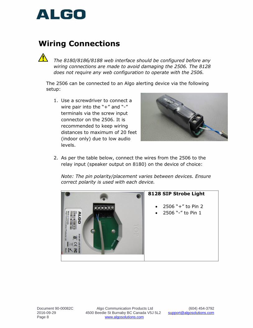
1. Use a screwdriver to connect a
wire pair into the “+” and “-”
terminals via the screw input
connector on the 2506. It is
recommended to keep wiring
distances to maximum of 20 feet
(indoor only) due to low audio
levels.
2. As per the table below, connect the wires from the 2506 to the
relay input (speaker output on 8180) on the device of choice:
Note: The pin polarity/placement varies between devices. Ensure
correct polarity is used with each device.
8128 SIP Strobe Light
2506 “+” to Pin 2
2506 “-” to Pin 1

Document 90-00082C Algo Communication Products Ltd (604) 454-3792 2016-09-29 4500 Beedie St Burnaby BC Canada V5J 5L2 [email protected] Page 9 www.algosolutions.com
8180 SIP Audio Alerter
2506 “+” to Pin 1
2506 “-” to Pin 2
*The speaker output on the
8180 is used as relay input.
8186 SIP Horn Speaker
2506 “+” to Pin 4
2506 “-” to Pin 3
8188 SIP Ceiling Speaker
2506 “+” to Pin 1
2506 “-” to Pin 2
3. Connect the device to the network via an Ethernet cable at the
back of the device. Ensure that a PoE port is used for power.
Document 90-00082C Algo Communication Products Ltd (604) 454-3792 2016-09-29 4500 Beedie St Burnaby BC Canada V5J 5L2 [email protected] Page 10 www.algosolutions.com
4. Set the VVX Polycom phone ringing volume to maximum by
pressing volume up (+) key on the phone, while idle or ringing.
The ring level should appear on the phone’s display screen.
5. Plug the coiled handset cord into the RJ
jack of the 2506.
6. Plug the other end of the handset cord
into the HEADSET jack of the Polycom
VVX phone.
7. Ensure that the ring signal on the
Polycom VVX phone is sent to the
headset jack. On the phone interface
go to:
Settings > Basic > Preferences > Audible Ringer > select Headset
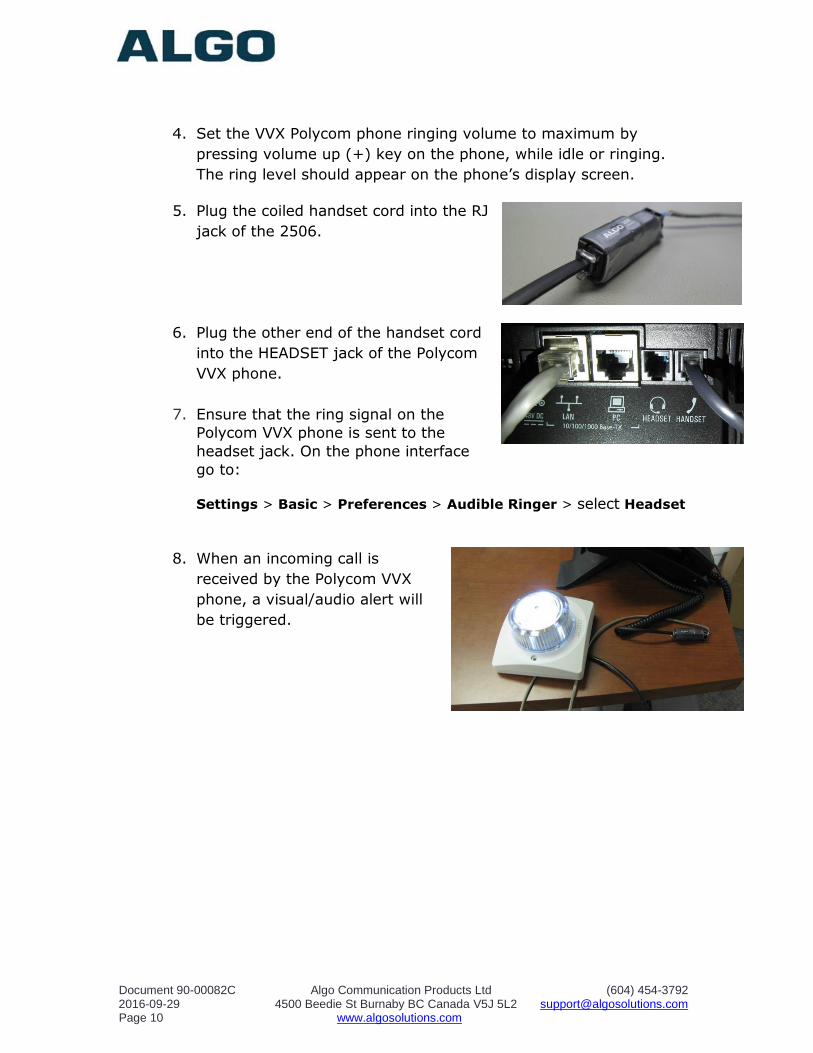
8. When an incoming call is
received by the Polycom VVX
phone, a visual/audio alert will
be triggered.

Document 90-00082C Algo Communication Products Ltd (604) 454-3792 2016-09-29 4500 Beedie St Burnaby BC Canada V5J 5L2 [email protected] Page 11 www.algosolutions.com
Triggering Multiple Devices
Multicast can be used to trigger alerts from one 8128, 8180, 8186, or
8188 device to any number of additional Algo alerting products with
multicast capability (8128, 8180, 8186, 8188, etc). Neither SIP
registration nor SIP licencing will be required. This can be used to
provide both audible and visual alerting, or for coverage of large
areas.
When using multicast, ensure that all the alerting devices are
connected to the same subnet and VLAN. The alerting device that is
connected directly to the 2506 should be set as a multicast master
and all the additional devices as multicast slaves.
For further multicast configuration details, refer to product specific
documentation (8128 SIP Strobe Light User Guide, 8180 SIP Audio
Alerter User Guide, 8186 SIP Horn Speaker User Guide, and 8188 SIP
Ceiling Speaker User Guide).
Non-SIP devices, like the Algo 1128 LED Strobe Light and 1186 Horn
Speaker can also be activated using the relay output on the back of
the 8180/8186/8188 to the relay input on the back of the non-SIP
devices. Thus, once activated, the 8180/8186/8188 will trigger an
additional visual/audio alerts on the 1128/1186.

Document 90-00082C Algo Communication Products Ltd (604) 454-3792 2016-09-29 4500 Beedie St Burnaby BC Canada V5J 5L2 [email protected] Page 12 www.algosolutions.com
Testing
Call the Polycom VVX phone to activate the 8128/8180/8186/8188.
Ensure only one alerting device is connected directly to the 2506 at a
time.
Troubleshooting
Wiring Connections
To verify that the 8128/8180/8186/8188 is powered and configured
correctly, short the wire pair on the input of the alerting device and
see if an audio/visual alert is triggered. If not, verify the PoE
connection and web configuration options (8180/8186/8188 only).
If the 8128/8180/8186/8188 functions correctly, next verify the
polarity of the wiring between the alerting device and the 2506.
If a continuous alert is triggered or the alerting device is activated
when the phone isn’t, the pin polarity may be reversed.
Headset Jack
Ensure that the ring signal is sent to the headset jack on the Polycom
VVX phone. On the phone interface go to:
Settings > Basic > Preferences > Audible Ringer > select Headset
Phone Volume
Ensure that the phone ringer volume is set to a max.