25 9-2014 design and development of micro-controller base differential protection
TRANSCRIPT
DESIGN AND DEVELOPMENT OF MICRO-
CONTROLLER BASE DIFFERENTIAL
PROTECTION SYSTEM OF TRANSFORMER
Prepared by:
Pusprajsinh Zala (120013109008)
Akshar Vaidya (120013109010)
Hitarth Shah (120013109012)
Guided by:
Prof. K.J.Chudasama
Prof. V.S.Sheth
ABSTRACT
The transformers are very costly devices and hence
they required to be protected against any kind of
faults occurring.
Tradionally the protection of transformers has been
relegated to the application of transformer
differential and back up over current relays to
provide short circuit protection.
Micro-controller base Differential protection system
of transformer. Voltage supply done by potential
transformer (step down). Current sampling will be
done by Current transformer.

INTRODUCTION
In this type of protection the rated current flowing
primary side of single phase transformer is
compared with secondary rated current. Figure
shows the micro-controller differential relay
connection diagram.
Differential elements compare an operating current with a restraining current. The operating current also called differential current(Id) can be obtained as the phasor sum of the currents entering the protect element:
Id = I1 + I2. here Id is proportional to the fault current for internal faults and approaches zero for other operating (ideal) conditions.
Hence differential current is given to the micro-controller. Its output signal given to the scanner.

It will scan the data by scan code provided by
microcontroller. This scanning code generates a
signal output for selected parameter. This
parameter will be transferred to microcontroller by
ADC.
Now each channel has its limiting value, when a
channel value goes beyond predefined upper or
lower value, microcontroller detect the error and
operate relative relay and take related step to that
reference and protect the transformer.

PCB DESIGN
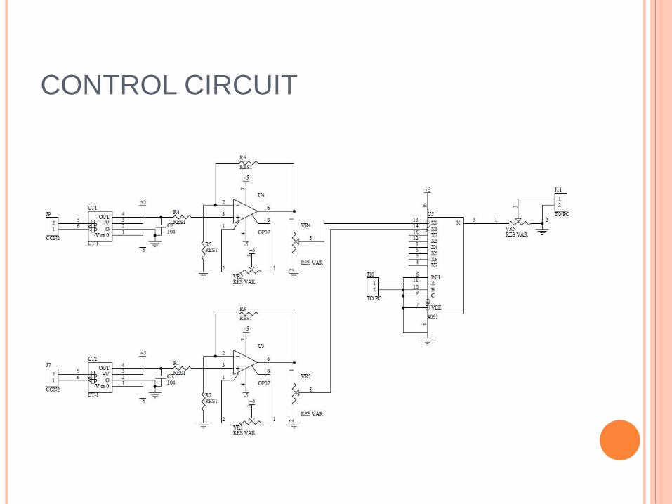
CONTROL CIRCUIT
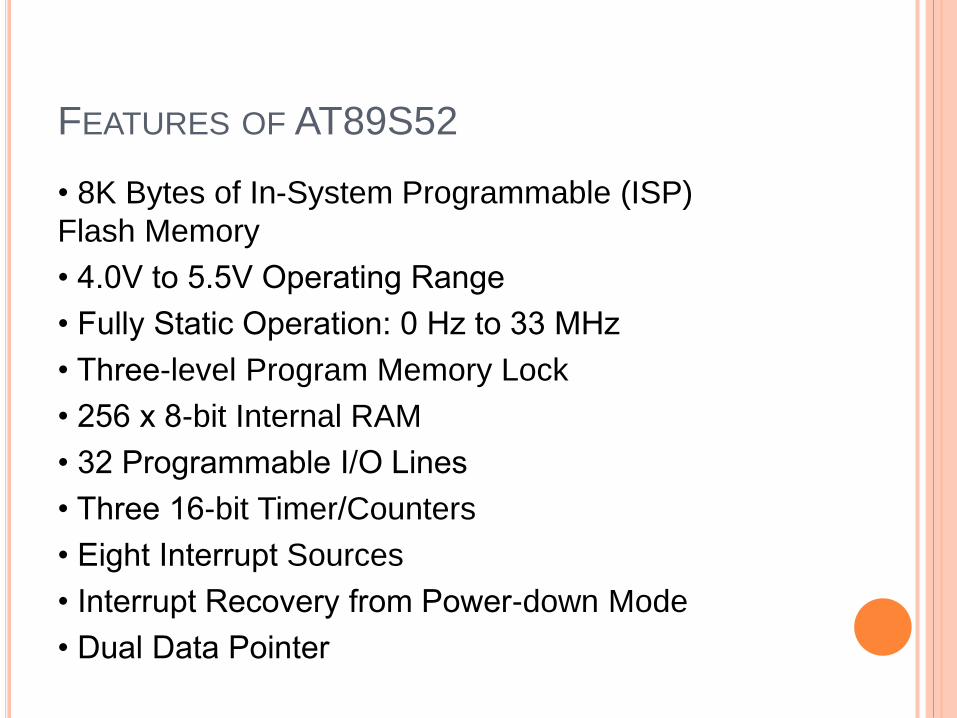
FEATURES OF AT89S52
• 8K Bytes of In-System Programmable (ISP)
Flash Memory
• 4.0V to 5.5V Operating Range
• Fully Static Operation: 0 Hz to 33 MHz
• Three-level Program Memory Lock
• 256 x 8-bit Internal RAM
• 32 Programmable I/O Lines
• Three 16-bit Timer/Counters
• Eight Interrupt Sources
• Interrupt Recovery from Power-down Mode
• Dual Data Pointer
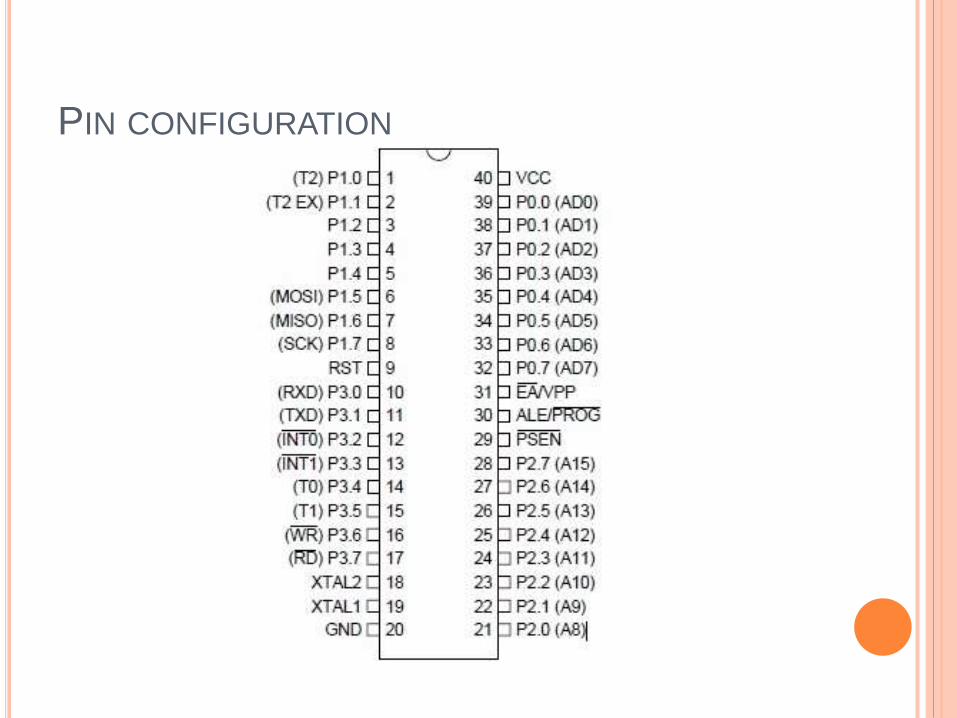
PIN CONFIGURATION
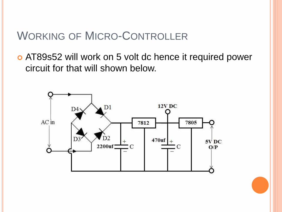
WORKING OF MICRO-CONTROLLER
AT89s52 will work on 5 volt dc hence it required power
circuit for that will shown below.
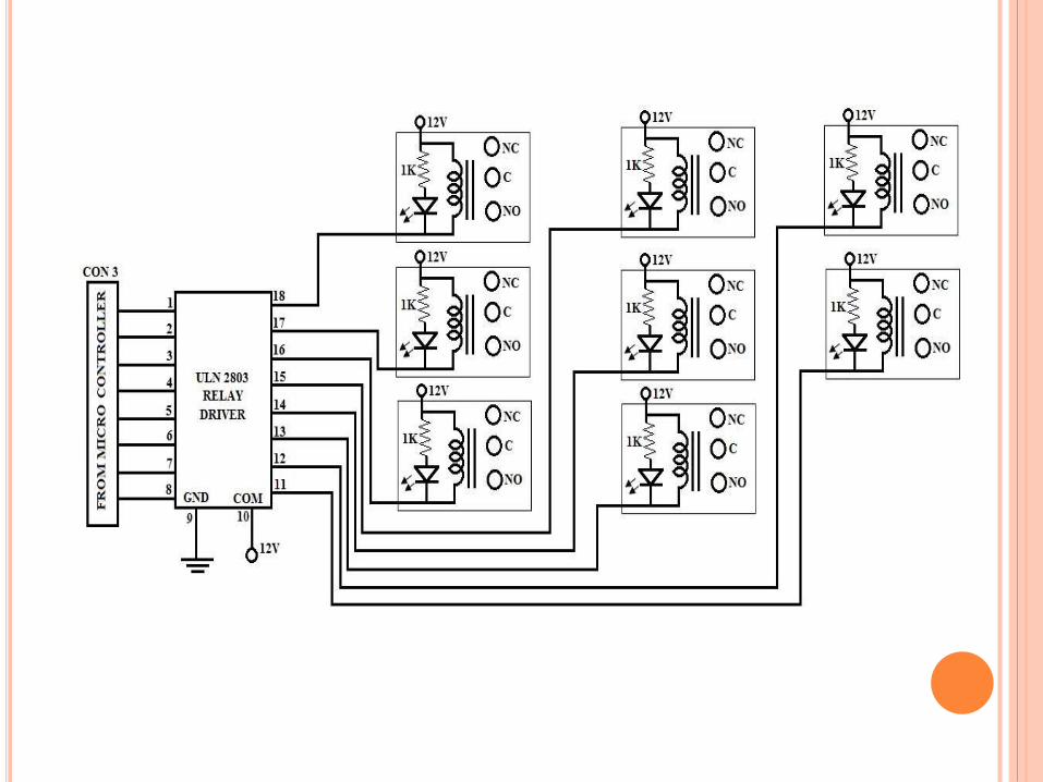
As shown in figure using rectifier, capacitors and voltage regulator IC 7805 it gives the 5 volt dc as a output to the micro-controller and ADC(MPC3201).
ADC signal will collect via different port of micro-controller and it will continuously check with reference signal and great pulse to operate particular relay.
Relay will disconnect the transformer and protect it form the fault. LCD shows which relay is oprated so we can know which fault occur.