2400 series - supplycounter.com
TRANSCRIPT

42 Central Drive | Farmingdale , NY 11735 631-777-5500 | 800-666-4800
www.alphacommunications.comAWD266
Rev. 07/18Made in the USA
Installation & Operations Manual
2400 Series
Items Needed
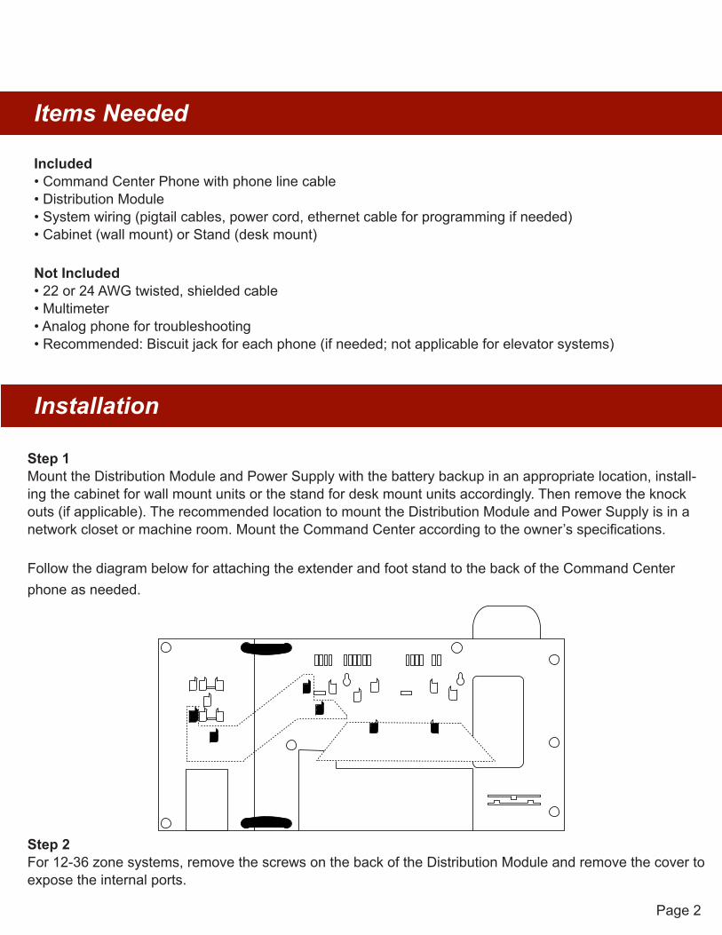
Step 1Mount the Distribution Module and Power Supply with the battery backup in an appropriate location, install-ing the cabinet for wall mount units or the stand for desk mount units accordingly. Then remove the knock outs (if applicable). The recommended location to mount the Distribution Module and Power Supply is in a network closet or machine room. Mount the Command Center according to the owner’s specifications.
Follow the diagram below for attaching the extender and foot stand to the back of the Command Center phone as needed.
Page 2
N56W24720 N. Corporate Circle Sussex, WI 53089 800-451-1460 262-246-4828 (fax)
www.rathmicrotech.com www.area-of-refuge.com
Installation
Included• Command Center Phone with phone line cable• Distribution Module• System wiring (pigtail cables, power cord, ethernet cable for programming if needed)• Cabinet (wall mount) or Stand (desk mount)
Not Included• 22 or 24 AWG twisted, shielded cable• Multimeter• Analog phone for troubleshooting• Recommended: Biscuit jack for each phone (if needed; not applicable for elevator systems)
Step 2For 12-36 zone systems, remove the screws on the back of the Distribution Module and remove the cover to expose the internal ports.
Page 3
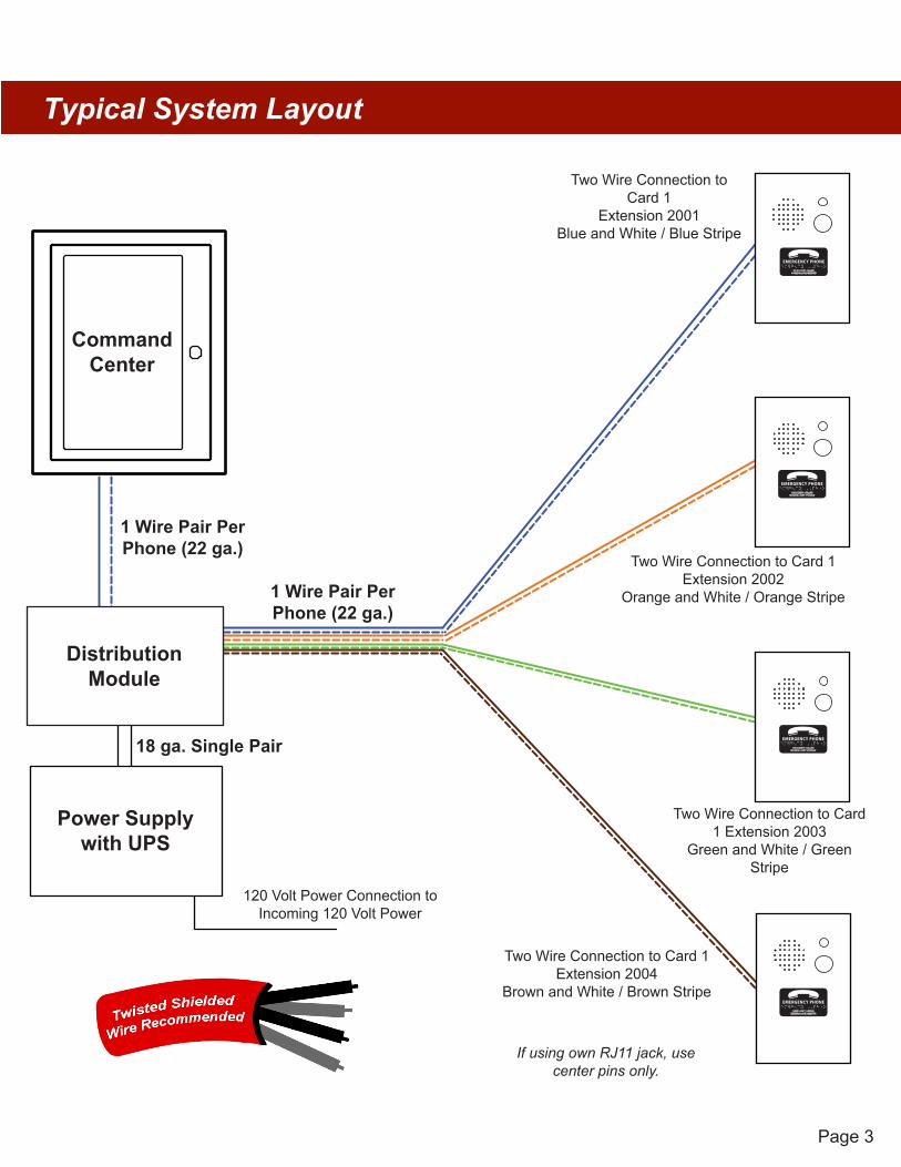
Typical System Layout
CommandCenter
120 Volt Power Connection to Incoming 120 Volt Power
Two Wire Connection to Card 1 Extension 2004
Brown and White / Brown Stripe
Two Wire Connection to Card 1 Extension 2003
Green and White / Green Stripe
Two Wire Connection to Card 1 Extension 2002
Orange and White / Orange Stripe
Two Wire Connection to Card 1
Extension 2001Blue and White / Blue Stripe
N56W24720 N. Corporate Circle Sussex, WI 53089800-451-1460 www.rathcommunications.com
Made in the USA3 Year Warranty
06/18
Command CenterTypical System Layout
If using own RJ11 jack, use center pins only.
1 Wire Pair Per Phone (22 ga.)
18 ga. Single Pair
1 Wire Pair PerPhone (22 ga.)
DistributionModule
Power Supplywith UPS

Page 4
Distribution Module Wiring
Step 3Card Wiring• These instructions apply for connecting the Command Center to the Distribution Module as well as for connecting Emergency Phones to the Distribution Module.• The maximum cable run to the Distribution Module from the base station phone is 6,200’ for 22AWG and 3,900’ for 24AWG cable.• The maximum cable run to an Emergency Phone is 112,500’ for 22AWG and 70,300’ for 24AWG cable.• When connecting Emergency Phones to the Distribution Module, EIA/TIA Standards MUST be followed forwiring the locations to single pair 22AWG or 24AWG UTP twisted, shielded cable.
Note: When using the Command Center for non-elevator applications, it is recommended to use a biscuit jack for connecting each phone. The communication wire pair should be connected to the red and green screw terminals on the biscuit jack. This will prevent loose connections that can cause the system to malfunction.
Option 112-36 Zone System:• On top of each port there is a label indicating connection:
SLT is the port used for connecting emergency phonesDKP is the port used for connecting Command Center phone(s)TWT is the port used for outside Telco line
• Plug the supplied RJ45 pigtail cables into the ports following the wiring chart and pin-out color scheme below
• Refer to the top of the cards to see what type of port and number of extensions• The same pin-out color scheme should be used for the primary card and for all additional cards. Thesystem uses T568-A for pin-out wiring.
• The first card installed will always be:• Port 1: (01-04) Connection for 4 Emergency Phones (SLT)• Port 2: (05-06) Connection for 2 Telco Lines (TWT)• Port 3: (07-08) Connection for up to 2 Command Center Phones (DKP)
Page 5
pg. 6
S01-S04S05-S06
S07-S082011
2012
SLTTW
TDKP
01 - 0405 - 0607 - 08
20132014
20092010
PHONE 9PHONE 10
PHONE 11
PHONE 12
Note: Do not use the green and
brown pairs
PHONE 13
PHONE 14
20162015
PHONE 15
PHONE 16
Card 2 Example
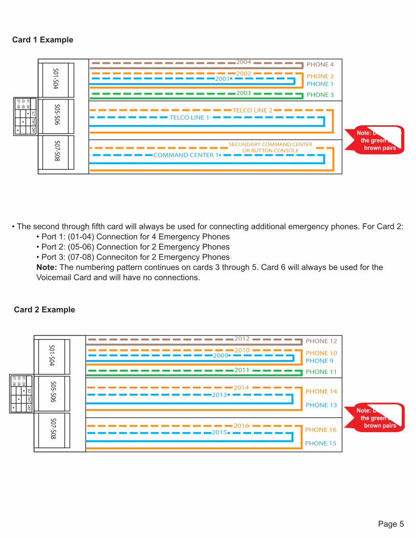
• The second through fifth card will always be used for connecting additional emergency phones. For Card 2:• Port 1: (01-04) Connection for 4 Emergency Phones• Port 2: (05-06) Connection for 2 Emergency Phones• Port 3: (07-08) Conneciton for 2 Emergency PhonesNote: The numbering pattern continues on cards 3 through 5. Card 6 will always be used for theVoicemail Card and will have no connections.
Card 1 Example
pg. 6
S01-S04S05-S06
S07-S08
2003
2004
COMMAND CENTER 1
SLTTW
TDKP
01 - 0405 - 0607 - 08
SECONDARY COMMAND CENTER OR BUTTON CONSOLE
TELCO LINE 1TELCO LINE 2
20012002
PHONE 1PHONE 2
PHONE 3
PHONE 4
Note: Do not use the green and
brown pairs
Page 6
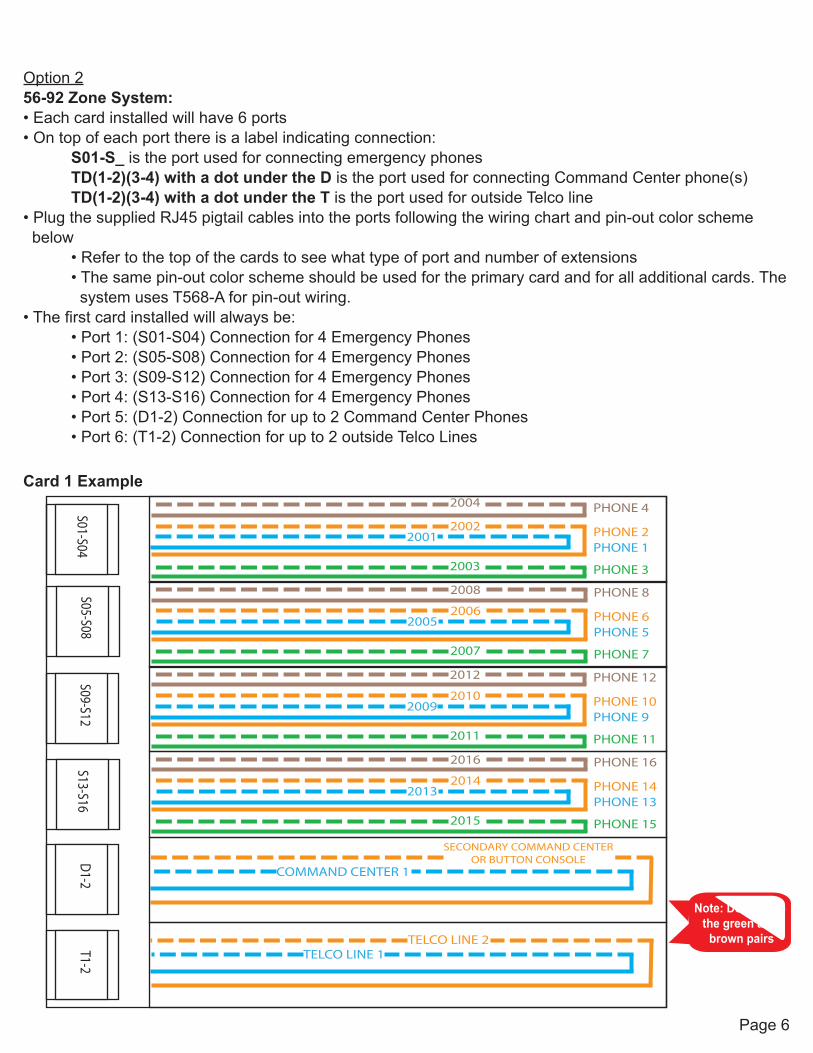
Option 256-92 Zone System:• Each card installed will have 6 ports• On top of each port there is a label indicating connection:
S01-S_ is the port used for connecting emergency phonesTD(1-2)(3-4) with a dot under the D is the port used for connecting Command Center phone(s)TD(1-2)(3-4) with a dot under the T is the port used for outside Telco line
• Plug the supplied RJ45 pigtail cables into the ports following the wiring chart and pin-out color scheme below
• Refer to the top of the cards to see what type of port and number of extensions• The same pin-out color scheme should be used for the primary card and for all additional cards. Thesystem uses T568-A for pin-out wiring.
• The first card installed will always be:• Port 1: (S01-S04) Connection for 4 Emergency Phones• Port 2: (S05-S08) Connection for 4 Emergency Phones• Port 3: (S09-S12) Connection for 4 Emergency Phones• Port 4: (S13-S16) Connection for 4 Emergency Phones• Port 5: (D1-2) Connection for up to 2 Command Center Phones• Port 6: (T1-2) Connection for up to 2 outside Telco Lines
Card 1 Example
pg. 6
S01-S04S05-S08
S09-S12
2003
2004
COMMAND CENTER 1
SECONDARY COMMAND CENTER OR BUTTON CONSOLE
20012002
PHONE 1PHONE 2
PHONE 3
PHONE 4
Note: Do not use the green and
brown pairs
S13-S16D1-2
T1-2
2007
2008
20052006
PHONE 5PHONE 6
PHONE 7
PHONE 8
2011
2012
20092010
PHONE 9PHONE 10
PHONE 11
PHONE 12
2015
2016
20132014
PHONE 13PHONE 14
PHONE 15
PHONE 16
TELCO LINE 1TELCO LINE 2
Page 7
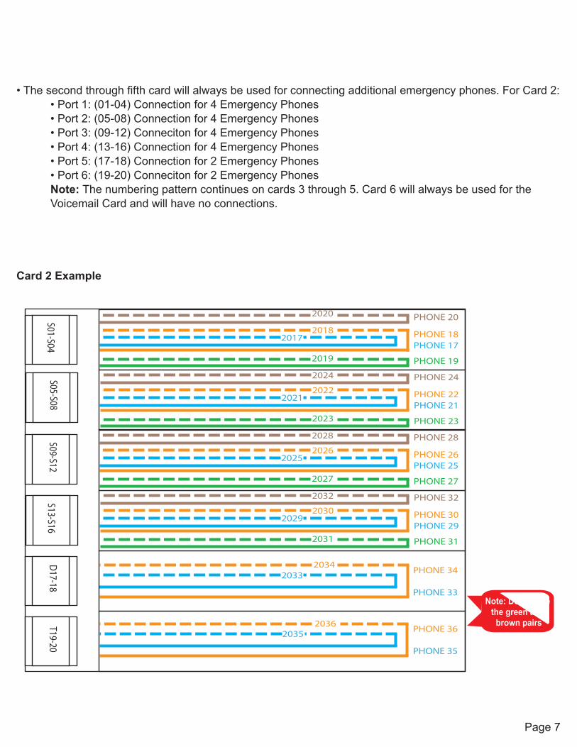
Card 2 Example
• The second through fifth card will always be used for connecting additional emergency phones. For Card 2:• Port 1: (01-04) Connection for 4 Emergency Phones• Port 2: (05-08) Connection for 4 Emergency Phones• Port 3: (09-12) Conneciton for 4 Emergency Phones• Port 4: (13-16) Connection for 4 Emergency Phones• Port 5: (17-18) Connection for 2 Emergency Phones• Port 6: (19-20) Conneciton for 2 Emergency PhonesNote: The numbering pattern continues on cards 3 through 5. Card 6 will always be used for theVoicemail Card and will have no connections.
pg. 6
S01-S04S05-S08
S09-S12
2019
2020
20332034
20172018
PHONE 17PHONE 18
PHONE 19
PHONE 20
Note: Do not use the green and
brown pairs
S13-S16D17-18
T19-20
2023
2024
20212022
PHONE 21PHONE 22
PHONE 23
PHONE 24
2027
2028
20252026
PHONE 25PHONE 26
PHONE 27
PHONE 28
2031
2032
20292030
PHONE 29PHONE 30
PHONE 31
PHONE 32
20352036
PHONE 33
PHONE 34
PHONE 35
PHONE 36
Page 8
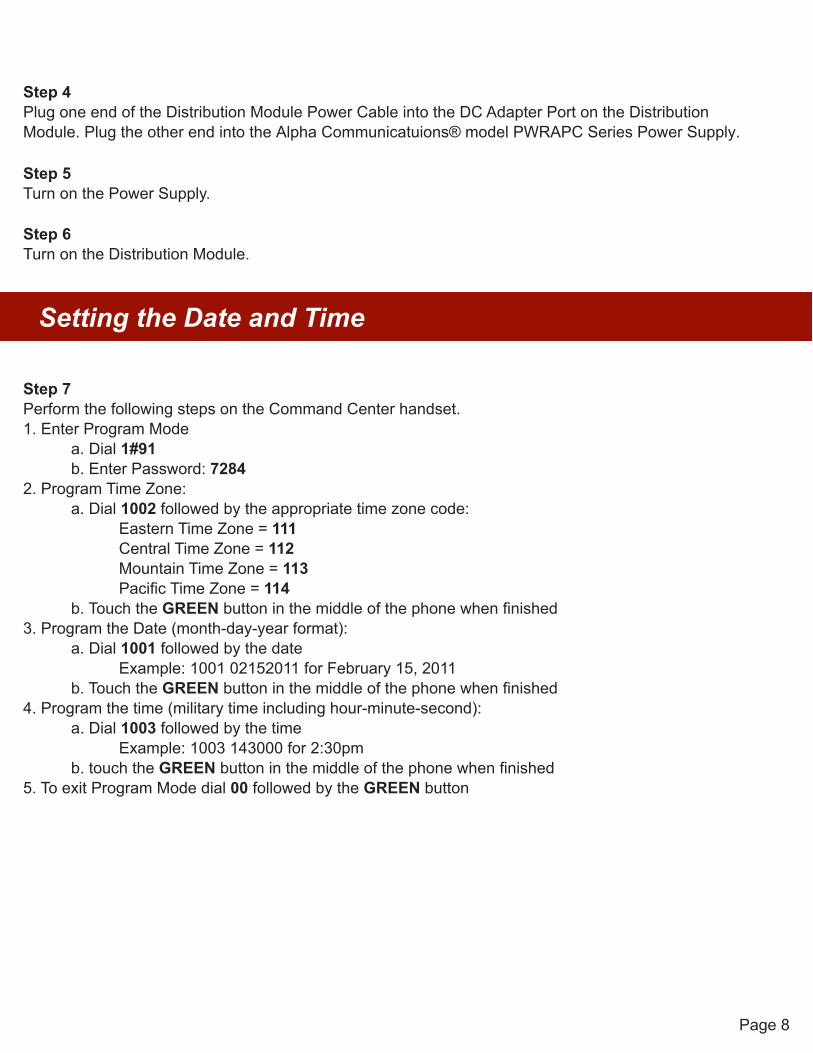
Step 4Plug one end of the Distribution Module Power Cable into the DC Adapter Port on the Distribution Module. Plug the other end into the Alpha Communicatuions® model PWRAPC Series Power Supply.
Step 5Turn on the Power Supply.
Step 6Turn on the Distribution Module.
Setting the Date and Time
Step 7Perform the following steps on the Command Center handset.1. Enter Program Mode
a. Dial 1#91b. Enter Password: 7284
2. Program Time Zone:a. Dial 1002 followed by the appropriate time zone code:
Eastern Time Zone = 111Central Time Zone = 112Mountain Time Zone = 113Pacific Time Zone = 114
b. Touch the GREEN button in the middle of the phone when finished3. Program the Date (month-day-year format):
a. Dial 1001 followed by the dateExample: 1001 02152011 for February 15, 2011
b. Touch the GREEN button in the middle of the phone when finished4. Program the time (military time including hour-minute-second):
a. Dial 1003 followed by the timeExample: 1003 143000 for 2:30pm
b. touch the GREEN button in the middle of the phone when finished5. To exit Program Mode dial 00 followed by the GREEN button
Page 9
Emergency Phone Programming
Step 8Program the emergency phone for the desired calling pattern
Option 1Emergency Phone Calls the Command Center1. For the Emergency Phone to call the Command Center, follow the instructions that came with the phoneto program Memory Location 1 to dial 3931
Option 2Emergency Phone Calls the Command Center First, then a Number Outside the Building1. The Emergency phone can be programmed to call the Command Center first, then if that call is notanswered, call an outside number2. Follow the directions that came with the phone to program Memory Location 1 to dial 39313. Follow the directions below to program the Command Center Phone to dial the external number
a. Press the speaker phone buttonb. Dial 1, 3, 4c. Dial 9, then the external numberd. To exit Program Mode dial 00 followed by the GREEN button
Step 9Program the location message for the emergency phone. This is an optional feature. Skip this step if a location message is not desired.
Option 12100 Series Phone1. Follow the instructions that came with the phone to set the message frequency to option 32. Record your message
a. At the end of the message add “For two-way communication, press * at any time”
Option 22400 Series Phone1. Follow the instructions that came with the phone to set the message frequency to option 32. Record your message
a. At the end of the message add “For two-way communication, press # four times after thebeep”
Page 10
Operating Instructions
Indicator Status1. Red LED Light - Incoming call or connected to outside party2. Blue LED Light - Active call3. Blue LED Flashing - Call on hold
Answering Call at Command Center1. Lift the handset to answer the first incoming call2. If multiple calls are coming in, press the red LED light next to the desired call (this will place the originalcall on hold)
Disconnecting Calls:1. Select the desired flashing blue LED and press the *, # buttons2. Each call must be disconnected individuallyNote: If you hang up the handset before disconnecting each call, the LED(s) will remain illuminated. Lift the handset, press the illuminated LED, the number 5 button, then *, #. To disconnect, hang up the handset. Repeat for each illuminated LED.
Joining a Call Already in Progress1. Pick up the handset, press the red LED, then the number 5 button2. You will be in a 3-way conversation with the outside party and location
Calling a Location1. Pick up the handset and press the button for the desired location

Page 11
Troubleshooting
Problem Possible Cause & SolutionsCommand Center will not power on:
• Check wires for voltage. It should be 28vdc• If no voltage is detected, confirm you are connected to the DKP porton the Distribution Module
• If you have 48vdc, you are incorrectly connected to an SLT port
Emergency Phones will not call out:
• Check wires for voltage. It should be 48vdc• If no voltage is detected, confirm you are connected to the SLT porton the Distribution Module. Note: some SLT ports only use the blueand orange pairs
• If you have 28vdc, you are incorrectly connected to the DKP port• Make sure you dial any access digit that may be required to dial outof your building
Phone will make internal calls, but not external calls:
• Check the phone line is connected to the correct port on theDistribution Module
• Verify the phone line by making sure it has 48-52vdc on the line anduse an analog phone to verify you are able to call in and out
Insufficient volume on call boxes:
• To adjust the volume on SmartPhones, turn the VR1 port• To adjust the volume on 2400 Phones, use the VOL key
Lights continuously blink on button for call box:
• The phone is not properly hung up. Lift the Command Centerhandset, select the blinking light, then hang up the handset
Lights periodically blink on Command Center:
• This indicates the phone is doing a phone line check. This is anormal function of the system and no action is needed
• To disable this function, refer to the SmartPhone Programming Guide