235 diesel operator and parts manual - tennant …...about this manual b 235 mm331 (3-93) the...
TRANSCRIPT

235D
MM331
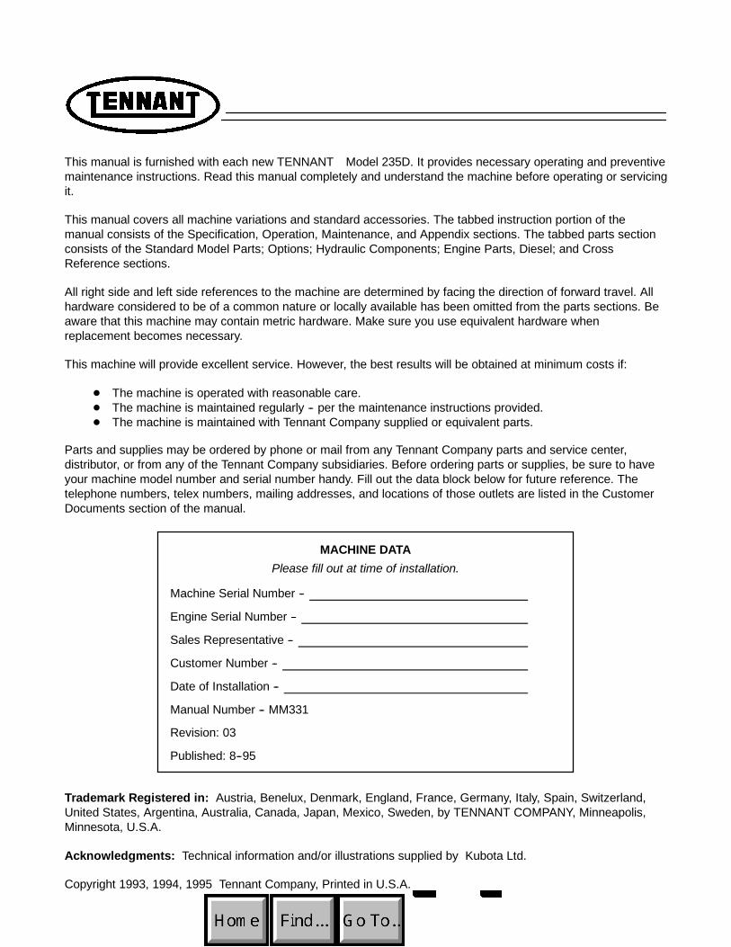
This manual is furnished with each new TENNANT Model 235D. It provides necessary operating and preventivemaintenance instructions. Read this manual completely and understand the machine before operating or servicingit.
This manual covers all machine variations and standard accessories. The tabbed instruction portion of themanual consists of the Specification, Operation, Maintenance, and Appendix sections. The tabbed parts sectionconsists of the Standard Model Parts; Options; Hydraulic Components; Engine Parts, Diesel; and CrossReference sections.
All right side and left side references to the machine are determined by facing the direction of forward travel. Allhardware considered to be of a common nature or locally available has been omitted from the parts sections. Beaware that this machine may contain metric hardware. Make sure you use equivalent hardware whenreplacement becomes necessary.
This machine will provide excellent service. However, the best results will be obtained at minimum costs if:
D The machine is operated with reasonable care.D The machine is maintained regularly -- per the maintenance instructions provided.D The machine is maintained with Tennant Company supplied or equivalent parts.
Parts and supplies may be ordered by phone or mail from any Tennant Company parts and service center,distributor, or from any of the Tennant Company subsidiaries. Before ordering parts or supplies, be sure to haveyour machine model number and serial number handy. Fill out the data block below for future reference. Thetelephone numbers, telex numbers, mailing addresses, and locations of those outlets are listed in the CustomerDocuments section of the manual.
MACHINE DATAPlease fill out at time of installation.
Machine Serial Number --
Engine Serial Number --
Sales Representative --
Customer Number --
Date of Installation --
Manual Number -- MM331
Revision: 03
Published: 8--95
Trademark Registered in: Austria, Benelux, Denmark, England, France, Germany, Italy, Spain, Switzerland,United States, Argentina, Australia, Canada, Japan, Mexico, Sweden, by TENNANT COMPANY, Minneapolis,Minnesota, U.S.A.
Acknowledgments: Technical information and/or illustrations supplied by Kubota Ltd.
Copyright 1993, 1994, 1995 Tennant Company, Printed in U.S.A.

ABOUT THIS MANUAL
a235 MM331 (3--93)
ABOUT THIS MANUAL
The machine manual that you received with yourTENNANT machine contains valuable informationabout the operation and maintenance, andnumerous sections filled with TENNANT partnumbers for the repair of the machine. Pleaseread through this section titled ABOUT THISMANUAL to become familiar with the contents ofthe machine manual, making the information youare looking for easier to find.
The machine manual consists of several sectionsof reference information, and the remaindercontain part number information for orderingrepair parts for the machine. Each section has ashaded bar at the top of the page with the nameof that section. Just as this section has the titleABOUT THIS MANUAL on the top of each page.This way you can tell which section you are in atall times.
REFERENCE SECTIONSThe reference information sections of the manualare; General Information, Specifications,Operation, Maintenance, and Appendix.
GENERAL INFORMATION -- The GeneralInformation section of the manual contains thesafety precautions, the location of the safetylabels on the machine, and a table of contents ofthe entire manual. The Safety Precautions are anoverview of the safety measures to be observedwhen operating and maintaining your machine.The location of the safety labels show themounting location of the safety labels for use inthe replacement of the labels. The table ofcontents in this section is a list of all the table ofcontents that appear in the front of each section inthe manual. This can be used for easy referenceto locate information in a particular section of themanual.
SPECIFICATIONS -- The Specifications section ofthe manual contains machine specificationinformation useful in the operation andmaintenance of the machine. This section givesyou specification information on the engine,electric motors, brake system, hydraulics, fluidcapacities, and machine weight to mention a few.The section also has a illustration of the top andside view of the machine with the height and widthdimensions displayed.
OPERATION -- The Operation section of themanual contains information needed to operatethe machine. This section will list the controls andinstruments on the machine, overview themachine operation, and tell you how to transportand store the machine.
MAINTENANCE -- The Maintenance sectioncontains information on the suggestedmaintenance procedures and adjustments to keepyour machine in top operating condition. Thesection includes a Maintenance Chart listing themaintenance schedule and the areas of themachine to be addressed. Each subject ofmaintenance is covered in more detail in suchareas as Lubrication, Hydraulics, Engine, andElectrical System.
APPENDIX -- The Appendix contains hardwareand hydraulic information. Standard hardwaretorques and identification information is included,plus hydraulic torques if your machine ishydraulically controlled.
PART SECTIONSThe remaining sections of the manual contain partnumber information for ordering repair parts foryour machine. The manual contains part numberinformation on every type of machine modelavailable in the model size of your particularmachine. Therefore there will be part numberinformation in your manual you will not need torefer to when wanting to place an order.
The main thing you need to know about yourmachine is what type of model is it. Is themachine powered by an engine or batteries? If themachine has an engine, is it fueled from gasoline,LPG, or diesel? If it is a mid-sized or largersweeper, is it multi-level or low dump? For thescrubbers, is it SRSror standard. Determiningthis information about your machine will helpguide you through the separate parts sections tofind the repair part you need.

ABOUT THIS MANUAL
235 MM331 (3--93)b
The smaller line of sweeper and scrubbers haveless complicated part section arrangement, andare easier to find your way through the partssections. The larger machines can have quite avariety of model types which significantlyincreases the size to the machine manual.Because of this, on the larger machine we madethe first part section, Section 5, a part sectionwhich contains parts common to all type of themachine. If the machine has an engine, thissection contains parts information on a gasolinepowered machine.
The remaining sections contain only partsinformation which is unique to that particularmachine type, such as unique diesel parts on themachine, or unique SRSrparts. Knowing themachine model type you have is important whensearching for that part information you need forordering repair parts. Start in that unique sectionfirst when looking for a part, then go to the firstparts section, Section 5, if the part can’t be foundin the unique section.
MACHINE SERIAL NUMBERSWhen a design change takes place to a machine,the changes are indicated in the parts sectionswith machine serial numbers. Know the serialnumber of your machine which can be found onthe machine data plate mounted on the machine.Record this number on the inside front cover ofyour manual along with your customer number.
Machine number usage is recorded in theMachine Serial Number column of the parts listsin the parts sections of the manual. If the machineserial number column lists zeros on the left side ofthe dash, then this part is used on all machines;such as (000000-- ).
If the column lists zeros on the left of the dashand a number on the right of the dash, then thepart is used on machines up to and including thatmachine serial number; such as (00000--002345).
For parts that are used on machines beginning atand continuing on from a certain serial number,the column would list a serial number on the left ofthe dash and have blank spaces on the right sideof the dash; such as (002346-- ). This partwould be used on machines starting with thatmachine serial number and greater.
Finally, parts can be used on machines with serialnumbers in a certain block of numbers. In thissituation there is a serial number on the left andright side of the dash. The part is then used on amachine with a serial number starting at thenumber on the left and up to and including thenumber on the right; such as (002346--008900).
PARTS ASSEMBLIESA part assembly has parts within the assembly,such as a parking brake consisting of othersmaller parts. What parts are contained in a partassembly can be determined by an indentationarrangement in the description column of theparts lists.
Here is an example of a part assembly, in thiscase we will use the parking brake mentionedpreviously:
MachineSerial Number Description Qty.(000000-- ) Parking Brake 1(000000-- ) Pin, Roll 1(000000-- ) Link 1(000000-- ) Spring, Compression 1(000000-- ) Pin, Roll 1(000000-- ) Support 1(000000-- ) Lever, Release 1(000000-- ) Rod, Parking Brake 1(000000-- ) Washer, 0.50” 3
In this example, the parts whose descriptions areindented under the parking brake are all parts ofthe parking brake. When you order the parkingbrake you will receive all the parts listed under it.You also can order any of the individual partslisted under the parking brake if it is the only partyou need.

ABOUT THIS MANUAL
c235 MM331 (3--93)
SUPPLIER COMPONENT BREAKDOWNSTENNANT purchases certain components of themachine from suppliers. Some of thesecomponents are engines, hydraulic pumps andmotors, electric motors, and solution pumps.
For those purchased components that arerepairable, lists of parts for them appear in thelater part of the parts sections. These are thesupplier breakdowns. The engine breakdowncontains both supplier and TENNANT partsnumbers for repair parts. Breakdowns forhydraulic and electrical components haveTENNANT part numbers for the parts TENNANTsupplies. The serial numbers listed in any of theparts lists in these sections is a serial number themanufacturer uses to identify design changes intheir particular component.
ORDERING REPAIR PARTSOnce you have located a part to order, there areseveral things you need to have to place theorder. At the beginning of each parts section is anOrdering Repair Parts page which lists theinformation you will need to place your order.Review this list before placing the order.
ABOUT THIS MANUAL
235 MM331 (3--93)d
GENERAL INFORMATION
i235 MM331 (3--93)
SAFETY PRECAUTIONS
The following symbols are used throughout thismanual as indicated in their descriptions:
WARNING: To warn of hazards orunsafe practices which could result in
severe personal injury or death.
FOR SAFETY: To identify actions which mustbe followed for safe operation of equipment.
The following information signals potentiallydangerous conditions to the operator orequipment. Read this manual carefully. Knowwhen these conditions can exist. Locate all safetydevices on the machine. Then, take necessarysteps to train machine operating personnel.Report machine damage or faulty operationimmediately. Do not use the machine if it is not inproper operating condition.
FOR SAFETY:
1. Do Not Operate Machine:-- Unless Trained And Authorized.-- Unless Operation Manual Is Read And
Understood.-- In Flammable Or Explosive Areas
Unless Designed For Use In ThoseAreas.
-- In Areas With Possible Falling ObjectsUnless Equipped With OverheadGuard.
2. Before Starting Machine:-- Check For Fuel Leaks.-- Keep Sparks And Open Flame Away
From Refueling Area.-- Make Sure All Safety Devices Are In
Place And Operate Properly.-- Check Brakes And Steering For Proper
Operation.
3. When Starting Machine:-- Keep Foot On Brake And Directional
Pedal In Neutral.
4. When Using Machine:-- Use Brakes To Stop Machine.-- Go Slow On Grades And Slippery
Surfaces.-- Use Care When Backing Machine.-- Move Machine With Care When
Hopper Is Raised.-- Make Sure Adequate Clearance Is
Available Before Raising Hopper.-- Do Not Carry Riders On Machine.-- Always Follow Safety And Traffic
Rules.
5. Before Leaving Or Servicing Machine:-- Stop On Level Surface.-- Set Parking Brake.-- Turn Off Machine And Remove Key.
6. When Servicing Machine:-- Avoid Moving Parts. Do Not Wear
Loose Jackets, Shirts, Or SleevesWhen Working On Machine.
-- Block Machine Tires Before JackingMachine Up.
-- Jack Machine Up At DesignatedLocations Only. Block Machine UpWith Jack Stands.
-- Use Hoist Or Jack Of AdequateCapacity To Lift Machine.
-- Wear Eye And Ear Protection WhenUsing Pressurized Air Or Water.
-- Disconnect Battery ConnectionsBefore Working On Machine.
-- Avoid Contact With Battery Acid.-- Avoid Contact With Hot Engine
Coolant.-- Allow Engine To Cool.-- Keep Flames And Sparks Away From
Fuel System Service Area. Keep AreaWell Ventilated.
-- Use Cardboard To Locate LeakingHydraulic Fluid Under Pressure.
-- Use TENNANT Supplied Or EquivalentReplacement Parts.
WARNING: Engine Emits Toxic Gases.Severe Respiratory Damage Or
Asphyxiation Can Result. Provide AdequateVentilation. Consult With Your RegulatoryAgency For Exposure Limits. Keep EngineProperly Tuned.
WARNING: Machine Can Emit ExcessiveNoise. Consult With Your Regulatory
Agency For Exposure Limits. Hearing LossCan Result. Wear Hearing Protection.
WARNING: Lift Arm Pinch Point. StayClear Of Hopper Lift Arms.
WARNING: Raised Hopper May Fall.Engage Hopper Support Bar.
WARNING: Moving Belt. Keep Away.

GENERAL INFORMATION
235 MM331 (3--93)ii
The following safety labels are mounted on themachine in the locations indicated. If these, orany, labels become damaged or illegible, install anew label in its place.
03403
FOR SAFETY THERMO SENTRYt LABEL --LOCATED ON THE LIFT ARM CROSSMEMBER.
03402
FOR SAFETY LABEL -- LOCATED ON THESIDE OF THE CONTROL PANEL.
03486

GENERAL INFORMATION
iii235 MM331 (3--93)
03398
HOPPER SUPPORT BAR WARNING LABEL --LOCATED ON THE OPERATOR SIDE OFHOPPER LIFT ARM.
03397
FAN BELT DRIVE WARNING LABEL --LOCATED ON THE VACUUM FAN.
03401
HOPPER LIFT ARM PINCH POINT CAUTIONLABEL (2) -- LOCATED ON THE HOPPER LIFTARMS.
03399
FALLING HOPPER WARNING LABEL --LOCATED ON THE FRONT OF THE BRUSHWRAP.
03486

GENERAL INFORMATION
235 MM331 (8--95)iv
CONTENTS
PageGENERAL INFORMATION i. . . . . . . . . . . . . .
SAFETY PRECAUTIONS i. . . . . . . . . . . .
SPECIFICATIONS 1-1. . . . . . . . . . . . . . . . . . . . .MACHINE SPECIFICATIONS 1-3. . . . . . . . .
POWER TYPE 1-3. . . . . . . . . . . . . . . . . . .POWER TRAIN 1-3. . . . . . . . . . . . . . . . . .STEERING 1-3. . . . . . . . . . . . . . . . . . . . . .HYDRAULIC SYSTEM 1-3. . . . . . . . . . . .BRAKING SYSTEM 1-3. . . . . . . . . . . . . .SUSPENSION SYSTEM 1-3. . . . . . . . . .SYSTEM FLUID CAPACITIES 1-4. . . . .GENERAL MACHINE DIMENSIONS --
CAPACITIES 1-4. . . . . . . . . . . . . . .MACHINE WEIGHTS 1-4. . . . . . . . . . . . .
MACHINE DIMENSIONS 1-5. . . . . . . . . . . . .
OPERATION 2-1. . . . . . . . . . . . . . . . . . . . . . . . . .PREPARATION FOR OPERATION 2-3. . . .
AFTER UNCRATING AND BEFOREOPERATING MACHINE: 2-3. . . . . . .
OPERATION OF CONTROLS 2-4. . . . . . . .MACHINE COMPONENTS 2-4. . . . . . . .CONTROLS AND INSTRUMENTS 2-5.BRAKE PEDAL 2-6. . . . . . . . . . . . . . . . . .DIRECTIONAL PEDAL 2-6. . . . . . . . . . . .PARKING BRAKE LEVER 2-6. . . . . . . . .OPERATOR SEAT 2-6. . . . . . . . . . . . . . . .ADJUSTABLE SEAT LEVER (OPTION) 2-6SEAT SUPPORT LEVER 2-6. . . . . . . . . .SIDE BRUSH AND HOPPER LEVER 2-6THROTTLE LEVER 2-6. . . . . . . . . . . . . . .TEMP LIGHT 2-6. . . . . . . . . . . . . . . . . . . .AMPS LIGHT 2-6. . . . . . . . . . . . . . . . . . . .OIL PRESSURE LIGHT 2-7. . . . . . . . . . .HOPPER DOOR SWITCH 2-7. . . . . . . . .LIGHT SWITCH 2-7. . . . . . . . . . . . . . . . . .KEY-OPERATED IGNITION SWITCH 2-7MAIN BRUSH LEVER 2-7. . . . . . . . . . . . .GLOW PLUG INDICATOR 2-7. . . . . . . . .VACUUM LEVER 2-7. . . . . . . . . . . . . . . . .HOUR METER 2-7. . . . . . . . . . . . . . . . . . .FUEL LEVEL GAUGE 2-7. . . . . . . . . . . . .FLASHER SWITCH 2-7. . . . . . . . . . . . . . .STEERING WHEEL 2-7. . . . . . . . . . . . . .HORN BUTTON 2-7. . . . . . . . . . . . . . . . . .SIDE BRUSH LEVER 2-8. . . . . . . . . . . . .SIDE BRUSH ADJUSTMENT KNOB 2-8AUXILIARY SIDE BRUSH
IN-OUT SWITCH (OPTION) 2-8. . . .AUXILIARY SIDE BRUSH
UP-DOWN SWITCH (OPTION) 2-8. .CIRCUIT BREAKERS 2-9. . . . . . . . . . . . .HOPPER SUPPORT BAR 2-9. . . . . . . . .
PageMACHINE OPERATION 2-10. . . . . . . . . . . . . .
NORMAL SWEEPING OPERATION 2-10PRE-START CHECKLIST 2-10. . . . . . .TO START MACHINE 2-10. . . . . . . . . .TO SWEEP 2-11. . . . . . . . . . . . . . . . . . .TO DUMP HOPPER 2-11. . . . . . . . . . .POST OPERATION CHECKLIST --
ENGINE OPERATING 2-11. . . .TO STOP MACHINE 2-12. . . . . . . . . . .POST OPERATION CHECKLIST --
ENGINE STOPPED 2-12. . . . . .TO ENGAGE HOPPER
SUPPORT BAR 2-12. . . . . . . . . . . .TO DISENGAGE HOPPER
SUPPORT BAR 2-13. . . . . . . . . . . . .OPERATION ON GRADES 2-13. . . . . . . .MACHINE TROUBLESHOOTING 2-14. .
TRANSPORTING MACHINE 2-15. . . . . . . . . .PUSHING OR TOWING MACHINE 2-15.MACHINE JACKING 2-15. . . . . . . . . . . . . .
TO JACK UP MACHINE 2-15. . . . . . . .MACHINE TIE-DOWNS 2-16. . . . . . . . . . .
MACHINE STORAGE 2-17. . . . . . . . . . . . . . . .STORING MACHINE 2-17. . . . . . . . . . . . .
MAINTENANCE 3-1. . . . . . . . . . . . . . . . . . . . . . .RECOMMENDED FIRST 50-HOUR
MACHINE INSPECTION 3-3. . . . . . . . . .MAINTENANCE CHART 3-4. . . . . . . . . . . . .LUBRICATION 3-6. . . . . . . . . . . . . . . . . . . . . .
ENGINE 3-6. . . . . . . . . . . . . . . . . . . . . . . . .SIDE BRUSH LEVER PIVOT 3-6. . . . . .REAR WHEEL SUPPORT BEARING 3-7STEERING LINKAGE 3-7. . . . . . . . . . . . .
HYDRAULICS 3-8. . . . . . . . . . . . . . . . . . . . . .HYDRAULIC FLUID 3-8. . . . . . . . . . . . . .HYDRAULIC FLUID RESERVOIR 3-8. .HYDRAULIC FILTER 3-8. . . . . . . . . . . . .
TO REPLACE FILTER ELEMENT 3-9HYDRAULIC PUMPS 3-9. . . . . . . . . . . . .
TO START AND BREAK-INHYDRAULIC PUMP 3-9. . . . . . . . .
DIRECTIONAL PEDAL 3-10. . . . . . . . . . . .TO ADJUST DIRECTIONAL
PEDAL LINKAGE 3-10. . . . . . . . . . .LIFT ARM SPEED LIMITER 3-11. . . . . . .HYDRAULIC FLUID LEAKS 3-12. . . . . . .HYDRAULIC SCHEMATIC 3-13. . . . . . . . .HYDRAULIC SYSTEM
TROUBLESHOOTING 3-14. . . . . . . . .HYDRAULIC COMPONENTS
TROUBLESHOOTING 3-15. . . . . . . . .

GENERAL INFORMATION
v235 MM331 (8--95)
PageENGINE 3-16. . . . . . . . . . . . . . . . . . . . . . . . . . .
ENGINE LUBRICATION 3-16. . . . . . . . . . .COOLING SYSTEM 3-16. . . . . . . . . . . . . .AIR INTAKE SYSTEM 3-17. . . . . . . . . . . .AIR FILTER 3-18. . . . . . . . . . . . . . . . . . . . . .
TO REPLACE AIRFILTER ELEMENT 3-18. . . . . . . . . .
FUEL SYSTEM 3-19. . . . . . . . . . . . . . . . . .FUEL SYSTEM 3-19. . . . . . . . . . . . . . . .FUEL WATER TRAP FILTER 3-19. . . .TO REPLACE FUEL
FILTER ELEMENT 3-19. . . . . . . . . .PRIMING FUEL SYSTEM 3-20. . . . . .TO PRIME FUEL SYSTEM 3-20. . . . .
DIESEL FUEL TROUBLESHOOTING 3-21CYLINDER HEAD 3-22. . . . . . . . . . . . . . . .
CYLINDER HEAD 3-22. . . . . . . . . . . . .VALVE CLEARANCE 3-22. . . . . . . . . . .DECOMPRESSION LEVER 3-22. . . . .
ELECTRICAL SYSTEM 3-23. . . . . . . . . . . . . .BATTERY 3-23. . . . . . . . . . . . . . . . . . . . . . .ELECTRICAL SCHEMATIC 3-24. . . . . . . .ELECTRICAL SCHEMATIC,
AUXILIARY SIDE BRUSH 3-25. . . . . .BELTS AND CHAINS 3-26. . . . . . . . . . . . . . . .
HYDRAULIC PUMP BELT 3-26. . . . . . . . .TO REPLACE AND ADJUST
HYDRAULIC PUMP BELT 3-26. . . .VACUUM FAN BELT 3-26. . . . . . . . . . . . . .
TO REPLACE AND ADJUSTVACUUM FAN BELT 3-26. . . . . . . .
MAIN BRUSH BELT 3-28. . . . . . . . . . . . . .TO REPLACE MAIN
BRUSH BELT 3-28. . . . . . . . . . . . . .FAN BELT 3-28. . . . . . . . . . . . . . . . . . . . . . .
TO REPLACE AND ADJUSTFAN BELT 3-28. . . . . . . . . . . . . . . . .
TAPER LOCK BUSHINGS 3-30. . . . . . . . .TO REMOVE TAPER
LOCK BUSHING 3-30. . . . . . . . . . .TO INSTALL TAPER
LOCK BUSHING 3-30. . . . . . . . . . .STATIC DRAG CHAIN 3-30. . . . . . . . . . . .
DEBRIS HOPPER AND DUST FILTER 3-31.DEBRIS HOPPER 3-31. . . . . . . . . . . . . . . .TO CHECK AND ADJUST HOPPER
FLOOR CLEARANCE 3-31. . . . . . . . . .THERMO SENTRYt 3-31. . . . . . . . . . . . .
TO CHECK THETHERMO SENTRYt 3-31. . . . . . . .
HOPPER DUST FILTER 3-32. . . . . . . . . . .TO REMOVE AND REPLACE
HOPPER DUST FILTER 3-33. . . . . . . .
PageBRUSHES 3-34. . . . . . . . . . . . . . . . . . . . . . . . . .
MAIN BRUSH 3-34. . . . . . . . . . . . . . . . . . . .TO REMOVE MAIN BRUSH 3-34. . . .TO INSTALL MAIN BRUSH 3-34. . . . .TO CHECK AND ADJUST MAIN
BRUSH PATTERN 3-34. . . . . . . . . .SIDE BRUSH 3-36. . . . . . . . . . . . . . . . . . . .
TO REMOVE SIDE BRUSH 3-36. . . . .TO INSTALL SIDE BRUSH 3-36. . . . .
SKIRTS AND SEALS 3-37. . . . . . . . . . . . . . . .BRUSH SKIRTS 3-37. . . . . . . . . . . . . . . . . .
TO REPLACE AND ADJUSTBRUSH SKIRTS 3-37. . . . . . . . . . . .
REAR SKIRTS 3-37. . . . . . . . . . . . . . . . . . .TO REPLACE AND ADJUST
REAR SKIRTS 3-37. . . . . . . . . . . . .HOPPER LIP SKIRT 3-38. . . . . . . . . . . . . .
TO REPLACE HOPPERLIP SKIRT 3-38. . . . . . . . . . . . . . . . .
DUST SEALS 3-38. . . . . . . . . . . . . . . . . . . .TO REPLACE DUST SEALS 3-38. . . .
HOPPER DUMP DOOR SEAL 3-39. . . . .TO REPLACE HOPPER DUMP
DOOR SEAL 3-39. . . . . . . . . . . . . . .VACUUM FAN SEAL 3-40. . . . . . . . . . . . . .FILTER COVER SEAL 3-40. . . . . . . . . . . .
BRAKES AND TIRES 3-41. . . . . . . . . . . . . . . .BRAKES 3-41. . . . . . . . . . . . . . . . . . . . . . . .TIRES 3-41. . . . . . . . . . . . . . . . . . . . . . . . . . .REAR WHEEL 3-41. . . . . . . . . . . . . . . . . . . .
APPENDIX 4-1. . . . . . . . . . . . . . . . . . . . . . . . . . . .HARDWARE INFORMATION 4-3. . . . . . . . .
STANDARD BOLT TORQUE CHART 4-3METRIC BOLT TORQUE CHART 4-3. .BOLT IDENTIFICATION 4-3. . . . . . . . . . .THREAD SEALANT AND LOCKING
COMPOUNDS 4-3. . . . . . . . . . . . . . . .HYDRAULIC FITTING INFORMATION 4-4.
HYDRAULIC TAPERED PIPE FITTING(NPT) TORQUE CHART 4-4. . . . . . . .
HYDRAULIC TAPERED SEAT FITTING(JIC) TORQUE CHART 4-4. . . . . . . . .
HYDRAULIC O--RING FITTING TORQUECHART 4-4. . . . . . . . . . . . . . . . . . . . . . .
GENERAL INFORMATION
235 MM331 (3--94)vi
PageSTANDARD MODEL PARTS 5-1. . . . . . . . . . . .
ORDERING REPAIR PARTS 5-3. . . . . . . . .Fig. 1 -- Recommended General
Maintenance Items 5-4. . . . . . .Fig. 2 -- Replacement Brushes 5-5. . . . . . . .Fig. 3 -- Main Frame Group 5-6. . . . . . . . . . .Fig. 4 -- Seat and Shrouds Group 5-8. . . . .Fig. 5 -- Front Wheel and Brake Group 5-10.Fig. 6 -- Hopper Lift Arms Group 5-12. . . . . .Fig. 7 -- Hopper Middle and Cover Group 5-14Fig. 8 -- Hopper Bottom Group 5-16. . . . . . . .Fig. 9 -- Hopper Headlights and
Access Door Group 5-18. . . . . .Fig. 10 -- Hopper Filter and Shaker
Motor Group 5-19. . . . . . . . . . . . .Fig. 11 -- Hopper Dump Door and
Actuator Group 5-20. . . . . . . . . . . . .Fig. 12 -- Vacuum Fan Control Group 5-22. . .Fig. 13 -- Vacuum Fan Assembly 5-24. . . . . .Fig. 14 -- Main Brush Drive Group 5-26. . . . .Fig. 15 -- Main Brush Idler Group 5-28. . . . . .Fig. 16 -- Side Brush Group 5-30. . . . . . . . . . .Fig. 17 -- Hydraulic Lift Cylinder and
Filter Group 5-32. . . . . . . . . . . . .Fig. 18 -- Pump Group 5-34. . . . . . . . . . . . . . . .Fig. 19 -- Control Valve and Throttle Group . . .5-36Fig. 20 -- Hydraulic Reservoir Group 5-38. . .Fig. 21 -- Rear Drive Wheel Group 5-39. . . . .Fig. 22 -- Hydraulic Hoses Group 5-40. . . . . .Fig. 23 -- Steering Wheel Group 5-42. . . . . . .Fig. 24 -- Directional Pedal Group 5-44. . . . . .Fig. 25 -- Speed Limiter Group 5-45. . . . . . . .Fig. 26 -- Engine Group 5-46. . . . . . . . . . . . . . .Fig. 27 -- Fuel Tank and Fuel Line Group 5-48Fig. 28 -- Control Panel Group 5-50. . . . . . . . .Fig. 29 -- Wire Harness Group 5-52. . . . . . . . .Fig. 30 -- Labels Group 5-54. . . . . . . . . . . . . . .
OPTIONS 6-1. . . . . . . . . . . . . . . . . . . . . . . . . . . . .ORDERING REPAIR PARTS 6-3. . . . . . . . .Fig. 1 -- Cab Kit 6-4. . . . . . . . . . . . . . . . . . . . .Fig. 2 -- Overhead Guard Kit 6-5. . . . . . . . . .Fig. 3 -- Revolving Light Kit,
Overhead Guard 6-6. . . . . . . . . . . .Fig. 4 -- Revolving Light Kit, Shroud 6-7. . . .Fig. 5 -- Demo Kit 6-8. . . . . . . . . . . . . . . . . . . .Fig. 6 -- Foam Filled Tire Kit 6-8. . . . . . . . .Fig. 7 -- Adjustable Seat Kit 6-9. . . . . . . . . . .Fig. 8 -- Oil Drain Kit 6-10. . . . . . . . . . . . . . . . .Fig. 9 -- Auxiliary Side Brush
Electrical Group 6-11. . . . . . . . . .Fig. 10 -- Auxiliary Side Brush Group 6-12. . .Fig. 11 -- Auxiliary Side Brush
Hydraulic Hose Group 6-14. . . .
PageHYDRAULIC COMPONENTS 7-1. . . . . . . . . . . .
ORDERING REPAIR PARTS 7-3. . . . . . . . .Fig. 1 -- Hydraulic Motor
Breakdown, 87417 7-4. . . . . . .Fig. 2 -- Hydraulic Motor
Breakdown, 87475 7-5. . . . . . .Fig. 3 -- Hydraulic Valve
Breakdown, 87409 7-6. . . . . . .Fig. 4 -- Hydraulic Pump
Breakdown, 87734 7-7. . . . . . .Fig. 5 -- Hydraulic Lift Cylinder
Breakdown, 87055 7-8. . . . . . .Fig. 6 -- Hydraulic Lift Cylinder
Breakdown, 48575 7-9. . . . . . .Fig. 7 -- Hydraulic Lift Cylinder Breakdown,
65223 7-10. . . . . . . . . . . . . . . . . .Fig. 8 -- Hydraulic Pump Breakdown,
87451 7-11. . . . . . . . . . . . . . . . . .Fig. 9 -- Hydraulic Motor Breakdown,
28804 7-12. . . . . . . . . . . . . . . . . .
ENGINE PARTS, DIESEL 8-1. . . . . . . . . . . . . . .ORDERING REPAIR PARTS 8-3. . . . . . . . .Fig. 1 -- Crankcase Group 8-4. . . . . . . . . . . .Fig. 2 -- Gear Case Group 8-6. . . . . . . . . . . .Fig. 3 -- Cylinder Head Group 8-8. . . . . . . . .Fig. 4 -- Bearing Case Group 8-9. . . . . . . . .Fig. 5 -- Breather Group 8-10. . . . . . . . . . . . . .Fig. 6 -- Air Cleaner and Manifolds Group 8-12Fig. 7 -- Valve, Rocker Arm Group 8-14. . . . .Fig. 8 -- Head Cover Group 8-15. . . . . . . . . . .Fig. 9 -- Camshaft Group 8-16. . . . . . . . . . . . .Fig. 10 -- Piston, Crankshaft Group 8-18. . . .Fig. 11 -- Flywheel Group 8-20. . . . . . . . . . . . .Fig. 12 -- Injection Pump Group 8-21. . . . . . . .Fig. 13 -- Governor Group 8-22. . . . . . . . . . . .Fig. 14 -- Radiator Group 8-24. . . . . . . . . . . . .
CROSS REFERENCE 9-1. . . . . . . . . . . . . . . . . .PART NUMBER TO PAGE NUMBER CROSS
REFERENCE LIST 9-3. . . . . . . . . . . .
SPECIFICATIONS
1-1235 MM331 (3--93)
SECTION 1CONTENTS
PageMACHINE SPECIFICATIONS 1-3. . . . . . . . . . . .
POWER TYPE 1-3. . . . . . . . . . . . . . . . . . . . . .POWER TRAIN 1-3. . . . . . . . . . . . . . . . . . . . .STEERING 1-3. . . . . . . . . . . . . . . . . . . . . . . . .HYDRAULIC SYSTEM 1-3. . . . . . . . . . . . . . .BRAKING SYSTEM 1-3. . . . . . . . . . . . . . . . .SUSPENSION SYSTEM 1-3. . . . . . . . . . . . .SYSTEM FLUID CAPACITIES 1-4. . . . . . . .GENERAL MACHINE DIMENSIONS --
CAPACITIES 1-4. . . . . . . . . . . . . . . . . . . . .MACHINE WEIGHTS 1-4. . . . . . . . . . . . . . . .
MACHINE DIMENSIONS 1-5. . . . . . . . . . . . . . . .
SPECIFICATIONS
235 MM331 (3--93)1-2
SPECIFICATIONS
1-3235 MM331 (3--93)
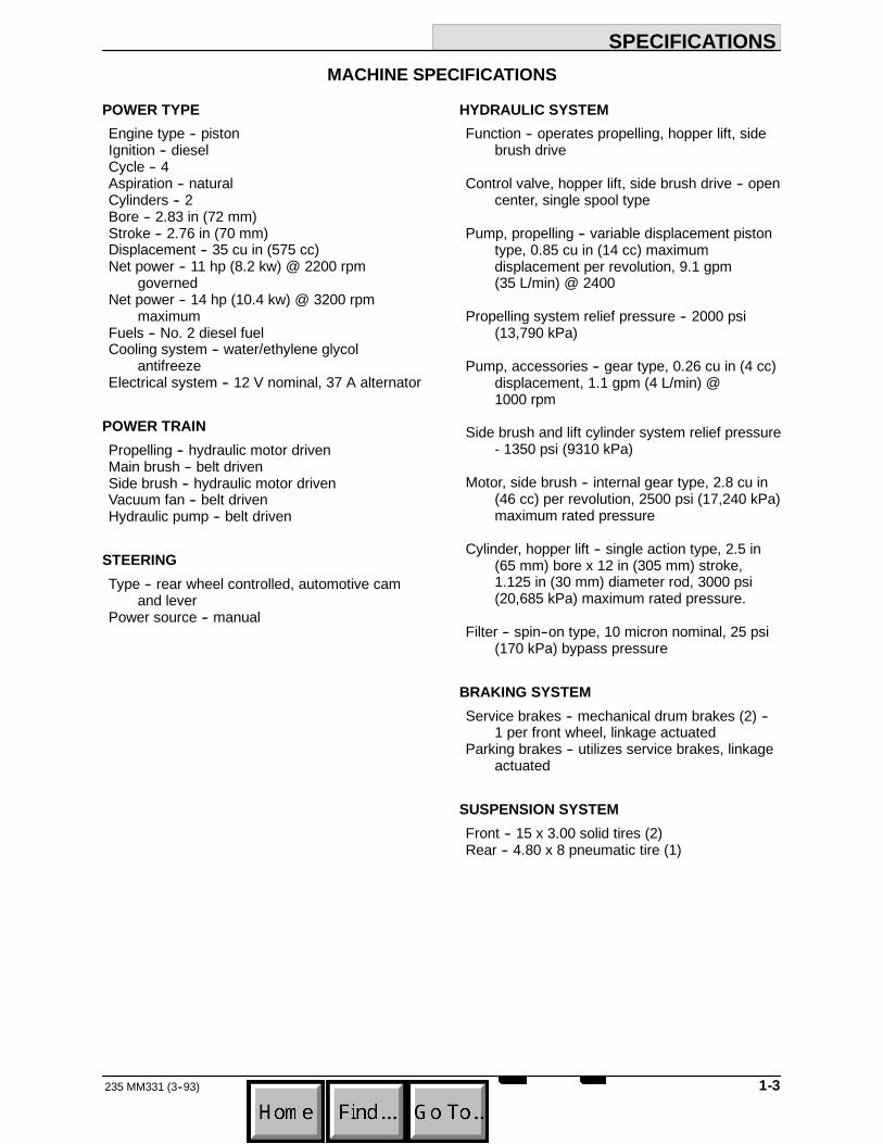
MACHINE SPECIFICATIONS
POWER TYPEEngine type -- pistonIgnition -- dieselCycle -- 4Aspiration -- naturalCylinders -- 2Bore -- 2.83 in (72 mm)Stroke -- 2.76 in (70 mm)Displacement -- 35 cu in (575 cc)Net power -- 11 hp (8.2 kw) @ 2200 rpm
governedNet power -- 14 hp (10.4 kw) @ 3200 rpm
maximumFuels -- No. 2 diesel fuelCooling system -- water/ethylene glycol
antifreezeElectrical system -- 12 V nominal, 37 A alternator
POWER TRAINPropelling -- hydraulic motor drivenMain brush -- belt drivenSide brush -- hydraulic motor drivenVacuum fan -- belt drivenHydraulic pump -- belt driven
STEERINGType -- rear wheel controlled, automotive cam
and leverPower source -- manual
HYDRAULIC SYSTEMFunction -- operates propelling, hopper lift, side
brush drive
Control valve, hopper lift, side brush drive -- opencenter, single spool type
Pump, propelling -- variable displacement pistontype, 0.85 cu in (14 cc) maximumdisplacement per revolution, 9.1 gpm(35 L/min) @ 2400
Propelling system relief pressure -- 2000 psi(13,790 kPa)
Pump, accessories -- gear type, 0.26 cu in (4 cc)displacement, 1.1 gpm (4 L/min) @1000 rpm
Side brush and lift cylinder system relief pressure- 1350 psi (9310 kPa)
Motor, side brush -- internal gear type, 2.8 cu in(46 cc) per revolution, 2500 psi (17,240 kPa)maximum rated pressure
Cylinder, hopper lift -- single action type, 2.5 in(65 mm) bore x 12 in (305 mm) stroke,1.125 in (30 mm) diameter rod, 3000 psi(20,685 kPa) maximum rated pressure.
Filter -- spin--on type, 10 micron nominal, 25 psi(170 kPa) bypass pressure
BRAKING SYSTEMService brakes -- mechanical drum brakes (2) --
1 per front wheel, linkage actuatedParking brakes -- utilizes service brakes, linkage
actuated
SUSPENSION SYSTEMFront -- 15 x 3.00 solid tires (2)Rear -- 4.80 x 8 pneumatic tire (1)

SPECIFICATIONS
235 MM331 (3--93)1-4
SYSTEM FLUID CAPACITIESHydraulic system -- reservoir 3.9 gal (14.8 L)Hydraulic system -- total 4.4 gal (16.7 L)
Engine lubricating oil, with filter -- 3.2 qt (3 L)Engine cooling system -- 3.2 qt (3 L)
Fuel tank -- 7.3 gal (28L)
GENERAL MACHINE DIMENSIONS --CAPACITIESLength -- 77.5 in (1970 mm)Width with side brush -- 48 in (1220 mm)Height without overhead guard -- 53 in (1345
mm)Height with overhead guard -- 79.5 in (2020 mm)
Track -- front 44 in (1115 mm)Wheel base -- 41 in (1040 mm)
Main brush -- width 36 in (915 mm)Main brush outside diameter -- 14 in (355 mm)Side brush rotary diameter -- 19 in (480 mm)Sweeping path width (total) -- 48 in (1220 mm)
Hopper capacity -- 10 cu ft (0.28 m#) 650 lb(295 kg)
Dust filter -- 49 sq ft (4.5 m@), pleated panel filterelement
MACHINE WEIGHTSNet weight, dry -- 1840 lb (835 kg)GVWR -- 2780 lb (1260 kg)
GENERAL MACHINE PERFORMANCEMaximum forward speed -- 6 mph (10 km/h)Maximum reverse speed -- 3 mph (5 km/h)Maximum forward speed with raised hopper --
2 mph (3.2 km/h)
Turning radius -- left, 60 in (1525 mm) right, 78 in(1980 mm)
Maximum rated climb and descent angle -- 10_

SPECIFICATIONS
1-5235 MM331 (3--93)
MACHINE DIMENSIONS
SIDE VIEW
TOP VIEW
77.5 in (1970 mm)
48 in(1220 mm)
53 in(1345 mm)
03366

SPECIFICATIONS
235 MM331 (3--93)1-6

OPERATION
2-1235 MM331 (8--95)
SECTION 2CONTENTS
PagePREPARATION FOR OPERATION 2-3. . . . . . .
AFTER UNCRATING AND BEFOREOPERATING MACHINE: 2-3. . . . . . . . . .
OPERATION OF CONTROLS 2-4. . . . . . . . . . .MACHINE COMPONENTS 2-4. . . . . . . . . . .CONTROLS AND INSTRUMENTS 2-5. . . .BRAKE PEDAL 2-6. . . . . . . . . . . . . . . . . . . . .DIRECTIONAL PEDAL 2-6. . . . . . . . . . . . . . .PARKING BRAKE LEVER 2-6. . . . . . . . . . . .OPERATOR SEAT 2-6. . . . . . . . . . . . . . . . . .ADJUSTABLE SEAT LEVER (OPTION) 2-6SEAT SUPPORT LEVER 2-6. . . . . . . . . . . . .SIDE BRUSH AND HOPPER LEVER 2-6. .THROTTLE LEVER 2-6. . . . . . . . . . . . . . . . .TEMP LIGHT 2-6. . . . . . . . . . . . . . . . . . . . . . .AMPS LIGHT 2-6. . . . . . . . . . . . . . . . . . . . . . .OIL PRESSURE LIGHT 2-7. . . . . . . . . . . . . .HOPPER DOOR SWITCH 2-7. . . . . . . . . . . .LIGHT SWITCH 2-7. . . . . . . . . . . . . . . . . . . . .KEY-OPERATED IGNITION SWITCH 2-7. .MAIN BRUSH LEVER 2-7. . . . . . . . . . . . . . . .GLOW PLUG INDICATOR 2-7. . . . . . . . . . . .VACUUM LEVER 2-7. . . . . . . . . . . . . . . . . . . .HOUR METER 2-7. . . . . . . . . . . . . . . . . . . . . .FUEL LEVEL GAUGE 2-7. . . . . . . . . . . . . . .FLASHER SWITCH 2-7. . . . . . . . . . . . . . . . .STEERING WHEEL 2-7. . . . . . . . . . . . . . . . .HORN BUTTON 2-7. . . . . . . . . . . . . . . . . . . . .SIDE BRUSH LEVER 2-8. . . . . . . . . . . . . . . .SIDE BRUSH ADJUSTMENT KNOB 2-8. . .AUXILIARY SIDE BRUSH
IN-OUT SWITCH 2-8. . . . . . . . . . . . . . . . .AUXILIARY SIDE BRUSH
UP-DOWN SWITCH 2-8. . . . . . . . . . . . . .CIRCUIT BREAKERS 2-9. . . . . . . . . . . . . . . .HOPPER SUPPORT BAR 2-9. . . . . . . . . . . .
PageMACHINE OPERATION 2-10. . . . . . . . . . . . . . . . .
NORMAL SWEEPING OPERATION 2-10. . .PRE-START CHECKLIST 2-10. . . . . . . . .TO START MACHINE 2-10. . . . . . . . . . . . .TO SWEEP 2-11. . . . . . . . . . . . . . . . . . . . . .TO DUMP HOPPER 2-11. . . . . . . . . . . . . .POST OPERATION CHECKLIST --
ENGINE OPERATING 2-11. . . . . . . . . .TO STOP MACHINE 2-12. . . . . . . . . . . . . .POST OPERATION CHECKLIST --
ENGINE STOPPED 2-12. . . . . . . . . . . .TO ENGAGE HOPPER SUPPORT BAR 2-12TO DISENGAGE HOPPER
SUPPORT BAR 2-13. . . . . . . . . . . . . . . . . .OPERATION ON GRADES 2-13. . . . . . . . . . .MACHINE TROUBLESHOOTING 2-14. . . . .
TRANSPORTING MACHINE 2-15. . . . . . . . . . . .PUSHING OR TOWING MACHINE 2-15. . . .MACHINE JACKING 2-15. . . . . . . . . . . . . . . . .
TO JACK UP MACHINE 2-15. . . . . . . . . . .MACHINE TIE-DOWNS 2-16. . . . . . . . . . . . . .
MACHINE STORAGE 2-17. . . . . . . . . . . . . . . . . .STORING MACHINE 2-17. . . . . . . . . . . . . . . .
OPERATION
235 MM331 (3--93)2-2

OPERATION
2-3235 MM331 (3--93)
PREPARATION FOR OPERATION
AFTER UNCRATING AND BEFOREOPERATING MACHINE:
1. Check the machine for shipping damage.
2. Read this manual carefully before operatingor servicing the machine.
FOR SAFETY: Do Not Operate Machine,Unless Operation Manual Is Read AndUnderstood.
3. Check the hydraulic fluid level in thehydraulic fluid reservoir. See HYDRAULICSin the MAINTENANCE section.
4. Check the main brush adjustment. SeeBRUSHES in the MAINTENANCE section.
5. Check the engine oil level. See ENGINE inthe MAINTENANCE section.
6. Fill the fuel tank on the machine.
FOR SAFETY: When Servicing Machine, KeepFlames And Sparks Away From Fuel SystemService Area. Keep Area Well Ventilated.
7. Check the radiator coolant level in thecoolant tank.

OPERATION
235 MM331 (3--93)2-4
OPERATION OF CONTROLS
AB
C
D
E
H
G
F
03486MACHINE COMPONENTS
A. Operator Seat E. HopperB. Seat Support F. Hopper Inspection DoorC. Steering Wheel G. Side BrushD. Filter Cover H. Access Door
OPERATION
2-5235 MM331 (3--94)
T
A
B
C
V
O
P
NQ
ML
KJ
IH
E
G
F
D
R
S
U
W
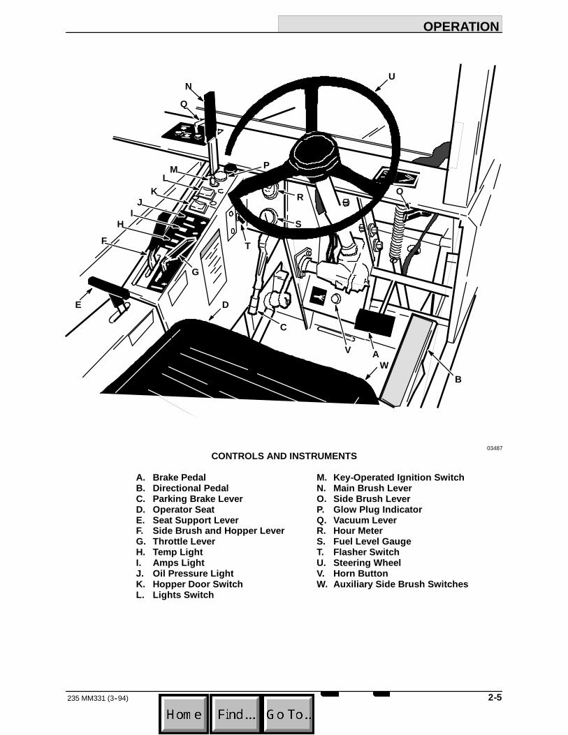
03487CONTROLS AND INSTRUMENTS
A. Brake Pedal M. Key-Operated Ignition SwitchB. Directional Pedal N. Main Brush LeverC. Parking Brake Lever O. Side Brush LeverD. Operator Seat P. Glow Plug IndicatorE. Seat Support Lever Q. Vacuum LeverF. Side Brush and Hopper Lever R. Hour MeterG. Throttle Lever S. Fuel Level GaugeH. Temp Light T. Flasher SwitchI. Amps Light U. Steering WheelJ. Oil Pressure Light V. Horn ButtonK. Hopper Door Switch W. Auxiliary Side Brush SwitchesL. Lights Switch

OPERATION
235 MM331 (8--95)2-6
BRAKE PEDALThe brake pedal operates the brakes on the twofront wheels. To stop the machine, return thedirection pedal to neutral, then apply pressure tothe brake pedal.
DIRECTIONAL PEDALThe directional pedal controls the propelling drive.It is used to select the direction of travel and thespeed of the machine.
AB
C
E
D
00116DIRECTIONAL PEDAL POSITIONS
A. “Reverse” PositionB. “Neutral” PositionC. “Forward” PositionD. “Heel” PositionE. “Toe” Position
Gradually press the “toe”portion of the pedal forforward travel or the “heel”portion for reversetravel. Regulate the machine speed by varying thepressure on the directional pedal.
PARKING BRAKE LEVERThe parking brake lever operates the front wheelbrakes. To set the parking brake, pull the handleup. To release the parking brake, push the handledown. Always park on a level surface, stop theengine, and set the parking brake before leavingthe machine unattended and before working onthe machine.
FOR SAFETY: Before Leaving Or ServicingMachine; Stop On Level Surface, Set ParkingBrake, Turn Off Machine And Remove Key.
OPERATOR SEATThe operator seat is of the fixed-back style with aforward-backward adjustment. To adjust the seat,remove the seat mounting bolts, slide the seat tothe position desired, and reinstall and tighten thebolts.
ADJUSTABLE SEAT LEVER (OPTION)The adjustable seat lever option controls thefront-to-rear position of the seat. Pull the leverout, slide the seat backward or forward to thedesired position and release the lever.
SEAT SUPPORT LEVERThe seat support lever locks the seat supportdown. To raise the seat support, pull the lever andseat support back. To lower the seat support, holdon to the lever and lower the seat support. Do notlet the seat support drop or machine damage mayoccur.
SIDE BRUSH AND HOPPER LEVERThe side brush and hopper lever controls sidebrush rotation and hopper position. To start theside brush turning, push the lever forward into the“ON”position. To stop the side brush, pull thelever back into the “LOWER”position. To raise thehopper, pull the lever back into the “LIFT”position. To hold the hopper in any raised position,pull the lever back into the “HOLD”position. Tolower the hopper, push the lever forward into the“LOWER”position.
THROTTLE LEVERThe throttle lever control is spring loaded intoforward “ON”position. To stop the engine, pullthe lever back into the “OFF”position.
TEMP LIGHTThe temp light indicates when the engine isoverheating. If the light glows, stop the engineimmediately and determine the cause. Failure tostop the engine will result in engine damage.
Engine overheating may happen because of lowcoolant level, a clogged radiator or cooling fins, aloose fan belt, or other engine malfunctions.Engine overheating will always cause coolantloss. If coolant loss does not occur, check for adefective temperature sending unit.
AMPS LIGHTThe amps light indicates when the electricalsystem is not operating properly. If the light glows,stop the engine and determine the cause.
The electrical system may not be accepting orgetting a charge from the alternator. Overchargingand undercharging are indications that one ormore electrical components are in need of repair.

OPERATION
2-7235 MM331 (3--93)
OIL PRESSURE LIGHTThe engine oil pressure light indicates inadequateengine oil pressure. If the light glows, stop theengine immediately and determine the cause.Failure to stop the engine will result in enginedamage.
HOPPER DOOR SWITCHThe hopper door switch controls the hopper door.To open the hopper door, press and hold theswitch in the “OPEN”position until a ratchetingnoise is heard. To close the hopper door, pressand hold the switch in the “CLOSE”position untila ratcheting noise is heard. The hopper doorshould always be open except when highdumping the hopper.
LIGHT SWITCHThe light switch operates the head lights and thetail lights.To operate the lights, move the switch tothe “ON”position. To turn off the lights, move theswitch to the “OFF”position.
KEY-OPERATED IGNITION SWITCHThe key-operated ignition switch has fourpositions: “PREHEAT,”“OFF,”“ON,”and “START.”To start the engine, turn the key counterclockwiseto the “PREHEAT”position until the glow plugindicator glows brightly -- usually 15 to 30seconds. Then turn key fully clockwise to the“START”position. Release the key as soon as theengine starts and the key will return to the “ON”position. To stop the engine, turn the key to the“OFF”position.
FOR SAFETY: Before Starting Machine, MakeSure All Safety Devices Are In Place AndOperate Properly.
MAIN BRUSH LEVERThe main brush lever controls the position and thedrive of the main brush. To raise the main brush,push the lever all the way forward into the “UP”position. To lower the main brush, push the leverforward and to the left, and release it.
When parking the machine, always raise thebrush to prevent the bristles from taking a set.
GLOW PLUG INDICATORThe glow plug indicator glows brightly when thepreheaters are up to starting temperature.
To use engine preheaters, turn and hold theignition key to the “preheat”position until theindicator glows brightly -- usually 15 to30 seconds. Then start the engine.
VACUUM LEVERThe vacuum lever controls the vacuum that isapplied to the hopper. The lever also controls thedust filter shaker. When sweeping dry debris,place the lever in the “Normal Sweeping”position.When sweeping wet debris, place the lever in the“Wet Sweeping”position. To shake the dust filter,place and hold the lever in the “Filter Shaker”position for 20 seconds.
HOUR METERThe hour meter records the number of hours themachine has operated. This information is usefulin determining when to service the machine.
FUEL LEVEL GAUGEThe fuel level gauge on a diesel powered machineindicates how much fuel is left in the fuel tank.
FLASHER SWITCHThe flasher switch is present on machines withthe flashing light option. To operate the flashinglight, move the switch to the “ON”position. Tostop the light, move the switch to the “OFF”position.
STEERING WHEELThe steering wheel controls the rear caster wheel.The machine is very responsive to the movementof the steering wheel. The operator should usecare until he or she becomes experienced inguiding the machine.
HORN BUTTONThe horn button operates the machine horn. It islocated to the left of the foot brake pedal.

OPERATION
235 MM331 (3--94)2-8
SIDE BRUSH LEVERThe side brush lever controls the position of theside brush. To raise the side brush, pull the leverinto the “Raised”position. To lower the brush,push the lever down and release it into the“Down”position.
When the machine is parked, always raise thebrush to prevent the bristles from taking a set.
03396SIDE BRUSH LEVER
SIDE BRUSH ADJUSTMENT KNOBThe side brush adjustment knob controls theheight of the side brush when it is in the “Down”position. To reduce the brush pattern and the sidebrush contact with the floor, turn the knob to theright. To increase the brush pattern and the sidebrush contact with the floor, turn the knob to theleft.
B
A
03386SIDE BRUSH ADJUSTMENT KNOB
A. Side Brush Adjustment KnobB. Hopper
AUXILIARY SIDE BRUSH IN-OUT SWITCH(OPTION)The auxiliary side brush in-out switch controls thein and out movement of the auxiliary side brushoption. To move the brush in, press the top of thein-out switch.To move the brush out, press thebottom of the in-out switch.
BA
AUXILIARY SIDE BRUSH SWITCHES
A. Up-Down SwitchB. In-out Switch
AUXILIARY SIDE BRUSH UP-DOWN SWITCH(OPTION)The auxiliary side brush up-down switch controlsthe up and down movement of the auxiliary sidebrush option. To raise the brush, press the top ofthe up-down switch.To lower the brush, press thebottom of the up-down switch.

OPERATION
2-9235 MM331 (3--93)
CIRCUIT BREAKERSCircuit breakers are resetable circuit protectiondevices designed to stop the flow of current in theevent of a circuit overload. Once tripped, circuitbreakers must be manually reset. If the overloadwhich caused the circuit breaker to trip is stillpresent in the circuit, the circuit breaker willcontinue to stop current flow until the overload iscorrected.
The circuit breakers are located on the instrumentpanel bracket under the seat support.
The following chart shows the various circuitbreakers and the electrical components theyprotect.
PROTECTIVE CIRCUITDEVICE RATING PROTECTEDCB--1 15 A ControlsCB--2 10 A HornCB--3 10 A Filter ShakerCB--4 10 A Hopper Dump DoorCB--5 7 A Hopper Dump Door,
Thermo Sentryt andAir Flow Solenoids
CB--6 15 A Lights
A
B
03491CIRCUIT BREAKERS
A. Instrument Panel BracketB. Circuit Breakers
HOPPER SUPPORT BARThe hopper support bar is located on the rightside lift arm. It holds the hopper in a raisedposition to allow work to be done under thehopper. Do not rely on the machine hydraulicsystem to keep the hopper raised.
WARNING: Raised Hopper May Fall.Engage Hopper Support Bar.

OPERATION
235 MM331 (3--94)2-10
MACHINE OPERATION
NORMAL SWEEPING OPERATIONA normal sweeping operation consists of seventypical operations: pre-start checklist, startingmachine, sweeping, dumping hopper, postoperation checklist -- engine operating, stoppingmachine, and post operation checklist -- enginestopped.
The PRE-START CHECKLIST lists things tocheck before starting the machine.
TO START MACHINE lists the steps required tostart the machine.
TO SWEEP lists things to keep in mind beforeand during the sweeping operation.
TO DUMP HOPPER lists the steps required todump the hopper.
POST OPERATION CHECKLIST -- ENGINEOPERATING lists things to check before stoppingthe machine engine.
TO STOP MACHINE lists the steps required tostop the machine.
The POST OPERATION CHECKLIST -- ENGINESTOPPED lists things to check after stopping themachine engine.
PRE-START CHECKLISTCheck under the machine for leak spots.
Check the engine lubricating oil level.
Check the fuel level.
Check the brakes and controls for properoperation.
Check the service records to determine servicerequirements.
TO START MACHINENOTE: Before starting machine, perform thepre-start checks.
1. Turn the ignition switch key to the“PREHEAT”position until the glow plugindicator glows brightly.
2. The machine operator must be in theoperator’s seat with the directional pedal inthe “neutral”position and with a foot on thebrake pedal or with the parking brake set.
FOR SAFETY: Before Starting Machine; MakeSure All Safety Devices Are In Place AndOperate Properly, Check Brakes And SteeringFor Proper Operation.
3. Turn the ignition switch key to the “START”position until the engine starts. Then releasethe key to the ”on”postition.
NOTE: Do not operate the starter motor for morethan 10 seconds at a time or after the engine hasstarted. Allow the starter to cool between startingattempts. The starter motor may be damaged if itis operated incorrectly.
4. Allow the engine and hydraulic system towarm up three to five minutes.
5. Release the machine parking brake.
6. Move the throttle control lever to the “FULL”position, and drive the machine to the areato be swept.

OPERATION
2-11235 MM331 (3--93)
TO SWEEPPlan the sweeping in advance. Try to arrange longruns with minimum stopping and starting. Sweepdebris from very narrow aisles into main aislesahead of time. Do an entire floor or section at onetime. Overlap brush paths.
Pick up oversize debris before sweeping. Flattenor remove bulky cartons from aisles beforesweeping. Pick up pieces of wire, twine, string,etc., which could become entangled in brush orbrush plugs. Place large debris in hopper throughhopper inspection door.
Avoid turning the steering wheel too sharply whenthe machine is in motion. The machine is veryresponsive to the movement of the steeringwheel. Avoid sudden turns, except inemergencies.
Sweep as straight a path as possible. Avoidbumping into posts or scraping the sides of thesweeper.
1. Move the vacuum lever to the “NormalSweeping”position to sweep dry debris, or“Wet Sweeping”position to sweep wetdebris.
2. Push the main brush lever forward and tothe left, then release the lever to lower themain brush.
3. Move the side brush lever into the “Down”position.
4. Push the side brush and hopper lever intothe “ON”position.
5. Press and hold the hopper door switch in the“OPEN”position.
6. Sweep as required.
TO DUMP HOPPER1. Push the main brush lever into the “UP”
position.
2. Pull the side brush lever into the “Raised”position.
3. Move the vacuum lever to the “Filter Shaker”position for 20 seconds to shake the dustfilter.
4. Slowly drive the machine up to the dumpsite or dumpster.
5. Press and hold the hopper door switch in the“CLOSE”position.
6. Pull the side brush and hopper lever to the“LIFT”position, then into the “HOLD”position when at the desired dump height.
7. Press and hold the hopper door switch in the“OPEN”position to dump the hopper.
8. Press and hold the hopper door switch in the“CLOSE”position to close the hopper door.
9. Slowly back the machine away from thedump site or dumpster.
10. Push the side brush and hopper lever to the“LOWER”position to lower the hopper.
11. Press and hold the hopper door switch in the“OPEN”position to open the hopper door.
POST OPERATION CHECKLIST -- ENGINEOPERATINGCheck brush patterns for width and evenness.

OPERATION
235 MM331 (3--93)2-12
TO STOP MACHINE1. Return the directional pedal to the “neutral”
position. Apply the brake.
2. Push the main brush lever into the “UP”position.
3. Pull the side brush lever back into the“Raised”position.
4. Pull the side brush and hopper lever into the“LOWER”position to stop the side brush.
5. Set the machine parking brake.
6. Pull the throttle control lever in the “STOP”position.
7. Turn the key-operated ignition switch key tothe “OFF”position. Remove the key fromthe ignition switch.
FOR SAFETY: Before Leaving Or ServicingMachine; Stop On Level Surface, Set ParkingBrake, Turn Off Machine And Remove Key.
POST OPERATION CHECKLIST -- ENGINESTOPPEDCheck the skirts for damage, wear, andadjustment.
Check for wire or string tangled on the brushes.
Check for leaks.
TO ENGAGE HOPPER SUPPORT BARWARNING: Raised Hopper May Fall.Engage Hopper Support Bar.
1. Set the machine parking brake.
FOR SAFETY: Before Leaving Or ServicingMachine; Stop On Level Surface, Set ParkingBrake, Turn Off Machine And Remove Key.
2. Raise the hopper.
3. Position the hopper support bar on the barstand.
B
A
03369HOPPER SUPPORT BAR STAND
A. Bar StandB. Support Bar

OPERATION
2-13235 MM331 (3--93)
4. Slowly lower the hopper so the bar issecure.
A
B
03370ENGAGED HOPPER SUPPORT BAR
A. Lift ArmB. Support Bar
TO DISENGAGE HOPPER SUPPORT BAR1. Raise the hopper.
2. Place the support bar in its storage position.
3. Lower the hopper.
OPERATION ON GRADESDrive the machine slowly on grades. Use thebrake pedal to control machine speed.
FOR SAFETY: When Using Machine, Go SlowOn Grades And Slippery Surfaces.
The maximum rated climb and descent angle is10_.

OPERATION
235 MM331 (3--93)2-14
MACHINE TROUBLESHOOTING
Problem Cause RemedyExcessive dusting Dust skirts and seals worn,
damaged, not adjusted properlyReplace or adjust skirts or seals
Dust filter clogged Shake and clean or replace filterVacuum hose damaged Replace vacuum hoseVacuum fan failure Belt loose, broken or off sheave
Poor sweeping performance Brush bristles worn Replace brushesPoor sweeping performanceBrushes not adjusted properly Adjust brushesDebris caught in brush drivemechanism
Free mechanism of debris
Main brush drive failure Belt loose, broken or off sheaveSide brush drive failure See HYDRAULIC SYSTEM
TROUBLESHOOTING: Sidebrush turns slowly or not at all
Hopper not adjusted properly Adjust hopper floor clearanceHopper dump door closed Open dump doorHopper full Empty hopperHopper floor skirts worn, damaged Replace skirts

OPERATION
2-15235 MM331 (3--93)
TRANSPORTING MACHINE
PUSHING OR TOWING MACHINEThe machine may be slowly pushed from the frontor rear, pushing on the bumper or the machineframe.
The machine may be slowly towed from the front.Use care when attaching towing cables or chainsto avoid damaging the machine.
MACHINE JACKINGThe machine may be jacked up for service at thedesignated locations. Use a jack of adequatecapacity and good working condition. Always stopthe machine on a flat, level surface and block thetires before jacking the machine up.
The front jacking locations are on the flat bottomedge of the machine frame next to the front tires.The rear jacking location is the middle flat bottomedge of the rear bumper.
TO JACK UP MACHINE1. Empty and lower the debris hopper.
2. Stop the engine and set the machineparking brake.
FOR SAFETY: Before Leaving Or ServicingMachine; Stop On Level Surface, Set ParkingBrake, Turn Off Machine And Remove Key.
3. Block the tires, which are not being jackedup, in order to secure the machine position.
FOR SAFETY: When Servicing Machine, BlockMachine Tires Before Jacking Machine Up.
4. Use a jack of adequate capacity to raise themachine. Jack up the machine only at thedesignated locations.
FOR SAFETY: When Servicing Machine, UseHoist Or Jack Of Adequate Capacity To LiftMachine, Jack Machine Up At DesignatedLocations Only. Block Machine Up With JackStands.
A03372
FRONT JACKING LOCATION
A. Jacking Location
A
03373REAR JACKING LOCATION
A. Jacking Location
5. Block machine up with jack stands or similardevices in the designated locations tosecure the machine.
FOR SAFETY: When Servicing Machine, JackMachine Up At Designated Locations Only.Block Machine Up With Jack Stands.

OPERATION
235 MM331 (3--93)2-16
6. Lower the machine onto the jack stands.
7. Check to make sure the machine is secure.
8. Service the machine as required.
9. When finished servicing the machine, raisethe machine off the jack stands.
10. Remove the jack stands from under themachine.
11. Lower the machine.
12. Remove the blocks from the tires.
MACHINE TIE-DOWNSThe machine may be tied down at each corner ofthe main frame using the tie-down bracketssupplied in the tie-down kit.
A
03372FRONT TIE-DOWN LOCATION
A. Tie-Down Bracket
When transporting the machine on a trailer or in atruck, be sure to set the machine parking brakeand block the machine tires to prevent themachine from rolling.

OPERATION
2-17235 MM331 (3--93)
MACHINE STORAGE
STORING MACHINEWhen storing the machine for extended periods oftime, the following procedures must be followed tolessen the chance of rust, sludge, or otherundesirable deposits from forming.
1. Empty the debris hopper.
2. Change the engine oil.
3. Raise the main brush and side brush.
4. Park the machine on a level surface in acool, dry area.
5. Stop the engine and set the machineparking brake.
6. Fill the hydraulic reservoir with hydraulic fluidto prevent excessive condensation fromforming.
7. To store the machine 30 to 90 days:
A. Drain the coolant from the radiator andengine block.
B. Close the engine cooling system draincocks.
To store the machine 90 days to 6 monthsalso:
C. Seal the air cleaner inlet and theexhaust outlet with weatherproofmasking tape.
D. Tighten the engine oil filler cap, the fueltank cap, and the radiator cap to makecertain they are securely in place.

OPERATION
235 MM331 (3--93)2-18

MAINTENANCE
3-1235 MM331 (8--95)
SECTION 3CONTENTS
PageRECOMMENDED FIRST 50-HOUR
MACHINE INSPECTION 3-3. . . . . . . . . . . . .MAINTENANCE CHART 3-4. . . . . . . . . . . . . . . .LUBRICATION 3-6. . . . . . . . . . . . . . . . . . . . . . . . .
ENGINE 3-6. . . . . . . . . . . . . . . . . . . . . . . . . . .SIDE BRUSH LEVER PIVOT 3-6. . . . . . . . .REAR WHEEL SUPPORT BEARING 3-7. .STEERING LINKAGE 3-7. . . . . . . . . . . . . . . .
HYDRAULICS 3-8. . . . . . . . . . . . . . . . . . . . . . . . .HYDRAULIC FLUID 3-8. . . . . . . . . . . . . . . . .HYDRAULIC FLUID RESERVOIR 3-8. . . . .HYDRAULIC FILTER 3-8. . . . . . . . . . . . . . . .
TO REPLACE FILTER ELEMENT 3-9. .HYDRAULIC PUMPS 3-9. . . . . . . . . . . . . . . .
TO START AND BREAK-INHYDRAULIC PUMP 3-9. . . . . . . . . . . .
DIRECTIONAL PEDAL 3-10. . . . . . . . . . . . . . .TO ADJUST DIRECTIONAL
PEDAL LINKAGE 3-10. . . . . . . . . . . . . .LIFT ARM SPEED LIMITER 3-11. . . . . . . . . .HYDRAULIC FLUID LEAKS 3-12. . . . . . . . . .HYDRAULIC SCHEMATIC 3-13. . . . . . . . . . .HYDRAULIC SYSTEM
TROUBLESHOOTING 3-14. . . . . . . . . . . .HYDRAULIC COMPONENTS
TROUBLESHOOTING 3-15. . . . . . . . . . . .ENGINE 3-16. . . . . . . . . . . . . . . . . . . . . . . . . . . . . . .
ENGINE LUBRICATION 3-16. . . . . . . . . . . . . .COOLING SYSTEM 3-16. . . . . . . . . . . . . . . . .AIR INTAKE SYSTEM 3-17. . . . . . . . . . . . . . .AIR FILTER 3-18. . . . . . . . . . . . . . . . . . . . . . . .
TO REPLACE AIRFILTER ELEMENT 3-18. . . . . . . . . . . . .
FUEL SYSTEM 3-19. . . . . . . . . . . . . . . . . . . . .FUEL SYSTEM 3-19. . . . . . . . . . . . . . . . . .FUEL WATER TRAP FILTER 3-19. . . . . .TO REPLACE FUEL
FILTER ELEMENT 3-19. . . . . . . . . . . . .PRIMING FUEL SYSTEM 3-20. . . . . . . . .TO PRIME FUEL SYSTEM 3-20. . . . . . . .
DIESEL FUEL TROUBLESHOOTING 3-21. .CYLINDER HEAD 3-22. . . . . . . . . . . . . . . . . . .
CYLINDER HEAD 3-22. . . . . . . . . . . . . . . .VALVE CLEARANCE 3-22. . . . . . . . . . . . .DECOMPRESSION LEVER 3-22. . . . . . .
ELECTRICAL SYSTEM 3-23. . . . . . . . . . . . . . . . .BATTERY 3-23. . . . . . . . . . . . . . . . . . . . . . . . . .ELECTRICAL SCHEMATIC 3-24. . . . . . . . . . .ELECTRICAL SCHEMATIC,
AUXILIARY SIDE BRUSH 3-25. . . . . . . . .BELTS AND CHAINS 3-26. . . . . . . . . . . . . . . . . . .
HYDRAULIC PUMP BELT 3-26. . . . . . . . . . . .TO REPLACE AND ADJUST
HYDRAULIC PUMP BELT 3-26. . . . . . .
PageVACUUM FAN BELT 3-26. . . . . . . . . . . . . . . . .
TO REPLACE AND ADJUSTVACUUM FAN BELT 3-26. . . . . . . . . . .
MAIN BRUSH BELT 3-28. . . . . . . . . . . . . . . . .TO REPLACE MAIN BRUSH BELT 3-28.
FAN BELT 3-28. . . . . . . . . . . . . . . . . . . . . . . . . .TO REPLACE AND ADJUST
FAN BELT 3-28. . . . . . . . . . . . . . . . . . . .TAPER LOCK BUSHINGS 3-30. . . . . . . . . . . .
TO REMOVE TAPERLOCK BUSHING 3-30. . . . . . . . . . . . . .
TO INSTALL TAPERLOCK BUSHING 3-30. . . . . . . . . . . . . .
STATIC DRAG CHAIN 3-30. . . . . . . . . . . . . . .DEBRIS HOPPER AND DUST FILTER 3-31. . .
DEBRIS HOPPER 3-31. . . . . . . . . . . . . . . . . . .TO CHECK AND ADJUST HOPPER
FLOOR CLEARANCE 3-31. . . . . . . . . . . . .THERMO SENTRYt 3-31. . . . . . . . . . . . . . . .
TO CHECK THETHERMO SENTRYt 3-31. . . . . . . . . .
HOPPER DUST FILTER 3-32. . . . . . . . . . . . .TO REMOVE AND REPLACE
HOPPER DUST FILTER 3-33. . . . . . . . . . .BRUSHES 3-34. . . . . . . . . . . . . . . . . . . . . . . . . . . .
MAIN BRUSH 3-34. . . . . . . . . . . . . . . . . . . . . . .TO REMOVE MAIN BRUSH 3-34. . . . . . .TO INSTALL MAIN BRUSH 3-34. . . . . . . .TO CHECK AND ADJUST MAIN
BRUSH PATTERN 3-34. . . . . . . . . . . . .SIDE BRUSH 3-36. . . . . . . . . . . . . . . . . . . . . . .
TO REMOVE SIDE BRUSH 3-36. . . . . . . .TO INSTALL SIDE BRUSH 3-36. . . . . . . .
SKIRTS AND SEALS 3-37. . . . . . . . . . . . . . . . . . .BRUSH SKIRTS 3-37. . . . . . . . . . . . . . . . . . . .
TO REPLACE AND ADJUSTBRUSH SKIRTS 3-37. . . . . . . . . . . . . . .
REAR SKIRTS 3-37. . . . . . . . . . . . . . . . . . . . . .TO REPLACE AND ADJUST
REAR SKIRTS 3-37. . . . . . . . . . . . . . . .HOPPER LIP SKIRT 3-38. . . . . . . . . . . . . . . . .
TO REPLACE HOPPER LIP SKIRT 3-38.DUST SEALS 3-38. . . . . . . . . . . . . . . . . . . . . . .
TO REPLACE DUST SEALS 3-38. . . . . . .HOPPER DUMP DOOR SEAL 3-39. . . . . . . .
TO REPLACE HOPPER DUMPDOOR SEAL 3-39. . . . . . . . . . . . . . . . . .
VACUUM FAN SEAL 3-40. . . . . . . . . . . . . . . . .FILTER COVER SEAL 3-40. . . . . . . . . . . . . . .
BRAKES AND TIRES 3-41. . . . . . . . . . . . . . . . . . .BRAKES 3-41. . . . . . . . . . . . . . . . . . . . . . . . . . .TIRES 3-41. . . . . . . . . . . . . . . . . . . . . . . . . . . . . .REAR WHEEL 3-41. . . . . . . . . . . . . . . . . . . . . .

MAINTENANCE
235 MM331 (3--93)3-2

MAINTENANCE
3-3235 MM331 (8--95)
RECOMMENDED FIRST 50-HOUR MACHINE INSPECTION
After the first 50 hours of operation, the followingprocedures are recommended:
1. Check the floor skirts to floor clearance. SeeSKIRTS AND SEALS.
2. Check the side brush and main brushpatterns. See BRUSHES.
3. Change the engine oil after the first 35hours of operation.
4. Replace hydraulic fluid filter element.
5. Torque the rear wheel nuts in a star patternto 122 to 150 Nm (90 to 110 ft lb).See REAR WHEEL.
6. Perform all 50-hour interval lubrication andmaintenance procedures listed in theMAINTENANCE CHART.
MAINTENANCE
235 MM331 (3--94)3-4
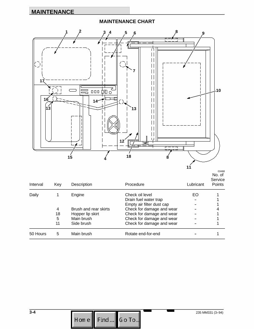
MAINTENANCE CHART
13
7
16
13
15 4
14
8
11
10
98654321
17
12
18
03488No. of
ServiceInterval Key Description Procedure Lubricant Points
Daily 1 Engine Check oil level EO 1Drain fuel water trap -- 1Empty air filter dust cap -- 1
4 Brush and rear skirts Check for damage and wear -- 418 Hopper lip skirt Check for damage and wear -- 15 Main brush Check for damage and wear -- 111 Side brush Check for damage and wear -- 1
50 Hours 5 Main brush Rotate end-for-end -- 1

MAINTENANCE
3-5235 MM331 (8--95)
No. ofService
Interval Key Description Procedure Lubricant Points
100 Hours 1 Engine Clean or replace air -- 1filter element
Change oil and oil filter EO 1Check radiator coolant level WG 1Clean or replace radiator -- 1pre-screen
3 Dust Seals Check for damage and wear -- 69 Dust filter Clean or replace -- 115 Hydraulic reservoir Check fluid level HYDO 110 Thermo Sentryt Test -- 117 Rear tire Check pressure and wear -- 18 Front tires Inspect for wear -- 2
200 Hours 1 Engine Change coolant WG 1Check fan belt tension -- 1
6 Vacuum fan belt Check tension -- 12 Hydraulic pump belt Check tension -- 112 Side brush lever pivot Lubricate SPL 114 Parking brake Check adjustment -- 116 Rear wheel support Lubricate SPL 1
bearing13 Steering linkage Lubricate SPL 2
400 Hours 1 Engine Replace fuel filter element -- 115 Hydraulic fluid reservoir Change hydraulic fluid HYDO 17 Hydraulic fluid filter Change filter element -- 1
800 Hours 17 Rear wheel Torque wheel nuts -- 1
EO -- Engine oilHYDO -- TENNANT or approved hydraulic fluidSPL -- Special lubricant, Lubriplate EMB grease (TENNANT part number 01433--1)WG -- Water and permanent-type ethylene glycol anti freeze, one-to-one ratio
NOTE: More frequent intervals may be required in extremely dusty conditions.

MAINTENANCE
235 MM331 (3--94)3-6
LUBRICATION
ENGINECheck the engine oil level daily.
Change the engine oil and oil filter after the first35 hours of operation and then after every 100hours of operation. Use a straight SAE 20-weight,API class CD engine oil when ambienttemperatures range from 32 to 77_F (0 to 25_C).Use a straight SAE 30-weight, API class CDengine oil when ambient temperatures are above77_F (25_C). If multiviscosity oil is preferred, useSAE 10W-30 weight, API class CD engine oil forall temperatures. The engine oil capacity is 3.2 qt(3 L).
SIDE BRUSH LEVER PIVOTThe side brush lever pivot allows the side brushlever to move freely. Lubricate the pivot withLubriplate EMB grease (TENNANT part number01433--1) after every 200 hours of operation.
A
B
03396SIDE BRUSH LEVER PIVOT
A. Side Brush LeverB. Pivot
MAINTENANCE
3-7235 MM331 (3--93)
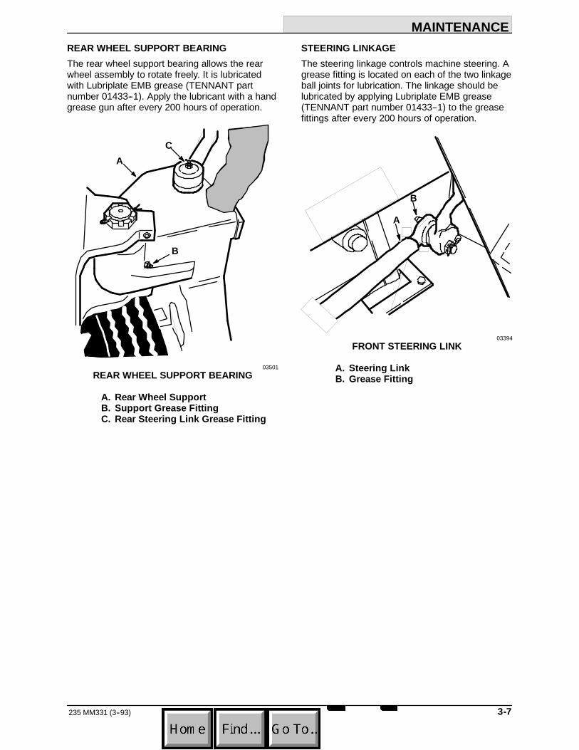
REAR WHEEL SUPPORT BEARINGThe rear wheel support bearing allows the rearwheel assembly to rotate freely. It is lubricatedwith Lubriplate EMB grease (TENNANT partnumber 01433--1). Apply the lubricant with a handgrease gun after every 200 hours of operation.
A
B
C
03501REAR WHEEL SUPPORT BEARING
A. Rear Wheel SupportB. Support Grease FittingC. Rear Steering Link Grease Fitting
STEERING LINKAGEThe steering linkage controls machine steering. Agrease fitting is located on each of the two linkageball joints for lubrication. The linkage should belubricated by applying Lubriplate EMB grease(TENNANT part number 01433--1) to the greasefittings after every 200 hours of operation.
A
B
03394FRONT STEERING LINK
A. Steering LinkB. Grease Fitting

MAINTENANCE
235 MM331 (3--94)3-8
HYDRAULICS
HYDRAULIC FLUIDThe quality and condition of the hydraulic fluidplay a very important role in how well the machineoperates. TENNANT’s hydraulic fluid is speciallyselected to meet the needs of TENNANTmachines.
TENNANT’s hydraulic fluids provide a longer lifefor the hydraulic components. There is onerecommended fluid.
TENNANT part no. Fluid Weight65870 5--20W
If a locally-available hydraulic fluid is used, makesure the specifications match TENNANT hydraulicfluid specifications. Using substitute fluids cancause premature failure of hydraulic components.
European marketed machines are filled withlocally available hydraulic fluids. Check the labelon the hydraulic fluid reservoir.
ATTENTION! Hydraulic components dependon system hydraulic fluid for internallubrication. Malfunctions, accelerated wear,and damage will result if dirt or othercontaminants enter the hydraulic system.
HYDRAULIC FLUID RESERVOIRHydraulic fluid is stored in the hydraulic fluidreservoir. It holds 3.9 gal (14.8 L) of hydraulicfluid. The reservoir is located under the seatsupport.
The fluid level is checked by looking at thedipstick on the breather-filler cap with the hopperin the sweeping position. The reservoir is fullwhen the fluid level is above the “ADD”mark onthe dipstick.
A
B
03502HYDRAULIC FLUID RESERVOIR
A. ReservoirB. Breather-Filler Cap
Check the hydraulic fluid level at operatingtemperature every 100 hours of operation.Change the hydraulic fluid after every 400 hoursof operation. Do not overfill the hydraulic fluidreservoir. Hydraulic fluid expands as it heats to itsnormal operating temperature. Always allow forexpansion when filling the reservoir. Lubricate thefiller cap gasket with a film of hydraulic fluidbefore putting the cap back on the reservoir.
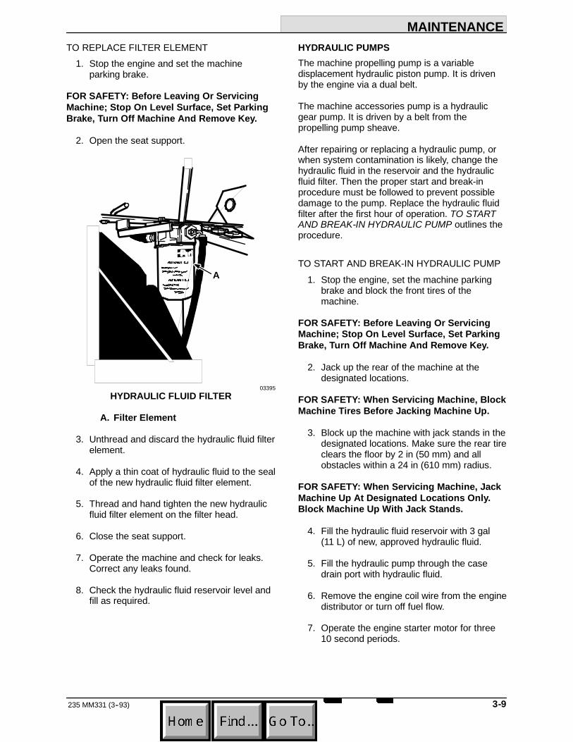
HYDRAULIC FILTERThe hydraulic fluid filter keeps the machinehydraulic system clean to a level of 10 microns.The hydraulic fluid filter is located next to thevacuum fan.
Replace the hydraulic fluid filter element after thefirst 50 hours of operation and then after every400 hours of operation.
MAINTENANCE
3-9235 MM331 (3--93)
TO REPLACE FILTER ELEMENT1. Stop the engine and set the machine
parking brake.
FOR SAFETY: Before Leaving Or ServicingMachine; Stop On Level Surface, Set ParkingBrake, Turn Off Machine And Remove Key.
2. Open the seat support.
A
03395HYDRAULIC FLUID FILTER
A. Filter Element
3. Unthread and discard the hydraulic fluid filterelement.
4. Apply a thin coat of hydraulic fluid to the sealof the new hydraulic fluid filter element.
5. Thread and hand tighten the new hydraulicfluid filter element on the filter head.
6. Close the seat support.
7. Operate the machine and check for leaks.Correct any leaks found.
8. Check the hydraulic fluid reservoir level andfill as required.
HYDRAULIC PUMPSThe machine propelling pump is a variabledisplacement hydraulic piston pump. It is drivenby the engine via a dual belt.
The machine accessories pump is a hydraulicgear pump. It is driven by a belt from thepropelling pump sheave.
After repairing or replacing a hydraulic pump, orwhen system contamination is likely, change thehydraulic fluid in the reservoir and the hydraulicfluid filter. Then the proper start and break-inprocedure must be followed to prevent possibledamage to the pump. Replace the hydraulic fluidfilter after the first hour of operation. TO STARTAND BREAK-IN HYDRAULIC PUMP outlines theprocedure.
TO START AND BREAK-IN HYDRAULIC PUMP1. Stop the engine, set the machine parking
brake and block the front tires of themachine.
FOR SAFETY: Before Leaving Or ServicingMachine; Stop On Level Surface, Set ParkingBrake, Turn Off Machine And Remove Key.
2. Jack up the rear of the machine at thedesignated locations.
FOR SAFETY: When Servicing Machine, BlockMachine Tires Before Jacking Machine Up.
3. Block up the machine with jack stands in thedesignated locations. Make sure the rear tireclears the floor by 2 in (50 mm) and allobstacles within a 24 in (610 mm) radius.
FOR SAFETY: When Servicing Machine, JackMachine Up At Designated Locations Only.Block Machine Up With Jack Stands.
4. Fill the hydraulic fluid reservoir with 3 gal(11 L) of new, approved hydraulic fluid.
5. Fill the hydraulic pump through the casedrain port with hydraulic fluid.
6. Remove the engine coil wire from the enginedistributor or turn off fuel flow.
7. Operate the engine starter motor for three10 second periods.

MAINTENANCE
235 MM331 (3--93)3-10
8. Replace the engine coil wire.
9. Start the engine and operate it at an idle fortwo minutes.
10. Press the directional pedal one-half of itstravel in the “forward”direction while alsooperating the main brush and side brush forone minute.
11. Adjust the directional pedal as described inTO ADJUST DIRECTIONAL PEDALLINKAGE.
12. Stop the engine.
13. Raise the rear of the machine, remove thejack stands, and lower the machine.
14. Fill the hydraulic fluid reservoir with new,approved hydraulic fluid.
15. Check the hose routings to be sure thehoses do not contact any moving, hot, orsharp surfaces.
16. Replace the hydraulic fluid filter after the firsthour of operation.
DIRECTIONAL PEDALThe directional pedal controls the flow of hydraulicfluid to the hydraulic drive motor. The pedal hasthree positions -- ”forward,”“neutral,”and“reverse.”The “forward”and “reverse”positionssend hydraulic fluid to the drive motor to propelthe machine.
The “neutral”position is the position in which thepropelling pump sends no hydraulic fluid to thepropelling motor. The machine should not creepwhen the “neutral”position is correctly adjusted.Adjust the pedal linkages, as described inTO ADJUST DIRECTIONAL PEDAL LINKAGE,whenever the machine creeps or after replacingthe hydraulic propelling pump or pump linkages.The pedal linkages should also be adjustedwhenever the reverse speed is excessive orinadequate.
TO ADJUST DIRECTIONAL PEDAL LINKAGE1. Stop the engine and set the machine
parking brake.
FOR SAFETY: Before Leaving Or ServicingMachine; Stop On Level Surface, Set ParkingBrake, Turn Off Machine And Remove Key.
2. Block the machine tires and jack up the rearof the machine at the designated location.
FOR SAFETY: When Servicing Machine, BlockMachine Tires Before Jacking Machine Up.
3. Block up the machine with jack stands in thedesignated locations. Make sure the rear tireclears the floor by 2 in (50 mm) and allobstacles within a 24 in (610 mm) radius.
FOR SAFETY: When Servicing Machine, JackMachine Up At Designated Locations Only.Block Machine Up With Jack Stands.
4. Loosen the two centering bolts jam nuts.
A
CB
03505CENTERING BOLTS
A. Adjustment BoltsB. Pintle ArmC. Centering Stop

MAINTENANCE
3-11235 MM331 (3--93)
5. Start the engine.
6. Move the directional pedal into the “forward”position and release it. The rear wheelshould stop rotating as soon as the pedal isreleased. Stop the engine and adjust thecentering bolt as required.
7. Move the directional pedal into the “reverse”position and release it. The rear wheelshould stop rotating as soon as the pedal isreleased. Stop the engine and adjust thecentering bolt as required.
NOTE: If there is not enough adjustment in thecentering bolts, reposition the centering stop.
8. Tighten the jam nuts.
9. Raise the rear of the machine, remove thejack stands, and lower the machine.
10. Adjust the position of the directional pedalball joints so the pedal hits the floor whenthe directional pedal is pressed backward.The backward travel should be restricted sothe machine will not travel faster than 3 mph(5 km/h) in reverse.
11. Tighten the directional pedal ball joints andjam nuts.
LIFT ARM SPEED LIMITERThe lift arm speed limiter limits the forward speedthe machine can travel when the hopper is raised.The speed limiter should be adjusted wheneverthe pump control linkage is adjusted. Themachine should travel 2 mph (3 km/h) with thehopper raised.
The speed limiter consists of a cam under thedirectional pedal with a link to the lift arms. Whenthe hopper is raised, the link lifts the cam underthe pedal. This limits how far the directional pedalcan be pressed, limiting the machine speed.
To adjust the limited speed, raise the hopper andengage the hopper support bar. Loosen the twobracket bolts and slide the bracket and camforward to increase speed or slide the bracketbackward to decrease speed. Tighten the bolts.
A
B
03507SPEED LIMITER LINK
A. Bracket and CamB. Bracket Bolts

MAINTENANCE
235 MM331 (3--93)3-12
HYDRAULIC FLUID LEAKSFluid escaping from a very small hole can bealmost invisible. Use a piece of cardboard orwood, rather than hands, to search for suspectedleaks.
A
B
C
00002HYDRAULIC PINHOLE LEAK
A. CardboardB. Pinhole LeakC. Magnifying Glass
If injured by escaping hydraulic fluid, see a doctorat once. Serious infection or reaction can developif proper medical treatment is not administeredimmediately.
FOR SAFETY: When Servicing Machine, UseCardboard To Locate Leaking Hydraulic FluidUnder Pressure.

MAINTENANCE
3-13235 MM331 (3--94)
03460HYDRAULIC SCHEMATIC
MAINTENANCE
235 MM331 (3--93)3-14
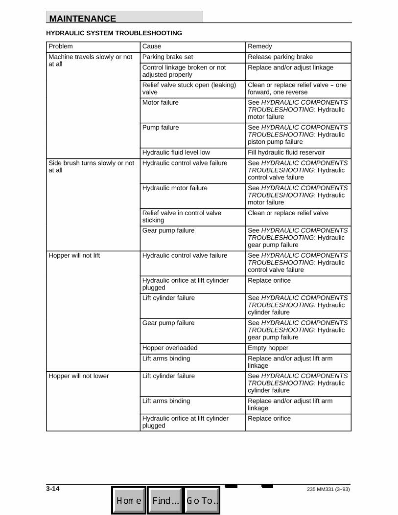
HYDRAULIC SYSTEM TROUBLESHOOTING
Problem Cause RemedyMachine travels slowly or notat all
Parking brake set Release parking brakeMachine travels slowly or notat all Control linkage broken or not
adjusted properlyReplace and/or adjust linkage
Relief valve stuck open (leaking)valve
Clean or replace relief valve -- oneforward, one reverse
Motor failure See HYDRAULIC COMPONENTSTROUBLESHOOTING: Hydraulicmotor failure
Pump failure See HYDRAULIC COMPONENTSTROUBLESHOOTING: Hydraulicpiston pump failure
Hydraulic fluid level low Fill hydraulic fluid reservoirSide brush turns slowly or notat all
Hydraulic control valve failure See HYDRAULIC COMPONENTSTROUBLESHOOTING: Hydrauliccontrol valve failure
Hydraulic motor failure See HYDRAULIC COMPONENTSTROUBLESHOOTING: Hydraulicmotor failure
Relief valve in control valvesticking
Clean or replace relief valve
Gear pump failure See HYDRAULIC COMPONENTSTROUBLESHOOTING: Hydraulicgear pump failure
Hopper will not lift Hydraulic control valve failure See HYDRAULIC COMPONENTSTROUBLESHOOTING: Hydrauliccontrol valve failure
Hydraulic orifice at lift cylinderplugged
Replace orifice
Lift cylinder failure See HYDRAULIC COMPONENTSTROUBLESHOOTING: Hydrauliccylinder failure
Gear pump failure See HYDRAULIC COMPONENTSTROUBLESHOOTING: Hydraulicgear pump failure
Hopper overloaded Empty hopperLift arms binding Replace and/or adjust lift arm
linkageHopper will not lower Lift cylinder failure See HYDRAULIC COMPONENTS
TROUBLESHOOTING: Hydrauliccylinder failure
Lift arms binding Replace and/or adjust lift armlinkage
Hydraulic orifice at lift cylinderplugged
Replace orifice

MAINTENANCE
3-15235 MM331 (3--93)
HYDRAULIC COMPONENTS TROUBLESHOOTING
Problem Cause RemedyHydraulic cylinder failure Piston seals leaking Install seal kitHydraulic cylinder failure
Barrel worn or rod bent Replace cylinder rodHydraulic control valve failure Valve seals leaking Install seal kitHydraulic control valve failure
Relief valve stuck open (leaking) Clean or replace relief valveHydraulic motor failure Motor leaking Install seal kitHydraulic motor failure
Drive link failure Replace drive linkGerotor worn Replace gerotor setOutput shaft failure Replace output shaft and bearings
Hydraulic gear pump failure Pump leaking Install seal kitHydraulic gear pump failureGear set failure Replace gear setShaft failure Replace gear set
Hydraulic piston pump failure Pump leaking Install seal kitHydraulic piston pump failureRelief valve stuck Clean or replace relief valveIntegral charge pump failure Replace charge pumpRotating group worn Replace rotating groupShaft failure Replace shaftBackplate worn Replace backplateEngine-to-pump coupling failure Replace coupling

MAINTENANCE
235 MM331 (3--93)3-16
ENGINE
ENGINE LUBRICATIONCheck the engine oil level daily.
Change the engine oil and oil filter after the first35 hours of operation and then after every75 hours of operation. Use a straight SAE20-weight, API class CD engine oil when ambienttemperatures range from 32 to 77_F (0 to 25_C).Use a straight SAE 30-weight, API class CDengine oil when ambient temperatures are above77_F (25_C). If multiviscosity oil is preferred, useSAE 10W-30 weight, API class CD engine oil forall temperatures.
The engine oil capacity is 3.2 qt (3 L).
AB
03509DIPSTICK AND FILL CAP
A. DipstickB. Fill Cap
COOLING SYSTEMMaintaining cooling system efficiency is important.Engine temperatures must be brought up to andmaintained within the satisfactory range forefficient operation. However, the engine must bekept from overheating in order to prevent damageto the valves, pistons, and bearings. Check theradiator coolant level after every 75 hours ofoperation. Fill the cooling system through thecoolant overflow tank, not through the radiator.
A
03508COOLANT TANK
A. Tank
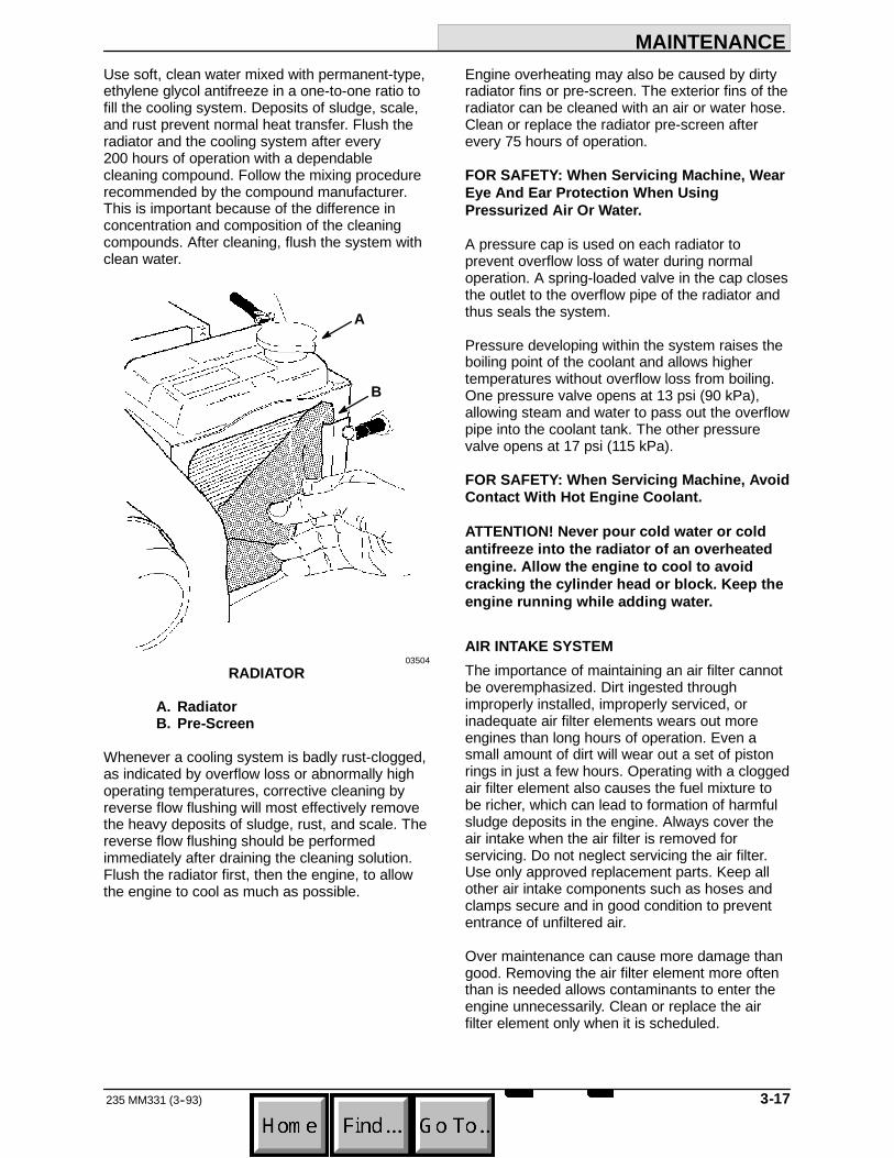
MAINTENANCE
3-17235 MM331 (3--93)
Use soft, clean water mixed with permanent-type,ethylene glycol antifreeze in a one-to-one ratio tofill the cooling system. Deposits of sludge, scale,and rust prevent normal heat transfer. Flush theradiator and the cooling system after every200 hours of operation with a dependablecleaning compound. Follow the mixing procedurerecommended by the compound manufacturer.This is important because of the difference inconcentration and composition of the cleaningcompounds. After cleaning, flush the system withclean water.
A
B
03504RADIATOR
A. RadiatorB. Pre-Screen
Whenever a cooling system is badly rust-clogged,as indicated by overflow loss or abnormally highoperating temperatures, corrective cleaning byreverse flow flushing will most effectively removethe heavy deposits of sludge, rust, and scale. Thereverse flow flushing should be performedimmediately after draining the cleaning solution.Flush the radiator first, then the engine, to allowthe engine to cool as much as possible.
Engine overheating may also be caused by dirtyradiator fins or pre-screen. The exterior fins of theradiator can be cleaned with an air or water hose.Clean or replace the radiator pre-screen afterevery 75 hours of operation.
FOR SAFETY: When Servicing Machine, WearEye And Ear Protection When UsingPressurized Air Or Water.
A pressure cap is used on each radiator toprevent overflow loss of water during normaloperation. A spring-loaded valve in the cap closesthe outlet to the overflow pipe of the radiator andthus seals the system.
Pressure developing within the system raises theboiling point of the coolant and allows highertemperatures without overflow loss from boiling.One pressure valve opens at 13 psi (90 kPa),allowing steam and water to pass out the overflowpipe into the coolant tank. The other pressurevalve opens at 17 psi (115 kPa).
FOR SAFETY: When Servicing Machine, AvoidContact With Hot Engine Coolant.
ATTENTION! Never pour cold water or coldantifreeze into the radiator of an overheatedengine. Allow the engine to cool to avoidcracking the cylinder head or block. Keep theengine running while adding water.
AIR INTAKE SYSTEMThe importance of maintaining an air filter cannotbe overemphasized. Dirt ingested throughimproperly installed, improperly serviced, orinadequate air filter elements wears out moreengines than long hours of operation. Even asmall amount of dirt will wear out a set of pistonrings in just a few hours. Operating with a cloggedair filter element also causes the fuel mixture tobe richer, which can lead to formation of harmfulsludge deposits in the engine. Always cover theair intake when the air filter is removed forservicing. Do not neglect servicing the air filter.Use only approved replacement parts. Keep allother air intake components such as hoses andclamps secure and in good condition to prevententrance of unfiltered air.
Over maintenance can cause more damage thangood. Removing the air filter element more oftenthan is needed allows contaminants to enter theengine unnecessarily. Clean or replace the airfilter element only when it is scheduled.

MAINTENANCE
235 MM331 (3--93)3-18
AIR FILTERThe engine air filter housing includes a dust capand a dry cartridge-type air filter element. Thedust cap must be emptied of dirt daily. The airfilter element must be cleaned and inspected orreplaced after every 100 hours of operation. Thefilter element must be replaced if it is damaged orhas been cleaned three times.
TO REPLACE AIR FILTER ELEMENT1. Stop the engine and set the machine
parking brake.
FOR SAFETY: Before Leaving Or ServicingMachine; Stop On Level Surface, Set ParkingBrake, Turn Off Machine And Remove Key.
2. Open the seat support.
3. Unlatch and remove the dust cap.
4. Empty the dust cap.
5. Remove the filter wing nut.
6. Gently pull the filter element out of the filterhousing.
A
B03493
REMOVING AIR FILTER ELEMENT
A. Filter HousingB. Filter Element
7. Clean the interior of the air cleaner housingwith a damp cloth. Clean the elementhousing sealing surfaces.
8. Using an air hose, direct dry, clean airmaximum 30 psi (205 kPa) up and downpleats on the inside of the filter. Do not rap,tap, or pound dust out of the element.
FOR SAFETY: When Servicing Machine, WearEye And Ear Protection When UsingPressurized Air Or Water.
B
A
00051CLEANING AIR FILTER ELEMENT
A. Air HoseB. Filter Element
9. After cleaning the air filter element, inspect itfor damage by placing a bright light inside.The slightest rupture requires replacementof the filter. Clean and inspect the ends ofthe element. They should be unbroken andflexible. Remember, the element must bereplaced after it has been cleaned threetimes.
A
B
03500INSPECTING AIR FILTER ELEMENT
A. Bright LightB. Filter Element

MAINTENANCE
3-19235 MM331 (3--93)
10. Install the new or cleaned filter element sothe fins on the element are at the intake endof the air cleaner. Use care so the fins arenot damaged. Tighten the wing nut attachingthe element.
11. Install the dust cap with the tab down.Secure the cap with the latches. Check allintake hose connections for leaks orabrasion.
B
C
A
03484DUST CAP
A. Dust CapB. TabC. Housing
12. Close the seat support.
FUEL SYSTEM
FUEL SYSTEMThe diesel fuel system is made up of five basiccomponents which are: fuel tank, fuel water trapfilter, fuel pump, injection pump, and injectors.
Fuel flows from the fuel tank through the fuelwater trap filter. The water trap filter separateswater and impurities from the fuel. From the fuelwater trap filter, fuel is drawn through the electricfuel pump and pumped to the injection pump. Theinjection pump pressurizes and sends fuel to theinjectors. The injectors atomize and inject properamounts of fuel into the combustion chamber atthe proper times. Excess fuel is returned to thefuel tank through an overflow pipe.
FUEL WATER TRAP FILTERThe fuel water trap filter separates water andimpurities from the fuel. It is located next to thefuel tank. The bottom portion of the unit is thewater trap. The middle portion is the filterelement.
Drain the water trap of water daily. To drain thewater trap, loosen the drain knob on the bottom ofthe unit. First water, then diesel fuel will drain.Tighten the drain knob when diesel fuel appears.
Replace the fuel filter element and clean the watertrap after every 400 hours of operation.
TO REPLACE FUEL FILTER ELEMENT1. Stop the engine and set the machine
parking brake.
FOR SAFETY: Before Leaving Or ServicingMachine; Stop On Level Surface, Set ParkingBrake, Turn Off Machine And Remove Key.
2. Open the seat support.
3. Close the fuel drain cock.
4. Loosen the water trap vent plug and openthe drain valve to drain diesel fuel.
A
C
D
B
E
03494FUEL WATER TRAP FILTER
A. Filter HeadB. Vent PlugC. Filter ElementD. Water Trap BowlE. Fuel Drain Cock

MAINTENANCE
235 MM331 (3--93)3-20
5. Remove the filter element and the water trapfrom the filter head.
6. Remove the water trap bowl from the filterelement.
7. Clean the water trap bowl.
8. Lubricate the o-ring and spin the water trapbowl onto the new filter element.
9. Lubricate the o-ring and spin the filterelement and water trap onto the filter head.
10. Open the fuel drain cock.
11. Bleed the fuel lines of air as described in TOPRIME FUEL SYSTEM.
12. Close the seat support.
PRIMING FUEL SYSTEMPriming the fuel system removes pockets of air inthe fuel lines and fuel components. Air in the fuelsystem will prevent smooth engine operation.
Prime the fuel system after running out of fuel,changing fuel filter elements or repairing a fuelsystem component.
TO PRIME FUEL SYSTEM1. Stop the engine and set the machine
parking brake.
FOR SAFETY: Before Leaving Or ServicingMachine; Stop On Level Surface, Set ParkingBrake, Turn Off Machine And Remove Key.
2. Fill the fuel tank.
3. Open the seat support.
4. Open the air vent on top of the fuel injectionpump.
B
A
03482FUEL INJECTION PUMP
A. Injection PumpB. Air Vent
5. Turn the ignition switch to the “ON”position(this operates the electric fuel pump) until asteady stream of fuel flows from the vent.
6. Close the air vent.
7. Close the seat support.

MAINTENANCE
3-21235 MM331 (3--93)
DIESEL FUEL TROUBLESHOOTING
Problem Cause RemedyEngine will not start Out of fuel Fill fuel tankEngine will not start
Filter plugged Clean filterAir in fuel Bleed fuel linesWater in fuel Drain water trapFuel too thick Change fuel gradeBattery discharged Charge or replace batteryClogged fuel nozzle Clean or replace nozzleValve clearance wrong Adjust valvesLeaking valves Grind valvesTiming wrong Adjust timingLow compression Repair engine
Engine runs unevenly or lackspower
Dirty air filter Clean or replace filterEngine runs unevenly or lackspower Plugged fuel filter Clean filter
Water in fuel Drain water trapFuel too thick Change fuel gradeClogged fuel nozzle Clean or replace nozzleLow compression Repair engineEngine overheating Check radiatorEngine overheating
Check lubricating systemTiming wrong Check timingValve clearance wrong Adjust valvesFuel pressure wrong Adjust pressureInjection pump worn Repair or replace pump
Engine stops suddenly Fuel leak Check fuel systemEngine stops suddenlyOut of fuel Fill fuel tankFuel nozzle bad Replace nozzleEngine overheating Check radiatorEngine overheating
Check lubricating systemTiming wrong Check timing
Exhaust color bad Fuel governor failure Repair or replaceExhaust color badBad fuel Change fuel gradeFuel nozzle bad Replace nozzleTiming wrong Check timingLow compression Repair engineValve clearance wrong Adjust valvesInjection pump worn Repair or replace pump

MAINTENANCE
235 MM331 (3--93)3-22
CYLINDER HEAD
CYLINDER HEADThe cylinder head must be properly torqued afterservicing to ensure proper operation. A three-stage torque procedure should be used. Snugdown the cylinder head bolts and nuts in theproper sequence; first to one-third, thentwo-thirds, and then to the full torque specificationof 42 to 45 ft lb (55 to 60 Nm). Retighten the boltsand nuts after operating the engine for30 minutes.
NOTE: Power wrench torque limit must be held atleast 10 ft lb (15 Nm) below torque specification.Hand tighten to specification.
10 4 2 5 8
93
16
7
03483CYLINDER HEAD BOLT TIGHTENING
SEQUENCE
VALVE CLEARANCEThe valve clearance must be properly adjustedafter servicing or retorquing the cylinder headbolts to ensure proper operation. Measure valveclearance with a feeler gauge after aligning eachcylinder on the compression top dead centerstroke.
Adjust them with the engine cool to 0.0057 to0.0073 in (0.14 to 0.18 mm).
DECOMPRESSION LEVERThe decompression lever was available on earlierstyle engines. The lever allows the release ofsome compression pressure from the cylinders.This is useful when the battery is weak, when theengine has not been run for a long period of time,and when the engine is in a cold ambienttemperature.
To engage, push the lever down while crankingthe engine. Then release the lever to engage theinjection system. Do not touch the lever when theengine is operating or the engine valve systemmay be damaged. Do not press the lever whenthe engine is not turning over or it may be bedifficult or impossible to start.
AB
03492DECOMPRESSION LEVER
A. LeverB. Injection Pump

MAINTENANCE
3-23235 MM331 (3--93)
ELECTRICAL SYSTEM
BATTERYThe battery used in this machine is rated at 12 V,330 ccA. It is located in the front left of themachine behind the hopper. When removingbattery cables, remove the negative (--) cablebefore the positive (+) cable.
Clean the top surface and the terminals of thebattery periodically. Use a strong solution ofbaking soda and water. Brush the solutionsparingly over the battery top, terminals, andcable clamps. Do not allow any baking sodasolution to enter the battery. Use a wire brush toclean the terminal posts and the cableconnectors. After cleaning, apply a coating ofclear petroleum jelly to the terminals and thecable connectors. Keep the top of the batteryclean and dry.
Keep all metallic objects off the top of the battery,as they may cause a short circuit. Replace wornor damaged wires.
The electrolyte level in regular nonsealedbatteries can be checked. It must always beabove the battery plates. Add distilled water tomaintain solution at the correct level above theplates, but do not overfill. Never add acid tobatteries, only water. Keep vent plugs firmly inplace at all times, except when adding water ortaking hydrometer readings.
FOR SAFETY: When Servicing Machine, AvoidContact With Battery Acid.
If when checking battery specific gravity, one ormore battery cells tests lower than the otherbattery cells, (0.050 or more) the cell is damaged,shorted, or is about to fail.
NOTE: Do not take readings immediately afteradding water----if the water and acid are notthoroughly mixed, the readings may not beaccurate. Check the hydrometer readings againstthis chart:
SPECIFIC GRAVITY BATTERYAT 80_F (27_C) CONDITION
1.265 100% charged1.225 75% charged1.190 50% charged1.155 25% charged1.120 Discharged
NOTE: If the readings are taken when the batteryelectrolyte is any temperature other than 80_F(27_C), the reading must be temperaturecorrected.
To determine the corrected specific gravityreading when the temperature of the batteryelectrolyte is other than 80_F (27_C):
Add to the specific gravity reading 0.004(4 points) for each 10_F (6_C) above80_F (27_C).
Subtract from the specific gravity reading0.004 (4 points) for each 10_F (6_C) below80_F (27_C).

MAINTENANCE
235 MM331 (3--94)3-24
03490ELECTRICAL SCHEMATIC

MAINTENANCE
3-25235 MM331 (3--94)
03490ELECTRICAL SCHEMATIC, AUXILIARY SIDE BRUSH

MAINTENANCE
235 MM331 (3--94)3-26
BELTS AND CHAINS
HYDRAULIC PUMP BELTThe hydraulic pump belt transfers power from theengine sheave to the hydraulic pump. Check beltcondition and tension after every 200 hours ofoperation. The belt is properly tensioned when itdeflects 0.26 in (7 mm) from a force of 7 lb(3 kg) applied at belt midpoint.
TO REPLACE AND ADJUST HYDRAULIC PUMPBELT
1. Stop the engine and set the machineparking brake.
FOR SAFETY: Before Leaving Or ServicingMachine; Stop On Level Surface, Set ParkingBrake, Turn Off Machine And Remove Key.
2. Open the seat support.
3. Remove the vacuum fan and engine beltguards.
4. Loosen the pump plate mounting andadjustment bolts.
D
B
A
C
03498HYDRAULIC PUMP
A. Hydraulic PumpB. Pump PlateC. Adjustment BoltsD. Mounting Bolts
5. Slide the pump assembly backward toremove the belt. Position the new pump belton the sheaves.
6. Push the pump forward keeping the sheavesaligned and snug the mounting bolts.
7. Check belt tension. If it meets specification,tighten the bolts. If not, repeat the steps.
A04233
CHECKING BELT TENSION
A. Hydraulic Pump Belt
8. Replace belt guards.
9. Lower the seat support.
VACUUM FAN BELTThe vacuum fan belt transfers power from thepump sheave to the vacuum fan and theaccessories pump. Check the belt condition andtension after every 200 hours of operation. Thebelt is properly tensioned when the belt deflects0.25 in (6 mm) from a force of 6 lb (3 kg) appliedat belt midpoint.
TO REPLACE AND ADJUST VACUUM FANBELT
1. Stop the engine and set the machineparking brake.
FOR SAFETY: Before Leaving Or ServicingMachine; Stop On Level Surface, Set ParkingBrake, Turn Off Machine And Remove Key.
2. Open the seat support.

MAINTENANCE
3-27235 MM331 (3--94)
3. Remove the vacuum fan belt guard.
C
AB
04322VACUUM FAN BELT GUARD
A. TurnbuckleB. Vacuum FanC. Belt Guard
4. Loosen the pump plate mounting andadjustment bolts.
D
B
C
A
03498HYDRAULIC PUMP
A. Hydraulic PumpB. Pump PlateC. Adjustment BoltsD. Mounting Bolts
5. Slide the pump assembly backward toremove the belts.
6. Replace the existing vacuum fan belt with anew belt.
AB
03499BELTS
A. Vacuum Fan BeltB. Pump Belt
7. Position the pump belt on the sheaves.
8. Push the pump forward keeping the sheavesaligned and snug the mounting bolts.
9. Tighten the pump belt as described in TOREPLACE AND ADJUST HYDRAULICPUMP BELT.
10. Turn the turnbuckle to tighten the vacuumfan belt to specification.
A
04234CHECKING BELT TENSION
A. Vacuum Fan Belt

MAINTENANCE
235 MM331 (3--94)3-28
11. Replace the belt guard.
12. Lower the seat support.
MAIN BRUSH BELTThe main brush belt transfers power from theaccessories pump to the main brush. The belt istensioned by a belt idler spring. A stop bolt isused to remove tension from the belt when themain brush is raised.
TO REPLACE MAIN BRUSH BELT1. Stop the engine and set the machine
parking brake.
FOR SAFETY: Before Leaving Or ServicingMachine; Stop On Level Surface, Set ParkingBrake, Turn Off Machine And Remove Key.
2. Raise the main brush.
3. Open the seat support.
4. Remove the vacuum fan belt guard.
5. Remove the left side access door.
6. Hold the idler spring arm back and removethe belt.
A
C
B
03377MAIN BRUSH BELT
A. Idler Spring ArmB. Main Brush BeltC. Stop Bolt
7. Position the new belt on the belt sheaves.
8. Replace the vacuum fan belt guard.
9. Lower the seat support.
10. Start the machine and lower the main brush.Then raise the brush. The brush should stopturning within seconds of being raised. If thebelt is too tight, the brush will continue toturn. If the belt is too loose, it may jump offthe idler or driven sheave. Turn the belt stopbolt to adjust belt tension.
11. Replace the left side access door.
FAN BELTThe fan belt is driven by the crankshaft sheaveand drives the alternator and the radiator fan.Check the belt condition and tension after every200 hours of operation. The belt is properlytensioned when the belt deflects 0.28 in (7 mm)from a force of 22 lb (10 kg) applied at beltmidpoint.
TO REPLACE AND ADJUST FAN BELT1. Stop the engine and set the machine
parking brake.
FOR SAFETY: Before Leaving Or ServicingMachine; Stop On Level Surface, Set ParkingBrake, Turn Off Machine And Remove Key.
2. Open the seat support.

MAINTENANCE
3-29235 MM331 (3--94)
3. Remove the vacuum fan and engine beltguards.
BC
A
D
03503FAN BELT
A. Fan BeltB. AlternatorC. Mounting BoltD. Engine Belt Guard
4. Loosen the pump plate mounting andadjustment bolts.
D
B
C
A
03498HYDRAULIC PUMP
A. Hydraulic PumpB. Pump PlateC. Adjustment BoltsD. Mounting Bolts
5. Slide the pump assembly backward toremove the belt.
6. Loosen the alternator mounting bolts.
7. Replace the fan belt.
8. Tighten the fan belt to specification.
A
B C04235
CHECKING BELT TENSION
A. Engine Fan BeltB. AlternatorC. Mounting Bolt
9. Position the hydraulic pump belts back onthe sheaves.
10. Push the pump forward keeping the sheavesaligned and snug the mounting bolts.
11. Tighten the pump belt as described in TOREPLACE AND ADJUST HYDRAULICPUMP BELT.
12. Replace the belt guards.
13. Lower the seat support.

MAINTENANCE
235 MM331 (3--94)3-30
TAPER LOCK BUSHINGSTaper lock bushings are used to secure thesheaves on the engine and propelling pumpshafts.
TO REMOVE TAPER LOCK BUSHING1. Remove all set screws.
2. Insert a set screw into the threaded hole ofthe bushing.
B
CD
A
03506TAPER LOCK BUSHING
A. Set ScrewB. HubC. BushingD. Threaded Hole
3. Tighten the set screw to loosen bushingfrom shaft.
TO INSTALL TAPER LOCK BUSHING1. Clean shaft, bore and outside of bushing
and hub bore of all oil, lacquer, and dirt.
2. Insert bushing into hub; be aware of sheavealignment. Match hole pattern, not threadedholes. Each hole will be threaded on oneside only.
3. Oil set screws. Thread them into the halfthreaded holes.
4. Alternately tighten the set screws to175 in lb (20 Nm).
5. Using a block, sleeve, or drift, hammer theend of the bushing. Do not hammer bushingdirectly.
6. Repeat steps 4 and 5 until torque wrenchreading is the same after hammering asbefore.
7. Fill all open holes with grease.
STATIC DRAG CHAINThe static drag chain prevents the buildup ofstatic electricity in the machine. The chain isattached to the rear skirt retaining strip.
Make sure that the chain is making contact withthe floor at all times.
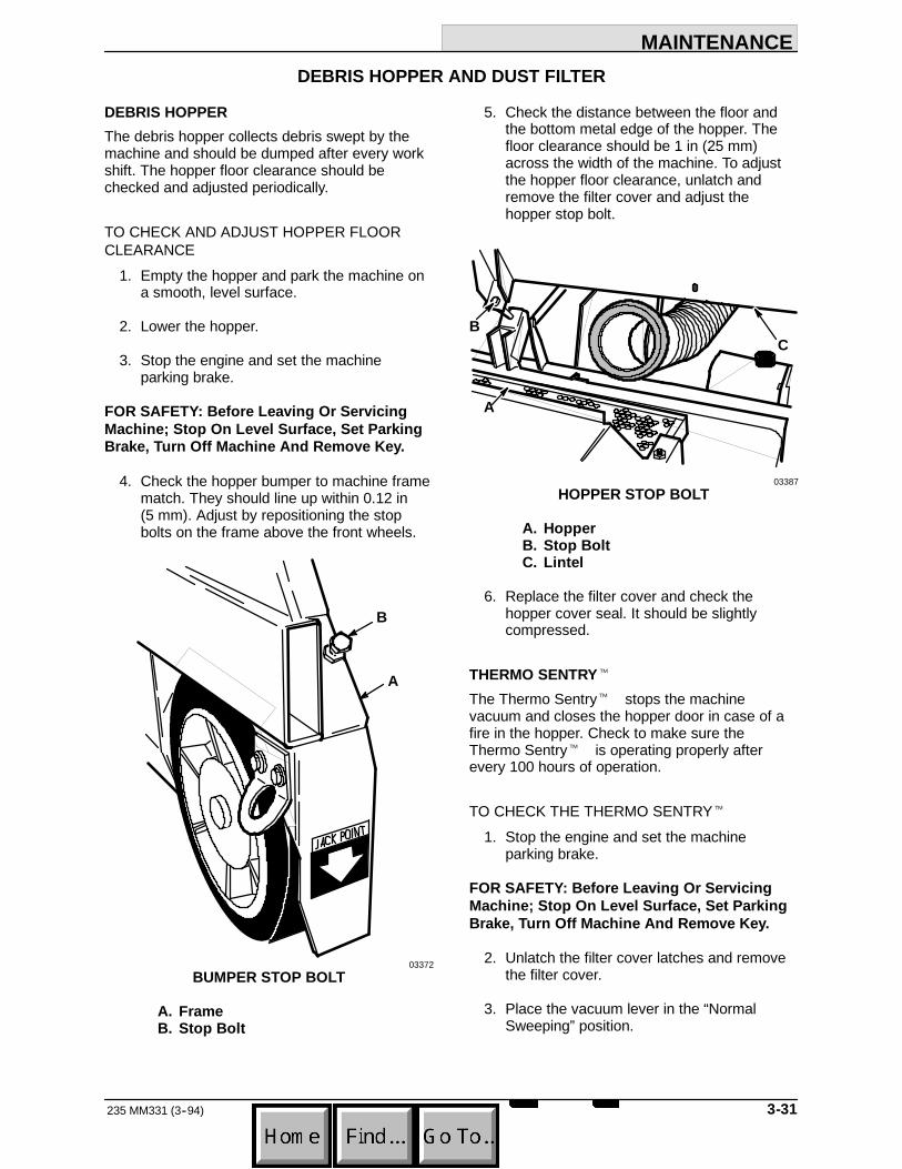
MAINTENANCE
3-31235 MM331 (3--94)
DEBRIS HOPPER AND DUST FILTER
DEBRIS HOPPERThe debris hopper collects debris swept by themachine and should be dumped after every workshift. The hopper floor clearance should bechecked and adjusted periodically.
TO CHECK AND ADJUST HOPPER FLOORCLEARANCE
1. Empty the hopper and park the machine ona smooth, level surface.
2. Lower the hopper.
3. Stop the engine and set the machineparking brake.
FOR SAFETY: Before Leaving Or ServicingMachine; Stop On Level Surface, Set ParkingBrake, Turn Off Machine And Remove Key.
4. Check the hopper bumper to machine framematch. They should line up within 0.12 in(5 mm). Adjust by repositioning the stopbolts on the frame above the front wheels.
B
A
03372BUMPER STOP BOLT
A. FrameB. Stop Bolt
5. Check the distance between the floor andthe bottom metal edge of the hopper. Thefloor clearance should be 1 in (25 mm)across the width of the machine. To adjustthe hopper floor clearance, unlatch andremove the filter cover and adjust thehopper stop bolt.
B
A
C
03387HOPPER STOP BOLT
A. HopperB. Stop BoltC. Lintel
6. Replace the filter cover and check thehopper cover seal. It should be slightlycompressed.
THERMO SENTRYt
The Thermo Sentryt stops the machinevacuum and closes the hopper door in case of afire in the hopper. Check to make sure theThermo Sentryt is operating properly afterevery 100 hours of operation.
TO CHECK THE THERMO SENTRYt
1. Stop the engine and set the machineparking brake.
FOR SAFETY: Before Leaving Or ServicingMachine; Stop On Level Surface, Set ParkingBrake, Turn Off Machine And Remove Key.
2. Unlatch the filter cover latches and removethe filter cover.
3. Place the vacuum lever in the “NormalSweeping”position.

MAINTENANCE
235 MM331 (3--94)3-32
4. Apply heat to the bottom of the ThermoSentryt with a match or lighter. Thevacuum lever should move to the “WetSweeping”position, the hopper door shouldclose, and their circuit breakers should trip.If they do not, the system is malfunctioning.
A
B
03393THERMO SENTRYt
A. Thermo SentrytB. Shaker Motor
5. Replace the filter cover and check thehopper cover seal. It should be slightlycompressed.
6. After the Thermo Sentryt has cooled,reset the circuit breakers behind the controlpanel.
HOPPER DUST FILTERThe hopper dust filter filters the air which is drawnup from the main brush compartment by thevacuum fan. It is located inside the dust filtercompartment. Shake the excess dust from thefilter daily. Inspect and clean or replace the dustfilter after every 100 hours of operation.
To clean the dust filter use one of the followingmethods:
D TAPPING -- Tap the filter gently on a flatsurface with the dirty side down. Do notdamage the edges of the filter element orthe filter will not seat properly in the filterframe.
D AIR -- Blow compressed air, 35 psi (240kPa) maximum, through the dust filteropposite the direction of the arrows. Thismay be done with the filter in the machine.Always wear eye protection when usingcompressed air.
FOR SAFETY: When Servicing Machine, WearEye And Ear Protection When UsingPressurized Air Or Water.
D WATER -- Soak the dust filter in a water andmild detergent solution. Rinse the dust filteruntil it is clean. The maximum waterpressure allowable is 40 psi (275 kPa). Airdry the wet filter; do not use compressed air.
NOTE: Be sure the dust filter is dry beforereinstalling it in the machine.

MAINTENANCE
3-33235 MM331 (3--94)
TO REMOVE AND REPLACE HOPPER DUSTFILTER
1. Stop the engine and set the machineparking brake.
FOR SAFETY: Before Leaving Or ServicingMachine; Stop On Level Surface, Set ParkingBrake, Turn Off Machine And Remove Key.
2. Unlatch the two filter cover latches andremove the filter cover.
3. Remove the two assembly bolts on eachside of the filter and slide the assemblyback. Remove the dust filter.
A
B
D
C
03389DUST FILTER
A. Dust FilterB. Shaker Motor AssemblyC. Hold-Down ScrewsD. Assembly Bolts
4. Inspect and clean or replace the dust filter.
5. Position the dust filter in the filter frame withthe arrows on the label pointing up.
6. Secure the filter with the shaker motorassembly.
7. Check the two filter hold-down screws. Theyshould clear the filter by 0.03 in (1 mm).
8. Secure the filter cover on the filter framewith the two latches.
9. Check the hopper cover seal. It should beslightly compressed.

MAINTENANCE
235 MM331 (3--94)3-34
BRUSHES
MAIN BRUSHThe main brush is tubular and spans the width ofthe machine, sweeping debris into the debrishopper. The brush should be inspected daily forwear or damage. Remove any string or wire foundtangled on the main brush, main brush drive hub,or main brush idler hub.
Rotate the main brush end-for-end after every50 hours of operation for maximum brush life andbest sweeping performance. Check the mainbrush pattern whenever installing a new brush.
The main brush should be replaced when theremaining bristles measure 1.5 in (40 mm) or lessin length.
TO REMOVE MAIN BRUSH1. Stop engine and set the machine parking
brake.
FOR SAFETY: Before Leaving Or ServicingMachine; Stop On Level Surface, Set ParkingBrake, Turn Off Machine And Remove Key.
2. Lower the main brush.
3. Remove the right side access door.
4. Remove the brush idler arm retaining boltfrom the arm hub.
B
A
C
D
03390MAIN BRUSH IDLER ARM
A. Brush Idler ArmB. Arm Retaining BoltC. Main BrushD. Threaded Hole
5. Pull the brush idler arm off the arm hub.
NOTE: If the brush idler arm does not come offeasily, thread the retaining bolt into the threadedhole on the arm. Tighten the bolt until it is tightagainst the backing plate. Push on the brush endof the arm and retighten the bolt. Repeat until thearm is loose.
6. Grasp the main brush, pull it off the brushdrive plug, and out of the main brushcompartment.
TO INSTALL MAIN BRUSH1. Push the main brush lever into the “UP”
position.
2. Slide the main brush into the main brushcompartment.
3. Align the main brush drive slots with thedrive keys on the main brush drive plug.
4. Slide the main brush onto the drive plug.Make sure the drive slots and keys mate.
5. Align the main brush idler plug slots with themain brush keys. Slide the main brush idlerplug into the main brush tube.
6. Slide the brush idler arm onto the arm hub.
7. Thread the brush idler arm retaining boltthrough the idler arm and into the arm hub.
8. Tighten the brush idler arm retaining bolt.
9. Replace the right side access door.
TO CHECK AND ADJUST MAIN BRUSHPATTERN
1. Apply chalk, or some other material that willnot blow away easily, to a smooth, levelfloor.
2. With the side brush and main brush raised,position the main brush over the chalkedarea.
3. While keeping a foot on the brakes to keepthe machine from moving, lower the mainbrush to the floor for 15 to 20 seconds; raisethe main brush and drive the machine off thetest area.

MAINTENANCE
3-35235 MM331 (3--94)
NOTE: If no chalk or other material is available,allow the brushes to spin on the floor for twominutes.
4. Observe the brush pattern made. Thepattern should be of equal width across thelength of the pattern.
A
B
00582NORMAL MAIN BRUSH PATTERN
A. Main Brush PatternB. 2 to 2.5 in (51 to 54 mm) for
machines serial number 002594and above
For machines serial number 002594 andabove, and machines with the Brush LimiterKit installed, the brush pattern width shouldbe 2 to 2.5 in (51 to 54 mm). The brushpattern width can be adjusted by looseningand moving the brush limiter nut.
A
B
03487BRUSH LIMITER NUT (For machines serial
number 002594 and above)
A. Brush Limiter NutB. Main Brush Lever Slot
To decrease the width of the brush pattern,move the limiter nut forward and tighten thenut. To increase the brush pattern width,move the limiter nut back and tighten thenut.
If the main brush pattern is tapered, wideron one side by 0.50 in (15 mm) or more thanthe other side, perform the following levelingprocedure:
00601TAPERED MAIN BRUSH PATTERN
A. Park the machine on a level surface.
B. Stop the engine and set the machineparking brake.
FOR SAFETY: Before Leaving Or ServicingMachine; Stop On Level Surface, Set ParkingBrake, Turn Off Machine And Remove Key.
C. Lower the main brush.
D. Remove the right side access door.
E. Remove the main brush.
F. Reinstall the idler arm.
G. Loosen the cross shaft bearing flangebolts.
A
C
B
03550CROSS SHAFT BEARING FLANGE
A. FlangeB. BoltsC. Cross Shaft

MAINTENANCE
235 MM331 (3--94)3-36
H. Position the idler plug so it is the samedistance from the floor as the drive plugand tighten the bolts.
I. Reinstall the main brush.
J. Recheck the main brush pattern.
K. Replace the right side access door.
SIDE BRUSHThe side brush sweeps debris from curbs orgutters into the path of the main brush. The sidebrush should be inspected daily for wear ordamage. Remove any string or wire found tangledon the side brush or side brush drive hub.
The side brush pattern should be checkedperiodically. One-third of the side brush bristlesshould contact the floor when the brush is inmotion. The side brush pattern adjustment ismade by turning the side brush adjustment knobon the front bumper.
The side brush should be replaced when theremaining brush bristle measures 2.5 in (65 mm)in length.
TO REMOVE SIDE BRUSH1. Raise the hopper.
2. Engage the hopper support bar.
WARNING: Falling Hopper. EngageHopper Support Bar. Read Manual.
3. Stop the engine and set the machineparking brake.
FOR SAFETY: Before Leaving Or ServicingMachine; Stop On Level Surface, Set ParkingBrake, Turn Off Machine And Remove Key.
4. Raise the side brush.
5. Remove the four side brush retaining boltsfrom the bottom of the side brush.
A
B
03392SIDE BRUSH
A. Side BrushB. Retaining Bolts
6. Slide the side brush off the side brush hub.
TO INSTALL SIDE BRUSH1. Position the side brush on the side brush
drive hub.
2. Secure the side brush to the hub with thefour bolts removed earlier.
3. Check the side brush pattern. Adjust thepattern with the side brush adjustment knob.
A
03376SIDE BRUSH PATTERN
A. Contact Area

MAINTENANCE
3-37235 MM331 (3--94)
SKIRTS AND SEALS
BRUSH SKIRTSBrush skirts control main brush dusting. They arelocated on each of the brush access doors. Theskirts should be inspected for wear or damagedaily. They should clear the floor by 0 to 0.12 in (0to 5 mm) at all times.
TO REPLACE AND ADJUST BRUSH SKIRTS1. Park the machine on a smooth, level floor.
2. Stop the engine and set the machineparking brake.
FOR SAFETY: Before Leaving Or ServicingMachine; Stop On Level Surface, Set ParkingBrake, Turn Off Machine And Remove Key.
3. Remove the side access doors.
4. Replace or loosen the skirt and retainingstrip bolts. Adjust the skirt height andretighten the retaining strip bolts.
A
B03388
RIGHT SIDE BRUSH SKIRT
A. Retaining StripB. Brush Skirt
5. Replace the doors.
6. Check the skirt clearance.
REAR SKIRTSThe rear skirts seal the brush compartment. Theyare located on the bottom rear of the brushcompartment. The seals should be inspected forwear or damage daily.
TO REPLACE AND ADJUST REAR SKIRTS1. Park the machine on a smooth, level
surface.
2. Stop the engine and set the machineparking brake.
FOR SAFETY: Before Leaving Or ServicingMachine; Stop On Level Surface, Set ParkingBrake, Turn Off Machine And Remove Key.
3. Remove the side access doors.
4. Remove the rear skirt retaining strips andthe rear skirts.
AB
C
03390REAR SKIRTS
A. Brush SkirtB. Vertical Rear SkirtC. Retaining Strip
5. Loosely install new skirts with the existingretaining strips.
6. Slide the vertical rear skirt up or down so itis 0 to 0.12 in (0 to 5 mm) above the floor.
7. Retighten the retaining strip bolts.

MAINTENANCE
235 MM331 (3--94)3-38
HOPPER LIP SKIRTThe hopper lip skirt floats over debris and helpsdeflect the debris into the hopper. It is located onthe bottom rear of the hopper.
The hopper lip skirt should be inspected for wearor damage daily.
TO REPLACE HOPPER LIP SKIRT1. Empty the machine debris hopper.
2. Raise the hopper.
3. Engage the hopper support bar.
WARNING: Falling Hopper. EngageHopper Support Bar. Read Manual.
4. Stop the machine on a level surface, stopthe engine, and set the machine parkingbrake.
FOR SAFETY: Before Leaving Or ServicingMachine; Stop On Level Surface, Set ParkingBrake, Turn Off Machine And Remove Key.
5. Remove the skirt retaining strip and theskirt.
A
B
C
03384HOPPER LIP SKIRT
A. HopperB. Lip SkirtC. Retaining Strip
6. Position the new skirt on the hopper. Secureit with the retaining strip.
7. Raise the hopper, position the hoppersupport bar in its storage location, and lowerthe hopper.
DUST SEALSThree seals control hopper dusting. They are thetop, left and right side hopper seals. They shouldbe inspected for wear or damage after every100 hours of operation.
TO REPLACE DUST SEALS1. Empty the debris hopper.
2. Raise the hopper.
3. Engage the hopper support bar.
WARNING: Falling Hopper. EngageHopper Support Bar. Read Manual.
4. Stop the engine and set the machineparking brake.
FOR SAFETY: Before Leaving Or ServicingMachine; Stop On Level Surface, Set ParkingBrake, Turn Off Machine And Remove Key.
5. Remove the side access doors to gainaccess to the side seals.

MAINTENANCE
3-39235 MM331 (3--94)
6. Remove the retaining strip of the seal to bereplaced.
B
A
03369HOPPER SEALS
A. Top Hopper SealB. Side Hopper Seal
7. Remove the existing seal or skirt.
8. Mount the new seal or skirt to the machinewith the retaining strip removed earlier.
9. Replace the side access doors if removed.
10. Raise the hopper, place the hopper supportbar in its storage position, and lower thehopper.
HOPPER DUMP DOOR SEALThe hopper dump door seal allows the hopper tobe high dumped without scattering debris. Checkthe seal for damage after every 100 hours ofoperation.
TO REPLACE HOPPER DUMP DOOR SEAL1. Empty the debris hopper.
2. Raise the hopper.
3. Engage the hopper support bar.
WARNING: Falling Hopper. EngageHopper Support Bar. Read Manual.
4. Stop the engine and set the machineparking brake.
FOR SAFETY: Before Leaving Or ServicingMachine; Stop On Level Surface, Set ParkingBrake, Turn Off Machine And Remove Key.
5. Open the dump door.
6. Remove the seal retaining strip.
A
B03384
HOPPER DUMP DOOR SEAL
A. HopperB. Dump Door Seal
7. Remove the seal.
8. Mount the new seal to the door with thesponge core and retaining strip removedearlier.
9. Raise the hopper, position the hoppersupport bar in its storage position, and lowerthe hopper.

MAINTENANCE
235 MM331 (3--94)3-40
VACUUM FAN SEALThe vacuum fan seal seals the vacuum fan to thefilter cover. Check the seal for damage after every100 hours of operation.
A
03387VACUUM FAN SEAL
A. Vacuum Fan Seal
FILTER COVER SEALThe filter cover seal seals the filter box to the filtercover. Check the seal for damage after every100 hours of operation.
A B
03375FILTER COVER SEAL
A. Filter CoverB. Seal

MAINTENANCE
3-41235 MM331 (8--95)
BRAKES AND TIRES
BRAKESThe foot brake and the parking brake operate thelinkage which controls the brakes on the frontwheels.
The foot brake needs no regular adjustment. Theparking brake should be adjusted after every200 hours of operation or whenever it becomesvery easy to set.
To adjust the parking brake, turn the knurled knobon the end of the parking brake clockwise. If theknob adjustment is inadequate, remove the clevispin from each brake assembly, turn the clevisends an equal amount, reconnect the clevis pins,and readjust the parking brake.
BA
03369BRAKE ASSEMBLY
A. ClevisB. Brake Rod
TIRESThe front machine tires are solid. The rear tire ispneumatic. Proper air pressure is 90 psi(620 kPa). They should be inspected for wearafter every 100 hours of operation.
REAR WHEELTorque the rear wheel nuts in a star pattern to122 to 150 Nm (90 to 110 ft lb) after the first50-hours of operation, and every 800 hours thereafter.

MAINTENANCE
235 MM331 (3--94)3-42

APPENDIX
4-1235 MM331 (3--93)
SECTION 4CONTENTS
PageHARDWARE INFORMATION 4-3. . . . . . . . . . . .
STANDARD BOLT TORQUE CHART 4-3. .METRIC BOLT TORQUE CHART 4-3. . . . .BOLT IDENTIFICATION 4-3. . . . . . . . . . . . . .THREAD SEALANT AND LOCKING
COMPOUNDS 4-3. . . . . . . . . . . . . . . . . . .HYDRAULIC FITTING INFORMATION 4-4. . . .
HYDRAULIC TAPERED PIPE FITTING(NPT) TORQUE CHART 4-4. . . . . . . . . .
HYDRAULIC TAPERED SEAT FITTING(JIC) TORQUE CHART 4-4. . . . . . . . . . .
HYDRAULIC O--RING FITTINGTORQUE CHART 4-4. . . . . . . . . . . . . . . .

APPENDIX
235 MM331 (3--93)4-2

APPENDIX
4-3235 MM331 (3--93)
HARDWARE INFORMATION
The following charts state standard platedhardware tightening ranges for normal assemblyapplications. Decrease the specified torque by20% when using a thread lubricant. Do notsubstitute lower grade hardware for higher gradehardware. If higher grade hardware than specifiedis substituted, tighten only to the specifiedhardware torque value to avoid damaging thethreads of the part being threaded into, as whenthreading into speed nuts or weldments.
STANDARD BOLT TORQUE CHARTThread SAE Grade 5 SAE Grade 8Size Torque ft lb (Nm) Torque ft lb (Nm)
0.25 in 7--10 (9--14) 10--13 (14--38)0.31 in 15--20 (20--27) 20--26 (27--35)0.38 in 27--35 (37--47) 36--47 (49--64)0.44 in 43--56 (58--76) 53--76 (72--103)0.50 in 65--85 (88--115) 89--116 (121--157)0.62 in 130--170 (176--231) 117--265 (159--359)0.75 in 215--280 (291--380) 313--407 (424--552)1.00 in 500--650 (678--881) 757--984 (1026--1334)
NOTE: Decrease torque by 20% when using athread lubricant.
METRIC BOLT TORQUE CHARTThread Class 8.8 Class 10.9Size Torque ft lb (Nm) Torque ft lb (Nm)
M4 2 (3) 3 (4)M5 4 (5) 6 (8)M6 7 (9) 10 (14)M8 18 (24) 25 (34)M10 32 (43) 47 (64)M12 58 (79) 83 (112)M14 94 (127) 133 (180)M16 144 (195) 196 (265)M20 260 (352) 336 (455)M24 470 (637) 664 (900)
NOTE: Decrease torque by 20% when using athread lubricant.
Exceptions to the above chart:
Main brush drive plug nut -- 30 ft lb (40 Nm)then tighten to next slot.
Brake unit to hub sockethead screw --9 to 12 ft lb (12 to 16 Nm) with Locktite 242blue.
Front wheel nut -- 10 to 12 ft lb (14 to 16Nm) while turning wheel, tighten to spec,then backoff, retighten by hand till snug,then turn to next slot.
Rear hub to shaft nut -- 175 ft lb (240 Nm)then to next slot.
Damper solenoid nut -- 20 to 23 in lb(2.5 to 3 Nm).
BOLT IDENTIFICATIONIdentification SpecificationGrade Marking and Grade
SAE--Grade 5
SAE--Grade 8
ISO--Grade 8.8
ISO--Grade 10.901395
THREAD SEALANT AND LOCKINGCOMPOUNDSThread sealants and locking compounds may beused on this machine. They include the following:
Locktite 515 sealant -- gasket formingmaterial. TENNANT Part No. 75567,15 oz(440 ml) cartridge.
Locktite 242 blue -- medium strength threadlocking compound. TENNANT Part No.32676, 0.5 ml tube.
Locktite 271 red -- high strength threadlocking compound. TENNANT Part No.19857, 0.5 ml tube.
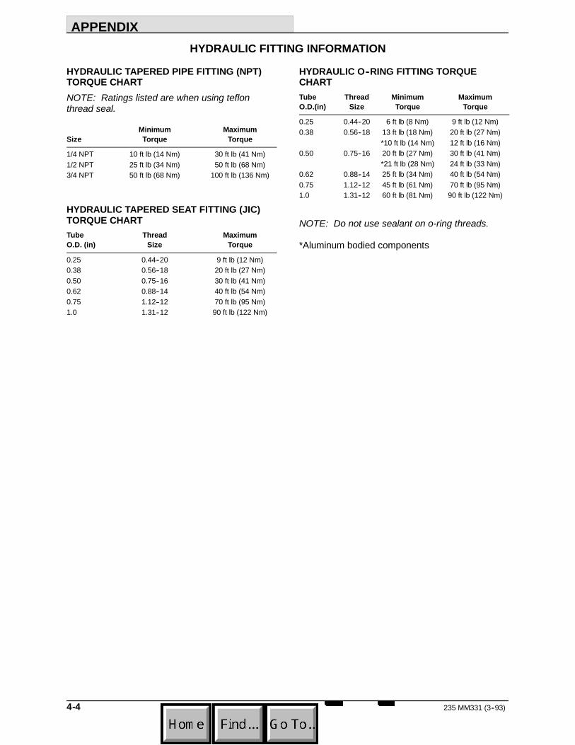
APPENDIX
235 MM331 (3--93)4-4
HYDRAULIC FITTING INFORMATION
HYDRAULIC TAPERED PIPE FITTING (NPT)TORQUE CHARTNOTE: Ratings listed are when using teflonthread seal.
Minimum MaximumSize Torque Torque
1/4 NPT 10 ft lb (14 Nm) 30 ft lb (41 Nm)1/2 NPT 25 ft lb (34 Nm) 50 ft lb (68 Nm)3/4 NPT 50 ft lb (68 Nm) 100 ft lb (136 Nm)
HYDRAULIC TAPERED SEAT FITTING (JIC)TORQUE CHARTTube Thread MaximumO.D. (in) Size Torque
0.25 0.44--20 9 ft lb (12 Nm)0.38 0.56--18 20 ft lb (27 Nm)0.50 0.75--16 30 ft lb (41 Nm)0.62 0.88--14 40 ft lb (54 Nm)0.75 1.12--12 70 ft lb (95 Nm)1.0 1.31--12 90 ft lb (122 Nm)
HYDRAULIC O--RING FITTING TORQUECHARTTube Thread Minimum MaximumO.D.(in) Size Torque Torque
0.25 0.44--20 6 ft lb (8 Nm) 9 ft lb (12 Nm)0.38 0.56--18 13 ft lb (18 Nm) 20 ft lb (27 Nm)
*10 ft lb (14 Nm) 12 ft lb (16 Nm)0.50 0.75--16 20 ft lb (27 Nm) 30 ft lb (41 Nm)
*21 ft lb (28 Nm) 24 ft lb (33 Nm)0.62 0.88--14 25 ft lb (34 Nm) 40 ft lb (54 Nm)0.75 1.12--12 45 ft lb (61 Nm) 70 ft lb (95 Nm)1.0 1.31--12 60 ft lb (81 Nm) 90 ft lb (122 Nm)
NOTE: Do not use sealant on o-ring threads.
*Aluminum bodied components

STANDARD MODEL PARTS
5-1235 MM331 (3--93)
SECTION 5CONTENTS
PageORDERING REPAIR PARTS 5-3. . . . . . . . . . . . . . .Fig. 1 -- Recommended General
Maintenance Items 5-4. . . . . . . . . . . . .Fig. 2 -- Replacement Brushes 5-5. . . . . . . . . . . . . .Fig. 3 -- Main Frame Group 5-6. . . . . . . . . . . . . . . .Fig. 4 -- Seat and Shrouds Group 5-8. . . . . . . . . . .Fig. 5 -- Front Wheel and Brake Group 5-10. . . . . . .Fig. 6 -- Hopper Lift Arms Group 5-12. . . . . . . . . . . .Fig. 7 -- Hopper Middle and Cover Group 5-14. . . . .Fig. 8 -- Hopper Bottom Group 5-16. . . . . . . . . . . . . .Fig. 9 -- Hopper Headlights and
Access Door Group 5-18. . . . . . . . . . . .Fig. 10 -- Hopper Filter and Shaker
Motor Group 5-19. . . . . . . . . . . . . . . . . .Fig. 11 -- Hopper Dump Door and
Actuator Group 5-20. . . . . . . . . . . . . . . . . . .Fig. 12 -- Vacuum Fan Control Group 5-22. . . . . . . .Fig. 13 -- Vacuum Fan Assembly 5-24. . . . . . . . . . . .Fig. 14 -- Main Brush Drive Group 5-26. . . . . . . . . . .Fig. 15 -- Main Brush Idler Group 5-28. . . . . . . . . . . .Fig. 16 -- Side Brush Group 5-30. . . . . . . . . . . . . . . . .Fig. 17 -- Hydraulic Lift Cylinder and
Filter Group 5-32. . . . . . . . . . . . . . . . . . .Fig. 18 -- Pump Group 5-34. . . . . . . . . . . . . . . . . . . . .Fig. 19 -- Control Valve and Throttle Group 5-36. . . .Fig. 20 -- Hydraulic Reservoir Group 5-38. . . . . . . . .Fig. 21 -- Rear Drive Wheel Group 5-39. . . . . . . . . . .Fig. 22 -- Hydraulic Hoses Group 5-40. . . . . . . . . . . .Fig. 23 -- Steering Wheel Group 5-42. . . . . . . . . . . . .Fig. 24 -- Directional Pedal Group 5-44. . . . . . . . . . . .Fig. 25 -- Speed Limiter Group 5-45. . . . . . . . . . . . . .Fig. 26 -- Engine Group 5-46. . . . . . . . . . . . . . . . . . . .Fig. 27 -- Fuel Tank and Line Group 5-48. . . . . . . . . .Fig. 28 -- Control Panel Group 5-50. . . . . . . . . . . . . . .Fig. 29 -- Wire Harness Group 5-52. . . . . . . . . . . . . . .Fig. 30 -- Labels Group 5-54. . . . . . . . . . . . . . . . . . . . .
NOTE: SECTION 5, STANDARD MODEL PARTS,lists repair parts for a standard diesel model machine.This section also contains parts common to allmodels of the machine.

STANDARD MODEL PARTS
235 MM331 (3--93)5-2

STANDARD MODEL PARTS
5-3235 MM331 (3--93)
ORDERING REPAIR PARTSThe components used in this machine have beencarefully selected for performance and safety. Useonly TENNANT specified or equivalent parts.
To receive prompt service in filling of your partsorders, please direct all orders for parts withTENNANT part numbers to the TENNANT, and allorders for parts with vendor part numbers to the localsupplier of the respective vendor.
When ordering parts, please furnish all of thefollowing information:
1. Machine model number - shown on the machinedata plate.
SER.NO.GVW. LBS. KG.
TENNANT COMPANYMINNEAPOLIS, MINN USA
2. Machine serial number - shown on the machinedata plate.
3. Power source - gasoline, LPG, diesel, electric.
4. Company name.
5. Shipping address.
6. Billing address.
7. Name, first and last - of person ordering parts.
8. Telephone number.
9. Purchase order number.
10. Part number, description, and quantity - of eachitem on the order.
11. Customer ID Number.
Do not order parts by key number or the figurenumber of the illustrated parts. Indented itemsindicate parts of assemblies. Standard hardware isfurnished only when part of a purchased assembly.Please get hardware from a local hardware supplier.
If the old part cannot be identified, send it to us withthe quantity needed specified on the order.
Any claim for loss or damage to a shipment in transitshould be filed promptly against the transportationcompany making the delivery. Shipments will becomplete unless the packing list or order ack-nowledgement indicate items back ordered.
If parts received are suspected to be incorrect ordefective, please write, wire, or phone the TENNANTrepresentative from whom you ordered the part. Theywill give authorization for return and/or handlereplacement shipments when required.
SERIAL NUMBER INFORMATION EXPLANATIONSerial number listings are shown to indicate on whichmachines each part can be used. These listings areexplained by the following examples:
(000000-- ) The part can be used on all machines.
(003342-- ) The part can be used on all machinesbeginning with the serial number listed.
(000000--004320) The part can be used on allmachines up to and including serial number listed.
(004321--005678) The part can be used on allmachines between and including the serial numberslisted.
Where xxxxxx’s are listed in place of a serial number,it indicates a change was made but the exact serialnumber had not been established when the catalogwent to press.
SI UNITS OF MEASURE(INTERNATIONAL SYSTEM)Metric equivalents have been included, whereapplicable, throughout this parts catalog.
FASTENER STRENGTH IDENTIFICATIONFasteners required to have high--strength qualitiesequivalent to SAE Grade 8 are identified throughoutthis catalog by the description GR 8. Unless identifiedby this description, all standard fasteners are SAEGrade 5.
(Specifications and design subject to change withoutnotice.)

STANDARD MODEL PARTS
235 MM331 (3-94)5-4
06969Fig. 1 -- Recommended General Maintenance Items
TENNANT MachineKey Part No. Serial Number Description Qty.
87960 (000000-- ) Maintenance Kit, 400 Hour, Diesel 187171 (000000-- ) Element, Pre--Cleaner 187875 (000000-- ) Element, Air Cleaner 187928 (000000-- ) Gasket Kit, Breather 187929 (000000-- ) Gasket, Breather 187930 (000000-- ) Element, Breather 187737 (000000-- ) Hose, Rubber, 5.5 in (140 mm) 182509 (000000-- ) Hose, Fuel Line, 11 in (280 mm) 187730 (000000-- ) Hose, Rubber, 12 in (305 mm) 187738 (000000-- ) Hose, Rubber, 29 in (735 mm) 187870 (000000-- ) Filter, Engine Oil 665870--5 (000000-- ) Hydraulic Fluid, (5/20), 5 gal (18.9 L) 167718--2 (000000-- ) Element, Hydraulic Filter 182692 (000000-- ) Element, Diesel Fuel Filter 187963 (000000-- ) Maintenance Kit, Hopper 187405 (000000-- ) Seal, Hopper Halves 187217 (000000-- ) Seal, Hopper Cover 187338 (000000-- ) Seal, Access Door 168198 (000000-- ) Adhesive, 1 oz (30 ml) 187061 (000000-- ) Lip, Hopper Rear 187060 (000000-- ) Retainer, Hopper Lip 187412 (000000-- ) Seal, Dump Door 287413 (000000-- ) Spacer, Seal 287689 (000000-- ) Cord, Sponge 187688 (000000-- ) Wrap, Dump Door Seal 187687 (000000-- ) Retainer, Hopper Seal 187164 (000000-- ) Seal, Dump Door Top 187165 (000000-- ) Retainer, Seal 187167 (000000-- ) Retainer, Door Seal 134323 (000000-- ) Screw, Hex, Nylon Lock 587964 (000000-- ) Maintenance Kit, Rear Skirt 187197 (000000-- ) Flap, Recirculation 187199 (000000-- ) Seal, Rear Brush Wrap 187586 (000000-- ) Angle, Recirculation Flap 187206 (000000-- ) Retainer, Rear Seal 134292 (000000-- ) Screw, Hex, Nylon Lock 787965 (000000-- ) Maintenance Kit, Seals 187465 (000000-- ) Seal, Brush Lift Handle 187464 (000000-- ) Retainer, Brush Lift Seal 187181 (000000-- ) Seal, Hopper Top 187180 (000000-- ) Retainer, Hopper Top Seal 187211 (000000-- ) Skirt, Lower, L.H. 187555 (000000-- ) Retainer, Lower Skirt 187975 (000000-- ) Retainer, Skirt, L.H. 187184 (000000-- ) Seal, Hopper, L.H. 187182 (000000-- ) Retainer, Felt Seal 134292 (000000-- ) Screw, Hex, Nylon Lock 487175 (000000-- ) Skirt, Lower, R.H. 187176 (000000-- ) Retainer, Lower Seal 187183 (000000-- ) Seal, Hopper, R.H. 187182 (000000-- ) Retainer, Felt Seal 187353 (000000-- ) Seal, Foam Rubber 287354 (000000-- ) Seal, Foam Rubber 2

STANDARD MODEL PARTS
5-5235 MM331 (3--93)
Fig. 1 -- Recommended General Maintenance Items
TENNANT MachineKey Part No. Serial Number Description Qty.
87731 (000000-- ) Seal, Foam Rubber 168198 (000000-- ) Adhesive, 1 oz (30 ml) 147069 (000000-- ) Sleeve, Vacuum Fan Tube 1
1
2
03561Fig. 2 -- Replacement Brushes
TENNANT MachineKey Part No. Serial Number Description Qty.
1 87419 (000000-- ) Side Brush, Polypropylene 11 87420 (000000-- ) Side Brush, Nylon 12 87333 (000000-- ) Main Brush, 24 Single Row, Polyester 12 87097 (000000-- ) Main Brush, 8 Double Row, Proex and Wire 12 87334 (000000-- ) Main Brush, 8 Double Row, Polyester 12 87099 (000000-- ) Main Brush, 8 Double Row, Polypropylene 1

STANDARD MODEL PARTS
235 MM331 (3-94)5-6
2
3
45
6
7
89
10
1
11
12 13
1415
16 17
18
19
20
21
22 2324
25
26
27
28
18
4
5
4
Fig. 3 -- Main Frame Group

STANDARD MODEL PARTS
5-7235 MM331 (3--93)
03462Fig. 3 -- Main Frame Group
TENNANT MachineKey Part No. Serial Number Description Qty.
1 87500 (000000-- ) Frame, Main 12 87181 (000000-- ) Seal, Hopper Top 13 87180 (000000-- ) Retainer, Seal 14 34292 (000000-- ) Screw, Nylon Hex 115 87182 (000000-- ) Retainer, Felt Seal 26 87184 (000000-- ) Seal, Hopper, L.H. 17 87183 (000000-- ) Seal, Hopper, R.H. 18 87190 (000000-- ) Door Assembly, Brush, R.H. 19 87353 (000000-- ) Seal, Foam Rubber 1
10 87354 (000000-- ) Seal, Foam Rubber 111 87731 (000000-- ) Seal, Foam Rubber 112 87176 (000000-- ) Retainer, Lower Seal 113 87175 (000000-- ) Skirt, Lower, R.H. 114 87464 (000000-- ) Retainer, Seal 115 87465 (000000-- ) Seal, Brush Lift Handle 116 87211 (000000-- ) Skirt, Lower, L.H. 117 87555 (000000-- ) Retainer, Lower Skirt 118 01760 (000000-- ) Nut, Nylon Lock 419 87189 (000000-- ) Door Assembly, Brush, L.H. 120 87353 (000000-- ) Seal, Foam Rubber 121 87354 (000000-- ) Seal, Foam Rubber 122 87197 (000000-- ) Flap, Recirculation 123 87586 (000000-- ) Angle, Recirculation Flap 124 87199 (000000-- ) Seal, Rear 125 87206 (000000-- ) Retainer, Rear Seal 126 47277 (000000-- ) Chain, Link 127 87975 (000000-- ) Retainer, Skirt, L.H. 128 87970 (000000-- ) Seal, Foam 1

STANDARD MODEL PARTS
235 MM331 (3-94)5-8
MainFrame
11
7
1
3
8
9
6
42
14
1312
10
5
15
16
17
Fig. 4 -- Seat and Shrouds Group

STANDARD MODEL PARTS
5-9235 MM331 (3-94)
03565Fig. 4 -- Seat and Shrouds Group
TENNANT MachineKey Part No. Serial Number Description Qty.
1 82342 (000000-- ) Seat Assembly 12 68275 (000000--002611 ) Pouch, Operator’s Manual, 13.6 in (345 mm) 12 48790 (002612-- ) Pouch, Operator’s Manual, 7.5 in (190 mm) 13 87612 (000000-- ) Latch, Shroud 14 62170--2 (000000-- ) Molding, Rigid 15 43454 (000000-- ) Washer, Nylon 26 87581 (000000-- ) Spring, Torsion 17 87481 (000000-- ) Shroud 18 87407 (000000-- ) Insulation, Foam 19 87408 (000000-- ) Insulation, Foam 1
10 29233 (000000-- ) Bumper, Rubber 311 36192 (000000-- ) Lanyard Assembly 112 87705 (000000-- ) Tie Down, Cable 513 49266 (000000-- ) Tie, Cable 614 46236 (000000-- ) Clamp, Cable 215 87346 (000000-- ) Taillight Assembly 2
87948 (000000-- ) Bulb 187949 (000000-- ) Socket Assembly 1
16 87305 (000000-- ) Bracket, Seat Support 117 57772 (000000-- ) Plate, Cover 2

STANDARD MODEL PARTS
235 MM331 (3--93)5-10
MainFrame
20
15
12
75
19
1716
18
1413
1236
2122
22
10 9
8
4
11
24
Fig. 5 -- Front Wheel and Brake Group

STANDARD MODEL PARTS
5-11235 MM331 (3--93)
03477Fig. 5 -- Front Wheel and Brake Group
TENNANT MachineKey Part No. Serial Number Description Qty.
1 86922 (000000-- ) Cap, Hub 22 87053 (000000-- ) Nut, Slotted 23 28862 (000000-- ) Washer, Thrust 24 87253 (000000-- ) Wheel Assembly 25 87195 (000000-- ) Tire, Solid 16 46390 (000000-- ) Bearing, Ball 27 39296 (000000-- ) Screw, Socket 128 87050 (000000-- ) Shaft, Front Wheel 29 87046 (000000-- ) Hub, Front Wheel 2
10 26315 (000000-- ) Pin, Roll 211 87270 (000000-- ) Rod, Brake 212 13352 (000000-- ) Spring, Tension 213 14595--1 (000000-- ) Clevis, Adjustable 214 14605 (000000-- ) Pin, Clevis 215 87134 (000000-- ) Shaft, Brake 116 51109 (000000-- ) Pad 117 51562 (000000-- ) Sleeve 218 51545 (000000-- ) Lever, Brake 119 87248 (000000-- ) Arm, Extension 220 10120 (000000-- ) Pin, Clevis 121 87142 (000000-- ) Brake Assembly 222 87868 (000000-- ) Shoes, Brake (Set for 1 Wheel) 123 87869 (000000-- ) Springs, Brake (Set for 1 Wheel) 124 87966 (000000-- ) Clip 1

STANDARD MODEL PARTS
235 MM331 (3--93)5-12
7
46
5
15
3
2
9
10
12
12
14
MainFrame
11
11
8
1
13
13
Fig. 6 -- Hopper Lift Arms Group
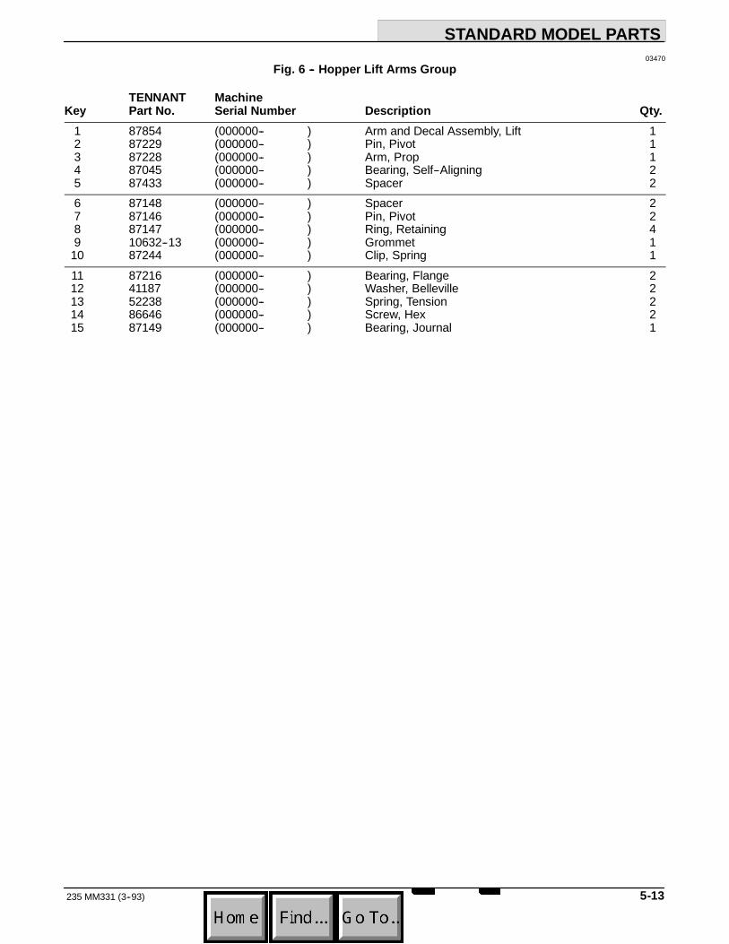
STANDARD MODEL PARTS
5-13235 MM331 (3--93)
03470Fig. 6 -- Hopper Lift Arms Group
TENNANT MachineKey Part No. Serial Number Description Qty.
1 87854 (000000-- ) Arm and Decal Assembly, Lift 12 87229 (000000-- ) Pin, Pivot 13 87228 (000000-- ) Arm, Prop 14 87045 (000000-- ) Bearing, Self--Aligning 25 87433 (000000-- ) Spacer 26 87148 (000000-- ) Spacer 27 87146 (000000-- ) Pin, Pivot 28 87147 (000000-- ) Ring, Retaining 49 10632--13 (000000-- ) Grommet 1
10 87244 (000000-- ) Clip, Spring 111 87216 (000000-- ) Bearing, Flange 212 41187 (000000-- ) Washer, Belleville 213 52238 (000000-- ) Spring, Tension 214 86646 (000000-- ) Screw, Hex 215 87149 (000000-- ) Bearing, Journal 1

STANDARD MODEL PARTS
235 MM331 (3--93)5-14
HopperBottom
FrontPlate
12
13
2
2
1
3
5
4
5
6
98
7
10
11
HopperBack
1415
Fig. 7 -- Hopper Middle and Cover Group

STANDARD MODEL PARTS
5-15235 MM331 (3--93)
03268Fig. 7 -- Hopper Middle and Cover Group
TENNANT MachineKey Part No. Serial Number Description Qty.
1 87203 (000000-- ) Cover, Hopper 12 87579 (000000-- ) Latch, Tension 23 87217 (000000-- ) Seal, Hopper Cover 14 87202 (000000-- ) Hopper, Middle 15 87056 (000000-- ) Strike, Hopper Cover 26 87405 (000000-- ) Seal 17 87165 (000000-- ) Retainer, Seal 18 87167 (000000-- ) Retainer, Door Seal 19 87164 (000000-- ) Seal, Dump Door 1
10 87390 (000000-- ) Baffle, Debris, L.H. 111 87166 (000000-- ) Baffle, Debris, R.H. 112 87113 (000000-- ) Plate, Pivot, L.H. 113 87114 (000000-- ) Plate, Pivot, R.H. 114 34323 (000000-- ) Screw, Nylon Hex 515 87958 (000000-- ) Washer, Nylon 6

STANDARD MODEL PARTS
235 MM331 (3--93)5-16
6
2
3
2
1
HopperMiddle
9
8
7
4
5
4
11
10
10
12
Fig. 8 -- Hopper Bottom Group

STANDARD MODEL PARTS
5-17235 MM331 (12--94)
03267Fig. 8 -- Hopper Bottom Group
TENNANT MachineKey Part No. Serial Number Description Qty.
1 87059 (000000-- ) Plate, Hopper Bottom 12 87103 (000000-- ) Angle, Support 23 87201 (000000-- ) Hopper, Bottom 14 87406 (000000-- ) Angle, Bottom Support 25 87208 (000000-- ) Plate, Front 16 87461 (000000-- ) Angle, Stiffener 17 87061 (000000-- ) Lip, Rear 18 87060 (000000-- ) Retainer, Lip 19 87117 (000000-- ) Bumper, Front 1
10 87958 (000000-- ) Washer, Nylon 411 87969 (000000-- ) Deflector, Hopper, R.H. 112 87979 (000000-- ) Deflector, Hopper, L.H. 1

STANDARD MODEL PARTS
235 MM331 (3--93)5-18
6
8
HopperMiddle
2
1
5
3
9
74
4
03467Fig. 9 -- Hopper Headlights and Access Door Group
TENNANT MachineKey Part No. Serial Number Description Qty.
1 87460 (000000-- ) Mount, Headlight 22 87430 (000000-- ) Lamp 23 87739 (000000-- ) Guard, Headlight 24 87337 (000000-- ) Latch, Door 25 87621 (000000-- ) Door, Access 16 87338 (000000-- ) Seal, Access Door 17 26395--2 (000000-- ) Clamp, Cable 28 10632--11 (000000-- ) Grommet, Rubber 19 10632--15 (000000-- ) Grommet, Rubber 1

STANDARD MODEL PARTS
5-19235 MM331 (3--93)
1
2
10
4
4
11
11
5
8
5
9
67
HopperMiddle
3
1313
12
14
1412
03468Fig. 10 -- Hopper Filter and Shaker Motor Group
TENNANT MachineKey Part No. Serial Number Description Qty.
1 54121 (000000-- ) Motor, Shaker 12 87074 (000000-- ) Bracket, Shaker Filter 13 40678 (000000-- ) Clamp, Cable 24 87209 (000000--001391 ) Bracket, Shaker Mount 24 87985 (001392-- ) Bracket, Shaker Mount 25 51322 (000000-- ) Isolator, Vibration 46 87306 (000000-- ) Weight, Eccentric 17 87286 (000000-- ) Screw, Hex 28 20634 (000000-- ) Screw, Nylon Set 29 87546 (000000-- ) Thermostat 1
10 87550 (000000--001391 ) Filter Assembly 110 87341 (001392-- ) Filter Assembly 111 87084 (000000-- ) Plate, Mount 212 87967 (000000-- ) Strip, Seal Retainer 213 87968 (000000-- ) Strip, Seal Retainer 214 87982 (000000-- ) Bar, Shaker 2
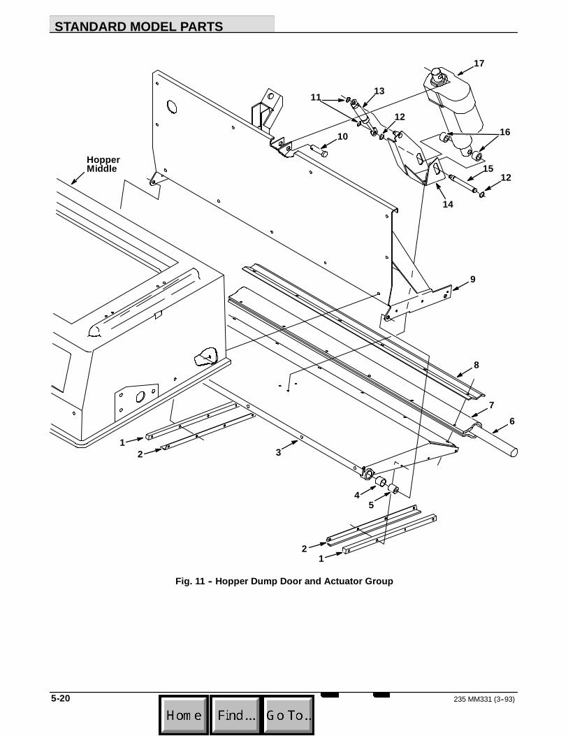
STANDARD MODEL PARTS
235 MM331 (3--93)5-20
HopperMiddle
3
10
13
12
17
1512
8
76
14
45
12
21
9
16
11
Fig. 11 -- Hopper Dump Door and Actuator Group

STANDARD MODEL PARTS
5-21235 MM331 (3-94)
03466Fig. 11 -- Hopper Dump Door and Actuator Group
TENNANT MachineKey Part No. Serial Number Description Qty.
1 87413 (000000-- ) Spacer, Seal 22 87412 (000000-- ) Seal, Dump Door 23 87162 (000000-- ) Door, Dump 14 64379 (000000-- ) Bearing, Journal 25 87104 (000000-- ) Bushing, Door Pivot 26 87689 (000000-- ) Cord, Sponge 17 87688 (000000-- ) Seal Wrap, Dump Door 18 87687 (000000-- ) Retainer, Hopper Seal 19 87108 (000000-- ) Back, Hopper 1
10 63147 (000000-- ) Pin, Clevis 111 23524--1 (000000-- ) Ring, Retaining 212 23524 (000000-- ) Ring, Retaining 213 65577 (000000-- ) Spring, Gas 114 87120 (000000-- ) Mount, Dump Door Actuator 115 87152 (000000-- ) Pin, Actuator 116 87693 (000000-- ) Spacer, Actuator Mount 217 87444 (000000-- ) Actuator 1

STANDARD MODEL PARTS
235 MM331 (3--93)5-22
FanHousing
5
7 6 4 3 2
1
1
10
8
MainFrame
1211
13
914
Fig. 12 -- Vacuum Fan Control Group

STANDARD MODEL PARTS
5-23235 MM331 (3--93)
03464Fig. 12 -- Vacuum Fan Control Group
TENNANT MachineKey Part No. Serial Number Description Qty.
1 23498 (000000-- ) Clamp, Worm Drive 22 87051 (000000-- ) Duct, Vacuum 13 49300 (000000-- ) Damper14 87983 (000000-- ) Seal, Damper 15 87265 (000000-- ) Tube, Vacuum Fan 16 46140 (000000-- ) Plate, Damper 17 47069 (000000-- ) Sleeve 18 87580 (000000-- ) Rod, Damper 19 09087 (000000-- ) Spring, Tension 2
10 87573 (000000-- ) Lever, Vacuum Fan 111 87707 (000000-- ) Boot, Solenoid 112 87585 (000000-- ) Solenoid Assembly 113 44078 (000000-- ) Switch 114 87280 (000000-- ) Bracket, Shaker Switch 1

STANDARD MODEL PARTS
235 MM331 (3--93)5-24
MainFrame
1011
98
7654
1312
2
1
14
153
VacuumDuct
Fig. 13 -- Vacuum Fan Assembly

STANDARD MODEL PARTS
5-25235 MM331 (3--93)
03465Fig. 13 -- Vacuum Fan Assembly
TENNANT MachineKey Part No. Serial Number Description Qty.
1 87251 (000000-- ) Housing, Fan 12 08143 (000000-- ) Impeller13 87853 (000000-- ) Plate and Decal Assembly 14 10362 (000000-- ) Spacer 15 00960 (000000-- ) Key, Square 16 16934 (000000-- ) Shaft, Bearing and Flange Assembly 17 00500--4 (000000-- ) Key, Woodruff 18 87620 (000000-- ) Arm, Vacuum Fan 19 87630 (000000-- ) Sheave, Fan 1
10 39328 (000000-- ) Screw, Set 211 25494 (000000-- ) Turnbuckle 112 06279 (000000-- ) Pin, Clevis 113 87860 (000000-- ) Bracket, Vacuum Fan 114 87832 (000000-- ) Deflector, Vacuum Fan 115 87299 (000000-- ) Nut , Flex Lock 1

STANDARD MODEL PARTS
235 MM331 (3--93)5-26
MainFrame
12
3
5
27
28
46
7
910
11
151412
13
16
MainBrushTube
8
2324
2221
18
17
20
26
25
67
19
29
Fig. 14 -- Main Brush Drive Group

STANDARD MODEL PARTS
5-27235 MM331 (3-94)
03262Fig. 14 -- Main Brush Drive Group
TENNANT MachineKey Part No. Serial Number Description Qty.
1 39527 (000000-- ) Nut, Slotted 12 39350 (000000-- ) Washer 13 87631 (000000-- ) Plug, Brush Drive 14 87040 (000000-- ) Shaft, Drive 15 00928 (000000-- ) Key, Square 16 09005 (000000-- ) Ring, Retaining 27 13534 (000000-- ) Bearing, Ball 28 87368 (000000-- ) Flange, Debris 19 87030 (000000-- ) Arm, Main Brush 1
10 87078 (000000-- ) Washer, Brush Arm 111 87027 (000000--001437 ) Sheave, Mounting Shaft (Replaced by 87267) 112 49495 (000000-- ) Sheave 113 23225 (000000--001437 ) Ring, Retaining 114 01844 (000000-- ) Bearing, Ball 115 23224 (000000-- ) Ring, Retaining 116 49439 (000000-- ) Sheave 117 01866 (000000-- ) Pin, Roll 118 82842 (000000-- ) Screw, Nylon Hex 119 02356 (000000-- ) Pulley, Idler 120 87474 (000000-- ) V--Belt 121 33123 (000000-- ) Screw, Shoulder 122 09370 (000000-- ) Pin, Clevis 123 46785--1 (000000-- ) Spring, Tension 124 87645 (000000-- ) Arm Assembly, Idler 125 87646 (000000-- ) Bearing, Bronze 126 30205 (000000-- ) Screw, Leveler 127 87215 (000000-- ) Housing, Bearing 128 87080 (000000-- ) Bearing 129 87267 (001438-- ) Spacer, Bearing 1

STANDARD MODEL PARTS
235 MM331 (3--93)5-28
MainFrame
2
1
4 5
3
6
17
16
5 415
14
1312
11
10
98
7
Fig. 15 -- Main Brush Idler Group

STANDARD MODEL PARTS
5-29235 MM331 (3--93)
03263Fig. 15 -- Main Brush Idler Group
TENNANT MachineKey Part No. Serial Number Description Qty.
1 16447 (000000-- ) Grip, Handle 12 87275 (000000-- ) Handle, Brush Lift 13 55347 (000000-- ) Screw, Hex 14 09005 (000000-- ) Ring, Retaining 25 13534 (000000-- ) Bearing, Ball 26 87078 (000000-- ) Washer, Brush Arm 17 87080 (000000-- ) Bearing 18 87088 (000000-- ) Bracket, Bearing Housing 19 87215 (000000-- ) Housing, Bearing 1
10 87082 (000000-- ) Tube, Main Brush 111 39527 (000000-- ) Nut, Slotted 112 39350 (000000-- ) Washer 113 87631 (000000-- ) Plug, Brush Drive 114 00928 (000000-- ) Key, Square 115 87041 (000000-- ) Shaft, Idler 116 87368 (000000-- ) Flange, Debris 117 87030 (000000-- ) Arm, Main Brush 1

STANDARD MODEL PARTS
235 MM331 (3--93)5-30
26
25
27
23
222120Side
Brush
16
19
17
10
FrontBumper
13
15
14
1211
9
87
6
5
3
2
1
24
MainFrame andLift Arms 4
18
6
7
28
Fig. 16 -- Side Brush Group

STANDARD MODEL PARTS
5-31235 MM331 (3--93)
03274Fig. 16 -- Side Brush Group
TENNANT MachineKey Part No. Serial Number Description Qty.
1 16447 (000000-- ) Grip, Handle 12 87574 (000000-- ) Handle, Side Brush 13 87297 (000000-- ) Cable, Brush Adjustment 14 04734 (000000-- ) Pin, Clevis 15 45261 (000000-- ) Spring, Compression 16 87627 (000000-- ) Strip, Spring 27 49266 (000000-- ) Tie, Cable 38 57452 (000000-- ) Sleeve, Hydraulic 19 87298 (000000-- ) Cable, Brush Lift 1
10 36468 (000000-- ) Knob 111 36070 (000000-- ) Pulley, Cable 112 04733 (000000-- ) Pin, Clevis 113 87293 (000000-- ) Block, Threaded 114 58670 (000000-- ) Screw, Nylon Hex 115 87297 (000000-- ) Cable, Brush Adjustment 116 87172 (000000-- ) Cable, Side Brush 117 87170 (000000-- ) Channel, Side Brush Mounting 118 87242 (000000-- ) Spring 119 87221 (000000-- ) Bracket, Motor Mounting 120 41185 (000000-- ) Washer, Belleville 121 41178 (000000-- ) Washer 122 87418 (000000-- ) Mount 123 87439 (000000-- ) Deflector, Side Brush 124 87656 (000000-- ) Sleeve, Hydraulic 125 87475 (000000--001891 ) Motor, Hydraulic (See Hydraulic Components) 125 28804 (001892-- ) Motor, Hydraulic (See Hydraulic Components) 126 57984 (000000-- ) Fitting, Straight 227 39210 (000000-- ) Fitting, Elbow 128 87950 (000000-- ) Deflector 1

STANDARD MODEL PARTS
235 MM331 (3-94)5-32
365
1
56
4
2
1213
7
8
11
910
1415
Fig. 17 -- Hydraulic Lift Cylinder and Filter Group

STANDARD MODEL PARTS
5-33235 MM331 (3-94)
03471Fig. 17 -- Hydraulic Lift Cylinder and Filter Group
TENNANT MachineKey Part No. Serial Number Description Qty.
1 51787 (000000-- ) Bumper, Rubber 12 48657 (000000-- ) Bracket, Filter 13 67718 (000000-- ) Filter Assembly 14 67718--2 (000000-- ) Element, Hydraulic Filter 15 47519 (000000-- ) Fitting, Straight 26 55686 (000000-- ) Fitting, Straight 27 82802 (000000-- ) Fitting, Cross 18 87414 (000000-- ) Fitting, Straight 19 47638 (000000-- ) Fitting, Elbow 1
10 16455 (000000-- ) Fitting, Restrictor 111 87055 (000000--002748 ) Cylinder, Hydraulic (See Hydraulic Components) 111 48575 (002749--003295 ) Cylinder, Hydraulic (See Hydraulic Components) 111 65223 (003296-- ) Cylinder, Hydraulic (See Hydraulic Components) 112 87079 (000000-- ) Clevis, Cylinder 113 04733--4 (000000-- ) Pin, Clevis 114 32969 (000000-- ) Washer 115 46482 (003296-- ) Fitting, Plug 1

STANDARD MODEL PARTS
235 MM331 (3--93)5-34
22
23
21
21
1
28
2726
25
19
20
2
12
16
14
13
9
5
8
1110
17
29
3231
30
15
MainFrame
24
18
3
46
7
V-Belt33
Fig. 18 -- Pump Group

STANDARD MODEL PARTS
5-35235 MM331 (3--93)
03479Fig. 18 -- Pump Group
TENNANT MachineKey Part No. Serial Number Description Qty.
1 87732 (000000-- ) Guard, Belt 12 87513 (000000-- ) Sheave, Propelling Pump 13 15280--3 (000000-- ) Bushing, Key 14 39330 (000000-- ) Screw, Set 25 87236 (000000-- ) Plate Assembly, Retaining 16 26103 (000000-- ) Pin, Roll 27 39332 (000000-- ) Screw, Set 28 87511 (000000-- ) Sheave, Pump 19 87474 (000000-- ) V--Belt 1
10 87451 (000000-- ) Pump, Accessory 111 47638 (000000-- ) Fitting, Elbow 112 56835 (000000-- ) Fitting, Straight 113 87521 (000000-- ) Bracket, Pump Mounting 114 87512 (000000-- ) Sheave, Pump 115 39330 (000000-- ) Screw, Set 216 87543 (000000-- ) V--Belt 117 87370 (000000-- ) Mount, Pump (See Hydraulic Components) 118 87365 (000000-- ) Tube, Spacer 219 87362 (000000-- ) Block, Stop 120 02218 (000000-- ) Screw, Full Thread Hex 121 87351 (000000-- ) Arm, Pintle Centering 222 87222 (000000-- ) Spring, Extension 223 87360 (000000-- ) Arm, Pintle 124 26103 (000000-- ) Pin, Roll 125 57984 (000000-- ) Fitting, Straight 126 56692 (000000-- ) Fitting, Straight 127 47508 (000000-- ) Fitting, Straight 128 42215 (000000-- ) Fitting, Tee 129 47513 (000000-- ) Fitting, Elbow, 45_ 1
87735 (000000-- ) Pump Assembly, Hydraulic 130 87734 (000000-- ) Pump, Hydraulic (See Hyd. Components) 131 69159 (000000-- ) Gasket, Pump 132 69158 (000000-- ) Plate, Backing 133 86646 (000000-- ) Screw, Full Thread 2

STANDARD MODEL PARTS
235 MM331 (3--93)5-36
3
2
10
11
13
14
14
9
6
7
5 4
8
12
4
4
ControlPanel
1
Fig. 19 -- Control Valve and Throttle Group

STANDARD MODEL PARTS
5-37235 MM331 (3--93)
06966Fig. 19 -- Control Valve and Throttle Group
TENNANT MachineKey Part No. Serial Number Description Qty.
1 87246 (000000-- ) Grip, Vinyl 22 87810 (000000-- ) Lever, Throttle 13 43242 (000000-- ) Swivel 14 43454 (000000-- ) Washer, Nylon 75 87818 (000000-- ) Seal, Cable 16 87811 (000000-- ) Bracket, Cable Guide 17 87779 (000000-- ) Cable Assembly, Throttle 18 87816 (000000-- ) Spring, Tension 19 55686 (000000-- ) Fitting, Straight 2
10 87375 (000000-- ) Lever, Hydraulic Valve 111 87376 (000000-- ) Arm, Extension 112 14605 (000000-- ) Pin, Clevis 113 87409 (000000-- ) Valve, Hydraulic (See Hyd. Components) 114 57984 (000000-- ) Fitting, Straight 2

STANDARD MODEL PARTS
235 MM331 (8--95)5-38
3
MainFrame
5
7
6 8
4
1
2
9
10
11
03481Fig. 20 -- Hydraulic Reservoir Group
TENNANT MachineKey Part No. Serial Number Description Qty.
1 87392 (000000-- ) Reservoir Assembly 12 31559 (000000-- ) Breather, Filler 13 61288 (000000-- ) Gasket, Hyd Tank Breather 24 25121 (000000-- ) Breather, Hyd Cap 15 70006 (000000-- ) Gasket, Cap 16 40362 (000000-- ) Fitting, Plug 17 87484 (000000-- ) Strap, Tank 28 82784 (000000-- ) Strainer, Hydraulic 19 47508 (000000-- ) Fitting, Straight 1
10 02545 (000000-- ) Fitting, Straight 111 13773 (000000-- ) Sleeve, Nylon 1
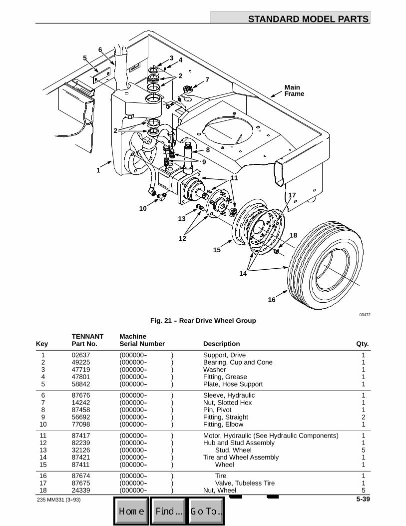
STANDARD MODEL PARTS
5-39235 MM331 (3--93)
15
16
1310
1
56
12
7
3
2
4
MainFrame
17
18
14
2
98
11
03472Fig. 21 -- Rear Drive Wheel Group
TENNANT MachineKey Part No. Serial Number Description Qty.
1 02637 (000000-- ) Support, Drive 12 49225 (000000-- ) Bearing, Cup and Cone 13 47719 (000000-- ) Washer 14 47801 (000000-- ) Fitting, Grease 15 58842 (000000-- ) Plate, Hose Support 16 87676 (000000-- ) Sleeve, Hydraulic 17 14242 (000000-- ) Nut, Slotted Hex 18 87458 (000000-- ) Pin, Pivot 19 56692 (000000-- ) Fitting, Straight 2
10 77098 (000000-- ) Fitting, Elbow 111 87417 (000000-- ) Motor, Hydraulic (See Hydraulic Components) 112 82239 (000000-- ) Hub and Stud Assembly 113 32126 (000000-- ) Stud, Wheel 514 87421 (000000-- ) Tire and Wheel Assembly 115 87411 (000000-- ) Wheel 116 87674 (000000-- ) Tire 117 87675 (000000-- ) Valve, Tubeless Tire 118 24339 (000000-- ) Nut, Wheel 5

STANDARD MODEL PARTS
235 MM331 (3--93)5-40
AccessoryPump
PropellingPump
ControlValve
PropellingMotor
HydraulicReservoir
HydraulicFilter
HopperLiftCylinder
SideBrushMotor
5
9
8
4
2
3
6
7
4
10
1
Fig. 22 -- Hydraulic Hoses Group

STANDARD MODEL PARTS
5-41235 MM331 (3--93)
03461Fig. 22 -- Hydraulic Hoses Group
TENNANT MachineKey Part No. Serial Number Description Qty.
1 82816 (000000-- ) Hose, Hydraulic 12 87652 (000000-- ) Hose, Hydraulic 13 87651 (000000-- ) Hose, Hydraulic 14 34358 (000000-- ) Hose, Hydraulic 25 57965 (000000-- ) Hose, Hydraulic 16 87672 (000000-- ) Hose, Hydraulic 17 82809 (000000-- ) Hose, Hydraulic 18 87680 (000000-- ) Hose, Hydraulic 19 87678 (000000-- ) Hose, Hydraulic 1
10 57219 (000000-- ) Hose, Hydraulic 2

STANDARD MODEL PARTS
235 MM331 (3--93)5-42
1
3
4
6
MainFrame
13
2
8
9
712
11
10
11
5
14
Fig. 23 -- Steering Wheel Group

STANDARD MODEL PARTS
5-43235 MM331 (3--93)
03475Fig. 23 -- Steering Wheel Group
TENNANT MachineKey Part No. Serial Number Description Qty.
1 57497 (000000-- ) Cap, Rubber 12 49452 (000000-- ) Gear Assembly, Steering 13 87488 (000000-- ) Wheel, Steering 14 87753 (000000-- ) Bracket, Steering Column 15 87752 (000000-- ) Seal, Rubber 16 87257 (000000-- ) Spacer, Horn 17 51449 (000000-- ) Bearing, Flange 28 48050 (000000-- ) Bearing and Collar 19 44078 (000000-- ) Switch 1
10 87109 (000000-- ) Link, Drag 111 07259 (000000-- ) Fitting, Grease 212 87820 (000000-- ) Arm, Pitman 113 14138A (000000-- ) Horn, 12 V 114 87762 (000000-- ) Floormat 1

STANDARD MODEL PARTS
235 MM331 (3--93)5-44
1
MainFrame
4
6
7
9
3
5
5
8
5
2
03473Fig. 24 -- Directional Pedal Group
TENNANT MachineKey Part No. Serial Number Description Qty.
1 87254 (000000-- ) Cover, Bellcrank 12 42240 (000000-- ) Pedal, Foot 13 87881 (000000-- ) Arm, Pedal 14 06474A (000000-- ) Pin, Clevis 15 14506 (000000-- ) Ball Joint 46 87155 (000000-- ) Rod, Control 17 87198 (000000-- ) Bellcrank 18 87131 (000000-- ) Rod, Control 19 82839 (000000-- ) Pad, Tread 1

STANDARD MODEL PARTS
5-45235 MM331 (3--93)
4
63
HopperLiftArm
3
2
57
1
03476Fig. 25 -- Speed Limiter Group
TENNANT MachineKey Part No. Serial Number Description Qty.
1 87803 (000000-- ) Bracket, Pivot Pin 12 87491 (000000-- ) Link, Upper 13 45127 (000000-- ) Ring, Retaining 24 87804 (000000-- ) Link, Lower 15 87798 (000000-- ) Bracket, Cam Mounting 16 87797 (000000-- ) Cam, Speed Limiter 17 29584 (000000-- ) Pin, Clevis 1
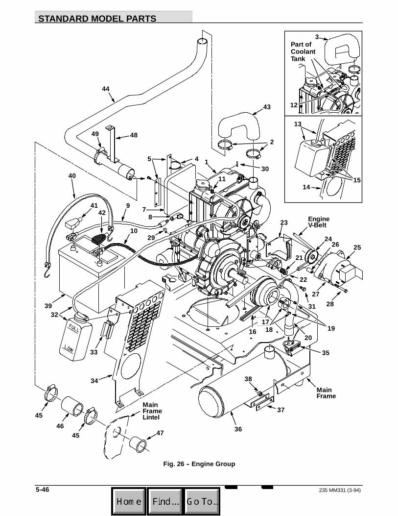
STANDARD MODEL PARTS
235 MM331 (3-94)5-46
23
2
3
2425
87
6
4 1
29
12
21
13
1415
5
201816
17
26
2728
22
19
11
EngineV-Belt
MainFrame
36
30
31
Part ofCoolantTank
32
33
34
40
35
38
4142
39
9
10
37
43
4546
47
4849
45
44
MainFrameLintel
Fig. 26 -- Engine Group

STANDARD MODEL PARTS
5-47235 MM331 (3-94)
03516Fig. 26 -- Engine Group
TENNANT MachineKey Part No. Serial Number Description Qty.
1 87501 (000000-- ) Engine 12 22297 (000000-- ) Clamp, Worm Drive 23 87760 (000000--003247 ) Hose, Air Intake 14 49263 (000000-- ) Tie, Cable 15 87296 (000000-- ) Retainer 26 87308 (000000-- ) Screw, Hex, M6 47 87171 (000000-- ) Element, Pre--Cleaner 18 02076 (000000-- ) Cover, Terminal 19 31258 (000000-- ) Cable, Positive Battery 1
10 82709 (000000-- ) Cable, Negative Battery 111 43844 (000000-- ) Clamp, Worm Drive 112 87173 (000000--xxxxxx ) Fitting, Tee 113 87485 (000000--002276 ) Tank Replacement Kit, Coolant 114 87807 (000000--002276 ) Guard, Belt (Replaced by 87577) 115 54526--2 (000000--002276 ) Seal, Foam Rubber 316 87542 (000000-- ) V--Belt 117 87516 (000000-- ) Sheave, Engine 118 87670 (000000-- ) Bushing, Taper Lock 119 39345 (000000-- ) Screw, Set 220 87532 (000000-- ) Pipe, Exhaust 121 87813 (000000-- ) Switch Assembly, Temperature 122 68106 (000000-- ) Tab, Terminal 123 87497 (000000-- ) Bracket, Alternator 124 54914 (000000-- ) Sheave 125 58536 (000000-- ) Alternator 126 08232--1 (000000-- ) Sleeve 127 51706--1 (000000-- ) Sleeve 128 87531 (000000-- ) Screw, Hex, M8 129 40678--1 (000000-- ) Clamp, Cable 230 59118--7 (000000-- ) Molding, Rigid 131 16931 (000000-- ) Screw, Hex, M8 232 87972 (002277-- ) Tank, Coolant 133 87978 (002277-- ) Bracket, Tank 134 87577 (002277-- ) Guard, Belt 135 24012 (000000-- ) Clamp, Muffler 136 87534 (000000-- ) Muffler 137 87736 (000000-- ) Isolator, Muffler 138 87435 (000000-- ) Nut ,Hex 239 10137 (000000-- ) Battery, Wet, 475 CCA 140 33671 (000000-- ) Strap, Rubber 141 68873 (000000-- ) Boot, Positive Terminal 142 68872 (000000-- ) Boot, Negative Terminal 143 48658 (003248-- ) Hose, Air Intake, Diesel 144 48656 (003248-- ) Tube, Air Intake, Diesel 145 14432 (003248-- ) Clamp, Worm Drive 246 15543 (003248-- ) Hose, Air Intake 147 58346 (003248-- ) Tube, Air Intake 148 48654 (003248-- ) Bracket, Tube Mount 149 11531 (003248-- ) Clamp, Worm Drive 1

STANDARD MODEL PARTS
235 MM331 (3--93)5-48
1
2
8
1714
15
16
Engine
MainFrame
25
6
572
2
13
3
412
1711
10
9
2 18
19
212022
24
26
25
23
Fig. 27 -- Fuel Tank and Line Group

STANDARD MODEL PARTS
5-49235 MM331 (3-94)
03553Fig. 27 -- Fuel Tank and Line Group
TENNANT MachineKey Part No. Serial Number Description Qty.
1 32183 (000000-- ) Fitting, Elbow 12 43844 (000000-- ) Clamp, Worm Drive 83 87738 (000000-- ) Hose 14 87730 (000000-- ) Hose 15 82544 (000000-- ) Fitting, Straight 26 24976 (000000-- ) Fitting, Elbow, 45_ 17 61961 (000000-- ) Pump, Fuel 18 82509 (000000-- ) Hose, Fuel Line 19 53029 (000000-- ) Fitting, Elbow 1
10 17414 (000000-- ) Fitting, Straight 111 82682 (000000-- ) Filter, Fuel 1
82692 (000000-- ) Element, Fuel Filter 112 02247 (000000-- ) Fitting, Plug 113 87737 (000000-- ) Hose 114 75400 (000000-- ) Fitting, Straight 115 08876 (000000--001266 ) Cock Replacement Kit 116 69736 (000000--001266 ) Fitting, Straight 117 08228 (000000-- ) Fitting, Elbow 218 57792 (000000-- ) Spring, Tension 119 87223 (000000-- ) Sleeve 120 48144 (001267-- ) Fitting, Nipple 121 08873 (001267-- ) Valve, Ball 122 87396 (000000-- ) Strap, Tank 223 87394 (000000-- ) Tank. Fuel 124 87740 (000000-- ) Cap, Fuel Tank 125 07875 (000000-- ) Sending Unit Kit 126 14131 (000000-- ) Gasket 1

STANDARD MODEL PARTS
235 MM331 (3--93)5-50
4
3
2
5
1415
20
7
1
MainFrame
6
98 1011
12
18
16
1719
18
1317
21
Fig. 28 -- Control Panel Group

STANDARD MODEL PARTS
5-51235 MM331 (3--93)
03540Fig. 28 -- Control Panel Group
TENNANT MachineKey Part No. Serial Number Description Qty.
1 87022 (000000-- ) Panel and Label Assembly, Control 12 34813 (000000-- ) Gauge, Fuel 13 55271 (000000-- ) Light Assembly 1
48570 (000000-- ) Bulb, 12 V 14 55272 (000000-- ) Plug, Snap Terminal 15 34810 (000000-- ) Gauge, Hour Meter 16 87283 (000000-- ) Relay 17 40678--1 (000000-- ) Clamp, Cable 28 87537 (000000-- ) Indicator, Glow Plug 19 87536 (000000-- ) Switch, Ignition 1
87866 (000000-- ) Key Set 110 65561 (000000-- ) Switch, Rocker, SPST 111 65556 (000000-- ) Switch, Rocker, DPDT 112 57807 (000000-- ) Seal, Rocker Switch 213 64141 (000000-- ) Light Assembly, Panel 314 87638 (000000-- ) Label, Control Panel 115 87369 (000000-- ) Stop, Seat Support 116 57751 (000000-- ) Boot, Circuit Breaker 617 57164 (000000-- ) Circuit Breaker,10 A 318 57803 (000000-- ) Circuit Breaker,15 A 219 87977 (000000-- ) Circuit Breaker, 7 A 120 62595--18 (000000-- ) Molding, Rigid 121 48568 (000000-- ) Nut, Speed Limiter 1

STANDARD MODEL PARTS
235 MM331 (3-94)5-52
4
2
3
1
Fig. 29 -- Wire Harness Group
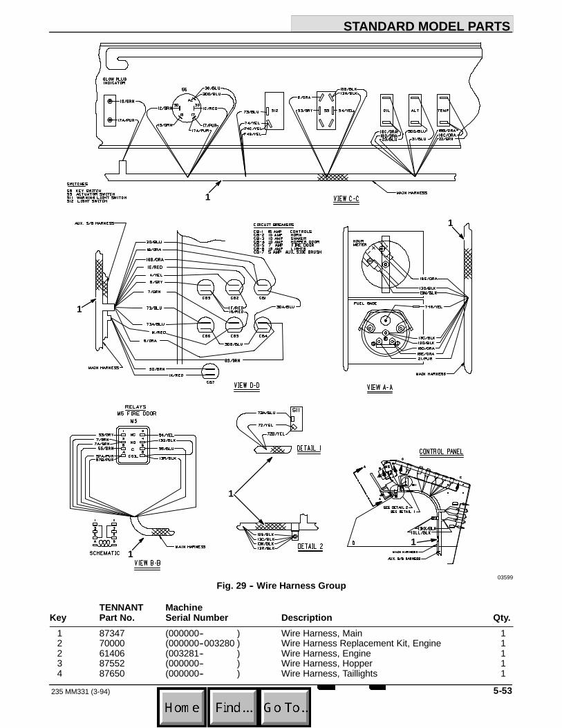
STANDARD MODEL PARTS
5-53235 MM331 (3-94)
11
1
1
1
1
03599Fig. 29 -- Wire Harness Group
TENNANT MachineKey Part No. Serial Number Description Qty.
1 87347 (000000-- ) Wire Harness, Main 12 70000 (000000--003280 ) Wire Harness Replacement Kit, Engine 12 61406 (003281-- ) Wire Harness, Engine 13 87552 (000000-- ) Wire Harness, Hopper 14 87650 (000000-- ) Wire Harness, Taillights 1

STANDARD MODEL PARTS
235 MM331 (3--93)5-54
2
11
3
1
4
06968Fig. 30 -- Labels Group
TENNANT MachineKey Part No. Serial Number Description Qty.
1 87640 (000000-- ) Label Kit, Information and Hazard 12 87639 (000000-- ) Label Kit, Operation 13 08885 (000000-- ) Label, Warning, Emissions 14 87535 (000000-- ) Label, Lintel, 235D 1
87956 (000000-- ) Label, Replacement Kit, Diesel 1

OPTIONS
6-1235 MM331 (3-94)
SECTION 6CONTENTS
PageORDERING REPAIR PARTS 6-3. . . . . . . . . . . . . . .Fig. 1 -- Cab Kit 6-4. . . . . . . . . . . . . . . . . . . . . . . . . . .Fig. 2 -- Overhead Guard Kit 6-5. . . . . . . . . . . . . . . .Fig. 3 -- Revolving Light Kit, Overhead Guard 6-6.Fig. 4 -- Revolving Light Kit, Shroud 6-7. . . . . . . . . .Fig. 5 -- Demo Kit 6-8. . . . . . . . . . . . . . . . . . . . . . . . . .Fig. 6 -- Foam Filled Tire Kit 6-8. . . . . . . . . . . . . . . . .Fig. 7 -- Adjustable Seat Kit 6-9. . . . . . . . . . . . . . . . .Fig. 8 -- Oil Drain Kit 6-10. . . . . . . . . . . . . . . . . . . . . . .Fig. 9 -- Auxiliary Side Brush
Electrical Group 6-11. . . . . . . . . . . . . . .Fig. 10 -- Auxiliary Side Brush Group 6-12. . . . . . . . .Fig. 11 -- Auxiliary Side Brush
Hydraulic Hose Group 6-14. . . . . . . . . .
NOTE: Section 6, Options lists repair parts of theavailable options.
OPTIONS
235 MM331 (3--93)6-2

OPTIONS
6-3235 MM331 (3--93)
ORDERING REPAIR PARTSThe components used in this machine have beencarefully selected for performance and safety. Useonly TENNANT specified or equivalent parts.
To receive prompt service in filling of your partsorders, please direct all orders for parts withTENNANT part numbers to the TENNANT, and allorders for parts with vendor part numbers to the localsupplier of the respective vendor.
When ordering parts, please furnish all of thefollowing information:
1. Machine model number - shown on the machinedata plate.
SER.NO.GVW. LBS. KG.
TENNANT COMPANYMINNEAPOLIS, MINN USA
2. Machine serial number - shown on the machinedata plate.
3. Power source - gasoline, LPG, diesel, electric.
4. Company name.
5. Shipping address.
6. Billing address.
7. Name, first and last - of person ordering parts.
8. Telephone number.
9. Purchase order number.
10. Part number, description, and quantity - of eachitem on the order.
11. Customer ID Number.
Do not order parts by key number or the figurenumber of the illustrated parts. Indented itemsindicate parts of assemblies. Standard hardware isfurnished only when part of a purchased assembly.Please get hardware from a local hardware supplier.
If the old part cannot be identified, send it to us withthe quantity needed specified on the order.
Any claim for loss or damage to a shipment in transitshould be filed promptly against the transportationcompany making the delivery. Shipments will becomplete unless the packing list or order ack-nowledgement indicate items back ordered.
If parts received are suspected to be incorrect ordefective, please write, wire, or phone the TENNANTrepresentative from whom you ordered the part. Theywill give authorization for return and/or handlereplacement shipments when required.
SERIAL NUMBER INFORMATION EXPLANATIONSerial number listings are shown to indicate on whichmachines each part can be used. These listings areexplained by the following examples:
(000000-- ) The part can be used on all machines.
(003342-- ) The part can be used on all machinesbeginning with the serial number listed.
(000000--004320) The part can be used on allmachines up to and including serial number listed.
(004321--005678) The part can be used on allmachines between and including the serial numberslisted.
Where xxxxxx’s are listed in place of a serial number,it indicates a change was made but the exact serialnumber had not been established when the catalogwent to press.
SI UNITS OF MEASURE(INTERNATIONAL SYSTEM)Metric equivalents have been included, whereapplicable, throughout this parts catalog.
FASTENER STRENGTH IDENTIFICATIONFasteners required to have high--strength qualitiesequivalent to SAE Grade 8 are identified throughoutthis catalog by the description GR 8. Unless identifiedby this description, all standard fasteners are SAEGrade 5.
(Specifications and design subject to change withoutnotice.)
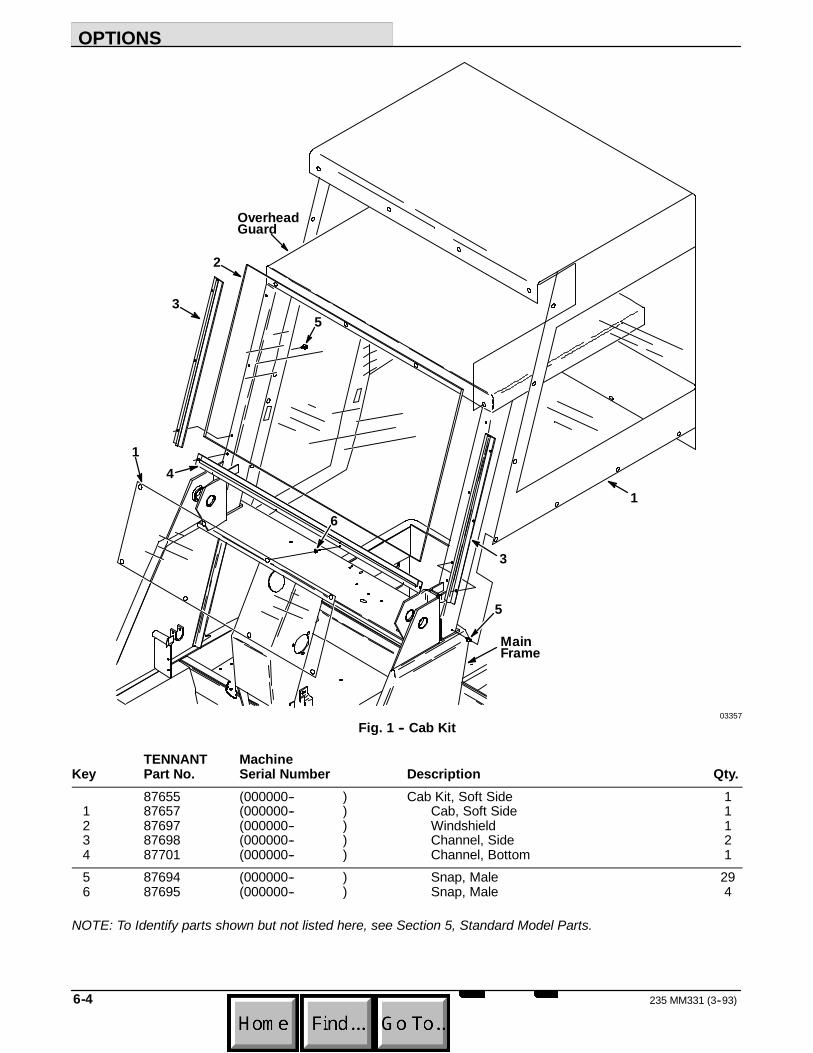
OPTIONS
235 MM331 (3--93)6-4
6
4
3
1
5
MainFrame
3
2
5
1
OverheadGuard
03357Fig. 1 -- Cab Kit
TENNANT MachineKey Part No. Serial Number Description Qty.
87655 (000000-- ) Cab Kit, Soft Side 11 87657 (000000-- ) Cab, Soft Side 12 87697 (000000-- ) Windshield 13 87698 (000000-- ) Channel, Side 24 87701 (000000-- ) Channel, Bottom 15 87694 (000000-- ) Snap, Male 296 87695 (000000-- ) Snap, Male 4
NOTE: To Identify parts shown but not listed here, see Section 5, Standard Model Parts.

OPTIONS
6-5235 MM331 (3--93)
3
1
MainFrame
2
4
4
03355Fig. 2 -- Overhead Guard Kit
TENNANT MachineKey Part No. Serial Number Description Qty.
87829 (000000-- ) Guard Kit, Overhead 11 87450 (000000-- ) Guard, Overhead 12 87742 (000000-- ) Molding, Rigid 23 62595--21 (000000-- ) Molding, Rigid 14 36328 (000000-- ) Washer, Belleville 2
NOTE: To Identify parts shown but not listed here, see Section 5, Standard Model Parts.
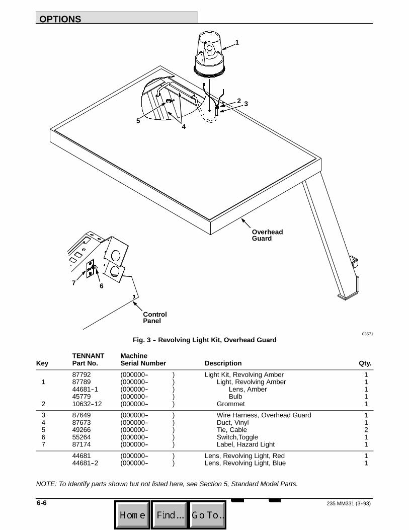
OPTIONS
235 MM331 (3--93)6-6
ControlPanel
OverheadGuard
54
7 6
1
2 3
03571Fig. 3 -- Revolving Light Kit, Overhead Guard
TENNANT MachineKey Part No. Serial Number Description Qty.
87792 (000000-- ) Light Kit, Revolving Amber 11 87789 (000000-- ) Light, Revolving Amber 1
44681--1 (000000-- ) Lens, Amber 145779 (000000-- ) Bulb 1
2 10632--12 (000000-- ) Grommet 13 87649 (000000-- ) Wire Harness, Overhead Guard 14 87673 (000000-- ) Duct, Vinyl 15 49266 (000000-- ) Tie, Cable 26 55264 (000000-- ) Switch,Toggle 17 87174 (000000-- ) Label, Hazard Light 1
44681 (000000-- ) Lens, Revolving Light, Red 144681--2 (000000-- ) Lens, Revolving Light, Blue 1
NOTE: To Identify parts shown but not listed here, see Section 5, Standard Model Parts.
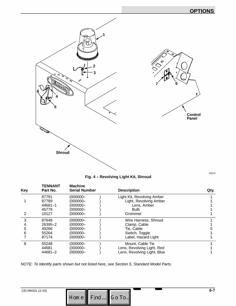
OPTIONS
6-7235 MM331 (3--93)
23
1
67
5
4
Shroud
ControlPanel
8
03570Fig. 4 -- Revolving Light Kit, Shroud
TENNANT MachineKey Part No. Serial Number Description Qty.
87791 (000000-- ) Light Kit, Revolving Amber 11 87789 (000000-- ) Light, Revolving Amber 1
44681--1 (000000-- ) Lens, Amber 145779 (000000-- ) Bulb 1
2 10127 (000000-- ) Grommet 13 87649 (000000-- ) Wire Harness, Shroud 14 26395--2 (000000-- ) Clamp, Cable 15 49266 (000000-- ) Tie, Cable 56 55264 (000000-- ) Switch, Toggle 17 87174 (000000-- ) Label, Hazard Light 18 55248 (000000-- ) Mount, Cable Tie 1
44681 (000000-- ) Lens, Revolving Light, Red 144681--2 (000000-- ) Lens, Revolving Light, Blue 1
NOTE: To Identify parts shown but not listed here, see Section 5, Standard Model Parts.

OPTIONS
235 MM331 (3--93)6-8
MainFrame
2
1
3
4
03362Fig. 5 -- Demo Kit
TENNANT MachineKey Part No. Serial Number Description Qty.
87790 (000000-- ) Demo Kit 11 87083 (000000--001045) Bracket, Replacement Kit, Rear (set of 2) 12 45079 (000000-- ) Bracket, Tie--Down 23 45079 (001046-- ) Bracket, Tie--Down 24 87462 (000000-- ) Knob 3
1
03581Fig. 6 -- Foam Filled Tire Kit
TENNANT MachineKey Part No. Serial Number Description Qty.
1 87432 (000000-- ) Tire and Wheel Assembly, Foam Filled 1
NOTE: To Identify parts shown but not listed here, see Section 5, Standard Model Parts.

OPTIONS
6-9235 MM331 (3--93)
2
3 4
1
2
2
2
08660Fig. 7 -- Adjustable Seat Kit
TENNANT MachineKey Part No. Serial Number Description Qty.
48685 (000000-- ) Adjustable Seat Kit 11 66099 (000000-- ) Plate, Seat Support 12 52615 (000000-- ) Spacer, Seat Adjuster 43 51459 (000000-- ) Adjuster, Seat 14 51458 (000000-- ) Adjuster Assembly, Seat 1

OPTIONS
235 MM331 (3--93)6-10
2
3
4
1
06917Fig. 8 -- Oil Drain Kit
TENNANT MachineKey Part No. Serial Number Description Qty.
48571 (000000-- ) Oil Drain Kit 11 97890 (000000-- ) Hose 12 60453 (000000-- ) Washer, Brass 23 48572 (000000-- ) Fitting, Bandjo 14 97891 (000000-- ) Fitting, Plug 1

OPTIONS
6-11235 MM331 (3-94)
1
23
45
06853Fig. 9 -- Auxiliary Side Brush Electrical Group
TENNANT MachineKey Part No. Serial Number Description Qty.
1 35304 (000000-- ) Label, Brush Control 12 65560 (000000-- ) Switch, Rocker, DPDT 23 57807 (000000-- ) Cover, Rocker Switch Seal 24 27920 (000000-- ) Breaker, Circuit, 5A 15 57751 (000000-- ) Boot, Circuit Breaker 1

OPTIONS
235 MM331 (3-94)6-12
1
1
2
3
3
5
6
7 8
9
10
11
12
131415
1617
18
19
41
20
2122
22
23
23
24
25
2628
293031
32
34
35363738
3940
40
33
3327
27
4
4
FromControlValve
To StandardSide Brush
From Backof Hopper
From Backof Hopper
Fig. 10 -- Auxiliary Side Brush Group

OPTIONS
6-13235 MM331 (3-94)
06854Fig. 10 -- Auxiliary Side Brush Group
TENNANT MachineKey Part No. Serial Number Description Qty.
1 43499 (000000-- ) Bracket 22 48582 (000000-- ) Bracket, Bulkhead 13 48580 (000000-- ) Bracket 24 06678 (000000-- ) Fitting, Straight 25 48556 (000000-- ) Cross Member, Front 16 35273 (000000-- ) Pin, Hitch 17 35278 (000000-- ) Pin, Hitch 18 51534 (000000-- ) Pin, Clevis 19 35280 (000000-- ) Seal, Foam Rubber 1
10 34219 (000000-- ) Insulation, Foam 111 35279 (000000-- ) Cover, Actuator 112 87444 (000000-- ) Actuator 113 82229 (000000-- ) Sleeve 214 35274 (000000-- ) Lever, Actuator 115 48567 (000000-- ) Pivot, Brush Arm 116 45097 (000000-- ) Bearing 217 15173 (000000-- ) Pin, Clevis 118 48581 (000000-- ) Cable 119 28804 (000000-- ) Motor, Hydraulic 120 06474A (000000-- ) Pin, Clevis 121 48584 (000000-- ) Bracket, Motor 122 58494 (000000-- ) Stud, Ball 223 64595 (000000-- ) Clip, Spring 224 31182 (000000-- ) Spring, Gas 125 57984 (000000-- ) Fitting, Straight 226 87677 (000000-- ) Sleeve, Nylon 127 34413 (000000-- ) Coupling, Male 228 49266 (000000-- ) Tie, Cable 629 87439 (000000-- ) Deflecter 130 87418 (000000-- ) Hub, Side Brush 131 41178 (000000-- ) Washer 132 41185 (000000-- ) Washer, Belleville 133 34414 (000000-- ) Coupling, Female 234 48587 (000000-- ) Actuator 135 48557 (000000-- ) Arm, Extended Reach 136 02965 (000000-- ) Sleeve 137 43560 (000000-- ) Clamp, Cable 138 23683 (000000-- ) Pin, Clevis 139 10632 (000000-- ) Grommet 140 82621 (000000-- ) Fitting, Bulkhead 241 23683 (000000-- ) Pin, Clevis 1
49287 (000000-- ) Clamp, Cable 127184 (000000-- ) Blade, Connector 248563 (000000-- ) Wire Harness, Aux Side Brush 1

OPTIONS
235 MM331 (3-94)6-14
1
2 3
4
06852Fig. 11 -- Auxiliary Side Brush Hydraulic Hose Group
TENNANT MachineKey Part No. Serial Number Description Qty.
1 57967 (000000-- ) Hose, Hydraulic 12 48617 (000000-- ) Hose, Hydraulic 13 57947 (000000-- ) Hose, Hydraulic 14 19634 (000000-- ) Hose, Hydraulic 1

HYDRAULIC COMPONENTS
7-1235 MM331 (3-94)
SECTION 7CONTENTS
PageORDERING REPAIR PARTS 7-3. . . . . . . . . . . . . . .Fig. 1 -- Hydraulic Motor Breakdown, 87417 7-4. . .Fig. 2 -- Hydraulic Motor Breakdown, 87475 7-5. . .Fig. 3 -- Hydraulic Valve Breakdown, 87409 7-6. . .Fig. 4 -- Hydraulic Pump Breakdown, 87734 7-7. . .Fig. 5 -- Hydraulic Lift Cylinder Breakdown,
87055 7-8. . . . . . . . . . . . . . . . . . . . . . . .Fig. 6 -- Hydraulic Lift Cylinder Breakdown,
48575 7-9. . . . . . . . . . . . . . . . . . . . . . . .Fig. 7 -- Hydraulic Lift Cylinder Breakdown,
65223 7-10. . . . . . . . . . . . . . . . . . . . . . . .Fig. 8 -- Hydraulic Pump Breakdown, 87451 7-11. . .Fig. 9 -- Hydraulic Motor Breakdown, 28804 7-12. . .
NOTE: Section 7, Hydraulic Components, lists therepair parts for each of the repairable hydrauliccomponents.

HYDRAULIC COMPONENTS
235 MM331 (3--93)7-2
HYDRAULIC COMPONENTS
7-3235 MM331 (3--93)
ORDERING REPAIR PARTSThe components used in this machine have beencarefully selected for performance and safety. Useonly TENNANT specified or equivalent parts.
To receive prompt service in filling of your partsorders, please direct all orders for parts withTENNANT part numbers to the TENNANT, and allorders for parts with vendor part numbers to the localsupplier of the respective vendor.
When ordering parts, please furnish all of thefollowing information:
1. Machine model number - shown on the machinedata plate.
SER.NO.GVW. LBS. KG.
TENNANT COMPANYMINNEAPOLIS, MINN USA
2. Machine serial number - shown on the machinedata plate.
3. Power source - gasoline, LPG, diesel, electric.
4. Company name.
5. Shipping address.
6. Billing address.
7. Name, first and last - of person ordering parts.
8. Telephone number.
9. Purchase order number.
10. Part number, description, and quantity - of eachitem on the order.
11. Customer ID Number.
Do not order parts by key number or the figurenumber of the illustrated parts. Indented itemsindicate parts of assemblies. Standard hardware isfurnished only when part of a purchased assembly.Please get hardware from a local hardware supplier.
If the old part cannot be identified, send it to us withthe quantity needed specified on the order.
Any claim for loss or damage to a shipment in transitshould be filed promptly against the transportationcompany making the delivery. Shipments will becomplete unless the packing list or order ack-nowledgement indicate items back ordered.
If parts received are suspected to be incorrect ordefective, please write, wire, or phone the TENNANTrepresentative from whom you ordered the part. Theywill give authorization for return and/or handlereplacement shipments when required.
SERIAL NUMBER INFORMATION EXPLANATIONSerial number listings are shown to indicate on whichmachines each part can be used. These listings areexplained by the following examples:
(000000-- ) The part can be used on all machines.
(003342-- ) The part can be used on all machinesbeginning with the serial number listed.
(000000--004320) The part can be used on allmachines up to and including serial number listed.
(004321--005678) The part can be used on allmachines between and including the serial numberslisted.
Where xxxxxx’s are listed in place of a serial number,it indicates a change was made but the exact serialnumber had not been established when the catalogwent to press.
SI UNITS OF MEASURE(INTERNATIONAL SYSTEM)Metric equivalents have been included, whereapplicable, throughout this parts catalog.
FASTENER STRENGTH IDENTIFICATIONFasteners required to have high--strength qualitiesequivalent to SAE Grade 8 are identified throughoutthis catalog by the description GR 8. Unless identifiedby this description, all standard fasteners are SAEGrade 5.
(Specifications and design subject to change withoutnotice.)

HYDRAULIC COMPONENTS
235 MM331 (3--93)7-4
1
1 11
1
2
3
4
5 6
7 8 9 10
11
12
03604Fig. 1 -- Hydraulic Motor Breakdown, 87417
TENNANT ManufactureKey Part No. Serial Number Description Qty.
87417 (000000-- ) Motor, Hydraulic 11 02643 (000000-- ) Seal Kit 12 02644 (000000-- ) Shaft And Bearing Kit 13 87784 (000000-- ) Drive 14 87785 (000000-- ) Geroler 15 57370 (000000-- ) Valve Drive 16 02646 (000000-- ) Valve Plate 17 02647 (000000-- ) Valve 18 57373 (000000-- ) Balance Ring 19 57374 (000000-- ) Pin 2
10 57375 (000000-- ) Spring 211 38315 (000000-- ) Key 112 38490 (000000-- ) Nut 1

HYDRAULIC COMPONENTS
7-5235 MM331 (3--93)
1
2
2
2
3
4
5
6 7
8
03563Fig. 2 -- Hydraulic Motor Breakdown, 87475
TENNANT ManufactureKey Part No. Serial Number Description Qty.
87475 (000000-- ) Motor, Hydraulic (Replaced by 28804) 11 34174 (000000-- ) Flange, Mounting 12 47649 (000000-- ) Seal Kit 13 87662 (000000-- ) Shaft, Output 14 34176 (000000-- ) Drive 15 87663 (000000-- ) Geroter 16 16695 (000000-- ) Race, Thrust 17 45628 (000000-- ) Bearing, Thrust 18 00500--15 (000000-- ) Key, Woodruff 1

HYDRAULIC COMPONENTS
235 MM331 (3--93)7-6
3
2
1
03480Fig. 3 -- Hydraulic Valve Breakdown, 87409
TENNANT ManufactureKey Part No. Serial Number Description Qty.
87409 (000000-- ) Valve, Hydraulic 11 01666 (000000-- ) Seal Kit 12 87754 (000000-- ) Relief Valve Kit 13 01669 (000000-- ) Detent Kit 1

HYDRAULIC COMPONENTS
7-7235 MM331 (3--93)
7
83
2
7
6 1
1
47 5
03605Fig. 4 -- Hydraulic Pump Breakdown, 87734
TENNANT ManufactureKey Part No. Serial Number Description Qty.
87734 (000000-- ) Pump, Hydraulic 11 87266 (000000-- ) Relief Valve Kit 22 33296 (000000-- ) Valve Plate Kit 13 33298 (000000-- ) Saddle Kit 14 33299 (000000-- ) Control Kit 15 33303 (000000-- ) Rotating Group Kit 16 33304 (000000-- ) Shaft And Bearing Kit 17 33305 (000000-- ) Seal Kit 18 00912 (000000-- ) Key, Square 1

HYDRAULIC COMPONENTS
235 MM331 (3--93)7-8
2
3
1
1
1
08680Fig. 5 -- Hydraulic Lift Cylinder Breakdown, 87055
TENNANT ManufactureKey Part No. Serial Number Description Qty.
87055 (000000-- ) Cylinder, Hydraulic (Replaced by 48575) 11 87744 (000000-- ) Seal Kit 12 87850 (000000-- ) Pin, Clevis 13 87851 (000000-- ) Pin, Hair Cotter 1

HYDRAULIC COMPONENTS
7-9235 MM331 (3--93)
2
3
1
1
1
08685Fig. 6 -- Hydraulic Lift Cylinder Breakdown, 48575
TENNANT ManufactureKey Part No. Serial Number Description Qty.
48575 (000000-- ) Cylinder, Hydraulic 11 48577 (000000-- ) Seal Kit 12 87850 (000000-- ) Pin, Clevis 13 87851 (000000-- ) Pin, Hair Cotter 1

HYDRAULIC COMPONENTS
235 MM331 (3-94)7-10
2
3
1
1
1
09727Fig. 7 -- Hydraulic Lift Cylinder Breakdown, 65223
TENNANT ManufactureKey Part No. Serial Number Description Qty.
65223 (000000-- ) Cylinder, Hydraulic 11 48577 (000000-- ) Seal Kit 12 87850 (000000-- ) Pin, Clevis 13 87851 (000000-- ) Pin, Hair Cotter 1
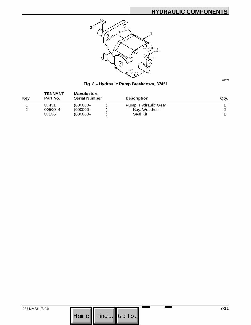
HYDRAULIC COMPONENTS
7-11235 MM331 (3-94)
21
2
03672Fig. 8 -- Hydraulic Pump Breakdown, 87451
TENNANT ManufactureKey Part No. Serial Number Description Qty.
1 87451 (000000-- ) Pump, Hydraulic Gear 12 00500--4 (000000-- ) Key, Woodruff 2
87156 (000000-- ) Seal Kit 1

HYDRAULIC COMPONENTS
235 MM331 (3-94)7-12
1
2
2
2
3
4
5
6
05608Fig. 9 -- Hydraulic Motor Breakdown, 28804
TENNANT ManufactureKey Part No. Serial Number Description Qty.
28804 (000000-- ) Motor, Hydraulic 11 31354 (000000-- ) Flange, Mounting 12 28835 (000000-- ) Seal Kit 13 87662 (000000-- ) Shaft, Output 14 34176 (000000-- ) Drive 15 50186 (000000-- ) Geroter Set 16 00500--15 (000000-- ) Key, Woodruff 1

ENGINE PARTS, DIESEL
8-1235 MM331 (3--93)
SECTION 8CONTENTS
PageORDERING REPAIR PARTS 8-3. . . . . . . . . . . . . . .Fig. 1 -- Crankcase Group 8-4. . . . . . . . . . . . . . . . . .Fig. 2 -- Gear Case Group 8-6. . . . . . . . . . . . . . . . .Fig. 3 -- Cylinder Head Group 8-8. . . . . . . . . . . . . . .Fig. 4 -- Bearing Case Group 8-9. . . . . . . . . . . . . . .Fig. 5 -- Breather Group 8-10. . . . . . . . . . . . . . . . . . .Fig. 6 -- Air Cleaner and Manifolds Group 8-12. . . .Fig. 7 -- Valve, Rocker Arm Group 8-14. . . . . . . . . . .Fig. 8 -- Head Cover Group 8-15. . . . . . . . . . . . . . . . .Fig. 9 -- Camshaft Group 8-16. . . . . . . . . . . . . . . . . . .Fig. 10 -- Piston, Crankshaft Group 8-18. . . . . . . . . .Fig. 11 -- Flywheel Group 8-20. . . . . . . . . . . . . . . . . . .Fig. 12 -- Injection Pump Group 8-21. . . . . . . . . . . . .Fig. 13 -- Governor Group 8-22. . . . . . . . . . . . . . . . . .Fig. 14 -- Radiator Group 8-24. . . . . . . . . . . . . . . . . . .
NOTE: Section 8, Engine Parts, Diesel, lists therepair parts for the diesel engine, TENNANT Part No.87501.

ENGINE PARTS, DIESEL
235 MM331 (3--93)8-2

ENGINE PARTS, DIESEL
8-3235 MM331 (3--93)
ORDERING REPAIR PARTSThe components used in this machine have beencarefully selected for performance and safety. Useonly TENNANT specified or equivalent parts.
To receive prompt service in filling of your partsorders, please direct all orders for parts withTENNANT part numbers to the TENNANT, and allorders for parts with vendor part numbers to the localsupplier of the respective vendor.
When ordering parts, please furnish all of thefollowing information:
1. Machine model number - shown on the machinedata plate.
SER.NO.GVW. LBS. KG.
TENNANT COMPANYMINNEAPOLIS, MINN USA
2. Machine serial number - shown on the machinedata plate.
3. Power source - gasoline, LPG, diesel, electric.
4. Company name.
5. Shipping address.
6. Billing address.
7. Name, first and last - of person ordering parts.
8. Telephone number.
9. Purchase order number.
10. Part number, description, and quantity - of eachitem on the order.
11. Customer ID Number.
Do not order parts by key number or the figurenumber of the illustrated parts. Indented itemsindicate parts of assemblies. Standard hardware isfurnished only when part of a purchased assembly.Please get hardware from a local hardware supplier.
If the old part cannot be identified, send it to us withthe quantity needed specified on the order.
Any claim for loss or damage to a shipment in transitshould be filed promptly against the transportationcompany making the delivery. Shipments will becomplete unless the packing list or order ack-nowledgement indicate items back ordered.
If parts received are suspected to be incorrect ordefective, please write, wire, or phone the TENNANTrepresentative from whom you ordered the part. Theywill give authorization for return and/or handlereplacement shipments when required.
SERIAL NUMBER INFORMATION EXPLANATIONSerial number listings are shown to indicate on whichmachines each part can be used. These listings areexplained by the following examples:
(000000-- ) The part can be used on all machines.
(003342-- ) The part can be used on all machinesbeginning with the serial number listed.
(000000--004320) The part can be used on allmachines up to and including serial number listed.
(004321--005678) The part can be used on allmachines between and including the serial numberslisted.
Where xxxxxx’s are listed in place of a serial number,it indicates a change was made but the exact serialnumber had not been established when the catalogwent to press.
SI UNITS OF MEASURE(INTERNATIONAL SYSTEM)Metric equivalents have been included, whereapplicable, throughout this parts catalog.
FASTENER STRENGTH IDENTIFICATIONFasteners required to have high--strength qualitiesequivalent to SAE Grade 8 are identified throughoutthis catalog by the description GR 8. Unless identifiedby this description, all standard fasteners are SAEGrade 5.
(Specifications and design subject to change withoutnotice.)

ENGINE PARTS, DIESEL
235 MM331 (3--93)8-4
1
2
3
4
5
6
7
8
9
1011
1213
1415
16
17
18
19
2021
2223
26
27
28
2930
262425
5
Fig. 1 -- Crankcase Group

ENGINE PARTS, DIESEL
8-5235 MM331 (8--95)
03606Fig. 1 -- Crankcase Group
TENNANT Kubota EngineKey Part No. Part Number Serial Number Description Qty.
1 15903--0101--0 (000000-- ) Crankcase, Complete 12 06311--75040 (000000-- ) Plug, Expansion 13 51331 15321--9626--0 (000000-- ) Cap, Sealing 14 15901--3363--0 (000000-- ) Plug, Blind 15 39183 15221--3363--0 (000000-- ) Plug, Pin 56 14301--3363--0 (000000-- ) Plug, Pin 17 39060 15221--3365--0 (000000-- ) Pin, Pipe 18 39063 15221--3370--0 (000000-- ) O--Ring 19 15231--3396--0 (000000-- ) Pin, Pipe 2
10 15231--3395--0 (000000-- ) Pin, Pipe 111 04811--10100 (000000-- ) O--Ring 112 15271--3395--0 (000000-- ) Pin, Pipe 113 04811--10120 (000000-- ) O--Ring 114 15261--7391--0 (000000-- ) Cover, Water 115 40409 01023--50618 (000000-- ) Bolt 216 15271--0576--0 (000000-- ) Pipe, Breather Inlet 117 51342 15901--0231--0 (000000-- ) Liner, Cylinder 218 12925 15272--0161--0 (000000-- ) Oil Pan 119 12924 15271--0162--0 (000000-- ) Gasket, Oil Pan 120 01053--50655 (000000-- ) Bolt 821 39065 04512--60060 (000000-- ) Washer, Spring 822 15261--3375--0 (000000-- ) Plug 123 15109--3366--0 (000000-- ) Gasket 124 15271--0471--0 (000000-- ) Cover, Crankcase 125 12923 15271--0472--0 (000000-- ) Gasket, Crankcase Cover 126 40409 01023--50618 (000000-- ) Bolt 1227 12922 15271--3211--0 (000000-- ) Filter, Oil 128 40204 04811--00120 (000000-- ) O--Ring 129 01153--50818 (000000-- ) Bolt 130 39097 04512--60080 (000000-- ) Washer, Spring 1
12921 19215--9905--0 (000000-- ) Gasket Kit, Overhaul 130106 07916--2454--0 (000000-- ) Gasket Set, Upper 130107 07916--2455--0 (000000-- ) Gasket Set, Lower 1

ENGINE PARTS, DIESEL
235 MM331 (3--93)8-6
1
2
34
5
6
8
9
10
11
12
13
1415
16
17
18
19
20
21
22
2324
2526
2728
29
30
31 32
1313
7
13
29
Fig. 2 -- Gear Case Group
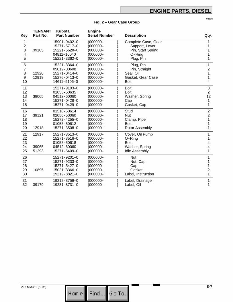
ENGINE PARTS, DIESEL
8-7235 MM331 (8--95)
03608Fig. 2 -- Gear Case Group
TENNANT Kubota EngineKey Part No. Part Number Serial Number Description Qty.
1 15901--0402--0 (000000-- ) Complete Case, Gear 12 15271--5717--0 (000000-- ) Support, Lever 13 39105 15221--5628--0 (000000-- ) Pin, Start Spring 14 04811--10040 (000000-- ) O--Ring 15 15221--3362--0 (000000-- ) Plug, Pin 16 15221--3364--0 (000000-- ) Plug, Pin 17 05012--00608 (000000-- ) Pin, Straight 28 12920 15271--0414--0 (000000-- ) Seal, Oil 19 12919 15276--0413--0 (000000-- ) Gasket, Gear Case 1
10 14611--9106--0 (000000-- ) Bolt 411 15271--9103--0 (000000-- ) Bolt 312 01053--50635 (000000-- ) Bolt 213 39065 04512--60060 (000000-- ) Washer, Spring 1214 15271--0428--0 (000000-- ) Cap 115 15271--0429--0 (000000-- ) Gasket, Cap 116 01518--50614 (000000-- ) Stud 217 39121 02056--50060 (000000-- ) Nut 218 15272--4255--0 (000000-- ) Clamp, Pipe 119 01053--50612 (000000-- ) Bolt 120 12918 15271--3508--0 (000000-- ) Rotor Assembly 121 12917 15271--3513--0 (000000-- ) Cover, Oil Pump 122 15271--3516--0 (000000-- ) O--Ring 123 01053--50618 (000000-- ) Bolt 424 39065 04512--60060 (000000-- ) Washer, Spring 425 51293 15271--5409--0 (000000-- ) Idle Assembly 126 15271--9201--0 (000000-- ) Nut 127 15271--9233--0 (000000-- ) Nut, Cap 128 15271--5427--0 (000000-- ) Cap 129 10895 15021--3366--0 (000000-- ) Gasket 230 19212--8821--0 (000000-- ) Label, Instruction 131 19212--8759--0 (000000-- ) Label, Drainage 132 39179 19231--8731--0 (000000-- ) Label, Oil 1

ENGINE PARTS, DIESEL
235 MM331 (8--95)8-8
12
34 56
78
910
11
12
13
14
15 16
17
1819
20
11 16
03607Fig. 3 -- Cylinder Head Group
TENNANT Kubota EngineKey Part No. Part Number Serial Number Description Qty.
1 15271--0175--0 (000000-- ) Hook, Engine 12 01123--50828 (000000-- ) Bolt 13 15901--0304--0 (000000-- ) Cylinder Head, Complete 14 15261--0337--0 (000000-- ) Cap, Sealing 35 51331 15321--9626--0 (000000-- ) Cap, Sealing 16 39088 15261--9601--0 (000000-- ) Plug 27 50998 15261--1354--0 (000000-- ) Guide, Inlet Valve 28 50999 15261--1356--0 (000000-- ) Guide, Exhaust Valve 29 15271--0337--0 (000000-- ) Cover 1
10 51286 15271--0338--0 (000000-- ) Gasket, Cover 111 40409 01023--50618 (000000-- ) Bolt 312 39065 04512--60060 (000000-- ) Washer, Spring 113 01513--50620 (000000-- ) Stud 114 39121 02056--50060 (000000-- ) Nut 115 19215--0345--0 (000000-- ) Bolt, Cylinder Head 816 19215--0341--2 (000000-- ) Stud, Cylinder Head 217 19215--0351--2 (000000-- ) Nut, Cylinder Head 218 51343 15901--0331--4 (000000-- ) Gasket, Cylinder Head 119 51345 15901--0332--0 (000000-- ) Shim, Cylinder Head Gasket --20 87925 14301--7311--0 (000000-- ) Cock, Drain 1

ENGINE PARTS, DIESEL
8-9235 MM331 (8--95)
2
3
4
567
8
910
1
11
3
2
5
03609Fig. 4 -- Bearing Case Group
TENNANT Kubota EngineKey Part No. Part Number Serial Number Description Qty.
1 15274--0409--0 (000000-- ) Case, Main Bearing 12 15261--0454--0 (000000-- ) Bolt, Bearing Case 43 50995 15261--0457--0 (000000-- ) Washer, Bearing Case 44 15271--0436--0 (000000-- ) Gasket, Bearing Case 15 01023--50625 (000000-- ) Bolt 176 19215--0481--0 (000000-- ) Cover, Bearing Case 17 87926 15271--0482--0 (000000-- ) Gasket, Bearing Case Cover 18 87927 19215--0446--0 (000000-- ) Seal, Oil 19 12789 15274--0404--0 (000000-- ) Bearing Assembly, Main 1
10 15261--0456--0 (000000-- ) Bolt, Bearing Case 111 50996 15261--0459--0 (000000-- ) Washer, Bearing Case 1

ENGINE PARTS, DIESEL
235 MM331 (3--93)8-10
1
23
4
5
6
7
89
10
1112
13
14
15
17
18
19
20
2122
23
2425
26
2728 29
32
33
34
29 3130
2118
Fig. 5 -- Breather Group

ENGINE PARTS, DIESEL
8-11235 MM331 (8--95)
03610Fig. 5 -- Breather Group
TENNANT Kubota EngineKey Part No. Part Number Serial Number Description Qty.
1 15271--0541--0 (000000-- ) Cover, Breather 12 15231--0511--0 (000000-- ) Breather 13 87928 (000000-- ) Gasket Set, Breather 13 87929 15231--0513--0 (000000-- ) Gasket, Breather 24 87930 15231--0567--0 (000000-- ) Element, Breather 15 15271--0551--0 (000000-- ) Pipe, Breather 16 41973 01023--50616 (000000-- ) Bolt 27 01518--50614 (000000-- ) Stud 28 39121 02056--50060 (000000-- ) Nut 29 39065 04512--60060 (000000-- ) Washer, Spring 2
10 15271--0558--0 (000000-- ) Clamp, Pipe 111 87870 15241--3209--0 (000000-- ) Filter, Oil 112 12916 15241--3229--0 (000000-- ) Pipe, Joint 113 51284 15261--3607--0 (000000-- ) Valve, Relief 114 04810--00150 (000000-- ) O--Ring 115 39161 15221--3314--0 (000000-- ) Plug, Oil Filter 116 39162 04811--50300 (000000-- ) O--Ring 117 15271--5414--0 (000000-- ) Support 118 15271--5415--0 (000000-- ) Gasket, Support 119 01518--50614 (000000-- ) Stud 420 39121 02056--50060 (000000-- ) Nut 421 39065 04512--60060 (000000-- ) Washer, Spring 622 15271--9103--0 (000000-- ) Bolt 223 15272--3641--0 (000000-- ) Gauge, Oil Level 124 15901--5402--0 (000000-- ) Apparatus, Fuel 125 15271--5417--0 (000000-- ) Pin 126 15231--5423--0 (000000-- ) Spring 127 15261--5437--0 (000000-- ) Nut, Lock 128 14301--5443--0 (000000-- ) Screw, Set 129 15901--5419--0 (000000-- ) Gasket 230 14301--5442--0 (000000-- ) Cap 131 15261--5422--0 (000000-- ) Nut, Cap 132 19234--8721--0 (000000-- ) Label, Instruction 133 19212--8822--0 (000000-- ) Label, Instruction 134 15901--0427--0 (000000-- ) Support, Spring 1
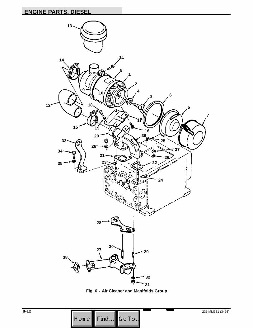
ENGINE PARTS, DIESEL
235 MM331 (3--93)8-12
1
2
34
5
6
7
8
9 10
11
12
13
14
1516
17
18
1920
212223
24
2526
27
28
2930
3132
33
34
35
36
37
38
26
Fig. 6 -- Air Cleaner and Manifolds Group

ENGINE PARTS, DIESEL
8-13235 MM331 (8--95)
03611Fig. 6 -- Air Cleaner and Manifolds Group
TENNANT Kubota EngineKey Part No. Part Number Serial Number Description Qty.
1 19215--1101--2 (000000-- ) Cleaner Assembly, Air 12 87875 19215--1122--0 (000000-- ) Element, Air Cleaner 13 15272--9261--0 (000000-- ) Bolt, Wing 14 87931 15272--9443--0 (000000-- ) Washer, Seal 15 51295 15272--1141--0 (000000-- ) Cover, Baffle 16 87932 15272--1117--0 (000000-- ) Gasket 17 30045 15272--1116--0 (000000-- ) Cover, Air Cleaner 18 19215--8745--0 (000000-- ) Label, Air Cleaner 19 15272--1125--0 (000000-- ) Band, Air Cleaner 1
10 34150--1397--0 (000000-- ) Cushion 111 01123--50830 (000000-- ) Bolt 112 12915 15272--1162--0 (000000-- ) Pipe, Inlet 113 15241--1135--2 (000000-- ) Cap, Air Cleaner 114 15221--1172--0 (000000-- ) Band, Pipe 115 15261--1172--0 (000000-- ) Band, Pipe 116 39094 01123--60816 (000000-- ) Bolt 217 15272--1157--0 (000000-- ) Stay, Air Cleaner 118 01153--50818 (000000-- ) Bolt 219 39097 04512--60080 (000000-- ) Washer, Spring 220 15271--1176--0 (000000-- ) Manifold, Inlet 121 12914 15261--1182--0 (000000-- ) Gasket, Inlet Manifold 122 12913 15261--1183--0 (000000-- ) Gasket, Inlet Manifold 123 01513--50620 (000000-- ) Stud 124 01513--50650 (000000-- ) Stud 125 41973 01023--50616 (000000-- ) Bolt 226 39065 04512--60060 (000000-- ) Washer, Spring 227 12912 15274--1232--0 (000000-- ) Manifold, Exhaust 128 87933 15272--1236--0 (000000-- ) Gasket, Exhaust Manifold 129 15272--9149--0 (000000-- ) Stud 230 15272--9150--0 (000000-- ) Stud 231 39121 02056--50060 (000000-- ) Nut 432 39065 04512--60060 (000000-- ) Washer, Spring 433 15272--0175--0 (000000-- ) Hook, Engine 134 01153--50816 (000000-- ) Bolt 135 39097 04512--60080 (000000-- ) Washer, Spring 136 19212--8824--0 (000000-- ) Label, Instruction 137 39121 02056--50060 (000000-- ) Nut 238 87934 54266--8174--0 (000000-- ) Gasket, Exhaust Manifold 1
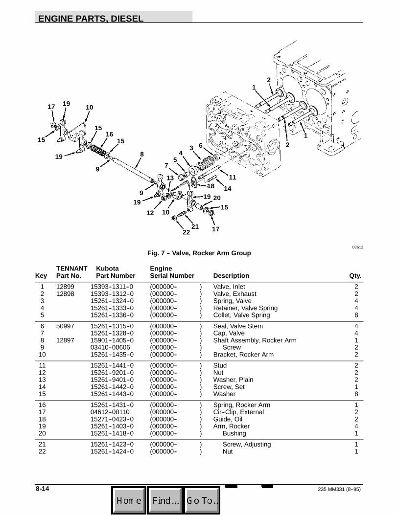
ENGINE PARTS, DIESEL
235 MM331 (8--95)8-14
2
345
6
78
9
10
1
11
12
1314
15
16
17
18
19
20
2122
9
12
17
19
1919
15
1515
10
03612Fig. 7 -- Valve, Rocker Arm Group
TENNANT Kubota EngineKey Part No. Part Number Serial Number Description Qty.
1 12899 15393--1311--0 (000000-- ) Valve, Inlet 22 12898 15393--1312--0 (000000-- ) Valve, Exhaust 23 15261--1324--0 (000000-- ) Spring, Valve 44 15261--1333--0 (000000-- ) Retainer, Valve Spring 45 15261--1336--0 (000000-- ) Collet, Valve Spring 86 50997 15261--1315--0 (000000-- ) Seal, Valve Stem 47 15261--1328--0 (000000-- ) Cap, Valve 48 12897 15901--1405--0 (000000-- ) Shaft Assembly, Rocker Arm 19 03410--00606 (000000-- ) Screw 2
10 15261--1435--0 (000000-- ) Bracket, Rocker Arm 211 15261--1441--0 (000000-- ) Stud 212 15261--9201--0 (000000-- ) Nut 213 15261--9401--0 (000000-- ) Washer, Plain 214 15261--1442--0 (000000-- ) Screw, Set 115 15261--1443--0 (000000-- ) Washer 816 15261--1431--0 (000000-- ) Spring, Rocker Arm 117 04612--00110 (000000-- ) Cir--Clip, External 218 15271--0423--0 (000000-- ) Guide, Oil 219 15261--1403--0 (000000-- ) Arm, Rocker 420 15261--1418--0 (000000-- ) Bushing 121 15261--1423--0 (000000-- ) Screw, Adjusting 122 15261--1424--0 (000000-- ) Nut 1

ENGINE PARTS, DIESEL
8-15235 MM331 (8--95)
2
3
45
67
8
9
10
1
111213
1415
16
17
18
03613Fig. 8 -- Head Cover Group
TENNANT Kubota EngineKey Part No. Part Number Serial Number Description Qty.
1 15271--1451--0 (000000-- ) Cover, Cylinder Head 12 12896 15261--1452--0 (000000-- ) Gasket, Head Cover 13 15261--1462--0 (000000-- ) Nut, Head Cover 24 15261--1464--0 (000000-- ) Washer, Head Cover 25 15261--1463--0 (000000-- ) Gasket, Nut 26 15261--6663--0 (000000-- ) Cover, Decompression Hole 27 15261--6664--0 (000000-- ) Gasket 28 39160 01053--50614 (000000-- ) Bolt 49 15951--6604--0 (000000-- ) Shaft, Decompression 1
10 15261--6635--0 (000000-- ) Bolt, Decompression 211 02056--50050 (000000-- ) Nut 212 04811--00080 (000000-- ) O--Ring 113 15261--6619--0 (000000-- ) Holder, Decompression Wire 114 01053--50612 (000000-- ) Bolt 215 39065 04512--60060 (000000-- ) Washer, Spring 316 39164 15221--6628--0 (000000-- ) Spring, Decompression 117 39169 15221--6641--0 (000000-- ) Bolt 118 19212--8823--0 (000000-- ) Label, Instruction 1

ENGINE PARTS, DIESEL
235 MM331 (3--93)8-16
1
2
3
4
5
6
7
89
11
1314
1516
17
1819
20
21
22
11
10
12
Fig. 9 -- Camshaft Group

ENGINE PARTS, DIESEL
8-17235 MM331 (8--95)
03614Fig. 9 -- Camshaft Group
TENNANT Kubota EngineKey Part No. Part Number Serial Number Description Qty.
1 12895 15261--1555--0 (000000-- ) Tappet 42 15271--1511--0 (000000-- ) Rod, Push 43 15271--1601--0 (000000-- ) Camshaft 14 15261--9688--0 (000000-- ) Plug, Blind 15 15271--1624--0 (000000-- ) Key, Feather 16 15271--1651--0 (000000-- ) Gear, Camshaft 17 15271--1627--0 (000000-- ) Stopper, Camshaft 18 01153--50818 (000000-- ) Bolt 29 39097 04512--60080 (000000-- ) Washer, Spring 2
10 15271--2401--0 (000000-- ) Gear Assembly, Idle 111 15261--2428--0 (000000-- ) Brush, Idle Gear, Std. 211 51282 15261--2498--0 (000000-- ) Brush, Idle Gear, 0.3 Undersize 212 15261--2436--0 (000000-- ) Collar, Idle Gear 113 15261--2437--0 (000000-- ) Collar, Idle Gear 114 15261--2432--0 (000000-- ) Cir--Clip, External 115 15271--2425--0 (000000-- ) Shaft, Idle Gear 116 01123--50820 (000000-- ) Bolt 317 15261--5545--0 (000000-- ) Sleeve, Governor 118 15261--5547--0 (000000-- ) Cir--Clip 119 15261--5569--0 (000000-- ) Case, Governor Ball 120 39523 07715--03205 (000000-- ) Ball 3021 15261--5574--0 (000000-- ) Cir--Clip 122 50970 07715--03217 (000000-- ) Ball 8

ENGINE PARTS, DIESEL
235 MM331 (3--93)8-18
1
2
3
4
5
6
7
8 910
11
12
1314
1516
17
18
19
20
21
4
222221
Fig. 10 -- Piston, Crankshaft Group

ENGINE PARTS, DIESEL
8-19235 MM331 (8--95)
03615Fig. 10 -- Piston, Crankshaft Group
TENNANT Kubota EngineKey Part No. Part Number Serial Number Description Qty.
1 51352 15901--2111--0 (000000-- ) Piston, Std. 21 51353 15901--2191--0 (000000-- ) Piston, 0.5 Oversize 22 51348 15901--2105--0 (000000-- ) Ring, Piston, Std. 22 51351 15901--2109--0 (000000-- ) Ring, Piston, 0.5 Oversize 23 51011 15261--2131--0 (000000-- ) Pin, Piston 24 15261--2133--0 (000000-- ) Cir--Clip, Piston Pin 45 15531--2201--0 (000000-- ) Rod Assembly, Connecting 26 15261--2135--0 (000000-- ) Bushing, Piston Pin, Std. 26 51014 15261--2198--0 (000000-- ) Bushing, Piston Pin, 0.3 Undersize 27 15261--2214--0 (000000-- ) Bolt, Connecting Rod 28 51336 15531--2231--0 (000000-- ) Bearing, Crankpin, Std. 48 15261--2297--0 (000000-- ) Bearing, Crankpin, 0.2 Undersize 48 15261--2298--0 (000000-- ) Bearing, Crankpin, 0.4 Undersize 49 19215--2301--0 (000000-- ) Crankshaft 1
10 15131--0138--0 (000000-- ) Plug, Pin 211 15271--2411--0 (000000-- ) Gear, Crankshaft 112 05712--00515 (000000-- ) Key, Feather 213 15271--2325--0 (000000-- ) Collar, Crankshaft 114 15271--2625--0 (000000-- ) Balancer 115 15261--2336--0 (000000-- ) Nut, Crankshaft 116 15261--2338--2 (000000-- ) Washer, Crankshaft 117 51387 19215--2328--0 (000000-- ) Sleeve, Crankshaft 118 51019 15261--2347--0 (000000-- ) Bearing, Crankshaft, Std. 118 51275 15261--2391--0 (000000-- ) Bearing, Crankshaft, 0.2 Undersize 118 12788 15261--2392--0 (000000-- ) Bearing, Crankshaft, 0.4 Undersize 119 30057 15274--2348--0 (000000-- ) Bearing, Crankshaft, Std. 219 51296 15274--2391--0 (000000-- ) Bearing, Crankshaft, 0.2 Undersize 219 12792 15274--2392--0 (000000-- ) Bearing, Crankshaft, 0.4 Undersize 220 12790 15274--2349--0 (000000-- ) Bearing, Crankshaft, Std. 220 51297 15274--2393--0 (000000-- ) Bearing, Crankshaft, 0.2 Undersize 220 12791 15274--2394--0 (000000-- ) Bearing, Crankshaft, 0.4 Undersize 221 51020 15261--2353--0 (000000-- ) Bearing, Side, Std. 221 15261--2395--0 (000000-- ) Bearing, Side, 0.2 Oversize 221 15261--2396--0 (000000-- ) Bearing, Side, 0.4 Oversize 222 51194 15261--2354--0 (000000-- ) Bearing, Side, Std. 222 51276 15261--2397--0 (000000-- ) Bearing, Side, 0.2 Oversize 222 51277 15261--2398--0 (000000-- ) Bearing, Side, 0.4 Oversize 2

ENGINE PARTS, DIESEL
235 MM331 (8--95)8-20
2
3
45
6
78
9
10
1
1112
13
14
1516
1718
12 10
12
1517
16
03616Fig. 11 -- Flywheel Group
TENNANT Kubota EngineKey Part No. Part Number Serial Number Description Qty.
1 15271--2501--0 (000000-- ) Flywheel 12 70957 15262--6382--0 (000000-- ) Gear, Ring 13 05712--00725 (000000-- ) Key, Feather 14 15271--2335--0 (000000-- ) Nut, Flywheel 15 15271--2337--0 (000000-- ) Washer, Flywheel 16 15271--0462--0 (000000-- ) Plate, Rear End 17 01153--50818 (000000-- ) Bolt 48 39097 04512--60080 (000000-- ) Washer, Spring 49 30056 15271--2531--0 (000000-- ) Cover, Flywheel 1
10 15271--9102--0 (000000-- ) Bolt 211 15271--9101--0 (000000-- ) Bolt 612 39065 04512--60060 (000000-- ) Washer, Spring 813 87935 15271--6301--0 (000000-- ) Starter 114 87936 15271--6358--0 (000000-- ) Shim 115 01153--50840 (000000-- ) Bolt 216 39096 02156--50080 (000000-- ) Nut 217 39097 04512--60080 (000000-- ) Washer, Spring 218 54205--4117--0 (000000-- ) Clamp, Cord 1

ENGINE PARTS, DIESEL
8-21235 MM331 (8--95)
2
3
4
5
67
8
9
10 1
11
12
13
14
15 1617
18
19
2021
2
03617Fig. 12 -- Injection Pump Group
TENNANT Kubota EngineKey Part No. Part Number Serial Number Description Qty.
1 87937 15271--4250--0 (000000-- ) Pipe, Overflow 12 14971--4275--0 (000000-- ) Clip, Pipe 23 12894 15271--5300--0 (000000-- ) Holder, Nozzle 14 12893 15271--5302--0 (000000-- ) Holder, Nozzle 15 60453 70000--65259 (000000-- ) Washer, Brass 26 12891 15271--5371--0 (000000-- ) Pipe, Injection 17 12799 15271--5372--0 (000000-- ) Pipe, Injection 18 39506 15121--5385--0 (000000-- ) Clamp, Pipe 19 39507 15121--5386--0 (000000-- ) Clamp, Pipe 1
10 39508 03024--50520 (000000-- ) Screw, With Washer 111 87938 (000000-- ) Glow Plug Set 111 87939 15261--6551--0 (000000-- ) Glow Plug 212 15261--6556--0 (000000-- ) Cord, Glow Plug 113 87940 15231--3901--0 (000000-- ) Switch, Oil 114 39784 14111--4241--0 (000000-- ) Joint, Fuel Pipe 115 51288 15271--5101--3 (000000-- ) Pump, Injection 116 50992 15221--5211--0 (000000-- ) Shim, Injection Pump --17 51292 15271--5211--0 (000000-- ) Shim --18 39512 01513--50822 (000000-- ) Stud 219 39128 01123--50825 (000000-- ) Bolt 220 39096 02156--50080 (000000-- ) Nut 221 39097 04512--60080 (000000-- ) Washer, Spring 2

ENGINE PARTS, DIESEL
235 MM331 (3--93)8-22
1
2
3
4
5
6
7
8
9
10
11
12
13
1415
16
17
18
19
20
21
22
23
24
Fig. 13 -- Governor Group

ENGINE PARTS, DIESEL
8-23235 MM331 (8--95)
03618Fig. 13 -- Governor Group
TENNANT Kubota EngineKey Part No. Part Number Serial Number Description Qty.
1 15271--5648--0 (000000-- ) Spring, Start 12 87941 15271--5654--0 (000000-- ) Spring, Stop 13 87942 15271--5641--0 (000000-- ) Spring, Governor 14 15271--5604--0 (000000-- ) Lever, Fork 15 15271--5621--0 (000000-- ) Lever 16 15271--5615--0 (000000-- ) Shaft, Fork Lever 17 15271--0421--0 (000000-- ) Bolt 18 39097 04512--60080 (000000-- ) Washer, Spring 19 15271--0426--0 (000000-- ) Plug 1
10 04724--00120 (000000-- ) Gasket 111 15271--5715--0 (000000-- ) Lever, Speed Control 112 15271--5723--0 (000000-- ) Shaft, Lever 113 40405 04811--10070 (000000-- ) O--Ring 114 15261--9501--0 (000000-- ) Key, Feather 115 15271--5738--0 (000000-- ) Plate, Friction 116 40233 02112--50080 (000000-- ) Nut 217 15271--5746--0 (000000-- ) Stopper, Release 118 40409 01023--50618 (000000-- ) Bolt 319 01222--50610 (000000-- ) Bolt 120 40290 15108--5728--0 (000000-- ) Stopper 121 02012--50060 (000000-- ) Nut 122 14301--5767--3 (000000-- ) Holder, Throttle Wire 123 15901--5657--0 (000000-- ) Stay, Stop Spring 124 39148 04012--50080 (000000-- ) Washer, Plain 1
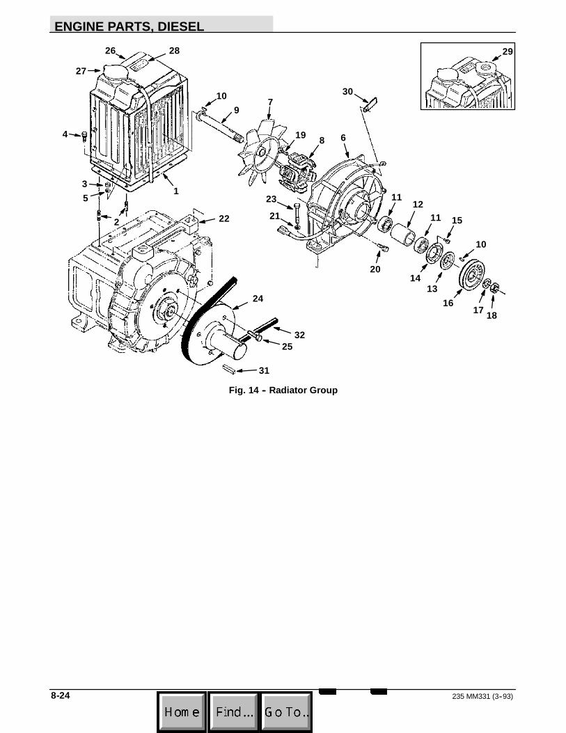
ENGINE PARTS, DIESEL
235 MM331 (3--93)8-24
1
2
3
4
5
6
7
8
910
1112
1314
15
1617 18
19
20
2122
23
24
25
26
27
28 29
30
31
32
11
10
Fig. 14 -- Radiator Group

ENGINE PARTS, DIESEL
8-25235 MM331 (8--95)
03619Fig. 14 -- Radiator Group
TENNANT Kubota EngineKey Part No. Part Number Serial Number Description Qty.
1 87946 15271--7212--0 (000000-- ) Gasket, Radiator 12 01513--50618 (000000-- ) Stud 63 39121 02056--50060 (000000-- ) Nut 64 39119 01023--50620 (000000-- ) Bolt 65 39065 04512--60060 (000000-- ) Washer, Spring 6
15908--7401--0 (000000-- ) Fan Assembly 16 15272--7412--0 (000000-- ) Cover, Fan 17 51298 15271--7411--0 (000000-- ) Fan, Cooling 18 15272--7420--0 (000000-- ) Coil 19 15271--7414--0 (000000-- ) Shaft, Cooling Fan 1
10 15271--9523--0 (000000-- ) Key, Woodruff 211 15271--7418--0 (000000-- ) Bearing, Ball 212 15271--7429--0 (000000-- ) Collar, Shaft 113 15271--7427--0 (000000-- ) Seal, Dust 114 15271--7426--0 (000000-- ) Plate, Retainer 115 15271--9301--0 (000000-- ) Screw 416 15901--7425--0 (000000-- ) Pulley, Cooling Fan 117 15271--9407--0 (000000-- ) Washer, Spring 118 15271--9202--0 (000000-- ) Nut 119 15271--9302--0 (000000-- ) Screw, with Washer 320 39128 01123--50825 (000000-- ) Bolt 221 39097 04512--60080 (000000-- ) Washer, Spring 222 15272--7421--0 (000000-- ) Bracket, Fan 123 15272--9101--0 (000000-- ) Bolt 224 19289--84511 (000000-- ) Shaft, Stub 125 01133--51032 (000000-- ) Bolt 326 87943 19217--7206--0 (000000-- ) Radiator 127 87944 15272--7202--0 (000000-- ) Cap, 0.9 128 19212--8761--0 (000000-- ) Label, Radiator 129 87945 15272--7203--0 (000000--xxxxxx ) Cap, 1.2 130 15272--6757--0 (000000-- ) Clamp, Cord 231 19142--95011 (000000-- ) Key 132 87947 15272--7253--0 (000000-- ) Belt 1

ENGINE PARTS, DIESEL
235 MM331 (3--93)8-26

CROSS REFERENCE
9-1235 MM331 (8--95)
SECTION 9CONTENTS
PagePART NUMBER TO PAGE NUMBER CROSS
REFERENCE LIST 9--3. . . . . . . . . . . . . . . . . . . . .

CROSS REFERENCE
235 MM331 (8--95)9-2
PART NUMBER TO PAGE NUMBER CROSS REFERENCE LIST
Part PageNumber Number00500--15 7-5, 7-12. . . . . . . .00500--4 5-25, 7-11. . . . . . . . .00912 7-7. . . . . . . . . . . .00928 5-27, 5-29. . . . . . . . . . . .00960 5-25. . . . . . . . . . . .01023--50616 8-11, 8-13. . . . .01023--50618 8-5, 8-8, 8-23. . . . .01023--50620 8-25. . . . .01023--50625 8-9. . . . .01053--50612 8-7, 8-15. . . . .01053--50614 8-15. . . . .01053--50618 8-7. . . . .01053--50635 8-7. . . . .01053--50655 8-5. . . . .01123--50820 8-17. . . . .01123--50825 8-21, 8-25. . . . .01123--50828 8-8. . . . .01123--50830 8-13. . . . .01123--60816 8-13. . . . .01133--51032 8-25. . . . .01153--50816 8-13. . . . .01153--50818 8-5, 8-13, 8-17, 8-20. . . . .01153--50840 8-20. . . . .01222--50610 8-23. . . . .01513--50618 8-25. . . . .01513--50620 8-8, 8-13. . . . .01513--50650 8-13. . . . .01513--50822 8-21. . . . .01518--50614 8-7, 8-11. . . . .01666 7-6. . . . . . . . . . . .01669 7-6. . . . . . . . . . . .01760 5-7. . . . . . . . . . . .01844 5-27. . . . . . . . . . . .01866 5-27. . . . . . . . . . . .02012--50060 8-23. . . . .02056--50050 8-15. . . . .02056--50060 8-7, 8-8, 8-11, 8-13, 8-25. . . . .02076 5-47. . . . . . . . . . . .02112--50080 8-23. . . . .02156--50080 8-20, 8-21. . . . .02218 5-35. . . . . . . . . . . .02247 5-49. . . . . . . . . . . .02356 5-27. . . . . . . . . . . .02545 5-38. . . . . . . . . . . .02637 5-39. . . . . . . . . . . .02643 7-4. . . . . . . . . . . .02644 7-4. . . . . . . . . . . .02646 7-4. . . . . . . . . . . .02647 7-4. . . . . . . . . . . .02965 6-13. . . . . . . . . . . .03024--50520 8-21. . . . .03410--00606 8-14. . . . .04012--50080 8-23. . . . .04512--60060 8-5, 8-7, 8-8, 8-11,. . . . .
8-13, 8-15, 8-20, 8-2504512--60080 8-5, 8-13, 8-17, 8-20,. . . . .
8-21, 8-23, 8-2504612--00110 8-14. . . . .04724--00120 8-23. . . . .
Part PageNumber Number04733--4 5-33. . . . . . . . .04733 5-31. . . . . . . . . . . .04734 5-31. . . . . . . . . . . .04810--00150 8-11. . . . .04811--00080 8-15. . . . .04811--00120 8-5. . . . .04811--10040 8-7. . . . .04811--10070 8-23. . . . .04811--10100 8-5. . . . .04811--10120 8-5. . . . .04811--50300 8-11. . . . .05012--00608 8-7. . . . .05712--00515 8-19. . . . .05712--00725 8-20. . . . .06279 5-25. . . . . . . . . . . .06311--75040 8-5. . . . .06474A 5-44, 6-13. . . . . . . . . .06678 6-13. . . . . . . . . . . .07259 5-43. . . . . . . . . . . .07715--03205 8-17. . . . .07715--03217 8-17. . . . .07875 5-49. . . . . . . . . . . .07916--2454--0 8-5. . . .07916--2455--0 8-5. . . .08143 5-25. . . . . . . . . . . .08228 5-49. . . . . . . . . . . .08232--1 5-47. . . . . . . . .08873 5-49. . . . . . . . . . . .08876 5-49. . . . . . . . . . . .08885 5-54. . . . . . . . . . . .09005 5-27, 5-29. . . . . . . . . . . .09087 5-23. . . . . . . . . . . .09370 5-27. . . . . . . . . . . .10120 5-11. . . . . . . . . . . .10127 6-7. . . . . . . . . . . .10137 5-47. . . . . . . . . . . .10362 5-25. . . . . . . . . . . .10632--11 5-18. . . . . . . .10632--12 6-6. . . . . . . .10632--13 5-13. . . . . . . .10632--15 5-18. . . . . . . .10632 6-13. . . . . . . . . . . .10895 8-7. . . . . . . . . . . .11531 5-47. . . . . . . . . . . .12788 8-19. . . . . . . . . . . .12789 8-9. . . . . . . . . . . .12790 8-19. . . . . . . . . . . .12791 8-19. . . . . . . . . . . .12792 8-19. . . . . . . . . . . .12799 8-21. . . . . . . . . . . .12891 8-21. . . . . . . . . . . .12893 8-21. . . . . . . . . . . .12894 8-21. . . . . . . . . . . .12895 8-17. . . . . . . . . . . .12896 8-15. . . . . . . . . . . .12897 8-14. . . . . . . . . . . .12898 8-14. . . . . . . . . . . .12899 8-14. . . . . . . . . . . .12912 8-13. . . . . . . . . . . .

CROSS REFERENCE
9-3235 MM331 (8--95)
Part PageNumber Number12913 8-13. . . . . . . . . . . .12914 8-13. . . . . . . . . . . .12915 8-13. . . . . . . . . . . .12916 8-11. . . . . . . . . . . .12917 8-7. . . . . . . . . . . .12918 8-7. . . . . . . . . . . .12919 8-7. . . . . . . . . . . .12920 8-7. . . . . . . . . . . .12921 8-5. . . . . . . . . . . .12922 8-5. . . . . . . . . . . .12923 8-5. . . . . . . . . . . .12924 8-5. . . . . . . . . . . .12925 8-5. . . . . . . . . . . .13352 5-11. . . . . . . . . . . .13534 5-27, 5-29. . . . . . . . . . . .13773 5-38. . . . . . . . . . . .14111--4241--0 8-21. . . .14131 5-49. . . . . . . . . . . .14138A 5-43. . . . . . . . . .14242 5-39. . . . . . . . . . . .14301--3363--0 8-5. . . .14301--5442--0 8-11. . . .14301--5443--0 8-11. . . .14301--5767--3 8-23. . . .14301--7311--0 8-8. . . .14432 5-47. . . . . . . . . . . .14506 5-44. . . . . . . . . . . .14595--1 5-11. . . . . . . . .14605 5-11, 5-37. . . . . . . . . . . .14611--9106--0 8-7. . . .14971--4275--0 8-21. . . .15021--3366--0 8-7. . . .15108--5728--0 8-23. . . .15109--3366--0 8-5. . . .15121--5385--0 8-21. . . .15121--5386--0 8-21. . . .15131--0138--0 8-19. . . .15173 6-13. . . . . . . . . . . .15221--1172--0 8-13. . . .15221--3314--0 8-11. . . .15221--3362--0 8-7. . . .15221--3363--0 8-5. . . .15221--3364--0 8-7. . . .15221--3365--0 8-5. . . .15221--3370--0 8-5. . . .15221--5211--0 8-21. . . .15221--5628--0 8-7. . . .15221--6628--0 8-15. . . .15221--6641--0 8-15. . . .15231--0511--0 8-11. . . .15231--0513--0 8-11. . . .15231--0567--0 8-11. . . .15231--3395--0 8-5. . . .15231--3396--0 8-5. . . .15231--3901--0 8-21. . . .15231--5423--0 8-11. . . .15241--1135--2 8-13. . . .15241--3209--0 8-11. . . .15241--3229--0 8-11. . . .15261--0337--0 8-8. . . .15261--0454--0 8-9. . . .15261--0456--0 8-9. . . .
Part PageNumber Number15261--0457--0 8-9. . . .15261--0459--0 8-9. . . .15261--1172--0 8-13. . . .15261--1182--0 8-13. . . .15261--1183--0 8-13. . . .15261--1315--0 8-14. . . .15261--1324--0 8-14. . . .15261--1328--0 8-14. . . .15261--1333--0 8-14. . . .15261--1336--0 8-14. . . .15261--1354--0 8-8. . . .15261--1356--0 8-8. . . .15261--1403--0 8-14. . . .15261--1418--0 8-14. . . .15261--1423--0 8-14. . . .15261--1424--0 8-14. . . .15261--1431--0 8-14. . . .15261--1435--0 8-14. . . .15261--1441--0 8-14. . . .15261--1442--0 8-14. . . .15261--1443--0 8-14. . . .15261--1452--0 8-15. . . .15261--1462--0 8-15. . . .15261--1463--0 8-15. . . .15261--1464--0 8-15. . . .15261--1555--0 8-17. . . .15261--2131--0 8-19. . . .15261--2133--0 8-19. . . .15261--2135--0 8-19. . . .15261--2198--0 8-19. . . .15261--2214--0 8-19. . . .15261--2297--0 8-19. . . .15261--2298--0 8-19. . . .15261--2336--0 8-19. . . .15261--2338--2 8-19. . . .15261--2347--0 8-19. . . .15261--2353--0 8-19. . . .15261--2354--0 8-19. . . .15261--2391--0 8-19. . . .15261--2392--0 8-19. . . .15261--2395--0 8-19. . . .15261--2396--0 8-19. . . .15261--2397--0 8-19. . . .15261--2398--0 8-19. . . .15261--2428--0 8-17. . . .15261--2432--0 8-17. . . .15261--2436--0 8-17. . . .15261--2437--0 8-17. . . .15261--2498--0 8-17. . . .15261--3375--0 8-5. . . .15261--3607--0 8-11. . . .15261--5422--0 8-11. . . .15261--5437--0 8-11. . . .15261--5545--0 8-17. . . .15261--5547--0 8-17. . . .15261--5569--0 8-17. . . .15261--5574--0 8-17. . . .15261--6551--0 8-21. . . .15261--6556--0 8-21. . . .15261--6619--0 8-15. . . .15261--6635--0 8-15. . . .15261--6663--0 8-15. . . .
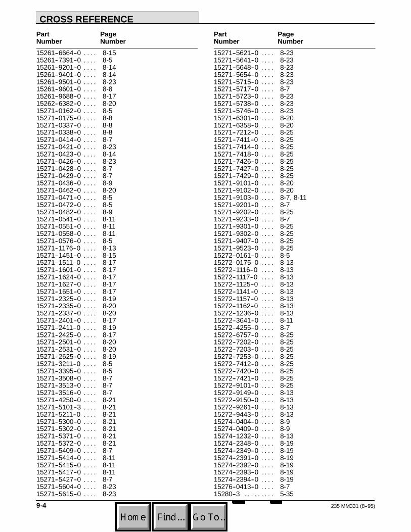
CROSS REFERENCE
235 MM331 (8--95)9-4
Part PageNumber Number15261--6664--0 8-15. . . .15261--7391--0 8-5. . . .15261--9201--0 8-14. . . .15261--9401--0 8-14. . . .15261--9501--0 8-23. . . .15261--9601--0 8-8. . . .15261--9688--0 8-17. . . .15262--6382--0 8-20. . . .15271--0162--0 8-5. . . .15271--0175--0 8-8. . . .15271--0337--0 8-8. . . .15271--0338--0 8-8. . . .15271--0414--0 8-7. . . .15271--0421--0 8-23. . . .15271--0423--0 8-14. . . .15271--0426--0 8-23. . . .15271--0428--0 8-7. . . .15271--0429--0 8-7. . . .15271--0436--0 8-9. . . .15271--0462--0 8-20. . . .15271--0471--0 8-5. . . .15271--0472--0 8-5. . . .15271--0482--0 8-9. . . .15271--0541--0 8-11. . . .15271--0551--0 8-11. . . .15271--0558--0 8-11. . . .15271--0576--0 8-5. . . .15271--1176--0 8-13. . . .15271--1451--0 8-15. . . .15271--1511--0 8-17. . . .15271--1601--0 8-17. . . .15271--1624--0 8-17. . . .15271--1627--0 8-17. . . .15271--1651--0 8-17. . . .15271--2325--0 8-19. . . .15271--2335--0 8-20. . . .15271--2337--0 8-20. . . .15271--2401--0 8-17. . . .15271--2411--0 8-19. . . .15271--2425--0 8-17. . . .15271--2501--0 8-20. . . .15271--2531--0 8-20. . . .15271--2625--0 8-19. . . .15271--3211--0 8-5. . . .15271--3395--0 8-5. . . .15271--3508--0 8-7. . . .15271--3513--0 8-7. . . .15271--3516--0 8-7. . . .15271--4250--0 8-21. . . .15271--5101--3 8-21. . . .15271--5211--0 8-21. . . .15271--5300--0 8-21. . . .15271--5302--0 8-21. . . .15271--5371--0 8-21. . . .15271--5372--0 8-21. . . .15271--5409--0 8-7. . . .15271--5414--0 8-11. . . .15271--5415--0 8-11. . . .15271--5417--0 8-11. . . .15271--5427--0 8-7. . . .15271--5604--0 8-23. . . .15271--5615--0 8-23. . . .
Part PageNumber Number15271--5621--0 8-23. . . .15271--5641--0 8-23. . . .15271--5648--0 8-23. . . .15271--5654--0 8-23. . . .15271--5715--0 8-23. . . .15271--5717--0 8-7. . . .15271--5723--0 8-23. . . .15271--5738--0 8-23. . . .15271--5746--0 8-23. . . .15271--6301--0 8-20. . . .15271--6358--0 8-20. . . .15271--7212--0 8-25. . . .15271--7411--0 8-25. . . .15271--7414--0 8-25. . . .15271--7418--0 8-25. . . .15271--7426--0 8-25. . . .15271--7427--0 8-25. . . .15271--7429--0 8-25. . . .15271--9101--0 8-20. . . .15271--9102--0 8-20. . . .15271--9103--0 8-7, 8-11. . . .15271--9201--0 8-7. . . .15271--9202--0 8-25. . . .15271--9233--0 8-7. . . .15271--9301--0 8-25. . . .15271--9302--0 8-25. . . .15271--9407--0 8-25. . . .15271--9523--0 8-25. . . .15272--0161--0 8-5. . . .15272--0175--0 8-13. . . .15272--1116--0 8-13. . . .15272--1117--0 8-13. . . .15272--1125--0 8-13. . . .15272--1141--0 8-13. . . .15272--1157--0 8-13. . . .15272--1162--0 8-13. . . .15272--1236--0 8-13. . . .15272--3641--0 8-11. . . .15272--4255--0 8-7. . . .15272--6757--0 8-25. . . .15272--7202--0 8-25. . . .15272--7203--0 8-25. . . .15272--7253--0 8-25. . . .15272--7412--0 8-25. . . .15272--7420--0 8-25. . . .15272--7421--0 8-25. . . .15272--9101--0 8-25. . . .15272--9149--0 8-13. . . .15272--9150--0 8-13. . . .15272--9261--0 8-13. . . .15272--9443--0 8-13. . . .15274--0404--0 8-9. . . .15274--0409--0 8-9. . . .15274--1232--0 8-13. . . .15274--2348--0 8-19. . . .15274--2349--0 8-19. . . .15274--2391--0 8-19. . . .15274--2392--0 8-19. . . .15274--2393--0 8-19. . . .15274--2394--0 8-19. . . .15276--0413--0 8-7. . . .15280--3 5-35. . . . . . . . .

CROSS REFERENCE
9-5235 MM331 (8--95)
Part PageNumber Number15321--9626--0 8-5, 8-8. . . .15393--1311--0 8-14. . . .15393--1312--0 8-14. . . .15531--2201--0 8-19. . . .15531--2231--0 8-19. . . .15543 5-47. . . . . . . . . . . .15901--0231--0 8-5. . . .15901--0304--0 8-8. . . .15901--0331--4 8-8. . . .15901--0332--0 8-8. . . .15901--0402--0 8-7. . . .15901--0427--0 8-11. . . .15901--1405--0 8-14. . . .15901--2105--0 8-19. . . .15901--2109--0 8-19. . . .15901--2111--0 8-19. . . .15901--2191--0 8-19. . . .15901--3363--0 8-5. . . .15901--5402--0 8-11. . . .15901--5419--0 8-11. . . .15901--5657--0 8-23. . . .15901--7425--0 8-25. . . .15903--0101--0 8-5. . . .15908--7401--0 8-25. . . .15951--6604--0 8-15. . . .16447 5-29, 5-31. . . . . . . . . . . .16455 5-33. . . . . . . . . . . .16695 7-5. . . . . . . . . . . .16931 5-47. . . . . . . . . . . .16934 5-25. . . . . . . . . . . .17414 5-49. . . . . . . . . . . .19142--95011 8-25. . . . .19212--8759--0 8-7. . . .19212--8761--0 8-25. . . .19212--8821--0 8-7. . . .19212--8822--0 8-11. . . .19212--8823--0 8-15. . . .19212--8824--0 8-13. . . .19215--0341--2 8-8. . . .19215--0345--0 8-8. . . .19215--0351--2 8-8. . . .19215--0446--0 8-9. . . .19215--0481--0 8-9. . . .19215--1101--2 8-13. . . .19215--1122--0 8-13. . . .19215--2301--0 8-19. . . .19215--2328--0 8-19. . . .19215--8745--0 8-13. . . .19215--9905--0 8-5. . . .19217--7206--0 8-25. . . .19231--8731--0 8-7. . . .19234--8721--0 8-11. . . .19289--84511 8-25. . . . .19634 6-14. . . . . . . . . . . .20634 5-19. . . . . . . . . . . .22297 5-47. . . . . . . . . . . .23224 5-27. . . . . . . . . . . .23225 5-27. . . . . . . . . . . .23498 5-23. . . . . . . . . . . .23524--1 5-21. . . . . . . . .23524 5-21. . . . . . . . . . . .23683 6-13. . . . . . . . . . . .
Part PageNumber Number24012 5-47. . . . . . . . . . . .24339 5-39. . . . . . . . . . . .24976 5-49. . . . . . . . . . . .25121 5-38. . . . . . . . . . . .25494 5-25. . . . . . . . . . . .26103 5-35. . . . . . . . . . . .26315 5-11. . . . . . . . . . . .26395--2 5-18, 6-7. . . . . . . . .27184 6-13. . . . . . . . . . . .27920 6-11. . . . . . . . . . . .28804 5-31, 6-13, 7-12. . . . . . . . . . . .28835 7-12. . . . . . . . . . . .28862 5-11. . . . . . . . . . . .29233 5-9. . . . . . . . . . . .29584 5-45. . . . . . . . . . . .30045 8-13. . . . . . . . . . . .30056 8-20. . . . . . . . . . . .30057 8-19. . . . . . . . . . . .30106 8-5. . . . . . . . . . . .30107 8-5. . . . . . . . . . . .30205 5-27. . . . . . . . . . . .31182 6-13. . . . . . . . . . . .31258 5-47. . . . . . . . . . . .31354 7-12. . . . . . . . . . . .31559 5-38. . . . . . . . . . . .32126 5-39. . . . . . . . . . . .32183 5-49. . . . . . . . . . . .32969 5-33. . . . . . . . . . . .33123 5-27. . . . . . . . . . . .33296 7-7. . . . . . . . . . . .33298 7-7. . . . . . . . . . . .33299 7-7. . . . . . . . . . . .33303 7-7. . . . . . . . . . . .33304 7-7. . . . . . . . . . . .33305 7-7. . . . . . . . . . . .33671 5-47. . . . . . . . . . . .34150--1397--0 8-13. . . .34174 7-5. . . . . . . . . . . .34176 7-5, 7-12. . . . . . . . . . . .34219 6-13. . . . . . . . . . . .34292 5-4, 5-7. . . . . . . . . . . .34323 5-4, 5-15. . . . . . . . . . . .34358 5-41. . . . . . . . . . . .34413 6-13. . . . . . . . . . . .34414 6-13. . . . . . . . . . . .34810 5-51. . . . . . . . . . . .34813 5-51. . . . . . . . . . . .35273 6-13. . . . . . . . . . . .35274 6-13. . . . . . . . . . . .35278 6-13. . . . . . . . . . . .35279 6-13. . . . . . . . . . . .35280 6-13. . . . . . . . . . . .35304 6-11. . . . . . . . . . . .36070 5-31. . . . . . . . . . . .36192 5-9. . . . . . . . . . . .36328 6-5. . . . . . . . . . . .36468 5-31. . . . . . . . . . . .38315 7-4. . . . . . . . . . . .38490 7-4. . . . . . . . . . . .39060 8-5. . . . . . . . . . . .39063 8-5. . . . . . . . . . . .

CROSS REFERENCE
235 MM331 (8--95)9-6
Part PageNumber Number39065 8-5, 8-7, 8-8, 8-11,. . . . . . . . . . . .
8-13, 8-15, 8-20, 8-2539088 8-8. . . . . . . . . . . .39094 8-13. . . . . . . . . . . .39096 8-20, 8-21. . . . . . . . . . . .39097 8-5, 8-13, 8-17, 8-20,. . . . . . . . . . . .
8-21, 8-23, 8-2539105 8-7. . . . . . . . . . . .39119 8-25. . . . . . . . . . . .39121 8-7, 8-8, 8-11, 8-13, 8-25. . . . . . . . . . . .39128 8-21, 8-25. . . . . . . . . . . .39148 8-23. . . . . . . . . . . .39160 8-15. . . . . . . . . . . .39161 8-11. . . . . . . . . . . .39162 8-11. . . . . . . . . . . .39164 8-15. . . . . . . . . . . .39169 8-15. . . . . . . . . . . .39179 8-7. . . . . . . . . . . .39183 8-5. . . . . . . . . . . .39210 5-31. . . . . . . . . . . .39296 5-11. . . . . . . . . . . .39328 5-25. . . . . . . . . . . .39330 5-35. . . . . . . . . . . .39332 5-35. . . . . . . . . . . .39345 5-47. . . . . . . . . . . .39350 5-27, 5-29. . . . . . . . . . . .39506 8-21. . . . . . . . . . . .39507 8-21. . . . . . . . . . . .39508 8-21. . . . . . . . . . . .39512 8-21. . . . . . . . . . . .39523 8-17. . . . . . . . . . . .39527 5-27, 5-29. . . . . . . . . . . .39784 8-21. . . . . . . . . . . .40204 8-5. . . . . . . . . . . .40233 8-23. . . . . . . . . . . .40290 8-23. . . . . . . . . . . .40362 5-38. . . . . . . . . . . .40405 8-23. . . . . . . . . . . .40409 8-5, 8-8, 8-23. . . . . . . . . . . .40678--1 5-47, 5-51. . . . . . . . .40678 5-19. . . . . . . . . . . .41178 5-31, 6-13. . . . . . . . . . . .41185 5-31, 6-13. . . . . . . . . . . .41187 5-13. . . . . . . . . . . .41973 8-11, 8-13. . . . . . . . . . . .42215 5-35. . . . . . . . . . . .42240 5-44. . . . . . . . . . . .43242 5-37. . . . . . . . . . . .43454 5-9, 5-37. . . . . . . . . . . .43499 6-13. . . . . . . . . . . .43560 6-13. . . . . . . . . . . .43844 5-47, 5-49. . . . . . . . . . . .44078 5-23, 5-43. . . . . . . . . . . .44681--1 6-6, 6-7. . . . . . . . .44681--2 6-6, 6-7. . . . . . . . .44681 6-6, 6-7. . . . . . . . . . . .45079 6-8. . . . . . . . . . . .45097 6-13. . . . . . . . . . . .45127 5-45. . . . . . . . . . . .45261 5-31. . . . . . . . . . . .45628 7-5. . . . . . . . . . . .45779 6-6, 6-7. . . . . . . . . . . .
Part PageNumber Number46140 5-23. . . . . . . . . . . .46236 5-9. . . . . . . . . . . .46390 5-11. . . . . . . . . . . .46482 5-33. . . . . . . . . . . .46785--1 5-27. . . . . . . . .47069 5-5, 5-23. . . . . . . . . . . .47277 5-7. . . . . . . . . . . .47508 5-35, 5-38. . . . . . . . . . . .47513 5-35. . . . . . . . . . . .47519 5-33. . . . . . . . . . . .47638 5-33, 5-35. . . . . . . . . . . .47649 7-5. . . . . . . . . . . .47719 5-39. . . . . . . . . . . .47801 5-39. . . . . . . . . . . .48050 5-43. . . . . . . . . . . .48144 5-49. . . . . . . . . . . .48556 6-13. . . . . . . . . . . .48557 6-13. . . . . . . . . . . .48563 6-13. . . . . . . . . . . .48567 6-13. . . . . . . . . . . .48568 5-51. . . . . . . . . . . .48570 5-51. . . . . . . . . . . .48571 6-10. . . . . . . . . . . .48572 6-10. . . . . . . . . . . .48575 5-33, 7-9. . . . . . . . . . . .48577 7-9, 7-10. . . . . . . . . . . .48580 6-13. . . . . . . . . . . .48581 6-13. . . . . . . . . . . .48582 6-13. . . . . . . . . . . .48584 6-13. . . . . . . . . . . .48587 6-13. . . . . . . . . . . .48617 6-14. . . . . . . . . . . .48654 5-47. . . . . . . . . . . .48656 5-47. . . . . . . . . . . .48657 5-33. . . . . . . . . . . .48658 5-47. . . . . . . . . . . .48685 6-9. . . . . . . . . . . .48790 5-9. . . . . . . . . . . .49225 5-39. . . . . . . . . . . .49263 5-47. . . . . . . . . . . .49266 5-9, 5-31, 6-6, 6-7, 6-13. . . . . . . . . . . .49287 6-13. . . . . . . . . . . .49300 5-23. . . . . . . . . . . .49439 5-27. . . . . . . . . . . .49452 5-43. . . . . . . . . . . .49495 5-27. . . . . . . . . . . .50186 7-12. . . . . . . . . . . .50970 8-17. . . . . . . . . . . .50992 8-21. . . . . . . . . . . .50995 8-9. . . . . . . . . . . .50996 8-9. . . . . . . . . . . .50997 8-14. . . . . . . . . . . .50998 8-8. . . . . . . . . . . .50999 8-8. . . . . . . . . . . .51011 8-19. . . . . . . . . . . .51014 8-19. . . . . . . . . . . .51019 8-19. . . . . . . . . . . .51020 8-19. . . . . . . . . . . .51109 5-11. . . . . . . . . . . .51194 8-19. . . . . . . . . . . .51275 8-19. . . . . . . . . . . .51276 8-19. . . . . . . . . . . .

CROSS REFERENCE
9-7235 MM331 (8--95)
Part PageNumber Number51277 8-19. . . . . . . . . . . .51282 8-17. . . . . . . . . . . .51284 8-11. . . . . . . . . . . .51286 8-8. . . . . . . . . . . .51288 8-21. . . . . . . . . . . .51292 8-21. . . . . . . . . . . .51293 8-7. . . . . . . . . . . .51295 8-13. . . . . . . . . . . .51296 8-19. . . . . . . . . . . .51297 8-19. . . . . . . . . . . .51298 8-25. . . . . . . . . . . .51322 5-19. . . . . . . . . . . .51331 8-5, 8-8. . . . . . . . . . . .51336 8-19. . . . . . . . . . . .51342 8-5. . . . . . . . . . . .51343 8-8. . . . . . . . . . . .51345 8-8. . . . . . . . . . . .51348 8-19. . . . . . . . . . . .51351 8-19. . . . . . . . . . . .51352 8-19. . . . . . . . . . . .51353 8-19. . . . . . . . . . . .51387 8-19. . . . . . . . . . . .51449 5-43. . . . . . . . . . . .51458 6-9. . . . . . . . . . . .51459 6-9. . . . . . . . . . . .51534 6-13. . . . . . . . . . . .51545 5-11. . . . . . . . . . . .51562 5-11. . . . . . . . . . . .51706--1 5-47. . . . . . . . .51787 5-33. . . . . . . . . . . .52238 5-13. . . . . . . . . . . .52615 6-9. . . . . . . . . . . .53029 5-49. . . . . . . . . . . .54121 5-19. . . . . . . . . . . .54205--4117--0 8-20. . . .54266--8174--0 8-13. . . .54526--2 5-47. . . . . . . . .54914 5-47. . . . . . . . . . . .55248 6-7. . . . . . . . . . . .55264 6-6, 6-7. . . . . . . . . . . .55271 5-51. . . . . . . . . . . .55272 5-51. . . . . . . . . . . .55347 5-29. . . . . . . . . . . .55686 5-33, 5-37. . . . . . . . . . . .56692 5-35, 5-39. . . . . . . . . . . .56835 5-35. . . . . . . . . . . .57164 5-51. . . . . . . . . . . .57219 5-41. . . . . . . . . . . .57370 7-4. . . . . . . . . . . .57373 7-4. . . . . . . . . . . .57374 7-4. . . . . . . . . . . .57375 7-4. . . . . . . . . . . .57452 5-31. . . . . . . . . . . .57497 5-43. . . . . . . . . . . .57751 5-51, 6-11. . . . . . . . . . . .57772 5-9. . . . . . . . . . . .57792 5-49. . . . . . . . . . . .57803 5-51. . . . . . . . . . . .57807 5-51, 6-11. . . . . . . . . . . .57947 6-14. . . . . . . . . . . .57965 5-41. . . . . . . . . . . .57967 6-14. . . . . . . . . . . .
Part PageNumber Number57984 5-31, 5-35, 5-37, 6-13. . . . . . . . . . . .58346 5-47. . . . . . . . . . . .58494 6-13. . . . . . . . . . . .58536 5-47. . . . . . . . . . . .58670 5-31. . . . . . . . . . . .58842 5-39. . . . . . . . . . . .59118--7 5-47. . . . . . . . .60453 6-10, 8-21. . . . . . . . . . . .61288 5-38. . . . . . . . . . . .61406 5-53. . . . . . . . . . . .61961 5-49. . . . . . . . . . . .62170--2 5-9. . . . . . . . .62595--18 5-51. . . . . . . .62595--21 6-5. . . . . . . .63147 5-21. . . . . . . . . . . .64141 5-51. . . . . . . . . . . .64379 5-21. . . . . . . . . . . .64595 6-13. . . . . . . . . . . .65223 5-33, 7-10. . . . . . . . . . . .65556 5-51. . . . . . . . . . . .65560 6-11. . . . . . . . . . . .65561 5-51. . . . . . . . . . . .65577 5-21. . . . . . . . . . . .65870--5 5-4. . . . . . . . .66099 6-9. . . . . . . . . . . .67718--2 5-4, 5-33. . . . . . . . .67718 5-33. . . . . . . . . . . .68106 5-47. . . . . . . . . . . .68198 5-4, 5-5. . . . . . . . . . . .68275 5-9. . . . . . . . . . . .68872 5-47. . . . . . . . . . . .68873 5-47. . . . . . . . . . . .69158 5-35. . . . . . . . . . . .69159 5-35. . . . . . . . . . . .69736 5-49. . . . . . . . . . . .70000--65259 8-21. . . . .70000 5-53. . . . . . . . . . . .70006 5-38. . . . . . . . . . . .70957 8-20. . . . . . . . . . . .75400 5-49. . . . . . . . . . . .77098 5-39. . . . . . . . . . . .82229 6-13. . . . . . . . . . . .82239 5-39. . . . . . . . . . . .82342 5-9. . . . . . . . . . . .82509 5-4, 5-49. . . . . . . . . . . .82544 5-49. . . . . . . . . . . .82621 6-13. . . . . . . . . . . .82682 5-49. . . . . . . . . . . .82692 5-4, 5-49. . . . . . . . . . . .82709 5-47. . . . . . . . . . . .82784 5-38. . . . . . . . . . . .82802 5-33. . . . . . . . . . . .82809 5-41. . . . . . . . . . . .82816 5-41. . . . . . . . . . . .82839 5-44. . . . . . . . . . . .82842 5-27. . . . . . . . . . . .86646 5-13, 5-35. . . . . . . . . . . .86922 5-11. . . . . . . . . . . .87022 5-51. . . . . . . . . . . .87027 5-27. . . . . . . . . . . .87030 5-27, 5-29. . . . . . . . . . . .87040 5-27. . . . . . . . . . . .
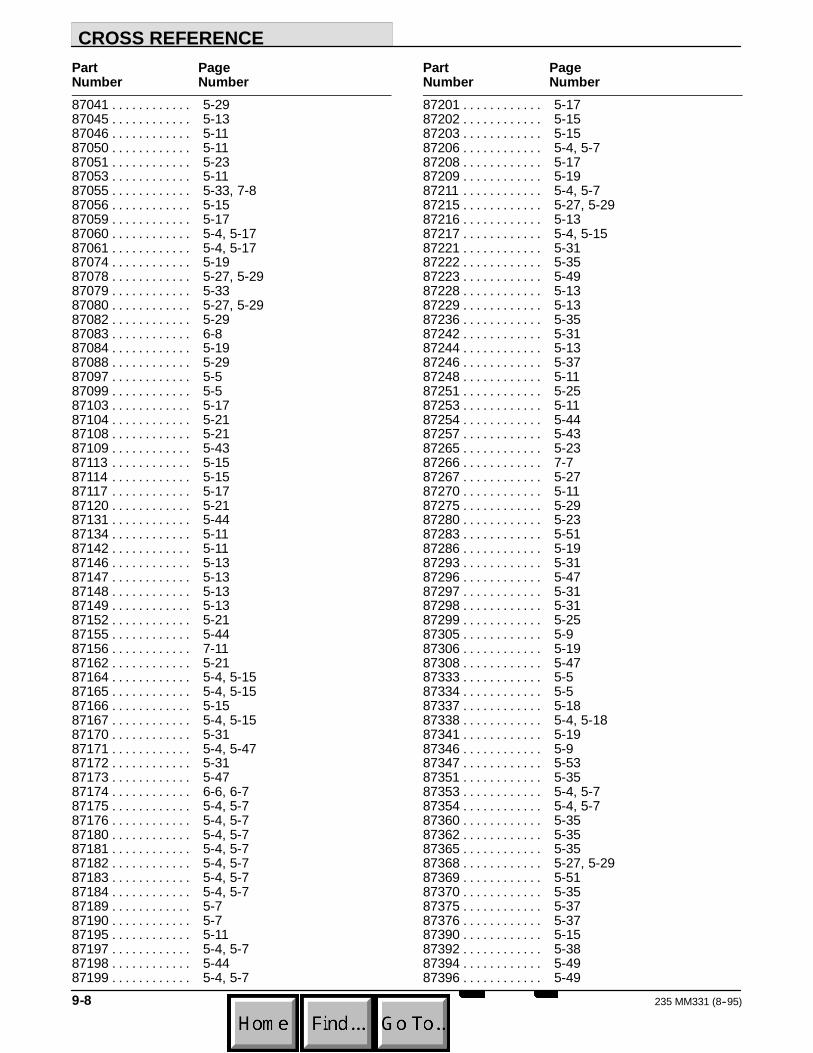
CROSS REFERENCE
235 MM331 (8--95)9-8
Part PageNumber Number87041 5-29. . . . . . . . . . . .87045 5-13. . . . . . . . . . . .87046 5-11. . . . . . . . . . . .87050 5-11. . . . . . . . . . . .87051 5-23. . . . . . . . . . . .87053 5-11. . . . . . . . . . . .87055 5-33, 7-8. . . . . . . . . . . .87056 5-15. . . . . . . . . . . .87059 5-17. . . . . . . . . . . .87060 5-4, 5-17. . . . . . . . . . . .87061 5-4, 5-17. . . . . . . . . . . .87074 5-19. . . . . . . . . . . .87078 5-27, 5-29. . . . . . . . . . . .87079 5-33. . . . . . . . . . . .87080 5-27, 5-29. . . . . . . . . . . .87082 5-29. . . . . . . . . . . .87083 6-8. . . . . . . . . . . .87084 5-19. . . . . . . . . . . .87088 5-29. . . . . . . . . . . .87097 5-5. . . . . . . . . . . .87099 5-5. . . . . . . . . . . .87103 5-17. . . . . . . . . . . .87104 5-21. . . . . . . . . . . .87108 5-21. . . . . . . . . . . .87109 5-43. . . . . . . . . . . .87113 5-15. . . . . . . . . . . .87114 5-15. . . . . . . . . . . .87117 5-17. . . . . . . . . . . .87120 5-21. . . . . . . . . . . .87131 5-44. . . . . . . . . . . .87134 5-11. . . . . . . . . . . .87142 5-11. . . . . . . . . . . .87146 5-13. . . . . . . . . . . .87147 5-13. . . . . . . . . . . .87148 5-13. . . . . . . . . . . .87149 5-13. . . . . . . . . . . .87152 5-21. . . . . . . . . . . .87155 5-44. . . . . . . . . . . .87156 7-11. . . . . . . . . . . .87162 5-21. . . . . . . . . . . .87164 5-4, 5-15. . . . . . . . . . . .87165 5-4, 5-15. . . . . . . . . . . .87166 5-15. . . . . . . . . . . .87167 5-4, 5-15. . . . . . . . . . . .87170 5-31. . . . . . . . . . . .87171 5-4, 5-47. . . . . . . . . . . .87172 5-31. . . . . . . . . . . .87173 5-47. . . . . . . . . . . .87174 6-6, 6-7. . . . . . . . . . . .87175 5-4, 5-7. . . . . . . . . . . .87176 5-4, 5-7. . . . . . . . . . . .87180 5-4, 5-7. . . . . . . . . . . .87181 5-4, 5-7. . . . . . . . . . . .87182 5-4, 5-7. . . . . . . . . . . .87183 5-4, 5-7. . . . . . . . . . . .87184 5-4, 5-7. . . . . . . . . . . .87189 5-7. . . . . . . . . . . .87190 5-7. . . . . . . . . . . .87195 5-11. . . . . . . . . . . .87197 5-4, 5-7. . . . . . . . . . . .87198 5-44. . . . . . . . . . . .87199 5-4, 5-7. . . . . . . . . . . .
Part PageNumber Number87201 5-17. . . . . . . . . . . .87202 5-15. . . . . . . . . . . .87203 5-15. . . . . . . . . . . .87206 5-4, 5-7. . . . . . . . . . . .87208 5-17. . . . . . . . . . . .87209 5-19. . . . . . . . . . . .87211 5-4, 5-7. . . . . . . . . . . .87215 5-27, 5-29. . . . . . . . . . . .87216 5-13. . . . . . . . . . . .87217 5-4, 5-15. . . . . . . . . . . .87221 5-31. . . . . . . . . . . .87222 5-35. . . . . . . . . . . .87223 5-49. . . . . . . . . . . .87228 5-13. . . . . . . . . . . .87229 5-13. . . . . . . . . . . .87236 5-35. . . . . . . . . . . .87242 5-31. . . . . . . . . . . .87244 5-13. . . . . . . . . . . .87246 5-37. . . . . . . . . . . .87248 5-11. . . . . . . . . . . .87251 5-25. . . . . . . . . . . .87253 5-11. . . . . . . . . . . .87254 5-44. . . . . . . . . . . .87257 5-43. . . . . . . . . . . .87265 5-23. . . . . . . . . . . .87266 7-7. . . . . . . . . . . .87267 5-27. . . . . . . . . . . .87270 5-11. . . . . . . . . . . .87275 5-29. . . . . . . . . . . .87280 5-23. . . . . . . . . . . .87283 5-51. . . . . . . . . . . .87286 5-19. . . . . . . . . . . .87293 5-31. . . . . . . . . . . .87296 5-47. . . . . . . . . . . .87297 5-31. . . . . . . . . . . .87298 5-31. . . . . . . . . . . .87299 5-25. . . . . . . . . . . .87305 5-9. . . . . . . . . . . .87306 5-19. . . . . . . . . . . .87308 5-47. . . . . . . . . . . .87333 5-5. . . . . . . . . . . .87334 5-5. . . . . . . . . . . .87337 5-18. . . . . . . . . . . .87338 5-4, 5-18. . . . . . . . . . . .87341 5-19. . . . . . . . . . . .87346 5-9. . . . . . . . . . . .87347 5-53. . . . . . . . . . . .87351 5-35. . . . . . . . . . . .87353 5-4, 5-7. . . . . . . . . . . .87354 5-4, 5-7. . . . . . . . . . . .87360 5-35. . . . . . . . . . . .87362 5-35. . . . . . . . . . . .87365 5-35. . . . . . . . . . . .87368 5-27, 5-29. . . . . . . . . . . .87369 5-51. . . . . . . . . . . .87370 5-35. . . . . . . . . . . .87375 5-37. . . . . . . . . . . .87376 5-37. . . . . . . . . . . .87390 5-15. . . . . . . . . . . .87392 5-38. . . . . . . . . . . .87394 5-49. . . . . . . . . . . .87396 5-49. . . . . . . . . . . .
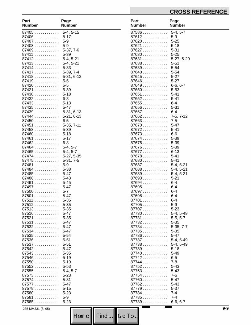
CROSS REFERENCE
9-9235 MM331 (8--95)
Part PageNumber Number87405 5-4, 5-15. . . . . . . . . . . .87406 5-17. . . . . . . . . . . .87407 5-9. . . . . . . . . . . .87408 5-9. . . . . . . . . . . .87409 5-37, 7-6. . . . . . . . . . . .87411 5-39. . . . . . . . . . . .87412 5-4, 5-21. . . . . . . . . . . .87413 5-4, 5-21. . . . . . . . . . . .87414 5-33. . . . . . . . . . . .87417 5-39, 7-4. . . . . . . . . . . .87418 5-31, 6-13. . . . . . . . . . . .87419 5-5. . . . . . . . . . . .87420 5-5. . . . . . . . . . . .87421 5-39. . . . . . . . . . . .87430 5-18. . . . . . . . . . . .87432 6-8. . . . . . . . . . . .87433 5-13. . . . . . . . . . . .87435 5-47. . . . . . . . . . . .87439 5-31, 6-13. . . . . . . . . . . .87444 5-21, 6-13. . . . . . . . . . . .87450 6-5. . . . . . . . . . . .87451 5-35, 7-11. . . . . . . . . . . .87458 5-39. . . . . . . . . . . .87460 5-18. . . . . . . . . . . .87461 5-17. . . . . . . . . . . .87462 6-8. . . . . . . . . . . .87464 5-4, 5-7. . . . . . . . . . . .87465 5-4, 5-7. . . . . . . . . . . .87474 5-27, 5-35. . . . . . . . . . . .87475 5-31, 7-5. . . . . . . . . . . .87481 5-9. . . . . . . . . . . .87484 5-38. . . . . . . . . . . .87485 5-47. . . . . . . . . . . .87488 5-43. . . . . . . . . . . .87491 5-45. . . . . . . . . . . .87497 5-47. . . . . . . . . . . .87500 5-7. . . . . . . . . . . .87501 5-47. . . . . . . . . . . .87511 5-35. . . . . . . . . . . .87512 5-35. . . . . . . . . . . .87513 5-35. . . . . . . . . . . .87516 5-47. . . . . . . . . . . .87521 5-35. . . . . . . . . . . .87531 5-47. . . . . . . . . . . .87532 5-47. . . . . . . . . . . .87534 5-47. . . . . . . . . . . .87535 5-54. . . . . . . . . . . .87536 5-51. . . . . . . . . . . .87537 5-51. . . . . . . . . . . .87542 5-47. . . . . . . . . . . .87543 5-35. . . . . . . . . . . .87546 5-19. . . . . . . . . . . .87550 5-19. . . . . . . . . . . .87552 5-53. . . . . . . . . . . .87555 5-4, 5-7. . . . . . . . . . . .87573 5-23. . . . . . . . . . . .87574 5-31. . . . . . . . . . . .87577 5-47. . . . . . . . . . . .87579 5-15. . . . . . . . . . . .87580 5-23. . . . . . . . . . . .87581 5-9. . . . . . . . . . . .87585 5-23. . . . . . . . . . . .
Part PageNumber Number87586 5-4, 5-7. . . . . . . . . . . .87612 5-9. . . . . . . . . . . .87620 5-25. . . . . . . . . . . .87621 5-18. . . . . . . . . . . .87627 5-31. . . . . . . . . . . .87630 5-25. . . . . . . . . . . .87631 5-27, 5-29. . . . . . . . . . . .87638 5-51. . . . . . . . . . . .87639 5-54. . . . . . . . . . . .87640 5-54. . . . . . . . . . . .87645 5-27. . . . . . . . . . . .87646 5-27. . . . . . . . . . . .87649 6-6, 6-7. . . . . . . . . . . .87650 5-53. . . . . . . . . . . .87651 5-41. . . . . . . . . . . .87652 5-41. . . . . . . . . . . .87655 6-4. . . . . . . . . . . .87656 5-31. . . . . . . . . . . .87657 6-4. . . . . . . . . . . .87662 7-5, 7-12. . . . . . . . . . . .87663 7-5. . . . . . . . . . . .87670 5-47. . . . . . . . . . . .87672 5-41. . . . . . . . . . . .87673 6-6. . . . . . . . . . . .87674 5-39. . . . . . . . . . . .87675 5-39. . . . . . . . . . . .87676 5-39. . . . . . . . . . . .87677 6-13. . . . . . . . . . . .87678 5-41. . . . . . . . . . . .87680 5-41. . . . . . . . . . . .87687 5-4, 5-21. . . . . . . . . . . .87688 5-4, 5-21. . . . . . . . . . . .87689 5-4, 5-21. . . . . . . . . . . .87693 5-21. . . . . . . . . . . .87694 6-4. . . . . . . . . . . .87695 6-4. . . . . . . . . . . .87697 6-4. . . . . . . . . . . .87698 6-4. . . . . . . . . . . .87701 6-4. . . . . . . . . . . .87705 5-9. . . . . . . . . . . .87707 5-23. . . . . . . . . . . .87730 5-4, 5-49. . . . . . . . . . . .87731 5-5, 5-7. . . . . . . . . . . .87732 5-35. . . . . . . . . . . .87734 5-35, 7-7. . . . . . . . . . . .87735 5-35. . . . . . . . . . . .87736 5-47. . . . . . . . . . . .87737 5-4, 5-49. . . . . . . . . . . .87738 5-4, 5-49. . . . . . . . . . . .87739 5-18. . . . . . . . . . . .87740 5-49. . . . . . . . . . . .87742 6-5. . . . . . . . . . . .87744 7-8. . . . . . . . . . . .87752 5-43. . . . . . . . . . . .87753 5-43. . . . . . . . . . . .87754 7-6. . . . . . . . . . . .87760 5-47. . . . . . . . . . . .87762 5-43. . . . . . . . . . . .87779 5-37. . . . . . . . . . . .87784 7-4. . . . . . . . . . . .87785 7-4. . . . . . . . . . . .87789 6-6, 6-7. . . . . . . . . . . .

CROSS REFERENCE
235 MM331 (8--95)9-10
Part PageNumber Number87790 6-8. . . . . . . . . . . .87791 6-7. . . . . . . . . . . .87792 6-6. . . . . . . . . . . .87797 5-45. . . . . . . . . . . .87798 5-45. . . . . . . . . . . .87803 5-45. . . . . . . . . . . .87804 5-45. . . . . . . . . . . .87807 5-47. . . . . . . . . . . .87810 5-37. . . . . . . . . . . .87811 5-37. . . . . . . . . . . .87813 5-47. . . . . . . . . . . .87816 5-37. . . . . . . . . . . .87818 5-37. . . . . . . . . . . .87820 5-43. . . . . . . . . . . .87829 6-5. . . . . . . . . . . .87832 5-25. . . . . . . . . . . .87850 7-8, 7-9, 7-10. . . . . . . . . . . .87851 7-8, 7-9, 7-10. . . . . . . . . . . .87853 5-25. . . . . . . . . . . .87854 5-13. . . . . . . . . . . .87860 5-25. . . . . . . . . . . .87866 5-51. . . . . . . . . . . .87868 5-11. . . . . . . . . . . .87869 5-11. . . . . . . . . . . .87870 5-4, 8-11. . . . . . . . . . . .87875 5-4, 8-13. . . . . . . . . . . .87881 5-44. . . . . . . . . . . .87925 8-8. . . . . . . . . . . .87926 8-9. . . . . . . . . . . .87927 8-9. . . . . . . . . . . .87928 5-4, 8-11. . . . . . . . . . . .87929 5-4, 8-11. . . . . . . . . . . .87930 5-4, 8-11. . . . . . . . . . . .87931 8-13. . . . . . . . . . . .87932 8-13. . . . . . . . . . . .87933 8-13. . . . . . . . . . . .87934 8-13. . . . . . . . . . . .87935 8-20. . . . . . . . . . . .87936 8-20. . . . . . . . . . . .87937 8-21. . . . . . . . . . . .87938 8-21. . . . . . . . . . . .87939 8-21. . . . . . . . . . . .87940 8-21. . . . . . . . . . . .87941 8-23. . . . . . . . . . . .87942 8-23. . . . . . . . . . . .87943 8-25. . . . . . . . . . . .87944 8-25. . . . . . . . . . . .87945 8-25. . . . . . . . . . . .87946 8-25. . . . . . . . . . . .87947 8-25. . . . . . . . . . . .87948 5-9. . . . . . . . . . . .87949 5-9. . . . . . . . . . . .87950 5-31. . . . . . . . . . . .87956 5-54. . . . . . . . . . . .87958 5-15, 5-17. . . . . . . . . . . .87960 5-4. . . . . . . . . . . .87963 5-4. . . . . . . . . . . .87964 5-4. . . . . . . . . . . .87965 5-4. . . . . . . . . . . .87966 5-11. . . . . . . . . . . .87967 5-19. . . . . . . . . . . .87968 5-19. . . . . . . . . . . .
Part PageNumber Number87969 5-17. . . . . . . . . . . .87970 5-7. . . . . . . . . . . .87972 5-47. . . . . . . . . . . .87975 5-4, 5-7. . . . . . . . . . . .87977 5-51. . . . . . . . . . . .87978 5-47. . . . . . . . . . . .87979 5-17. . . . . . . . . . . .87982 5-19. . . . . . . . . . . .87983 5-23. . . . . . . . . . . .87985 5-19. . . . . . . . . . . .97890 6-10. . . . . . . . . . . .97891 6-10. . . . . . . . . . . .

We Need Your Help...As part of Tennant’s Zero Defects Program, we want to know about errors you havefound or suggestions you may have regarding our machine manuals. If you find anerror or have a suggestion, please complete this postage-paid form and mail it to us.Thank you for helping us make zero defects a way of life at Tennant.
Manual No. Rev. No. Publish Date PageMachine - Report Error - Suggestion
Name DateCustomer NumberCompanyAddressCity/State/Zip Code

Tapehere Foldalongdottedlines
NOPOSTAGENECESSARY
IFMAILEDINTHE
UNITEDSATES
BUSINESSREPLYMAIL FIRSTCLASSMAILPERMITNO.94MINNEAPOLIS,MNPOSTAGEWILLBEPAIDBYADDRESSEE
TechnicalPublications#15701NorthLilacDriveP.O.Box1452Minneapolis,MN55440--9947
TENNANTCOMPANY

TENNANT SERVICE LITERATURE AVAILABLE...
A variety of information is available to you in forms to suit your needs. The following isa list of those publications that relate to the Model 235 family of machines:
Machine TENNANTModel Publication Form Part No.
235D Operation, Maintenance, Printed MM331and Parts Manual
235 G/LP Operation, Maintenance, Printed MM166and Parts Manual
235E Operation, Maintenance, Printed MM165and Parts Manual
235D Operation, Maintenance, Microfiche 85331and Parts Manual
235 Operation, Maintenance, Microfiche 85166and Parts Manual
235E Operation, Maintenance, Microfiche 85165and Parts Manual
235 Operator Handbook Printed MM167235E Operator Handbook Printed MM167235 Kolherr M18 Engine Service Printed 87877
Manual235 Kubotar ZB600 Engine Service Printed 87878
Manual
Keep your manuals in a safe, convenient location for your future reference in order tooperate, maintain, and order repair parts for your machine. Everyone who operates,maintains, or purchases parts for the machine should have easy access to a copy ofthe manual.
To get pricing information or to order copies of these publications, contact yournearest Tennant Company parts warehouse, distributor, or sales representative.