23_0 surveillance system
TRANSCRIPT

7/29/2019 23_0 Surveillance System
http://slidepdf.com/reader/full/230-surveillance-system 1/56LOGSTOR A/S · Tel. +45 99 66 10 00 Handling & Installation · 2012.09
23.0.0.1
Introduction
Contents
LOGSTOR Detect
Overview
Preinsulated pipe systems can be monitored for faults which are due to e.g. excavation, weld-
ing, installation and the like. This ensures a good check of the pipe systems during installation
as well as operation.
Principles of measuring, connection etc. 23.1
Diagrams and symbols 23.2
Checking alarm wires 23.3
Connecting alarm wires 23.4
Establishing earth connections 23.5
Installing cables 23.6
Installing connection and coupling boxes 23.7
Surveillance components 23.8
Weatherproof cabinets 23.9Surveillance of chambers 23.10

7/29/2019 23_0 Surveillance System
http://slidepdf.com/reader/full/230-surveillance-system 2/56

7/29/2019 23_0 Surveillance System
http://slidepdf.com/reader/full/230-surveillance-system 3/56LOGSTOR A/S · Tel. +45 99 66 10 00 Handling & Installation · 2012.09
23.1.0.1
LOGSTOR Detect
Principles of measuring, connection etc.
Application The LOGSTOR Detect concept for preinsulated pipes makes constant surveillance of the pipe
network possible by means of the 2 embedded alarm wires.
Consequently, damages on the outer casing or moisture from service pipe or casing joints will
be detected in due time, before corrosion damages on the service pipe or severe moisture
damages to the insulation appear.
There are three phases in the service life of a pipe network where the advantages of the
LOGSTOR Detect concept are obvious.
1. Construction
phase >1000
T E S T
V
OFF
SET
UP
Megger
The system can be used as an active part
of the quality assurance procedure and form
the basis of a hand-over, when the system is
put into operation.
Most malfunctions which may arise can be
detected within the guarantee period of the
involved parties.In any case an early detection results in less
inconveniences and much fewer costs.
2. Guarantee
period
A LOGSTOR Detect setup working well
makes it possible to detect and repair dam-ages which arise suddenly, e.g. excavation
damages, and to maintain the pipe network
systematically, so the operating costs are
minimal throughout the entire service life of
the system.
The entire pipe network can only be main-
tained systematically in one way:
To be able to “see” under ground by means
of an integrated surveillance system.
3. Operating
period

7/29/2019 23_0 Surveillance System
http://slidepdf.com/reader/full/230-surveillance-system 4/56Handling & Installation · 2012.09 LOGSTOR A/S · Tel. +45 99 66 10 00
23.1.0.2
LOGSTOR Detect
Principles of measuring, connection etc.
System structure A surveillance system consists of:
- Embedded copper wires in the delivered preinsulated pipes and components
- Components for connection of equipment- Measuring equipment for permanent surveillance
- Diagram of the total surveillance system. Requirement in EN 14419
Design and documentation of the wire run in a specific surveillance system are therefore an
essential factor for the utilization of the surveillance system for fault location.
With a surveillance system a fault is measured by means of the wire length independent of the
chosen system:
- Passive system with manual detection
- Active systems with permanent detector surveillance
1. Resistance measuring
2. Impedance measuring

7/29/2019 23_0 Surveillance System
http://slidepdf.com/reader/full/230-surveillance-system 5/56LOGSTOR A/S · Tel. +45 99 66 10 00 Handling & Installation · 2012.09
23.2.0.1
LOGSTOR Detect
Diagrams and symbols
Introduction This section contains general and specific information on surveillance diagrams and their sym-
bols.
Contents General 23.2.1
Diagrams and symbols, loop systems 23.2.2
Diagrams and symbols, single-wire (open) systems 23.2.3
7/29/2019 23_0 Surveillance System
http://slidepdf.com/reader/full/230-surveillance-system 6/56Handling & Installation · 2012.09 LOGSTOR A/S · Tel. +45 99 66 10 00
23.2.1.1
LOGSTOR Detect
Diagrams and symbols, general
Making diagrams It is vital that the surveillance diagram is finish before pipes are installed so the wire position
can be correct. Requirement in EN 14419.
It is also vital that all changes of the pipe run are noted so a correct “as built”-diagram can be
made.
Correspondence between diagram and pipe drawing is a condition of correct location of a
possible malfunction.
LOGSTOR offers its assistance with the preparation of diagrams for surveillance systems.
Symbols LOGSTOR has prepared a set of symbols for design of surveillance systems which show
where to use the specific components, but also the electric length of each connected cable
for connection of detectors, check points or jumper cables in the system.
The tinned wire in the pipes is marked on the surveillance diagram with a full-drawn line.
In open systems, using only single-wire detection the tinned wire is the alarm wire.
The copper wire in the pipes is marked in the surveillance diagram with a broken line.
In loop systems it is part of the surveillance circuit.
It is also used when the signal is transmitted back and forth in the same pipe, e.g. in branch-
es.
7/29/2019 23_0 Surveillance System
http://slidepdf.com/reader/full/230-surveillance-system 7/56LOGSTOR A/S · Tel. +45 99 66 10 00 Handling & Installation · 2012.09
23.2.2.1
LOGSTOR Detect
Symbol key, resistance measuring
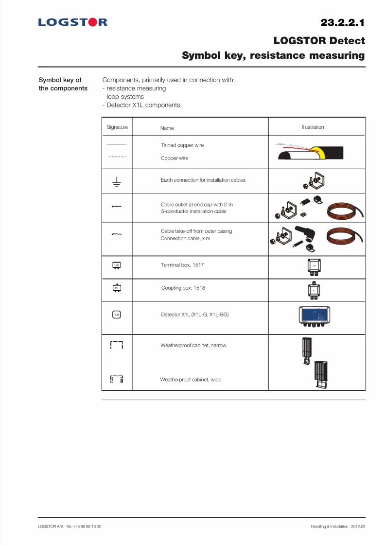
Symbol key of
the components
Components, primarily used in connection with:
- resistance measuring
- loop systems- Detector X1L components
Signature IllustrationName
Tinned copper wire
Copper wire
Earth connection for installation cables
Cable outlet at end cap with 2 m
Cable take-off from outer casing
Terminal box, 15171517
Detector X1L (X1L-G, X1L-BG)X1L
Weatherproof cabinet, narrow
1517
Connection cable, x m
5-conductor installation cable
Coupling box, 1518151
151
Weatherproof cabinet, wide

7/29/2019 23_0 Surveillance System
http://slidepdf.com/reader/full/230-surveillance-system 8/56Handling & Installation · 2012.09 LOGSTOR A/S · Tel. +45 99 66 10 00
23.2.2.2
LOGSTOR Detect
Surveillance diagram, resistance measuring
Examples of
surveillance dia-
grams, made inaccordance with
the symbol key
The diagrams show various connection/combination possibilities related to the use of installa-
tion cables, measuring boxes, and detectors in a system with resistance measuring.
Lw
= max. wire length, incl. branches
Ll= max. wire length in loop, incl. branches
Standard wiring
Passive system
43
1 2
2
43
1
1517
1517
3
3
1
1
5
5
5
5
Lw = max. 500/1000 m Ll = max. 500/1000 m
Standard wiring
Active system
43
1 2
1517
2
15
5
Lw = max. 400/800 m Ll = max. 400/800 m
2
1
1518
X1L
5
TwinPipe
Standard wiring
Active system
43
1 2
2
43
1
1517
1518
3
3
1
1
5
5
5
5
Lw = max. 500/1000 m Ll = max. 500/1000 m
1518
3
3
1
15
5
X1L
Lw/I
= 500 m applies to the distribution pipeline
Lw/I
= 1000 m applies to the transmission pipeline
Lw/I
= 500 m applies to the distribution pipeline
Lw/I
= 1000 m applies to the transmission pipeline
Lw/I
= 400 m applies to the distribution pipeline
Lw/I = 800 m applies to the transmission pipeline

7/29/2019 23_0 Surveillance System
http://slidepdf.com/reader/full/230-surveillance-system 9/56LOGSTOR A/S · Tel. +45 99 66 10 00 Handling & Installation · 2012.09
23.2.2.3
LOGSTOR Detect
Surveillance diagram, resistance measuring
Standard wiring
Transition to
TwinPipe system
43
1 2
2
43
1
1517
5
5
Solution A:
Long TwinPipe runs
Solution B:
Short TwinPipe runs.
If the TwinPipe run is longer than 12 m, solu-
tion A applies.
7/29/2019 23_0 Surveillance System
http://slidepdf.com/reader/full/230-surveillance-system 10/56Handling & Installation · 2012.09 LOGSTOR A/S · Tel. +45 99 66 10 00
23.2.3.1
LOGSTOR Detect
Symbol key, impedance measuring
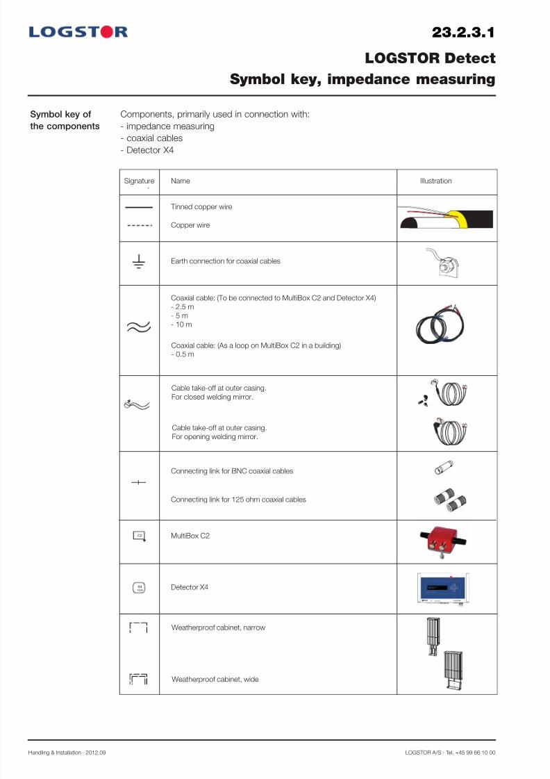
Symbol key of
the components
Signature Illustration.
Name
Tinned copper wire
Copper wire
Earth connection for coaxial cables
Coaxial cable: (To be connected to MultiBox C2 and Detector X4)
- 2.5 m
- 5 m
- 10 m
MultiBox C2C2
Detector X4X41234
Coaxial cable: (As a loop on MultiBox C2 in a building)
- 0.5 m
Cable take-off at outer casing.
For closed welding mirror.
Cable take-off at outer casing.
For opening welding mirror.
Connecting link for 125 ohm coaxial cables
Weatherproof cabinet, narrow
Weatherproof cabinet, wide
Connecting link for BNC coaxial cables
Components, primarily used in connection with:
- impedance measuring
- coaxial cables- Detector X4

7/29/2019 23_0 Surveillance System
http://slidepdf.com/reader/full/230-surveillance-system 11/56LOGSTOR A/S · Tel. +45 99 66 10 00 Handling & Installation · 2012.09
23.2.3.2
LOGSTOR Detect
Surveillance diagram, impedance measuring
Examples of
surveillance
diagrams, madeaccording to the
symbol key
The diagrams show the various connection possibilities/combinations primarily related to the
use of coaxial cables, measurement boxes and detectors in a system with impedance meas-
uring.
Lw
= recommended max. wire length, incl. branches
Lo
= recommended max. wire length, “open” wire, incl. branches
Standard wiring
Two channels per
pipe4
3
1
2
Lw = max. 1000 m Lo = max. 1000 m
C 2
C 2 4.1
3.1
1.1
2.14
3
1
2
X4
1 42 3
*)
C 2
C 2
C 2
C 2
Standard wiring
One channel per
pipe
Lw = max. 1000 m Lo = max. 1000 m
C 2
X4
1 423
1
2
1
2
1.1
2.1
*) C 2
C 2
TwinPipe
Standard wiring
Two channels per pipe, one direc-
tion
Lw = max. 1000 m Lo = max. 500 m
C 2
C 2
C 2
C 2
4
3
1
2
X4
1 423
4
3
4.1
3.1
*) Loop is made, when the wire length of the loop does not exceed 5000 m.
*) Loop is made, when the wire length of the loop does not exceed 5000 m.

7/29/2019 23_0 Surveillance System
http://slidepdf.com/reader/full/230-surveillance-system 12/56Handling & Installation · 2012.09 LOGSTOR A/S · Tel. +45 99 66 10 00
23.2.3.3
LOGSTOR Detect
Surveillance diagram, impedance measuring
Example of tran-
sition from singleto TwinPipe sys-
tem
Due to the measuring technique a take-off
between the single pipe and the TwinPipesystem must always be established.
1 2
Lw = max. 1000 m Lo = max. 500 m
C 2 C
2
X41 423
2 3
41
3
4
3.1
4.1
TwinPipe
Standard wiring
Two channels per pipe, two direc-
tions

7/29/2019 23_0 Surveillance System
http://slidepdf.com/reader/full/230-surveillance-system 13/56LOGSTOR A/S · Tel. +45 99 66 10 00 Handling & Installation · 2012.09
23.3.0.1
Introduction
Contents
Checking alarm wires
Overview
This section describes the installation and check of alarm wires in the surveillance system.
General 23.3.1
The megger 23.3.2
Using the megger. Checking alarm wires 23.3.3

7/29/2019 23_0 Surveillance System
http://slidepdf.com/reader/full/230-surveillance-system 14/56Handling & Installation · 2012.09 LOGSTOR A/S · Tel. +45 99 66 10 00
23.3.1.1
Preparations
Straightening
Repairing wires
Checking alarm wires
General
12
The two copper wires, embedded in the
insulation, are delivered with protection
against damage by winding and fixing themto the insulation by means of staples.
When installing the pipes in the trench follow
the specifications of the wire position in the
surveillance diagram.
Place the pipes so the wires face upwards
(10-to-2-o'clock position), and so the tinned
wires and the copper wires are installed in
pairs opposite each other.
This facilitates the installation and is a must
in systems with pulse measuring and coaxial
cables.
Wind the coiled wires from the countersink
holes in the insulation, when the pipes have
been welded together.
Remove dirt and moisture from the insulation
of the pipe ends.
Straighten the wires and clean the ends with
a cloth of synthetic textile or emery cloth.
Examine the wires for possible damage. If a
wire has been damaged e.g. during removal
of the insulation, remove the insulation
around the wire end and solder a new piece
of wire on as described in the following.
Note! Do not use a gas flame when solder-
ing towards the insulation.
At each joint there must only be one pipe
label and it must face upwards (12 o’clock
position).
In the surveillance systems the alarm wires
are placed at the top of the pipe in order to
achieve i.a.:
- optimum installation conditions
- permanent accessibility of the wires when
establishing branches.

7/29/2019 23_0 Surveillance System
http://slidepdf.com/reader/full/230-surveillance-system 15/56LOGSTOR A/S · Tel. +45 99 66 10 00 Handling & Installation · 2012.09
23.3.2.1
Adjusting the
control instru-
ment
Warning
Checking alarm wires
The megger
0,00
T E S T
V
OFF
SET
UP
Megger MIT320
Ω
Ω
kΩ
1kV
500 V
250 V
M Ω
Ω
0
10
20 3040
50
Never use the megger with connected detectors as the voltage emitted by the megger may
damage the exits of the detectors.
FuseSupply
0,01
T E S T
V
OFF
SET
UP
Megger MIT320
Ω
Ω
kΩ
1kV
500 V
250 V
M Ω
Ω
0
10
2 0 3 040
50
0,01
T E S T
V
OFF
SET
UP
Megger MIT320
Ω
Ω
kΩ
1kV
500 V
250 V
M Ω
Ω
0
10
2030
40
50
Carry out 2 kinds of tests:
1. Measuring the wire resistance to check
that there is good electrical connection
through the connected wires.
2. Measuing the insulation resistance to
check that the wires have been correctly
isolated from the steel pipe (15 mm).
These checks are carried out at each joint
with a wire and insulation resistance tester,
the megger MIT 320.
The megger is zero set by connecting the
alligator clips and activating “Test” in “Ω”
position.

7/29/2019 23_0 Surveillance System
http://slidepdf.com/reader/full/230-surveillance-system 16/56Handling & Installation · 2012.09 LOGSTOR A/S · Tel. +45 99 66 10 00
Preparations for
checking the joint
When beginning the wire installation, con-
nect the wires in the two pipes as shown in
the illustration. Tinned wire to copper wire ineach pipe.
Hereby 2 measuring circuits are established
which must be used to check the wire con-
nections on the subsequent joints.
Naturally, in TwinPipes there are only 1 meas-
uring circuit.
23.3.3.1
Checking alarm wires
Using the megger
Test 1,
wire resistance
1,20
T E S T
V
OFF
SET
UP
Megger MIT320
Ω
Ω
kΩ
1kV
500 V
250 V
M Ω
Ω
0
10
20 3040
50
OFF
SET
Ω
Ω
kΩ
250 V
- Connect the instrument wires to the
cleaned wire ends- Place the switch in measuring range "Ω"
The megger shows the actual ohmic resist-
ance in the wires.
At the beginning of the installation the deflec-
tion is insignificant, but it increases as more
metres of wire are connected.
Resistance measurement: Approx. 1.2 Ω at
100 m 1.5 mm2 wire.
If there is no deflection, there is no connec-
tion.
If the resistance does not correspond to the
actual length, a poor wire connection has
been made in the previous joint.
- Check this joint and repair it.
- Repeat the test.
Check both measuring circuits in the pipes in
this way.
>100,0
T E S T
V
OFF
SET
UP
Megger MIT320
Ω
Ω
kΩ
1kV
500 V
250 V
M Ω
Ω
0
10
20 30
40
50
OFF
SET
Ω
Ω
kΩ
250 V

7/29/2019 23_0 Surveillance System
http://slidepdf.com/reader/full/230-surveillance-system 17/56LOGSTOR A/S · Tel. +45 99 66 10 00 Handling & Installation · 2012.09
23.3.3.2
Test 2b,
insulation
resistance in MΩ
Checking alarm wires
Using the megger
>1000
T E S T
V
OFF
SET
UP
Megger MIT320
Ω
Ω
kΩ
1kV
500 V
250 V
M Ω
MΩ
0
10
20 30
40
50
OFF
SET
Ω
Ω
kΩ
250 V
Note!
Before carrying out this test make sure that
NO dectectors are connected to the pipe
system to avoid damage.
- Place the switch in measuring range:
MΩ, 250 V.
- Connect one instrument wire to one of the
wires in a pipe.
- Hold the other instrument wire against the
steel pipe. Check that there is good electri-
cal connection. Use the weld.
- Press the test knob, until the reading
appears.
- The actual insulation resistance can now be
read
Acceptance value: ≥ 10 MΩ /km wire
To measure a fault location exactly use a
pulse reflectometer.
Test 2a,
insulation
resistance in k Ω
>1000
T E S T
V
OFF
SET
UP
Megger MIT320
Ω
Ω
kΩ
1kV
500 V
250 V
M Ω
kΩ
0
10
20 30
40
50
OFF
SET
Ω
Ω
kΩ
250 V
- Place the switch in measuring range:
k Ω.
- Connect one instrument wire to one of thewires in the pipe.
- Hold the other instrument wire against the
steel pipe. Check that there is good electri-
cal connection. Use the weld.
Read off the insulation resistance.
If the reading is < 1000 k Ω, note the resist-
ance for possible later reference.
If the reading is lower, an incorrect installation
(moisture) has been made in the previouscasing joint.
- Check the joint.
- Remove possible moist foam.
Repeat the test.
- Check all the wires in the joints in this way.
- Now move the instrument to the next pipe
joint.
If the reading is > 1000 k Ω, continue to test
2b.

7/29/2019 23_0 Surveillance System
http://slidepdf.com/reader/full/230-surveillance-system 18/56Handling & Installation · 2012.09 LOGSTOR A/S · Tel. +45 99 66 10 00
23.4.0.1
Introduction
Contents
Connecting alarm wires
Overview
This section contains instructions of wire installation for the various joints and components.
General 23.4.1
Connecting alarm wires in joints for foaming 23.4.2
Connecting alarm wire in joints with insulation shells 23.4.3

7/29/2019 23_0 Surveillance System
http://slidepdf.com/reader/full/230-surveillance-system 19/56LOGSTOR A/S · Tel. +45 99 66 10 00 Handling & Installation · 2012.09
23.4.1.1
Connecting wires
Soldering the
wires
Connecting alarm wires
General
1,5
1 . 5
6
1 . 5
6
Straighten the wires.
Cut the overlapping ends off.
Clean the wire ends with a synthetic textile or
emery cloth.
Place a crimp connector on one of the wires
and crimp it with the crimping tool, jaw width
1.5 mm.
The crimp connector has a stop in the mid-
dle and a “window” for visual control that the
insertion is correct.
Heat the crimp connector with the soldering
iron. When its colour changes and becomes
shiny the temperature is correct.
Add tin solder with resin flux to both ends of
the crimp connector. The soldering has been
carried out correctly, when the tin has been
absorbed in the ends of the crimp connector
and becomes visible.
Now a good electrical connection has also
been established.
Insert the other wire into the crimp connec-tor and crimp it.
A good mechanical connection is now
ensured.
Note! The wires must be tight, i.e. the same
length as between the foam ends.
7/29/2019 23_0 Surveillance System
http://slidepdf.com/reader/full/230-surveillance-system 20/56Handling & Installation · 2012.09 LOGSTOR A/S · Tel. +45 99 66 10 00
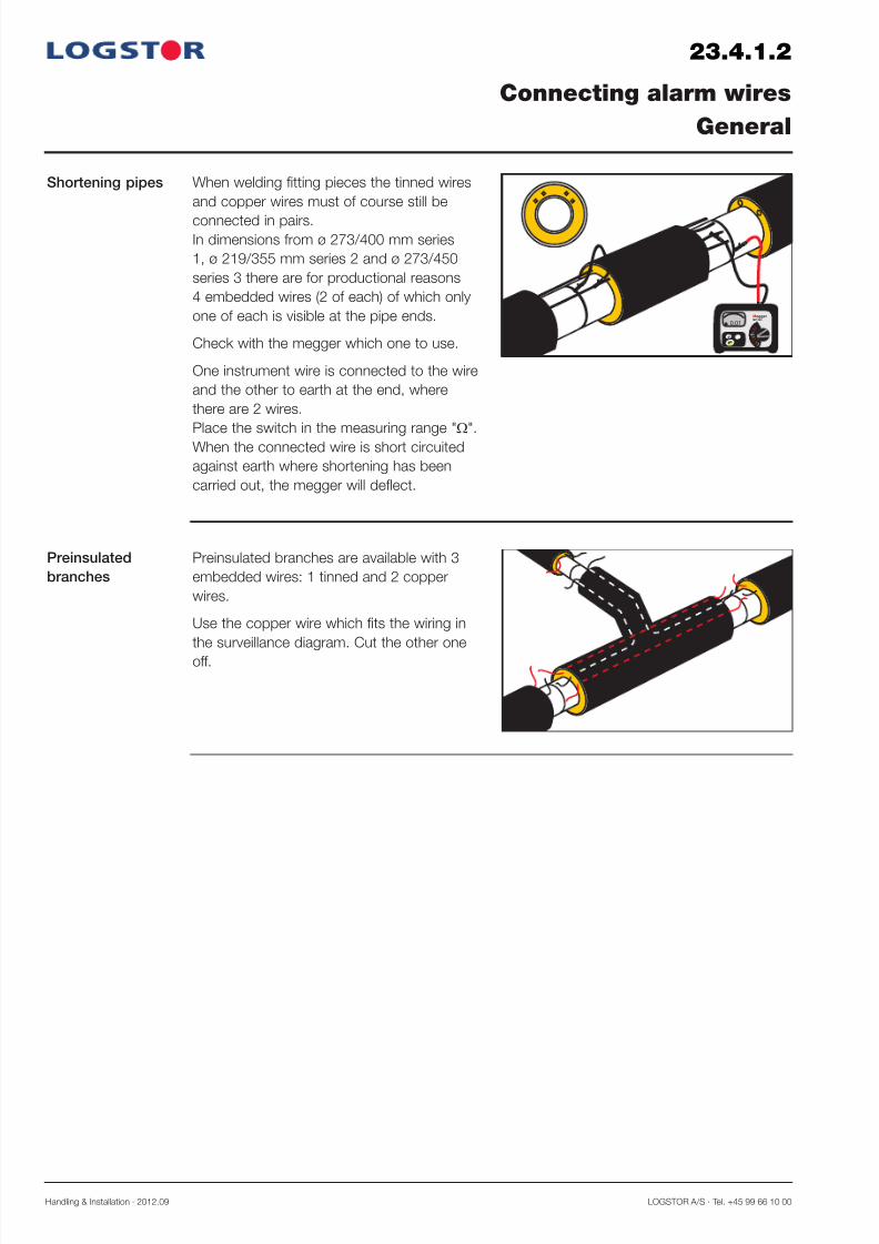
23.4.1.2
Preinsulated
branches
Connecting alarm wires
General
Preinsulated branches are available with 3
embedded wires: 1 tinned and 2 copper
wires.
Use the copper wire which fits the wiring in
the surveillance diagram. Cut the other one
off.
Shortening pipes
0,01
T E S T
V
OFF
SETUP
Megger MIT320
Ω
Ω
kΩ
1kV
500 V
250 V
M Ω
Ω
0
10
20 3040
50
When welding fitting pieces the tinned wires
and copper wires must of course still be
connected in pairs.In dimensions from ø 273/400 mm series
1, ø 219/355 mm series 2 and ø 273/450
series 3 there are for productional reasons
4 embedded wires (2 of each) of which only
one of each is visible at the pipe ends.
Check with the megger which one to use.
One instrument wire is connected to the wire
and the other to earth at the end, where
there are 2 wires.
Place the switch in the measuring range "Ω
".
When the connected wire is short circuited
against earth where shortening has been
carried out, the megger will deflect.

7/29/2019 23_0 Surveillance System
http://slidepdf.com/reader/full/230-surveillance-system 21/56LOGSTOR A/S · Tel. +45 99 66 10 00 Handling & Installation · 2012.09
23.4.1.3
Connecting alarm wires
General
General wiring
in connection
with resistanceand impedance
measuring
A
B
In systems with resistance measuring the alarm wires are connected in a loop (A).
In systems with impedance measuring the wires may be connected in a loop (A) or open (B)
dependent on the actual wire length.In practice this means that the wire closest to the branch is connected to the branch. So there
can be branches on the wire from the detector as well as the wire returning to the detector.
In systems with impedance measuring and alarm wires up to max. 5000 m the wires can be
connected so in principle the tinned wire is always the only one to measure (“open” system).
So all branches are connected to the same wire. The copper wire is primarily used as an aux-
iliary wire and always in branches with loops. See diagram page 23.2.3.2 “Standard wiring.
One channel per pipe”.
Special wiring
in connection
with impedance
measuring
L = max. 5000 m
( )

7/29/2019 23_0 Surveillance System
http://slidepdf.com/reader/full/230-surveillance-system 22/56Handling & Installation · 2012.09 LOGSTOR A/S · Tel. +45 99 66 10 00
23.4.2.1
Connecting alarm wires
Joints for foaming
Straight joints When the tinned wire and the copper wire
have been connected, install each wire in 3
wire holders to ensure correct distance to thepipe.
Fasten the wire holders with a similar number
of strips of crepe tape with a good overlap.
Straight joints
with E-Comps
Extend the wires at E-Comps.
Place the alarm wires in a suitable number
of wire holders, so the distance to the steel
pipe is 15 mm everywhere.
Fasten the wire holders with crepe tape.
Extend the wires at bends.
Apply so many wire holders to the alarm wire
that the wire cannot be pressed against the
steel pipe.
Fasten the wire holders with crepe tape.
Bends
All types of
branchesExtend and adjust the wires at the branches,
so they have the correct distance to the steel
pipe of 15 mm everywhere - also on the
branch pipe piece.
Use a suitable number of wire holders for this
purpose and fasten them with crepe tape.
If the wire closest to the branch is not used
for surveillance, lead it back behind the
branch pipe piece.

7/29/2019 23_0 Surveillance System
http://slidepdf.com/reader/full/230-surveillance-system 23/56LOGSTOR A/S · Tel. +45 99 66 10 00 Handling & Installation · 2012.09
23.4.3.1
Connecting alarm wires
Straight joints with insulation shells
Preparing instal-
lation of insula-
tion shells
Connecting and
fastening wires
D
D
Bend the wires backward to make them rest
evenly on the insulation end and to disable
contact with the steel pipe.
Adapt the insulation shell in accordance with
the instructions for installing the joint type in
question.
Make a slot in the insulation shells and make
sure that the alarm wire does not touch thediffusion barrier, D under the casing.
Adjust, connect and solder the wires as
described in the general section, 23.4.1.
Place the insulation shells and align the
alarm wires on the outside of the shells. Pull
the wires so they do not get in contact with
the steel pipe.
Insertion of wires
in the insulation

7/29/2019 23_0 Surveillance System
http://slidepdf.com/reader/full/230-surveillance-system 24/56Handling & Installation · 2012.09 LOGSTOR A/S · Tel. +45 99 66 10 00
23.4.3.2
Connecting alarm wires
Straight joints with insulation shells
Connecting and
fastening wires,
continued
Fasten the wires to the insulation shells by
means of crepe tape.
7/29/2019 23_0 Surveillance System
http://slidepdf.com/reader/full/230-surveillance-system 25/56LOGSTOR A/S · Tel. +45 99 66 10 00 Handling & Installation · 2012.09
23.5.1.1
Earth connection/
cable take-off
and outlet
Earth connection
Establishing earth connections
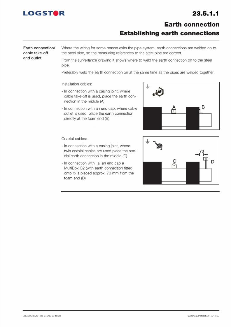
Where the wiring for some reason exits the pipe system, earth connections are welded on to
the steel pipe, so the measuring references to the steel pipe are correct.
From the surveillance drawing it shows where to weld the earth connection on to the steel
pipe.
Preferably weld the earth connection on at the same time as the pipes are welded together.
Installation cables:
- In connection with a casing joint, where
cable take-off is used, place the earth con-
nection in the middle (A)
- In connection with an end cap, where cable
outlet is used, place the earth connectiondirectly at the foam end (B)
A B
Coaxial cables:
- In connection with a casing joint, where
twin coaxial cables are used place the spe-
cial earth connection in the middle (C)
- In connection with i.a. an end cap a
MultiBox C2 (with earth connection fitted
onto it) is placed approx. 70 mm from the
foam end (D)
C DC2
70

7/29/2019 23_0 Surveillance System
http://slidepdf.com/reader/full/230-surveillance-system 26/56Handling & Installation · 2012.09 LOGSTOR A/S · Tel. +45 99 66 10 00
23.6.0.1
Introduction
Contents
Installing cables
Overview
This section contains instructions for installing installation cables and coaxial cables dependent
on the surveillance principle.
Installing installation cables 23.6.1
Installing coaxial cables 23.6.2
Relieving cables 23.6.3
7/29/2019 23_0 Surveillance System
http://slidepdf.com/reader/full/230-surveillance-system 27/56LOGSTOR A/S · Tel. +45 99 66 10 00 Handling & Installation · 2012.09
23.6.1.1
LOGSTOR Detect
Installing installation cables
Cable take-off in
outer casingA
B
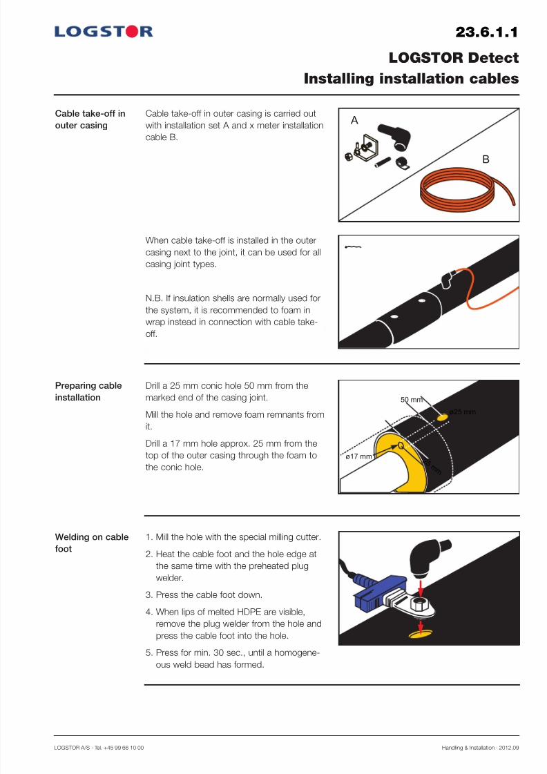
Cable take-off in outer casing is carried out
with installation set A and x meter installation
cable B.
When cable take-off is installed in the outer
casing next to the joint, it can be used for all
casing joint types.
N.B. If insulation shells are normally used for
the system, it is recommended to foam in
wrap instead in connection with cable take-
off.
ø25 mm
2 5 m m
ø17 mm
50 mm
Drill a 25 mm conic hole 50 mm from the
marked end of the casing joint.
Mill the hole and remove foam remnants from
it.
Drill a 17 mm hole approx. 25 mm from the
top of the outer casing through the foam to
the conic hole.
Preparing cable
installation
1. Mill the hole with the special milling cutter.
2. Heat the cable foot and the hole edge at
the same time with the preheated plug
welder.
3. Press the cable foot down.
4. When lips of melted HDPE are visible,
remove the plug welder from the hole and
press the cable foot into the hole.
5. Press for min. 30 sec., until a homogene-
ous weld bead has formed.
Welding on cable
foot
7/29/2019 23_0 Surveillance System
http://slidepdf.com/reader/full/230-surveillance-system 28/56Handling & Installation · 2012.09 LOGSTOR A/S · Tel. +45 99 66 10 00
23.6.1.2
LOGSTOR Detect
Installing installation cables
Earth connection
2 2 0 m m
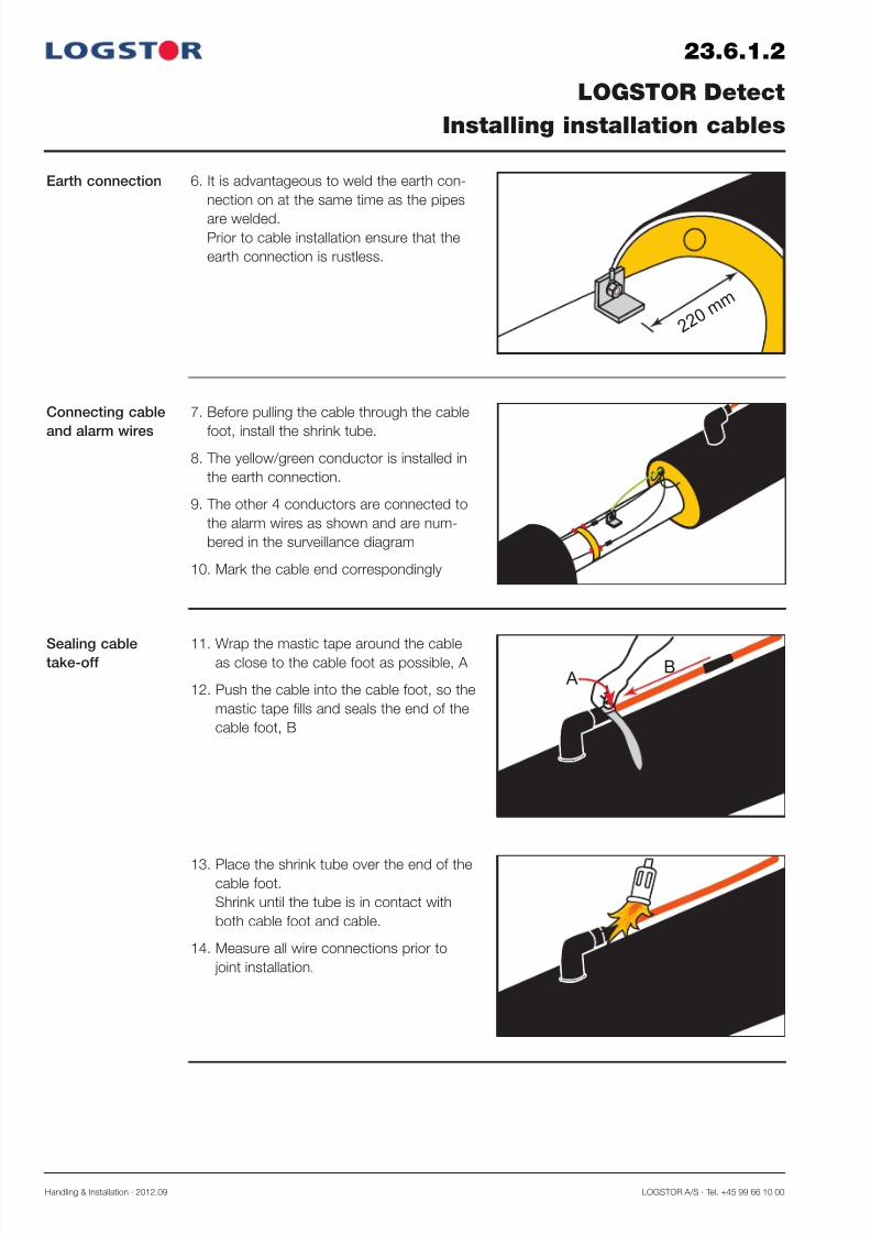
6. It is advantageous to weld the earth con-
nection on at the same time as the pipes
are welded.Prior to cable installation ensure that the
earth connection is rustless.
7. Before pulling the cable through the cable
foot, install the shrink tube.
8. The yellow/green conductor is installed in
the earth connection.
9. The other 4 conductors are connected to
the alarm wires as shown and are num-
bered in the surveillance diagram
10. Mark the cable end correspondingly
Connecting cable
and alarm wires
AB
11. Wrap the mastic tape around the cableas close to the cable foot as possible, A
12. Push the cable into the cable foot, so the
mastic tape fills and seals the end of the
cable foot, B
Sealing cabletake-off
13. Place the shrink tube over the end of thecable foot.
Shrink until the tube is in contact with
both cable foot and cable.
14. Measure all wire connections prior to
joint installation.

7/29/2019 23_0 Surveillance System
http://slidepdf.com/reader/full/230-surveillance-system 29/56LOGSTOR A/S · Tel. +45 99 66 10 00 Handling & Installation · 2012.09
Relieving cables The temperature difference in the pipe sys-
tem will result in movements of the pipes.
Consequently, relieve the cable with a
U-bend before pulling them to the cabinet.
It is recommended to pull the cables
between the pipe system and the cabinet
through e.g. a PVC-duct. It gives a good
protection and facilitates repairs of excava-tion damages and the like.
Measure the connecting point on the pipes in
relation to fix points in the area.
23.6.1.3
LOGSTOR Detect
Installing installation cables

7/29/2019 23_0 Surveillance System
http://slidepdf.com/reader/full/230-surveillance-system 30/56Handling & Installation · 2012.09 LOGSTOR A/S · Tel. +45 99 66 10 00
23.6.1.4
LOGSTOR Detect
Installing installation cables
Cable outlet at
end-cap
Cable outlet at end-caps are carried out with
an installation set and x meter installation
cable.
1. Weld the earth connection onto the steel
pipe close to the insulation.It may be advantageous to weld the pipes
at the same time.
2. Fix the cable shoe to the yellow/green
conductor with the crimp connector.
Earth connection
3. Install the cable shoe in the earth connec-
tion and fasten it securely.
4. Install shrink tubes on the two conductorsto be used, e.g. Nos. 1 and 2, and cut off
the others.
5. Shorten the alarm wires, so the connec-
tion is close to the insulation.
Connection toalarm wires

7/29/2019 23_0 Surveillance System
http://slidepdf.com/reader/full/230-surveillance-system 31/56LOGSTOR A/S · Tel. +45 99 66 10 00 Handling & Installation · 2012.09
23.6.1.5
LOGSTOR Detect
Installing installation cables
Connection to
alarm wires,
continued
6. Connect e.g. conductor No. 2 of the cable
to the tinned wire, and conductor No. 1 to
the copper wire by means of crimp con-nectors.
7. Place the shrink tubes over the crimp con-
nectors and shrink with gas burner.
8. Pull the cable back along the outer casing,so the conductors lie close to the insula-
tion.
9. Make sure that the shrink tubes cover
the uninsulated wires to prevent contact
between the wires and the diffusion bar-
rier, D.
10. Apply mastic to the outer casing and
around the cable.
D
11. Massage the mastic, until it forms a flat
curve.
Sealing the cable
outlet
7/29/2019 23_0 Surveillance System
http://slidepdf.com/reader/full/230-surveillance-system 32/56Handling & Installation · 2012.09 LOGSTOR A/S · Tel. +45 99 66 10 00
23.6.1.6
LOGSTOR Detect
Installing installation cables
Installing end-
caps
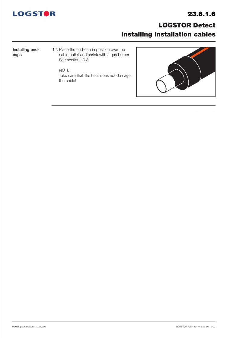
12. Place the end-cap in position over the
cable outlet and shrink with a gas burner.
See section 10.3.
NOTE!
Take care that the heat does not damage
the cable!

7/29/2019 23_0 Surveillance System
http://slidepdf.com/reader/full/230-surveillance-system 33/56LOGSTOR A/S · Tel. +45 99 66 10 00 Handling & Installation · 2012.09
23.6.2.1
Cable installation
Installing coaxial cables
Cable take-off in
outer casing with
closed weldingmirror
Cable take-off in outer casing by means of a
closed welding mirror with the shown instal-
lation set.
When cable take-off is installed in the outer
casing next to the joint, it can be used for all
casing joint types.
N.B. If insulation shells are normally used for
the system, it is recommended to foam in
wrap instead in connection with cable take-
off.
ø25 mm
2 5 m m
ø17 mm
50 mm
Drill a 25 mm conic hole 50 mm from the
marked end of the casing joint.
Mill the hole and remove foam remnants from
it.
Drill a 17 mm hole approx. 25 mm from the
top of the outer casing through the foam to
the conic hole.
Preparing cable
installation
1. Mill the hole with the special milling cutter.
2. Heat the cable foot and the hole edge at
the same time with the preheated plug
welder.
3. Press the cable foot down.
4. When lips of melted HDPE are visible,
remove the plug welder from the hole and
press the cable foot into the hole.
5. Press for min. 30 sec., until a homogene-
ous weld bead has formed.
Welding on cable
foot
7/29/2019 23_0 Surveillance System
http://slidepdf.com/reader/full/230-surveillance-system 34/56Handling & Installation · 2012.09 LOGSTOR A/S · Tel. +45 99 66 10 00
23.6.2.2
Cable installation
Installing coaxial cables
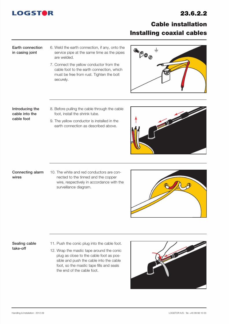
Earth connection
in casing joint
6. Weld the earth connection, if any, onto the
service pipe at the same time as the pipes
are welded.
7. Connect the yellow conductor from the
cable foot to the earth connection, which
must be free from rust. Tighten the bolt
securely.
8. Before pulling the cable through the cable
foot, install the shrink tube.
9. The yellow conductor is installed in the
earth connection as described above.
Introducing the
cable into thecable foot
10. The white and red conductors are con-
nected to the tinned and the copper
wire, respectively in accordance with the
surveillance diagram.
Connecting alarm
wires
11. Push the conic plug into the cable foot.
12. Wrap the mastic tape around the conic
plug as close to the cable foot as pos-
sible and push the cable into the cable
foot, so the mastic tape fills and seals
the end of the cable foot.
Sealing cable
take-off
7/29/2019 23_0 Surveillance System
http://slidepdf.com/reader/full/230-surveillance-system 35/56LOGSTOR A/S · Tel. +45 99 66 10 00 Handling & Installation · 2012.09
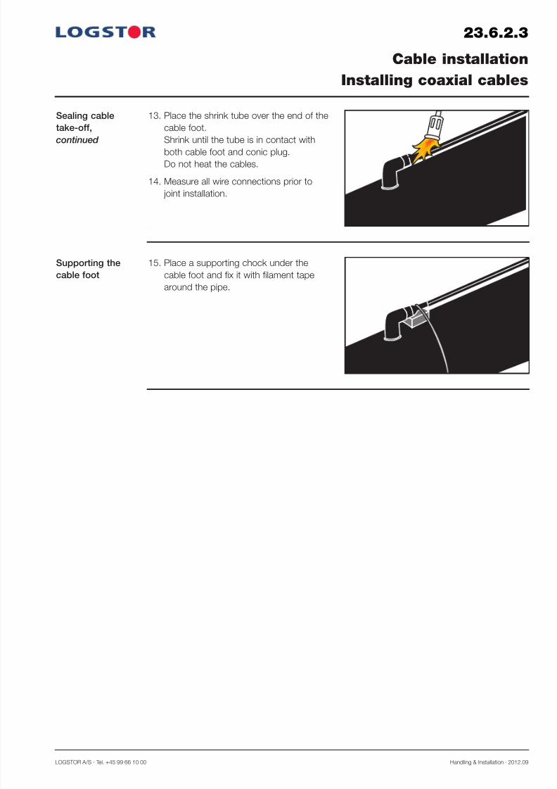
Sealing cable
take-off,
continued
13. Place the shrink tube over the end of the
cable foot.
Shrink until the tube is in contact withboth cable foot and conic plug.
Do not heat the cables.
14. Measure all wire connections prior to
joint installation.
23.6.2.3
Cable installation
Installing coaxial cables
Supporting the
cable foot
15. Place a supporting chock under the
cable foot and fix it with filament tapearound the pipe.

7/29/2019 23_0 Surveillance System
http://slidepdf.com/reader/full/230-surveillance-system 36/56Handling & Installation · 2012.09 LOGSTOR A/S · Tel. +45 99 66 10 00
23.6.2.4
Cable installation
Installing coaxial cables
Cable take-off in
outer casing with
opening, weldingmirror
Cable take-off in outer casing with an open-
ing, welding mirror is carried out with the
shown installation set.
When cable take-off is installed in the outer
casing next to the joint, it can be used for all
casing joint types.
N.B. If insulation shells are normally used for
the system, it is recommended to foam in
wrap instead in connection with cable take-
off.
ø43 mm
2 5 m m
ø17 mm
50 mm
1. Drill a 43 mm conic hole 50 mm from the
marked end of the casing joint.
Mill the hole and remove foam remnants
from it.
2. Drill a 17 mm hole approx. 25 mm from
the top of the outer casing through the
foam to the conic hole.
Preparing cable
installation
3. Weld the earth connection, if any, onto the
service pipe at the same time as the pipesare welded.
4. Connect the yellow conductor from the
cable foot to the earth connection, which
must be free from rust. Tighten the bolt
securely.
Earth connection
in casing joint

7/29/2019 23_0 Surveillance System
http://slidepdf.com/reader/full/230-surveillance-system 37/56LOGSTOR A/S · Tel. +45 99 66 10 00 Handling & Installation · 2012.09
23.6.2.5
Cable installation
Installing coaxial cables
Welding in the
cable foot
5. Pull the 3 wires from the cable foot
through the hole towards the joint.
6. Connect the plug welder to 230 V and
preheat it to 220°C. Open the plug welder,
insert the cable foot, close and heat.
7. When lips of the HDPE-material has
melted on the outer casing and cable foot,
open the plug welder and press the cable
foot down into the melted material.
Keep the cable foot under pressure
approx. 1 minute, until the plastic has
cured.
8. The white and red conductors are con-
nected to the tinned and the copper wire,
respectively in accordance with the surveil-
lance diagram.
9. The yellow conductor is installed in the
earth connection as described above.
Connecting alarm
wires

7/29/2019 23_0 Surveillance System
http://slidepdf.com/reader/full/230-surveillance-system 38/56Handling & Installation · 2012.09 LOGSTOR A/S · Tel. +45 99 66 10 00
23.6.3.1
Cable installation
Relieving cables
Relieving cables The temperature difference in the pipe sys-
tem will result in movements of the pipes.
Consequently, relieve the cable with a
U-bend before pulling them to the cabinet.
It is recommended to pull the cables
between the pipe system and the cabinet
through e.g. a PVC-duct. It gives a good
protection and facilitates repairs of excava-tion damages and the like.
Measure the connecting point on the pipes in
relation to fix points in the area.

7/29/2019 23_0 Surveillance System
http://slidepdf.com/reader/full/230-surveillance-system 39/56LOGSTOR A/S · Tel. +45 99 66 10 00 Handling & Installation · 2012.09
23.6.3.2
Cable installation
Installing cables and connecting links
Overview Cables to be extended in the earth are con-
nected with connecting link and sealed with
mastic and tape.
Connection Mount the couplings of the cables on the
connecting link.
Note! The cable colours must correspond.
Transition from
coaxial cable to
installation cable
1233
To be used when Detector X1L is connectedto coaxial cables.

7/29/2019 23_0 Surveillance System
http://slidepdf.com/reader/full/230-surveillance-system 40/56Handling & Installation · 2012.09 LOGSTOR A/S · Tel. +45 99 66 10 00
23.7.0.1
Introduction
Contents
Connection and coupling boxes
Overview
This section contains installation instructions for connecting boxes and cables dependent on
the surveillance principle.
Coupling in connection with installation cables 23.7.1
Coupling in connection with coaxial cables 23.7.2

7/29/2019 23_0 Surveillance System
http://slidepdf.com/reader/full/230-surveillance-system 41/56LOGSTOR A/S · Tel. +45 99 66 10 00 Handling & Installation · 2012.09
23.7.1.1
Application
Connection/
coupling box,
1518
Connection and coupling boxes
with installation cables
1518
2
2
1
1
5
X1L
This section describes different ways of connecting boxes in a surveillance system with instal-
lation cables.
For a total overview see section 23.2.2, surveillance diagrams for resistance measuring.
The connection box, 1518, is used for elec-
trical separation between Detector X1L and
the pipe system to enable direct resistance
measuring on the alarm wires.
2
2
1
1
5
R
F
5
1 2 5 3 4 1 2 5 3 4
See example of connection in section
23.6.1.4.
LOGSTOR always supplies 5-conductor
cables.
In this case conductors 3 and 4 are cut.
Alternative use
of coupling box,
1518
42
1 2
2
42
1
1518
5 5
1518
The coupling box, 1518, may also be used
to connect a pair of pipes to another or the
same pair of pipes e.g. in a chamber or a
building by means of a jumper cable.

7/29/2019 23_0 Surveillance System
http://slidepdf.com/reader/full/230-surveillance-system 42/56Handling & Installation · 2012.09 LOGSTOR A/S · Tel. +45 99 66 10 00
23.7.1.2
Terminal box,
1517
Box 1517 at the
start/end of a
system
Connection and coupling boxes
with installation cables
1517
2
2
1
1
5
2
1
1
21
2
1517
5
5
R
F
The terminal box, 1517, can be used:
- at the beginning and the end of a system
- as a measuring point along the system
- as a terminal box between two circuits in e.g. a transmission line.
For a total overview see section 23.2.2, surveillance diagrams for resistance measuring.
The terminal box, 1517, used as a measuring
point of a pair of pipes in:
- a building
- a chamber
- a cabinet
2
2
1
1
5
R
F
5
F R
1 2 5 3 4 1 2 5 3 4Loops: 1-2
LOGSTOR always supplies 5-conductor
cables.
In this case conductors 3 and 4 are cut.
See example of connection in section
23.6.1.4.

7/29/2019 23_0 Surveillance System
http://slidepdf.com/reader/full/230-surveillance-system 43/56LOGSTOR A/S · Tel. +45 99 66 10 00 Handling & Installation · 2012.09
23.7.1.3
Box 1517 as a
measuring point
Connection and coupling boxes
with installation cables
43
1 2
2
43
1
1517
5
5
R
F
RF
The terminal box, 1517, used as a measuring
point along the system, dividing it for more
accurate measurements.
4
R
F
5
3
1 2
4
5
3
1 2
F R
1 2 5 3 4 1 2 5 3 4Loops: 1-2
3-4
See example of connection in section
23.6.1.2.

7/29/2019 23_0 Surveillance System
http://slidepdf.com/reader/full/230-surveillance-system 44/56Handling & Installation · 2012.09 LOGSTOR A/S · Tel. +45 99 66 10 00
23.7.1.4
Connection and coupling boxes
with installation cables
Box 1517 as a
double end point
43
1 2
2
43
1
1517
5
5
R
F
RF
The terminal box, 1517, used as a double
end point, separating two individual circuits.
4
R
F
5
3
1 2
4
5
3
1 2
F R
1 2 5 3 4 1 2 5 3 4Loops: 1-3
2-4
See example of connection in section
23.6.1.2.
7/29/2019 23_0 Surveillance System
http://slidepdf.com/reader/full/230-surveillance-system 45/56LOGSTOR A/S · Tel. +45 99 66 10 00 Handling & Installation · 2012.09
23.7.2.1
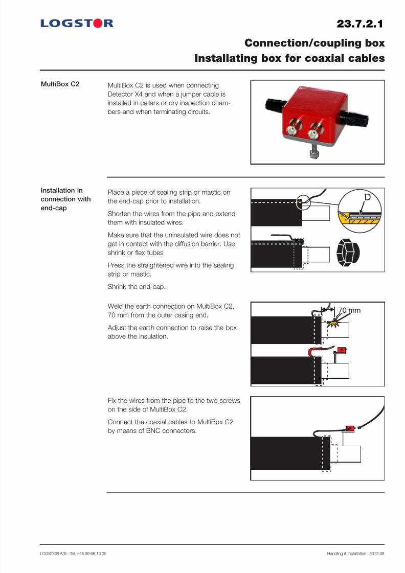
MultiBox C2 is used when connecting
Detector X4 and when a jumper cable is
installed in cellars or dry inspection cham-
bers and when terminating circuits.
Installation in
connection withend-cap
Connection/coupling box
Installating box for coaxial cables
70 mm
MultiBox C2
DPlace a piece of sealing strip or mastic on
the end-cap prior to installation.
Shorten the wires from the pipe and extend
them with insulated wires.
Make sure that the uninsulated wire does not
get in contact with the diffusion barrier. Use
shrink or flex tubes
Press the straightened wire into the sealing
strip or mastic.
Shrink the end-cap.
Weld the earth connection on MultiBox C2,
70 mm from the outer casing end.
Adjust the earth connection to raise the box
above the insulation.
Fix the wires from the pipe to the two screwson the side of MultiBox C2.
Connect the coaxial cables to MultiBox C2
by means of BNC connectors.

7/29/2019 23_0 Surveillance System
http://slidepdf.com/reader/full/230-surveillance-system 46/56Handling & Installation · 2012.09 LOGSTOR A/S · Tel. +45 99 66 10 00
23.8.0.1
Introduction
Contents
Surveillance components
Overview
This section contains installation instructions for the various detectors dependent on the sur-
veillance principle.
Surveillance component for resistance measuring 23.8.1
Surveillance component for impedance measuring 23.8.2

7/29/2019 23_0 Surveillance System
http://slidepdf.com/reader/full/230-surveillance-system 47/56LOGSTOR A/S · Tel. +45 99 66 10 00 Handling & Installation · 2012.09
23.8.1.1
Surveillance components
Resistance measuring
Detector X1L
Description
For resistance measuring the detector, type
X1L is used.
X1L is available in 4 designs dependent on
the pipe system and the requirements to the
surveillance.
It must be installed in a condensation free
environment indoors or in a weatherproof
cabinet.
Standard properties:
- 4 circuits (exits/channels), each with a
range of 7000 m on alarm wires, which are
always in loop (3500 m pipe)
- Can emit a visual as well as an acousticsignal, if the detection level is exceeded
- Is factory-set to a detection level of 300 k Ω
- The level can be adjusted from 1 k Ω to
1 MΩ
- Enclosure class: IP 67
- Ready for connection to 110/230 V by
means of the included, preinstalled trans-
former.
Weight: 0.5 kg
Dimensions: L x W x H: 200 x 110 x 60 mm
Range: 4 x 7,000 m wires, 8 channels (4 loops)
Measurement range - insulation: 1k Ω - 1 MΩ
Alarm transmitter: Optical and acoustic - and with XTool software, relay out-
put
Signal: Network, GPRS, fibre
Enclosure: Polycarbonate, halogen-free - IP 67
Range of application: -20°C to +70°C
Power supply: Transformer 110/230 V AC, 12 V DC - or batteryPower consumption: < 50 m A
Placement: It is recommended to place it in a dry and frostfree
environment
CE approved
Specifications

7/29/2019 23_0 Surveillance System
http://slidepdf.com/reader/full/230-surveillance-system 48/56Handling & Installation · 2012.09 LOGSTOR A/S · Tel. +45 99 66 10 00
23.8.1.2
Surveillance components
Resistance measuring
Diagram with
connections and
functions
F1
110/
230V~
50/60 Hz
110/230V~
50/60 Hz
X1L diagram ( X1L-G ) with GPRS functionality. External XPort for LAN connection.
F1
110/230V~
50/60 Hz
110/
230V~
50/60 Hz
X1L diagram ( X1L-G ) without GPRS functionality. Built-in XPort for LAN connection.

7/29/2019 23_0 Surveillance System
http://slidepdf.com/reader/full/230-surveillance-system 49/56LOGSTOR A/S · Tel. +45 99 66 10 00 Handling & Installation · 2012.09
23.8.1.3
Surveillance components
Resistance measuring
Notation Terminal Pin Wiring Comment
Power T1
1
2
+
-
Primary: 110-230 VAC, secondary: 12 VDC
Battery, Lithium 7.2 VDC, 13 Ah
Relay T2
3
4
5
NO, normally open
COM
NC, normally closed
Max. load 30 VDC, 1A, 125 VAC, 300 mA
Resistance
alarm loop T3
6
7
Alarm loop 1
ReturnFlow
8 Earth Service pipe
9
10
Alarm loop 2
RetunReturn
Resistance
alarm loop
T4
11
12
Alarm loop 3
ReturnFlow
13 Earth Service pipe
14
15
Alarm loop 4
ReturnReturn
WakeUp T5
17
18
19
20
NO
NO
NO
NO
WakeUp inputs
Diagram with
connections and
functions,
continued

7/29/2019 23_0 Surveillance System
http://slidepdf.com/reader/full/230-surveillance-system 50/56Handling & Installation · 2012.09 LOGSTOR A/S · Tel. +45 99 66 10 00
23.8.2.1
Surveillance components
Impedance measuring
Detector X4
Description
For impedance measuring the detector, type
X4 is used.
Product No. 8000 0000 007 024
It must be installed in a condensation free
environment indoors or in a weatherproof
cabinet with thermostat and heating element.
Standard properties:
- X4 has a built-in transformer, 110/230 V
- 4 circuits (exits/channels), each with a range of 5000 m on alarm wires. That equals 5000 m
pipe, provided that a single wire - not a loop - has been used from the measurement box to
the end of the surveilled section.
- The connected pipe section to be measured is surveilled at preset intervals by the built-in
TDR pulse reflectometer
- Measuring accuracy: < 1 m
- Enclosure class: IP 53
- Measuring range: 1 k Ω to 50 MΩ
- All data are stored in the memory
- If a fault is detected, a curve of the ongoing course is automatically generated. This curve
can be transmitted to the surveillance computer
- Standard network connection: LAN - X4 communicates via a GPRS modem (to be purchased separately) or via broadband
- The LCD display i.a. shows:
- Wire resistance, Ω
- Alarm signal
- Date, time
- Error voltage
For installation and protection of detectors
and other components like transient protec-
tions, transformers, GPRS modems, anten-
nas, heating elements, temperature gauges
etc.
L x W x H: 380 x 380 x 210
Enclosure class: IP 66.
Product No. 8000 0000 007 010
Detector cabinet

7/29/2019 23_0 Surveillance System
http://slidepdf.com/reader/full/230-surveillance-system 51/56LOGSTOR A/S · Tel. +45 99 66 10 00 Handling & Installation · 2012.09
23.8.2.2
Surveillance components
Impedance measuring
Weight: 2 kg
Dimensions: L x W x H: 260 x 150 x 90 mm
Range: 4 x 5,000 m wires, 4 channels (2 loops or open)
Measurement range - insulation: 1k Ω - 50 MΩ
Alarm transmitter: Optical and acoustic - and with XTool software, relay out-
put
Communication protocol: TCP/IP
Accuracy: < 1 m, Impulse: TDR 1-5ns
Signal: Network, GPRS, fibre
Enclosure: Aluminium IP 53 (with component cabinet IP 66)
Range of application: -20°C to +80°C
Power supply: Built-in transformer 110/230 V AC, 12 V DCPower consumption: 15 W
Placement: Condensation free - indoors or in a weatherproof cabinet
CE approved
Specifications
Diagram with
connections and
functions
110/230V~
50/60 Hz
X4 diagram
7/29/2019 23_0 Surveillance System
http://slidepdf.com/reader/full/230-surveillance-system 52/56Handling & Installation · 2012.09 LOGSTOR A/S · Tel. +45 99 66 10 00
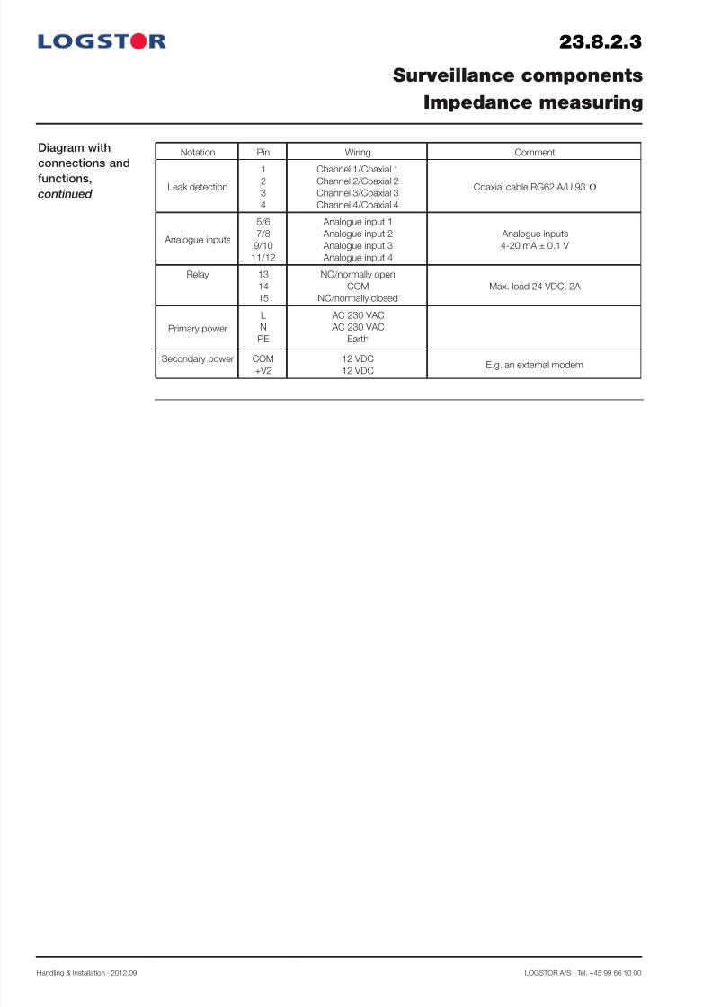
Notation Pin Wiring Comment
Leak detection
1
2
3
4
Channel 1/Coaxial 1
Channel 2/Coaxial 2
Channel 3/Coaxial 3
Channel 4/Coaxial 4
Coaxial cable RG62 A/U 93 Ω
Analogue inputs
5/6
7/8
9/10
11/12
Analogue input 1
Analogue input 2
Analogue input 3
Analogue input 4
Analogue inputs
4-20 mA ± 0.1 V
Relay 13
14
15
NO/normally open
COM
NC/normally closed
Max. load 24 VDC, 2A
Primary power
L
N
PE
AC 230 VAC
AC 230 VAC
Earth
Secondary power COM
+V2
12 VDC
12 VDCE.g. an external modem
Diagram with
connections and
functions,continued
23.8.2.3
Surveillance components
Impedance measuring

7/29/2019 23_0 Surveillance System
http://slidepdf.com/reader/full/230-surveillance-system 53/56LOGSTOR A/S · Tel. +45 99 66 10 00 Handling & Installation · 2012.09
23.9.1.1
Description
Installing weath-
erproof cabinets
Weatherproof cabinets
Installing weatherproof cabinets
574 215
9 0 0
5 0 0
6 2 8
7 0 0
4 0 0
303 155
9 0 0
5 0 0
6 2 8
7 0 0
4 0 0
6728 6718
If components cannot be placed in a build-
ing or the like, install them in a cabinet.
Type no. 6718 (628 x 303 x 155 mm)
Type no. 6728 (628 x 574 x 215 mm).
The weatherproof cabinet is constructed for
individual installation or as a uniform system
built together.
The single cabinets are connected by means
of corrugated nails and a coupling mounting.
Adjust the sole plate after the ground or the
depth of the cable trench.
Place the cabinet with marking on cabinet in
ground.
To avoid moisture ingress fill the lower third
of the cabinet with styropor balls.
Seal the balls with sealing spray, if necessary.

7/29/2019 23_0 Surveillance System
http://slidepdf.com/reader/full/230-surveillance-system 54/56Handling & Installation · 2012.09 LOGSTOR A/S · Tel. +45 99 66 10 00
For surveillance of chambers, low-lying areas
etc. Detector A1e is used.
The unit has 12 separate entry points and
can i.a. register:
- moisture
- temperature
- water level
- velocity of incoming water
- pressure and temperature in the insulated
pipes
In addition A1e has the same functions as
X1L for resistance measuring alarm wires in
preinsulated pipe systems. For this purpose
A1e has two circuits with a range of 5000 m
each (2500 m pipes in loop).
Detector A1e
Description
23.10.0.1
LOGSTOR Detect
Surveillance of chambers
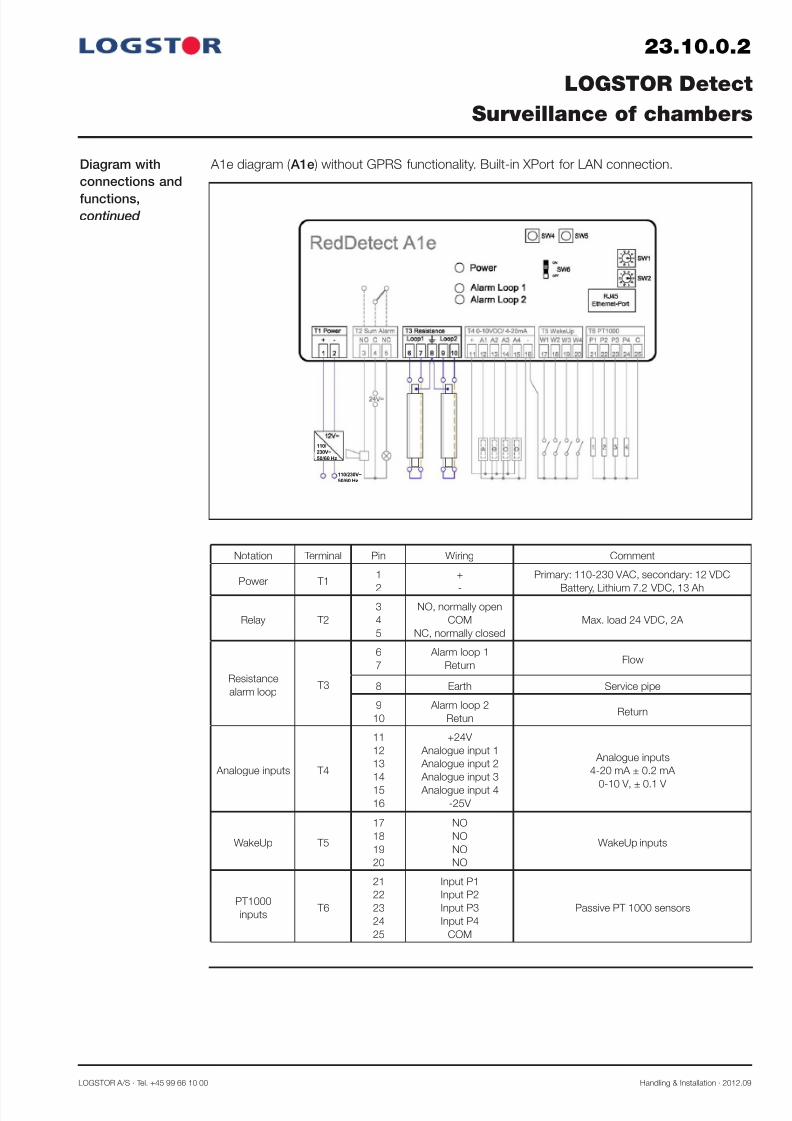
Diagram with
connections and
functions
110/230V~
50/60 Hz
110/230V~
50/60 Hz
A1e diagram ( A1e-G, A1e-BG ) with GPRS functionality. External XPort for LAN connection.
7/29/2019 23_0 Surveillance System
http://slidepdf.com/reader/full/230-surveillance-system 55/56LOGSTOR A/S · Tel. +45 99 66 10 00 Handling & Installation · 2012.09
Notation Terminal Pin Wiring Comment
Power T11
2
+
-
Primary: 110-230 VAC, secondary: 12 VDC
Battery, Lithium 7.2 VDC, 13 Ah
Relay T2
3
4
5
NO, normally open
COM
NC, normally closed
Max. load 24 VDC, 2A
Resistance
alarm loop T3
6
7
Alarm loop 1
ReturnFlow
8 Earth Service pipe
9
10
Alarm loop 2
RetunReturn
Analogue inputs T4
11
12
13
14
15
16
+24V
Analogue input 1
Analogue input 2
Analogue input 3
Analogue input 4
-25V
Analogue inputs
4-20 mA ± 0.2 mA
0-10 V, ± 0.1 V
WakeUp T5
17
18
19
20
NO
NO
NO
NO
WakeUp inputs
PT1000
inputs T6
21
22
23
24
25
Input P1
Input P2
Input P3
Input P4
COM
Passive PT 1000 sensors
23.10.0.2
LOGSTOR Detect
Surveillance of chambers
Diagram with
connections and
functions,continued
110/230V~
50/60 Hz
110/
230V~
50/60 Hz
A1e diagram ( A1e ) without GPRS functionality. Built-in XPort for LAN connection.

7/29/2019 23_0 Surveillance System
http://slidepdf.com/reader/full/230-surveillance-system 56/56