22420 - book 2 - section 13 roadways - draft
TRANSCRIPT

Request For Proposal US 550 / 160 Connection South NHPP 5501-029, Sub Account 22420 Book 2 – Technical Requirements
Section 13 – Roadways
Request for Proposal 13-1 Final July 12, 2019
13.0 ROADWAYS
This Section 13 includes the requirements for the Roadway Work for the US 550/160 Connection South Design Build Project (Project). This Work shall be completed in accordance with the Contract Documents.
13.1 Administrative Requirements
13.1.1. Standards
The Contractor shall design and construct the Project in accordance with the requirements of the standards in the documents listed in Table 13-1 and those referenced in Book 3. The Contractor shall use the latest adopted edition at the time of the Proposal Due Date except for the American Association of State Highway and Transportation Officials (AASHTO) A Policy on Geometric Design of Highways and Streets, 6th Edition (PGDHS, 2011).
13.1.1.1 US 550, US 160, Ramp A, Ramp B, and Frontage Road
Table 13-1. Standards for US 550, US 160, Ramp A, Ramp B, and Frontage Road
Author or Agency Title
Request for Proposal US 550/160 Connection South
Roadway Criteria Table (Exhibit 13-A to this Section 13)
American Association of State Highway and Transportation Officials (AASHTO)
A Policy on Geometric Design of Highways and Streets, 6th Edition (PGDHS, 2011)
AASHTO Roadside Design Guide
Colorado Department of Transportation (CDOT)
Roadway Design Guide
CDOT Standard Plans, M&S Standards
CDOT Standard Specifications for Road and Bridge Construction
Federal Highway Administration (FHWA) FHWA-CFL/TD-11-003, Wildlife Crossing Structures Handbook, Design and Evaluation in North America
International Code Council (ICC) International Fire Code (IFC)
National Cooperative Highway Research Program (NCHRP)
Report 672 Roundabouts: An Informational Guide, second edition
State of Colorado State Highway Access Code
13.1.1.2 Local Roadways
Local Roadways include La Plata County Roads CR 219 and CR 220, and other non-CDOT Roadways impacted by the Project.
Roadways controlled or maintained by Local Agencies other than CDOT shall be designed and constructed according to the Local Agency’s standard and requirements. In addition to the documents referenced in Table 13-1 and Book 3, Local Agency manuals and standards are in Table 13-2.

Request For Proposal US 550 / 160 Connection South NHPP 5501-029, Sub Account 22420 Book 2 – Technical Requirements
Section 13 – Roadways
Request for Proposal 13-2 Final July 12, 2019
Table 13-2. Standards for Local Roadways
Author or Agency Title
Request for Proposal US 550/160 Connection South
Roadway Design Criteria Table (Exhibit 13-B to this Section 13)
La Plata County La Plata County Code Development Standards and Specifications
13.2 Design Requirements
13.2.1. Submittals
All submittals shall be prepared, Reviewed, and submitted in accordance with the requirements set forth in Book 2, Section 3.
13.2.2. General Design Requirements by Project Element
13.2.2.1 Webb Property Grading
(Note: All slopes stated herein are in terms of horizontal: vertical)
Grading on the Webb Ranch within the temporary Easements and Project ROW from station 981+ to 989+ shall include a berm that is 10 feet in height from the Roadway finished surface with a 15-foot flat area in front of the berm using a maximum of 2:1 front slope on the US 550 side meeting stabilization requirements, 5-foot top sloped to drain back onto the Webb Ranch, and a maximum 3:1 backslope. The berm is not required if the Roadway finished surface is 10 feet below the existing surface within the temporary Easement.
13.2.2.2 Webb Property Stock Pond
A stock pond shall be graded beyond the berm on the backside within the temporary Easement. See Book 2, Section 12, for additional drainage requirements for the stock pond. An example configuration for the Webb property stock pond is provided in the Reference Documents.
13.2.2.3 Existing Signalized Intersection at US 160 and US 550
The intersection of US 160 and the existing US 550 alignment shall be reconfigured to include 10-foot outside Shoulders, two 12-foot through lanes, and 4-foot inside Shoulders with a raised median. The deceleration lane for Ramp A shall be extended as shown in Book 2, Section 1.
The raised median shall terminate to the east of the existing intersection location when the existing flow patterns can no longer be maintained. The raised median to the west of the existing intersection location shall terminate to match the existing raised median when the existing lane configuration can be maintained. Book 2, Section 12, has additional drainage requirements for the reconfiguration.
The existing raised turn and median islands shall be removed. Book 2, Section 14, has additional requirements for signing, striping, and signalization removal.

Request For Proposal US 550 / 160 Connection South NHPP 5501-029, Sub Account 22420 Book 2 – Technical Requirements
Section 13 – Roadways
Request for Proposal 13-3 Final July 12, 2019
13.2.3. Cross Slope and Superelevation
13.2.3.1 Normal Cross Slope
All new and reconstructed pavement sections shall have a normal cross slope of 2%.
When overlay areas are needed, the sections where the existing cross slope is equal to or greater than 2%, the Contractor shall maintain the existing pavement cross slope. For overlay sections where the existing cross slope is less than 2%, the cross slope shall be built up through the use of a variable thickness overlay to a minimum of 2%.
13.2.3.2 Superelevation Rates
Superelevation transitions for US 550 shall be designed based on the typical sections (number of lanes). Superelevation transition design shall comply with the design criteria and methodology of the current AASHTO PGDHS, 2011, CDOT Standard Plans, M&S Standards, and the CDOT Roadway Design Guide.
Superelevation diagrams shall be provided in the Roadway plans to verify that edge profiles (at the location of the Shoulder/lane line) meet design criteria. Superelevation transitions shall be modified if necessary to meet these criteria.
Superelevation transitions shall be designed to eliminate 0.0% cross slopes on Bridge decks or on profile crest and sag curves where grades flatter than 0.5% occur.
13.2.4. Stopping Sight Distance
Stopping sight distances and decision sight distances shall meet or exceed the requirements of Exhibit 13-A in this Section. Stopping sight distances shall be determined in accordance with the CDOT Roadway Design Guide and AASHTO PGDHS, 2011.
13.2.5. Fill and Cut Slopes and Clear Zones
The Contractor shall design cut and fill slopes to obtain clear zones and avoid the need for guardrail wherever possible. Where clear zones cannot be obtained within CDOT Right-of-Way (ROW), guardrail shall be required.
Clear zones shall be designed in accordance with the recommendations of the AASHTO Roadside Design Guide and a clear zone of 30 feet shall be used per Table 3-1 Note A. The horizontal curve adjustment factor shall be calculated per Table 3-2. All other guidelines within the AASHTO Roadside Design Guide shall apply.
13.2.5.1 Roadside Slopes Adjacent to Pavement
The Point of Slope Selection (POSS) is defined as the location at which the Roadside slope, also known as the z-slope, adjacent to the pavement ends and the cut or fill slope begins. Width and slope of the area between the edge of pavement (EOP) (or curb and gutter, or Sidewalk) and the POSS shall be as follows:
1. US 550: 12 feet minimum at a 6:1 slope
2. Ramp B: 6 feet minimum at a 6:1 slope
3. Frontage Road: 6 feet minimum at a 6:1 slope
4. La Plata County Roads: 8 feet at 6:1 slope

Request For Proposal US 550 / 160 Connection South NHPP 5501-029, Sub Account 22420 Book 2 – Technical Requirements
Section 13 – Roadways
Request for Proposal 13-4 Final July 12, 2019
13.2.5.2 Fill Slopes
Fill slope areas shall be designed with ditches and storm sewer as necessary to prevent Roadside and slope drainage from flowing onto adjacent properties.
Fill slopes and height beyond the POSS shall be designed and constructed in accordance with the following priorities:
1. Use 6:1 slopes where fill heights are less than 2 feet and match with existing conditions that can be obtained within the Project limits.
2. Use 4:1 slopes where fill heights are greater than 2 feet but less than 10 feet and match with existing conditions that can be obtained within the Project limits.
3. Use 3:1 slopes where fill heights are less than 10 feet and slopes steeper than 4:1 are required to match existing conditions within the Project limits.
4. Use 3:1 slopes where fill heights exceed 10 feet, match with existing conditions can be obtained within the Project limits, and clear zone can be obtained within the Project limits.
5. Where the above conditions cannot be obtained, the Contractor may use any of the following design approaches.
A. Use 3:1 slopes with barrier protection.
B. Use retaining walls, as necessary, with barrier protection to match with existing conditions within the Project limits. Where retaining walls are used, locate to avoid maintenance areas less than 10 feet in width with a maximum 6:1 cross slope between the face of wall and ROW or permanent Easement (PE) line, fence line, or other obstruction.
13.2.5.3 Cut Slopes
There are three different native materials that will be encountered with the Project. The three materials consist of surficial soil, terrace alluvial gravel, and bedrock of the Animas Formation, as defined in Book 2, Section 10. The surficial soil is at the top near existing ground, the terrace alluvial gravel is in the middle, and the bedrock is below the terrace alluvial gravel. Each of the soil layers have different requirements for cut slopes. In certain instances, all three soil types will be encountered.
All tops of cut slopes at the existing ground shall be rounded to provide a pleasing appearance.
Cut slopes in surficial soil beyond the POSS shall be designed and constructed in accordance with the following priorities:
1. Cut slopes shall be transitioned at the match with the 6:1 slopes adjacent to Roadway pavement in such a manner to comply with the recommendations of the clear zone requirements and the AASHTO Roadside Design Guide.
2. The bottom of the Roadside ditch must be a minimum of 1 foot below the Base Course per Book 2, Section 10, and meet freeboard requirements per Book 2, Section 12.
3. Use 4:1 or flatter slopes for cut slopes where matching with existing conditions can be obtained within the Project limits.
4. Use 3:1 slopes for cut slopes where such slopes steeper than 4:1 are necessary to match with existing conditions within the Project limits.
5. Where the above conditions cannot be obtained, the Contractor may use any of the following design approaches.

Request For Proposal US 550 / 160 Connection South NHPP 5501-029, Sub Account 22420 Book 2 – Technical Requirements
Section 13 – Roadways
Request for Proposal 13-5 Final July 12, 2019
A. Use 3:1 foreslopes with barrier protection.
B. Use retaining walls, as necessary, to match with existing conditions within the Project limits.
Cut slopes in the terrace alluvial gravel beyond the POSS shall be designed and constructed in accordance with the following:
1. Cut slopes shall be transitioned at the match with the 6:1 slopes adjacent to Roadway pavement in such a manner to comply with the recommendations of the clear zone requirements and the AASHTO Roadside Design Guide.
2. The bottom of the Roadside ditch shall meet freeboard requirements per Book 2, Section 12.
3. Use 2:1 or flatter backslopes. Slopes shall comply with the slope stabilization requirements of Book 2, Section 10.
Cut slopes in the bedrock in the Animas Formation beyond the POSS shall be designed and constructed in accordance with the following priorities:
1. Cut slopes shall be transitioned at the match with the 6:1 slopes adjacent to Roadway pavement in such a manner to comply with the recommendations of the clear zone requirements and the AASHTO Roadside Design Guide.
2. The bottom of the Roadside ditch shall be a minimum of 1 foot below the Base Course per Book 2, Section 10, and meet freeboard requirements per Book 2, Section 12.
3. Use 3:1 or flatter slopes for cut slopes.
4. Use retaining walls, as necessary, to match with existing conditions within the Project limits.
13.2.5.4 Fill Material within Project ROW
Excess fill material may be placed within Project ROW with and accepted ATC.
The fill shall be from suitable material acquired from excavation within the Project limits and shall meet all erosion and sedimentation control requirements and drainage requirements per Book 2, Section 12.
The slopes shall be 3:1 or flatter with a maximum fill height of 10 feet measured from the lowest point along the existing ground. These areas shall be finely graded and all edges shall be rounded to provide a pleasing appearance. The grading shall also meet the AASHTO PGDHS, 2011 requirements for sight distance.
13.2.5.5 Retaining Walls
Refer to Book 2, Section 15, for retaining wall requirements. Retaining walls shall be used as necessary. Where retaining walls are used, locate to avoid maintenance areas less than 10 feet in width with a maximum 6:1 cross slope between the wall and ROW or PE line, fence line, or other obstruction
13.2.6. Guardrail
All Guardrail Type 3 W Beam shall be Midwest Guardrail System (MGS) 31-inch with steel posts. Guardrail Type 3 W Beam shall include hot mix asphalt (HMA) as shown on M-606-1. Wooden curb and earthen shoulder is not allowed.
Where guardrail is required along the inside Shoulder of US 550, a minimum 2-foot offset to the face of the guardrail shall be maintained per M-606-1, note 3.

Request For Proposal US 550 / 160 Connection South NHPP 5501-029, Sub Account 22420 Book 2 – Technical Requirements
Section 13 – Roadways
Request for Proposal 13-6 Final July 12, 2019
Guardrail is required along both edges of the inside Shoulders to protect vehicles within the median cross over at station 835+.
13.2.7. Barrier
All concrete barriers shall be cast-in-place. Precast barriers are not allowed for permanent installations. All concrete barriers shall be Guardrail Type 9 Single Slope Barrier.
A concrete median barrier is required north of CR 220 to the raised median at the roundabout.
13.2.8. End Terminals
All end terminals shall be MASH compliant.
13.2.9. Roundabouts
A roundabout shall be constructed south of the existing Bridge over US 160 to connect the Grandview Interchange Bridge, US 550, and Ramp B. The roundabout shall be designed according to NCHRP Report 672 Roundabouts: An Informational Guide, second edition, and according to the following requirements:
1. Number of lanes: The roundabout shall have two-lane entries and exits for US 550 and the Bridge, and a one-lane entry and exit at Ramp B. The existing lanes across the Bridge shall be reconfigured to match the number of lanes at the roundabout.
2. Design vehicle: The roundabout shall accommodate a WB-67 vehicle for all movements.
3. Truck apron: Provide a truck apron to accommodate a WB-67 vehicle traveling in the inside lane. The truck apron shall slope outward at 1% to 2%. Provide a 2-inch to 3-inch sloping curb between the truck apron and circulatory Roadway, as shown in NCHRP Report 672 Exhibit 6-78. The pattern and color of the truck apron shall match the existing truck apron on the roundabout across the Bridge. The truck apron thickness and base course under it shall be designed by the contractor’s geotechnical engineer.
4. Inscribed circle diameter: The inscribed circle diameter shall be between 165 and 220 feet.
5. Entry width: The entry width shall be between 24 and 30 feet for two-lane entries, and shall be a minimum of 12 feet for the one-lane entry.
6. Circulatory Roadway width: The width of each lane in the circulatory Roadway shall be between 14 and 16 feet.
7. Entry radius: The entry radius shall be 65 feet minimum for the two-lane entries, and 50 feet minimum for the one-lane entry.
8. Entry path overlap: To avoid entry path overlap, all two-lane entrances shall have a minimum 20-foot-long straight segment, measured along the center stripe of the approach Roadway that is tangent to the stripe in the circulatory Roadway.
9. Exit radius: All exit radii shall be greater than 100 feet.
10. Fastest path: The fastest path shall be drawn for all entries according to NCHRP Report 672 Section 6.7.1.1. The speed for R1 of the fastest path shall be 30 mph to 25 mph for the two-lane entries and 25 mph to 20 mph for the one-lane entry. Use equation 3-7 from AASHTO PGDHS, 2011 to calculate the speed.
11. Spiral striping: The roundabout shall be striped so that the outside lane is forced to exit onto US 550 southbound and onto the Bridge northbound.

Request For Proposal US 550 / 160 Connection South NHPP 5501-029, Sub Account 22420 Book 2 – Technical Requirements
Section 13 – Roadways
Request for Proposal 13-7 Final July 12, 2019
12. Curb: Place Curb and Gutter Type 2 (Section II-B) on all outside edges of the roundabout, and place Curb and Gutter Type 2 (Section I-B) on all splitter islands. On the northbound US 550 entry, the outside curb shall begin at least 380 feet from the yield line. The outside Shoulder of the northbound entry shall taper from 10 feet to 0 from the beginning of the curb to the beginning of the entry curve. At the north entry and exit, the curb shall tie into the existing curb on the Bridge. For all other entries and exits, the curb shall extend at least through the entry or exit curve.
13. Treatment for high-speed approaches: The splitter island on the approach from northbound US 550 shall be at least 200 feet long. There shall be 3 successively tightening reversing curves approaching the roundabout on northbound US 550, such that the lateral offset is at least 23 feet, as shown in NCHRP Report 672 Exhibit 6-70.
14. Grade: The maximum grade of the circulatory Roadway shall be 3%. The maximum profile grade of US 550 shall be 3%, 600 feet from the center of the inscribed circle. This requirement is not ATC eligible.
15. See Book 2, Section 17, for landscaping requirements within the roundabout.
16. Components of the FAST anti-icing/de-icing system shall be installed on the existing and proposed roundabouts in accordance with Book 2, Section 19 and Book 2, Section 19, Appendix 1. The Contractor is responsible for integrating the FAST anti-icing/de-icing system into all components of the Roadway and the roundabouts.
13.2.10. Vertical Profile
Through the Webb Ranch property, the Roadway surface course elevation shall not exceed the maximum elevations listed in Table 13-3. See the Webb Ranch Property Exhibit 5 in the Reference Documents for the layout of lines 1, 2, and 3.
Table 13-3 Maximum Proposed Pavement Elevations
Line
Begin Point (NW Corner of Barn)
End Point Maximum Proposed Pavement
Elevation (ft.)*
Begin Northing Begin Easting End Northing End Easting
Line 1 1208697.90 2318424.73 1210213.57 2317235.08 6731.61
Line 2 1208697.90 2318424.73 1211345.51 2318112.45 6733.13
Line 3 1208697.90 2318424.73 1212662.87 2318866.15 6766.64
*The intent of the maximum elevations is to ensure the view shed requirements for the Webb property are met.
13.2.11. US 550 Mainline Transition to Existing
At the terminus of the proposed four-lane Basic Configuration limits in accordance to Book 2, Section 1, provide a transition to the existing two-lane US 550 that meets the requirements for a design speed of 55 mph. If the Project limits are extended beyond the Basic Configuration by ARE #2, the same criteria for transitioning to the existing two-lane US 550 must meet a design speed of 55 mph.

Request For Proposal US 550 / 160 Connection South NHPP 5501-029, Sub Account 22420 Book 2 – Technical Requirements
Section 13 – Roadways
Request for Proposal 13-8 Final July 12, 2019
13.2.12. Maintenance Access Vehicle Pad for Variable Message Sign
See Book 2, Section 19, for requirements.
13.2.13. Maintenance Access Road for FAST Anti-Icing/De-icing Pump House(s)
See Book 2, Section 19, Appendix 1 for requirements.
13.2.14. Design Exceptions
13.2.14.1 Design Exception Process
Design exceptions shall be submitted to CDOT for Approval prior to the submittal of the Pre-RFC Documents. Design exceptions may be subject to the Approval of FHWA. Design exceptions that require Approvals beyond CDOT, may require additional time for Approval. Delays incurred from said Approvals are non-compensable and shall not justify any additional time to the schedule.
The Contractor shall comply with the following requirements when requesting a design exception:
1. The Contractor shall submit design exception requests in the form of a letter addressed to the CDOT Project Director for Approval prior to the submittal of Pre-RFC Documents.
2. The design exception request shall consist of the following items:
A. A letter identifying the exception(s) by number, Project number, location, and status (new submittal, resubmittal, etc.).
B. A completed CDOT Form 464 – Design Exception Variance Request, Exhibit 13-C.
C. Supporting documentation indicating the justification for the design exception. Justification shall address the following items:
i. Site conditions of the exception.
ii. Compelling reason for the exception, including which standard is not being met. If the exception affects any other standards, state what will be done to mitigate the effects of the exception.
iii. Effects of the exception on safety and operation of the facility.
iv. Previous crash history near the location of the exception.
v. Calculations estimating the cost of attaining the design standard and costs of exception as proposed.
vi. Effect on scenic, historical, or other environmental features.
D. Plan and profile drawings depicting the exception.
13.3 Construction Requirements
13.3.1. Median Cover Material
Median cover material for all raised medians on mainline US 550 and mainline US 160 shall match the Aesthetics of the corridor via a concrete median cover material. The Contractor shall submit to CDOT a 4-foot by 4-foot test panel for the median cover material for Acceptance for pattern and color.

Request For Proposal US 550 / 160 Connection South NHPP 5501-029, Sub Account 22420 Book 2 – Technical Requirements
Section 13 – Roadways
Request for Proposal 13-9 Final July 12, 2019
13.3.2. Safety Edge
The Contractor’s design shall include safety edges. Safety edge shall be required on all mainline US 550 pavement, overlay areas (as required), ramp pavement, local Roadway pavement, and Frontage Road pavement. Safety edge is not required in front of guardrail, adjacent to median barrier, and adjacent to curb and gutter.
13.3.3. Shouldering Material
Shouldering Material is required along the inside pavement edge for the inside Shoulder of US 550 for 4 feet in width per the requirements in Book 2, Section 10.
Shouldering Material is not required along the outside pavement edge for the outside Shoulder of US 550. The Contractor may place shouldering Material outside the edge of pavement in lieu of topsoil for 4 feet in width per the requirements in Book 2, Section 10.
13.3.4. Water Wells
The Contractor shall remove and abandon any water wells within properties acquired by the Project in accordance with Book 2, Section 8, and the CDOT Standard Specifications for Road and Bridge Construction, Section 202.
See Book 2, Section 8, for additional information.
13.3.5. Fencing
13.3.5.1 Temporary Fencing
Provide temporary fencing according to ROW acquisition agreements per Book 2, Section 8, to protect adjacent private property, livestock containment, and other property owner requirements.
Livestock may be pastured in various fields adjacent to the Project during construction. In order to protect and control livestock, the Contractor shall install and maintain temporary fence at locations as specified in Book 2, Section 8, during construction. The Contractor shall maintain the temporary fence in such condition that it is capable of performing its intended function until such time as the permanent fence is completed. The Contractor shall give the landowner 30 Days written notice before any existing fence or gates are removed unless otherwise noted in Book 2, Section 8.
In remaining areas, temporary fencing shall be considered to control construction operations and to avoid impacts beyond ROW limits. Temporary fence shall be placed as required in any other Section of Book 2.
13.3.5.2 Permanent Fencing
The Contractor shall provide permanent ROW fencing of the types and at the locations shown in Table 13-4. See Book 2, Section 8, for additional requirements.
There shall be no gaps in the deer fencing along the US 550 corridor especially when there is a change in grade at wildlife underpass (as described in Book 2, Section 1), small mammal crossings, and at Bridge locations. Avoid abrupt angles where the deer fence transitions at the wildlife underpass(s), small mammal crossings, and at the Bridges. Deer fence shall tie to all gates, game ramps, deer guards, and access control fence along the Project ROW.

Request For Proposal US 550 / 160 Connection South NHPP 5501-029, Sub Account 22420 Book 2 – Technical Requirements
Section 13 – Roadways
Request for Proposal 13-10 Final July 12, 2019
At the FCDC (Mason Lateral) ditch locations, provide a minimum horizontal offset of 15 feet between the top of the ditch and any ROW and/or deer fencing to allow for maintenance and trash removal. Any ROW and/or Deer fencing shall not cross perpendicular through the Mason Lateral ditch. Any fencing shall not span open sections of the Mason Lateral without the use of a piped section. See Exhibit 6-B for additional information.
Table 13-4 Permanent Fencing
Location
Type Remarks
US 550 ROW Deer Fence Per CDOT Standard M-607-4
Between the Frontage Road and US 550
Deer Fence Per CDOT Standard M-607-4
Wildlife Crossings (Wildlife Underpass and Small Mammal Crossings)
Deer Fence Per CDOT Standard M-607-4
Wildlife Crossing Access Openings at ROW
Barbed Wire With Metal Posts (Smooth Strand Wire - Top
and Bottom)
Per CDOT Standard M 607-1 and the top and bottom
strands per 710.01 without the barbs
Frontage Road ROW Barbed Wire With Metal Posts
(Smooth Strand Wire - Top and Bottom)
Per CDOT Standard M 607-1 and the top and bottom
strands per 710.01 without the barbs
Gulch A and Gulch B Bridges (Continuous Underneath)
Deer Fence Per CDOT Standard M-607-4
13.3.6. Gates
An 8-foot-wide pedestrian gate shall be placed at each deer guard location to match the height of the deer fence.
An 8-foot-wide gate for maintenance access shall be placed at the wildlife underpass(s), both sides of US 550 to match the height of the deer fence.
See Book 2, Section 8, for locations of vehicle gates across access Roads.
13.3.7. Game Ramps
Game ramps shall be placed at intervals of 4 per mile, 2 each side of US 550, and per CDOT Standard M-607-4. See Book 2, Section 5, for additional requirements. The locations of game ramps shall be submitted to CDOT for Approval prior to the RFC Documents submittal.
13.3.8. Deer Guards
Deer guards shall be placed at the ends of all curb return radii at all private and county Road accesses off of mainline US 550 where the deer fence is placed. Deer guards that are within CDOT and La Plata County snow removal maintenance areas shall be designed per the Contract Documents. See Book 2, Section 8, Exhibit 8-B, for specific landowner requirements. All other deer guards shall meet HL93 loading requirements.

Request For Proposal US 550 / 160 Connection South NHPP 5501-029, Sub Account 22420 Book 2 – Technical Requirements
Section 13 – Roadways
Request for Proposal 13-11 Final July 12, 2019
Deer guards shall not include wings to tie to the deer fencing. Instead, the deer fence shall abut the deer guard and run continuous along the outside edges (i.e turn fence at a 90 degree angle perpendicular to the deer guard and run entire length of the deer guard).
At driveway accesses, the pavement section from US 550 shall continue to the front side of the deer guards.
13.3.9. Small Mammal Crossings
See Book 2, Section 1, Book 2, Section 5, and Book 2, Section 12, for requirements. The location of the small mammal crossings shall be submitted to CDOT for Approval prior to the RFC Documents submittal.
13.3.10. Wildlife Underpass
A wildlife underpass shall be placed at station 958+. Barrier and/or guardrail shall not be placed along the Frontage Road in this location. A 10-foot flat area shall be provided at the openings of the underpass with a maximum slope of 10:1. Grading between the Frontage Road and the underpass shall not exceed 4:1.
An additional wildlife underpass is included with the AREs as defined in Book 2, Section 1. The underpass shall be placed a minimum distance of one mile, south from the underpass at station 958+. The location of the second wildlife underpass shall be submitted to CDOT for Approval prior to the RFC Documents submittal if placed as part of an ARE. The Approval process will include CDOT’s coordination with Colorado Parks and Wildlife (CPW).
See Book 2, Section 5, and Book 2, Section15, for additional requirements.
13.3.11. Mailboxes
Single use mailboxes shall be reset and replaced per CDOT Standard M-210-1.
Existing community mailbox Structures shall be surveyed for existing conditions and shall be reset in the same condition on new concrete foundations at their new locations. Any damage incurred to the mailbox Structure shall be the responsibility of the Contractor.
Placement of mailboxes shall be coordinated with CDOT. The final location will include CDOT’s coordination with the United States Postal Service.
13.4 Deliverables
The Contractor shall submit the following to CDOT for Review, Acceptance, or Approval:
Table 13-5 Deliverables
Deliverables Review,
Acceptance, or Approval
Schedule
Design exceptions (if applicable) Approval Prior to the Pre-RFC Documents submittal
Median cover material test panel Acceptance Prior to placement of median cover material
Field locations of game ramps Approval Prior to the RFC Documents submittal
Request For Proposal US 550 / 160 Connection South NHPP 5501-029, Sub Account 22420 Book 2 – Technical Requirements
Section 13 – Roadways
Request for Proposal 13-12 Final July 12, 2019
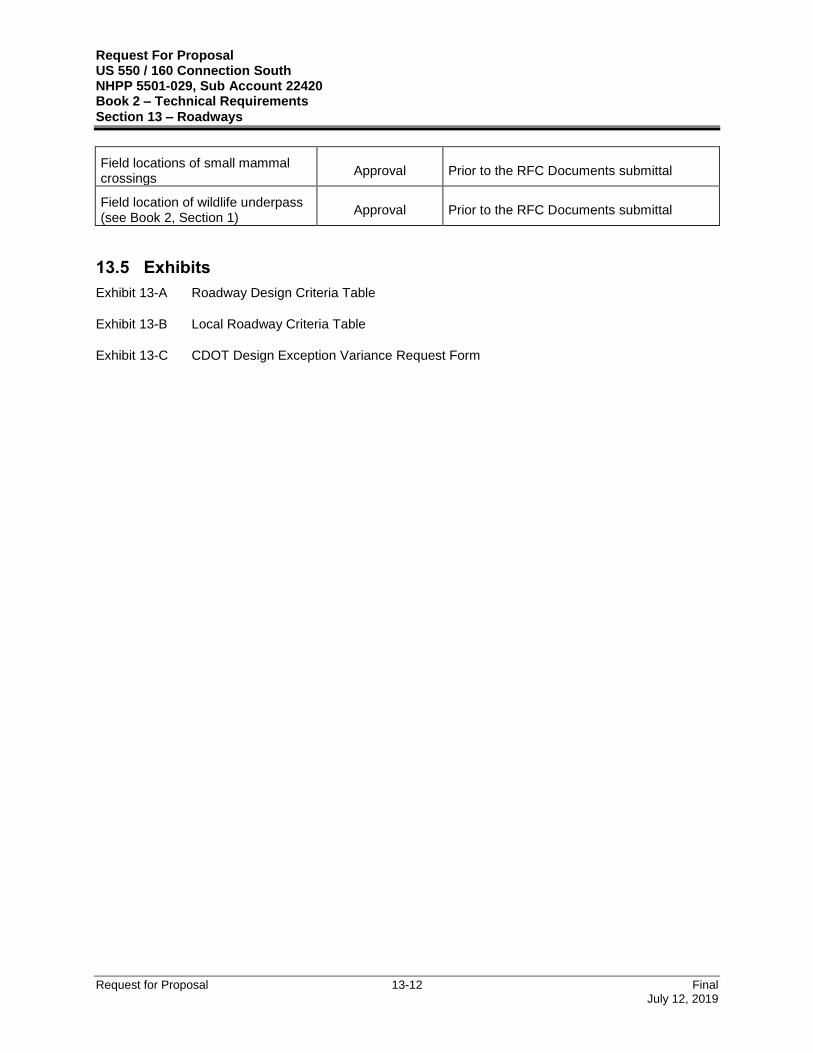
Field locations of small mammal crossings
Approval Prior to the RFC Documents submittal
Field location of wildlife underpass (see Book 2, Section 1)
Approval Prior to the RFC Documents submittal
13.5 Exhibits
Exhibit 13-A Roadway Design Criteria Table
Exhibit 13-B Local Roadway Criteria Table
Exhibit 13-C CDOT Design Exception Variance Request Form

Request For Proposal US 550 / 160 Connection South NHPP 5501-029, Sub Account 22420 Book 2 – Technical Requirements
Section 13 – Roadways
Request for Proposal 13-13 Final July 12, 2019
Exhibit 13-A – Roadway Design Criteria
Criteria US 550 Mainline
South of CR 220 – ARE #2
US 550 Mainline North of CR 220
US 160 Ramp A
Ramp B Connection
to Roundabout
Frontage Road
US 550 Roundabout
Remarks
Design Criteria & Controls
Roadway Classification
Rural Principal Arterial
Rural Principal Arterial
Non-Rural Principal Highway
N/A N/A Rural
Collector Rural Principal
Arterial
Design Speed (mph)
70
60
(1)
55
45
(2)
55 25 25 35 (3) (4)
Posted Speed (mph)
65
55
(1)
50 40 (2)
50
N/A N/A 30 N/A
Terrain Rolling Rolling Rolling Rolling Rolling Rolling Rolling
Horizontal Alignment
eMAX (%) 6% 6%
N/A
Match Existing
N/A
Match Existing
6% 6% (4)
Axis of Rotation PGL PGL
HCL (6)
N/A
Match Existing
N/A
Match Existing
HCL HCL (4)

Request For Proposal US 550 / 160 Connection South NHPP 5501-029, Sub Account 22420 Book 2 – Technical Requirements
Section 13 – Roadways
Request for Proposal 13-14 Final July 12, 2019
Criteria US 550 Mainline
South of CR 220 – ARE #2
US 550 Mainline North of CR 220
US 160 Ramp A
Ramp B Connection
to Roundabout
Frontage Road
US 550 Roundabout
Remarks
Minimum Radius (ft.)
2040
1330
(1)
1060
643
(2)
N/A
Match Existing
N/A
Match Existing
144 340 (4)
PGDHS, 2011 Table, 3-9
Note: Based on maximum super elevation and design speed.
Maximum Superelevation Cross Slope at CR 220 Intersection (%)
N/A 4.00%*
N/A
Match Existing
N/A
Match Existing
N/A N/A N/A
Using Emax, 6% Tables.
*CDOT Project Requirement for maximum cross slope at intersections
Maximum Superelvation Cross Slope at Bridges (%)
N/A 3.50%*
N/A
Match Existing
N/A
Match Existing
N/A N/A N/A
Using Emax, 6% Tables.
*CDOT Project Requirement for maximum cross slope at Bridges
Use of Spirals Permitted Permitted N/A N/A N/A N/A N/A
Use spirals is permitted when recommended in PGDHS, 2011 Table 3-20.
Vertical Alignment
Minimum Grade (%)
0.50% 0.50%
N/A
Match Existing
N/A
Match Existing
0.50% 0.50% (4)

Request For Proposal US 550 / 160 Connection South NHPP 5501-029, Sub Account 22420 Book 2 – Technical Requirements
Section 13 – Roadways
Request for Proposal 13-15 Final July 12, 2019
Criteria US 550 Mainline
South of CR 220 – ARE #2
US 550 Mainline North of CR 220
US 160 Ramp A
Ramp B Connection
to Roundabout
Frontage Road
US 550 Roundabout
Remarks
Maximum Grade (%)
4.00%
4.50%*
(2)
N/A
Match Existing
N/A
Match Existing
4.50%* 5.00%
3.00%*
(3)
CDOT Roadway Design Guide 3.3.3 and Table 3-4. Note: Based on rolling terrain
*CDOT Project Requirement
Minimum K Value, Crest
247
151
(1)
114
61
(2)
N/A
Match Existing
N/A
Match Existing
12 29 (4) PGDHS, 2011 Table 3-34
Minimum K Value, Sag
181
136
(1)
115
79
(2)
N/A
Match Existing
N/A
Match Existing
26 49 (4) PGDHS, 2011 Table 3-36
Sight Distance (SD)
Stopping Sight Distance (SSD) (ft.)
730
570
(1)
495
360
(2)
425 155 155 250 (4)
PGDHS, 2011 Table 3-1, use PGDHS, 2011 Table 3-2 for SSD on Grades
Note: Not adjusted for grade. Allow horizontal sight distance across barriers. Use 3d graphical solutions for areas with vertical curvature. Glare screen not allowed.

Request For Proposal US 550 / 160 Connection South NHPP 5501-029, Sub Account 22420 Book 2 – Technical Requirements
Section 13 – Roadways
Request for Proposal 13-16 Final July 12, 2019
Criteria US 550 Mainline
South of CR 220 – ARE #2
US 550 Mainline North of CR 220
US 160 Ramp A
Ramp B Connection
to Roundabout
Frontage Road
US 550 Roundabout
Remarks
Vertical Clearance
Overhead Sign Structures
18 ft. 6 in.* 18 ft. 6 in.* 18 ft. 6 in.* 18 ft. 6 in.* N/A N/A N/A
*CDOT Project Requirement for Overhead Sign Structures
Cross Section
Lane Width (ft.) 12 12 12 12 12 12 (4) CDOT Roadway Design Guide Table 4-1
Inside Shoulder (ft.)
4 (5) 4 (5)
8 (6)
4
4
N/A N/A (4)
CDOT Roadway Design Guide Table 4-1
Outside Shoulder (ft.)
10
4 (7) 10
10
8
Varies
Match Existing
2 (4) CDOT Roadway Design Guide
Table 4-1
Normal Cross-Slope (%)
2% 2% Match
Existing Match
Existing 2% 2% (4)
CDOT Roadway Design Guide 4.1.2
Clear Zone (ft.) 30 22 22 22 8
8 16
AASHTO Roadside Design Guide, Table 3-1
Design Vehicle WB-67 WB-67 WB-67 WB-67 WB-67
WB-67
WB-67
Intersections at Grade
Acceleration Length (ft.)
Varies Varies Varies Varies N/A N/A (4)

Request For Proposal US 550 / 160 Connection South NHPP 5501-029, Sub Account 22420 Book 2 – Technical Requirements
Section 13 – Roadways
Request for Proposal 13-17 Final July 12, 2019
Criteria US 550 Mainline
South of CR 220 – ARE #2
US 550 Mainline North of CR 220
US 160 Ramp A
Ramp B Connection
to Roundabout
Frontage Road
US 550 Roundabout
Remarks
Deceleration Length (ft.)
Varies Varies Varies Varies N/A N/A (4)
Redirect Taper Rate
70:1
60:1
(1)
55:1
45:1 (2) 50:1 N/A N/A N/A (4)
State of Colorado State Highway Access Code
Note: For lane shifts
Min. Return Curve Radius
25 25 N/A N/A N/A 25 N/A
CDOT Standard Plans, M&S Standards, M-203-1
Notes:
(1) Design speed change at station 916+ for 60 mph from 70 mph at the beginning of the Project per ARE #2
(2) Design speed change at station 953+ for 55 mph per ARE #2. Basic Configuration design speed at station 940+ is 55 mph with design speed change at station 1023+ for 45 mph.
(3) Design speed change at station 1033+ for 35 mph prior to Roundabout
(4) Per National Cooperative Highway Research Program (NCHRP) Report 672 Roundabouts: An Informational Guide, second edition and this Book 2, Section 13.2.8
(5) At locations with depressed median
(6) At locations with barrier separated median
(7) With auxiliary lanes

Request For Proposal US 550 / 160 Connection South NHPP 5501-029, Sub Account 22420 Book 2 – Technical Requirements
Section 13 – Roadways
Request for Proposal 13-18 Final July 12, 2019
Exhibit 13-B – Local Roadway Criteria
Criteria
CR 219 South
(La Plata County) – ARE #2
CR 219 North
(La Plata County) – ARE #2
CR 220
(La Plata County)
Bardin Drive (La Plata County) – ARE #2
Eagle View Drive
(Private) – ARE #2
Eagle Block Access
(Business) Remarks
Roadway Classification
Minor Collector Minor
Collector Minor Arterial Local Access Local Access Local Access
Design Speed (mph) 35 35 45 25 20 20
Posted Speed (mph) 30 30 35 25 N/A N/A
eMAX Normal Crown Normal Crown 6% Normal Crown Normal Crown Normal Crown
Minimum Radius (ft.) 500 50 1000 50 50 30
Minimum Stopping Sight Distance (SSD) (ft.)
250 250 360 155 115 115 PGDHS, 2011 Table 3-1, use PGDHS, 2011 Table 3-2 for SSD on Grades
Minimum Profile Grade
0.50% 0.50% 0.50% 0.50% 0.50% 0.50%
Maximum Profile Grade
4.0% 4.0%
4.0%
4.0% Desired
12.0% Max. *
N/A
Match Existing
4.0% Desired 10.0% Max.*
* To tie to existing grades
Minimum K Value, Crest
10 Min. *
29 Desired
20 Min. *
29 Desired 61
6 Min. *
12 Desired
N/A
Match Existing
7 * To tie to existing grades
Minimum K Value, Sag
18 Min. *
49 Desired 49 79
26
N/A
Match Existing
4.7 Min. *
17 Desired * To tie to existing grades

Request For Proposal US 550 / 160 Connection South NHPP 5501-029, Sub Account 22420 Book 2 – Technical Requirements
Section 13 – Roadways
Request for Proposal 13-19 Final July 12, 2019
Criteria
CR 219 South
(La Plata County) – ARE #2
CR 219 North
(La Plata County) – ARE #2
CR 220
(La Plata County)
Bardin Drive (La Plata County) – ARE #2
Eagle View Drive
(Private) – ARE #2
Eagle Block Access
(Business) Remarks
Number of Thru Lanes
2 2 2 2
N/A
Match
Existing
2
Lane Width (ft.) 12 12 12 12 10 (20 total
width) 12
Minimum Shoulder Width (ft)
4 4 4 4
N/A
Match Existing
N/A
Redirect Taper N/A N/A 12:1 N/A N/A N/A
Clear Zone Width (ft.) 12 12 16 8 8 8
Surface Treatment HMA HMA HMA HMA Gravel HMA
Design Vehicle WB-67 WB-67 WB-67 WB-67 WB-67 WB-67

Request For Proposal US 550 / 160 Connection South NHPP 5501-029, Sub Account 22420 Book 2 – Technical Requirements
Section 13 – Roadways
Request for Proposal 13-20 Final July 12, 2019
Exhibit 13-C – CDOT Design Exception Variance Request Form