22.1 scope · 2017-08-18 · visual examination may be conducted. the surface being examined will...
TRANSCRIPT


Wild Goose Gas Storage CPUC Audit Response Attachments
A.1. EMERGENCY VALVE INSPECTION FORM
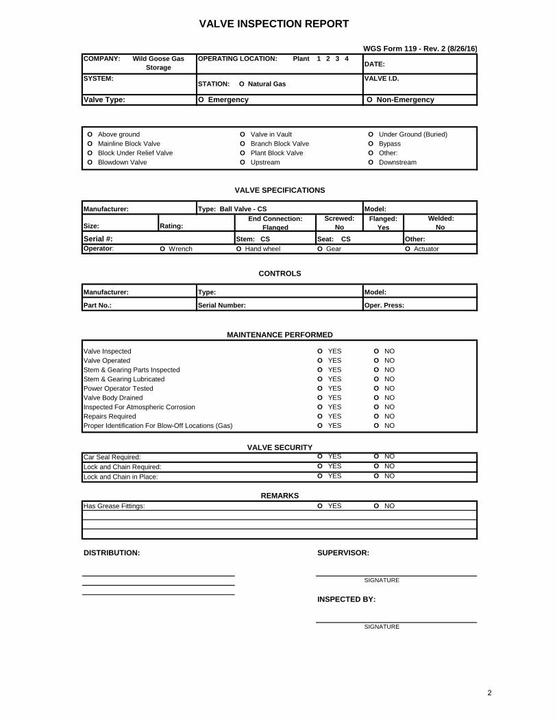
A.1. WGS FORM 119 082616
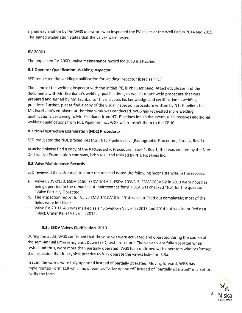
A.2. VALVE MAINTENANCE RECORDS
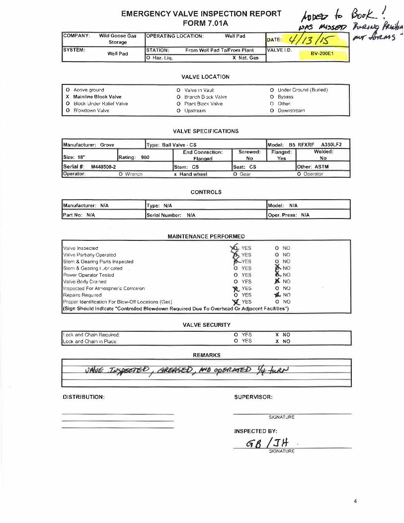
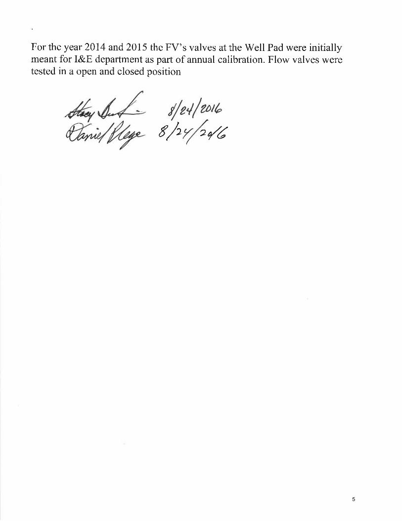
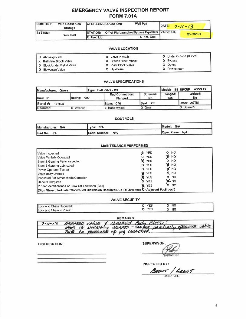
A.2. ESDV-4002-2 2015 FORM 7.01AA.2. BV-200 E1 2015 FORM 7.01AA.2. FV VALVES WELL PAD OPERATOR EXPLANATION 082416A.2. BV-200D1 2013 FORM 7.01A
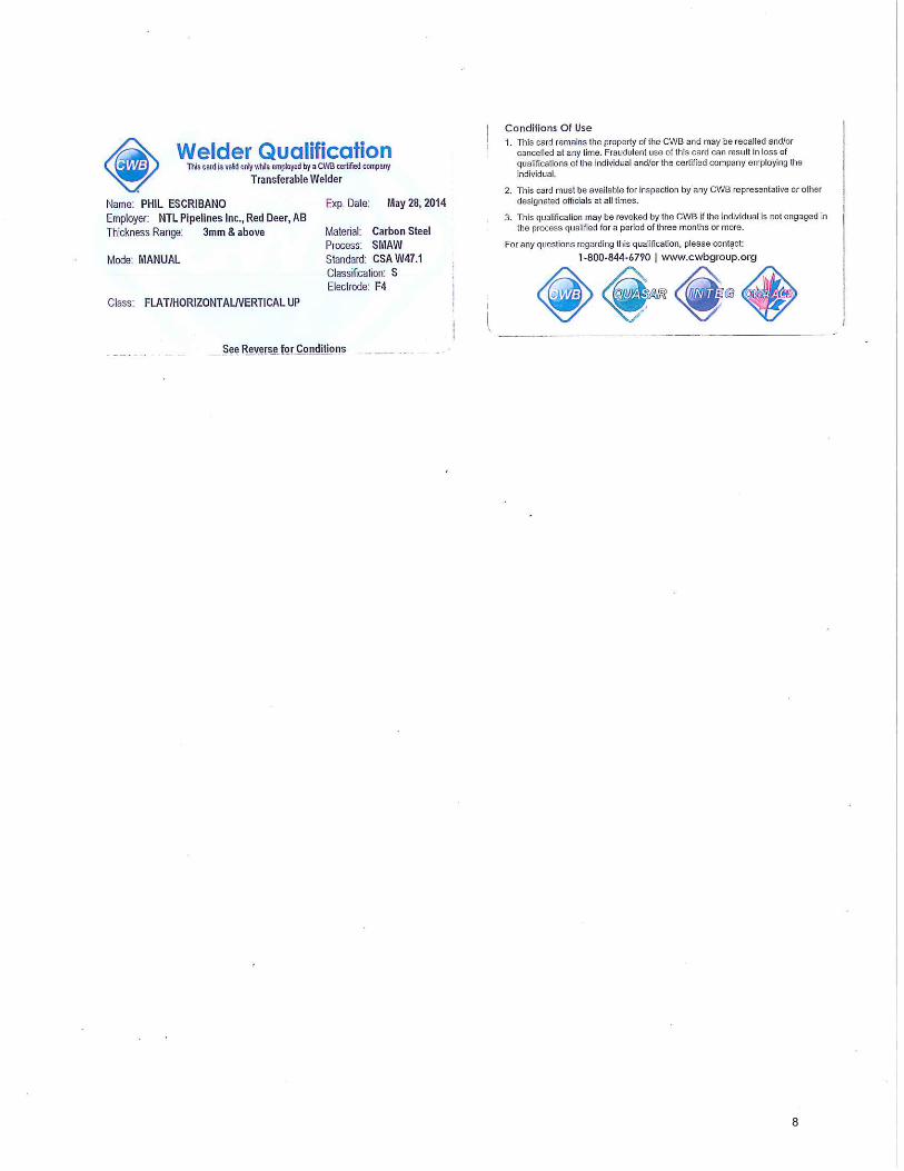
B.1. OPERATOR QUALIFICATION: WELDING INSPECTOR
B.1. PHIL ESCRIBANO CWB 083014B.1. PHIL ESCRIBANO CWB 052814B.1. NTL VISUAL INSPECTION PROCEDURE - PIPELINE MANUALB.1. PHIL ESCRIBANO TACK WELD 072512
B.2. NON- DESTRUCTIVE EXAMINATION (NDE) PROCEDURES
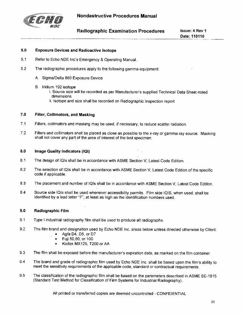
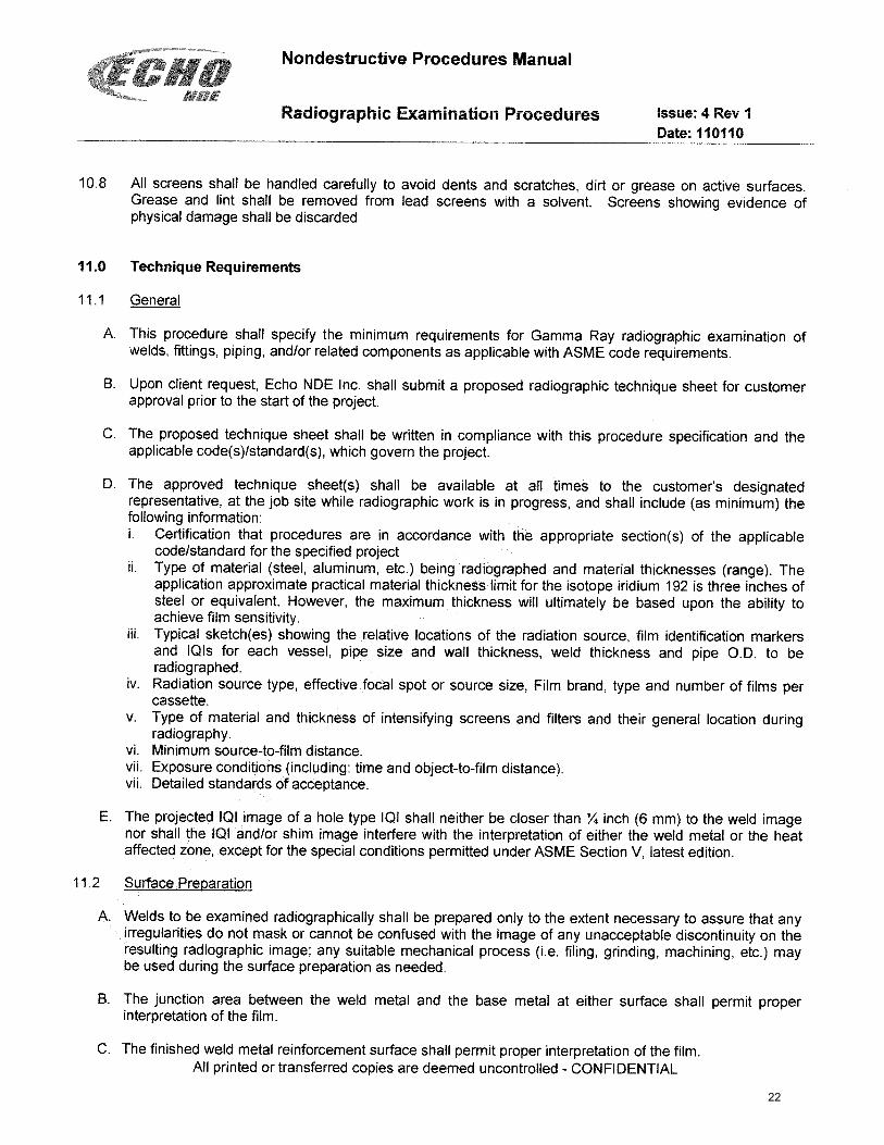
B.2. RADIOGRAPHIC PROCEDURE ISSUE 4 REV 1
1
COMPANY: DATE:
SYSTEM: VALVE I.D.
Valve Type: O Emergency O Non-Emergency
Screwed: No
Flanged: Yes
Welded: No
Serial #: Other:O Actuator
O YES O NOO YES O NOO YES O NOO YES O NOO YES O NOO YES O NOO YES O NOO YES O NOO YES O NO
O YES O NOO YES O NOO YES O NO
O YES O NO
SIGNATURE
SIGNATURE
VALVE INSPECTION REPORT
Plant 1 2 3 4OPERATING LOCATION: Wild Goose Gas Storage
STATION: O Natural Gas
WGS Form 119 - Rev. 2 (8/26/16)
O Above ground O Under Ground (Buried) O Valve in Vault O Bypass O Other: O Plant Block Valve O Downstream
Model:
VALVE SPECIFICATIONS
Manufacturer: Type: Ball Valve - CS
O Mainline Block Valve O Block Under Relief Valve
O Branch Block Valve
End Connection: Flanged
Stem: CS
O Upstream
Car Seal Required:
O Blowdown Valve
Size: Rating:
Stem & Gearing Lubricated
Part No.:
Valve Body Drained
DISTRIBUTION:
Power Operator Tested
Repairs RequiredProper Identification For Blow-Off Locations (Gas)
Serial Number:
Valve OperatedStem & Gearing Parts Inspected
CONTROLS
Model: Manufacturer: Type:
INSPECTED BY:
VALVE SECURITY
Lock and Chain Required:Lock and Chain in Place:
REMARKS
SUPERVISOR:
Seat: CS
MAINTENANCE PERFORMED
Valve Inspected
Has Grease Fittings:
Oper. Press:
Operator: O Wrench O Hand wheel O Gear
Inspected For Atmospheric Corrosion
2

3
4
5
6

7
8
PROCEDURE #22 – VISUAL EXAMINATION PROCEDURE
22.1 SCOPE
22.1.1 This procedure contains methods and requirements for direct visual examination by NTL Pipelines Inc. for CSA Z662 pipeline welds.
22.2 NORMATIVE REFERENCE
22.2.1 This procedure was prepared in accordance with Article 9 Visual Examination of ASME Section V – Nondestructive Examination, 2007 Edition.
22.3 PERSONNEL REQUIREMENTS
22.3.1 Physical Requirements Personnel shall have an annual vision test to assure natural or corrected near distance acuity such that they are capable of reading standard J-1 letters on standard Jaeger test type charts for near vision.
22.3.2 Personnel Qualification - Option One Personnel with current CSA Welding Standard W178.2 Certification of Welding Inspectors Level 1, Level 2 or Level 3 certification or AWS QCI-96 Standard for Qualification and Certification of Welding Inspectors or CGSB level 1 or 2 MT, PT, RT or UT certification may conduct visual examinations following this visual examination procedure.
22.3.3 Personnel Qualification - Option Two Instruction in the fundamentals of visual examination and on the job training to familiarize the visual examination personnel with the appearance and interpretation of indications of weld defects. Upon the completion of the on the job training, visual examination personnel shall complete a written test. (attached)
The test will consist of 20 multiple-choice questions selected from The American Society for Nondestructive Testing Inc. Visual and Optical Testing Method, Questions and Answers. A passing grade is 75% = 15 correct answers.
22.4 PERSONNEL RECORDS 22.4.1 The quality control manager shall keep a record of visual examination personnel qualifications. For
visual examination personnel qualified in accordance with option one of this procedure, the file shall contain:
- a photocopy of the current certification card- annual eye test result
9
22.4.2 For visual examination personnel qualified in accordance with option two of this procedure the file shall contain:
- annual eye test results - the completed written test showing a passing grade - NTL Pipelines Inc.’s “Letter of Appointment as a Visual Examiner” (Form #22-1)
22.5 EQUIPMENT
22.5.1 Equipment used for direct visual examination shall include, but are not limited to: - tape measure - light source providing a minimum of 100 footcandles (1000 lux) at the - examination surface - paint stick or other marking device - inspection mirror
22.6 DOCUMENTION
22.6.1 Signature and date of the examiner on Quality Form #1 will signify the acceptance of visual examination. Welds with imperfections not meeting CSA Z662 acceptance criteria will have the defective area marked and recorded on Quality Form #22-2 and the list presented to the welding foreman for repair.
22.7 DIRECT VISUAL EXAMINATION METHOD
22.7.1 Direct visual examination may be made when access is sufficient to place the eye within 24 in. (610 mm) of the surface to be examined at an angle of not less than 30° to the surface to be examined. Mirrors may be used to improve the angle of vision, and aids such as a magnifying lens may be used to assist examinations. Illumination (natural or supplemental white light) for the specific weld, component, pipe, or section thereof being examined is required. The minimum light intensity at the examination surface shall be 100 footcandles (1000 lux) minimum. The surface being examined shall be wire brushed, chipped, or scraped to the extent necessary to satisfy the examiner that a proper visual examination may be conducted. The surface being examined will be evaluated in accordance with the visual examination requirements of CSA Z662 Clause 7.11. Items requiring repair will be identified with a marking device and detailed on Quality Form Visual Weld Repair. Re-examination to this procedure will be required after repair. Acceptance of the item(s) being examined will be indicated by initial and date on Quality Form #1.
10

TABLE #1 - VISUAL EXAMINATION OF COMPLETED WELDS
Inspection Point Inspection Criteria and CSA Z662 Standard Reference
Arc Strikes Non Permitted CSA Z662 paragraph 7.11.15
Cracks Non Permitted CSA Z662 paragraph 7.11.15
Undercut Lesser of 6% of nominal pipe wall or 0.5mm in depth. Less than 50 mm individual length. Less than 50 mm accumulated length in 300 mm weld length unless nominal pipe size is less than 4 NPS 3 NPS: 44 mm total for weld 2 NPS: 30 mm total for weld CSA Z662 paragraph 7.11.6.2
Fillet Welds Except as required by design there shall be no more than 3mm difference in fillet weld leg lengths. CSA Z662 paragraph 7.11.16
Weld Reinforcement 2.5 mm for pipe wall 10mm and less 3.5 mm for pipe wall greater than 10mm CSA Z662 paragraph 7.11.2
Incomplete fusion at weld cap. Less than 25 mm individual length. Less than 25 mm accumulated length in 300 mm weld length unless nominal pipe size is less than 4 NPS 3 NPS: 22 mm total for weld 2 NPS: 15 mm total for weld CSA Z662 paragraph 7.11.6.2
22.8 PROCEDURE QUALIFICATION
22.8.1 This procedure shall be demonstrated to satisfaction of the Customer.
Customer Representative Signature Date: October 21, 2015
NTL Pipelines Inc. Signature Date: October 21, 2015
11
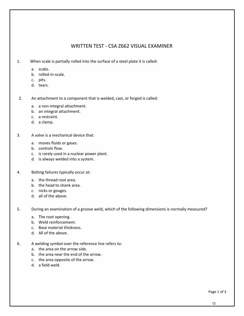
WRITTEN TEST - CSA Z662 VISUAL EXAMINER
1. When scale is partially rolled into the surface of a steel plate it is called:
a. scabs. b. rolled-in-scale. c. pits. d. tears.
2. An attachment to a component that is welded, cast, or forged is called:
a. a non-integral attachment. b. an integral attachment. c. a restraint. d. a clamp.
3. A valve is a mechanical device that:
a. moves fluids or gases. b. controls flow. c. is rarely used in a nuclear power plant. d. is always welded into a system.
4. Bolting failures typically occur at:
a. the thread root area. b. the head to shank area. c. nicks or gouges. d. all of the above.
5. During an examination of a groove weld, which of the following dimensions is normally measured?
a. The root opening. b. Weld reinforcement. c. Base material thickness. d. All of the above.
6. A welding symbol over the reference line refers to:
a. the area on the arrow side. b. the area near the end of the arrow. c. the area opposite of the arrow. d. a field weld.
Page 1 of 3
12

7. A device that raises, transfers, or pressurizes fluids by pressing, forcing, or throwing the fluid through apertures or pipes is called a: a. valve. b. pump. c. snubber d. bolt
8. Every inspector is affected differently by perception, fatigue, and attitude. In visual inspection, these factors are classified as: a. physiological factors. b. uncontrolled factors. c. production factors. d. classic distress factors.
9. During the visual examination of a full penetration double bevel weld joint, visual examination cannot locate:
a. undercut. b. underfill. c. crater cracks. d. Insufficient penetration.
10. Visual inspection is the most extensively used inspection method on weldments because:
a. it is simple and relatively inexpensive. b. it does not normally required special equipment. c. it gives important information about conformity to specifications. d. all of the above.
11. A groove formed at the toe or root of a weld when the base metal is melted away and left unfilled by weld
metal is referred to as: a. underfill. b. cold lap. c. crack. d. undercut.
12. A mechanical device that controls flow into, inside of, or out of a piping system is called a:
a. blind flange. b. pump. c. valve. d. flow controller.
13. In general, visual weld inspection is performed: a. before welding. b. during welding. c. after welding. d. all of the above.
13

Page 2 of 3
14. The welding process that is sometimes referred to as “stick welding” is: a. SAW. b. SMAW. c. GMAW d. GTAW.
15. In welding, temperature indicating sticks are used to monitor:
a. preheat temperatures. b. postheat temperatures. c. interpass temperatures. d. all of the above.
16. When visually examining an arc strike, the inspector should inspect for:
a. lack of fusion. b. craters. c. whiskers. d. cracks.
17. A nonfusion discontinuity that is located at the root area of a welded joint is called:
a. porosity b. a hot tear. c. incomplete joint penetration. d. all of the above.
18. Cracks can occur in:
a. forging. b. castings. c. welds. d. all of the above.
19. The heat-affected zone is the portion of the:
a. metal that is added to produce the weld joint. b. base metal that has been melted and solidified. c. base metal that has not been melted but where properties have been altered by the welding heat. d. original metal that is welded.
20. The visual inspector evaluating the welding process should consider the following factor(s):
a. preheat temperatures. b. filler metal control and handling. c. joint fit-up and bevel angle. d. all of the above.
Page 3 of 3
14
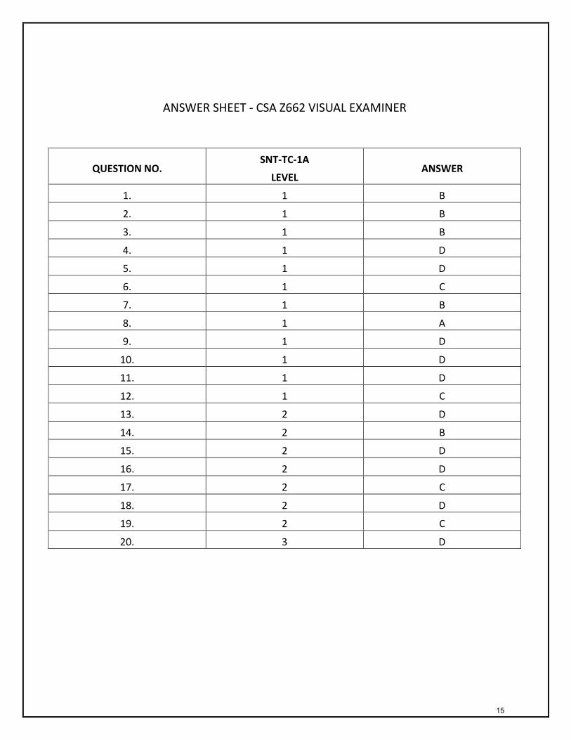
ANSWER SHEET - CSA Z662 VISUAL EXAMINER
QUESTION NO. SNT-TC-1A
LEVEL ANSWER
1. 1 B
2. 1 B
3. 1 B
4. 1 D
5. 1 D
6. 1 C
7. 1 B
8. 1 A
9. 1 D
10. 1 D
11. 1 D
12. 1 C
13. 2 D
14. 2 B
15. 2 D
16. 2 D
17. 2 C
18. 2 D
19. 2 C
20. 3 D
15

FORM #22-1 –LETTER OF APPOINTMENT AS A VISUAL EXAMINER
16

FORM #22-2 - REPAIR LIST FOR WELDS NOT MEETING VISUAL EXAMINATION REQUIRMENTS
Upon satisfactory completion of repairs sign-off Quality Form #1 to indicate acceptable visual weld quality.
17

18

19
20

21
22
23

24
25

26

27

28

29

30
31
32

33

34
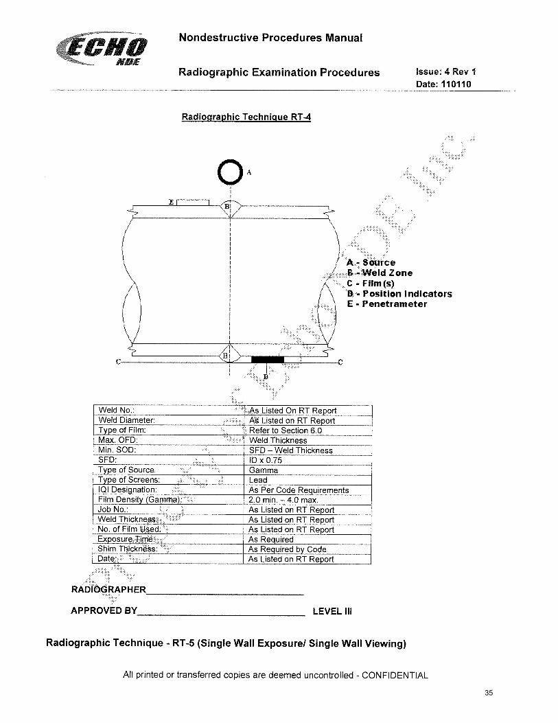
35

36

37

38
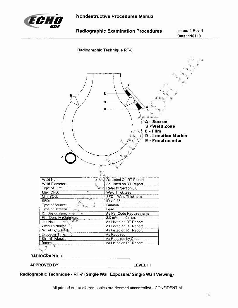
39

40
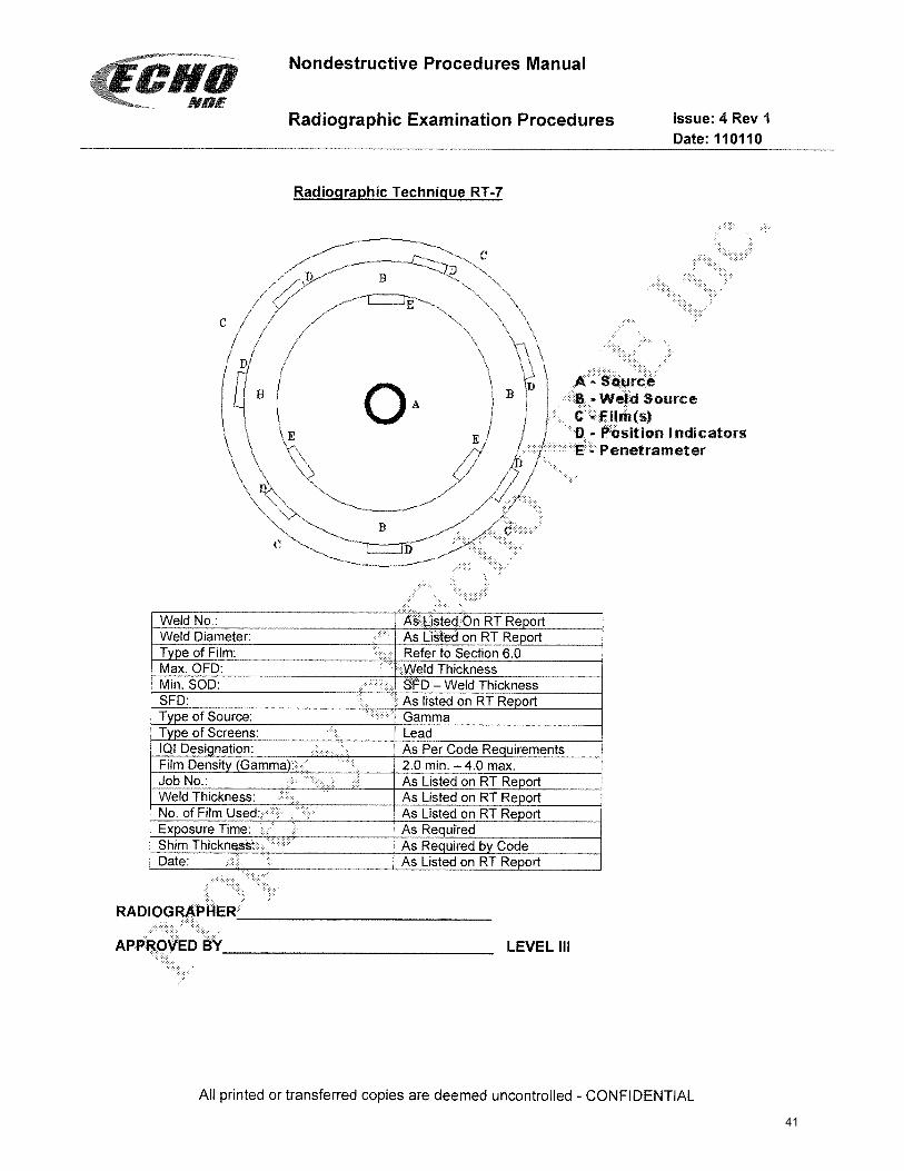
41

42

43
44
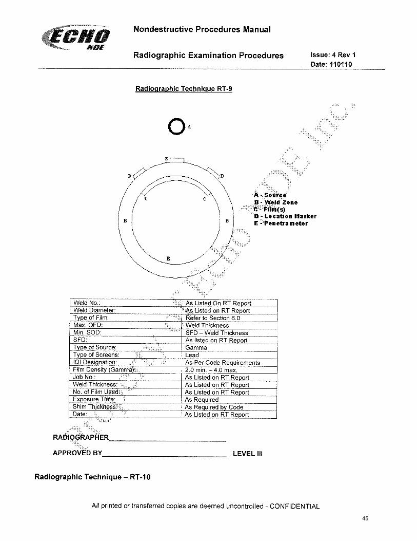
45

46
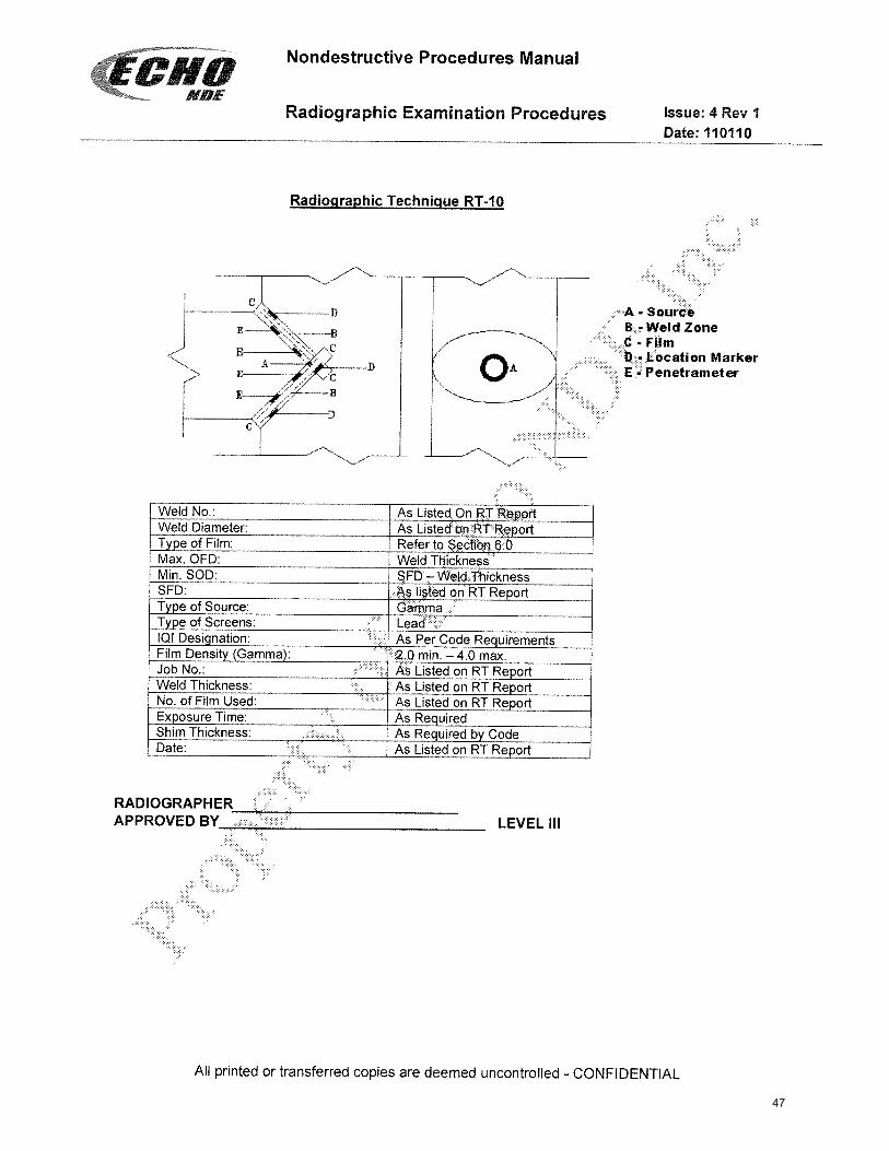
47
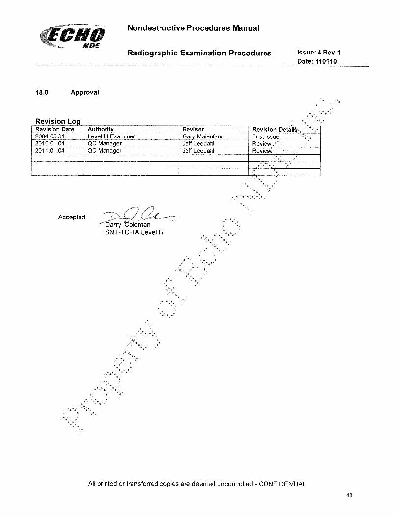
48