2.2 importance of subgrade on pavementsshodhganga.inflibnet.ac.in/bitstream/10603/8702/10/10_chapter...
TRANSCRIPT

7
CHAPTER 2
REVIEW OF LITERATURE
2.1 GENERAL
In this chapter a review of literature presented on importance of subgrade in pavement
design, swelling mechanism of expansive soils, subgrade treatment methods for
expansive and non expansive soils. The usage of geotextiles and geogrids in pavement
construction has also been discussed.
2.2 IMPORTANCE OF SUBGRADE ON PAVEMENTS
Coarse grained soils serve as good subgrades for supporting pavements where as fine
grained soils, particularly clayey soils pose problems to pavements (Yoder and Witczac,
1975).Pavement failure occurs due to two mechanisms, one is due to the combination of
densification and repetitive shear and the second is due to the deformation of pavement
component layers with more contribution from subgrade, particularly in clayey soils.

8
Generally flexible pavements are done using CBR method. The Rate of loading, size of
piston and compaction energy is certain limitations on CBR value (Yoder and Witczac,
1975). The subgrade soil at the edge regions of pavement is not properly reflected in
CBR test as the sample is not confined in vertical direction. The risk of shear of subgrade
soil is not considered in the methods group index, McLeod and AASHTO.
Similar to a shallow foundation, the soil-bearing capacity of the subgrade plays a large
role in supporting a road pavement and transferring the vehicle loads. It is necessary that
no shear failure occurs within the subgrade. In the method of plate-load testing Das
(2006) gave a field based test to check soil-bearing capacity. Satyanarayana Reddy and
Rama Moorthy (2005) reviewed existing flexible pavement building technology to
conclude that the safety against subgrade bearing capacity failure does not seem to be a
consideration in modern pavement design methods. Natarajan and Shanmakha Rao
(1979) and Steinberg (1985) report that the most apparent location of these failures
occurs in the extremity of pavements where moisture changes are common. The potential
that a particular subgrade and/or pavement material has for densification directly affects
the likelihood of permanent deformation occurring, which can be visible on the surface.
This deformation typically occurs along the wheel paths, and is worse in the outer path
(i.e. closer to the shoulder or kerb and channel).
The properties of subgrade soil are very importent in the design of flexible pavements
(Haas and Hudson, 1978). The subgrade influence is the main cause for pavement failure
and ruts in the flexible pavements (Reddy et. al. 1981; Saxena, 1989; Livenah & Ishai,
1987). The shear failure in subgrade soil is not properly accounted in the designing
methodology of pavements.
2.3 IMPACT OF EXPANSIVE SUBGRADE ON PAVEMENTS
The phenomenon of swelling soils in the country is recently being slowly recognized and
more often when this has manifested itself in the form of extensive damage to the
pavements. Swelling soils are widely distributed in areas of volcanic deposition or origin
with tropical climate and also in arid and/or semi desert climates. In tropical volcanic

9
settings, alumina rich volcanic ash gets deposited in general over a large area. Some get
concentrated in depressions or low areas which are fully saturated with water. This
regular inundation tends to leach the alumina and concentrate these at the bottom 1.0
meter to 2.0 meters generally and sometimes deeper depending on the leaching effects.
In expansive clayey subgrade due to cyclic shrinkage and swelling phenomenon there is
seasonal moisture fluctuation and more over they also loose strength due to softening
after swelling which might lead subgrade intrusion into overlying layers and penetration
of sub base material into it. (Holtz, 1959; Stevens et al, 1986; Deshpande et al, 1990;
Steinberg, 1985).
The damage caused by expansive soils to various civil engineering structures is
enormous due to their cyclic swell and shrink behaviour. Expansive soils have been
listed as one among the six major hazards (Earthquakes, Landslides, Expansive soils,
Hurricanes, Tornado and Floods) related to building losses from national hazards by
National Science Foundation in 1981 (Chen, 1988). Most of the civil engineering
structures built on expansive soils, highways and street roads receive major damage
which amounts to several thousand millions of dollars per annum (Jones and Holtz,
1973; Steinberg, 1992). The problems of roads in expansive clayey soils (black cotton
soils) is major as nearly 20 percent of area in India is covered by expansive soils and
carry several thousand kilometers of road length (Patel and Qureshi, 1979). The design
pavement thickness is high due to very low strengths of expansive soils in wet condition
and hence pavement construction becomes very costly (Sharma, 1988; Deshpande et al,
1990).
Apart from high initial cost of construction, pavements over expansive clay soil incur
high maintenance cost during and after every rainy season. Pavements over expansive
soil subgrades exhibit cracks due to alternate heave and settlement that lead to ultimate
failure of pavements (Sen and Chakraborthy, 1977). Swelling of expansive soil during
rainy season results in intrusion of subsoil into overlying structural layers of flexible
pavements and it is reported from Indian Roads Congress road test track project at
Peravali, A.P that even the stone soling, sand cushioning at subgrade level could not
check subgrade intrusion into overlying layers (Natarajan and Shanmukha Rao, 1979).
Further, the contamination of upper layers of pavements by subgrade soil reduces the

10
pavement thickness over a period of time that leads to progressive pavement failure
(Hicks et al, 1986). It is observed that a base contamination of 10 percent subgrade fines
can destroy structural strength of base layer.
The expansive soil subgrades soften after swelling and as a result rutting with
longitudinal cracks takes place along wheel tracks and lead to wavy appearance of
pavement surface (Gokhale, 1977; Agarwal and Saran, 1983; Livenah and Ishai, 1987;
Evans and Mc Manus, 1999). The longitudinal cracks later became source of moisture
entry into cross section of pavement and causes problem of raveling due to loss of bond
between aggregate and bitumen.
Noticeably major portion of road length over expansive soils in India is of single lane
and serious damages are found in rainy season due to off tracking of vehicles during
overtaking (Natarajan and Shanmukha Rao, 1979). As shoulders are not generally
designed for carrying loads, the subgrade soil is found to fail in shear at the shoulder and
edges. Even railway tracks supported on expansive soils are facing such failures (Ma-Ji,
1987).
2.4. SWELLING MECHANISM IN EXPANSIVE SOILS
The crystal structure of swelling clays (smectites) consists of one Al-OH (or Fe-OH or
Mg-OH) octahedral layer sandwiched by two Si-O tetrahedral layers .The deficiency in
positive charges of structural layers due to cation substitution, and interlayer cations are
required to balance the negative layer charge. Interlayer cations are exchangeable and
this exchange is reversible for simple cations.When the water molecules enter the space
between the structural layers, the distance between two structure layers increases and
volume of the clay expand. This is called clay swelling. The magnitude of swelling
depends on the nature (type) of the exchangeable cations, composition of the solution,
and the clay compositions. This is very severe in fresh water. The potential of clay
swelling decreases with increase in salinity. With salinity being the same, the potential of
clay swelling is largely influenced by the nature of the exchangeable cations. Among the
monovalent cations, swelling potential decreases in the order Li+<Na
+<K
++<Cs
+. Due to

11
this KCl and ammonium salts are often used in completion fluids. Generally smectites
with divalent cations swell less than those with monovalent cations.
2.5 METHODS OF SUBGRADE TREATMENT
Petry and Little (2002) believe that the majority of treatment methods currently used in
the field have been around since 1960, including various forms of chemical or
mechanical modification. The following methods are the popular treatment methods in
use.
2.5.1. Replacement
Das (2004) expresses that the first precaution of foundation construction on swelling
clays as replacement of the expansive soil with a less expansive material. This is an
interesting point since majority of researchers rates replacement as a last option. Ipswich
City Council has found this appears to be the case in established urban areas where
service pipes and conduits (such as telecommunications, water, sewerage, gas and oil)
are often within the roadway and under the pavements that needs reconstruction or
rehabilitation. However, current practice shows that if ample depth is available, the
preference is still to remove the weak clay soil and replace it with a less expansive
material (usually profiling from the old surface).
2.5.2 Controlled Compaction
West (1995) states that the bearing capacity of a subgrade soil can be improved by
densification or compaction of the soil. Consequently the soil displays a decreased
tendency to volume change (swell). Das (2006) states that if clay is compacted at less
than optimum, inter-particle repulsion is minimized and the double layer surrounding the
particle will be suppressed, leading to a random particle orientation. This clarifies that
the soil tends to swell as there is space for water molecules to occupy, however, a greater
strength is achieved than those soils compacted greater than OMC. When the soil is on
the wet side of optimum moisture content, the particles align producing less voids but a
slight reduction in strength. In addition to moisture, the degree of compaction effort
plays a major role in the final outcome.
Low compaction effort leads to greater compression when the moisture is slightly greater
than optimum. However, higher compaction effort requires moisture slightly below

12
OMC to achieve the same degree of compaction. In contrast to Das, Petry and Little
(2002) comment that during construction the moisture content should be maintained 3-
5% above the OMC till the final compaction.
2.5.3 Pre-wetting
Petry and Little (2002) state pre-wetting had become a proven method by the end of the
1970’s. McKinney, Kelly and McDowell (1974), Steinberg (1977) and Poor (1978)
believe that ponding water on a foundation reduces the future swell initial, often
controlled by moisture barrier installation. The idea of deliberately ponding water on the
subgrade before the construction of a pavement may seem a little unusual, however, Das
(2004) discusses the benefit of inducing heave. Water injection is yet another method of
achieving moisture stabilization of foundations/subgrades. A moistened soil can be
immediately covered with a plastic barrier to keep moist or constructed upon
immediately (Petry and Little 2002). The clear disadvantages of working on moist clays
include an inability to support the construction equipment and machinery and the process
can be time consuming. Das (2004) further commented on the option of lime
stabilization at this point to create a working platform.
2.5.4 Stabilization of Subgrade
Generally, there are three types of chemical stabilisers – traditional, by-product (kiln
dust) and non-traditional (such as sulphonated oils, polymers, enzymes etc). Petry and
Little (2002) make the comment that lime and portland cement are the most commonly
used chemical stabilizers, however, moisture stabilization (as previously described) is
still the most widely used method.
After conducting various tests Chen (1988) reported that among stabilizers including
calcium lime, portland cement and lime/cement mixtures, lime shows the greatest
improvement to compressibility, CBR and swelling. In the field it is extremely difficult
to properly mix the clay and lime due to natural moisture content. Eades, Nichols and
Grim (1963) gave the relationship between variable quantities of lime and different
mineral properties of clays. Still common today, lime quantities are being incorrectly
mentioned and as such many engineers do not consider the outcome effective. Harrison

13
(2005) after stdy of dynamic cone penetrometer (DCP) test results concluded lime
stabilisation improves the strength of black clay soils.
Ramanujam and Jones (2007) explain that the main disadvantage of subgrade cement
stabilization is the high stiffness and a tendency for the overlying pavement to crack.
Over recent years road makers have moved to an alternative slow setting cement that
contains additives in order to improve workability, however, this has proven to cause
greater stiffness than the original cement stabilization process leading to more cracking
problems. In Australia, Europe and the USA, alternative mixtures such as pozzolans have
gain popularity to enhance strength. Some clay types require special assistancse to
undergo the desired lime reaction.
Osinubi (2000) explains about the use of cement and pulversied coal bottom ash (PCBA)
as an admixture for stabilization of black clay in Nigeria. The reaction of the PCBA with
the clay produces cementing agents which produce an initial high strength followed by a
pozzolanic reaction leading to longer-term strength. PCBA is very similar to Portland
cement. For econimical solution Osinubi (2000) recommended 5% by weight of dry soil
pulverized PCBA mixed with 8% cement stabilised CL soil to improve subgrade soils.
Petry and Little (2002) recomended for future research, stabilisation should include the
establishment of protocols that allow the designer to determine the option best suited for
a particular scenario. In addition the issues of sulphate heave, understanding of the
mechanisms of stabilisation and assessment of various field properties from laboratory
results need to be refined.
2.5.5 Moisture Barriers
As the title here suggests, moisture barriers around a foundation or pavement can assist
in controlling the movement of water causing differential heave. This may include a
geosynthetic material or plastic layer that lines the pavement box to contain the
pavement materials. Of all the research carried out for this review, there was little
mention of the use of moisture barriers and no elaboration on successful methods.

14
2.5.6 Geosynthetics
Geosynthetics include a large variety of products composed of polymers and are
designed to enhance geotechnical and transportation projects. Geosynthetics perform at
least one of five functions: separation, reinforcement, filtration, drainage, and
containment.
Das (2006) believes that geosynthetics (including geofabrics, geotextiles, geomembranes
and the like) play a role in separation of materials, reinforcing, filtering, draining and
moisture barrier. By keeping a clay subgrade and sub-base material separate, increasing
load bearing capacity, protection of fine-grained soils from transportation and channeling
undesirable water away. This is supported by Zornberg and Gupta (2009) who state that
geosynthetics reinforce the subgrade or base materials by providing lateral restraint
(minimizing spread), tensile membrane support and increasing the bearing capacity.
Zornberg and Gupta (2009) conclude that in the absence of geofabric incorporation in
design manuals it appears that due to a lack of understanding and actual testing on the
contribution that these fabrics are delivering to improved pavement performance.
Tutumluer and Kwon (2005) gave cost benefit analyses have not yet been realised and an
adequate design procedure is unavailable.
In 2008, Zornberg et al. (2008) reported their findings after field evaluation of 35
projects over expansive clays in the USA (Forth Worth to Dallas) which were
experiencing cracking. They found that out of the 26 projects had been constructed using
geosynthetics (with bi-axial grids the preference) with no well defined design
procedures. Further investigations explained by Zornberg and Gupta (2009) proved to
have significant outcomes, as follows:
1. Geosynthetic reinforcement helps in preventing the development of longitudinal
cracks,where as the control section with no geogrid developed cracks within a few
months of construction.
2. Geosynthetic reinforcements will relocate cracks beyond the reinforced area,it was
reported that a trial section was not constructed as directed and the area in the road
shoulder where the geogrid did not cover cracked before the road was even opened to
traffic.
15
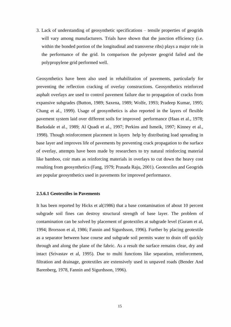
3. Lack of understanding of geosynthetic specifications – tensile properties of geogrids
will vary among manufacturers. Trials have shown that the junction efficiency (i.e.
within the bonded portion of the longitudinal and transverse ribs) plays a major role in
the performance of the grid. In comparison the polyester geogrid failed and the
polypropylene grid performed well.
Geosynthetics have been also used in rehabilitation of pavements, particularly for
preventing the reflection cracking of overlay constructions. Geosynthetics reinforced
asphalt overlays are used to control pavement failure due to propagation of cracks from
expansive subgrades (Button, 1989; Saxena, 1989; Wolfe, 1993; Pradeep Kumar, 1995;
Chang et al., 1999). Usage of geosynthetics is also reported in the layers of flexible
pavement system laid over different soils for improved performance (Haas et al., 1978;
Barksdale et al., 1989; Al Quadi et al., 1997; Perkins and Ismeik, 1997; Kinney et al.,
1998). Though reinforcement placement in layers help by distributing load spreading in
base layer and improves life of pavements by preventing crack propagation to the surface
of overlay, attempts have been made by researchers to try natural reinforcing material
like bamboo, coir mats as reinforcing materials in overlays to cut down the heavy cost
resulting from geosynthetics (Fang, 1979; Prasada Raju, 2001). Geotextiles and Geogrids
are popular geosynthetics used in pavements for improved performance.
2.5.6.1 Geotextiles in Pavements
It has been reported by Hicks et al(1986) that a base contamination of about 10 percent
subgrade soil fines can destroy structural strength of base layer. The problem of
contamination can be solved by placement of geotextiles at subgrade level (Guram et al,
1994; Brorsson et al, 1986; Fannin and Sigurdsson, 1996). Further by placing geotextile
as a separator between base course and subgrade soil permits water to drain off quickly
through and along the plane of the fabric. As a result the surface remains clear, dry and
intact (Srivastav et al, 1995). Due to multi functions like separation, reinforcement,
filtration and drainage, geotextiles are extensively used in unpaved roads (Bender And
Barenberg, 1978, Fannin and Sigurdsson, 1996).

16
The performance and service life can be improved by incorporating a geo textile in
pavement design (Guram et al., 1994). All roadways derive their strength and stability
from subgrade. The pavements loose their designed thickness over a period of time due
to intrusion of soft subgrade material into aggregate base and penetration of base
material into subgrade. When the pavement thickness is reduced, it leads to progressive
failure mechanism resulting in need for continuous road maintenance.
The reinforcing action of fabrics on unpaved road structure has been interpreted by
Hausmann, 1990 as follows:
By placing geotextiles over weak subgrades at subgrade level a general shear
failure takes place, where local or punching shear failure occurs otherwise. Thus
the bearing capacity factor of soil may be taken to increase from Nc = 3 to 5 or
more.
By placing geotextile at interface fabric restrains the aggregate base layer and
subgrade. The restrainment provided enables to account for load spreading by
considering slab action.
Subsidence associated with wheel path rutting develops tension in the fabric.
Reinforcing action of fabric within the subgrade is less because of necessary
displacement of soil prior to placement and low soil-fabric friction. Placement of
fabric at the interface of subgrade and sub base layer has the advantage of all
fabric functions.
Evaluation study on non-woven needle punched geotextile Supac 8NP (tensile strength
of 35 kN/m at elongation of 50%) with 610 mm of lime stabilised subgrade was carried
out on state highway SH-131 in Atoka county, Oklahoma (Guram et al., 1994). It has
been reported that non-woven geotextile showed performance equivalent to that of lime
treated layer. Even after 9 years the fabric did not loose any strength.Significant savings
in both construction and maintenance are realised due to placement of geotextiles.

17
USDA forest service (Powell and Mohney, 1994) used geotextiles in the year 1976 in
test sections of flexible pavements over subgrade soils of high organic clays and silts
with CBR values less than 1. The tensile strengths of fabrics used were 10 kN/m and 20
kN/m. The fabrics were laid at subgrade level and 0.5 to1m thick shot rock fill was
dumped. The rock fill was surfaced by 0.2 to 0.3m of glacial pit run gravels. The
constructed pavement is tested to 36000 kg gross vehicle load. Geotextiles are found to
function as per the design. It is found that tensile strength decreased by about 10 to 40%
owing to construction damage and there after during service the strength loss was only 2
to 12%. It is also reported that stresses from traffic did not cause damage to the
geotextiles.
Cancelli et al. (1992) showed that a woven, flexible geogrid and a high-modulus
geotextile- reinforced section performed marginally better than the control section, where
as stiff geogrids and a multilayer geogrid have proved significant improvement. For very
soft subgrades, two layers of a relatively weak geogrid were found to be more effective
than placing one layer of a very stiff geogrid. Geogrids were effective in allowing for
reduced base course layer thicknesses and in extending the service life of a section for a
given thickness. Geogrid benefits generally increases with decrease in subgrade strength
and increase in allowable rut .
Killeavy and Anderson (1989) tested three sections with different base course
thicknesses that were designed to perform identically. The results of the study indicate
that all the sections performed the same. Therefore, the geotextile – reinforced base
layer thickness could be reduced from450 to 350 mm, while the geogrid- and geotextile-
reinforced section thickness could be reduced from 450 to 200 mm.
Public works department in Maharashtra state used non-woven geotextiles and bi-
oriented geogrids in the state high ways for strengthening the pavements over black
cotton soils in 1997 (Rao and Banerjee, 1999). Based on limited Indian experiences,
Ministry of Surface Transport (Roads wing) has included geosynthetics for use in
subsurface drains, highway pavements, slope protection works and reinforced soil
structures in their 1995 version of specifications for road and bridge work.
18
Of the design approaches proposed, the empirical methods of Penner et al. (1985),
Montanelli et al. (1997), and Webster (1992) are limited to the experimental study. The
design methods do not appear capable of accounting for the influence of wide variations
in variables such as geosynthetic type, load magnitude, asphalt concrete and base layer
thickness, and subgrade type. The analytical method proposed by Davies and Bridle
(1990) does not account for movement in the base layer soil, which appears to largely
control the development of rut depth for properly designed sections and must be
calibrated from actual pavement loading experiments.
The analytical approach of Sellmeijer (1990) appears promising due to its ability to
account for the effect of increased confinement on the base course layer as a result of
interaction with the geosynthetic .Varying degrees of success have been reported in
developing a finite element model to predict the response of reinforced flexible
pavements. Barksdale et al. (1989) and Miura et al. (1990) incorporated certain
laboratory/field tests into their design models. Perhaps the most significant limitation of
all of the models developed to date is the inability to predict pavement section response
over a number of repeated load cycles. All of the models were developed to predict
response of pavement under a single load application.
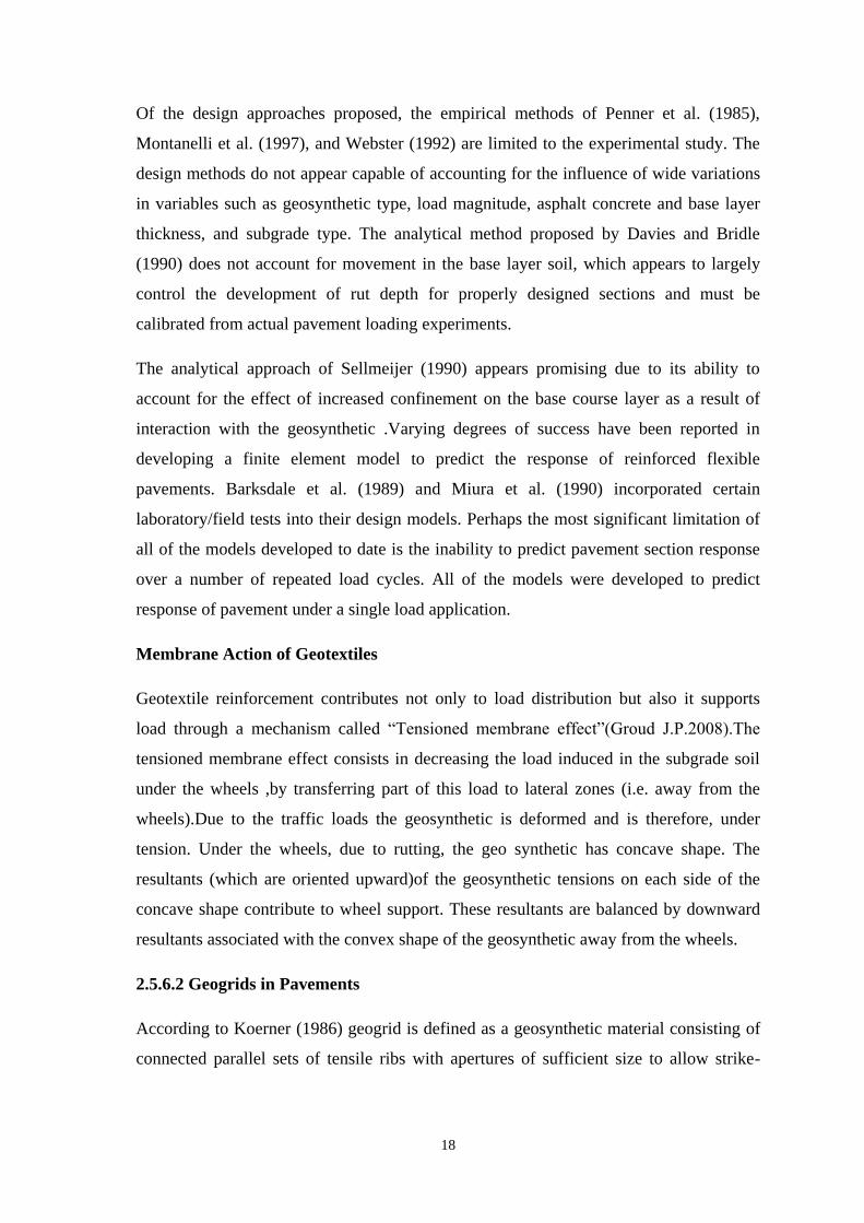
Membrane Action of Geotextiles
Geotextile reinforcement contributes not only to load distribution but also it supports
load through a mechanism called “Tensioned membrane effect”(Groud J.P.2008).The
tensioned membrane effect consists in decreasing the load induced in the subgrade soil
under the wheels ,by transferring part of this load to lateral zones (i.e. away from the
wheels).Due to the traffic loads the geosynthetic is deformed and is therefore, under
tension. Under the wheels, due to rutting, the geo synthetic has concave shape. The
resultants (which are oriented upward)of the geosynthetic tensions on each side of the
concave shape contribute to wheel support. These resultants are balanced by downward
resultants associated with the convex shape of the geosynthetic away from the wheels.
2.5.6.2 Geogrids in Pavements
According to Koerner (1986) geogrid is defined as a geosynthetic material consisting of
connected parallel sets of tensile ribs with apertures of sufficient size to allow strike-

19
through of surrounding soil, stone, or other geotechnical material.Existing commercial
geogrid products include extruded geogrid (Geogrid – Tenax LBO 330 SAMP) ,woven
geogrids, welded geogrids, and geogrid composites. Most geogrids are made of
polymers, but some products have been manufactured from natural fibres, glass, and
metal strips.
Geogrids used within a pavement system perform the primary functions of geosynthetics:
separation and reinforcement. Due to their large aperture size associated with geogrids
are typically not used for achieving separation of dissimilar materials. The ability of a
geogrid to separate two materials is a function of the gradations of the two materials and
is generally outside the specifications for typical pavement materials. However, geogrids
can theoretically provide some measure of separation, but limited. For this reason,
separation is a secondary function of geogrids used in pavements. The primary function
of geogrids used in pavements is reinforcement, in which the geogrid mechanically
improves the engineering properties of the pavement system.
The three primary uses of a geogrid in a pavement system are to serve as a construction
aid over weak subgrades, to improve or extend the pavement’s projected service life and
to reduce the structural cross section for a given service life. Geogrids have been
successfully used to provide a construction platform over weak subgrades (Cancelli et al.
1996, Haas et al. 1978, Halliday and Potter 1984, and Santoni et al. 2001). In this
application, the geogrid improves the ability to obtain compaction in overlying
aggregates, while reducing the amount of material required is to be removed and
replaced. Numerous research programs have also reported the extended service lives for
pavement sections with geogrids compared to similar sections without geogrids (Al-Qadi
et al. 1997, Barksdale et al. 1989, Cancelli et al. 1996, Collin et al. 1996, Haas et al.
1988, Miuraet al. 1990, Perkins et al. 1997a/b, and Webster 1993). Finally, research has
shown that the required base course thickness for a given design may be reduced by
using geogrid in pavements.
For mechanical subgrade stabilization and base reinforcement applications the geogrid
should be placed at the bottom of the base for aggregate layers less than 14 inches. If a
geotextile is to be used for separation of the subgrade and base materials, the geotextile
should be placed directly on the top of the subgrade. The reinforcement geogrid is then
placed directly on top of the separation geotextile for aggregate layers less than 14
inches. For pavements with a design base thickness greater than or equal to 14 inches,

20
the geogrid should be placed in the middle of the base course layer (Webster 1993).
However, Collin et al. (1996) and Haas et al. (1988) recommend to place the geogrid in
the middle of the base course layer for layers more than 10 inches, otherwise placement
should occur at the layer interface. Regardless of the placement location of the geogrid,
the separation geotextile is always placed at the subgrade base interface.
Tests by Watts et al. (1996) interpreted by Giroud & Han (2006) show that geogrid
strains under dual wheels are still very small (i.e. between 0.1 and 1.2%) after full
development of ruts at the end of the test. Like other geosynthetic fabrics used in any
application, a geogrid is sufficiently robust to withstand the rigors of transportation,
handling, installation, placement of materials in contact, and other construction activities.
Also, the geogrid is capable of maintaining the integrity of its structure and properties
throughout its service life. The geogrid material is not degradable for long periods in any
way in a soil environment.
Al-Qadi et al. (1997) and Smith et al. (2004) after studying three test track concluded
that the improvement mechanisms associated with geogrids and geotextiles were
different. Mixing of the subgrade and base course material was observed in the control
and geogrid-reinforced sections, where as contamination was not observed in the
geotextile-reinforced sections.
Killeavy M and Anderson (1989) performed FWD tests on field test sections that were
designed to yield equivalent performance. The test results indicated that similar subgrade
deformations were observed in each section, and reduced asphalt strain and better load
distribution occurred in the geogrid-reinforced sections. Back-calculation techniques
showed that the geogrid section had the largest base layer modulus (560 MPa), followed
by the geotextile section (400 MPa) and the control section (170 MPa). Visual
observation of the sections after a one year and a ten year monitoring period indicated
little difference between the surface rut characteristics of the three sections. Barker
(1987) compared a test section reinforced with Geogrid, where the reinforcement was
placed in the middle of the 150 mm thick base, to an identical unreinforced test section.
In terms of rut depth development, the reinforced section performed worse than the
control section for rut depths less than 18 mm. For instance, for 10 traffic passes, the
reinforced section showed 4 mm of displacement while the control section showed less
than 1 mm. For rut depths greater than 18 mm, the performance of the reinforced section,
as compared to the control section, continued to increase.
21
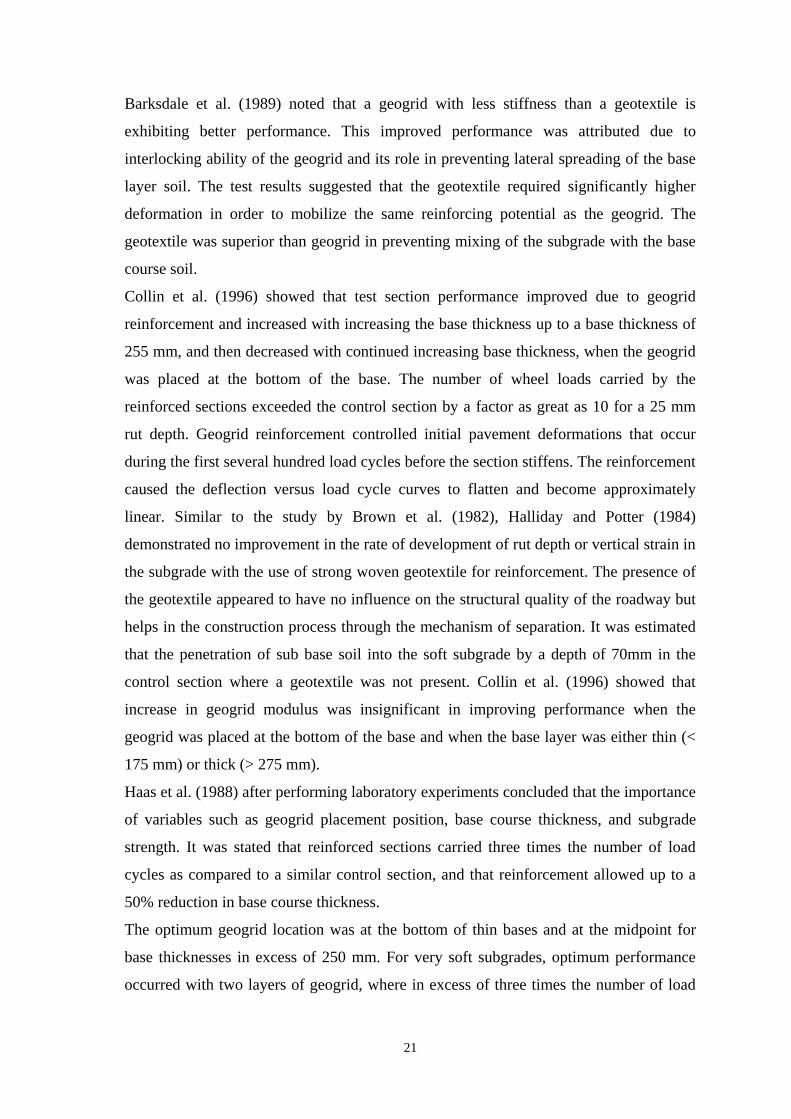
Barksdale et al. (1989) noted that a geogrid with less stiffness than a geotextile is
exhibiting better performance. This improved performance was attributed due to
interlocking ability of the geogrid and its role in preventing lateral spreading of the base
layer soil. The test results suggested that the geotextile required significantly higher
deformation in order to mobilize the same reinforcing potential as the geogrid. The
geotextile was superior than geogrid in preventing mixing of the subgrade with the base
course soil.
Collin et al. (1996) showed that test section performance improved due to geogrid
reinforcement and increased with increasing the base thickness up to a base thickness of
255 mm, and then decreased with continued increasing base thickness, when the geogrid
was placed at the bottom of the base. The number of wheel loads carried by the
reinforced sections exceeded the control section by a factor as great as 10 for a 25 mm
rut depth. Geogrid reinforcement controlled initial pavement deformations that occur
during the first several hundred load cycles before the section stiffens. The reinforcement
caused the deflection versus load cycle curves to flatten and become approximately
linear. Similar to the study by Brown et al. (1982), Halliday and Potter (1984)
demonstrated no improvement in the rate of development of rut depth or vertical strain in
the subgrade with the use of strong woven geotextile for reinforcement. The presence of
the geotextile appeared to have no influence on the structural quality of the roadway but
helps in the construction process through the mechanism of separation. It was estimated
that the penetration of sub base soil into the soft subgrade by a depth of 70mm in the
control section where a geotextile was not present. Collin et al. (1996) showed that
increase in geogrid modulus was insignificant in improving performance when the
geogrid was placed at the bottom of the base and when the base layer was either thin (<
175 mm) or thick (> 275 mm).
Haas et al. (1988) after performing laboratory experiments concluded that the importance
of variables such as geogrid placement position, base course thickness, and subgrade
strength. It was stated that reinforced sections carried three times the number of load
cycles as compared to a similar control section, and that reinforcement allowed up to a
50% reduction in base course thickness.
The optimum geogrid location was at the bottom of thin bases and at the midpoint for
base thicknesses in excess of 250 mm. For very soft subgrades, optimum performance
occurred with two layers of geogrid, where in excess of three times the number of load

22
cycles could be carried. Strain measurements on the geogrid showed that tensile strains
in excess of 1% was observed under the load center and that these strains diminish to
zero at a radius of 1.5 times the radius of the load plate, indicating that long anchorage
lengths were not required in such situations.
The laboratory test results reported by Miura et al. (1990) demonstrated that geogrids of
increased stiffness provided for improved performence. Improvement was closely related
to the magnitude of strain measured in the geogrid while loading. The performance of the
field sections also improved by using the stiff geogrids, but not to the same level as that
demonstrated in the laboratory tests.
Tensile properties of geogrids can vary among manufacturers. Trials have shown that the
junction efficiency (i.e. within the bonded portion of the longitudinal and transverse ribs)
plays a major role in the performance of the grid. In this case the polyester geogrid failed
and the polypropylene grid performed well. Moghaddas-Nejad and Small (1996)
demonstrated that placing of geogrid at the bottom of a thin base results in a 40%
decrease in rut depth for single-track wheel passes and a relatively light load, whereas
geogrid placement in the middle of the base results in a 70% decrease. These values
correspond to 5000 wheel passes. For multiple-track loading, both placement positions
resulted in a 50% decrease in rut depth. The deflection basins below the reinforced
sections were wider and shallower than those of the unreinforced section, suggesting that
the reinforcement improved the pressure distribution on the subgrade. Studies on
measurements of vertical deformation at the level of the geogrid showed that there was
substantial improvement when load-induced vertical deformations of the geogrid were
less than several millimeters. This suggests that improved performance was not due to a
tensioned membrane effect, but was due to lateral restraint of the base soil.
Webster (1993) showed that flexible geogrids were not as effective as stiff geogrids for
base layer reinforcement in flexible pavements. The torsional rigidity of the geogrid,
which is governed in part by the characteristics of the junctions, was the most important
factor to determine the suitability of the geogrid product. Sections reinforced with a stiff
geogrid are efficient in carrying as much as 21 times the number of traffic loads as an
unreinforced section. The value of this factor depended on the position of placing the
geogrid, the thickness of the base layer, and the strength of the subgrade soil.
Barker (1987) tested by constructing a one-layer, reinforced test section containing a
geogrid placed in the middle of a 150 mm thick base resting on a strong sub base-

23
subgrade system. The traffic load applied to the section was heavy in comparison to the
majority of the other studies. The reinforced section performed worse than the control
section up to a 18 mm rut depth; for greater rut depths improvement was observed.
2.6. REVIEW OF DESIGN PRACTICES OF REINFORCED FLEXIBLE
PAVEMENT
To determine the aggregate pavement thickness a number of design procedures has been
proposed by Giroud & noiray, Sellmeijer et al..,Koerner and Barenberg etc. Among these
Giroud& Noiry and BarenBerg are popular.
2.6.1 Giroud and Noiray Method
They proposed a design methodology taking into consideration the membrane effect of
geotextile and allowance to traffic. In his analysis he equated the maximum pressure on
subgrade to ultimate bearing capacity. The pressure on subgrade is given by,
qu = P - Pg --- (1)
where,
qu is ultimate bearing capacity of subgrade soil = 5.14 Cu + h
P = pressure on subgrade due to surcharge
Pg = Reduction of pressure due to membrane effect
Pressure P is calculated using load spread angle through aggregate layer as
H
hTanLhTanB
PP
222 --- (2)
Where, P is the Axle load
is unit weight of aggregate
Dual wheels are assumed with each set of tires covering an area BxL. For a tyre pressure
pc, the dimensions are as follows.
On Highway Trucks Off Highway Trucks

24
cp
PB
cp
PB
2
2
BL
2
BL
The methodology uses a value of =0.6 in reinforced case conservatively that exists in
unreinforced case.
The Pg value is determined by assuring that the shape of deformed geotextiles represents
a section of parabolas and the volume of central heaved area is related to soil displaced
by settlement. The fabric strain is calculated as
1'
'
aa
bb for a' a
= 1a
b for a a'
Where, b and b' represent the half chord lengths of parabolas p and p'
The widths a and a' are obtained from the relationships.
2a = B + 2h Tan
2a' = e – B – 2h Tan
Where, ‘e’ is track width.
Chord lengths b and b' are calculated from the following equations
2
21
2ln
2
21
2
11
22
a
s
a
s
s
a
a
s
a
b
2
21
2ln
2
21
2
11
2
''
'2
''
'
a
sr
a
sr
sr
a
a
sr
a
b
Finally the fabric tension is determined from the relation,
T = Ef
and membrane support as,

25
Pg = 2
21
s
aa
EP
f
g
where, Ef is elastic modulus of the fabric.
Figure 2.1 Shape of Deformed Fabric According to Giroud and Noiray
Using equation 1 for the cohesion Cu, a relationship can be established between Cu and
required aggregate height for a given geometry, load, configuration and fabric modulus.
The analysis is referred to as quasi-static as it does not take into account traffic numbers.
The effect of traffic is considered to impose the same effect on reinforced pavements
with regard to increase in design pavement thickness. The unreinforced aggregate depth ,
ho is given by
63.0
'
0
8887.117892.3log3964.6log6193.1
uC
rPNh
N20 & N 10,000
where P = axle load
Cu = 30 CBR (kPa)
r = rut depth (m)
Initial location of Geotextile
2
a
2
a
2a’
e
r s s Geotextile

26
for N 20, it is proposed to use a quasi-static analysis based on a bearing failure, at qu =
Cu + h0' and the pressure at the aggregate-subgrade interface can be calculated
according to equation 2 with h0 instead of h.
The theory does not account for the velocity of vehicles, loads and suits only to unpaved
roads. The design methodology is based on a total vertical stress of qu at subgrade level,
which leads to higher settlements in soft clays. So the theory should not be used in paved
roads where surface settlement should not exceed 40mm or less.
2.6.2 Koerner Method
Koerner proposed a laboratory method modeling the field situation to arrive at the
influence of a geotextile (Koerner, 1986). The method involves conducting CBR test on
CBR specimen with soil and aggregates half filled. The test is to be done up to 5 cm
penetration level. CBR test is also done on specimen with geotextile held in position at
interface of soil and aggregate. The reinforcement ratios, defined as load resisted by
unreinforced and unreinforced specimen are calculated at different penetration levels.
Modified CBR value is determined as Maximum reinforcement ratio x actual CBR value
of soil. The design thickness of reinforced flexible pavement is determined using
modified US army Corps of Engineers Formula given below.
5.0
45.66045.3305.0log447.0
A
CBR
Pct
where,
t = Thickness of pavement in cm
c = Anticipated number of vehicle passes
P= ESWL in kg
A = Contact area of tyres in cm2
However, the design is based on small scale load penetration test and needs verification
in the field.
Geotextile fabrics were suggested to be used over soft clay subgrades based on analytical
report to economise pavement thickness and reduce rutting (Natarajan et al., 1989). The
fabric deformed shape at subgrade has been treated as combination of two inclined
27
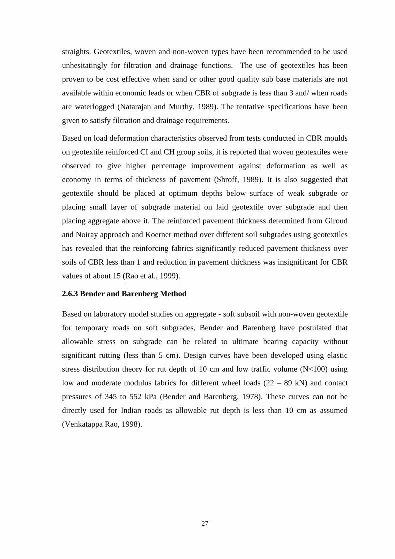
straights. Geotextiles, woven and non-woven types have been recommended to be used
unhesitatingly for filtration and drainage functions. The use of geotextiles has been
proven to be cost effective when sand or other good quality sub base materials are not
available within economic leads or when CBR of subgrade is less than 3 and/ when roads
are waterlogged (Natarajan and Murthy, 1989). The tentative specifications have been
given to satisfy filtration and drainage requirements.
Based on load deformation characteristics observed from tests conducted in CBR moulds
on geotextile reinforced CI and CH group soils, it is reported that woven geotextiles were
observed to give higher percentage improvement against deformation as well as
economy in terms of thickness of pavement (Shroff, 1989). It is also suggested that
geotextile should be placed at optimum depths below surface of weak subgrade or
placing small layer of subgrade material on laid geotextile over subgrade and then
placing aggregate above it. The reinforced pavement thickness determined from Giroud
and Noiray approach and Koerner method over different soil subgrades using geotextiles
has revealed that the reinforcing fabrics significantly reduced pavement thickness over
soils of CBR less than 1 and reduction in pavement thickness was insignificant for CBR
values of about 15 (Rao et al., 1999).
2.6.3 Bender and Barenberg Method
Based on laboratory model studies on aggregate - soft subsoil with non-woven geotextile
for temporary roads on soft subgrades, Bender and Barenberg have postulated that
allowable stress on subgrade can be related to ultimate bearing capacity without
significant rutting (less than 5 cm). Design curves have been developed using elastic
stress distribution theory for rut depth of 10 cm and low traffic volume (N<100) using
low and moderate modulus fabrics for different wheel loads (22 – 89 kN) and contact
pressures of 345 to 552 kPa (Bender and Barenberg, 1978). These curves can not be
directly used for Indian roads as allowable rut depth is less than 10 cm as assumed
(Venkatappa Rao, 1998).

28
2.7 DEFICIENCIES IN THE EXISTING LITERATURE
The following deficiencies have been noticed from the literature that has been reviewed
above.
There is no established procedure for design of reinforced flexible pavement over
clay subgrade in general and expansive soil in particular.
The concept of membrane action of geotextile reinforcement and geo grid
reinforcement over soft subgrade requires further study.
Usage of geotextile for swell control was not given much attention.
None of the papers reported reinforced mattress approach of geogrids.
Less work was done on performance study of laid test tracks with geosynthetic
reinforcement in expansive soils.
2.8 SPECIFIC SCOPE OF THE PROPOSED RESEARCH
In the present work, a design methodology was formulated for reinforced flexible
pavement design over non expansive and expansive clay subgrades ensuring safety
against swell, shear failure and settlement failure risks.
The performance of CH soil in CBR method is compared and a reinforced method
through test track studies is proposed.
The reinforced soil mattress concept applied to stiffen the sub base layer using
geogrid reinforcement in flexible pavement design over a clay subgrade of
intermediate compressibility is also studied.
The test track is laid using geogrid and is being monitored under traffic and varied
seasonal effects.
2.9 SUMMARY
In literature review existing practices for design of reinforced flexible pavement and
deficiencies are noticed. After defining specific scope from literature review the research
methodology has been developed and presented in next chapter.