215 roadside safety - florida department of transportation · the aashto roadside design guide...
TRANSCRIPT

Topic #625-000-002 FDOT Design Manual
215-Roadside Safety
215 Roadside Safety
215.1 General
This Chapter contains roadside safety design criteria for new construction, reconstruction, and Resurfacing, Restoration and Rehabilitation (RRR) projects. New Construction criteria must be met for new and reconstruction projects, and for improvements included with RRR projects.
The design criteria contained in FDM 210 and FDM 211 has been developed to minimize the probability that a vehicle will depart the roadway. Design elements that affect roadside safety include: horizontal alignment, superelevation, vertical alignment, drainage design, sight distance, lane widths, pavement, pavement markings, cross slopes, median widths, shoulders, and lighting.
The evaluation of Roadside Safety design elements is necessary to address the occasional errant vehicle that does depart the roadway. These design elements include roadside geometries, lateral offsets to potential hazards, and the use of shielding.
The AASHTO Roadside Design Guide (AASHTO RDG) provides the foundation for the development of specific criteria contained in this Chapter and the Standard Plans.
215.1.1 RRR Criteria
Criteria for RRR projects provided in this chapter are the minimum values allowed for roadside elements to remain on arterials and collectors without obtaining a Design Exception or Design Variation (see FDM 122).
Criteria for RRR projects provided in this chapter may be used for establishing the minimum requirements for adding auxiliary lanes, keyhole lanes, or providing minor intersection improvements with the understanding that when existing right of way (R/W) is adequate, new construction criteria will be used to the maximum extent feasible.
Do not apply RRR criteria in this chapter to resurfacing projects on Limited Access (LA)Facilities.
1
January 1, 2018

Topic #625-000-002 FDOT Design Manual
215-Roadside Safety
215.2 Roadside Features
215.2.1 Roadside Geometry
Roadside geometry refers to the terrain features (slopes) that a vehicle will encounter when departing a roadway. The components of roadside geometry include front slopes, back slopes, and transverse slopes.
215.2.2 Roadside Slope Classification
Roadside Slopes include areas located beyond the edge of the traffic lane as shown in Figures 215.2.2 and 215.2.3. These areas are divided into the following classifications:
(1) Traversable Slope – Smooth terrain, unobstructed by fixed objects: (a) Recoverable Traversable Slope, 1:4 or flatter (b) Non-Recoverable Traversable Slope, steeper than 1:4 and flatter than 1:3
(2) Non-Traversable Slope – Rough terrain, obstructed, or slopes steeper than 1:3
215.2.3 Clear Zone Criteria
Providing a sufficient amount of Recoverable Slope adjacent to the roadway provides an opportunity for an errant vehicle to safely recover. The amount of recoverable area provided beyond the traveled way is defined as the clear zone, and includes shoulders and bike lanes. The clear zone must be free of roadside hazards, as defined in FDM 215.3.
Traversable Back Slopes 1:3 or flatter may be located within the clear zone.
A clear zone width must be provided so that the sum of all Recoverable Slopes is equal to or greater than the required clear zone width obtained from Table 215.2.1. Clear zone widths may be widened based on crash history and horizontal curvature; see AASHTO RDG, Section 3.1. Clear zone concepts are illustrated in Figure 215.2.1 and Figure 215.2.2. For Roadside Slope Criteria, see FDM 215.2.6.
2
January 1, 2018

Topic #625-000-002 FDOT Design Manual
215-Roadside Safety
Figure 215.2.1 Clear Zone Plan View
Figure 215.2.2 Clear Zone Concept
When a Traversable Non-Recoverable Slope is present within the clear zone, extend the clear zone width until the amount of Recoverable Slope equals the required clear zone width obtained from Table 215.2.1. The additional width provided beyond the Traversable Non-Recoverable Slope is known as the Clear Run-out Area and is illustrated in Figure 215.2.3. The Clear Run-out Area should be a minimum of 10 feet wide when R/W is adequate.
3
January 1, 2018

Topic #625-000-002 FDOT Design Manual
215-Roadside Safety
Figure 215.2.3 Adjusted Clear Zone Concept
Table 215.2.1 Clear Zone Width Requirements
Design Speed (mph)
≤ 30 35 40 45 50 55 ≥ 60
Clear Zone Width for New Construction
Travel Lanes & Multilane Ramps 12 feet 14 feet 18 feet 24 feet 24 feet 30 feet 36 feet
Auxiliary Lanes & Single Lane Ramps 10 feet 10 feet 10 feet 14 feet 14 feet 18 feet 24 feet
Clear Zone Width for RRR Projects
Travel Lanes & Multilane Ramps 6 feet 6 feet 6 feet 14 feet 18 feet 18 feet 18 feet
Auxiliary Lanes & Single Lane Ramps 6 feet 6 feet 6 feet 8 feet 8 feet 8 feet 8 feet
Clear zone widths for work zones are provided in Standard Plans, Index 102-600.

Topic #625-000-002 FDOT Design Manual
215-Roadside Safety
215.2.4 Lateral Offset
Lateral offset is the distance from a specified point on the roadway to a roadside hazard. Lateral offset to the roadside hazard is measured as follows:
Curbed roadways: from face of curb.
Flush shoulder and high-speed curbed roadways: from outside edge of traveledway.
Lateral offsets apply to all roadways and are determined based on the following:
Type of facility; i.e., flush shoulder or curbed roadway,
Design speed
Design Element
Project Type; i.e. New Construction, RRR
Flush shoulder roadways typically have sufficient R/W, to provide the required clear zone widths. Therefore, minimum lateral offset for these roadways is based on maintaining a clear roadside for errant vehicles to recover (i.e., maintaining clear zone width provided in Table 215.2.1).
Lateral offsets for curbed roadways should be based on clear zone criteria; however, curbed roadways typically do not have sufficient R/W to provide the required clear zone widths. Therefore, minimum lateral offset on these roadways is based on offset needed for normal operation of the roadway.
At times it may be necessary to place poles (e.g., signal, light, sign) within the sidewalk. Refer to FDM 222.2 for minimum unobstructed sidewalk width requirements.
Table 215.2.2 provides minimum lateral offset criteria for roadside features and roadside hazards typically encountered and considered functionally necessary for normal operation of the roadway; e.g., signing, lighting, utilities. For crashworthy objects, meet or exceed the minimum lateral offset criteria provided in Table 215.2.2. Locate objects that are not crashworthy as close to the R/W line as practical and no closer than the minimum lateral offset criteria provided.
When a roadside hazard is placed behind a barrier that is justified for other reasons, the minimum lateral offset to the object equals the setback requirements (deflection distance) of the barrier, see FDM 215.4.6. Refer to FDM 215.5 for permissible attachments to barriers.
5
January 1, 2018

Topic #625-000-002 FDOT Design Manual
215-Roadside Safety
When determining minimum lateral offset for bridge piers and abutments, coordinate with vertical clearance requirements found in FDM 210.10.3. When shielding is used, refer to setbacks to barriers in FDM 215.4.6 and FDM 210.10.3.
6
January 1, 2018

Topic #625-000-002 FDOT Design Manual
215-Roadside Safety
Table 215.2.2 Minimum Lateral Offset Criteria
Design Element
Curbed Roadways
High Speed Curbed and Flush Shoulder Roadway
New Construction RRR
Design Speed
25-35 mph
40-45 mph
25-35 mph
40-45 mph
Light Poles Conventional
Do not locate in Medians, except in conjunction with barriers that are justified for other reasons. See FDM 215.2.9.
1.5 feet 4.0 feet 1.5 feet 1.5 feet
20 feet from Travel Lane, 14 feet from Auxiliary Lane, or
Clear Zone width, whichever is less
High Mast Outside Clear Zone
Signal Poles and Controller Cabinets
Do not locate in Medians. See FDM 215.2.9.
1.5 feet 4.0 feet 1.5 feet 1.5 feet Outside Clear Zone
Traffic Infraction Detectors For placement and installation specifications, refer to the State Traffic
Engineering and Operations Office web page: http://www.fdot.gov/traffic/
ITS Poles and Related Items
Pole & Other Aboveground Fixed Objects
Do not locate in Medians, except in conjunction with barriers that are justified for other reasons. See FDM 215.2.9.
1.5 feet 4.0 feet 1.5 feet 4.0 feet Outside Clear Zone
Equipment Shelters and
Towers
Do not locate within the limited-access right of way, except as allowed by Policy No. 000-625-025, Telecommunications Facilities on Limited
Access Rights of Way. Breakaway
Objects 1.5 feet 4.0 feet 1.5 feet 4.0 feet As Close to R/W As Possible
Traffic Control Signs
Single and Multi-Column Locate in accordance with Standard Plans.
Overhead Sign
Structures Outside Clear Zone
Trees
Where the diameter is or is expected to be > 4 inches measured 6
inches above the ground
1.5 feet 4.0 feet 1.5 feet 1.5 feet Outside Clear Zone
RRR Projects: (1) Meet New Construction criteria for new plantings.
7
January 1, 2018

Topic #625-000-002 FDOT Design Manual
215-Roadside Safety
Table 215.2.2 Minimum Lateral Offset Criteria (cont.)
Design Element
Curbed Roadways
High Speed Curbed and Flush Shoulder Roadway
New Construction RRR
Design Speed
25-35 mph
40-45 mph
25-35 mph
40-45 mph
Aboveground Utilities
(See FDM 215.2.8)
Existing Utilities 1.5 feet 4.0 feet 1.5 feet 4.0 feet Outside Clear Zone
New or Relocated
Utilities 4.0 feet Outside Clear Zone
RRR Projects: Existing aboveground utilities are not required to be relocated unless one of the following
applies: The edge of traveled way is being moved closer to the aboveground utility; e.g.,
addition of an auxiliary lane, or They have been hit 3 times in 5 years.
Railroad Grade Crossing Traffic Control Device
Locate in accordance with Standard Plans, Index 509-100 and Index 509-070
Roadways Overpassing Railroads
For Horizontal Clearances where roadways overpass railroads refer to FDM 220.
Canal and Drop-off Hazards See FDM 215.3
Bridge Piers and Abutments
The greater of the following: 16 feet from Edge of Travel Lane; or
Outside: 4 feet from Face of Curb Median: 6 feet from Edge of Traffic Lane (See FDM 215.4.5.4 for Pier Protection
criteria and Figures 210.12.3 & 210.12.4)
Outside Clear Zone
Drainage Structures (e.g., wingwalls, endwalls,
flared end sections) Refer to the FDOT Drainage Manual
Mailboxes Locate in accordance with Standard Plans, Index 110-200
Bus Benches and Transit Shelters
Locate in accordance with Rule Chapter 14-20.003, Florida Administrative Code (F.A.C.).
Transit bus benches must be located in accordance with Rule Chapter 14-20.0032, F.A.C.
Pedestrian Railing 4.0 feet Outside Clear Zone
8
January 1, 2018

Topic #625-000-002 FDOT Design Manual
215-Roadside Safety
215.2.5 Control Zones for RRR Projects
Control Zones apply only to RRR projects and do not include aboveground utilities.
Control Zones are high-risk areas where roadway departures occur with greater frequency resulting in increased risk of impact with roadside hazards. To address this condition, lateral offset and clear zone width requirements in Control Zones are to be based on New Construction criteria. A Control Zone violation is when RRR lateral offset requirements are met, but New Construction criteria is not. Process a Design Variation for Control Zone violations.
Control Zones include the following locations:
(1) A location where an aboveground object has been hit 3 times or more in the last 5 years.
(2) Intersection Radii – Within the New Construction lateral offset of the return radii of an intersecting street from begin point of tangent (PT) to end point of tangent (PT), see Figure 215.2.4.
Figure 215.2.4 Intersection Radii

Topic #625-000-002 FDOT Design Manual
215-Roadside Safety
(3) ‘T’ Intersection – On the non-intersection side of ‘T’ intersections within the area directly across and between each radii return point of tangent (PT) extended to the New Construction lateral offset, see Figure 215.2.5.
Figure 215.2.5 ‘T’ Intersection
(4) Right Turn Deceleration – Within the New Construction lateral offset for a length of 100 feet measured downstream from the beginning of the full width lane, see Figure 215.2.6 for right turn deceleration lane on a tangent. For right turn deceleration lane constructed with a reverse curve the beginning of the Control Zone starts at the point of intersection (PI), see Figure 215.2.7.
(5) Merge Section – Within the New Construction lateral offset for a length of 100 feet measured downstream from the beginning of the taper of a skewed merge section. See Figure 215.2.8 for merge section constructed on a tangent. For merge section constructed with a reverse curve the beginning of the Control Zone starts at the point of intersection (PI), see Figure 215.2.9.
(6) Service Facility (i.e. alley way or easement) Driveway – For a distance of 3 feet from a driveway flare within the new construction lateral offset distance at the intersection of a dedicated intersecting service facility, see Figure 215.2.10.

Topic #625-000-002 FDOT Design Manual
215-Roadside Safety
Figure 215.2.6 Right Turn Deceleration with Tangent
Figure 215.2.7 Right Turn Deceleration with Reverse Curve
11
January 1, 2018

Topic #625-000-002 FDOT Design Manual
215-Roadside Safety
Figure 215.2.8 Merge Section with Tangent
Figure 215.2.9 Merge Section with Reverse Curve
12
January 1, 2018

Topic #625-000-002 FDOT Design Manual
215-Roadside Safety
Figure 215.2.10 Service Facility Driveway
(7) Business (i.e. non-residential) Driveway – For a distance of 3 feet from a driveway flare within the new construction lateral offset distance at the entrance turnout for use other than a private residence, see Figure 215.2.11.
Figure 215.2.11 Business Driveway
13
January 1, 2018

Topic #625-000-002 FDOT Design Manual
215-Roadside Safety
(8) Horizontal Curves – Within the New Construction lateral offset in the outside area of a curve when the posted speed is greater than 35 mph and the curve radius is 3000 feet or less, see Figure 215.2.12.
Figure 215.2.12 Horizontal Curve
(9) Roadway Deflection without Curves – Within the New Construction lateral offset of roadway alignments with a deflection (kink) of more than 5 degrees for a distance of 100 feet from the point of intersection of the deflection, see Figure 215.2.13.
14
January 1, 2018

Topic #625-000-002 FDOT Design Manual
215-Roadside Safety
Figure 215.2.13 Roadway Deflection without Curve
215.2.6 Roadside Slope Criteria
Roadside slopes consist of front slopes, back slopes, and transverse slopes. Roadside slope criteria is provided in Table 215.2.3.
For sod or turf slopes steeper than 1:3:
Consider the associated long term erosion control and maintenance costs.
Slopes higher than 20 feet, provide a 10-foot wide maintenance berm (1:10 orflatter) at the top and toe.
Slopes higher than 35 feet, provide a 10-foot wide maintenance berm (1:10 orflatter) at the top and toe. Include intermediate berm(s) so that the spacingbetween berms does not exceed 35 feet. Coordinate with the District Drainage,Maintenance, and Landscape Architect’s Offices.
Coordinate with the District Geotechnical Office for slopes steeper than 1:2.
15
January 1, 2018

Topic #625-000-002 FDOT Design Manual
215-Roadside Safety
Modification for Non-Conventional Projects:
Delete the last two sentences above and see RFP for requirements.
For retaining walls greater than 5 feet in height, provide a 10-foot maintenance area (1:10 or flatter) in front of the wall face with suitable access for maintenance vehicles. See Structures Design Guidelines (SDG), Section 3.12 for information regarding partial height walls.
215.2.6.1 RRR Evaluation of Existing Roadside Slope
Existing roadside slope, and new slopes included with a RRR project, must meet the criteria provided in Table 215.2.3, except for the following:
(1) Front Slopes: (a) For constrained conditions, new slopes at 1:4 may be constructed within
the clear zone. New slopes steeper than 1:4 require a Design Variation. (b) Existing 1:3 or flatter slopes within the clear zone may remain. (c) Flattening slopes of 1:3 or steeper at locations where run-off-the-road type
crashes are likely to occur (e.g., on the outsides of horizontal curves) should be evaluated.
(d) Existing front slopes steeper than 1:3 within the clear zone should be evaluated for shielding.
(2) Back Slopes: (a) For constrained conditions, new slopes at 1:3 may be constructed within
the clear zone. New slopes steeper than 1:3 require a Design Variation. (b) Existing 1:2 or flatter slopes may remain. (c) Existing back slopes steeper than 1:3 within the clear zone should be
evaluated for shielding.
RRR lateral offset and clear zone requirements must be met when the above criteria is applied.
Modification for Non-Conventional Projects:
Delete FDM 215.2.6.1 and see RFP for requirements.
16
January 1, 2018

Topic #625-000-002 FDOT Design Manual
215-Roadside Safety
Table 215.2.3 Roadside Slope Criteria
Type of Slope
Flush Shoulder and High Speed Curbed Curbed
Height of Fill (feet)
Rate Height of Fill (feet)
Rate
Front Slope
0 – 5 1:6
All 1:2 or to suit property owner, not flatter than 1:6.
5 – 10 1:6 to edge of Clear Zone, then 1:4
10 – 20 1:6 to edge of Clear Zone, then 1:3
> 20 1:2 with guardrail
Back Slope All
1:4 or 1:3 with a standard width trapezoidal ditch and 1:6 front
slope All 1:2 or to suit property owner.
Not flatter than 1:6.
Transverse Slope All
1:10 or flatter (freeway & Interstate)
1:4 (others) All 1:4
Notes:
(1) Height of fill is the vertical distance from the edge of the outside travel lane to the toe of front slope.
215.2.7 Drainage Features
Drainage features in close proximity to travel lanes is often necessary. These features include ditches, curbs, and drainage structures; e.g., transverse/parallel pipes, culverts, endwalls, wingwalls, and inlets. Evaluate the placement of these features as part of roadside safety design. Refer to the Drainage Manual for information regarding hydraulic design.
Consider the future maintenance of the facility when evaluating the design of roadside topography and drainage features. Routine maintenance, or repairs necessary for the continued function of the drainage feature may lead to long-term expenses and disruption to traffic flow.
17
January 1, 2018

Topic #625-000-002 FDOT Design Manual
215-Roadside Safety
215.2.7.1 Roadside Ditches
Acceptable cross section slope criteria for roadside ditches within the clear zone is provided in Figures 215.2.14 and 215.2.15. These roadside ditch configurations are considered traversable, as described in the AASHTO RDG. Adjusted clear zone widths may be required for Non-Recoverable Slopes located within the clear zone (i.e. slopes stepper than 1:4 but flatter than 1:3, see FDM 215.2.3). The application of the ditch cross section slopes must be coordinated with Roadside Slope Criteria included in FDM 215.2.6.
The Drainage Manual, Chapter 2 requires a minimum ditch bottom width of 5 feet to accommodate mitered end sections and maintenance mowers. Refer to the Drainage Manual for V-bottom ditch limitations. When a ditch bottom width of less than 5 feet is approved by the District Drainage Engineer the slope criteria provided in Figures 215.2.14 and 215.2.15 may be used.
18
January 1, 2018

Topic #625-000-002 FDOT Design Manual
215-Roadside Safety
Figure 215.2.14 Roadside Ditches – Bottom Width 0 to < 4 feet
January 1, 2018
19

Topic #625-000-002 FDOT Design Manual
215-Roadside Safety
Figure 215.2.15 Roadside Ditches – Bottom Width ≥ 4 feet
January 1, 2018
20

Topic #625-000-002 FDOT Design Manual
215-Roadside Safety
215.2.7.2 Curbs and Traffic Separators
See FDM 210.5 for information concerning curbed roadways.
Curb has no redirection capability; therefore do not use curb to mitigate clear zone violations.
Traffic separators are used to:
provide delineation of narrow roadway medians
manage access points and turning movements
provide for drainage
offer pedestrian refuge areas
Refer to the FDM 212.2.11 and Standard Plans, Index 520-020 for additional information concerning traffic separators.
A bridge mounted traffic separator is to match geometrically with adjacent roadway traffic separator or the face of curb. Design separators in accordance with the Structures Design Guidelines, and Standard Plans, Index 520-020.
Shoulder Gutter is frequently used along roadway fill sections and bridge approaches to prevent excessive runoff down embankment slopes. Refer to the Drainage Manual for Shoulder Gutter requirements.
215.2.7.3 Drainage Structures
Drainage structures located along the roadside must provide a traversable design or be located outside the required clear zone. Drainage designs typically contain curb inlets, ditch bottom inlets, endwalls, wingwalls, headwalls, flared end sections or mitered end sections. If not adequately designed or properly located, these features may create hazardous conditions for vehicles. For detailed background information concerning traversable designs, refer to the AASHTO RDG.
Details for drainage structures and end treatments are provided in Standard Plans Index 425 and 430 Series. These drainage features have the potential for conflict with a vehicle either departing the roadway or within a commonly traversed section of a roadway. Refer to the Drainage Manual for standard drainage structures which are permitted within the clear zone.
21
January 1, 2018

Topic #625-000-002 FDOT Design Manual
215-Roadside Safety
215.2.7.4 RRR Evaluation of Existing Drainage Features
Evaluate existing drainage structures and end treatments located within the clear zone to determine if they present a hazardous condition and if modification or relocation is necessary. Based on a review of the crash history, modify or relocate any drainage structures impacted three times in five years.
New drainage features included with a RRR projects must provide a traversable design or be located outside the required clear zone.
215.2.8 Aboveground Utilities
Utility Agency/Owners (UAOs) are cities, counties, utility companies, homeowner associations, private citizens, or businesses organized under the laws of Florida with permission and/or rights to have their aboveground utilities within the Department’s R/W. Where aboveground utilities are more than 4 inches above the grade and are not accepted by FDOT as crashworthy they are considered roadside hazards. The below criteria are designed to minimize conflicts between roadside safety requirements and the privilege and rights the UAOs may have. Consult with the District Utilities Office to determine any limitations to the Department’s authority to effect the below requirements.
New and existing aboveground utilities are to meet the following requirements:
(1) Not within the median, (2) Outside the new construction lateral offsets in Table 215.2.2, and (3) As close to the R/W as practical. Aboveground utilities are considered to be as
close to the right of way as practical when the location does not cause the utility to do any of the following:
encroach onto private property
violate National Electrical Safety Codes
violate State or Federal codes/regulations
conflict with other existing overhead or underground facilities
require encroachments onto private property to trim trees
requires the utility to remove trees
takes individual poles out of alignment with existing pole lines
22
January 1, 2018

Topic #625-000-002 FDOT Design Manual
215-Roadside Safety
When the requirements above cannot be met, aboveground utilities may be placed behind Department-approved barriers, allowing for barrier deflection.
215.2.9 Signing, Lighting, Traffic Signals, Intelligent Transportation Systems (ITS), and Other Similar Roadside Features
Locate devices in accordance with the minimum lateral offset criteria provided in Table 215.2.2 and the following:
Signing – FDM 230
Lighting – FDM 231
Traffic Signals – FDM 232
ITS – FDM 233
These features are not required to meet minimum lateral offset criteria when installed behind a traffic barrier, provided:
(1) The barrier was justified for other reasons, and (2) The device is located within the barrier’s Length of Need (See FDM 215.4.6).
Post-mounted sign supports and conventional light poles must be breakaway as defined in the AASHTO LRFD Specifications for Structural Supports for Highway Signs, Luminaires, and Traffic Signals and the AASHTO RDG. Post-mounted supports must be of an acceptable and crashworthy design as detailed in the Standard Plans.
Avoid placing light poles or signals in the median where, when struck, may become a hazardous flying object to vehicles in an opposing lane. Do not place overhead sign structure (cantilever or truss) supports, conventional light poles, or mast arm supports in the median, except in conjunction with barriers that are justified for other reasons. See FDM 231.1 for additional limitations on placing lighting in the median.
Do not locate high mast lighting poles in gore areas within the runout length as defined in the AASHTO RDG, Section 5.6.4.
215.2.10 Roadside Flashing Beacon Assemblies
Roadside flashing beacon assemblies installed in accordance with Standard Plans, Index 700-120 are considered crashworthy and are permitted within the clear zone. Locate in accordance with the lateral offset criteria provided in Index 700-101. Other ground mounted flashing beacon assemblies located within clear zone must be either
23
January 1, 2018
Topic #625-000-002FDOT Design Manual
215-Roadside Safety
crash tested or located behind a barrier that has been justified for other reasons. Flashingbeacon assemblies that are mounted on mast arms are exempt from this requirement.
215.2.11 Breakaway Devices
The criteria for breakaway supports is covered in the AASHTO RDG, Chapter 4.Department-approved breakaway devices are covered in the Standard Plans andincluded on the Approved Products List (APL).
Breakaway devices are designed to be impacted at normal bumper heights with vehiclestraveling along relatively flat level ground. If impacted at a significantly higher point thebreakaway mechanism may not function as designed resulting in non-activation orimproper fracturing of the device. For this reason do not locate breakaway supports inditches or along slopes steeper than 1:6.
24
January 1, 2018
Topic #625-000-002 FDOT Design Manual
215-Roadside Safety
215.3 Roadside Hazards
215.3.1 Aboveground Hazards
An aboveground hazard is anything within the clear zone that is greater than 4 inches in height and is firm and unyielding or doesn't meet breakaway criteria. Evaluate the location of temporary and permanent aboveground hazards and ensure that their placement is in accordance with the lateral offset and clear zone requirements of FDM 215.2.
Curbs are not an aboveground hazard when utilized in accordance with FDM 210.5.
215.3.1.1 Work Zone Aboveground Hazards
Aboveground hazards in work zones are considered part of the “work area” and treated with appropriate work zone traffic procedures included in the Standard Plans, Index 102 Series. During non-working hours, place aboveground hazards (e.g., objects, materials, equipment) outside clear zone widths for work zones, or behind a barrier.
215.3.2 Canal Hazards
A canal hazard is defined as an open ditch parallel to the roadway for a minimum distance of 1000 feet and with a seasonal water depth in excess of 3 feet for extended periods of time (i.e., 24 hours or more).
Minimal lateral offset for canal hazards exceed standard clear zone width criteria. Canal hazard lateral offsets are measured from the edge of travel lane, auxiliary lane or ramp to the top of the canal side slope nearest the road. Minimum required distances are illustrated in Figures 215.3.1 and 215.3.2 and summarized as follows:
Not less than 60 feet for flush shoulder and curbed roadways with design speedsof 50 mph or greater.
Not less than 50 feet for flush shoulder roadways with design speeds of 45 mph orless.
Not less than 40 feet for curbed roadways with design speeds of 45 mph or less.
When new canal or roadway alignment is required, provide distances greater than those above to accommodate future widening of the roadway.
25
January 1, 2018

Topic #625-000-002 FDOT Design Manual
215-Roadside Safety
On fill sections, provide a flat berm (1:10 or flatter slope) no less than 20 feet in width between the toe of the roadway front slope and the top of the canal side slope nearest the roadway.
When the slope between the roadway and the "extended period of time" water surface is 1:6 or flatter, the minimum distance can be measured from the edge of the travel lane, auxiliary lane, or ramp to the "extended period of time" water surface and a berm is not required.
In sections with ditch cuts, provide a minimum of 20 feet between the toe of the front slope and the top of the canal side slope nearest the roadway.
Shield the canal hazard with an approved roadside barrier when the required minimum lateral offset cannot be met using the following criteria:
Locate the barrier as far from the traveled way as practical and outside of the clearzone where possible.
Locate guardrail no closer than 6 feet from the canal front slope.
Locate High Tension Cable Barrier no closer than 15 feet from the canal frontslope.
26
January 1, 2018

Topic #625-000-002 FDOT Design Manual
215-Roadside Safety
Figure 215.3.1 Lateral Offset Criteria for Canal Hazards on Flush Shoulder and High Speed Curbed Roadways
27
January 1, 2018

Topic #625-000-002 FDOT Design Manual
215-Roadside Safety
Figure 215.3.2 Lateral Offset Criteria for Canal Hazards on Low Speed Curbed Roadways
215.3.3 Drop-off Hazard
Drop-off hazards are defined as steep or abrupt downward slopes that can be perilous to vehicle occupants, pedestrians and cyclists. Shield any drop-off determined to be a hazard using the following guidelines:
(1) Any vertical faced structure (e.g., retaining wall, wing-wall) located within the clear zone.
(2) A drop-off of 6 feet or more with a slope steeper than 1:3 located within the clear zone.
(3) For low speed curbed roadways, a drop-off of 6 feet or greater with a slope steeper than 1:3 located within 22 feet of the traveled way (See Figure 215.3.3).
(4) A drop-off that has had 3 crashes within a 5 year period. Five years of crash data for a particular site can be obtained from the Safety Office.
For drop-off hazards for pedestrians, see FDM 222.4.
28
January 1, 2018

Topic #625-000-002 FDOT Design Manual
215-Roadside Safety
Figure 215.3.3 Drop-off Hazard on Curbed Roadways
215.3.3.1 Work Zone Drop-offs
For drop-off criteria in work zones see Standard Plans, Index 102-600 Anticipate drop-offs that are likely to occur during construction and provide the appropriate shielding. In locations where shielding is not practical, such as areas with numerous driveways, add a plan note requiring a return to acceptable conditions by the end of each day’s construction period.
215.3.4 Additional Hazard Considerations
Engineering judgment should be used when evaluating hazardous conditions, and should consider; roadway geometry, proximity to facility or building, level of activity, and traffic conditions and operations. These conditions may include:
(1) Bridge piers that are not designed for vehicle impact loads, (2) Bicycle and pedestrian facilities, (3) Residential buildings, schools, businesses, and (4) The presence of personnel in work zones.
Requirements for Bridge Pier Protection are provided in FDM 215.4.5.4.
Considerations regarding Positive Protection in Work Zones are provided in FDM 215.4.9
29
January 1, 2018

Topic #625-000-002FDOT Design Manual
215-Roadside Safety
215.4 Longitudinal Barriers, Barrier Transitions, End Treatments & Crash Cushions
Roadside barriers, transitions, end treatments (trailing anchorages and approachterminals), and crash cushions must be full-scale crash tested in accordance with either:
(1) NCHRP Report 350: Recommended Procedures for the Safety Performance Evaluation of Highway Features (NCHRP 350), or
(2) AASHTO Manual for Assessing Safety Hardware, 2016 (MASH).
Bridge Traffic Railings must be evaluated and designed in accordance with theStructures Design Guidelines (SDG).
The criteria for crash testing specified in NCHRP 350 and MASH provides six Test Levels(TL-1 thru TL-6) for the evaluation of roadside hardware suitability with consideration forvehicle type, mass, speed and impact angle. Each Test Level provides an increasinglevel of service in ascending numerical order. For additional information regardingappropriate application of Test Levels for Barrier Type Selection refer toFDM 215.4.5 and the AASHTO RDG.
Barriers, transitions, and end treatments consist of both proprietary and non-proprietarydevices. Non-proprietary/Standardized devices are detailed in the Standard Plans.Proprietary products are included on the APL. These device address the majority of roadsideneeds on the State Highway System.
Non-standard roadside hardware (i.e. devices not included in either the Standard Plans orthe APL may sometimes be needed to address unique situations, but are not permittedwithout prior approval by the Structures Design Office (SDO) for traffic railings (e.g., bridges,noise walls, wall copings), or the Roadway Design Office (RDO) for other roadside hardware.For additional information on the use of Non-Standard Roadside Safety Hardware refer toFDM 215.8.
215.4.1 Longitudinal Barriers
215.4.1.1 Flexible Barrier
Flexible Barrier systems provide the least severe impact conditions with the greatestdeflections. The only Department-approved flexible barrier system is High Tension CableBarrier (HTCB) and is currently available for implementation through the DepartmentsDevelopmental Standard Plans process. Detailed information on the usage
30
January 1, 2018

Topic #625-000-002FDOT Design Manual
215-Roadside Safety
requirements and design criteria of HTCB can be found on the Departments Website (http://www.fdot.gov/design/standardplans/), which includes the following:
Developmental Standard Plans Instructions, D540-001
Developmental Standard Plans, Index D540-001
Developmental Specification, Dev540
When considering the use of a Developmental Standard Plans Index, review theDevelopmental Standard Plans Usage Process included in FDM 115.
215.4.1.2 Semi-Rigid Barrier
Semi-Rigid Barriers include the following:
(1) W-Beam Guardrail – Standard Plans, Index 536-001(a) General, TL-3 Guardrail – Post spacing at 6’-3” (TL-3, MASH)(b) Low-Speed, TL-2 Guardrail – Post spacing at 12’-6” (TL-2, MASH)
(2) Modified Thrie-Beam Guardrail – Standard Plans, Index 536-001 (TL-4, NCHRP-350)
W-Beam Guardrail with posts at 6’-3” spacing, rail height of 2’-1” to center of panel andmidspan splices, as detailed in Standard Plans, Index 536-001, was developed basedon the 31” Midwest Guardrail System (MGS). Compatible proprietary components maybe referred by the 31” height.
TL-3 Guardrail installations may be used for all design speeds; however, installations onroadways with Design Speeds > 45 mph must have a minimum length of 75 feet, unlessattached to a permanent rigid barrier.
The use of Low-Speed, TL-2 Guardrail is limited to flush shoulder roadways with DesignSpeeds ≤ 45 mph.
Installations of W-Beam Guardrail with 8-in offset blocks on wood or steel posts aredetailed in Standard Plans, Index 536-001. W-Beam guardrail may also be installed ata reduced post spacing (i.e. less than 6’-3”) to reduce deflection of the system. Reduced post spacing may be used for all design speeds in accordance with spacing and setbackrequirements provided in Table 215.4.2.
The use of Thrie-Beam Guardrail panels is restricted to Modified Thrie-Beam, Thrie-BeamRetrofits (e.g., Metal Traffic Railings) and Barrier Transitions only.
31
January 1, 2018

Topic #625-000-002FDOT Design Manual
215-Roadside Safety
Although Modified Thrie-Beam has been crash tested to NCHRP 350, TL-4 requirementsas a longitudinal barrier, it presents unique challenges due to a lack of proven options forend treatments and transitions. As a result, project specific details are required forModified Thrie-Beam installations.
215.4.1.3 Rigid Barrier
Rigid Barriers are assumed to exhibit no deflection under impact conditions; however,crash severity will likely be the highest of all barrier options. Rigid barrier includesConcrete Barriers and Traffic Railings. Concrete barriers are included for roadwayapplications and Traffic Railings are designed for structural applications (e.g., bridges,noise walls, wall copings).
Modifications to Rigid Barriers require approval from Office of Design (SDO or RDO).Modifications may include the following:
Reinforcement details
Surface treatments
Material substitutions
Geometric discontinuities along the length of the barrier
Non-standardized attachments that do not meet the requirements of either thismanual or SDG
Non-standardized and unfilled pockets or blockouts
End transition details
Traffic face geometry
Rigid Barriers include the following:
(1) Single-Slope Concrete Barriers (roadside applications):(a) Median – Standard Plans, Index 521-001 (TL-4, MASH)(b) Shoulder – Standard Plans, Index 521-001 (TL-4, MASH)(c) Curb & Gutter - Standard Plans, Index 521-001 (TL-2, MASH)(d) Pier Protection – Standard Plans, Index 521-002 (TL-5, MASH)
32
January 1, 2018

Topic #625-000-002 FDOT Design Manual
215-Roadside Safety
(2) Traffic Railings (bridges, noise walls, and wall copings): (a) Bridges – Standard Plans, Index 521-422 thru 521-427 (TL-4, MASH)
and Index 428 (TL-5, MASH) (b) Thrie-Beam Retrofits – Standard Plans, Index 460-470 thru 460-476
(TL-3, MASH) and Index 460-477 (TL-2, MASH) (c) Vertical Face Retrofits – Standard Plans, Index 521-480 thru 521-484
(TL-3, MASH) Note: Use Tapered End Transition, Standard Plans, Index 521-484, for Design Speed ≤ 40 mph only. Not permitted within the clear zone of approaching traffic unless site-specific justification is provided and approved by the District Design Engineer.
(d) Noise Wall – Standard Plans, Index 521-509 thru 521-515 (TL-4, MASH) (TL-5 option available from Structures Design Office)
(e) Wall Coping – Standard Plans, Index 521-610 and 521-612 (36” Single-Slope and 42” Vertical, TL-4, MASH) (42” Single-Slope, TL-5, MASH)
Design bridge railings in accordance with the SDG. On projects where an existing bridge is to remain, the bridge railings must be replaced or upgraded unless the railing meets criteria for new railings. Superseded FDOT Standard New Jersey Shape and F-Shape Traffic Railings conforming to the designs shown in Standard Plans Instructions for Index 536-002, “A Historical Compilation of Superseded Florida Department of Transportation ‘Structures Standard Drawings’ for ‘F’ and ‘New Jersey’ Shape Structure Mounted Traffic Railings", are both structurally and functionally adequate for TL-3 MASH.
For information regarding existing traffic railings, see FDM 215.7.4.
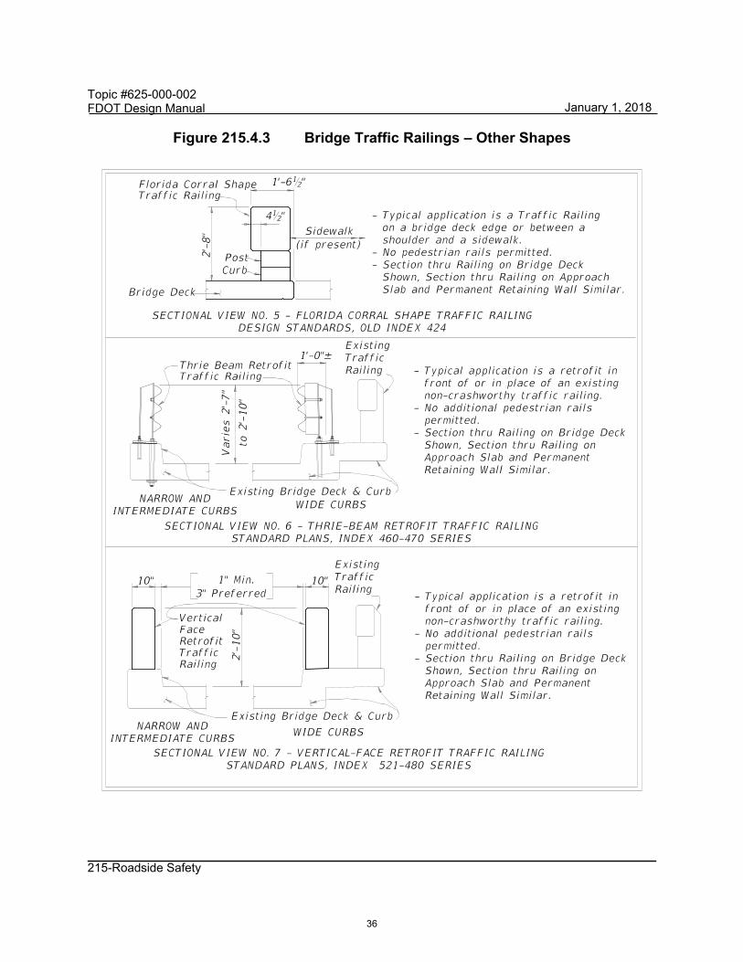
Details and typical applications of standard bridge railings are provided in Figures 215.4.1 – 215.4.10. Refer to FDM 222.4 for details of pedestrian/bicycle railings and fencing.
33
January 1, 2018

Topic #625-000-002 FDOT Design Manual
215-Roadside Safety
Figure 215.4.1 Bridge Traffic Railings – F-Shapes
34
January 1, 2018

Topic #625-000-002 FDOT Design Manual
215-Roadside Safety
Figure 215.4.2 Bridge Traffic Railings – Vertical Shapes
35
January 1, 2018
Topic #625-000-002 FDOT Design Manual
215-Roadside Safety
Figure 215.4.3 Bridge Traffic Railings – Other Shapes
36
January 1, 2018

Topic #625-000-002 FDOT Design Manual
215-Roadside Safety
Figure 215.4.4 Bridge Traffic Railings – Median Traffic Railing and Traffic Railing/Noise Wall Combination
37
January 1, 2018

Topic #625-000-002 FDOT Design Manual
215-Roadside Safety
215.4.1.4 Temporary Barriers
Temporary Barriers are used in work zones to protect motorists and as Positive Protection to safeguard construction workers while construction actives are taking place. General information about the application of Temporary Barriers can be found in Standard Plans, Index 102-100.
Temporary Barriers are installed in either ‘Anchored’ or ‘Free-standing’ conditions based on the barrier type and needed setback distance. See the Installation Data table provided in Standard Plans, Index 102-100 for the lateral offset and setback distance requirements.
Temporary Barriers include the following:
(1) Low Profile Barrier – Standard Plans, Index 102-120 (TL-2, NCHRP 350) (2) Type K Barrier – Standard Plans, Index 102-110 (TL-3, NCHRP 350) (3) Proprietary Temporary Barrier – See APL (TL-3, NCHRP 350 and MASH)
Low Profile Barriers are required for Work Zone Speeds of ≤ 45 mph where temporary barrier is needed within 100 feet of an intersection, residential driveway or business entrance. Use of other barriers is not permitted at these locations due to sight distance limitations. Low Profile Barrier can be used on bridges where no drop-off is present. Transitions from Low Profile Barrier to other temporary barriers within a run of barrier (i.e. from begin length of need to end length of need) is not permitted.
Type K Barrier is a portable concrete barrier which has the capability of being anchored (i.e. staked or bolted) to limit deflections or installed in a free-standing configuration. See Standard Plans, Index 102-110 for specific requirements for the use of Type K Temporary Concrete Barrier Refer to Standard Plans, Index 102-110 for details on transitioning between the Type K Temporary Concrete Barrier on bridges and other concrete barrier systems on the adjoining roadway.
Proprietary Steel Barriers (anchored only), Water Filled Barriers (free-standing only) and portable concrete barriers (free-standing or anchored) must be used in accordance with the Vendor drawings on the APL. To allow for the use of APL devices refer to temporary barrier the Plans as either ‘Anchored’ or ‘Free-standing’, unless specific limitations are required. Proprietary steel barriers listed on the APL are anchored to limit deflections; however, barrier heights and drainage performance may limit some systems.
Anchored (bolted) temporary barriers are not permitted on bridge superstructures that contain post-tensioned tendons within the concrete deck (top flange of concrete box
38
January 1, 2018

Topic #625-000-002 FDOT Design Manual
215-Roadside Safety
girders) or on bridge superstructures consisting of longitudinally prestressed, transversely post-tensioned, solid, or voided concrete slab units.
If Flexible (HTCB, Index D540-001) or Semi-Rigid (Guardrail, Index 536-001) barrier is used in a temporary configuration, or allowed to remain during a portion of the Temporary Traffic Control (TTC) Plan, requirements for the permanent application of barrier must be met; e.g., grading, deflection space, offset from Edge of Traveled Ways.
215.4.2 End Treatments
Non-crashworthy longitudinal barrier ends are hazards for approach direction when terminated within the clear zone. Crashworthy end treatments for each barrier type (flexible, semi-rigid, and rigid) are provided in the Standard Plans.
Flexible barrier end treatments are vendor-specific. For additional information regarding the end treatment of HTCB, refer to Developmental Standard Plans, Index D540-001, as referenced above.
215.4.2.1 Guardrail End Treatments
Guardrail end treatments are necessary to provide crashworthy ends for approaches and anchorage of the guardrail system. For the guardrail to provide adequate redirective capabilities during a vehicle impact, anchorage of the system is needed for tensile (ribbon) strength to develop in the guardrail panels. Approach terminals provide both anchorage of the guardrail system and a crashworthy approach. End treatments for guardrail are categorized as follows:
(1) Approach Terminals – required for guardrail ends within the clear zone of approaching traffic. Guardrail approach terminals must be a proprietary device listed on the APL. Approach terminals are classified by Test Level (TL-2 for Design Speeds ≤ 45 mph or TL-3, which is acceptable for all design speeds) and as follows:
(a) Flared – preferred terminal for locations where sufficient space is available to offset barrier end from approaching traffic.
(b) Parallel – use only when sufficient space is not available for a flared terminal.
(c) Double Face – preferred end treatment for double faced guardrail installations.
(2) Crash Cushion – See FDM 215.4.3.
39
January 1, 2018

Topic #625-000-002 FDOT Design Manual
215-Roadside Safety
(3) Trailing End Anchorages (Type II) – required for anchoring of the trailing ends of guardrail. Trailing end anchorages are non-crashworthy as an approach end treatment, and are not permitted as a guardrail end treatments on the approach end within the clear zone, unless shielded by another run of barrier. The Type II Trailing End Anchorage, is detailed in the Standard Plans, Index 536-001.
215.4.2.2 Rigid Barrier End Treatments
Terminate rigid barrier by either transitioning into another barrier system (e.g., guardrail), or by shielding with a crash cushion. Details and requirements are provided in the Standard Plans.
Sloped concrete end treatment using a vertical height transition, detailed in Standard Plans, Index 521-001, are not permitted within the clear zone of approaching traffic lanes. With sufficient justification the District Design Engineer may grant approval for use of this end treatment within clear zone for design speeds 35 mph and less, and only when no other more crashworthy solution is available.
Treatment of the trailing end of rigid barriers is not required unless additional hazards exist beyond the rigid barrier or the barrier is within the clear zone of opposing traffic.
215.4.2.3 Temporary Barrier End Treatments
The required treatments for exposed ends of temporary barriers are:
(1) Connecting to an existing barrier (smooth, structural connections are required - Refer to Standard Plans, Indexes 102-100 and 102-110, or the APL);
(2) Shield end with a crash cushion as detailed in the Standard Plans or APL for the specific type of temporary barrier (i.e. Temporary Concrete, Steel, or Water Filled); or,
(3) Flaring outside of the Work Zone clear zone (See Standard Plans, Index 102-600)
No modifications to the end treatments included in the Standard Plans or APL are permitted. Special conditions may require end treatments other than those included above. If this occurs, consult the State Roadway Design Office (RDO) and provide special details in the Plans.
40
January 1, 2018
Topic #625-000-002 FDOT Design Manual
215-Roadside Safety
215.4.3 Crash Cushions
Crash cushions (impact attenuators) are used to protect motorists from the exposed ends of barriers, fixed objects and other hazards within the clear zone. They are energy absorbing devices that may be redirective non-gating, or non-redirective gating. Crash cushions are classified based on Test Level and design speed, as shown for each system on their respective APL drawings.
The design of a crash cushion system must not create a hazard to opposing traffic. APL drawings provide details for transitions for optional barrier types with and without bi-directional traffic.
An impacting vehicle should strike the systems at normal height, with the vehicle's suspension system neither collapsed nor extended. Therefore, the terrain surrounding crash cushions must be flat (1:10 or flatter) in advance of and along the entire design length of the system. Do not locate curbs within the approach area of a crash cushion.
215.4.3.1 Permanent Crash Cushions
Permanent crash cushions must be redirective non-gating. Standard details of systems for typical installations shielding concrete barrier wall ends and guardrail ends can be found on the APL under Section 544. In addition, some of these systems have standard details for shielding wide hazards. For applications not covered in the APL drawings, crash cushion vendors normally provide design assistance for their systems. Special designs must be detailed in the Plans and based on meeting the performance criteria for the established design speed of the facility (i.e. barrier system Test Level).
215.4.3.2 Temporary Crash Cushions
Two types of temporary crash cushions are permitted;
Redirective non-gating crash cushions
Non-redirective gating crash cushions
Redirective crash cushions will shield hazards by redirecting errant vehicles impacting the side of the crash cushion and decelerate errant vehicles from a direct, in-line impact at the terminus of the crash cushion by absorbing the energy.
Gating crash cushions are designed to decelerate errant vehicles from a direct, in-line impact at the terminus of the crash cushion by absorbing the energy, but provide no redirective capabilities for side impacts. Use of gating crash cushions require approval
41
January 1, 2018

Topic #625-000-002 FDOT Design Manual
215-Roadside Safety
from the State Roadway Design Office (RDO). Gating cushions may be appropriate on low speed facilities and in work zones with higher speeds where only low impact angle hits are expected. An adequate clear runout area must be provided beyond a gating crash cushion (between the departure line and the clear zone). Plan details for site specific design are required.
Approved temporary crash cushions for use on Department contracts are listed on the APL under Section 102. Sand barrel gating systems are not permitted.
Anchored (bolted) temporary crash cushions are not permitted on bridge superstructures that contain post-tensioned tendons within the concrete deck (top flange of concrete box girders) or on bridge superstructures consisting of longitudinally prestressed, transversely post-tensioned, solid, or voided concrete slab units.
215.4.4 Barrier Transitions
Guardrail transitions are necessary, whenever standard W-Beam guardrail converges with rigid barriers. Guardrail transitions must include sound structural connections, nested panels and additional posts for increased stiffness. Use the guardrail transitions included in the Standard Plans as follows:
(1) General, Guardrail Approach Transition to Rigid Barrier – Index 536-001 (Single or Double Face Guardrail, TL-3, MASH), Approved for all Design Speeds.
(2) Low Speed, Guardrail Approach Transition to Rigid Barrier – Index 536-001 (Single Face Guardrail only, TL-2, MASH), Approved for Design Speeds ≤ 45 mph only with Flush Shoulder or Curb.
(3) Trailing End Transition Connection – Index 536-001 (Test Level N/A), Approved for all Design Speeds.
Various other barrier transitions are detailed throughout the Standard Plans and APL drawings for transitions from temporary barriers to permanent rigid barriers and transitions from variable height/shape rigid barriers.
215.4.5 Barrier Type Selection
Consider the following factors when determining the appropriate barrier type:
(1) Barrier Placement requirements (see FDM 215.4.6) (2) Traffic characteristics (e.g., volume, percent trucks)
42
January 1, 2018

Topic #625-000-002FDOT Design Manual
215-Roadside Safety
(3) Site characteristics (e.g., terrain, alignment, geometry, access facility type, accesslocations, design speed)
(4) Expected frequency of impacts(5) Initial and replacement/repair costs(6) Ease of maintenance(7) Exposure of workers when conducting repairs/maintenance(8) Aesthetics
For additional information about considerations for barrier selections refer to the AASHTO RDG. Document barrier type selection decisions and warrants.
215.4.5.1 Longitudinal Barrier Selection
There are four options for longitudinal barrier; HTCB, W-Beam Guardrail, Modified Thrie-Beam Guardrail, and Rigid Barriers. Table 215.4.1 provides guidance regarding roadway barrier type selection.
Specific requirements for the selection of HTCB are provided in the Standard Plans Instructions for Index D540-001.
Based on the limitations noted in FDM 215.4.1.2, the use of Modified Thrie-Beam Guardrail should be restricted to locations where site specific conditions warrant a more robust guardrail system but not the added cost of rigid barrier system.
Refer to the SDG for barrier type and test level selection of Traffic Railings.
43
January 1, 2018

Topic #625-000-002 FDOT Design Manual
215-Roadside Safety
Table 215.4.1 Roadway Barrier Type Selection
Barrier Type
Deflection Space
Requirement
Order of Bias
Test Level Design
Vehicles Initial Cost
Vehicle Impact
Severity
MaintenanceCost
(feet)
HTCB 12 LOW LOW HIGH TL-4
(NCHRP 350)
Passenger Car, Pickup
Truck, & Single-Unit
Truck
W-Beam Guardrail
5 TL-2 & TL-3 (MASH)
Passenger Car & Pickup Truck
Modified Thrie-Beam Guardrail
3 TL-4 (NCHRP 350)
Passenger Car, Pickup
Truck, & Single-Unit
Truck
Rigid Barrier
0 HIGH HIGH LOW TL-3, TL-4 &
TL-5 (MASH)
Passenger Car, Pickup
Truck, Single-Unit
Truck & Tractor-Van
Trailer
215.4.5.2 End Treatment Selection
Select end treatments in accordance with FDM 215.4.2, the Standard Plans and the Standard Plans Instructions for each applicable barrier type.
44
January 1, 2018

Topic #625-000-002FDOT Design Manual
215-Roadside Safety
215.4.5.3 Crash Cushion Selection
Various types of energy absorbing devices eligible for use on Department projects ascrash cushions can be found on the APL. Detailed information about these systems isprovided in the Standard Plans, APL, and in each manufacturer’s publications. Each system has unique physical and functional characteristics.
For permanent crash cushion applications, indicate in the Plans the requirements for eachgiven location in accordance with Standard Plans, Index 544-001, and FDM 307,including the:
(1) Location (station and side),(2) Barrier system (concrete barrier wall or guardrail),(3) Design length,(4) Design speed,(5) Crash test level, and(6) Hazard width and length restriction.
Site characteristics and economics dominate crash cushion selection considerations.Some crash cushion systems are relatively low in initial cost, but usually must becompletely replaced when struck, so are more appropriate in locations with a lowlikelihood of collision. There are a number of other systems that have higher initial costsbut can be repaired after collisions relatively quickly and inexpensively, so are moreappropriate where frequent collisions are anticipated. The ability of maintenance forcesto perform routine maintenance and to place a crashed system back into service quicklyshould be a major consideration. Do not use crash cushions that require stocking unusualand expensive parts or those that are complex to replace.
215.4.5.4 Pier Protection
In addition to shielding bridge piers to protect motorists from a hazard within the clearzone, bridge piers may need shielding for protection from damage due to designlimitations (i.e. piers not designed for vehicular collision forces). Coordination with theStructural Engineer of Record is required to determine if pier protection is warranted.
The requirements for Pier Protection are outlined in the SDG, Section 2.6. The processfor determining the appropriate level of Pier Protection for New Construction projects ispresented in Figure 215.4.5 (Pier Protection Selection Flowchart). For RRR and railroadrequirements, refer to the SDG. Detail Pier Protection barrier in accordance withStandard Plans, Index 521-002.
45
January 1, 2018

Topic #625-000-002 FDOT Design Manual
215-Roadside Safety
Figure 215.4.5 Pier Protection Selection Flowchart (New Construction)
Start
Is offset from column to edge of traveled
way < 30' ?(1)
Is AFHPB:< 0.0001 Critical Bridge?< 0.001 Typical Bridge?
(1), (2)
Is columnwithin clear zone or
lateral offset?(3)
Design for600 kip load?
(1)
No barrier or guardrail required
Use 44" barrier per (5)
Use 56" barrierper (5)
Provide barrier per (4)
Is offset from barrier to column
< 10'-9" ?(5)
LEGEND
(1) – LRFD 3.6.5.1
(2) – SDG 2.6.1.A
(3) – FDM 215.2
(4) – Index 536-001 or521-001, and FDM Table 215.4.2
(5) – Index 521-002
Yes
No
Yes
No
No Yes
YesNo
No
Yes
January 1, 2018
46

Topic #625-000-002 FDOT Design Manual
215-Roadside Safety
215.4.6 Barrier Placement
The primary design factors associated with barrier placement are:
(1) Lateral Offset from the Edge of Traveled Way, (2) Deflection Space Tolerance, (3) Terrain Effects, (4) Length of Need, (5) Space for End Treatments, and (6) Outside Shoulder or Median Application
215.4.6.1 Barrier Offset
Offset roadside barriers as far from the travel lanes as practical with consideration for maintaining the proper performance of the barrier. See Developmental Standard Plans Instructions for Index D540-001 for the barrier placement requirements for HTCB.
Requirements for guardrail offsets are illustrated in Figure 215.4.6.
For flush shoulder roadways the standard offset for W-Beam Guardrail from the Edge of Traveled Way is the shoulder width plus 2 feet, not to exceed 12 feet. The 12 feet maximum offset for guardrail is established to reduce the potential for impacts where the vehicle is behaving significantly different than the crash tested conditions (i.e. non-tracking, fish-tailing, excessive approach angle, etc.). Guardrail offsets greater than 12 feet require site-specific justification in accordance with FDM 215.4.7, unless location is based on the requirements of FDM 215.4.6.4, Median Barrier or FDM 215.3.2, Canal Hazards.
When curb is present, the preferred configuration is to place the face of the guardrail panel 5 inches from the face of curb. For design speeds ≤ 45 mph, the face of the guardrail panel may also be placed between 4 feet and 12 feet from the face of curb.
Rigid Barrier is typically used when there are barrier deflection or right-of-way limitations. Rigid Barrier offsets should be based on site-specific conditions, but as far from the traveled way as possible.
Rigid Barrier, with the exception of F-Shape or Single-Slope barriers with a height less than 42”, may be used in combination with curbs, and provide an acceptable alternative to the areas excluded for guardrail use in Figure 215.4.6.
47
January 1, 2018

Topic #625-000-002 FDOT Design Manual
215-Roadside Safety
Figure 215.4.6 Lateral Offset to Guardrail
48
January 1, 2018

Topic #625-000-002 FDOT Design Manual
215-Roadside Safety
In addition to travel lane lateral offset considerations, an adequate setback must be provided behind the barrier to ensure proper function. For flexible and semi-rigid barriers the setback is based on deflection tolerances and is required to prevent the barrier from contacting aboveground hazards.
For rigid barriers the setback is required to keep the area above and behind the barrier face free of obstructions that could penetrate or damage the vehicle compartment. This requirement is based on the “Zone of Intrusion” concept as described in the AASHTO RDG. Table 215.4.2 provides the Setback requirements for FDOT standard barriers. Additionally, Figure 215.4.7 includes setback distances to rigid barriers for discontinuous elements. These requirements do not apply to devices detailed in the Standard Plans as attachments to rigid barriers (e.g., pedestrian/bicycle bullet railing, bridge fencing, traffic railing/noise wall combinations).
49
January 1, 2018

Topic #625-000-002 FDOT Design Manual
215-Roadside Safety
Table 215.4.2 Minimum Barrier Setback (Measured from the face of the barrier)
Barrier Type Setback Distance
Flexible Barrier
High Tension Cable Barrier (HTCB) 12 feet, 0 inches
Semi-Rigid Barrier
W-Beam with Post Spacing @ 6 feet, 3 inches (TL-3) 5 feet, 0 inches W-Beam with Post Spacing @ 12 feet, 6 inches (TL-2) 5 feet, 0 inches W-Beam with Post Spacing @ 3 feet, 1.5 inches (½ Spacing) 3 feet, 10 inches W-Beam with Post Spacing @ 1 foot, 6.75 inches (¼ Spacing) 3 feet, 2 inches Nested W-Beams with Post Spacing @ 3 feet, 1.5 inches (½ Spacing) 3 feet, 0 inches Nested W-Beams with Post Spacing @ 1 foot, 6.75 inches (¼ Spacing) 2 feet, 8 inches Deep Post W-Beam installed on 1:2 Slope Break with Post Spacing @ 6 feet, 3 inches (TL-3) 5 feet, 6 inches
Modified Thrie-Beam with Post Spacing @ 6’-3” 3 feet, 0 inches
Rigid-Barrier
Concrete Barrier < 40” Height (Design Speeds ≤ 45 MPH) 0 feet, 0 inches Concrete Barrier < 40” Height (Design Speeds > 45 MPH) Non-crash Tested Continuous or Discontinuous Items 1 foot, 6 inches
Concrete Barrier ≥ 40” Height 0 feet, 0 inches Bridge Traffic Railing < 40” Height
Non-crash Tested Continuous Items Non-crash Tested Discontinuous Items
5 feet, 0 inches See Figure 215.4.7
Temporary Barriers
See “Setback Distance” of applicable Standard Plans, Index or APL drawing.
50
January 1, 2018

Topic #625-000-002 FDOT Design Manual
215-Roadside Safety
Figure 215.4.7 Setback Distances for Discontinuous Elements
Noise Wall/Traffic Railing combinations located within the setback distance must be crash tested to or accepted as TL-4 under MASH. Other continuous items (e.g., glare screens and fences) located within this setback distance must be crash tested to or accepted as TL-3 under NCHRP 350 or MASH.
See FDM 215.5 for additional information regarding discontinuous attachments to rigid barriers.
215.4.6.2 Grading Requirement
The terrain effects between the traveled way and a barrier can have a significant impact on whether or not a barrier will perform as intended. Proper grading around a barrier will ensure that as a vehicle approaches a barrier its suspension is not dramatically affected, causing the vehicle to underride or override a barrier.
51
January 1, 2018

Topic #625-000-002FDOT Design Manual
215-Roadside Safety
Install barriers on slopes 1:10 or flatter. Continue the 1:10 slope a minimum 2 feet beyondthe barrier (i.e. from either the guardrail post or rigid barrier) before providing a slopebreak.
With approval of the District Design Engineer and where conditions are constrained, theDeep Post guardrail option may be used in lieu of providing a 2-feet setback to the slopebreak point. Coordinate the use of the Deep Post guardrail option with the DistrictDrainage Engineer and District Maintenance Engineer. See Deep Post details inStandard Plans, Index 536-001 “Slope Break Condition”.
Modification for Non-Conventional Projects:
Delete the last paragraph and see RFP for requirements.
Proper grading around crashworthy end treatments is essential to assure the deviceperforms as intended. Grading requirements are shown in the Standard Plans.
For superelevated roadway sections, a maximum 7% algebraic difference is permittedbetween the travel lanes and shoulder in advance of barriers. See FDM 215.4.6.5 fortemporary barrier requirements in superelevated roadway sections.
215.4.6.3 Length of Need
Length of need is dependent on:
(1)(2)(3)(4)
Barrier typeDesign speedOffset distance to the face of the barrierThe lesser distance to either the back of the hazard or to the clear zone
Use the requirements provided in the Standard Plans Instructions or the Standard Plans to establish length of need for each barrier type.
52
January 1, 2018

Topic #625-000-002 FDOT Design Manual
215-Roadside Safety
215.4.6.4 Continuous Median Barriers
Continuous median barriers are used to mitigate median crossover crashes (i.e., reduce the number of vehicles that might enter opposing lanes of traffic after traversing a median).
Locate continuous median barrier in accordance with guidelines included in the AASHTO RDG, Section 6.6 and in accordance the Standard Plans.
In locations where a continuous median barrier is present, the length of a barrier opening should be minimized to the extent practical. As shown in FDM Exhibit 211-3, the barrier ends on each side of the opening should be offset. Provide crashworthy end treatments or crash cushions to shield the barrier ends when the ends are within the clear zone and fall within the departure angle used to set length of need. Provide crashworthy end treatments or crash cushions when the angle between barrier ends is less than 30 degrees measured from the direction of mainline travel.
The preferred barrier option for continuous median barrier is High Tension Cable Barrier (HTCB), provided the requirements of the Developmental Standard Plans Instructions for Index D540-001 can be met. Evaluate other barrier options when the deflection and placement requirements for HTCB cannot be met.
Include Rub Rail on double faced w-beam guardrail installations as shown in Standard Plans, Index 536-001. Based on the shoulder width and as shown in Figure 215.4.6, locate double faced w-beam guardrail at a lateral offset of between 8 feet and 12 feet from the edge of traveled way. For medians with cross slopes of 1:6 of flatter, locate the barrier closest to the traveled way with the most likelihood or history of lane departure (e.g., outside of horizontal curves and sections with outside merge lanes). If median cross slopes greater than 1:6 exist, and HTCB is not feasible, install w-beam guardrail along both sides of the median or consider a grade separated (bifurcated) median with a concrete barrier.
Use concrete median barrier when the barrier offset requirements for flexible or semi-rigid barrier cannot be met or a higher test level barrier is justified. Implement concrete median barrier in accordance with Standard Plans, Index 521-001.
215.4.6.5 Requirements for Culverts
Roadside barriers placed at a culvert (i.e., box culvert, bridge culvert, or three-sided culvert) should be either W-Beam Guardrail or Bridge Traffic Railing. See Chapter 6 of the Structures Design Guidelines for more information regarding bridge traffic railings.
53
January 1, 2018

Topic #625-000-002 FDOT Design Manual
215-Roadside Safety
W-Beam Guardrail is the preferred barrier option, provided the grading, post embedment and length of need requirements can be met. A minimum of 4 feet of fill must be provided over the culvert for adequate post embedment and performance. If there is less than 4 feet of fill over the culvert, utilize one of the following options:
(1) Culverts with total overall widths ≤ 5 feet: use W-Beam Guardrail with a post layout that straddles the outside of the culvert using standard post spacing of 6’-3”.
(2) Culverts with total overall width between 5 feet and 20 feet: use shortened W-Beam guardrail posts (e.g., Encased Post for Shallow Mount). See Design Standards, Index 400.
(3) Culverts with total overall width > 20 feet: use a project specific designed metal traffic railing similar to the Thrie-Beam Retrofit barriers (i.e. thrie-beam railing attached directly to the culvert headwall), see the Standard Plans, Index 460 Series. Designers should note that the locations of the first and last posts are critical. Headwalls must be a minimum of 18 inches wide and the base plate must be located so that it is located at least 12 inches away from any construction joint or free end of the concrete headwall.
Placement of base plates and bolts in the top slab of the culvert barrel should be avoided because they are difficult to repair and maintain, the necessary anchor embedment lengths are problematic to obtain, and they are potentially damaging to the top of the culvert barrel.
Concrete rigid barrier or bridge traffic railing is typically not used due to the short length of culverts, unless continued along the roadway for other reasons.
215.4.6.6 Temporary Barriers
Installation instructions and flare rates are given in Standard Plans, Indexes 102-100, 102-110, 102-120 and 102-600.
A temporary or permanent pavement surface with a maximum cross slope of 1:10 is required when a temporary barrier is used. Refer to Standard Plans, Index 102-100 for setback distance and asphalt pad requirements.
Show or note the location of temporary barriers in the Temporary Traffic Control (TTC) Plans. Also provide a Work Area Access Plan for projects with work zones shielded with a barrier. For additional information regarding TTC Plans, refer to FDM 240.
The presence of barriers on both shoulders may eliminate any effective shoulder width or refuge area. The effective shoulder width is required to ensure an area is available for
54
January 1, 2018

Topic #625-000-002 FDOT Design Manual
215-Roadside Safety
both disabled vehicles during normal traffic conditions and access for emergency responders during stopped conditions. Therefore, on interstate, freeway, and expressway projects requiring barriers on both sides of the work zone traveled way, a minimum 10-foot lateral offset from the edge of the traveled way to the barrier is required on at least one side of the roadway. Bridge construction and associated roadway approaches are exempt from this requirement. Providing this 10-foot lateral offset on arterials and collectors should be considered. For all other applications, provide the minimum lateral offset required per Standard Plans, Index 102-100.
When using existing barrier during a temporary traffic control operation or when 2-way traffic is placed on a facility that is normally one-way, the existing permanent or temporary barriers must be modified as necessary to ensure their proper crashworthiness during the temporary situation. This will include eliminating non-crashworthy end treatments, snag points or other protrusions normally angled away or hidden from approaching vehicles.
Existing permanent barriers used during temporary traffic control operations must meet grading, offset, and setback (i.e. deflection space) requirements for the permanent installation.
Temporary barriers, as defined in FDM 215.4.1.4, located in superelevated roadway sections must be installed on the same roadway cross slope as the travel lanes (i.e. no slope break in advance of the barrier).
215.4.7 Warrants for Roadside Barriers
The installation of roadside barriers presents a hazard in and of itself, and as such, requires an analysis for whether or not the installation of a barrier presents a greater risk than the feature it is intended to shield. The analysis should be completed using the Roadside Safety Analysis Program (RSAP) or in accordance with the AASHTO Highway Safety Manual (HSM). Refer to FDM 122.6 for guidance on evaluating the benefits of shielding using RSAP or the HSM.
Roadside barriers are recommended when hazards exist within the clear zone, hazards cannot be cost effectively eliminated or corrected, and collisions with the hazards are more serious than collisions with the barriers.
The following conditions within the clear zone are considered more hazardous than a roadside barrier:
(1) Drop-off Hazards, as defined in FDM 215.3.3. (2) Bridge piers, abutments and railing ends.
55
January 1, 2018

Topic #625-000-002 FDOT Design Manual
215-Roadside Safety
(3) Non-traversable culverts, pipes and headwalls. (4) Non-traversable parallel or perpendicular ditches and canals. (5) Canals, ponds and other bodies of water. (6) Parallel retaining walls with protrusions or other potential snagging features. (7) Retaining walls at an approach angle with the edge of pavement larger than 7
degrees (1:8). (8) Non-breakaway sign or luminaire supports. (9) Trees greater than 4 inches in diameter measured 6 inches above the ground. (10) Utility poles. (11) Weaving Sections, as defined in FDM 211.12.1.
215.4.7.1 Treatment of Roadside Hazards
If a hazard, including slopes steeper than 1:3, is present within the clear zone, eliminate or shield the hazard, except when any of the following apply:
Longitudinal barrier or crash cushion would be a greater hazard than the hazard to be shielded
The likelihood of striking the hazard is negligible
The expense of shielding the hazard outweighs the benefits in terms of crash reduction as determined through the use of RSAP or HSM analyses.
If crash data or safety reports indicate that treatment of the hazard will result in fewer or less severe crashes, implement one of the following treatments, in order of priority:
(1) Eliminate the hazard. (a) Remove the hazard. (b) Relocate the hazard outside the clear zone. (c) Make the hazard traversable or crashworthy.
(2) Shield the hazard with a longitudinal barrier or crash cushion.
56
January 1, 2018

Topic #625-000-002FDOT Design Manual
215-Roadside Safety
215.4.8 Warrants for Median Barrier
Provide a median barrier on LA Facilities when:
(1) Reconstruction reduces the median width to less than what is required for thefacility. Deviation from this criteria is not permitted. An RSAP or HSM analysismay be used to evaluate barrier alternatives and supplement the followingrequirements.
(2) One or more crossover crashes have occurred in the most recent 5-year periodwithin the limits of 1 mile in advance of the exit ramp gore to 1 mile beyond theentrance ramp gore. The District may require shielding outside these areas afterreviewing the most recent 5-year crash history.
On divided arterial and collector projects with design speed greater than 45 mph, reviewthe most recent 5-year crash history for crossover crashes to determine if shielding witha median barrier is warranted. Consider alignment, sight distance, median width andfrequency of median openings when evaluating the facility.
215.4.9 Positive Protection in Work Zones
For locations where work zone traffic barriers are required, refer to Standard Plans, Index 102-600. Work zone traffic barriers are positive protection devices and temporarybarriers that can be easily relocated. They have four specific functions:
(1) Protect traffic from entering work areas (e.g., excavations or material storagesites).
(2) Provide positive protection for workers.(3) Separate two-way traffic.(4) Protect construction such as false work for bridges and other exposed objects.
Anticipate when and where barriers will be needed and include this information and thequantities on the Plans. Consider positive protection devices in work zone situations thatplace workers at increased risk from vehicular traffic, and where positive protectiondevices offer the highest potential for increased safety for workers and road users, suchas:
(1) Work zones that provide workers no means of escape from vehicular traffic (e.g.,tunnels, bridges).
(2) Long duration work zones (two weeks or more at the same location) resulting insubstantial worker exposure to vehicular traffic.
57
January 1, 2018

Topic #625-000-002 FDOT Design Manual
215-Roadside Safety
(3) Projects with anticipated Work Zone speeds greater than 45 mph, especially when combined with high traffic volumes.
(4) Work operations that place workers close to travel lanes open to traffic. (5) Roadside hazards (e.g., drop-offs, unfinished bridge decks) that will remain in
place overnight or longer.
Modification for Non-Conventional Projects:
Delete the first sentence of the above paragraph and see RFP for requirements.
215.5 Attachments to Barriers
Allowable attachments to flexible or semi-rigid barriers (discontinuous or continuous) are detailed in the Standard Plans.
Use Standard Plans, Index 700-012 for signs attached to rigid barrier. Standard Plans, Index 700-013 can only be used to mount permanent signs to non-median rigid barriers when there is insufficient space for Standard Plans, Index 700-012 and the sign is critical to safety.
Design and detail attachments to rigid barriers in accordance with SDG 1.9. Provide setback distances as shown in Table 215.4.2 and Figure 215.4.13 to non-crash tested discontinuous items (e.g., light poles, sign supports, traffic signal controller boxes, flood gauges) that are attached to or behind rigid barriers located along the outside shoulder. Discontinuous items located within these setback distances must be crash tested to or accepted as TL-3, at a minimum, under NCHRP 350 or MASH as attachments to traffic railings.
For continuous items attached to rigid barriers, refer to the requirements of FDM 215.4.6.1.
Fender access ladders are exempt from these requirements. Sign panels may be placed within the given setback distances, however the setback to the sign support must be increased to assure sign panels do not extend past the top inside face of the traffic railing.
215.5.1 Median Barrier Attachments
Use Standard Plans, Index 715-002 for light poles installed in conjunction with concrete median barriers or traffic railings. Overhead sign supports may be located on rigid barriers within the median to reduce span or cantilever lengths and provide more cost
58
January 1, 2018

Topic #625-000-002 FDOT Design Manual
215-Roadside Safety
effective designs. When placing overhead sign supports on rigid barriers within the median, project specific details that supplement Standard Plans, Index 521-001 (e.g., foundation and reinforcement details) are required to be shown in the Plans.
Single column sign supports mounted on rigid barriers within the median are permitted only when requirements for sign visibility cannot be met by placing the sign supports on the outside of the shoulder barrier or beyond the shoulder. If single column sign supports must be mounted on a median traffic railing, utilize Standard Plans, Index 700-013. The signs listed in FDM 230.2.5 are the only permanent signs that may be used with Standard Plans, Index 700-013.
These requirements also apply to attachments made to back-to-back outside shoulder rigid barriers that are located so close together that the required setback distances cannot be provided for both barriers. The bridge traffic railings and supporting decks shown in Figure 215.4.13 that are located back-to-back are exempt from these requirements.
215.5.2 Existing Attachments to Barriers and Traffic Railings
Evaluate existing rigid barrier attachments on a case-by-case basis to ensure they are installed in accordance with the FDM and Standard Plans, Indexes 700-012, 700-013, or 715-002. Remove existing attachments not meeting these requirements.
215.5.3 Temporary Attachments to Barriers
Standard Plans, Index 700-013 may be used for temporary work zone signs when the application of Standard Plans, Index 102-600 cannot be achieved.
For additional information on the design of temporary lighting in combination with temporary barrier, refer to FDM 240.4.2.13.
59
January 1, 2018

Topic #625-000-002FDOT Design Manual
215-Roadside Safety
215.6 Surface Finishes
Class 5 coatings, tints or stains may be applied to roadway concrete barriers in order tobe compatible with the treatment of bridge or retaining wall mounted traffic railings or forcorridor uniformity. The follow approvals are required for use of Class 5 coatings:
(1) District Design Engineer approval when applied on the outside of concrete barriers.(2) Chief Engineer approval when applied to median barriers and the inside and top
surfaces of concrete barriers.
Abrupt changes of aesthetic treatment of barriers, railings or parapets from a bridge to aroadway should be avoided. See SDG, Section 1.4.5 for the policy on bridge, noise walland retaining wall surface finishes.
The Department will cover the cost for coating, tints or stains on roadway concretebarriers only as described above. If a Local Maintaining Agency desires a roadwayconcrete barrier with coatings, tints or stains and the concrete barrier does not qualify forsuch treatment as determined by the Department, the barrier may be treated withapproval by the District Secretary. The Local Maintaining Agency must provide theadditional construction funding for the coatings, tints, or stains and must commit to coverthe associated maintenance costs for the service life of the barrier.
Modification for Non-Conventional Projects:
Delete FDM 215.6 and see RFP for requirements.
215.7 Existing Barrier Systems
When barrier systems are present on a project for which reconstruction of the roadside isnot required, the existing barrier should be evaluated to determine if the barrier meetscurrent structural, functional and crashworthy requirements. Remove or replace anybarrier installation which is found to be non-crashworthy or crash tested prior to NCHRP 350 test criteria. The evaluation should consider the following:
(1) Warrants for the barrier. See FDM 215.4.4.(2) Length of need.(3) Guardrail panel height.(4) Offset at terminal end.
60
January 1, 2018

Topic #625-000-002 FDOT Design Manual
215-Roadside Safety
(5) Clear deflection distance between the barrier and the shielded object. (6) Placement with respect to the traveled way, or face of curb. (7) Placement on the proper slope. (8) Clear recovery area behind gating end terminals. (9) Overall condition of the barrier system. (10) Post type and spacing.
In addition to the above evaluation requirements, existing roadside safety hardware must comply with the requirements of the following Sections.
215.7.1 Resetting Guardrail
For installations of guardrail where the barrier is determined to be deficient or requires relocating due to other work, but otherwise determined to consist of panels in good condition, the guardrail may be reset. If the guardrail system is determined to be non-reusable, remove and replace with new guardrail. Refer to Standard Specification 538 for additional information on reusable and non-reusable guardrail components.
When resetting existing guardrail, the guardrail will be reinstalled as 31” Guardrail reusing existing guardrail panels and posts (steel only) as shown in the current Standard Plans, Index 536-001. This resetting requires panels be reinstalled with the panel splices located at the midspan; therefore, consideration must be given to the effect this will have on the overall system length and if adjustments to the Begin/End Guardrail Station are needed.
Rigid-barrier approach transitions, approach end terminals and trailing anchorages must be replaced with new hardware, panels, and posts when resetting guardrail.
215.7.2 Existing Longitudinal Roadway Barriers
Existing longitudinal guardrail sections that do not conform to 31” Guardrail must be upgraded or replaced, with the following exceptions:
(1) 27” Guardrail – Existing W-Beam guardrail installations installed to a 1’-9” mounting height (27” top height), meeting the requirements of the 2013 Design Standards with regards to delineation, height, deflection distance, grading, mounting hardware, and consisting of crashworthy end treatments tested to at least NCHRP 350, is acceptable and allowed to remain in place.
61
January 1, 2018

Topic #625-000-002 FDOT Design Manual
215-Roadside Safety
(2) Thrie-Beam Guardrail – Existing Thrie-Beam guardrail meeting the installation requirements of 2013 Design Standards, and consisting of crashworthy end treatments tested to at least NCHRP 350, is acceptable and allowed to remain in place.
(3) Steel Blocks – Existing 27” Guardrail constructed with steel blocks, which is not being evaluated for upgrading according to the criteria above, may remain in place for projects with Design Speeds ≤ 45 mph.
Replacing or resetting existing 27” Guardrail to meet the 31” Guardrail mounting height requirement is at the discretion of the District. Typically, if 50% or more of an existing run of 27” Guardrail is affected or if the existing installation is extended by 50% or more, the entire run should be replaced or reset with 31” Guardrail. The required clear deflection distances for 31” Guardrail are greater than the requirements for 27” Guardrail and should be considered when resetting guardrail to the new height.
Modification for Non-Conventional Projects:
Delete the last paragraph and see RFP for requirements.
Existing concrete barriers conforming to the current Standard Plans, Index 521-001, F-Shape, New Jersey shape barriers, and approved vertical faced concrete barriers may remain in place. Other concrete barrier shapes must be replaced.
Replacements and new installations must conform to the current Standard Plans.
See FDM 215.4.5.4 and SDG, Section 2.6, for barrier requirements for Pier Protection.
215.7.3 Existing End Treatments & Crash Cushions
Evaluate concrete barrier end treatments to ensure adequate length of need is provided and meet crashworthiness requirements. Remove or replace end treatments and crash cushions which are found to be non-crashworthy or crash tested prior to NCHRP 350 test criteria . Existing guardrail end treatments must be upgraded or replaced unless they conform to one of the systems identified on the APL, the current Standard Plans, or the 2013 Design Standards.
Replacements and new installations must conform to the current Standard Plans.
62
January 1, 2018

Topic #625-000-002 FDOT Design Manual
215-Roadside Safety
215.7.4 Existing Bridge Traffic Railing
Evaluate bridge traffic and pedestrian railings for conformance to current FDM criteria and Standard Plans whenever improvements are made to a bridge or its approach roadway. For non-compliant bridge railings:
(1) Retrofit bridge railing to bring them up to current standards, or (2) Replace bridge railing, or (3) Process a Design Variation, provided that a subsequent project that will remedy
this condition is scheduled within a reasonable time.
See SDG 6.7 for traffic railing requirements, and SDG 6.8 and the following for pedestrian railing requirements.
Remove existing fences that are not in compliance with Standard Plans, Indexes 515-010 or 515-012, and existing pedestrian railings that are mounted on existing traffic railings located between the shoulder and the sidewalk (a.k.a. "inboard" traffic railings). Replace or retrofit the existing pedestrian railing or fence rather than completely removing it if there is a documented issue of traffic incidents involving pedestrians (at the site before installation of the existing pedestrian railing or fence on the inboard traffic railing) that would likely reoccur if the existing installation were to be removed. Use Standard Plans, Indexes 515-010 or 515-012, or another crashworthy pedestrian railing or fence that is compatible with the traffic railing, as appropriate. Retrofit existing bullet-type railings that are to remain on inboard traffic railings and that do not have the bullet railing member(s) oriented towards the traffic side of the railing to match Standard Plans, Index 515-021.
Retrofit existing installations of Standard Plans, Index 515-021, and other similar bullet-type railings, to include rail splice assemblies and tapered end transitions as shown on Standard Plans, Index 515-022 if they are not present. Retrofit the ends of other existing crashworthy traffic railing mounted pedestrian railings to include a similar tapered end transition, or other appropriate approach end transition, if one is not present.
215.7.5 Existing Guardrail to Bridge Railing Transitions
Existing guardrail to bridge traffic railing approach and trailing end transitions must be upgraded or replaced unless they conform to one of the following systems:
(1) For approach ends of existing standard New Jersey Shape, F-Shape, and Single-Slope bridge traffic railings:
63
January 1, 2018

Topic #625-000-002 FDOT Design Manual
215-Roadside Safety
(a) The nested Thrie-Beam approach transition shown as in the current Standard Plans or the 2013 Design Standards, Index 400.
(b) For retrofitted installations, the appropriate nested Thrie-Beam transition shown in the current Standard Plans or the 2013 Design Standards, Index 402.
(c) For a design speed ≤ 45 mph the nested w-beam approach transition shown as Detail J in the 1998 Roadway and Traffic Design Standards, Index 400, Sheet 7 of 21. This detail is also shown in the 2000 Roadway and Traffic Design Standards, Index 401, Sheet 1 of 9.
(2) For approach ends of existing bridge traffic railing retrofits constructed in accordance with the 1987 through 2000 Roadway and Traffic Design Standards, Index 401, Schemes 1 and 19, “Concrete Safety Barrier”:
(a) The appropriate nested Thrie-Beam transition shown in Standard Plans, Index 536-002.
(b) For design speeds ≤ 45 mph the w-beam approach transition shown as Detail J in the 1987 Roadway and Traffic Design Standards, Index 400, Sheet 9 of 13, upgraded as shown in the 2013 Design Standards, Index 403 by the installation of a nested section of W-beam guardrail, additional guardrail posts and offset blocks and a transition block if a curb is not present beyond the bridge end.
(c) For design speeds ≤ 45 mph the nested W-beam approach transition shown as Detail J in the 1998 Roadway and Traffic Design Standards Sheet 7 of 21, upgraded as shown in the 2013 Design Standards, Index 403 by the installation of a transition block if a curb is not present beyond the bridge end.
(3) For trailing ends of existing bridge traffic railing retrofits constructed in accordance with the 1987 through 2000 Roadway and Traffic Design Standards, Index 401, Schemes 1 and 19, “Concrete Safety Barrier”:
(a) In the absence of additional hazards on the trailing end, no end treatment is required.
(b) When additional hazards are present on the trailing end, a w-beam trailing end treatment as shown in Standard Plans, Index 536-001.
(4) For approach ends of existing structurally continuous Post and Beam bridge traffic railings that are not being retrofitted per FDM 215.7.4:
(a) A custom designed nested Thrie-Beam approach transition based on the current Standard Plans, Index 536-001.
(b) A nested Thrie-Beam approach transition based on the current Standard Plans, Indexes 536-002, 521-404 or 521-405.
64
January 1, 2018

Topic #625-000-002 FDOT Design Manual
215-Roadside Safety
(c) A custom designed nested Thrie-Beam approach transition based on the 1987 through 2000 Roadway and Traffic Design Standards, Index 401, Scheme 29.
(5) For trailing ends of existing structurally continuous Post and Beam bridge traffic railings that are not being retrofitted, per FDM 215.7.4:
(a) In the absence of additional hazards on the trailing end, no end treatment is required.
(b) When additional hazards are present on the trailing end, a w-beam trailing end treatment as shown in the current Standard Plans, Index 536-001 or the 1987 through 2000 Roadway and Traffic Design Standards, Index 401.
(c) When additional hazards are present on the trailing end, a custom designed nested Thrie-Beam approach transition based on any design listed in No. 4 above.
Guardrail replacements and new installations connecting to standard New Jersey Shape F-Shape, and Single-Slope bridge traffic railings must conform to the current Standard Plans, Index 536-001. For guardrail retrofits connecting to existing bridge traffic railings, see the current Standard Plans, Indexes 536-002 or 460-477 and their associated Standard Plans Instructions.
Guardrail replacements, retrofits and new installations connecting to structurally continuous post and beam bridge traffic railings must conform to Design Standards, Indexes 404 or 405 and their IDS. See the IDS for details of structurally continuous post and beam traffic railings.
65
January 1, 2018

Topic #625-000-002 FDOT Design Manual
215-Roadside Safety
215.8 Non-Standard Roadside Safety Hardware
The APL includes proprietary devices and products that have been evaluated for compliance with FDOT Standard Specifications and the Standard Plans. The majority of proprietary roadside safety hardware eligible for use on the State Highway System are identified on the APL. However, the devices included on the APL may not cover every roadside safety application. Unique situations will sometimes require unique devices. Examples of available devices that are not covered by the APL include but are not limited to barrier wall gates, aesthetic guardrail, temporary steel barriers, and crashworthy stop gates. When the need arises for a unique crashworthy device not included on the APL, carefully investigate the applicability of the device for the situation, as well as the crash performance characteristics of the device. For some of these devices, the State Roadway Design Office (RDO) may have information and be of assistance in establishing the appropriateness of the device for a given situation.
Provide the following documentation when requesting the approval of a device not included on the APL:
(1) FHWA, Federal-Aid Reimbursement Eligibility Letter (2) Crash Test Reports, including review of test results. Performance characteristics
must be reviewed, including post impact vehicle behavior and post impact test article deflection, and debris scatter.
(3) Compatibility with adjacent and/or connecting standard roadside safety devices. (4) Maintenance requirements and characteristics, including coordination with the
District Maintenance Office. (5) For devices such as barrier gates, operational plans and training as appropriate.
The use of Non-Standard Roadside Safety Hardware must be approved by the State Roadway Design Office (RDO).
Project specific plan details, technical special provisions (TSP), and method of payment will be required and must be coordinated with the appropriate Department Offices.
Other barrier designs may be required by specific site conditions. Site specific conditions are identified and detailed in the plans.
66
January 1, 2018