2118150 200 lbs tow spreader - tractor supply … f o r t h loosen bolts to adjust wing knob...
TRANSCRIPT

1
MODEL # BS0303-200
200 LB. COMMERCIAL TOW SPREADER
SKU # 2118150
USER MANUAL
READ USER MANUAL CAREFULLY BEFORE AND OPERATE THE SPREADER.
ATTEMPTING TO ASSEMBLE
DISTRIBUTED BY : TRACTOR SUPPLY CO., LP 200 POWELL PLACE BRENTWOOD, TN 37027
MADE IN TAIWAN

SAFETY INFORMATION
Equipment can cause injury if operated improperly.
Look for this symbol to point out important safety precautions. It means -ATTENTION! Be alert! Your safety is involved.
Do not use air compressor to inflate the tires. Use of a hand pump is strongly recommended.
Safety Information...............................................................................................................Package Contents...............................................................................................................Hardware Contents..............................................................................................................Preparation.........................................................................................................................Assembly Instructions..........................................................................................................Operation............................................................................................................................Care and Maintenance..........................................................................................................Parts List and Exploded View................................................................................................
23445678
. ONLY use hand air pump to inflate the tires. Do not exceed maximum air pressure of 30psi.
. NEVER allow children to operate the towing vehicle. Do not allow adults to operate the vehicle without having read the owner manual of the tractor.
. Keep all people and animals at a safe distance.
. ALWAYS operate up and down a slope, never across the face of a slope.
. ALWAYS begin with the transmission in first (low) gear and engine at low speed, and gradually increase the speed as conditions permit.
. DO NOT use the spreader on windy days when spreading pesticide, weed killer.
. DO NOT tow the spreader at more than 3-4 miles per hour.
. ALWAYS wear eye and hand protection when handling lawn and garden chemicals.
. Keep all nuts, bolts tightened to ensure the equipment is in good working condition.
. DO NOT attempt to break the lump of fertilizers in the spreader, it may cause damage to the lattice mesh and the spreader.
. Care must be taken with any weed killer, pesticide, or combination product. They can be harmful to some of your plants in the yard.
. The maximum recommended operating weight is 130 lbs.
3
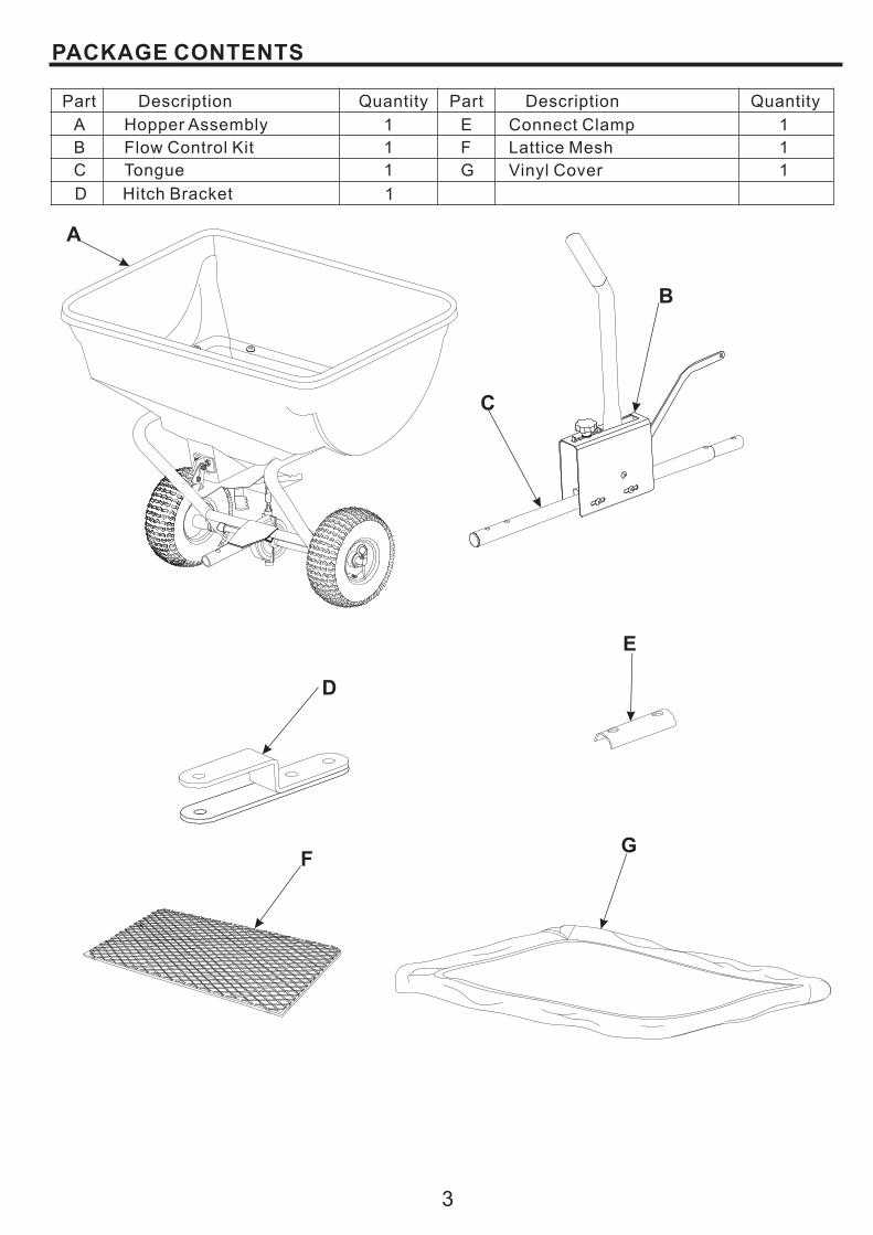
Part Description Quantity Part Description Quantity
A
B
D
F
Hopper Assembly
Flow Control Kit
Hitch Bracket
Lattice Mesh
1
1
1
1
B
D
E
C Tongue 1
C
E Connect Clamp 1
G Vinyl Cover 1
A
FG

HARDWARE CONTENTS
4
8 mm x 55 mm
Qty. 2Hex Bolt
AA
8 mm x 45 mm
Qty. 2Hex Bolt
BBHex Lock NutQty. 1
6 mmEE
PREPARATION
(Shown Actual Size)
Before assembling product, ensure all parts are included. Compare parts with package and hardware contents lists (page 3 & 4). If any part is missing or damaged, do not attempt to assemble the product. Contact customer service for replacement.
Estimated assembly time: 10 minutes
Tools Required for Assembly :
4 mm Hex Wrench (included)
11 mm& 13 mm Open-end Wrench (included)
Adjustable Wrench (not included)
Hex Lock NutQty. 4
8 mmDD
6 mm x 16 mm
Qty. 1Hex Bolt
CC16 mm x 8 mm
Qty. 1Flat Washer
FF
Clevis PinQty. 1
GG
R Clip PinQty. 1
HH
4 mm Hex WrenchQty. 1
II
(Not Shown Actual Size)
11 mm & 13 mm Open-end WrenchQty. 1
JJ

ASSEMBLY INSTRUCTIONS
1. Slide the tongue (C) into the tube on frame of hopper assembly (A). Attach the connect clip (E) to the tongue with two hex bolts (BB) and two hex lock nuts (DD).
5
1
2. Attach the crank on the flow control kit (B) to the slide bracket on hopper assembly (A) with one hex bolt (CC), one flat washer (FF) and one hex lock nut (EE).
2
3. Attach the hitch bracket (D) to the tongue (C) with two hex bolts (AA) and two hex lock nuts (DD).
3
BB
DD
E
A
C
CR
ANK
A
CC
FF
EEB
SL
IDE
B
RA
CK
ET
DD
AA
CD
6
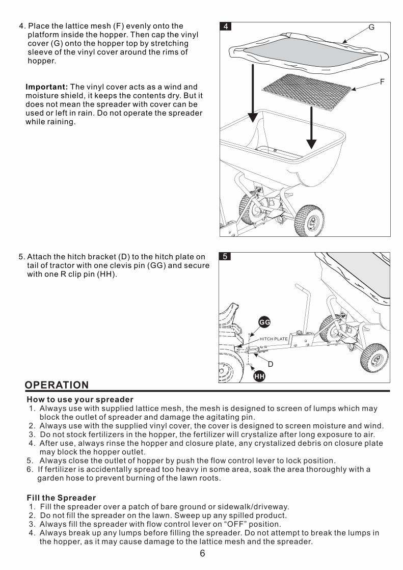
4. Place the lattice mesh (F) evenly onto the platform inside the hopper. Then cap the vinyl cover (G) onto the hopper top by stretching sleeve of the vinyl cover around the rims of hopper.
Important: The vinyl cover acts as a wind and moisture shield, it keeps the contents dry. But it does not mean the spreader with cover can be used or left in rain. Do not operate the spreader while raining.
4
5. Attach the hitch bracket (D) to the hitch plate on tail of tractor with one clevis pin (GG) and secure with one R clip pin (HH).
G
F
OPERATION
Fill the Spreader 1. Fill the spreader over a patch of bare ground or sidewalk/driveway. 2. Do not fill the spreader on the lawn. Sweep up any spilled product. 3. Always fill the spreader with flow control lever on “OFF” position. 4. Always break up any lumps before filling the spreader. Do not attempt to break the lumps in the hopper, as it may cause damage to the lattice mesh and the spreader.
How to use your spreader 1. Always use with supplied lattice mesh, the mesh is designed to screen of lumps which may block the outlet of spreader and damage the agitating pin. 2. Always use with the supplied vinyl cover, the cover is designed to screen moisture and wind. 3. Do not stock fertilizers in the hopper, the fertilizer will crystalize after long exposure to air. 4. After use, always rinse the hopper and closure plate, any crystalized debris on closure plate may block the hopper outlet.5. Always close the outlet of hopper by push the flow control lever to lock position.6. If fertilizer is accidentally spread too heavy in some area, soak the area thoroughly with a garden hose to prevent burning of the lawn roots.
5
D
GG
HH
HITCH PLATE

7
Set Flow Rate1. Determine your setting rate with the setting chart as below.
Material type Setting at 3 MPH Spread width coverage (feet)
FertilizerPowder 3-5 3-4Granular 3-5 8-10Pelleted 3-5 10-12 Organic 6-8 6-8
Grass seedFine 3-4 6-7Coarse 4-5 8-9
Important: these are general setting information, it is only for reference. The rates are affected by humidity and moisture, some minor setting adjustments may be necessary to compensate for these conditions.2. Move the flow control lever to lock (”OFF”) position.3. Loosen the wing kob to release the indicator.4. Move the indicator to desired settings.5. Tighten the wing knob to fix the position.6. When spreading, release the control lever from “OFF” position to let it rest on the indicator.
1. Move the flow control lever to lock (”OFF”) position.2. Look inside the hopper to check if the closure plate are completely closed, if there is any gap between the closure plate and the directional outlet which is under the closure plate, please follow below steps to adjust:a. Loosen the bolts on the flow control chamber.b. Move the flow control chamber back and forth till the gap is bridged, fix the position by re-tightening the bolts.
How to Adjust the Closure Plate
OF
FON
4
6
2
0
8
CLOSURE PLATE CLOSED COMPLETELY
CLOSURE PLATE
MOVE FLOW CONTROL
CHAMBER BACK AND FORTH
LOOSEN BOLTS TO ADJUST
WING KNOB INDICATOR
FLOW CONTROL LEVER
LOCK POSITION
Directional spreadings
Directional Spreadings
This spreader has a cute mechanism allows three spread patterns with a moveable outlet. the outlet can be moved to various positions for different directional spreading. Left/right spreadingsis usually used when near the sidewalks, plant beds.

A. Normal spreading (uniform spreading).
Normal pattern (uniform) spreading requires the outlet is centered the arch opening on bottom of the hopper. To get familiar with which position the directional control lever stays when the outlet is centered, you need practice before filling the hopper. Look inside empty hopper while adjusting the directional control lever, when the outlet is at the center of the arch opening on the hopper, use a marker to draw a line where the lever stays, so you know where the control lever should stay for every use of the normal spreading pattern.
B. Left-side spreading
Left side spreading requires the outlet is at the right side of the hopper opening. Move theoutlet to the right by pushing the directional control lever clockwise till it comes to the end.
C. Right-side spreading
Right-
Important notice: 1. The spreading patterns and scopes may vary with the change of towing speed and flow rate settings. Always make some slight adjustment on the outlet positions to get the best spreading effect while the condition changes.2. During spreading, you may find the spreading scope, direction is changing. The changes may come from the movement of outlet plate which is getting loose from agitating pressure inside the hopper. Stop the vehicle and close the closure plate by pushing the flow control lever to lock. Tighten the nuts securing the out let plate.
side spreading requires the outlet is at the left side of the hopper opening. Move the outlet to the right by pushing the directional control lever counter-clockwise till it comes to the end.
DIRECTIONAL CONTROL LEVER
OU
TLE
T
Normal pattern
OU
TLE
T
OUTLET
Left-side pattern
Right-side pattern
CARE AND MAINTENANCE1. Empty the hopper after each use. Do not store spreader with materials left in hopper.2. Rinse the hopper and lattice mesh, especially the closure plate and directional outlet plate and wipe dry, as debris of fertilizers may get crystalized and cause block of the closure and outlet plate to function.
4. Lubricate the alloy bushings with grease gun through the oil nipples.5. Always have the flow control lever in “ lock”position when filling the hopper or transporting.
3. Store in a clean, dry area.
OIL
NIP
PL
E
OUTLET PLATE
CLOSURE PLATE
8
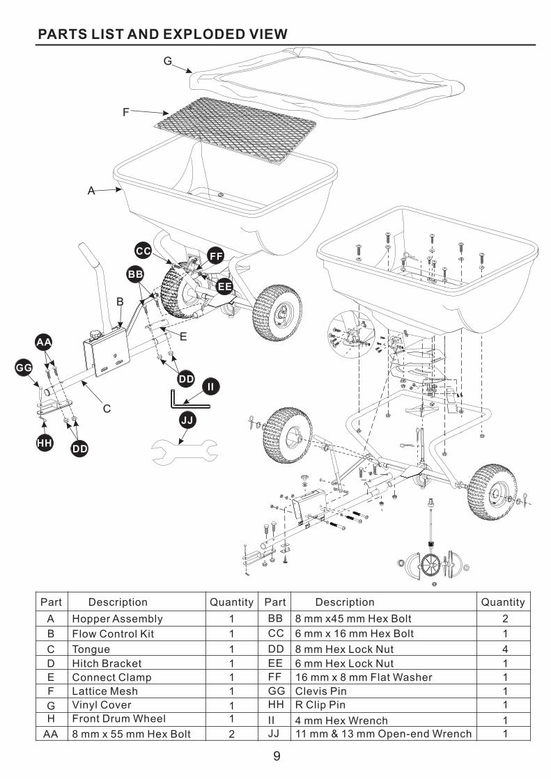
PARTS LIST AND EXPLODED VIEW
9
Hopper Assembly
Flow Control Kit
A
B
1Tongue
Hitch Bracket
E Connect Clamp
F 1Lattice Mesh
G 1Vinyl Cover
H Front Drum Wheel
AA
1
8 mm x 55 mm Hex Bolt
BB 8 mm x45 mm Hex Bolt 2
CC 16 mm x 16 mm Hex Bolt
DD
6 mm Hex Lock NutEE 1
FF 1
GG 1HH 1
II 1JJ 1
16 mm x 8 mm Flat Washer
Clevis Pin
R Clip Pin
4 mm Hex Wrench 11 mm & 13 mm Open-end Wrench
1
1
8 mm Hex Lock Nut
Part Description Quantity Part Description Quantity
1
1
2
4C
D
DD
JJ
BB
AA
DD
GG
HH
CC
EE
FF
C
II
B
E
A
F
G