2100-590(a) (2013 09)
TRANSCRIPT
Manual 2100-590APage 1 of 67
WG - SERIESCOMBINATION GAS/ELECTRIC
WALL-MOUNTMODELS:
W24G2-A W24G2-B W24G2-C W30G2-A W30G2-B W30G2-C W36G2-AW36G2-B W36G2-C W42G2-A W42G2-B W42G2-C W48G2-A W48G2-BW48G2-C W60G2-A W60G2-B W60G2-C
Manual No.: 2100-590ASupersedes: 2100-590File: Volume III, Tab 20Date: 09-20-13
Bard Manufacturing Company, Inc.Bryan, Ohio 43506
Since 1914...Moving ahead just as planned.
WARNINGREAD ALL INSTRUCTIONS CAREFULLY BEFOREBEGINNING THE INSTALLATION.
THE INSTALLATION MUST COMPLY WITH THESEINSTRUCTIONS AND THE REQUIREMENTS OF ALLGOVERNING CODES AND ORDINANCES FOR THEINSTALLATION LOCATION.
IT IS THE RESPONSIBILITY OF INSTALLER TO KNOWAND UNDERSTAND ALL OF THESE REQUIREMENTS.
FAILURE TO DO SO COULD CREATE A HAZARDRESULTING IN PROPERTY DAMAGE, BODILY INJURY,OR DEATH.
INSTALLATIONINSTRUCTIONS
Manual 2100-590APage 2 of 67
CONTENTS
Getting Other Information and Publications .............. 4W**G Series Model Nomenclature ............................ 5Ventilation Options .................................................... 5Air Conditioning Module Options ............................... 61. Important .......................................................... 102. Application ........................................................ 103. Duct Work ........................................................ 104. High Altitude Applications ................................. 115. Transportation Damage .................................... 116. Installation ........................................................ 117. Wall Mounting .................................................. 118. Mounting the Unit ............................................. 119. Clearances ....................................................... 17
10. Vent Terminal and Combustion Inlet Hood ....... 1811. Optional Vertical Venting .................................. 1812. Vent Resizing Instructions ................................ 1913. Fresh Air Intake ................................................ 1914. Condensate Drain ............................................ 1915. Wiring – Main Power ........................................ 2016. Wiring – Low Voltage Wiring ............................ 2117. Thermostats ...................................................... 2118. Gas Supply & Piping ........................................ 2619. Manifold Pressure Adjustment .......................... 27
20. Checking Gas Input Rate ......................... 27 & 2821. Standard Orifice Sizing & High
Altitude Derate .................................................. 2922. Conversion of Gas Input BTUH From High
to Low Rating ................................................... 3223. Measuring Air Temperature Rise ...................... 3224. Filters ................................................................ 3325. Compressor Control Module..................... 33 & 3426. Lighting & Shutdown Instructions ..................... 3527. Service Agency Procedures ............................. 3628. Maintaining Unit in Good Working Order .. 36 & 3729. Replacement Parts ............................................ 3730. Sequence of Operation – Heating .................... 3831. Sequence of Operation – Cooling .................... 3832. Indoor Blower Operation .................................. 3933. Pressure Service Ports ..................................... 4734. Refrigerant Charge ........................................... 4835. Fan Blade Setting Dimensions ......................... 4836. Low NOx Burner Assembly "N" Suffix
Models Only – U.S. Installations Only .............. 48Index – Wiring Diagrams ......................................... 49Wiring Diagrams ............................................. 50 – 67
Page Page
Manual 2100-590APage 3 of 67
CONTENTS
FIGURESFigure 1 Unit Dimensions ..................................... 9Figure 2 Mounting Instructions – W24-36G ....... 12Figure 2A Mounting Instructions – W42-60G ....... 13Figure 3 Combustible Clearance – W24-36G .... 14Figure 3A Combustible Clearance – W42-60G .... 14Figure 4 Wall Mounting Instructions ................... 15Figure 5 Wall Mounting Instructions ................... 15Figure 6 Common Wall Mounting Installations ... 16Figure 7 Location of Vent Terminal in Shipping .. 17Figure 8 Vent Terminal & Combustion
Air Intake .............................................. 18Figure 9 Fresh Air Damper ................................. 19Figure 10 Installation of Flexible Conduit ............. 21Figure 11 Low Voltage Wiring-No Vent Pkg. ........ 22Figure 12 Low Voltage Wiring .............................. 23Figure 13 Low Voltage Wiring-EIFM Econo. ........ 24Figure 14 Gas Pipe Connection ........................... 25Figure 15 Proper Piping Practice ......................... 26Figure 16 Access Internal Filter through
Upper Service Door .............................. 33Figure 17 Lighting & Shutdown Instruction Label . 35Figure 18 Top View of Gas Control ...................... 36Figure 19 Sequence of Operation – Electronic
Blower Control ...................................... 38Figure 20 Furnace Control Board &
Blower Control ...................................... 39Figure 21 Fan Blade ............................................. 48Figure 22 Low NOx Insert .................................... 48
TABLESTable 1 Specifications – W24-36G Models ........... 7Table 1A Specifications – W42-60G Models ........... 8Table 2 Minimum Installation Clearances ........... 17Table 3 Thermostat Wire Size ............................ 21Table 4 Wall Thermostat ..................................... 21Table 5 Length of Standard Pipe Threads .......... 26Table 6 Gas Pipe Sizes – Natural Gas ............... 26Table 7 Natural Gas Derate Capacities
For All Models ........................................ 29Table 8 Natural Gas Orifice Tables – W24-36G .. 30Table 8A Natural Gas Orifice Tables – W42-60G .. 31Table 9 Motor Speed Taps .................................. 39Table 10 W24G Indoor Blower Performance ........ 40Table 11 W30G Indoor Blower Performance ........ 41Table 12 W36G Indoor Blower Performance ........ 42Table 13 W42G Indoor Blower Performance ........ 43Table 14 W48G Indoor Blower Performance ........ 44Table 15 W60G Indoor Blower Performance ........ 45Table 16 Integrated Furnace & Blower
Control Operation ................................... 46Table 17A W24G2-W36G2
Cooling Pressure Table .......................... 47Table 17B W42G2-W60G2
Cooling Pressure Table .......................... 47Table 18 Fan Blade Dimension ............................. 48
Page Page
Manual 2100-590APage 4 of 67
Getting Other Information and Publications
FOR MORE INFORMATION, CONTACTTHESE PUBLISHERS:
ACCA Air Conditioning Contractors of America1712 New Hampshire Avenue, NWWashington, DC 20009Telephone: (202) 483-9370
ANSI American National Standards Institute11 West Street, 13th FloorNew York, NY 10036Telephone: (212) 642-4900Fax: (212) 302-1286
ASHRAE American Society of Heating Refrigerating,and Air Conditioning Engineers, Inc.1791 Tullie Circle, NE.Atlanta, GA 30329-2305Telephone: (404) 636-8400Fax: (404) 321-5478
NFPA National Fire Protection AssociationBatterymarch ParkP.O. Box 9101Quincy, MA 02269-9901Telephone: (800) 344-3555Fax: (617) 984-7057
CSA Canadian Standards Association178 Rexdale BoulevardRexdale, OntarioCanada. M9W 1R3Telephone: (416) 447-4044
BARD MANUFACTURING COMPANY, INC.BRYAN, OHIO 43506 USA
These publications can help you install the furnace. Youcan usually find these at your local library or purchasethem directly from the publisher. Be sure to consultcurrent edition of each standard.
National Fuel Gas Code ......... ANSI Z223.1 / NFPA 54
National Electrical Code ..................... ANSI / NFPA 70
Standard for the Installation ............. ANSI / NFPA 90Aof Air Conditioning and Ventilating Systems
Standard for Warm Air ..................... ANSI / NFPA 90BHeating and Air Conditioning Systems
Standard for Chimneys, ................................. NFPA 211Fireplaces, Vents, and Solid Fuel Burning Appliances
Load Calculation for ............................ ACCA Manual JResidential Winter and Summer Air Conditioning
Duct Design for Residential ............... ACCA Manual DWinter and Winter Air Conditioning and EquipmentSelection
Canadian Electrical Code ............................. CSA C22.1
Canadian Installation Code……………CAN/CGA B149
Manual 2100-590APage 5 of 67
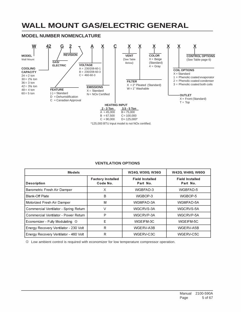
W 42 G 2 – A X C X X X X X X
WALL MOUNT GAS/ELECTRIC GENERALMODEL NUMBER NOMENCLATURE
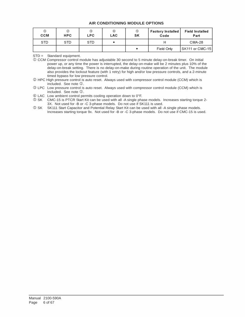
1 Low ambient control is required with economizer for low temperature compressor operation.
VENTILATION OPTIONS
sledoM G63W,G03W,G42W G06W,G84W,G24W
noitpircseD
dellatsnIyrotcaF
.oNedoC
dellatsnIdleiF
.oNtraP
dellatsnIdleiF
.oNtraP
repmaDriAhserFcirtemoraB X 3-DAFBGW 5-DAFBGW
etalPffO-knalB B 3-POBGW 5-POBGW
repmaDriAhserFdezirotoM M A3-DAFMGW A5-DAFMGW
nruteRgnirpS-rotalitneVlaicremmoC V A3-SVRCGW A5-SVRCGW
nruteRrewoP-rotalitneVlaicremmoC P A3-PVRCGW A5-PVRCGW
gnitaludoMylluF-rezimonocE 1 E C3-MFIEGW C5-MFIEGW
tloV032-rotalitneVyrevoceRygrenE R B3A-VREGW B5A-VREGW
tloV064-rotalitneVyrevoceRygrenE R C3C-VREGW C5C-VREGW
MODELWall Mount
CONTROL OPTIONS(See Table page 6)
VENT(See Table
Below)
COOLINGCAPACITY24 = 2 ton30 = 2½ ton36 = 3 ton42 = 3½ ton48 = 4 ton60 = 5 ton OUTLET
X = Front (Standard)T = Top
COIL OPTIONSX = Standard1 = Phenolic coated evaporator2 = Phenolic coated condenser3 = Phenolic coated both coils
COLORX = Beige(Standard)4 = Gray
FILTERX = 2" Pleated (Standard)W = 1" Washable
VOLTAGEA = 230/208-60-1B = 230/208-60-3C = 460-60-3
REVISION
FEATURE(-) = StandardD = DehumidificationC = Canadian Approval
EMISSIONSX = StandardN = NOx Certified
*125,000 BTU input model is not NOx certified.
HEATING INPUT 2 - 3 Ton 3.5 - 5 TonA = 45,000 B= 75,000B = 67,500 C= 100,000C = 90,000 D= 125,000*
GAS/ELECTRIC
Manual 2100-590APage 6 of 67
AIR CONDITIONING MODULE OPTIONS
STD = Standard equipment.1 CCM Compressor control module has adjustable 30 second to 5 minute delay-on-break timer. On initial
power up, or any time the power is interrupted, the delay-on-make will be 2 minutes plus 10% of thedelay-on-break setting. There is no delay-on-make during routine operation of the unit. The modulealso provides the lockout feature (with 1 retry) for high and/or low pressure controls, and a 2-minutetimed bypass for low pressure control.
2 HPC High pressure control is auto reset. Always used with compressor control module (CCM) which isincluded. See note 1.
3 LPC Low pressure control is auto reset. Always used with compressor control module (CCM) which isincluded. See note 1.
4 LAC Low ambient control permits cooling operation down to 0°F.5 SK CMC-15 is PTCR Start Kit can be used with all -A single phase models. Increases starting torque 2-
3X. Not used for -B or -C 3-phase models. Do not use if SK111 is used.5 SK SK111 Start Capacitor and Potential Relay Start Kit can be used with all -A single phase models.
Increases starting torque 9x. Not used for -B or -C 3-phase models. Do not use if CMC-15 is used.
1
MCC
2
CPH
3
CPL
4
CAL
5
KS
dellatsnIyrotcaF
edoC
dellatsnIdleiF
traP
DTS DTS DTS � H 82-AMC
� ylnOdleiF 51-CMCro111KS
Manual 2100-590APage 7 of 67
TAB
LE 1
SP
EC
IFIC
ATI
ON
SW
24G
, W30
G A
ND
W36
G M
OD
ELS
* 7
5 de
gree
C C
oppe
r wire
siz
e**
Max
imum
tim
e de
lay
fuse
or H
AC
R T
ype
circ
uit b
reak
er
ledo
MA-
2G42
WB-
2G42
WC-
2G42
WA-
2G03
WB-
2G03
WC-
2G03
WA-
2G63
WB-
2G63
WC-
2G63
W
ZH06
–gnit
aRlacirt
cel
E1-
802/
032
3-802/
032
3-064
1-802/
032
3-802/
032
3-064
1-802/
032
3-802/
032
3-064
egnaR
egatl
oV
gnit
arepO
352-
791
352-
791
605-
414
352-
791
352-
791
605-
414
352-
791
352-
791
605-
414
yticap
mAtiucri
Cmu
mini
M12
61
932
71
01
82
52
11
**.x
aMrekaer
Btiucri
Cro
esuFyaleD
03
52
51
53
52
51
54
04
51
rosser
pmo
C
stloV
1-802/
032
3-802/
032
3-064
1-802/
032
3-802/
032
3-064
1-802/
032
3-802/
032
3-064
sp
mA
daoL
det
aR
9.01/
9.9
1.7/
4.6
9.3
9.21/
8.11
2.8/
5.7
7.4
7.61/
3.51
6.41/
3.31
1.5
tnerr
uC
noit
celeStiucri
Chcnar
B8.
21
3.8
1.5
1.41
0.9
6.5
9.71
6.51
0.6
sp
mArot
oR
kcoL
46
85
82
77
17
83
211
011
44
rot
alitneV
yrevoce
Rygr
enE
stloV
1-06-
802/
032
1-06-
802/
032
1-06-
802/
032
)sr
oto
m-3(
sp
mA
daoLlluF
2.2
2.2
2.2
rot
oM
naF
rewopesr
oH
5/1
5/1
5/1
stloV
1-06-
802/
032
1-06-
064
1-06-
802/
032
1-06-
064
1-06-
802/
032
1-06-
064
sp
mA
daoLlluF
5.1
8.0
5.1
8.0
5.1
8.0
MFC
0042
0042
0042
rot
oMrewol
B
rewopesr
oH
4/1
4/1
4/1
stloV
1-06-
802/
032
1-06-
064
1-06-
802/
032
1-06-
064
1-06-
802/
032
1-06-
064
sp
mA
daoLlluF
8.1
8.0
2.2
1.1
2.2
1.1
Manual 2100-590APage 8 of 67
* 7
5 de
gree
C C
oppe
r wire
siz
e**
Max
imum
tim
e de
lay
fuse
or H
AC
R T
ype
circ
uit b
reak
er
TAB
LE 1
AS
PE
CIF
ICA
TIO
NS
W42
G, W
48G
AN
D W
60G
MO
DE
LS
ledo
MA-
2G24
WB-
2G24
WC-
2G24
WA-
2G84
WB-
2G84
WC-
2G84
WA-
2G06
WB-
2G06
WC-
2G06
W
ZH06
–gnit
aRlacirt
cel
E1-
802/
032
3-802/
032
3-064
1-802/
032
3-802/
032
3-064
1-802/
032
3-802/
032
3-064
egnaR
egatl
oV
gnit
arepO
352-
791
352-
791
605-
414
352-
791
352-
791
605-
414
352-
791
352-
791
605-
414
yticap
mAtiucri
Cmu
mini
M13
32
11
43
52
21
04
82
41
**.x
aMrekaer
Btiucri
Cro
esuFyaleD
05
53
51
05
53
51
06
04
02
rosser
pmo
C
stloV
1-802/
032
3-802/
032
3-064
1-802/
032
3-802/
032
3-064
1-802/
032
3-802/
032
3-064
sp
mA
daoL
det
aR
5.71/
5.51
5.11/
2.01
8.4
4.12/
3.91
5.41/
1.31
4.6
7.42/
6.12
7.41/
8.21
8.7
tnerr
uC
noit
celeStiucri
Chcnar
B9.
91
1.31
1.6
4.12
5.41
4.6
3.62
6.51
8.7
sp
mArot
oR
kcoL
901
1.38
14
531
89
55
431
011
25
rot
alitneV
yrevoce
Rygr
enE
stloV
1-06-
802/
032
1-06-
802/
032
1-06-
802/
032
)sr
oto
m-3(
sp
mA
daoLlluF
2.2
2.2
2.2
rot
oM
naF
rewopesr
oH
3/1
3/1
3/1
stloV
1-06-
802/
032
1-06-
064
1-06-
802/
032
1-06-
064
1-06-
802/
032
1-06-
064
sp
mA
daoLlluF
5.2
3.1
5.2
3.1
5.2
3.1
MFC
0503
0503
0503
rot
oMrewol
B
rewopesr
oH
3/1
3/1
3/1
stloV
1-06-
802/
032
1-06-
064
1-06-
802/
032
1-06-
064
1-06-
802/
032
1-06-
064
sp
mA
daoLlluF
4.3
5.1
4.3
5.1
4.3
5.1
Manual 2100-590APage 9 of 67
F G
N
P
D
DD
FF
GG
HH A
M
I C KJL
H
R S S S S S T
VYAAX
U Z
CC
BB
BE
EO
E
B
II Q
W
CO
MB
US
TIO
NA
IR IN
TA
KE
CO
NT
RO
L
RIG
HT
SID
E
EN
TR
AN
CE
S
GA
S
RE
TU
RN
OP
EN
ING
4 D
EG
. PIT
CH
IN T
OP
PA
NE
L D
OO
R
DO
OR
LOW
VO
LTA
GE
SU
PP
LY O
PE
NIN
G
PA
NE
L
BA
CK
DIS
CO
NN
EC
T A
CC
ES
S
VE
ST
IBU
LE
PA
NE
L (L
OC
KA
BLE
)
CO
ND
EN
SE
R A
IR IN
LET
SC
ON
DE
NS
ER
VE
NT
OP
TIO
NA
IR O
UT
LET
AIR
EX
HA
US
TC
OM
BU
ST
ION
EN
TR
AN
CE
S
FR
ON
T
CIR
CU
IT B
RE
AK
ER
/
MIS
-323
9
HIG
H V
OLT
AG
E E
NT
RA
NC
ES
FR
ON
T D
OO
R
FIL
TE
RS
ER
VIC
ED
OO
R
UN
ITA
BC
DE
FG
HI
JK
LM
NO
PQ
R
W24G
-W30G
-W36G
7.8
827.8
813.8
824.2
540
25.6
381.6
327.3
827.5
39.2
55.8
8
W42G
-W48G
-W60G
9.8
829.8
815.8
827.2
543.8
131.6
387.5
33.3
828.7
542.8
83.7
5
UN
ITS
TU
VW
XY
ZA
AB
BC
CD
DE
EF
FG
GH
HII
W24G
-W30G
-W36G
12 -
7 H
OLE
S2.8
822.9
38
17.8
44.4
411.4
49
36.2
52
0.3
8
W42G
-W48G
-W60G
16 -
6 H
OLE
S3.8
824.9
42
17.3
48.4
412.1
910
40.2
52.7
50.4
41.2
57.2
51.1
33.7
52.2
53.2
5
15.3
14.5
2.5
14.8
830
14.1
215.4
4
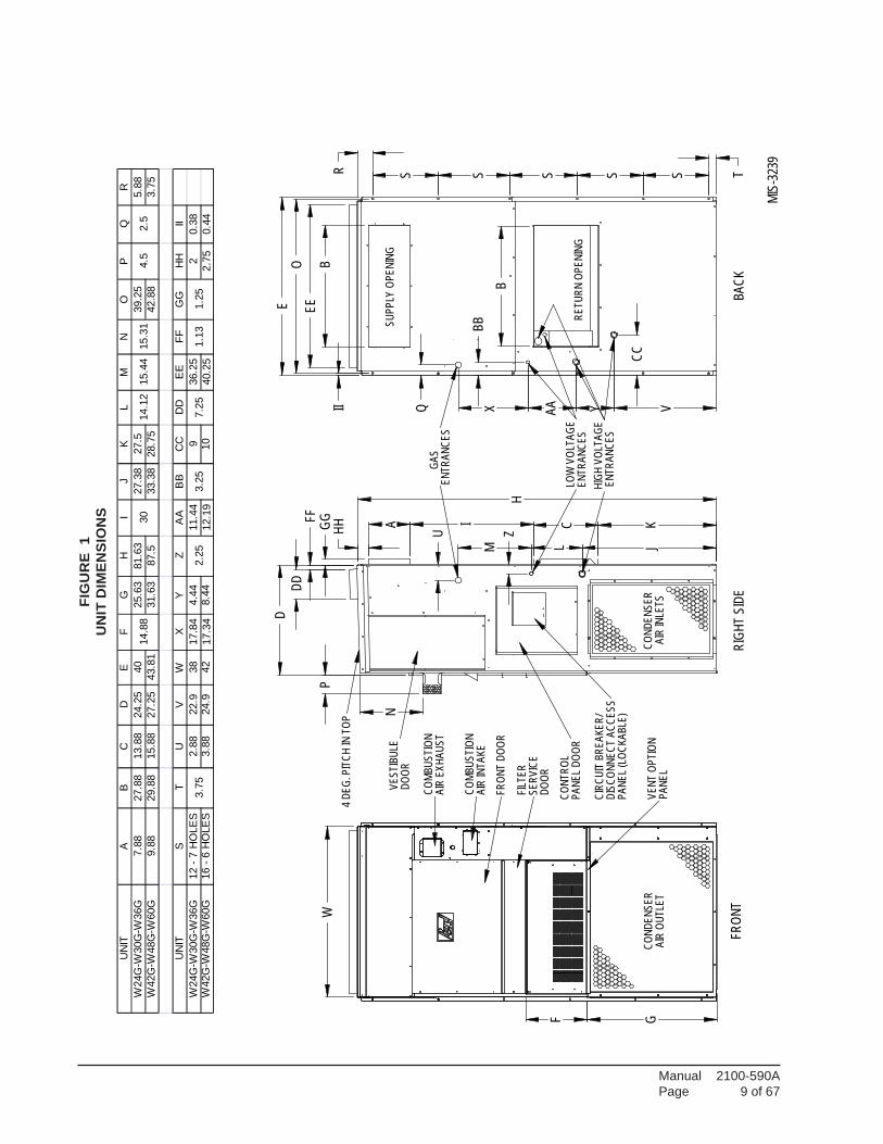
FIG
UR
E 1
UN
IT D
IME
NS
ION
S
Manual 2100-590APage 10 of 67
1. IMPORTANTThe equipment covered in this manual is to be installed bytrained, experienced service and installation technicians.All duct work or portions thereof not in the conditionedspace should be properly insulated in order to both conserveenergy and prevent condensation or moisture damage.
2. APPLICATIONThis is a fan-assisted forced air gas furnace with electricair conditioning for outdoor installation. A fan-assistedfurnace is equipped with an integral mechanical meansto draw products of combustion through the combustionchamber and heat exchanger. The furnace installationmust conform with local building codes and ordinancesor, in their absence, with the National Fuel Gas CodeANSI Z223.1 or CAN/CGA-B149.1, latest edition, andthe National Electrical Code ANSI/NFPA-7 or CSAC22.1, latest edition. It is the personal responsibilityand obligation of the purchaser to contact a qualifiedinstaller to assure that installation is adequate and is inconformance with governing codes and ordinances.
3. DUCT WORKThe unit is designed for use with or without duct work.See Warning on Page 10. Flanges are provided forattaching the supply and return ducts. Theseinstructions explain the recommended method to installthe air cooled self-contained electric air conditioningand gas heating unit and the electrical wiringconnections and gas piping to the unit. The refrigerantsystem is completely assembled and charged. Allinternal wiring is complete.
These instructions and any instructions packaged with anyseparate equipment required to make up the entire heating/cooling system should be carefully read before beginningthe installation. Note particularly “Starting Procedure”and any tags and/or labels attached to the equipment.
All duct work, supply and return, must be properly sizedfor the design airflow requirement of the equipment.Air Conditioning Contractors of America (ACCA) is anexcellent guide to proper sizing.
Refer to Tables 10, 11, 12, 13, 14 and 15 in this Manualfor maximum static pressure available for duct design.
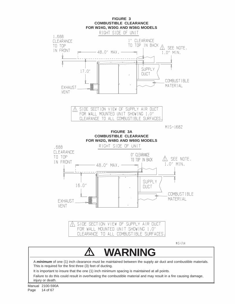
See Figure 3 and clearance information in Section 9 andTable 2 for additional information.
Design the duct work according to methods given by theAir Conditioning Contractors of America (ACCA).When duct runs through unheated spaces, it should beinsulated with a minimum of one-inch of insulation.Use insulation with a vapor barrier on the outside of theinsulation. Flexible joints should be used to connect theduct work to the equipment in order to keep the noisetransmission to a minimum.
A one-inch clearance to combustible material for thefirst three feet of duct attached to the outlet air frame isrequired. See Wall Mounting Instructions and Figures2, 2A, 3 and 3A for further details.
Ducts through the walls must be insulated and all joints tapedor sealed to prevent air or moisture entering the wall cavity.
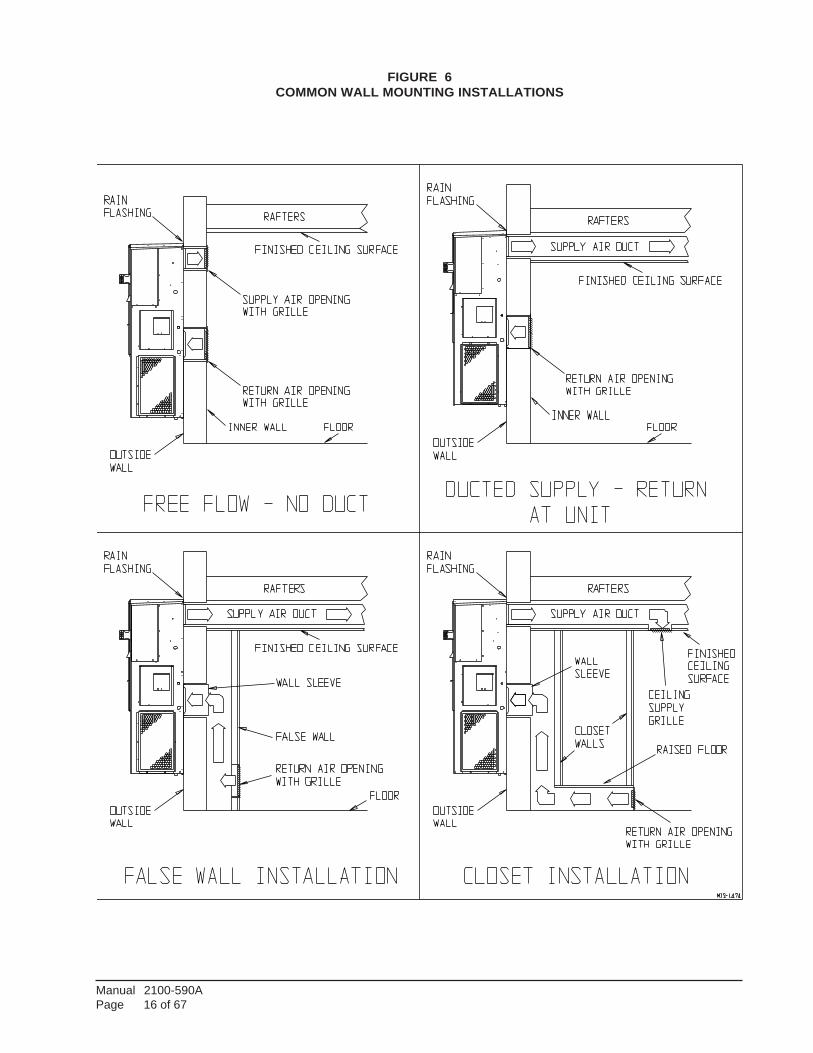
Some installations may not require any return air duct.A metallic return air grille is required with installationsnot requiring a return air duct. The spacing betweenlouvers on the grille shall not be larger than 5/8 inch.
Any grille that meets with the 5/8 inch louver criteria maybe used. It is recommended that Bard Return Air Grille orReturn Filter Grille be installed when no return duct is used.Contact distributor or factory for ordering information. Ifusing a return air filter grille, filters must be of sufficientsize to allow a maximum velocity of 400 fpm.
NOTE: If no return air duct is used, applicableinstallation codes may limit this cabinet toinstallation only in a single story structure.
WARNINGIn all cases, there must be a metal duct
connection made to the supply air flange, and aone inch clearance to combustibles must bemaintained to this duct connection.
For free blow applications, a metal sleeve mustbe used in the wall opening itself, againmaintaining a one inch clearance to combustibles.
Failure to use the sheet metal can cause fireresulting in property damage, injury, or death.
CAUTIONDuring the initial firing of the burners there will probably be some amount of smoke issued to thecirculating air stream as the result of residual oil burning off of the heat exchanger tubes. This oilis required during the forming process of the stainless steel heat exchanger tubes to facilitate thebending. OSHA or the National Toxicology Program does not list the oil as a carcinogen. In vaporform this may be irritating to the eyes or could cause headaches. This is a one-time occurrence,and ventilation of the space may be required depending upon the space being conditioned.
Manual 2100-590APage 11 of 67
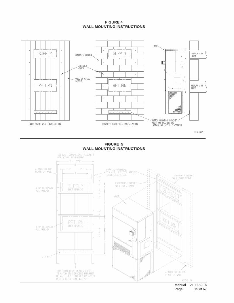
8. MOUNTING THE UNIT1. These units are secured by wall mounting
brackets which secure the unit to the outsidewall surface at both sides. A bottom mountingbracket is provided for ease of installation butis not required.
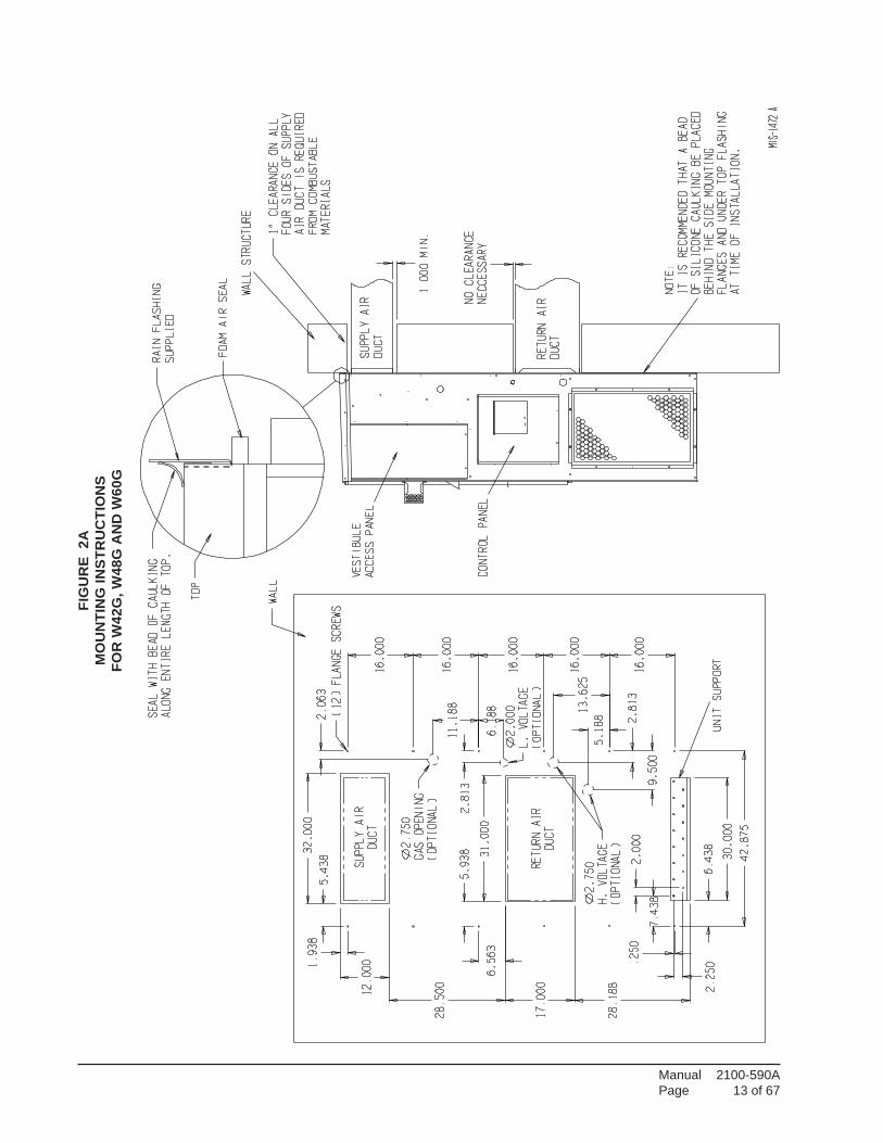
2. The W42G, W48G and W60G models aresuitable for 0 inch clearance on the installationmounting wall and to the top. For all models thesupply air duct flange and the first 3 feet ofsupply air duct require a minimum of 1-inchclearance to combustible material. The W24G,W30G and W36G models are suitable for 0 inchclearance on the installation mounting wall, butrequire 1-inch clearance to the top if combustiblematerial overhang projects above the unit. SeeFigure 3 and 3A. If a combustible wall, use aminimum of Figure 1 “A” dimension plus 2inches and “B” dimension plus 2 inches. SeeFigures 4 and 5 for details.
3. Locate and mark lag bolt locations and bottommounting bracket location.
4. Mount bottom mounting bracket.5. Hook top rain flashing under back bend of top.
Top rain flashing is shipped secured to the rightside of the back.
6. Position unit in opening and secure with 5/16lag bolts; use 7/8 inch diameter flat washers onthe lag bolts. Use lag bolts long enough tosupport the unit’s weight when mounted to thestructure. This length may be dependant on thetype of construction.
7. Secure rain flashing to wall and caulk acrossentire length of top. See Figure 3.
8. On side-by-side installations, maintain aminimum of 20 inches clearance on right sideto allow access to control panel and burnercompartment, and to allow proper airflow to theoutdoor coil. Additional clearance may berequired to meet local or national codes.
4. HIGH ALTITUDE APPLICATIONSRatings of gas utilization equipment are based on sealevel operation and need not be changed for operation atelevations up to 6,000 feet. For operation at elevationsabove 6,000 feet and in the absence of specificrecommendations from the local authority havingjurisdiction, equipment ratings shall be reduced asspecified in Section 21.
5. TRANSPORTATION DAMAGEAll units are packed securely in shipping container. Allunits should be carefully inspected upon arrival fordamage. In the event of damage, the consignee should:1. Note on delivery receipt of any damage to container.2. Notify carrier promptly, and request an inspection.3. In case of concealed damage, the carrier must be
notified as soon as possible within 15 days afterdelivery.
4. Claims for any damage, apparent or concealed,should be filed with the carrier, using the followingsupporting documents:
A. Original Bill of Lading, certified copy, orindemnity bond.
B. Original paid freight bill of indemnity in lieu thereof.C. Original invoice or certified copy thereof showing
trade and other discounts or deductions.D. Copy of the inspection report issued by
carrier’s representative at the time damage isreported to carrier.
6. INSTALLATIONSize of unit for proposed installation should be based onheat loss/heat gain calculations made according tomethods of Air Conditioning Contractors of America(ACCA). The air duct should be installed in accordancewith the Standards of the National Fire ProtectionAssociation for the Installation of Air Conditioning andVentilating Systems of Other Than Residence Type,NFPA No. 90A, and Residence Type Warm Air Heatingand Air Conditioning Systems, NFPA No. 90B. Wherelocal regulations are at a variance with instructions,installer should adhere to local codes.
7. WALL MOUNTING INFORMATION1. Two holes for the supply and return air
openings must be cut through the wall asdetailed in Figure 4.
2. On wood-frame walls, the wall constructionmust be strong and rigid enough to carry theweight of the unit without transmitting any unitvibration.
3. Concrete block walls must be thoroughlyinspected to insure that they are capable ofcarrying the weight of the installed unit.
CAUTIONIf the bottom bracket is used, be certain thebracket is secured to the outside wall surfacein a way sufficient to support the entire weightof the unit during installation until sidemounting brackets are secured.
WARNINGFailure to provide the one inch clearancebetween the supply duct and a combustiblesurface for the first three feet of duct canresult in fire causing damage, injury or death.
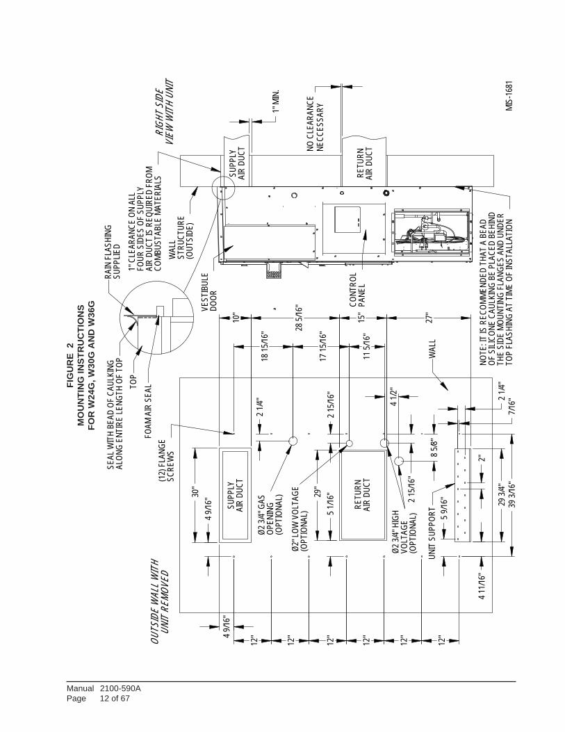
Manual 2100-590APage 12 of 67
FIG
UR
E 2
MO
UN
TIN
G IN
STR
UC
TIO
NS
FOR
W24
G, W
30G
AN
D W
36G
39 3
/16"
29 3
/4"
4 11
/16"
12"
12"
12"
12"
12"
12"
2"
2 1/
4"
10"
28 5
/16"
15"
27"
17 1
5/16
"
11 5
/16"
8 5/
8"
2 15
/16"
2 1/
4"
30"
29"
5 1/
16"
7/16
"
5 9/
16"
4 9/
16"
4 1/
2"
2 15
/16"
18 1
5/16
"
4 9/
16"
SU
PP
LYA
IR D
UC
T
RE
TU
RN
AIR
DU
CT
Ø2
3/4"
GA
S
OP
EN
ING
(OP
TIO
NA
L)
Ø2
3/4"
HIG
HV
OLT
AG
E(O
PT
ION
AL)
Ø2"
LO
W V
OLT
AG
E(O
PT
ION
AL)
(12)
FLA
NG
ES
CR
EW
S
UN
IT S
UP
PO
RT
1" M
IN.
NE
CC
ES
SA
RY
NO
CLE
AR
AN
CE
SU
PP
LYA
IR D
UC
T
RE
TU
RN
AIR
DU
CT
CO
NT
RO
L P
AN
EL
VE
ST
IBU
LED
OO
R
WA
LLS
TR
UC
TU
RE
(OU
TS
IDE
)
1" C
LEA
RA
NC
E O
N A
LLF
OU
R S
IDE
S O
F S
UP
PLY
AIR
DU
CT
IS R
EQ
UIR
ED
FR
OM
CO
MB
US
TA
BLE
MA
TE
RIA
LS
NO
TE
: IT
IS R
EC
OM
ME
ND
ED
TH
AT
A B
EA
DO
F S
ILIC
ON
E C
AU
LKIN
G B
E P
LAC
ED
BE
HIN
DT
HE
SID
E M
OU
NT
ING
FLA
NG
ES
AN
D U
ND
ER
TO
P F
LAS
HIN
G A
T T
IME
OF
INS
TA
LLA
TIO
N
RIG
HT
SID
EV
IEW
WIT
H U
NIT
OU
TS
IDE
WA
LL W
ITH
UN
IT R
EM
OV
ED
RA
IN F
LAS
HIN
GS
UP
PLI
ED
SE
AL
WIT
H B
EA
D O
F C
AU
LKIN
G
ALO
NG
EN
TIR
E L
EN
GT
H O
F T
OP
TO
P
FO
AM
AIR
SE
AL
WA
LL
MIS
-168
1
Manual 2100-590APage 13 of 67
FIG
UR
E 2
AM
OU
NTI
NG
INS
TRU
CTI
ON
SFO
R W
42G
, W48
G A
ND
W60
G
Manual 2100-590APage 14 of 67
FIGURE 3COMBUSTIBLE CLEARANCE
FOR W24G, W30G AND W36G MODELS
FIGURE 3ACOMBUSTIBLE CLEARANCE
FOR W42G, W48G AND W60G MODELS
WARNINGA minimum of one (1) inch clearance must be maintained between the supply air duct and combustible materials.This is required for the first three (3) feet of ducting.It is important to insure that the one (1) inch minimum spacing is maintained at all points.Failure to do this could result in overheating the combustible material and may result in a fire causing damage,injury or death.
Manual 2100-590APage 15 of 67
FIGURE 4WALL MOUNTING INSTRUCTIONS
FIGURE 5WALL MOUNTING INSTRUCTIONS
Manual 2100-590APage 16 of 67
FIGURE 6COMMON WALL MOUNTING INSTALLATIONS
Manual 2100-590APage 17 of 67
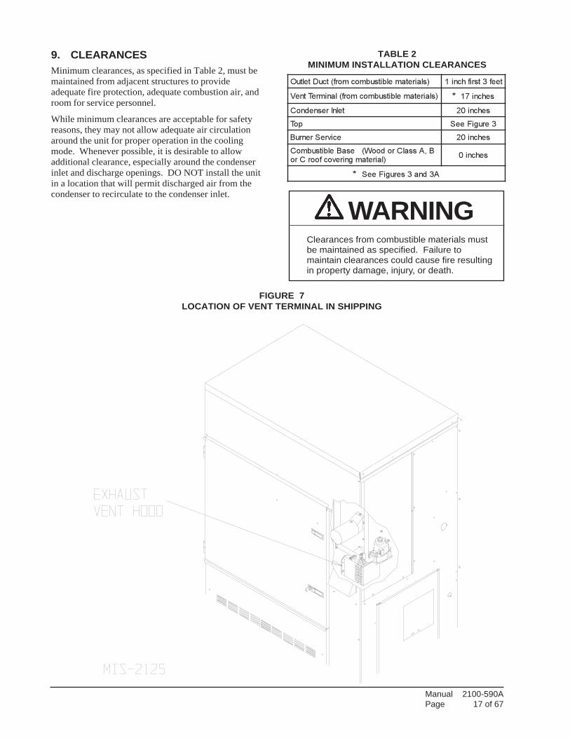
9. CLEARANCESMinimum clearances, as specified in Table 2, must bemaintained from adjacent structures to provideadequate fire protection, adequate combustion air, androom for service personnel.
While minimum clearances are acceptable for safetyreasons, they may not allow adequate air circulationaround the unit for proper operation in the coolingmode. Whenever possible, it is desirable to allowadditional clearance, especially around the condenserinlet and discharge openings. DO NOT install the unitin a location that will permit discharged air from thecondenser to recirculate to the condenser inlet.
TABLE 2MINIMUM INSTALLATION CLEARANCES
)slairetamelbitsubmocmorf(tcuDteltuO teef3tsrifhcni1
)slairetamelbitsubmocmorf(lanimreTtneV * sehcni71
telnIresnednoC sehcni02
poT 3erugiFeeS
ecivreSrenruB sehcni02
B,AssalCrodooW(esaBelbitsubmoC)lairetamgnirevocfoorCro
sehcni0
* A3dna3serugiFeeS
FIGURE 7LOCATION OF VENT TERMINAL IN SHIPPING
WARNINGClearances from combustible materials mustbe maintained as specified. Failure tomaintain clearances could cause fire resultingin property damage, injury, or death.
Manual 2100-590APage 18 of 67
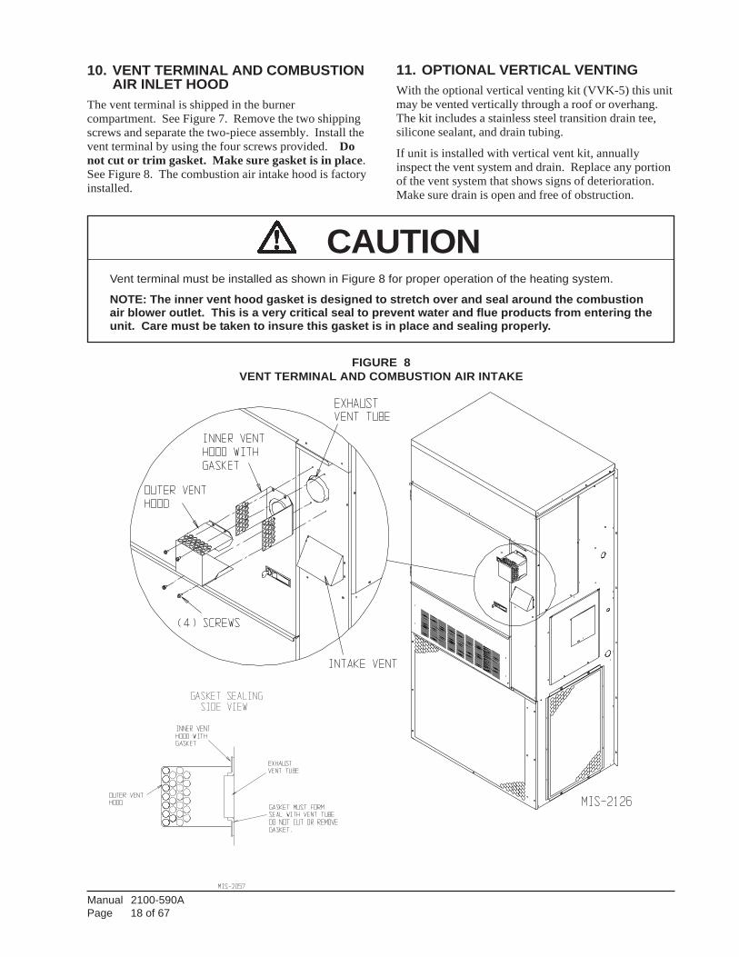
10. VENT TERMINAL AND COMBUSTIONAIR INLET HOOD
The vent terminal is shipped in the burnercompartment. See Figure 7. Remove the two shippingscrews and separate the two-piece assembly. Install thevent terminal by using the four screws provided. Donot cut or trim gasket. Make sure gasket is in place.See Figure 8. The combustion air intake hood is factoryinstalled.
11. OPTIONAL VERTICAL VENTINGWith the optional vertical venting kit (VVK-5) this unitmay be vented vertically through a roof or overhang.The kit includes a stainless steel transition drain tee,silicone sealant, and drain tubing.
If unit is installed with vertical vent kit, annuallyinspect the vent system and drain. Replace any portionof the vent system that shows signs of deterioration.Make sure drain is open and free of obstruction.
FIGURE 8VENT TERMINAL AND COMBUSTION AIR INTAKE
CAUTIONVent terminal must be installed as shown in Figure 8 for proper operation of the heating system.
NOTE: The inner vent hood gasket is designed to stretch over and seal around the combustionair blower outlet. This is a very critical seal to prevent water and flue products from entering theunit. Care must be taken to insure this gasket is in place and sealing properly.
Manual 2100-590APage 19 of 67
12. VENT RESIZING INSTRUCTIONSWhen an existing furnace is removed from a ventingsystem servicing other appliances, the venting system islikely to be too large to properly vent the remainingattached appliances.
The following steps shall be followed with each of theappliances remaining connected to the common ventingsystem, placed in operation one at a time while theother appliances remaining connected to the commonventing system are not in operation.
1. Seal any unused openings in the venting system.
2. Inspect the venting system for proper size andhorizontal pitch, as required in the National Fuel Gascode, ANSI Z223.1 or the CAN/CGA B149Installation Codes and these instructions. Determinethat there is no blockage or restriction, leakage,corrosion and other deficiencies which could causean unsafe condition.
3. In so far as is practical, close all building doors andwindows and all doors between the space in whichthe appliance(s) connected to the venting system arelocated and other spaces of the building. Turn onclothes dryers and any appliances not connected tothe venting system. Turn on any exhaust fans, suchas range hoods and bathroom exhausts, so they willoperate at maximum speed. Do not operate asummer exhaust fan. Close fireplace dampers.
4. Follow the lighting instructions. Place the appliancebeing inspected in operation. Adjust thermostat soappliance shall operate continuously.
5. Test for draft hood equipped appliance spillage at thedraft hood relief opening after 5 minutes of mainburner operation. Use the flame of a match orcandle.
6. After it has been determined that each applianceconnected to the venting system properly vents whentested as outlined above, return doors, windows,exhaust fans, fireplace dampers and any other gas-burning appliances to their previous conditions ofuse.
7. If improper venting is observed during any of theabove tests, the venting system must be corrected.
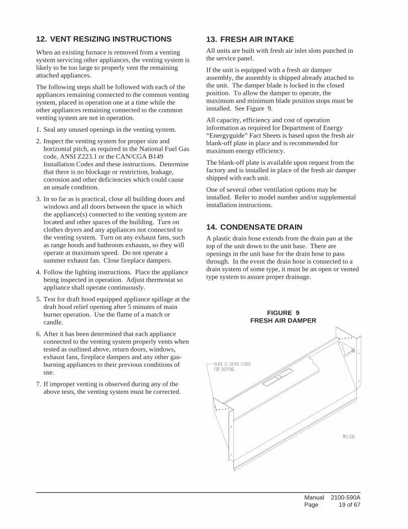
13. FRESH AIR INTAKEAll units are built with fresh air inlet slots punched inthe service panel.
If the unit is equipped with a fresh air damperassembly, the assembly is shipped already attached tothe unit. The damper blade is locked in the closedposition. To allow the damper to operate, themaximum and minimum blade position stops must beinstalled. See Figure 9.
All capacity, efficiency and cost of operationinformation as required for Department of Energy“Energyguide” Fact Sheets is based upon the fresh airblank-off plate in place and is recommended formaximum energy efficiency.
The blank-off plate is available upon request from thefactory and is installed in place of the fresh air dampershipped with each unit.
One of several other ventilation options may beinstalled. Refer to model number and/or supplementalinstallation instructions.
14. CONDENSATE DRAINA plastic drain hose extends from the drain pan at thetop of the unit down to the unit base. There areopenings in the unit base for the drain hose to passthrough. In the event the drain hose is connected to adrain system of some type, it must be an open or ventedtype system to assure proper drainage.
FIGURE 9FRESH AIR DAMPER
Manual 2100-590APage 20 of 67
ELECTRICAL GROUNDING
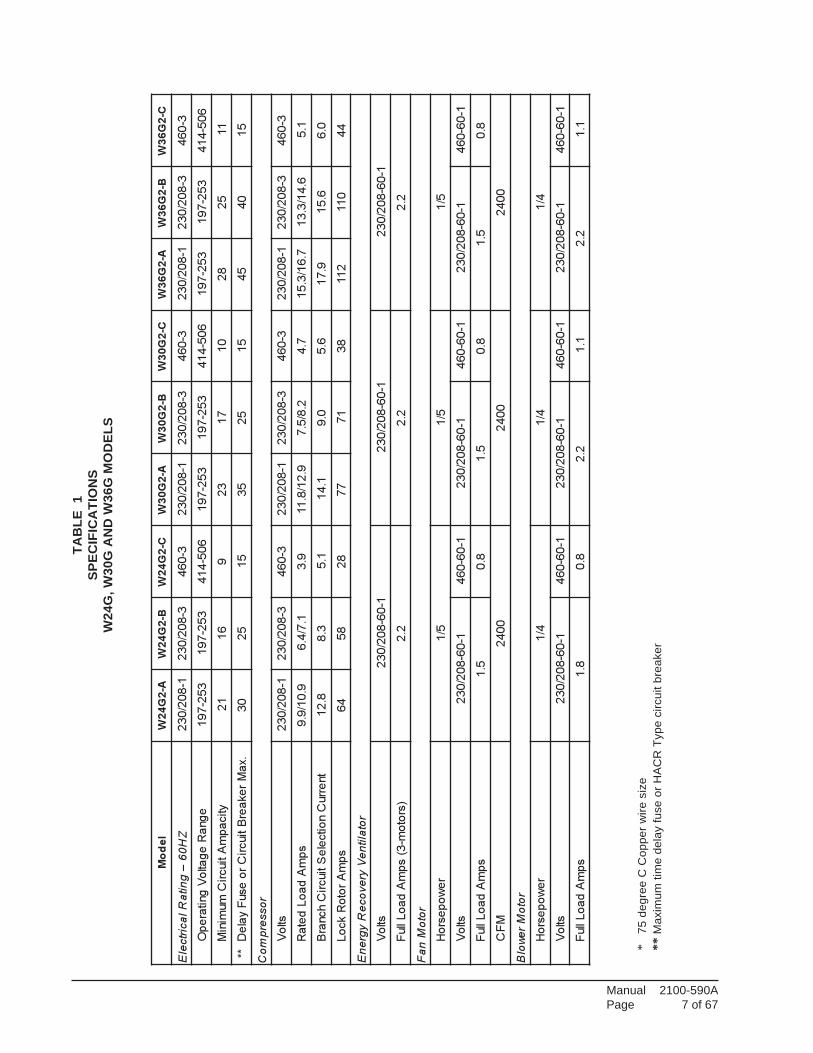
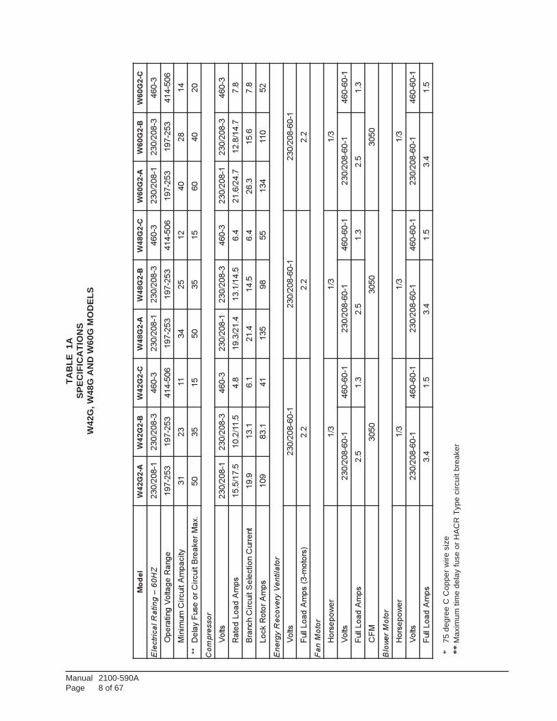
When installed, the furnace must be electricallygrounded in accordance with local codes or in theabsence of local codes, with the National ElectricalCode, ANSI/NFPA 70, or Canadian Electrical Code,CSA22.1, latest edition. Use a copper wire from greenground wire on the furnace to a grounded connection inthe service panel or a properly driven and electricallygrounded ground rod. See Tables 1 & 1A for properground wire size.
FIELD INSTALLED EQUIPMENTWiring to be done in the field between the furnace anddevices not attached to the furnace, or between separatedevices which are field installed and located, shallconform with the temperature limitation for Type Twire {63 degrees F rise (36 degrees C)} when installedin accordance with the manufacturer’s instructions.
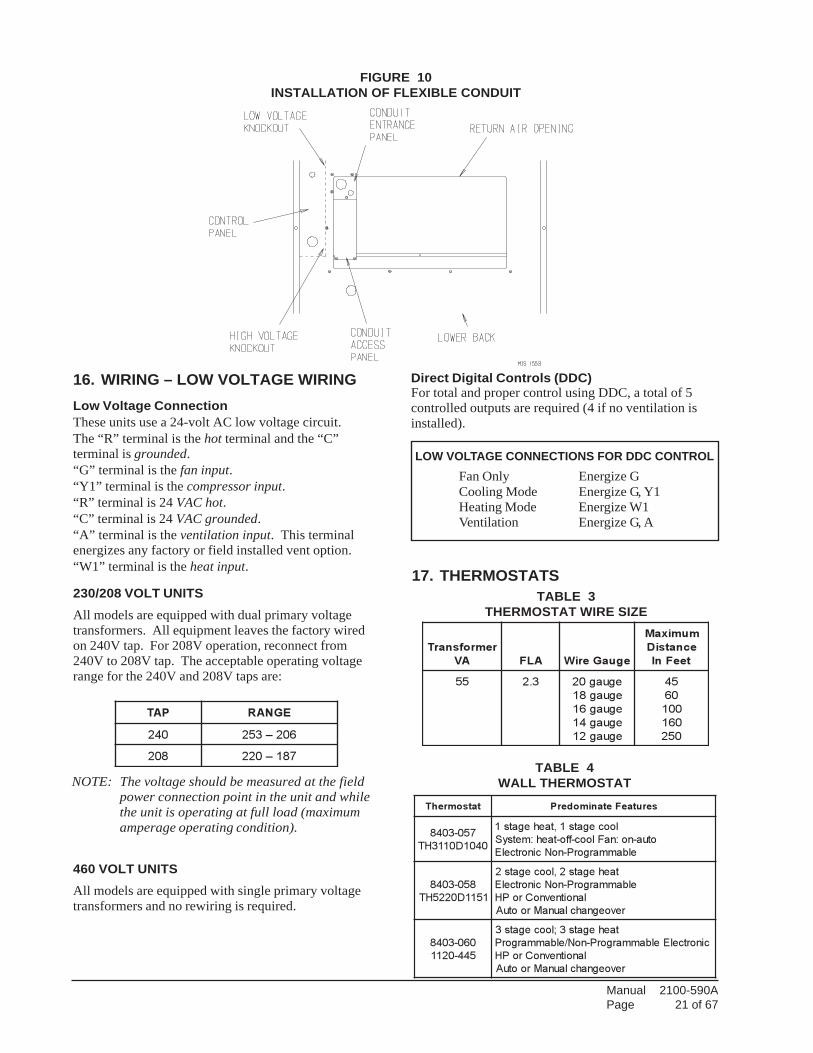
INSTALLATION OF FLEXIBLE CONDUITTHROUGH RETURN AIR OPENINGNOTE: To allow proper clearance between the
control panel and any vent options, 90°conduit fittings must be used on the back ofthe control panel.
INSTALLING CONDUIT (See Figure 10.)
1. Remove conduit access panel if required to gainaccess to area behind control panel.
2. Remove low voltage and high voltage knockoutslocated in rear of control panel.
3. Run low voltage conduit through 7/8 bushing locatedin conduit entrance plate and secure to low voltageopening in rear of control panel.
4. Run high voltage conduit through 1-3/4 bushinglocated in conduit entrance plate and secure to highvoltage opening in rear of control panel.
5. Replace conduit access panel if required to completeinstallation.
6. Seal around conduit in conduit entrance plate.
WARNINGFailure to provide a proper electrical groundcould result in electric shock or fire.
15. WIRING – MAIN POWER
Refer to unit rating plate for wire sizing informationand maximum fuse or “HACR” type circuit breakersize. Each outdoor unit is marked with a “MinimumCircuit Ampacity”. This means that the field wiringused must be sized to carry that amount of current. Allmodels are suitable only for connection with copperwire. Each unit and/or wiring diagram will be marked -“Use Copper Conductors Only”. These instructionsmust be adhered to. Refer to the National ElectricalCode (NEC) for complete current carrying capacitydata on the various insulation grades of wiring material.All wiring must conform to NEC and all local codes.
The electrical data lists fuse and wire sizes (75° Ccopper) for all models.
The unit rating plate lists a “Maximum Time DelayRelay Fuse” or “HACR” type circuit breaker that is tobe used with the equipment. The correct size must beused for proper circuit protection and also to assure thatthere will be no nuisance tripping due to the momentaryhigh starting current of the compressor motor.
The disconnect access door on this unit may be lockedto prevent unauthorized access to the disconnect. Toconvert for the locking capability bend the tab locatedin the bottom left hand corner of the disconnect openingunder the disconnect access panel straight out. This tabwill now line up with the slot in the door. When shut, apadlock may be placed through the hole in the tabpreventing entry.
See “Start Up” section for important information onthree phase scroll compressor start ups.
WARNINGFor your personal safety, turn off electricpower at service entrance panel beforemaking any electrical connections. Failure todo so could result in electric shock or fire.
WARNINGFailure to provide an electrical power supplyshut off means could result in electric shockor fire.
Manual 2100-590APage 21 of 67
NOTE: The voltage should be measured at the fieldpower connection point in the unit and whilethe unit is operating at full load (maximumamperage operating condition).
PAT EGNAR
042 602–352
802 781–022
17. THERMOSTATS
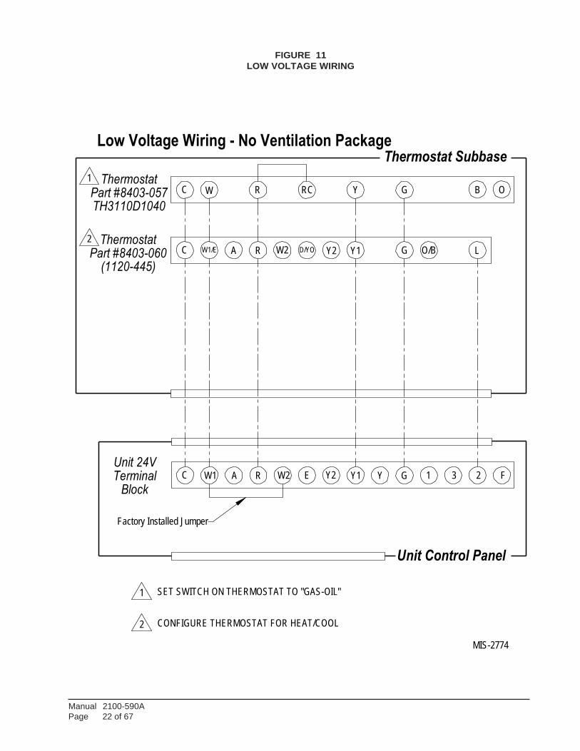
16. WIRING – LOW VOLTAGE WIRINGLow Voltage ConnectionThese units use a 24-volt AC low voltage circuit.The “R” terminal is the hot terminal and the “C”terminal is grounded.“G” terminal is the fan input.“Y1” terminal is the compressor input.“R” terminal is 24 VAC hot.“C” terminal is 24 VAC grounded.“A” terminal is the ventilation input. This terminalenergizes any factory or field installed vent option.“W1” terminal is the heat input.
230/208 VOLT UNITSAll models are equipped with dual primary voltagetransformers. All equipment leaves the factory wiredon 240V tap. For 208V operation, reconnect from240V to 208V tap. The acceptable operating voltagerange for the 240V and 208V taps are:
460 VOLT UNITSAll models are equipped with single primary voltagetransformers and no rewiring is required.
TABLE 3THERMOSTAT WIRE SIZE
remrofsnarT
AV ALF eguaGeriW
mumixaM
ecnatsiD
teeFnI
55 3.2 eguag02
eguag81
eguag61
eguag41
eguag21
54
06
001
061
052
FIGURE 10INSTALLATION OF FLEXIBLE CONDUIT
TABLE 4WALL THERMOSTAT
tatsomrehT serutaeFetanimoderP
750-3048
0401D0113HT
loocegats1,taehegats1
otua-no:naFlooc-ffo-taeh:metsyS
elbammargorP-noNcinortcelE
850-3048
1511D0225HT
taehegats2,loocegats2
elbammargorP-noNcinortcelE
lanoitnevnoCroPH
revoegnahclaunaMrootuA
060-3048
544-0211
taehegats3;loocegats3
cinortcelEelbammargorP-noN/elbammargorP
lanoitnevnoCroPH
revoegnahclaunaMrootuA
Direct Digital Controls (DDC)For total and proper control using DDC, a total of 5controlled outputs are required (4 if no ventilation isinstalled).
LOW VOLTAGE CONNECTIONS FOR DDC CONTROLFan Only Energize GCooling Mode Energize G, Y1Heating Mode Energize W1Ventilation Energize G, A
Manual 2100-590APage 22 of 67
R
Y2
Y
L
Y1
RC
D/YO
3 2
W
R
A
Factory Installed Jumper
Terminal
Y1
B
Unit 24VC
MIS-2774
Low Voltage Wiring - No Ventilation Package
1GY
Unit Control Panel
G
Block
W1/E G
W1
1
C
A W2 E Y2
O
F
C O/BR W2
Thermostat Subbase
2
1
2
SET SWITCH ON THERMOSTAT TO "GAS-OIL"
CONFIGURE THERMOSTAT FOR HEAT/COOL
ThermostatPart #8403-060
(1120-445)
ThermostatPart #8403-057TH3110D1040
FIGURE 11LOW VOLTAGE WIRING
Manual 2100-590APage 23 of 67
Part #8403-060L
1
COMMERCIAL ROOM VENTILATOR-SPRING,
Terminal W1
MIS-2775 A
RC W RC Y G
4
W2A
Block
Unit Control Panel
4
BLU
E
Y1D/YO
BLA
CK
/WH
ITE
Y2
Thermostat
SET SWITCH ON THERMOSTAT TO "GAS-OIL"
R Y1
1
WIRING PLUG
MOTORIZED FRESH AIR DAMPER,
COMMERCIAL ROOM VENTILATOR-POWERLow Voltage Wiring -
(TH311DD1040)
(MUST BE CONFIGURED
23G
HAVE OCCUPANCY OUTPUT.
Jumper
Thermostat
BR
OW
N/W
HIT
E
(1120-445)
W2
FOR HEAT/COOL)
B O
3
VENT PACKAGE
MUST INSTALL JUMPER FOR 8403-057 OR OTHER THERMOSTAT THAT DOES NOT
CONFIGURE THERMOSTAT FOR HEAT/COOL
O/BG2
A
INSTALL IF YOU REQUIRE VENTILATION ANYTIME BLOWER IS ON.
Y
Y2
C
2
E 1
W1/E
Unit 24VF
C
Thermostat Subbase
RE
D/W
HIT
E
Factory Installed
R
Part #8403-057
OR
AN
GE
3
5
5
CONNECT ORANGE WIRE TO "G" TERMINAL IF OCCUPENCY-BASED THERMOSTATOR CO2 CONTROLLER FOR DEMAND VENTILATION CONTROL IS APPLIED.
FIGURE 12LOW VOLTAGE WIRING

Manual 2100-590APage 24 of 67
C
RCW2
Terminal
W1/E
Unit Control Panel
Y
Low Voltage Wiring - EIFM ECONOMIZER
1
Y G
LY1
Unit 24V
PLUG
Y2
R
Thermostat Subbase
Factory Installed Jumper
W2 O/BG
RED
WIRES
BlockRC W1 A W2 E Y2 Y1
FROM
C
23
R
PURPLE
A
W
G
THERMISTOR
D/YO
ORANGE
Y2
WGSEIFM-5
RED
1
BLACK BLUE
PINKYELLOW
1 CONFIGURE THERMOSTAT FOR HEAT/COOL
1 ThermostatPart #8403-058(TH5220D1151)
ThermostatPart #8403-060
(1120-445)
F
MIS-2777
FIGURE 13LOW VOLTAGE WIRING
Manual 2100-590APage 25 of 67
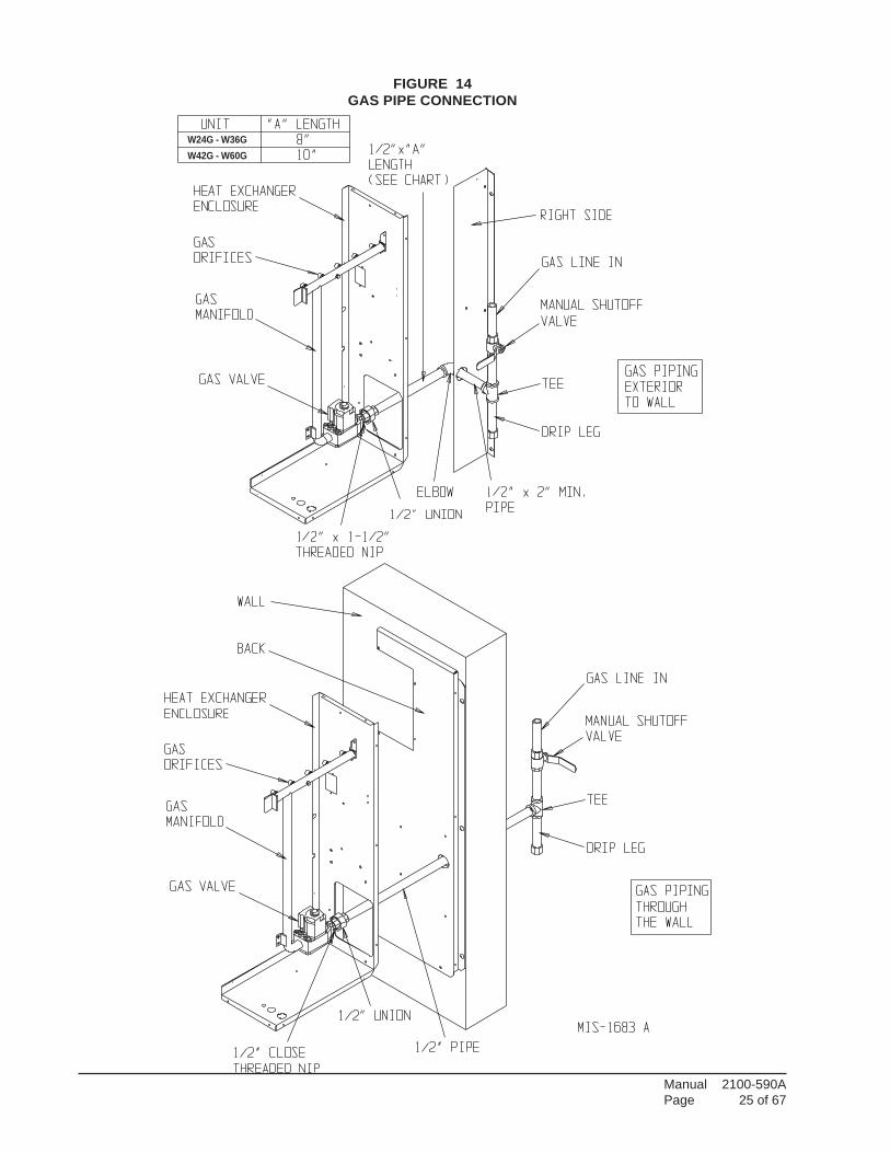
FIGURE 14GAS PIPE CONNECTION
W24G - W36GW42G - W60G
Manual 2100-590APage 26 of 67
18. GAS SUPPLY AND PIPING
GENERAL RECOMMENDATIONS1. Be sure the gas line complies with the local codes
and ordinances, or in their absence with the NationalFuel Gas Code, ANSI Z223.1, or Natural GasInstallation Code, CAN/CGA B149.1, or PropaneInstallation Code B149.2, latest edition.
2. A sediment trap or drip leg must be installed in thesupply line to the furnace.
3. A ground joint union shall be installed in the gas lineadjacent to and upstream from the gas valve anddownstream from the manual shut off valve.
4. An 1/8" NPT plugged tapping accessible for testgauge connection shall be installed immediatelyupstream of the gas supply connection to the furnacefor the purpose of determining the supply gaspressure. This can be omitted if local codes permituse of plugged tapping in gas valve inlet.
5. Install listed manual shut off valve in the supply gasline external to and immediately upstream of thefurnace. See Figure 14.
6. Use steel or wrought iron pipe and fittings.
7. DO NOT thread pipe too far. Valve distortion ormalfunction may result from excess pipe within thecontrol. Use pipe joint compound resistant to theaction of liquefied petroleum gases on male threadsonly. DO NOT use Teflon tape. See Table 5 andFigure 15.
TABLE 5LENGTH OF STANDARDPIPE THREADS (INCHES)
eziSepiP
htgneLevitceffE
daerhTfo
htgneLllarevO
daerhTfo
8/3 2/1 61/9
4/3 61/9--2/1 61/31
1 61/9 1
fohtgneL
teeF-epiP
eziSepiPtupnIruoHrepUTB-yticapaCepiP
"2/1 "4/3 "1 "4/1-1
01 000,231 000,872 000,025 000,050,1
02 000,29 000,091 000,053 000,037
03 000,37 000,251 000,582 000,095
04 000,36 000,031 000,542 000,005
05 000,65 000,511 000,512 000,044
06 000,05 000,501 000,591 000,004
07 000,64 000,69 000,081 000,073
08 000,34 000,09 000,071 000,053
001 000,83 000,97 000,051 000,503
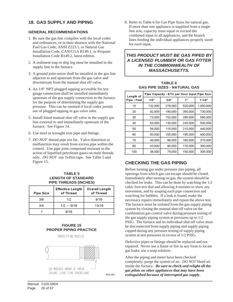
TABLE 6GAS PIPE SIZES - NATURAL GAS
CHECKING THE GAS PIPINGBefore turning gas under pressure into piping, allopenings from which gas can escape should be closed.Immediately after turning on gas, the system should bechecked for leaks. This can be done by watching the 1/2cubic foot test dial and allowing 4 minutes to show anymovement, and by soaping each pipe connection andwatching for bubbles. If a leak is found, make thenecessary repairs immediately and repeat the above test.The furnace must be isolated from the gas supply pipingsystem by closing the manual shut off valve on thecombination gas control valve during pressure testing ofthe gas supply piping system at pressures up to 1/2PSIG. The furnace and its individual shut off valve mustbe disconnected from supply piping and supply pipingcapped during any pressure testing of supply pipingsystem at test pressures in excess of 1/2 PSIG.
Defective pipes or fittings should be replaced and notrepaired. Never use a flame or fire in any form to locategas leaks; use a soap solution.
After the piping and meter have been checkedcompletely, purge the system of air. DO NOT bleed airinside the furnace. Be sure to check and relight all thegas pilots on other appliances that may have beenextinguished because of interrupted gas supply.
FIGURE 15PROPER PIPING PRACTICE
8. Refer to Table 6 for Gas Pipe Sizes for natural gas.If more than one appliance is supplied from a singleline size, capacity must equal or exceed thecombined input to all appliances, and the branchlines feeding the individual appliances properly sizedfor each input.
MIS-897
THIS PRODUCT MUST BE GAS PIPED BYA LICENSED PLUMBER OR GAS FITTER
IN THE COMMONWEALTH OFMASSACHUSETTS.
Manual 2100-590APage 27 of 67
19. MANIFOLD PRESSUREADJUSTMENTYou will need a 0 to 15 inch water manometer with 0.1inch resolution and a 1/8" NPT manual shut off valve tomeasure actual manifold pressure.
Depending on your local gas heating value andelevation, you may need to adjust manifold pressure orchange orifices to get proper gas input rate. Checkwith your local gas supplier to determine heating value(BTU/cu. ft.) of natural gas in your area.
NOTE: If furnace is being installed at an altitude ofmore than 6,000 feet above sea level, youmust derate the furnace. See Section 21“Standard Orifice Sizing and High AltitudeDerate”.
20. CHECKING GAS INPUT RATEIt is the installer's responsibility to see that the BTUinput rate of the furnace is properly adjusted. Under-firing could cause inadequate heat, excessivecondensation or ignition problems. Overfiring couldcause sooting, flame impingement or overheating ofheat exchanger.
1. Turn off gas at equipment shut off valve in gassupply line just ahead of furnace.
2. Remove plug from outlet pressure tap in gas controlor gas manifold.
3. Install 1/8" NPT manual shut off valve in holevacated by plug. Make sure shut off valve is in offposition.
4. Attach manometer to 1/8" NPT manual shut offvalve just installed.
PROPANE (LP) GAS CONVERSIONThis unit may be converted in the field foruse with Propane (LP) gas. Propane gasconversion kit number WGCK-1 is designedfor conversions of units installed from0 – 6,000 feet elevations. Propane gasconversion kit number WGCK-2 is designedfor conversions of units installed from 6,001– 10,000 feet elevations. These kits maybe purchased from your local distributor.
5. Slowly open equipment shut off valve in gas supplyline just ahead of furnace. Start furnace following“Operating Instructions” on front door.
6. Slowly open 1/8" NPT manual shut off valve leadingto manometer.
7. Read manifold pressure on manometer.
8. Adjust manifold pressure by turning gas controlregulator adjusting screw clockwise to increasepressure or turning counterclockwise to decreasepressure. Manifold pressure must be withinallowable range as follows:• Natural gas manifold pressure must be between
3.2 and 3.8 inches W.C. Rated pressure is 3.5inches.
• Propane gas (LP) manifold pressure must bebetween 9.7 and 10.3 inches W.C. Ratedpressure is 10 inches.
NOTE: For natural gas, if gas flow rate can't beproperly set within these pressure rangesthen you must change main burner orifices toobtain proper gas flow rate.
9. Shut off furnace. Turn off gas at equipment shut offvalve in gas supply line just ahead of furnace. Installoutlet pressure tap plug in gas control. Turn on gas.
10. Check regulator adjustment cover screw and gascontrol plug for gas leaks. Use a commercial soapsolution made for leak detection.
WARNINGFailure to adjust furnace to the proper firingrate could cause heat exchanger failure.
WARNINGWhen converting from propane (LP) gas tonatural gas, the gas orifice spuds and gasvalve spring must be replaced and the gasvalve regulator pressure must be adjustedcorrectly. Failure to do so can result in fire,injury or death. Refer to Tables 8 and 8A forproper orifice sizing.
Natural gas spring kit, Part number 5603-007,can be purchased through your localdistributor.
WARNINGCorrect manifold pressure is necessary forproper ignition and burner operation. Failureto accurately adjust pressure could causeheat exchanger failure.
Manual 2100-590APage 28 of 67
NATURAL GAS INPUT RATENatural gas heating value (BTU/cu. ft.) can varysignificantly. Before starting natural gas input check,obtain gas heating value at your location from localsupplier. You will need a stopwatch to measure actualgas input.
1. Gas supply pressure must be between 5 and 7 inchesW.C. for natural gas.
2. Turn off all other gas appliances. You may leavepilots on.
3. Start furnace following “Operating Instructions” onfront door.
4. Let furnace warm up for 6 minutes.
5. Locate gas meter. Determine which dial has theleast cubic feet of gas and how many cubic feet perrevolution it represents. This is usually one-half, oneor two cubic feet per revolution.
6. With stopwatch, measure time it takes to consumetwo cubic feet of gas.
• If dial is one-half cubic foot per revolution,measure time for four revolutions.
• If dial is one cubic foot per revolution, measuretime for two revolutions.
• If dial is two cubic feet per revolution, measuretime for one revolution.
7. Divide this time by two. This gives average time forone cubic foot of gas to flow through meter.Example: If it took 58 seconds for two cubic feet toflow, it would take 29 seconds for one cubic foot toflow.
8. Calculate gas input using this formula:
Gas Heating Value (BTU/cu. ft.) x 3,600 sec/hr
Gas input = = BTU/hour Time (Seconds for one
cubic foot of gas)
Example:Assume it took 29 seconds for one cubic foot of gasto flow and heating value of 1,000 BTU/cu. ft.
1,000 x 3,600 Gas input = = 124,138 BTU 29
If you left no other pilots on, this is the furnace gasinput.
PROPANE (LP) GAS INPUT RATE
1. Make sure you have proper main burner orifices.
2. Gas supply pressure must be between 11 and 13inches W.C. for propane (LP) gas.
3. Start furnace following “Operating Instructions” onfront door.
4. Let furnace warm up for 6 minutes.
5. Adjust manifold pressure to 10.0 W.C. ± 0.3 inchesW.C. See Section 19, “Manifold PressureAdjustment”.
WARNINGPropane (LP) gas installations do not havegas meters to double check input rate.Measure manifold pressure adjustment withan accurate manometer. Failure to accuratelyadjust pressure could cause heat exchangerfailure, asphyxiation, fire or explosion,resulting in damage, injury or death.
WARNINGDo not set Propane (LP) manifold pressure at11.0 inches W.C. It could cause heatexchanger failure.
9. If you left water heater, dryer or range pilots on,allow for them in calculating correct furnace gasinput. A quick way is to allow 1,000 BTU per hourfor a water heater, 500 BTU per hour for dryer and500 BTU per hour for each range burner pilot.
Example:
If you left gas water heater, dryer, two range burnerpilots and one oven pilot on, allow:
Water heater pilot 1,000 BTU per hourDryer pilot 500 BTU per hour2 range burner pilots 1,000 BTU per hour1 range oven pilot 500 BTU per hour
3,000 BTU per hour
Subtracting 3,000 BTU per hour from 124,138 BTUper hour measured above equals 121,138 BTU perhour. This would be the correct furnace gas inputafter allowing for pilots left on.
10. Manifold pressure may be adjusted within the rangeof 3.2 inches W.C. to 3.8 inches W.C. to get ratedinput ± 2 percent. See Section 19, “ManifoldPressure Adjustment”. If you cannot get rated inputwith manifold pressure within the allowable range,you must change orifices.
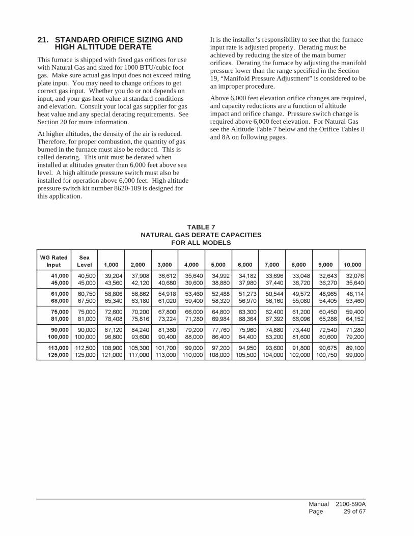
Manual 2100-590APage 29 of 67
21. STANDARD ORIFICE SIZING AND HIGH ALTITUDE DERATEThis furnace is shipped with fixed gas orifices for usewith Natural Gas and sized for 1000 BTU/cubic footgas. Make sure actual gas input does not exceed ratingplate input. You may need to change orifices to getcorrect gas input. Whether you do or not depends oninput, and your gas heat value at standard conditionsand elevation. Consult your local gas supplier for gasheat value and any special derating requirements. SeeSection 20 for more information.
At higher altitudes, the density of the air is reduced.Therefore, for proper combustion, the quantity of gasburned in the furnace must also be reduced. This iscalled derating. This unit must be derated wheninstalled at altitudes greater than 6,000 feet above sealevel. A high altitude pressure switch must also beinstalled for operation above 6,000 feet. High altitudepressure switch kit number 8620-189 is designed forthis application.
TABLE 7NATURAL GAS DERATE CAPACITIES
FOR ALL MODELS
detaRGW
tupnI
aeS
leveL 000,1 000,2 000,3 000,4 000,5 000,6 000,7 000,8 000,9 000,01
000,14
000,54
005,04
000,54
402,93
065,34
809,73
021,24
216,63
086,04
046,53
006,93
299,43
088,83
281,43
089,73
696,33
044,73
840,33
027,63
346,23
072,63
670,23
046,53
000,16
000,86
057,06
005,76
608,85
043,56
268,65
081,36
819,45
020,16
064,35
004,95
884,25
023,85
372,15
079,65
445,05
061,65
275,94
080,55
569,84
504,45
411,84
064,35
000,57
000,18
000,57
000,18
006,27
804,87
002,07
618,57
008,76
422,37
000,66
082,17
008,46
489,96
003,36
463,86
004,26
293,76
002,16
690,66
054,06
682,56
004,95
251,46
000,09
000,001
000,09
000,001
021,78
008,69
042,48
006,39
063,18
004,09
002,97
000,88
067,77
004,68
069,57
004,48
088,47
002,38
044,37
006,18
045,27
006,08
082,17
002,97
000,311
000,521
005,211
000,521
009,801
000,121
003,501
000,711
007,101
000,311
000,99
000,011
002,79
000,801
059,49
005,501
006,39
000,401
008,19
000,201
576,09
057,001
001,98
000,99
It is the installer’s responsibility to see that the furnaceinput rate is adjusted properly. Derating must beachieved by reducing the size of the main burnerorifices. Derating the furnace by adjusting the manifoldpressure lower than the range specified in the Section19, “Manifold Pressure Adjustment” is considered to bean improper procedure.
Above 6,000 feet elevation orifice changes are required,and capacity reductions are a function of altitudeimpact and orifice change. Pressure switch change isrequired above 6,000 feet elevation. For Natural Gassee the Altitude Table 7 below and the Orifice Tables 8and 8A on following pages.
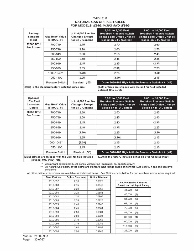
Manual 2100-590APage 30 of 67
All other orifice sizes shown are available as individual items. See Orifice charts below for part numbers and number required.
TABLE 8NATURAL GAS ORIFICE TABLES
FOR MODELS W24G, W30G AND W36G
yrotcaF
dradnatS
tupnI
eulaV*taeHsaG
.tF.uC/UTB
oNteeF000,6otpU
tpecxEsegnahC
tnetnoCUTBrof
teeF000,8ot100,6
hctiwSerusserPseriuqeR
egnahCecifirOdnaegnahC
tnetnoCUTBnodesaB t
teeF000,01ot100,8
hctiwSerusserPseriuqeR
egnahCecifirOdnaegnahC
tnetnoCUTBnodesaB t
UTB00522
renruBreP947-007 57.2 07.2 06.2
997-057 07.2 06.2 05.2
948-008 06.2 05.2 54.2
998-058 05.2 54.2 53.2
949-009 54.2 53.2 )03.2(
999-059 53.2 )03.2( 52.2
**9401-0001 )03.2( 52.2 ]02.2[
0011-0501 52.2 ]02.2[ 51.2
hctiwSerusserP )55.(dradnatS )24.(tiKhctiwSerusserPedutitlAhgiH981-0268redrO
ezisecifirodellatsniyrotcafdradnatsehtsi)03.2( dellatsnidleifroftinuehthtiwdeppihserasecifiro]02.2[
etared%01lanoitpo
lanoitpO
dleiF%01
detrevnoC
etareD
eulaV*taeHsaG
.tF.uC/UTB
oNteeF000,6otpU
tpecxEsegnahC
tnetnoCUTBrof
teeF000,8ot100,6
hctiwSerusserPseriuqeR
egnahCecifirOdnaegnahC
tnetnoCUTBnodesaB
teeF000,01ot100,8
hctiwSerusserPseriuqeR
egnahCecifirOdnaegnahC
tnetnoCUTBnodesaB
UTB05202
renruBreP947-007 06.2 05.2 54.2
997-057 05.2 54.2 04.2
948-008 54.2 04.2 )03.2(
998-058 04.2 )03.2( 52.2
949-009 )03.2( 52.2 ]02.2[
999-059 52.2 ]02.2[ 51.2
**9401-0001 ]02.2[ 51.2 01.2
0011-0501 51.2 51.2 01.2
hctiwSerusserP )55.(dradnatS )24.(tiKhctiwSerusserPedutitlAhgiH981-0268redrO
dellatsnidleifroftinuehthtiwdeppihserasecifiro]02.2[
.etartupni%01lanoitpo
tupnidetarllufrofezisecifirodellatsniyrotcafehtsi)03.2(
***
.ytivargcificeps06.,detarutas,F06,yrucreMsehcni00.03:snoitidnocdradnatstA
levelaesdnasagtfuc/UTB5201lanimonnodesabsgnitartupnidradnatsdnagnizisecifiroyrotcafsaGlarutaNllA
snoitidnoc
.oNtraPdraB )mm(eziSecifirO retemaiDecifirO
290-0109 01.2 6280.0
880-0109 51.2 6480.0
780-0109 02.2 6680.0
680-0109 52.2 5880.0
280-0109 03.2 5090.0
580-0109 53.2 5290.0
970-0109 04.2 5490.0
480-0109 54.2 4690.0
390-0109 05.2 4890.0
490-0109 06.2 4201.0
590-0109 07.2 3601.0
690-0109 57.2 2801.0
790-0109 08.2 2011.0
890-0109 09.2 2411.0
deriuqeRsecifirOfo.oN
gnitaRtupnItinUnodesaB
000,14 )2(
000,54 )2(
000,16 )3(
000,86 )3(
000,57 )3(
000,18 )4(
000,09 )4(
000,001 )4(
000,311 )5(
000,521 )5(
Manual 2100-590APage 31 of 67
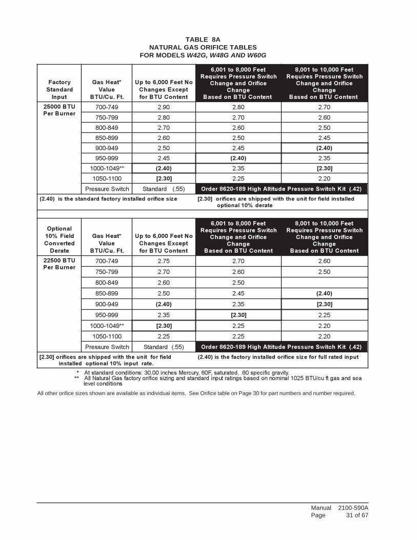
All other orifice sizes shown are available as individual items. See Orifice table on Page 30 for part numbers and number required.
TABLE 8ANATURAL GAS ORIFICE TABLES
FOR MODELS W42G, W48G AND W60G
yrotcaF
dradnatS
tupnI
*taeHsaG
eulaV
.tF.uC/UTB
oNteeF000,6otpU
tpecxEsegnahC
tnetnoCUTBrof
teeF000,8ot100,6
hctiwSerusserPseriuqeR
ecifirOdnaegnahC
egnahC
tnetnoCUTBnodesaB t
teeF000,01ot100,8
hctiwSerusserPseriuqeR
ecifirOdnaegnahC
egnahC
tnetnoCUTBnodesaB t
UTB00052
renruBreP947-007 09.2 08.2 07.2
997-057 08.2 07.2 06.2
948-008 07.2 06.2 05.2
998-058 06.2 05.2 54.2
949-009 05.2 54.2 )04.2(
999-059 54.2 )04.2( 53.2
**9401-0001 )04.2( 53.2 ]03.2[
0011-0501 ]03.2[ 52.2 02.2
hctiwSerusserP )55.(dradnatS )24.(tiKhctiwSerusserPedutitlAhgiH981-0268redrO
ezisecifirodellatsniyrotcafdradnatsehtsi)04.2( dellatsnidleifroftinuehthtiwdeppihserasecifiro]03.2[
etared%01lanoitpo
lanoitpO
dleiF%01
detrevnoC
etareD
*taeHsaG
eulaV
.tF.uC/UTB
oNteeF000,6otpU
tpecxEsegnahC
tnetnoCUTBrof
teeF000,8ot100,6
hctiwSerusserPseriuqeR
ecifirOdnaegnahC
egnahC
tnetnoCUTBnodesaB
teeF000,01ot100,8
hctiwSerusserPseriuqeR
ecifirOdnaegnahC
egnahC
tnetnoCUTBnodesaB
UTB00522
renruBreP947-007 57.2 07.2 06.2
997-057 07.2 06.2 05.2
948-008 06.2 05.2
998-058 05.2 54.2 )04.2(
949-009 )04.2( 53.2 ]03.2[
999-059 53.2 ]03.2[ 52.2
**9401-0001 ]03.2[ 52.2 02.2
0011-0501 52.2 52.2 02.2
hctiwSerusserP )55.(dradnatS )24.(tiKhctiwSerusserPedutitlAhgiH981-0268redrO
dleifroftinuehthtiwdeppihserasecifiro]03.2[
.etartupni%01lanoitpodellatsni
tupnidetarllufrofezisecifirodellatsniyrotcafehtsi)04.2(
***
.ytivargcificeps06.,detarutas,F06,yrucreMsehcni00.03:snoitidnocdradnatstAaesdnasagtfuc/UTB5201lanimonnodesabsgnitartupnidradnatsdnagnizisecifiroyrotcafsaGlarutaNllA
snoitidnoclevel
Manual 2100-590APage 32 of 67
23. MEASURING AIR TEMPERATURERISE
Air temperature rise (supply air temperature minusreturn air temperature) must be within allowable airtemperature rise range specified on furnace rating plate.
You will need 2 thermometers with 1 degree resolutioncapable of reading up to 200 degrees F. Checkthermometers to make sure they agree, or compensateaccordingly.
Follow this procedure:
1. Open supply air registers and return air grilles.Make sure the registers and grilles are free ofobstruction from rugs, carpets, drapes or furniture.
22. CONVERSION OF GAS INPUT BTUHFROM HIGH TO LOW RATINGAll the derated WG series units are produced withmaximum BTUH input orifices installed. To fieldconvert input, a change to main burner orifices isrequired.
NOTE: No change to air orifices is necessary. A setof low input orifices is shipped with everyunit. They will be found packaged in a bagbehind the burner door. Refer to the unitrating plate to confirm the proper orifice size.Proper installation of the orifices is detailedas follows:
A. Shut off electrical supply to the unit.
B. Shut off gas supply to the unit.
C. Remove burner access panel.
D. Disconnect gas valve from gas supply piping.
E. Disconnect the two wires from the gas valve.
F. Remove the manifold assembly so that orifices arenow accessible and remove orifices.
G. Apply a modest amount of pipe compound to thenew orifices and screw them into the manifold.
H. To assemble burner reverse steps A through G.
2. Set balancing dampers in supply duct system.
3. Check duct work for obstructions or leaks.
4. Make sure filters are clean and in place.
5. Place one thermometer in supply air plenumapproximately 2 feet from furnace. Locatethermometer tip in center of plenum to insure propertemperature measurement.
6. Place second thermometer in return air ductapproximately 2 feet from furnace. Locatethermometer tip in center of duct to insure propertemperature measurement.
7. Set room thermostat on highest temperature setting.Operate furnace 10 minutes. Record supply air andreturn air temperatures.
8. Calculate air temperature rise by subtracting returnair temperature from supply air temperature.
• If air temperature rise is above the temperaturerise range on rating plate, furnace is overfiredor has insufficient airflow. Check gas inputfollowing the instructions in Section, “CheckingGas Input Rate”. If air temperature rise is stillabove temperature rise rangespecified, moreheating airflow is needed. Check duct work andgrilles to make sure all are properly sized.
• If air temperature rise is below the temperaturerise range on rating plate, furnace is underfiredor has too much airflow. Check gas inputfollowing the instructions in Section, “CheckingGas Input Rate”. If air temperature rise is stillbelow temperature rise range specified, lessheating airflow is needed. Adjust dampers orgrilles as needed.
• After making adjustments, you must check airtemperature rise to verify that resulting airtemperature rise is within allowable range. Ifair temperature rise is still outside thetemperature rise range specified on ratingplate, check duct system design with aqualified heating engineer. It may benecessary to re-size the duct work. Recheckair temperature rise after revising duct systems.
9. Set room thermostat to desired setting.
10. Remove thermometers and seal duct work holes.
NOTE: Failure to seal holes could result in reducedsystem performance.
WARNINGFailure to follow these instructions couldcreate a hazard resulting in property damage,bodily injury, or death.
Manual 2100-590APage 33 of 67
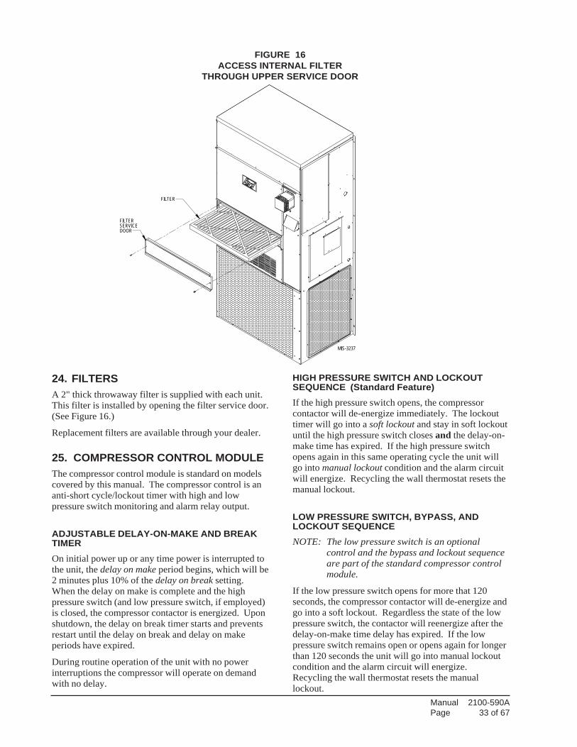
24. FILTERSA 2" thick throwaway filter is supplied with each unit.This filter is installed by opening the filter service door.(See Figure 16.)
Replacement filters are available through your dealer.
25. COMPRESSOR CONTROL MODULEThe compressor control module is standard on modelscovered by this manual. The compressor control is ananti-short cycle/lockout timer with high and lowpressure switch monitoring and alarm relay output.
ADJUSTABLE DELAY-ON-MAKE AND BREAKTIMEROn initial power up or any time power is interrupted tothe unit, the delay on make period begins, which will be2 minutes plus 10% of the delay on break setting.When the delay on make is complete and the highpressure switch (and low pressure switch, if employed)is closed, the compressor contactor is energized. Uponshutdown, the delay on break timer starts and preventsrestart until the delay on break and delay on makeperiods have expired.
During routine operation of the unit with no powerinterruptions the compressor will operate on demandwith no delay.
HIGH PRESSURE SWITCH AND LOCKOUTSEQUENCE (Standard Feature)If the high pressure switch opens, the compressorcontactor will de-energize immediately. The lockouttimer will go into a soft lockout and stay in soft lockoutuntil the high pressure switch closes and the delay-on-make time has expired. If the high pressure switchopens again in this same operating cycle the unit willgo into manual lockout condition and the alarm circuitwill energize. Recycling the wall thermostat resets themanual lockout.
LOW PRESSURE SWITCH, BYPASS, ANDLOCKOUT SEQUENCENOTE: The low pressure switch is an optional
control and the bypass and lockout sequenceare part of the standard compressor controlmodule.
If the low pressure switch opens for more that 120seconds, the compressor contactor will de-energize andgo into a soft lockout. Regardless the state of the lowpressure switch, the contactor will reenergize after thedelay-on-make time delay has expired. If the lowpressure switch remains open or opens again for longerthan 120 seconds the unit will go into manual lockoutcondition and the alarm circuit will energize.Recycling the wall thermostat resets the manuallockout.
FIGURE 16ACCESS INTERNAL FILTER
THROUGH UPPER SERVICE DOOR
MIS-3237
FILTER
FILTER SERVICEDOOR
Manual 2100-590APage 34 of 67
ALARM OUTPUTAlarm terminal is output connection for applicationswhere alarm signal is desired. This terminal is poweredwhenever compressor is locked out due to HPC or LPCsequences as described.
NOTE: Both high and low pressure switch controlsare inherently automatic reset devices. Thehigh pressure switch and low pressure switchcut out and cut in settings are fixed byspecific air conditioner or heat pump unitmodel. The lockout features, both soft andmanual, are a function of the CompressorControl Module.
ADJUSTMENTS
ADJUSTABLE DELAY-ON-MAKE ANDDELAY-ON-BREAK TIMERThe potentiometer is used to select Delay-on-Breaktime from 30 seconds to 5 minutes. Delay-on-Make(DOM) timing on power-up and after powerinterruptions is equal to 2 minutes plus 10% of Delay-on-Break (DOB) setting:
0.5 minute (30 seconds) DOB = 123 second DOM1.0 minute (60 seconds) DOB = 126 second DOM2.0 minute (120 seconds) DOB = 132 second DOM3.0 minute (160 seconds) DOB = 138 second DOM4.0 minute (240 seconds) DOB = 144 second DOM5.0 minute (300 seconds) DOB = 150 second DOM
PHASE MONITORAll units with three phase scroll compressors areequipped with a three phase line monitor to preventcompressor damage due to phase reversal.
The phase monitor in this unit is equipped with twoLEDs. If the “Y” signal is present at the phase monitorand phases are correct, the green LED will light.
If phases are reversed, the red fault LED will be lit andcompressor operation is inhibited.
If a fault condition occurs, reverse two of the supplyleads to the unit. Do not reverse any of the unit factorywires as damage may occur.
Manual 2100-590APage 35 of 67
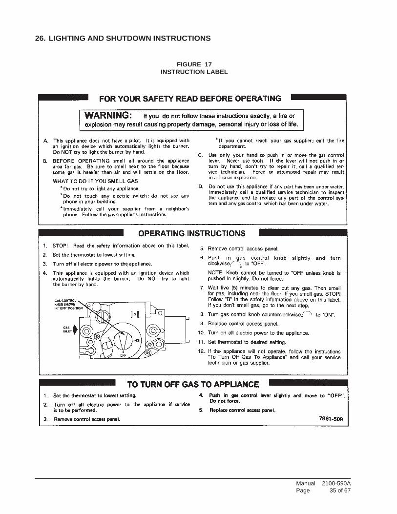
26. LIGHTING AND SHUTDOWN INSTRUCTIONS
FIGURE 17INSTRUCTION LABEL
Manual 2100-590APage 36 of 67
27. SERVICE AGENCY PROCEDURES
MAIN BURNER
Observe the main burners in operation. The flameshould be mostly “blue” with possibly a little orange(not yellow) at the tips of the flame. The flames shouldbe in the center of the heat exchanger tubes and notimpinging on the heat exchanger surfaces themselves.
Observe the fire until the blower starts (there is anormal delay period until the heat exchanger warmsup). There should be no change in the size or shape ofthe flame. If there is any wavering or blowing of theflame on blower start-up, it is an indication of apossible leak in the heat exchanger.
28. MAINTAINING UNIT IN GOODWORKING ORDER
The unit should be inspected annually by a qualifiedservice agency.
BURNERS / HEAT EXCHANGER / FLUE GASPASSAGE WAYS
The burners, heat exchanger and interior flue gaspassages may be inspected using a light on small mirroror an extension handle. Remove the screws securingthe inducer and collector box. Now inspect the uppertubes of the heat exchanger.
Check the exterior of the heat exchanger and theinterior flue gas passages for any evidence ofdeterioration due to corrosion, cracking or other causes.If signs of sooting exist, remove the burners and cleanthe heat exchanger, as required.
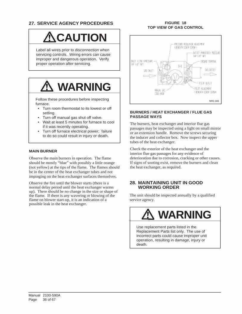
MIS-165
FIGURE 18TOP VIEW OF GAS CONTROL
CAUTIONLabel all wires prior to disconnection whenservicing controls. Wiring errors can causeimproper and dangerous operation. Verifyproper operation after servicing.
WARNINGFollow these procedures before inspectingfurnace. • Turn room thermostat to its lowest or off
setting. • Turn off manual gas shut off valve. • Wait at least 5 minutes for furnace to cool
if it was recently operating. • Turn off furnace electrical power; failure
to do so could result in injury or death.
WARNINGUse replacement parts listed in theReplacement Parts list only. The use ofincorrect parts could cause improper unitoperation, resulting in damage, injury ordeath.
Manual 2100-590APage 37 of 67
ROUTINE MAINTENANCE
1. Air Filters – Check the condition at least monthlywhen the unit is in use, and replace as necessary.
2. Lubrication Requirements – The indoor circulatingair blower motor and outdoor circulating air fanmotor are permanently lubricated and requires no re-oiling. The combustion air blower motor requires nore-oiling.
ROUTINE INSPECTION
1. Inspect the physical support of the unit annually tomake sure it is securely fastened to the building.Also look for any obvious signs of deterioration.
2. Inspect the main burners at the beginning of eachheating season and clean as necessary.
3. Inspect the vent terminal and combustion air intakehood for any obvious deterioration, to make sure it isfree and clear of any obstructions.
29. REPLACEMENT PARTS
ANNUAL MAINTENANCE
Routine inspection and maintenance procedures are theresponsibility of the user and are outlined below.
1. Before inspecting unit:
a. Turn room thermostat to lowest or off setting.
b. Turn off equipment gas shut off valve.
c. Wait for unit to cool if it was recentlyoperating.
d. Turn off electrical power to unit.
2. Inspect the following:
a. Vent terminal and combustion air intaketerminal. Make sure both are free fromobstructions.
b. Vertical Vent Applications – Inspect ventingsystem. Make sure system has no holes, isphysically sound and free from obstructions.
c. Make sure the supply and return air flangesleeves or duct work are securely fastened tounit and physically sound.
d. Supply and return grilles must be open andfree from obstructions.
e. Inspect to make sure the unit is securelyfastened to the wall. Seal any possible leaksbetween unit and wall with appropriateexterior sealing material.
f. Inspect burners, heat exchanger, induceddraft blower, and induced draft blowercollector box. There must be no obvioussigns of deterioration.
g. Inspect all electrical connections and wiring.
h. Check all gas piping for leaks with soapsolution used to detect leaks.
i. Inspect, clean, and repair as needed the entireblower assembly, air filters, draft inducer,cooling coils, and vent options (if installed).
Replacement parts for the gas/electric units areavailable through local distributors.
A replacement parts list manual is supplied with eachunit. When ordering parts or making inquirespertaining to any of the units covered by theseinstructions, it is very important to always supply thecomplete model number and serial number of the unit.This is necessary to assure that the correct parts (or anapproved alternate part) are issued to the serviceagency.
WARNINGDisconnect electrical power before servicingunit. Failure to do so could result in electricalshock or death.
WARNINGTurn off electrical power supply to preventinjury from moving parts or electric shock.
WARNINGUse replacement parts listed in ReplacementParts list. Failure to do so could causeimproper furnace operation, resulting inproperty damage, personal injury, or death.

Manual 2100-590APage 38 of 67
30. SEQUENCE OF OPERATION –HEATING
On a call for heat from the thermostat, the induced draftblower is energized. Once sufficient draft isestablished, the pressure switch contacts close and theignition system is energized. The direct spark ignitorwill be energized allowing gas to flow. At the sametime the main valve is energized, a 30-second blowerdelay timer is activated.
After this delay, the heating speed blower relayenergizes. The blower will begin operating and remainin operation until the set delay time after the call forheat has been satisfied. (See Tables 10-15 for selectableblower off time delays.) This timing sequenceguarantees blower on, blower off operation.
This unit is equipped with a flame roll-out switch,which is wired in series with the control circuit. This isa manual reset switch and is used for the purpose ofpreventing possible fire hazard in the event of a systemmalfunction. If this switch has opened the controlcircuit, there could be a possible system malfunction.Some of the conditions that might cause a roll-out tooccur are blockage or sooting of primary heatexchanger, overfiring of furnace due to improper main
burner orifices or incorrect manifold pressure,insufficient combustion air, or installation deficiencieswith respect to return air duct design or sizing.
Once the problem has been resolved, reset the switch bypressing down on the reset button on top of the switch.See Figure 19 for additional information.
31. SEQUENCE OF OPERATION –COOLING
On a call for cooling from the room thermostat, the highspeed blower relay will be energized as well as thecompressor contactor. Following termination of thecooling cycle, the blower motor will continue to run forone minute.
See Figure 19 for additional information.
The unit may be equipped with a low ambient controlfor lower outdoor temperature operation in the coolingmode. If equipped with this optional control thecondenser fan will not operate immediately uponcompressor start-up, and will cycle on and off until thecondensing pressure remains above 180 PSIG. LACenergizes the fan motor at 280 PSIG, de-energizes at180 PSIG.
FIGURE 19SEQUENCE OF OPERATION
ELECTRONIC BLOWER CONTROL
NOITCA ESNOPSERMETSYS
.taehrofsllactatsomrehT
).dezigrenesilanimretW(
•
•
•
•
•
.dezigrenesirewolbrianoitsubmoC
.dehsilbatsesiwolfriA.sekamhctiwsgnivorpriA
.dezigrenesimetsysnoitingI
.sthgilrenrubniamdnasnepoevlavsaG
sinafgnitalucriceht,etelpmocsignimitnehW.snigebgnimityalednonaftaeH.deepstaehtadezigrene
.taehrofllacsdnetatsomrehT •
•
•
.sesolcevlavsagdnadezigrene-edsimetsysnoitingI
.gnimitegruptsopretfadezigrene-edsirewolbrianoitsubmoC
sinafgnitalucriceht,etelpmocsignimitnehW.snigebgnimityaledffonaftaeH.dezigrene-ed
.loocrofllacsnigebtatsomrehT
).dezigrene-erslanimretYdnaG(
•
•
.dezigrenesirotcatnocgnilooC
.gnimityalednonafloocretfadeepsloocnodezigrenesinafgnitalucriC
.nafrofllacsdnetatsomrehT
).dezigrene-edsilanimretG(
• dezigrene-edsinafgnitalucriC
.snepo)tuolloremalf(timiL •
•
.sesolcevlavsagdnadezigrene-ederametsysnoitingidnatatsomrehT
narewolbrianoitsubmoC d .dezigreneeradeepstaehnafgnitalucric
tuolloremalfro)teserotua(timiL.desolctiucric)teserlaunam(
•
•
•
.gnimitegruptsoprofdezigrenesniamerrrewolbrianoitsubmoC
.gnimitffoyaleddetcelesehtrofdezigrenesniamernafnoitalucricehT
.semusernoitarepolamroN
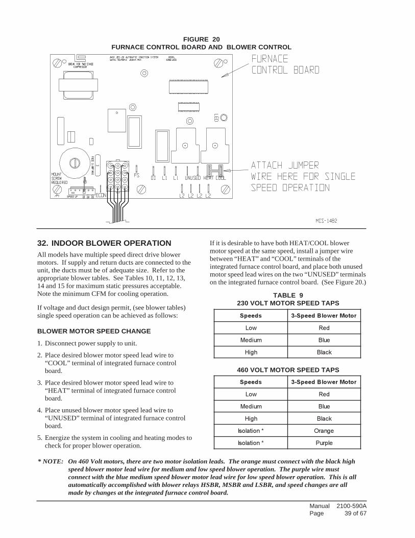
Manual 2100-590APage 39 of 67
32. INDOOR BLOWER OPERATIONAll models have multiple speed direct drive blowermotors. If supply and return ducts are connected to theunit, the ducts must be of adequate size. Refer to theappropriate blower tables. See Tables 10, 11, 12, 13,14 and 15 for maximum static pressures acceptable.Note the minimum CFM for cooling operation.
If voltage and duct design permit, (see blower tables)single speed operation can be achieved as follows:
BLOWER MOTOR SPEED CHANGE
1. Disconnect power supply to unit.
2. Place desired blower motor speed lead wire to“COOL” terminal of integrated furnace controlboard.
3. Place desired blower motor speed lead wire to“HEAT” terminal of integrated furnace controlboard.
4. Place unused blower motor speed lead wire to“UNUSED” terminal of integrated furnace controlboard.
5. Energize the system in cooling and heating modes tocheck for proper blower operation.
If it is desirable to have both HEAT/COOL blowermotor speed at the same speed, install a jumper wirebetween “HEAT” and “COOL” terminals of theintegrated furnace control board, and place both unusedmotor speed lead wires on the two “UNUSED” terminalson the integrated furnace control board. (See Figure 20.)
sdeepS rotoMrewolBdeepS-3
woL deR
muideM eulB
hgiH kcalB
sdeepS rotoMrewolBdeepS-3
woL deR
muideM eulB
hgiH kcalB
*noitalosI egnarO
*noitalosI elpruP
FIGURE 20FURNACE CONTROL BOARD AND BLOWER CONTROL
TABLE 9230 VOLT MOTOR SPEED TAPS
460 VOLT MOTOR SPEED TAPS
* NOTE: On 460 Volt motors, there are two motor isolation leads. The orange must connect with the black highspeed blower motor lead wire for medium and low speed blower operation. The purple wire mustconnect with the blue medium speed blower motor lead wire for low speed blower operation. This is allautomatically accomplished with blower relays HSBR, MSBR and LSBR, and speed changes are allmade by changes at the integrated furnace control board.
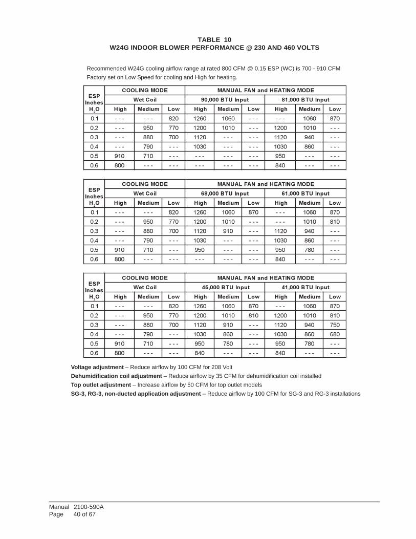
Manual 2100-590APage 40 of 67
TABLE 10W24G INDOOR BLOWER PERFORMANCE @ 230 AND 460 VOLTS
Recommended W24G cooling airflow range at rated 800 CFM @ 0.15 ESP (WC) is 700 - 910 CFMFactory set on Low Speed for cooling and High for heating.
Voltage adjustment – Reduce airflow by 100 CFM for 208 VoltDehumidification coil adjustment – Reduce airflow by 35 CFM for dehumidification coil installedTop outlet adjustment – Increase airflow by 50 CFM for top outlet modelsSG-3, RG-3, non-ducted application adjustment – Reduce airflow by 100 CFM for SG-3 and RG-3 installations
PSE
sehcnI
H2O
EDOMGNILOOC EDOMGNITAEHdnaNAFLAUNAM
lioCteW tupnIUTB000,09 tupnIUTB000,18
hgiH muideM woL hgiH muideM woL hgiH muideM woL
1.0 --- --- 028 0621 0601 --- --- 0601 078
2.0 --- 059 077 0021 0101 --- 0021 0101 ---
3.0 --- 088 007 0211 --- --- 0211 049 ---
4.0 --- 097 --- 0301 --- --- 0301 068 ---
5.0 019 017 --- --- --- --- 059 --- ---
6.0 008 --- --- --- --- --- 048 --- ---
PSE
sehcnI
H2O
EDOMGNILOOC EDOMGNITAEHdnaNAFLAUNAM
lioCteW tupnIUTB000,86 tupnIUTB000,16
hgiH muideM woL hgiH muideM woL hgiH muideM woL
1.0 --- --- 028 0621 0601 078 --- 0601 078
2.0 --- 059 077 0021 0101 --- --- 0101 018
3.0 --- 088 007 0211 019 --- 0211 049 ---
4.0 --- 097 --- 0301 --- --- 0301 068 ---
5.0 019 017 --- 059 --- --- 059 087 ---
6.0 008 --- --- --- --- --- 048 --- ---
PSE
sehcnI
H2O
EDOMGNILOOC EDOMGNITAEHdnaNAFLAUNAM
lioCteW tupnIUTB000,54 tupnIUTB000,14
hgiH muideM woL hgiH muideM woL hgiH muideM woL
1.0 --- --- 028 0621 0601 078 --- 0601 078
2.0 --- 059 077 0021 0101 018 0021 0101 018
3.0 --- 088 007 0211 019 --- 0211 049 057
4.0 --- 097 --- 0301 068 --- 0301 068 086
5.0 019 017 --- 059 087 --- 059 087 ---
6.0 008 --- --- 048 --- --- 048 --- ---
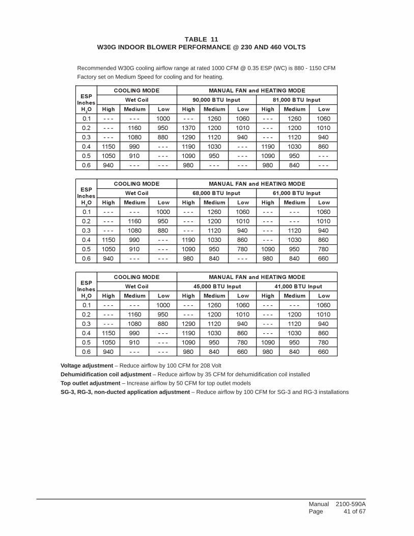
Manual 2100-590APage 41 of 67
TABLE 11W30G INDOOR BLOWER PERFORMANCE @ 230 AND 460 VOLTS
Recommended W30G cooling airflow range at rated 1000 CFM @ 0.35 ESP (WC) is 880 - 1150 CFMFactory set on Medium Speed for cooling and for heating.
Voltage adjustment – Reduce airflow by 100 CFM for 208 VoltDehumidification coil adjustment – Reduce airflow by 35 CFM for dehumidification coil installedTop outlet adjustment – Increase airflow by 50 CFM for top outlet modelsSG-3, RG-3, non-ducted application adjustment – Reduce airflow by 100 CFM for SG-3 and RG-3 installations
PSE
sehcnI
H2O
EDOMGNILOOC EDOMGNITAEHdnaNAFLAUNAM
lioCteW tupnIUTB000,09 tupnIUTB000,18
hgiH muideM woL hgiH muideM woL hgiH muideM woL
1.0 --- --- 0001 --- 0621 0601 --- 0621 0601
2.0 --- 0611 059 0731 0021 0101 --- 0021 0101
3.0 --- 0801 088 0921 0211 049 --- 0211 049
4.0 0511 099 --- 0911 0301 --- 0911 0301 068
5.0 0501 019 --- 0901 059 --- 0901 059 ---
6.0 049 --- --- 089 --- --- 089 048 ---
PSE
sehcnI
H2O
EDOMGNILOOC EDOMGNITAEHdnaNAFLAUNAM
lioCteW tupnIUTB000,86 tupnIUTB000,16
hgiH muideM woL hgiH muideM woL hgiH muideM woL
1.0 --- --- 0001 --- 0621 0601 --- --- 0601
2.0 --- 0611 059 --- 0021 0101 --- --- 0101
3.0 --- 0801 088 --- 0211 049 --- 0211 049
4.0 0511 099 --- 0911 0301 068 --- 0301 068
5.0 0501 019 --- 0901 059 087 0901 059 087
6.0 049 --- --- 089 048 --- 089 048 066
PSE
sehcnI
H2O
EDOMGNILOOC EDOMGNITAEHdnaNAFLAUNAM
lioCteW tupnIUTB000,54 tupnIUTB000,14
hgiH muideM woL hgiH muideM woL hgiH muideM woL
1.0 --- --- 0001 --- 0621 0601 --- --- 0601
2.0 --- 0611 059 --- 0021 0101 --- 0021 0101
3.0 --- 0801 088 0921 0211 049 --- 0211 049
4.0 0511 099 --- 0911 0301 068 --- 0301 068
5.0 0501 019 --- 0901 059 087 0901 059 087
6.0 049 --- --- 089 048 066 089 048 066
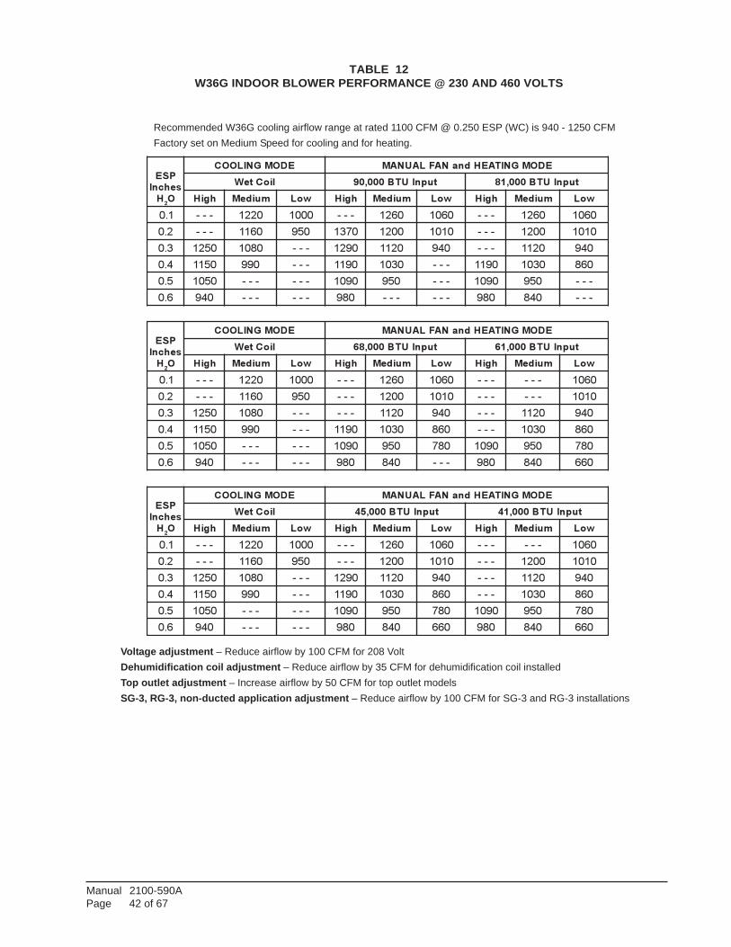
Manual 2100-590APage 42 of 67
TABLE 12W36G INDOOR BLOWER PERFORMANCE @ 230 AND 460 VOLTS
Recommended W36G cooling airflow range at rated 1100 CFM @ 0.250 ESP (WC) is 940 - 1250 CFMFactory set on Medium Speed for cooling and for heating.
Voltage adjustment – Reduce airflow by 100 CFM for 208 VoltDehumidification coil adjustment – Reduce airflow by 35 CFM for dehumidification coil installedTop outlet adjustment – Increase airflow by 50 CFM for top outlet modelsSG-3, RG-3, non-ducted application adjustment – Reduce airflow by 100 CFM for SG-3 and RG-3 installations
PSE
sehcnI
H2O
EDOMGNILOOC EDOMGNITAEHdnaNAFLAUNAM
lioCteW tupnIUTB000,09 tupnIUTB000,18
hgiH muideM woL hgiH muideM woL hgiH muideM woL
1.0 --- 0221 0001 --- 0621 0601 --- 0621 0601
2.0 --- 0611 059 0731 0021 0101 --- 0021 0101
3.0 0521 0801 --- 0921 0211 049 --- 0211 049
4.0 0511 099 --- 0911 0301 --- 0911 0301 068
5.0 0501 --- --- 0901 059 --- 0901 059 ---
6.0 049 --- --- 089 --- --- 089 048 ---
PSE
sehcnI
H2O
EDOMGNILOOC EDOMGNITAEHdnaNAFLAUNAM
lioCteW tupnIUTB000,86 tupnIUTB000,16
hgiH muideM woL hgiH muideM woL hgiH muideM woL
1.0 --- 0221 0001 --- 0621 0601 --- --- 0601
2.0 --- 0611 059 --- 0021 0101 --- --- 0101
3.0 0521 0801 --- --- 0211 049 --- 0211 049
4.0 0511 099 --- 0911 0301 068 --- 0301 068
5.0 0501 --- --- 0901 059 087 0901 059 087
6.0 049 --- --- 089 048 --- 089 048 066
PSE
sehcnI
H2O
EDOMGNILOOC EDOMGNITAEHdnaNAFLAUNAM
lioCteW tupnIUTB000,54 tupnIUTB000,14
hgiH muideM woL hgiH muideM woL hgiH muideM woL
1.0 --- 0221 0001 --- 0621 0601 --- --- 0601
2.0 --- 0611 059 --- 0021 0101 --- 0021 0101
3.0 0521 0801 --- 0921 0211 049 --- 0211 049
4.0 0511 099 --- 0911 0301 068 --- 0301 068
5.0 0501 --- --- 0901 059 087 0901 059 087
6.0 049 --- --- 089 048 066 089 048 066
Manual 2100-590APage 43 of 67
TABLE 13W42G INDOOR BLOWER PERFORMANCE @ 230 AND 460 VOLTS
Recommended W42G cooling airflow range at rated 1300 CFM @ .35 ESP (WC) is 1030 - 1480 CFMFactory set on Medium Speed for heating and cooling
Voltage adjustment – Reduce airflow by 130 CFM for 208 VoltTop outlet adjustment – Increase airflow by 65 CFM for top outlet modelsSG-5, RG-5, non-ducted application adjustment – Reduce airflow by 170 CFM for SG-5 and RG-5 installations
PSE
sehcnI
HsO
EDOMGNILOOC NAFLAUNAM dna EDOMGNITAEH
lioCteW tupnIUTB000,521 tupnIUTB000,311
hgiH muideM woL hgiH muideM woL hgiH muideM woL
01. --- 0251 0111 --- 0851 0811 --- 0851 0811
02. --- 0541 0501 0881 0151 --- --- 0151 0901
03. --- 0041 --- 0671 0641 --- --- 0641 ---
04. 0841 0921 --- 0761 0431 --- 0761 0431 ---
05. 0931 --- --- 0651 0421 --- 0651 0421 ---
06. 0721 --- --- 0341 0311 --- 0341 0311 ---
PSE
sehcnI
HsO
EDOMGNILOOC NAFLAUNAM dna EDOMGNITAEH
lioCteW UTB000,001 tupnIUTB000,09
hgiH muideM woL hgiH muideM woL hgiH muideM woL
01. --- 0651 0611 --- 0361 0321 --- 0361 0321
02. --- 0941 0901 --- 0651 0611 --- 0651 0611
03. --- 0441 0701 0181 0151 0411 --- 0151 0411
04. 0351 0331 --- 0271 0931 --- 0271 0931 0201
05. 0441 0121 --- 0161 0921 --- 0161 0921 079
06. 0231 --- --- 0841 0811 --- 0841 0811 ---
PSE
sehcnI
HsO
EDOMGNILOOC NAFLAUNAM dna EDOMGNITAEH
lioCteW tupnIUTB000,57 tupnIUTB000,86
hgiH muideM woL hgiH muideM woL hgiH muideM woL
01. --- 0061 0621 --- 0861 0821 --- 0861 0821
02. --- 0351 0911 --- 0161 0121 --- 0161 0121
03. --- 0841 0211 0681 0651 0911 --- 0651 0911
04. --- 0631 0011 0771 0441 0701 --- 0441 0701
05. 0941 0821 --- 0661 0431 079 0661 0431 079
06. 0731 --- --- 0351 0321 --- 0351 0321 ---
Manual 2100-590APage 44 of 67
TABLE 14W48G INDOOR BLOWER PERFORMANCE @ 230 AND 460 VOLTS
Recommended W48G cooling airflow range at rated 1550 CFM @ .20 ESP (WC) is 1250 - 1780 CFMFactory set on Medium Speed for cooling and Medium Speed for heating.
Voltage adjustment – Reduce airflow by 130 CFM for 208 VoltTop outlet adjustment – Increase airflow by 65 CFM for top outlet modelsSG-5, RG-5, non-ducted application adjustment – Reduce airflow by 170 CFM for SG-5 and RG-5 installations
PSE
sehcnI
HsO
EDOMGNILOOC NAFLAUNAM dna EDOMGNITAEH
lioCteW tupnIUTB000,521 tupnIUTB000,311
hgiH muideM woL hgiH muideM woL hgiH muideM woL
01. --- 0251 --- --- 0851 0811 --- 0851 0811
02. 0171 0541 --- 0881 0151 --- --- 0151 0111
03. 0061 0041 --- 0671 0641 --- --- 0641 0901
04. 0841 0921 --- 0761 0431 --- 0761 0431 ---
05. 0931 --- --- 0651 0421 --- 0651 0421 ---
06. 0721 --- --- 0341 --- --- 0341 0311 ---
PSE
sehcnI
HsO
EDOMGNILOOC NAFLAUNAM dna EDOMGNITAEH
lioCteW UTB000,001 tupnIUTB000,09
hgiH muideM woL hgiH muideM woL hgiH muideM woL
01. --- 0651 --- --- 0361 0321 --- 0361 0321
02. 0671 0941 --- --- 0651 0611 --- 0651 0611
03. 0361 0441 --- 0181 0151 0411 --- 0151 0411
04. 0351 0331 --- 0271 0931 --- 0271 0931 0201
05. 0441 0121 --- 0161 0921 --- 0161 0921 079
06. 0231 --- --- 0841 0811 --- 0841 0811 ---
PSE
sehcnI
HsO
EDOMGNILOOC NAFLAUNAM dna EDOMGNITAEH
lioCteW tupnIUTB000,57 tupnIUTB000,86
hgiH muideM woL hgiH muideM woL hgiH muideM woL
01. --- 0061 --- --- 0861 0821 --- 0861 0821
02. 5081 0351 --- --- 0161 0121 --- 0161 0121
03. 0861 0841 --- 0681 0651 0911 --- 0651 0911
04. 0851 0631 --- 0771 0441 0701 --- 0441 0701
05. 0941 0821 --- 0661 0431 079 0661 0431 079
06. 0731 --- --- 0351 0321 --- 0351 0321 ---
Manual 2100-590APage 45 of 67
TABLE 15W60G INDOOR BLOWER PERFORMANCE @ 230 AND 460 VOLTS
Recommended W60G cooling airflow range at rated 1650 CFM @ .30 ESP (WC) is 1360 - 1850 CFMFactory set on High Speed for cooling and Medium Speed for heating.
Voltage adjustment – Reduce airflow by 130 CFM for 208 VoltTop outlet adjustment – Increase airflow by 65 CFM for top outlet modelsSG-5, RG-5, non-ducted application adjustment – Reduce airflow by 170 CFM for SG-5 and RG-5 installations
PSE
sehcnI
HsO
EDOMGNILOOC NAFLAUNAM dna EDOMGNITAEH
lioCteW tupnIUTB000,521 tupnIUTB000,311
hgiH muideM woL hgiH muideM woL hgiH muideM woL
01. 0081 0251 --- --- 0851 0811 --- 0851 0811
02. 0171 0541 --- 0881 0151 --- --- 0151 0111
03. 0061 0041 --- 0671 0641 --- --- 0641 0901
04. 0841 --- --- 0761 0431 --- 0761 0431 ---
05. 0931 --- --- 0651 0421 --- 0651 0421 ---
06. --- --- --- 0341 --- --- 0341 0311 ---
PSE
sehcnI
HsO
EDOMGNILOOC NAFLAUNAM dna EDOMGNITAEH
lioCteW UTB000,001 tupnIUTB000,09
hgiH muideM woL hgiH muideM woL hgiH muideM woL
01. 0681 0651 --- --- 0361 0321 --- 0361 0321
02. 0671 0941 --- --- 0651 0611 --- 0651 0611
03. 0361 0441 --- 0181 0151 0411 --- 0151 0411
04. 0351 0331 --- 0271 0931 --- 0271 0931 0201
05. 0441 --- --- 0161 0921 --- 0161 0921 079
06. 0231 --- --- 0841 0811 --- 0841 0811 ---
PSE
sehcnI
HsO
EDOMGNILOOC NAFLAUNAM dna EDOMGNITAEH
lioCteW tupnIUTB000,57 tupnIUTB000,86
hgiH muideM woL hgiH muideM woL hgiH muideM woL
01. 0191 0061 --- --- 0861 0821 --- 0861 0821
02. 5081 0351 --- --- 0161 0121 --- 0161 0121
03. 0861 0841 --- 0681 0651 0911 --- 0651 0911
04. 0851 0631 --- 0771 0441 0701 --- 0441 0701
05. 0941 --- --- 0661 0431 079 0661 0431 079
06. 0731 --- --- 0351 0321 --- 0351 0321 ---
Manual 2100-590APage 46 of 67
TABLE 16INTEGRATED FURNACE AND BLOWER CONTROL OPERATION
LORTNOCECNEUQESNOITINGI
ecruoSnoitingI ISDCAV42
gnisneSemalF etomeR
sgnimiT
-------
-----
--
egruperPegruptsoP
egruplairt-retnIdoirepgnivorphctiwserusserP
noitingirofslairTnoitingiroflairT
tuokcolecneuqesnoitingI
yaled-norewolbtaeHyaled-fforewolbtaeHyaled-norewolblooCyaled-fforewolblooCsnoitareponaflaunaM
noitarepolortnoctimilhgiHnoitarepohctiwstuolloremalF
510351063706-
03,09706
sdnoces)"no"evlaverofebdetanimretelcycfi0(sdnoces
sdnocessdnoces
ecneuqesnoitingirepemalfevorpotemitlatotsdnoces
teserotua,)noitingirofslairt3retfa(setunimgninepoybdoireptuokcoletunim06ehtgnirudteserebnac
eromrosdnoces3roftiucrictatsomreht)ffoselcycrotinginehwstratsgnimit(sdnoces021tatesyrotcaf;elbatcelessdnocs051,021
sdnocessdnoces
gnirudffoselcycdnadeepsgnitaehdetcelesnosetarepO.ecneuqesputratsrenrubronoitingi
.1etoNeeS.tratserecneuqesnoitingi,tesercitamotuAyllaunamsihctiwsretfadetaitiniecneuqesnotingi,teserlaunaM
.1etoNeeS.teser
:1ETON yaledruoh1aeblliwerehttaehrofllacneviganopirttimilhtruofehtretfAemalfrohctiwstimilhgihrehtieretfA.tratserlliwecneuqesnoitingiehterofebdnaegruptsopdnoces03ehtrofetarepolliwrecudniehtnoitautcahctiwstuollor
naFlaunaMnofI.yaledffodetcelesehtrofetarepolliwrewolbriatrofmoceht.etarepooteunitnoclliwrewolbriatrofmoceht,noitarepo
STINUYTEFAS
tuolloR/timilhgiHhctiwserusserP
tloV42niTSPSkcehctratsefas,TSPS
LORTNOCNAFTROFMOC
naFdeepSgnitaeHnoitarepolamroN
yaledNO-
yaledFFO-
noitarepOtimiL
esneSemalF
03
3
dezigrene-edretinginehwstratsgnimiT.dexifsdnoces
09otdegnahcebnacdradnatssdnoces021-sgnimitelbatceles.sdnoces051ro
NEPOtimilnehwNOSESOLCtimilnehwyaledFFOretfaFFO
desnessiemalffiNO dna .taehrofllaconsiereht
naFdeepSgnilooC- yaledNO
yaledFFO-
7
06
sdnoces
sdnoces
naFlaunaM nafeht,loocrofllacnehW.deepsGNITAEHnoylsuounitnocNO,deifsitastatsomrehtnehwnehT.deepsGNILOOCotsehctiwsFFOGNILOOCretfadeepsGNITAEHotkcabsehctiwsnafeht
.yaled
ROTACIDNICITSONGAID
:swollofsastluafmetsysetacidniotdedivorpsiDELderA
sedomnafrolooc,taehrofllac,ybdnatsniyakolortnoC-NOydaetS.lortnocnoesufA3kcehcoslA.rewoponrotluaflortnoclanretnI-FFOydaetS
stuopordemalfronoitingideliafoteudtuokcoL-hsalf1norecudnihtiwnepohctiwserusserP-sehsalf2
fforecudnihtiwdesolcsihctiwserusserP-sehsalf3neposihctiwstimiL-sehsalf4
desolcevlavsaghtiwdetcetedemalF-sehsalf5remitgnigats/elcyctrohsmorfdeyaledtuptuorosserpmoC-sehsalf6
.sedochsalfneewtebesuapsdnoces0.2htiwffosdnoces52.0,nosdnoces52.0sietarhsalfehT.sedochsalfneewtebesuapsdnoces0.2htiwffosdnoces52.0,nosdnoes52.0sietarhsalfehT
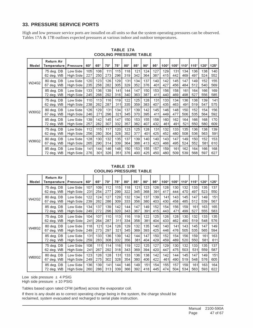
Manual 2100-590APage 47 of 67
33. PRESSURE SERVICE PORTSHigh and low pressure service ports are installed on all units so that the system operating pressures can be observed.Tables 17A & 17B outlines expected pressures at various indoor and outdoor temperatures.
TABLE 17ACOOLING PRESSURE TABLE
TABLE 17BCOOLING PRESSURE TABLE
Low side pressure ± 4 PSIGHigh side pressure ± 10 PSIG
Tables based upon rated CFM (airflow) across the evaporator coil.If there is any doubt as to correct operating charge being in the system, the charge should bereclaimed, system evacuated and recharged to serial plate instruction.
ledoM
riAnruteR
erutarepmeT erusserP °06 °56 °07 °57 °08 °58 °09 °59 °001 °501 °011 °511 °021 °521
2G42W
BD.ged57
BW.ged26
ediSwoL
ediShgiH
501
722
801
052
111
372
511
692
811
913
121
243
421
463
721
783
921
514
131
244
431
964
631
794
831
425
041
255
BD.ged08
BW.ged76
ediSwoL
ediShgiH
021
532
321
852
621
282
921
503
131
923
431
253
731
673
041
104
241
724
541
654
741
484
941
215
251
045
551
965
BD.ged58
BW.ged27
ediSwoL
ediShgiH
331
542
631
862
931
292
141
613
441
043
741
363
051
783
351
114
651
044
851
964
161
894
461
725
661
655
961
585
2G03W
BD.ged57
BW.ged26
ediSwoL
ediShgiH
011
832
311
262
611
782
911
113
221
533
521
953
821
383
131
704
331
534
431
364
631
194
831
915
931
745
141
575
BD.ged08
BW.ged76
ediSwoL
ediShgiH
621
642
921
172
131
692
431
123
731
543
931
073
241
593
541
114
641
944
841
774
051
605
251
535
451
465
651
295
BD.ged58
BW.ged27
ediSwoL
ediShgiH
931
752
241
282
541
703
741
233
051
753
351
283
551
704
851
234
061
164
261
194
461
125
661
055
861
085
071
906
2G63W
BD.ged57
BW.ged26
ediSwoL
ediShgiH
211
652
511
082
711
403
021
823
321
253
521
773
821
104
131
524
231
254
331
084
531
805
631
635
831
365
931
195
BD.ged08
BW.ged76
ediSwoL
ediShgiH
821
562
031
092
231
413
531
933
731
463
931
883
041
314
041
324
341
664
741
594
941
425
051
255
251
185
351
016
BD.ged58
BW.ged27
ediSwoL
ediShgiH
141
672
441
103
641
623
841
153
051
673
351
004
551
524
751
054
951
084
161
905
261
935
461
865
661
795
861
726
ledoM
riAnruteR
erutarepmeT erusserP °06 °56 °07 °57 °08 °58 °09 °59 °001 °501 °011 °511 °021 °521
2G24W
BD.ged57
BW.ged26
ediSwoL
ediShgiH
701
132
901
452
211
772
511
992
811
223
121
543
321
863
621
193
821
714
031
444
231
074
331
794
531
325
731
055
BD.ged08
BW.ged76
ediSwoL
ediShgiH
221
932
421
262
721
682
921
903
231
333
431
653
731
083
931
304
141
034
341
854
541
584
741
215
941
935
151
765
BD.ged58
BW.ged27
ediSwoL
ediShgiH
431
942
731
272
931
692
241
023
441
343
741
763
941
193
251
514
451
344
651
174
951
994
161
725
361
555
561
385
2G84W
BD.ged57
BW.ged26
ediSwoL
ediShgiH
401
142
701
462
011
782
311
113
611
433
911
853
221
183
521
404
621
334
821
264
031
094
231
915
331
845
531
675
BD.ged08
BW.ged76
ediSwoL
ediShgiH
811
942
121
372
421
792
621
123
921
543
231
963
531
393
041
524
041
644
141
674
341
505
541
535
741
565
941
495
BD.ged58
BW.ged27
ediSwoL
ediShgiH
131
952
331
382
631
803
931
233
241
653
441
183
741
404
051
924
251
954
451
984
651
025
951
055
161
185
361
116
2G06W
BD.ged57
BW.ged26
ediSwoL
ediShgiH
801
142
111
762
411
292
611
813
911
343
221
963
521
493
721
024
921
744
031
574
231
305
331
135
531
955
731
785
BD.ged08
BW.ged76
ediSwoL
ediShgiH
321
942
621
572
821
203
131
823
331
453
631
083
831
604
241
224
241
164
441
094
541
915
741
845
941
675
151
506
BD.ged58
BW.ged27
ediSwoL
ediShgiH
631
062
931
682
141
313
441
933
641
663
941
293
151
814
451
544
551
474
751
405
951
435
161
365
361
395
461
226
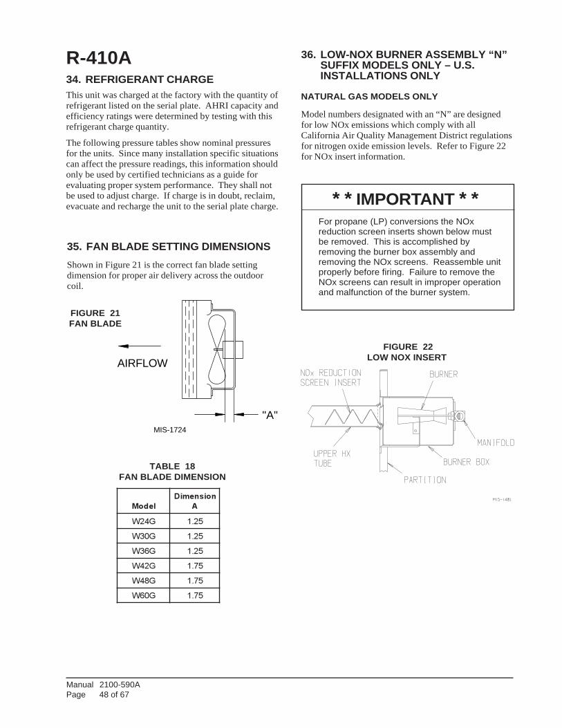
Manual 2100-590APage 48 of 67
"A"
AIRFLOW
MIS-1724
35. FAN BLADE SETTING DIMENSIONSShown in Figure 21 is the correct fan blade settingdimension for proper air delivery across the outdoorcoil.
ledoM
noisnemiD
A
G42W 52.1
G03W 52.1
G63W 52.1
G24W 57.1
G84W 57.1
G06W 57.1
TABLE 18FAN BLADE DIMENSION
FIGURE 21FAN BLADE
36. LOW-NOX BURNER ASSEMBLY “N”SUFFIX MODELS ONLY – U.S.INSTALLATIONS ONLY
NATURAL GAS MODELS ONLY
Model numbers designated with an “N” are designedfor low NOx emissions which comply with allCalifornia Air Quality Management District regulationsfor nitrogen oxide emission levels. Refer to Figure 22for NOx insert information.
* * IMPORTANT * *For propane (LP) conversions the NOxreduction screen inserts shown below mustbe removed. This is accomplished byremoving the burner box assembly andremoving the NOx screens. Reassemble unitproperly before firing. Failure to remove theNOx screens can result in improper operationand malfunction of the burner system.
FIGURE 22LOW NOX INSERT
R-410A34. REFRIGERANT CHARGEThis unit was charged at the factory with the quantity ofrefrigerant listed on the serial plate. AHRI capacity andefficiency ratings were determined by testing with thisrefrigerant charge quantity.
The following pressure tables show nominal pressuresfor the units. Since many installation specific situationscan affect the pressure readings, this information shouldonly be used by certified technicians as a guide forevaluating proper system performance. They shall notbe used to adjust charge. If charge is in doubt, reclaim,evacuate and recharge the unit to the serial plate charge.
Manual 2100-590APage 49 of 67
INDEXWIRING DIAGRAMS
and LADDER DIAGRAMS
tinU.oNledoM
cisaBmargaiDgniriW
launaM.oNegaP
cisaBmargaiDreddaL
launaM.oNegaP
A-2G42W A951-5804 05 061-5804 15
B-2G42W A752-5804 25 852-5804 35
C-2G42W A083-5804 45 183-5804 55
A-2G03W A161-5804 65 261-5804 75
B-2G03W A952-5804 85 062-5804 95
C-2G03W A283-5804 06 383-5804 16
A-2G63W A161-5804 65 261-5804 75
B-2G63W A952-5804 85 062-5804 95
C-2G63W A283-5804 06 383-5804 16
A-2G24W A161-5804 65 261-5804 75
B-2G24W A952-5804 85 062-5804 95
C-2G24W A283-5804 06 383-5804 16
A-2G84W A161-5804 65 261-5804 75
B-2G84W A952-5804 85 062-5804 95
C-2G84W A283-5804 06 383-5804 16
A-2G06W A361-5804 26 461-5804 36
B-2G06W A162-5804 46 262-5804 56
C-2G06W A483-5804 66 583-5804 76
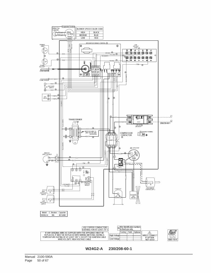
Manual 2100-590APage 50 of 67
W24G2-A 230/208-60-1
LPC
CC
HP
C
Y
ALR C
LPC
MIN
UT
ES
4
235
R
1
32ORANGE
BLACK
43RED
38
39
38
42
39
BLA
CK
/WH
ITE
BLA
CK
BLA
CK
/WH
ITE
SPEED 150
208/230-60-1
(OPT.)
135
BLA
CK
/WH
ITE
BLACK
BLA
CK
120
FUSE
BLA
CK
BLACK
P3
BROWN
GRAY
BR
OW
N
BLA
CK
/WH
ITE
BLACK
USE COPPER CONDUCTORSSUITABLE FOR AT LEAST 75° C
TERM. BLOCK
BLA
CK
PINK
PINK
L2
L1
BLU
E
BLUE
BLUE
1 2 3
4 5 6
8 97
1210
BLU
E
11
BLU
E
A
BLU
E
A
PURPLE
PURPLE
NOC
MV
MV
YELLOW
YE
LLO
W/R
ED
YELLOW
YELLOW
YE
LLO
W
YELLOW
YE
LLOW
Brown
Brown
L2
T1
RED
RED
RE
D
RED/WHITE
L1
TRANSFORMER
T2
COMPRESSOR15
RE
D
MOVE RED WIRE TO 208V TAP FOR 208V
OPERATION
RE
D/W
HIT
E
for Bard use only.
35
Wire Identification numbers
RED
99
32
RED/WHITE
32
RED
32
BLACK
R
C
240V
DRAFT BLOWER
2PL
11
208V
COM
BR
RE
D
Indoor
INDUCED
Fan Motor
Indoor Fan
CONTACTOR
Capacitor
40
Evaporator Section
RED
RED
GROUND TERMINAL
40
35
RE
D
C
MODULE
23
PRESSURE
COMPRESSORCONTROL
HE
RM
SWITCH
SWITCH
MOTOR
LOW
21
PRESSURE
HIGH
Compressor
CAPACITOR
OUTDOOR FAN
11
INTEGRATED FURNACE CONTROL
FAN
REPLACED, IT MUST BE REPLACED WITH WIRING MATERIAL HAVING A TEMPERATURE RATING OF AT LEAST 105° C EXCEPT THE IGNITION CABLE
WHICH IS 250°C HIGH VOLTAGE CABLE
VOLTAGE
BREAKER
STRIP
LOW
CIRCUIT
13
IF ANY ORIGINAL WIRE AS SUPPLIED WITH THE APPLIANCE MUST BE
16
WIRES CONNECTIF OPTION NOT USED
32
37
59
GAS VALVE
32 32
37
35
32
32
32
35
PRIMARY
32
ROLLOUT
SPARK IGNITOR
LIMIT
FLAME
SWITCH
35
SR
C
Bard Mfg. Co.
Bryan, Ohio
Low Voltage
High Voltage
FLAME SENSOR
PRESSURE
Optional
32
Field
36
Factory
32
LOW AMBIENTCONTROL (OPT.)
44
A
34
20
18
32
32
BLOWER SPEED COLOR CODE
HIGH BLACK
MEDIUM BLUE
LOW RED
4085-159 A
Model C. Breaker Capacitor
W24G2-A 30A 40+5/440
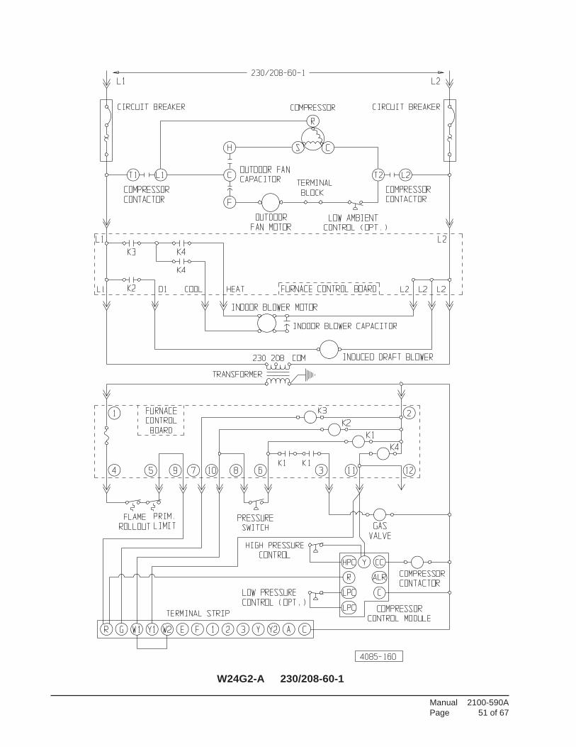
Manual 2100-590APage 51 of 67
W24G2-A 230/208-60-1
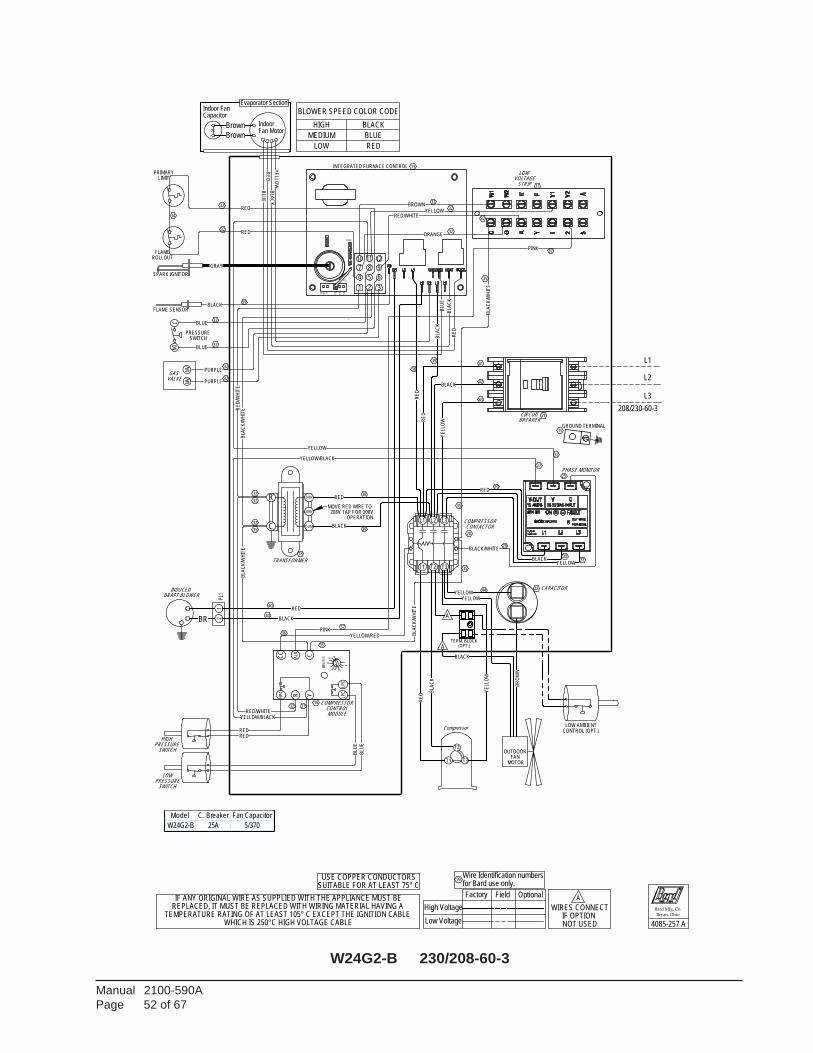
Manual 2100-590APage 52 of 67
W24G2-B 230/208-60-3
LPC
CC
HP
C
Y
ALR C
LPC
MIN
UT
ES
4
235
R
1
32ORANGE
MODULE
HIGH
Compressor
CONTROL
SWITCH
MOTOR
COMPRESSOR
PRESSURE
23
REPLACED, IT MUST BE REPLACED WITH WIRING MATERIAL HAVING A TEMPERATURE RATING OF AT LEAST 105° C EXCEPT THE IGNITION CABLE
WHICH IS 250°C HIGH VOLTAGE CABLE
OUTDOOR FAN
INTEGRATED FURNACE CONTROL 13
VOLTAGESTRIP 11
LOW
CIRCUITBREAKER
CAPACITOR
21
LOWPRESSURE
SWITCH
IF ANY ORIGINAL WIRE AS SUPPLIED WITH THE APPLIANCE MUST BE
16
WIRES CONNECTIF OPTION NOT USED
35
GAS VALVE
32 27
37
35
32
32
32
32
59
PRIMARY
ROLLOUT
SPARK IGNITOR
LIMIT
32
FLAME
FLAME SENSOR
36
PRESSURE SWITCH
T3T1
35
T2
Bard Mfg. Co.
Bryan, Ohio
Low Voltage
High Voltage
OptionalFieldFactory
32
LOW AMBIENTCONTROL (OPT.)
44
A
34
20
18
32
32
32
35
37
BLOWER SPEED COLOR CODE
HIGH BLACK
MEDIUM BLUE
LOW RED
4085-257 A
(OPT.)
SPEED 150
135
120
BLA
CK
BLA
CK
/WH
ITE
FUSE
BLACK
BLACK/WHITE
BLACK
BLA
CK
BLACK
P3
BROWN
GRAY
BR
OW
N
BLA
CK
/WH
ITE
BLACK
BLACK
208/230-60-3
BLA
CK
BLA
CK
/WH
ITE
BLA
CK
/WH
ITE
USE COPPER CONDUCTORSSUITABLE FOR AT LEAST 75° C
TERM. BLOCK
BLA
CK
PINK
PINK
BLUE
BLUE
1 2 3
4 5 6
8 97
1210 11
BLU
E
BLU
E
L3
L1
L2
A
BLU
E
A
BLU
E
PURPLE
PURPLE
MV
NOC
MV
YELLOW
YELLOW
YE
LLO
W
YELLOW
YELLOW/BLACK
YELLOW/RED
YELLOW
YE
LLOW
YELLOW
YE
LLO
W
YELLOW/BLACK
Brown
Brown
RED
RE
D
RED/WHITE
RED
RE
D/W
HIT
E
for Bard use only.Wire Identification numbers
99
RED32
RED/WHITE
32
RED
32
40BLACK
RED
R
C
240V
208V
COM
DRAFT BLOWER
2PL
11
BR
RE
D
INDUCED
Fan MotorIndoor
Capacitor
Evaporator SectionIndoor Fan
CONTACTOR
TRANSFORMER
COMPRESSOR
40
OPERATION208V TAP FOR 208V
MOVE RED WIRE TO
35
RE
D
GROUND TERMINAL
L1 L2
T1 T2
L3
T3
15
PHASE MONITOR 25
RED
28
RED29
3031
41
42
43
RE
D
38
39
32
27
38
39
RE
D
Model C. Breaker Fan Capacitor
W24G2-B 25A 5/370
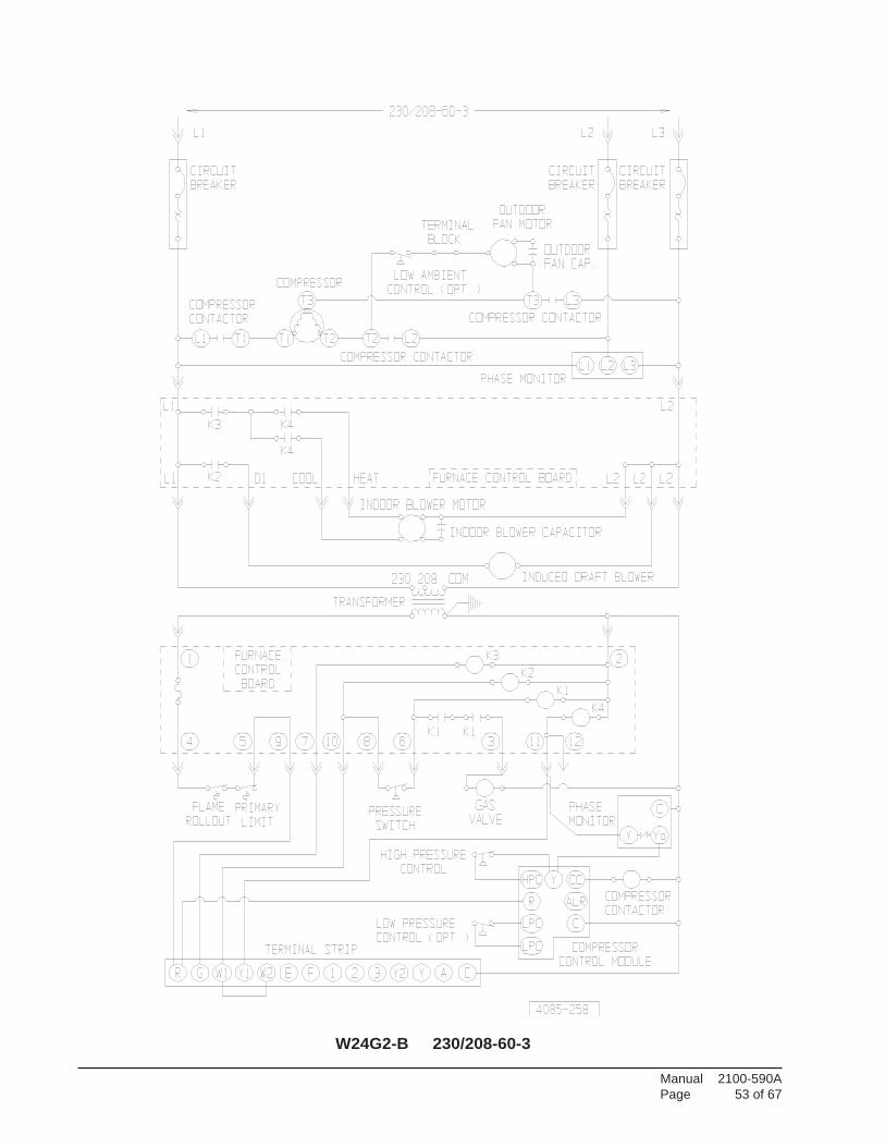
Manual 2100-590APage 53 of 67
W24G2-B 230/208-60-3
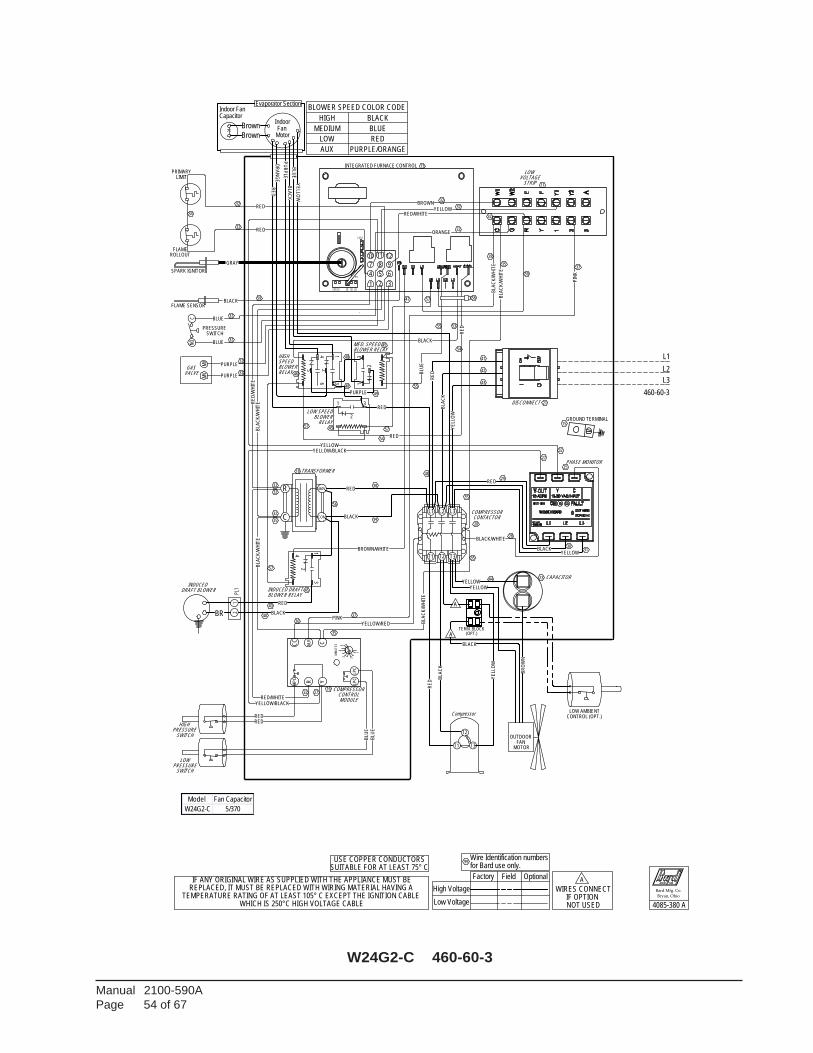
Manual 2100-590APage 54 of 67
W24G2-C 460-60-3
32ORANGE
LPC
CC
HP
C
Y
ALR C
LPC
MIN
UT
ES
4
235
R
1
BLA
CK
/WH
ITE
SPEED 150
135
120
BLACK
BLA
CK
/WH
ITE
FUSE
BLA
CK
BLACK
BLACK/WHITE
BLA
CK
BLACK
P3
BROWN
GRAY
BR
OW
N
BLA
CK
/WH
ITE
BLACK
(OPT.)
460-60-3
BLA
CK
/WH
ITE
BLA
CK
/WH
ITE
USE COPPER CONDUCTORSSUITABLE FOR AT LEAST 75° C
TERM. BLOCK
BLACK
PINK
PIN
K
BLUE
BLUE
1 2 3
4 5 6
8 97
1210 11
BLU
EL2
BLU
E
L3
A
A
BLU
E
BLA
CK
YE
LLOW
PU
RP
LE
BLU
E
PURPLE
PURPLE
PURPLE
MV
NOC
MV
YELLOW
YELLOW
YE
LLO
W
YELLOW
YELLOW/BLACK
YELLOW/RED
YELLOW
YELLOW
YE
LLO
WYELLOW/BLACK
Brown
Brown
BROWN/WHITE
RED
RE
D
RED/WHITE
RED
RE
D/W
HIT
E
for Bard use only.Wire Identification numbers
99
RED32
RED/WHITE
32
RED
32
40BLACK
RED
R
C
460V
COM
DRAFT BLOWER
2PL
11
BR
INDUCED
MotorFan
Capacitor
Evaporator SectionIndoor Fan
CONTACTOR
40
TRANSFORMER
COMPRESSOR
Indoor
35
GROUND TERMINAL
L1 L2
T1 T2
L3
T3
PHASE MONITOR
15
RED
28
RED29
3031
41
42
43
RE
D
38
39
32
2
31
5
46
RED
27R
ED
50
BLOWER RELAYMED. SPEED
RELAY BLOWER
BLOWER RELAYINDUCED DRAFT
LOW SPEED
28
RELAYBLOWERSPEED HIGH
54
56
58
RED
MODULE
HIGH
Compressor
CONTROL
SWITCH
MOTOR
COMPRESSOR
PRESSURE
23
REPLACED, IT MUST BE REPLACED WITH WIRING MATERIAL HAVING A TEMPERATURE RATING OF AT LEAST 105° C EXCEPT THE IGNITION CABLE
WHICH IS 250°C HIGH VOLTAGE CABLE
OUTDOOR FAN
INTEGRATED FURNACE CONTROL 13
STRIP 11
LOW VOLTAGE
DISCONNECT
CAPACITOR
21
LOWPRESSURE
SWITCH
IF ANY ORIGINAL WIRE AS SUPPLIED WITH THE APPLIANCE MUST BE
16
WIRES CONNECTIF OPTION NOT USED
L1
OR
AN
GE
55
53
GAS VALVE
32 27
37
35
32
32
32
32
59
PRIMARY
ROLLOUT
SPARK IGNITOR
LIMIT
32
FLAME
FLAME SENSOR
36
PRESSURE SWITCH
T3T1
T2
Bard Mfg. Co.
Bryan, Ohio
4085-380 ALow Voltage
High Voltage
OptionalFieldFactory
32
LOW AMBIENTCONTROL (OPT.)
44
A
34
20
18
32
32
32
35
37
2
335
1
2
31
2
35
3
4
48
1
57
57
48
57
48
49
45
45
47
57
45
46
25
RE
D
54
55
BLOWER SPEED COLOR CODE
HIGH BLACK
MEDIUM BLUE
LOW RED
AUX PURPLE/ORANGE
Model Fan Capacitor
W24G2-C 5/370

Manual 2100-590APage 55 of 67
W24G2-C 460-60-3
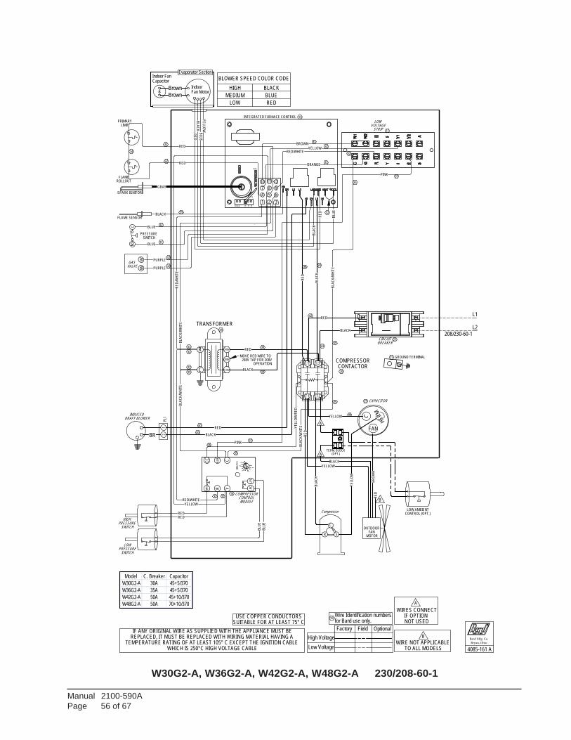
Manual 2100-590APage 56 of 67
W30G2-A, W36G2-A, W42G2-A, W48G2-A 230/208-60-1
LPC
CC
HP
C
Y
ALR C
LPC
MIN
UT
ES
4
235
R
1
WIRE NOT APPLICABLE TO ALL MODELS
B
32ORANGE
BLACK39
38
42
43RED
38
39
C
MODULE
HE
RM
FAN
HIGH
Compressor
CONTROL
SWITCH
MOTOR
COMPRESSOR
PRESSURE
23
REPLACED, IT MUST BE REPLACED WITH WIRING MATERIAL HAVING A TEMPERATURE RATING OF AT LEAST 105° C EXCEPT THE IGNITION CABLE
WHICH IS 250°C HIGH VOLTAGE CABLE
OUTDOOR FAN
INTEGRATED FURNACE CONTROL 13
VOLTAGESTRIP 11
LOW
CIRCUITBREAKER
CAPACITOR
21
LOWPRESSURE
SWITCH
IF ANY ORIGINAL WIRE AS SUPPLIED WITH THE APPLIANCE MUST BE
16
WIRES CONNECTIF OPTION NOT USED
37
A
B
GAS VALVE
32 32
37
35
32
32
32
32
59
PRIMARY
ROLLOUT
SPARK IGNITOR
LIMIT
32
FLAME
FLAME SENSOR
36
PRESSURE SWITCH
SR
C
35
Bard Mfg. Co.
Bryan, Ohio
Low Voltage
High Voltage
OptionalField
32
Factory
44
LOW AMBIENTCONTROL (OPT.)
34
20
18
32
32
32
35
BLOWER SPEED COLOR CODE
HIGH BLACK
MEDIUM BLUE
LOW RED
4085-161 A
BLA
CK
SPEED 150
135
120
BLACK
BLA
CK
FUSE
BLA
CK
/WH
ITE
BLA
CK
/WH
ITE
BLA
CK
/WH
ITE
BLA
CK
BLACK
P3
BROWN
GRAY
BR
OW
N
BLA
CK
/WH
ITE
BLACK
(OPT.)
208/230-60-1
USE COPPER CONDUCTORSSUITABLE FOR AT LEAST 75° C
TERM. BLOCK
BLA
CK
PINK
PINK
BLU
E
BLUE
BLUE
1 2 3
4 5 6
8 97
1210 11
BLU
E
BLU
E
L1
L2
A
BLU
E
A
PURPLE
PURPLE
MV
NOC
MV
YELLOW
YELLOW
YE
LLO
W
YELLOW
YELLOW
YE
LLO
W/R
ED
YE
LLOW
Brown
Brown
35
RED
RE
D
RE
D
RED/WHITE
RED
RE
D/W
HIT
E
RE
D
for Bard use only.Wire Identification numbers
99
RED32
RED/WHITE
32
RED
32
40BLACK
RED40
GROUND TERMINAL
R
C
240V
208V
COM
DRAFT BLOWER
2PL
11
BR
RE
D
INDUCED
Fan MotorIndoor
Capacitor
Evaporator SectionIndoor Fan
CONTACTOR
RED
TRANSFORMER
COMPRESSOR15
OPERATION208V TAP FOR 208V
MOVE RED WIRE TO
35
RE
D
L1 L2
T1 T2
52
Model C. Breaker Capacitor
W30G2-A 30A 45+5/370
W36G2-A 35A 45+5/370
W42G2-A 50A 45+10/370
W48G2-A 50A 70+10/370
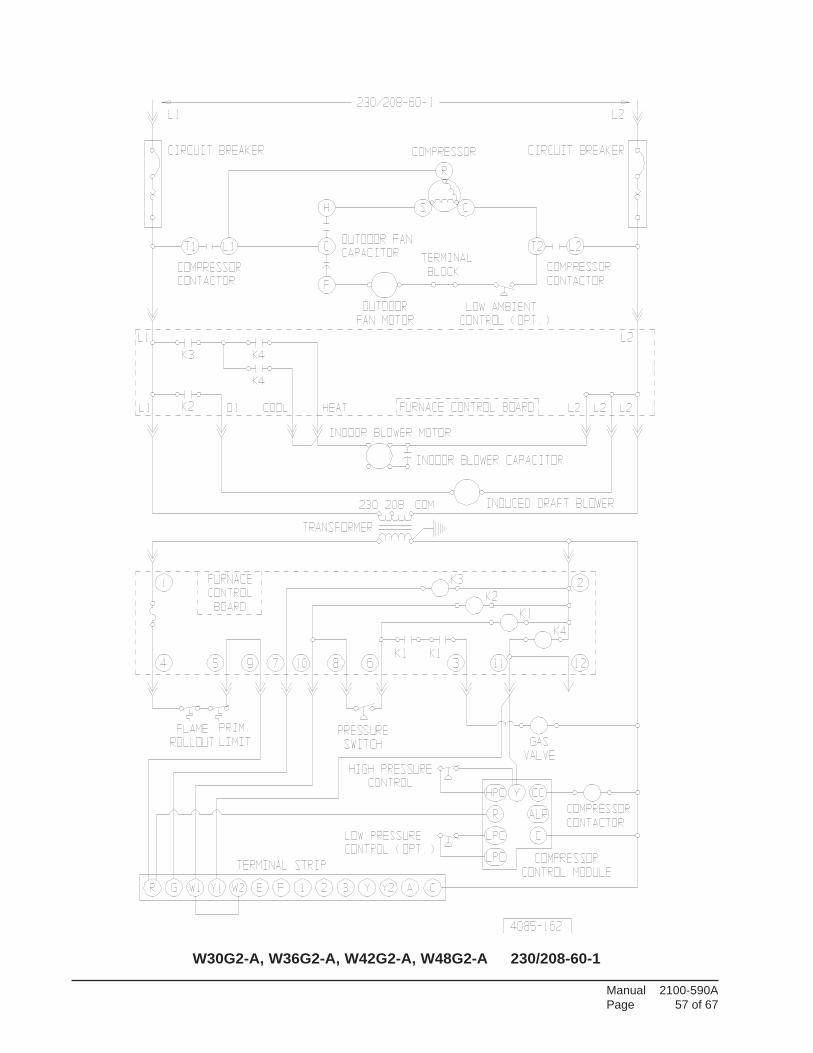
Manual 2100-590APage 57 of 67
W30G2-A, W36G2-A, W42G2-A, W48G2-A 230/208-60-1
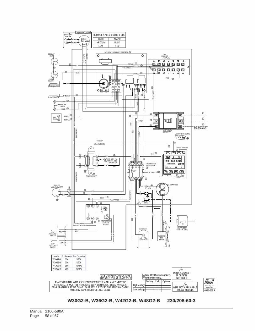
Manual 2100-590APage 58 of 67
W30G2-B, W36G2-B, W42G2-B, W48G2-B 230/208-60-3
LPC
CC
HP
C
Y
ALR C
LPC
MIN
UT
ES
4
235
R
1
IF OPTION WIRES CONNECT
NOT USED
A
32ORANGE
(OPT.)
SPEED 150
135
120
BLA
CK
BLA
CK
/WH
ITE
FUSE
BLACK
BLACK/WHITE
BLACK
BLA
CK
BLACK
P3
BROWN
GRAY
BR
OW
N
BLA
CK
/WH
ITE
BLACK
BLACK
208/230-60-3
BLA
CK
BLA
CK
/WH
ITE
BLA
CK
/WH
ITE
USE COPPER CONDUCTORSSUITABLE FOR AT LEAST 75° C
TERM. BLOCK
BLA
CK
PINK
PINK
BLUE
BLUE
1 2 3
4 5 6
8 97
1210 11
BLU
E
BLU
EL1
L3
L2
A
BLU
E
A
BLU
E
PURPLE
PURPLE
MV
NOC
MV
YELLOW
YELLOW
YE
LLO
W
YELLOW
YELLOW/BLACK
YELLOW/RED
YELLOW
YE
LLOW
YELLOW
YE
LLO
W
YELLOW/BLACK
Brown
Brown
RED
RE
D
RE
D
RED/WHITE
RED
RE
D/W
HIT
E
WIRE NOT APPLICABLE
for Bard use only.Wire Identification numbers
TO ALL MODELS
B
99
RED32
RED/WHITE
32
RED
32
40BLACK
RED
R
C
240V
208V
COM
DRAFT BLOWER
2PL
11
BR
RE
D
INDUCED
Fan MotorIndoor
Capacitor
Evaporator SectionIndoor Fan
CONTACTOR
TRANSFORMER
COMPRESSOR
40
OPERATION208V TAP FOR 208V
MOVE RED WIRE TO
35
RE
D
GROUND TERMINAL
L1 L2
T1 T2
L3
T3
15
PHASE MONITOR 25
RED
28
RED29
3031
41
42
43
RE
D
38
39
32
27
38
RE
D
39
52
B
SWITCH
HIGH
SWITCH
MOTOR
MODULE
PRESSURE
23
REPLACED, IT MUST BE REPLACED WITH WIRING MATERIAL HAVING A TEMPERATURE RATING OF AT LEAST 105° C EXCEPT THE IGNITION CABLE
WHICH IS 250°C HIGH VOLTAGE CABLE
OUTDOOR FAN
INTEGRATED FURNACE CONTROL 13
VOLTAGESTRIP 11
LOW
CIRCUITBREAKER
CAPACITOR
21
LOWPRESSURE
IF ANY ORIGINAL WIRE AS SUPPLIED WITH THE APPLIANCE MUST BE
16 COMPRESSORCONTROL
Compressor
35
GAS VALVE
32 27
37
35
32
32
32
32
59
PRIMARY
ROLLOUT
SPARK IGNITOR
LIMIT
32
FLAME
FLAME SENSOR
36
PRESSURE SWITCH
T3T1
T2
Bard Mfg. Co.
35
Bryan, Ohio
Low Voltage
High Voltage
OptionalField
32
Factory
44
LOW AMBIENTCONTROL (OPT.)
34
20
18
32
32
32
35
37
BLOWER SPEED COLOR CODE
HIGH BLACK
MEDIUM BLUE
LOW RED
4085-259 A
Model C. Breaker Fan Capacitor
W30G2-B 25A 5/370
W36G2-B 35A 5/370
W42G2-B 35A 10/370
W48G2-B 35A 10/370
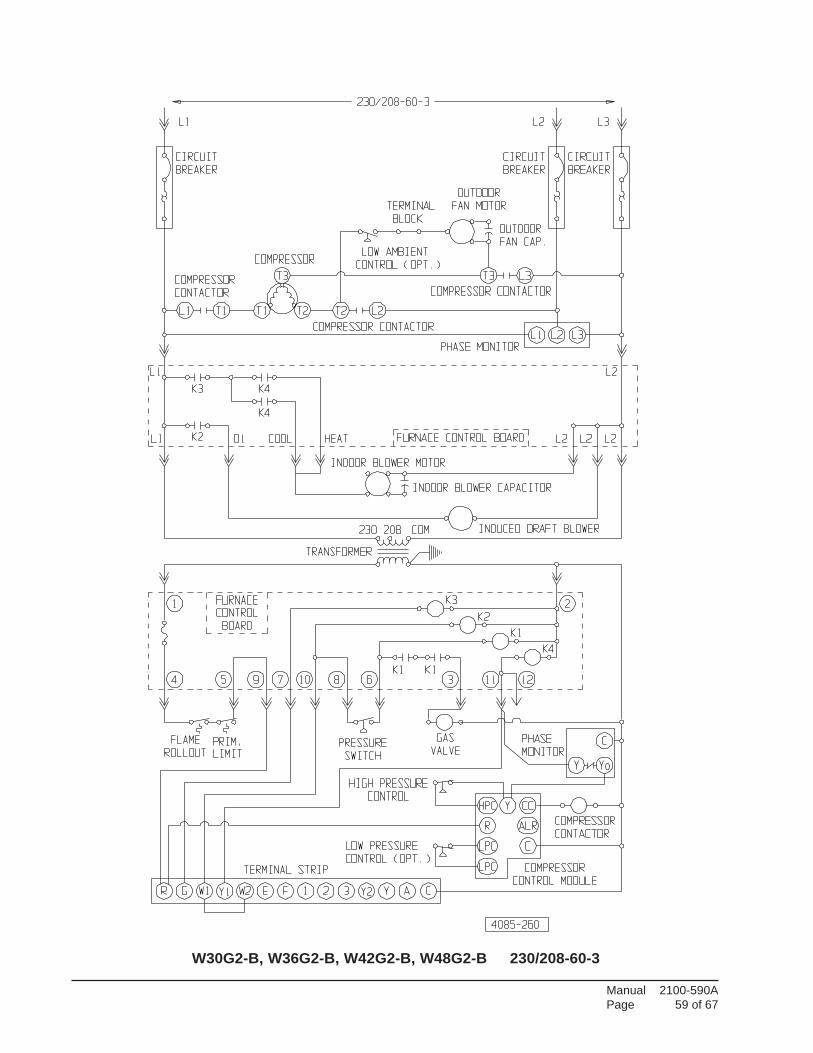
Manual 2100-590APage 59 of 67
W30G2-B, W36G2-B, W42G2-B, W48G2-B 230/208-60-3
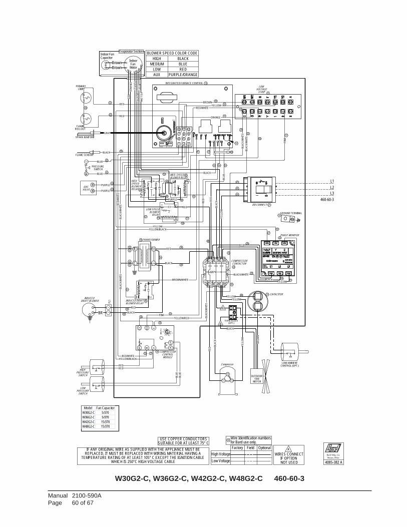
Manual 2100-590APage 60 of 67
W30G2-C, W36G2-C, W42G2-C, W48G2-C 460-60-3
32ORANGE
LPC
CC
HP
C
Y
ALR C
LPC
MIN
UT
ES
4
235
R
1
BLA
CK
/WH
ITE
SPEED 150
135
120
BLACK
BLA
CK
/WH
ITE
FUSE
BLA
CK
BLACK
BLACK/WHITE
BLA
CK
BLACK
P3
BROWN
GRAY
BR
OW
N
BLA
CK
/WH
ITE
BLACK
(OPT.)
460-60-3
BLA
CK
/WH
ITE
BLA
CK
/WH
ITE
USE COPPER CONDUCTORSSUITABLE FOR AT LEAST 75° C
TERM. BLOCK
BLACK
PINK
PIN
K
BLUE
BLUE
1 2 3
4 5 6
8 97
1210 11
BLU
E
L2
BLU
E
L3
A
A
BLU
E
BLA
CK
YE
LLOW
PU
RP
LE
BLU
E
PURPLE
PURPLE
PURPLE
MV
NOC
MV
YELLOW
YELLOW
YE
LLO
W
YELLOW
YELLOW/BLACK
YELLOW/RED
YELLOW
YELLOW
YE
LLO
W
YELLOW/BLACK
Brown
Brown
BROWN/WHITE
RED
RE
D
RED/WHITE
RED
RE
D/W
HIT
E
COM
for Bard use only.Wire Identification numbers
99
RED32
RED/WHITE
32
RED
55
40BLACK
RED
R
C
460V
DRAFT BLOWER
322
PL1
1
BR
INDUCED
MotorFan
Capacitor
Evaporator SectionIndoor Fan
CONTACTOR
40
TRANSFORMER
COMPRESSOR
Indoor
35
GROUND TERMINAL
L1 L2
T1 T2
L3
T3
PHASE MONITOR
15
RED
28
RED29
3031
41
42
43
RE
D
38
39
32
2
31
5
46
RED
27
RE
D
50
BLOWER RELAYMED. SPEED
RELAY BLOWER
BLOWER RELAYINDUCED DRAFT
LOW SPEED
RELAYBLOWERSPEED HIGH
28
53 54 55
58
52
53
MODULE
HIGH
Compressor
CONTROL
SWITCH
MOTOR
COMPRESSOR
PRESSURE
23
REPLACED, IT MUST BE REPLACED WITH WIRING MATERIAL HAVING A TEMPERATURE RATING OF AT LEAST 105° C EXCEPT THE IGNITION CABLE
WHICH IS 250°C HIGH VOLTAGE CABLE
OUTDOOR FAN
INTEGRATED FURNACE CONTROL 13
STRIP 11
LOW VOLTAGE
DISCONNECT
CAPACITOR
21
LOWPRESSURE
SWITCH
IF ANY ORIGINAL WIRE AS SUPPLIED WITH THE APPLIANCE MUST BE
16
WIRES CONNECTIF OPTION NOT USED
L1
OR
AN
GE
54
56
GAS VALVE
32 27
37
35
32
32
32
32
59
PRIMARY
ROLLOUT
SPARK IGNITOR
LIMIT
32
FLAME
FLAME SENSOR
36
PRESSURE SWITCH
T3T1
T2
Bard Mfg. Co.
Bryan, Ohio
4085-382 ALow Voltage
High Voltage
OptionalFieldFactory
32
LOW AMBIENTCONTROL (OPT.)
44
A
34
20
18
32
32
32
35
37
2
3
35
1
2
31
2
35
3
4
48
1
57
57
48
57
48
49
45
45
47
57
45
46
25
RE
D
BLOWER SPEED COLOR CODE
HIGH BLACK
MEDIUM BLUE
LOW RED
AUX PURPLE/ORANGE
Model Fan Capacitor
W30G2-C 5/370
W36G2-C 5/370
W42G2-C 15/370
W48G2-C 15/370
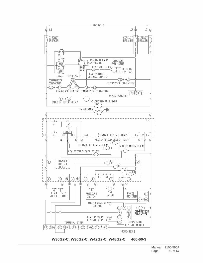
Manual 2100-590APage 61 of 67
W30G2-C, W36G2-C, W42G2-C, W48G2-C 460-60-3

Manual 2100-590APage 62 of 67
W60G2-A 230/208-60-1
LPC
CC
HP
C
Y
ALR C
LPC
MIN
UT
ES
4
235
R
1
32ORANGE
BLACK39
38
42
43RED
38
39
BLA
CK
/WH
ITE
BLA
CK
SPEED 150
135
BLA
CK
208/230-60-1
120
BLA
CK
/WH
ITE
BLA
CK
/WH
ITE
BLACK
FUSE
BLA
CK
BLACK
P3
BROWN
GRAY
BR
OW
N
BLA
CK
/WH
ITE
BLACK
(OPT.)
USE COPPER CONDUCTORSSUITABLE FOR AT LEAST 75° C
TERM. BLOCK
BLA
CK
PINK
PINK
L1
BLU
E
BLUE
BLUE
1 2 3
4 5 6
8 97
1210 11
BLU
E
BLU
E
L2
A
BLU
E
A
PURPLE
PURPLE
C
MV
NO
MV
YE
LLO
W/R
ED
YELLOW
YELLOW
YE
LLO
W
YELLOW
YELLOW
YE
LLOW
Brown
Brown
T1
32
RED
RE
D
RE
D
RED/WHITE
RED
L2
RE
D/W
HIT
E
L1
Wire Identification numbersfor Bard use only.
99
RED32
RED/WHITE
32
RED
35
RE
D
T2
BLACK40
RED
R
C
240V
208V
DRAFT BLOWER
2PL
11
BR
COM
INDUCED
RE
D
Indoor
Capacitor
Fan Motor
Indoor Fan
CONTACTOR
RED
Evaporator Section
40
COMPRESSOR
TRANSFORMER
GROUND TERMINAL 15MOVE RED WIRE TO 208V TAP FOR 208V
OPERATION
35
RE
D
C
MODULE
HE
RM
FAN
HIGH
Compressor
CONTROL
SWITCH
MOTOR
COMPRESSOR
PRESSURE
23
REPLACED, IT MUST BE REPLACED WITH WIRING MATERIAL HAVING A TEMPERATURE RATING OF AT LEAST 105° C EXCEPT THE IGNITION CABLE
WHICH IS 250°C HIGH VOLTAGE CABLE
OUTDOOR FAN
INTEGRATED FURNACE CONTROL 13
VOLTAGESTRIP 11
LOW
CIRCUITBREAKER
CAPACITOR
21
LOWPRESSURE
SWITCH
IF ANY ORIGINAL WIRE AS SUPPLIED WITH THE APPLIANCE MUST BE
16
WIRES CONNECTIF OPTION NOT USED
37
35
GAS VALVE
32 32
37
35
32
32
32
32
59
PRIMARY
ROLLOUT
SPARK IGNITOR
LIMIT
32
FLAME
FLAME SENSOR
36
PRESSURE SWITCH
SR
C
Bard Mfg. Co.
Bryan, Ohio
4085-163 A Low Voltage
High Voltage
OptionalFieldFactory
32
LOW AMBIENTCONTROL (OPT.)
44
A
34
20
18
32
32
32
35
BLOWER SPEED COLOR CODE
HIGH BLACK
MEDIUM BLUE
LOW RED
Model C. Breaker Capacitor
W60G2-A 60A 80+10/440
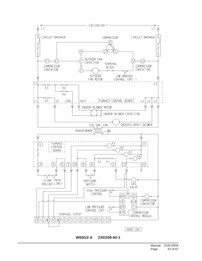
Manual 2100-590APage 63 of 67
W60G2-A 230/208-60-1

Manual 2100-590APage 64 of 67
W60G2-B 230/208-60-3
LPC
CC
HP
C
Y
ALR C
LPC
MIN
UT
ES
4
235
R
1
32ORANGE
MODULE
HIGH
Compressor
CONTROL
SWITCH
MOTOR
COMPRESSOR
PRESSURE
23
REPLACED, IT MUST BE REPLACED WITH WIRING MATERIAL HAVING A TEMPERATURE RATING OF AT LEAST 105° C EXCEPT THE IGNITION CABLE
WHICH IS 250°C HIGH VOLTAGE CABLE
OUTDOOR FAN
INTEGRATED FURNACE CONTROL 13
VOLTAGESTRIP 11
LOW
CIRCUITBREAKER
CAPACITOR
21
LOWPRESSURE
SWITCH
IF ANY ORIGINAL WIRE AS SUPPLIED WITH THE APPLIANCE MUST BE
16
WIRES CONNECTIF OPTION NOT USED
35
GAS VALVE
32 27
37
35
32
32
32
32
59
PRIMARY
ROLLOUT
SPARK IGNITOR
LIMIT
32
FLAME
FLAME SENSOR
36
PRESSURE SWITCH
T3T1
T2
Bard Mfg. Co.
35
Bryan, Ohio
Low Voltage
High Voltage
OptionalFieldFactory
32
LOW AMBIENTCONTROL (OPT.)
44
A
34
20
18
32
32
32
35
37
BLOWER SPEED COLOR CODE
HIGH BLACK
MEDIUM BLUE
LOW RED
4085-261 A
BLACK
SPEED 150
135
120
BLA
CK
BLA
CK
/WH
ITE
FUSE
BLACK
BLACK/WHITE
BLACK
BLA
CK
BLACK
P3
BROWN
GRAY
BR
OW
N
BLA
CK
/WH
ITE
BLACK
(OPT.)
208/230-60-3
BLA
CK
BLA
CK
/WH
ITE
BLA
CK
/WH
ITE
USE COPPER CONDUCTORSSUITABLE FOR AT LEAST 75° C
TERM. BLOCK
BLA
CK
PINK
PINK
L1
BLUE
BLUE
1 2 3
4 5 6
8 97
1210 11
BLU
E
BLU
E
L3
L2
A
BLU
E
A
BLU
E
PURPLE
PURPLE
MV
NOC
MV
YELLOW
YELLOW
YE
LLO
WY
ELL
OW
YELLOW/BLACK
YELLOW/RED
YELLOW
YE
LLOW
YELLOW
YE
LLO
W
YELLOW/BLACK
Brown
Brown
RED
RE
D
RE
D
RED/WHITE
RED
RE
D/W
HIT
E
for Bard use only.Wire Identification numbers
99
RED32
RED/WHITE
32
RED
32
40BLACK
RED
R
C
240V
208V
COM
DRAFT BLOWER
2PL
11
BR
RE
D
INDUCED
Fan MotorIndoor
Capacitor
Evaporator SectionIndoor Fan
CONTACTOR
TRANSFORMER
COMPRESSOR
40
OPERATION208V TAP FOR 208V
MOVE RED WIRE TO
35
RE
D
GROUND TERMINAL
L1 L2
T1 T2
L3
T3
15
PHASE MONITOR 25
RED
28
RED29
3031
41
42
43
RE
D
38
39
32
27
38
39
RE
D
Model C. Breaker Fan Capacitor
W60G2-B 40A 10/370
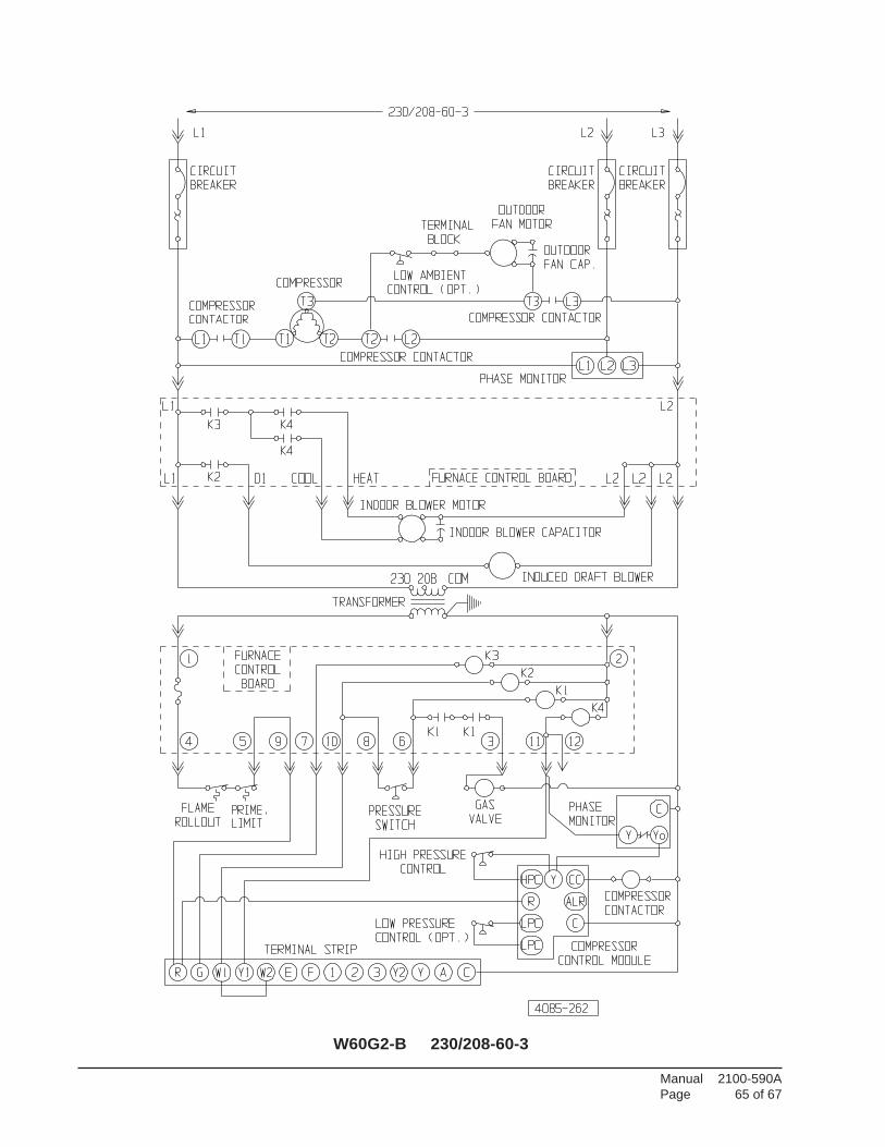
Manual 2100-590APage 65 of 67
W60G2-B 230/208-60-3
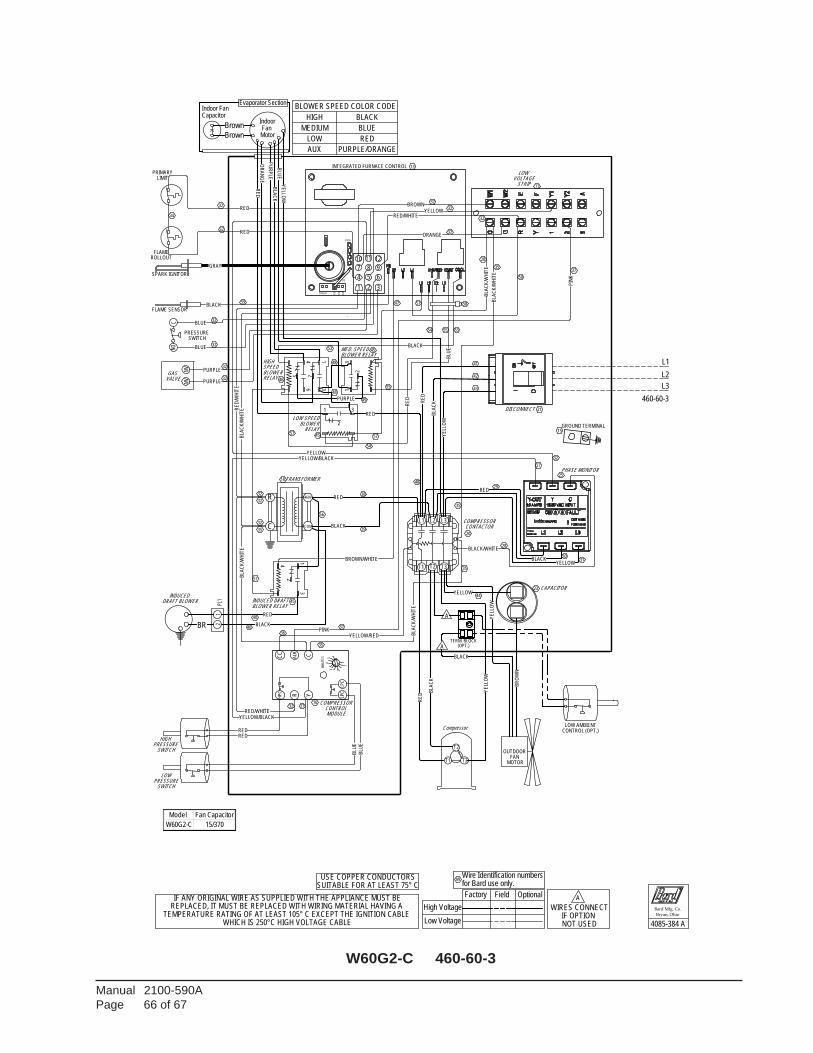
Manual 2100-590APage 66 of 67
W60G2-C 460-60-3
LPC
CC
HP
C
Y
ALR C
LPC
MIN
UT
ES
4
235
R
1
32ORANGE
BLA
CK
/WH
ITE
SPEED 150
135
120
BLACK
BLA
CK
/WH
ITE
FUSE
BLA
CK
BLACK
BLACK/WHITE
BLA
CK
BLACK
P3
BROWN
GRAY
BR
OW
N
BLA
CK
/WH
ITE
BLACK
(OPT.)
460-60-3
BLA
CK
/WH
ITE
BLA
CK
/WH
ITE
USE COPPER CONDUCTORSSUITABLE FOR AT LEAST 75° C
TERM. BLOCK
BLACK
PINK
PIN
K
BLUE
BLUE
1 2 3
4 5 6
8 97
1210 11
BLU
E
L2
BLU
E
L3
A
A
BLU
E
BLA
CK
YE
LLOW
PU
RP
LE
BLU
E
PURPLE
PURPLE
PURPLE
MV
NOC
MV
YELLOW
YELLOW
YE
LLO
WY
ELL
OW
YELLOW/BLACK
YELLOW/RED
YELLOW
YELLOW
YE
LLO
W
YELLOW/BLACK
Brown
Brown
BROWN/WHITE
RED/WHITE
RED
RE
D
RED
RE
D/W
HIT
E 55
for Bard use only.Wire Identification numbers
99
RED32
RED/WHITE
32
RED
32
40BLACK
RED
R
C
460V
COM
DRAFT BLOWER
2PL
11
BR
INDUCED
MotorFan
Capacitor
Evaporator SectionIndoor Fan
CONTACTOR
40
TRANSFORMER
COMPRESSOR
Indoor
35
GROUND TERMINAL
L1 L2
T1 T2
L3
T3
PHASE MONITOR
15
RED
28
RED29
3031
41
42
43
RE
D
38
39
32
2
31
5
46
RED
27
RE
D
50
BLOWER RELAYMED. SPEED
RELAY BLOWER
BLOWER RELAYINDUCED DRAFT
LOW SPEED
28
RELAYBLOWERSPEED HIGH
58
55 5354
53
COMPRESSOR
HIGH
Compressor
CONTROL
SWITCH
MOTOR
MODULE
PRESSURE
23
REPLACED, IT MUST BE REPLACED WITH WIRING MATERIAL HAVING A TEMPERATURE RATING OF AT LEAST 105° C EXCEPT THE IGNITION CABLE
WHICH IS 250°C HIGH VOLTAGE CABLE
OUTDOOR FAN
INTEGRATED FURNACE CONTROL 13
STRIP 11
LOW VOLTAGE
DISCONNECT
CAPACITOR
21
LOWPRESSURE
SWITCH
IF ANY ORIGINAL WIRE AS SUPPLIED WITH THE APPLIANCE MUST BE
16
WIRES CONNECTIF OPTION NOT USED
L1
OR
AN
GE
54
56
GAS VALVE
32 27
37
35
32
32
32
32
59
PRIMARY
ROLLOUT
SPARK IGNITOR
LIMIT
32
FLAME
FLAME SENSOR
36
PRESSURE SWITCH
T3T1
T2
Bard Mfg. Co.
Bryan, Ohio
4085-384 ALow Voltage
High Voltage
OptionalFieldFactory
32
LOW AMBIENTCONTROL (OPT.)
44
A
34
20
18
32
32
32
35
37
2
335
1
2
31
2
35
3
4
48
1
57
57
48
57
48
49
45
45
47
57
45
46
25
RE
D
BLOWER SPEED COLOR CODE
HIGH BLACK
MEDIUM BLUE
LOW RED
AUX PURPLE/ORANGE
Model Fan Capacitor
W60G2-C 15/370
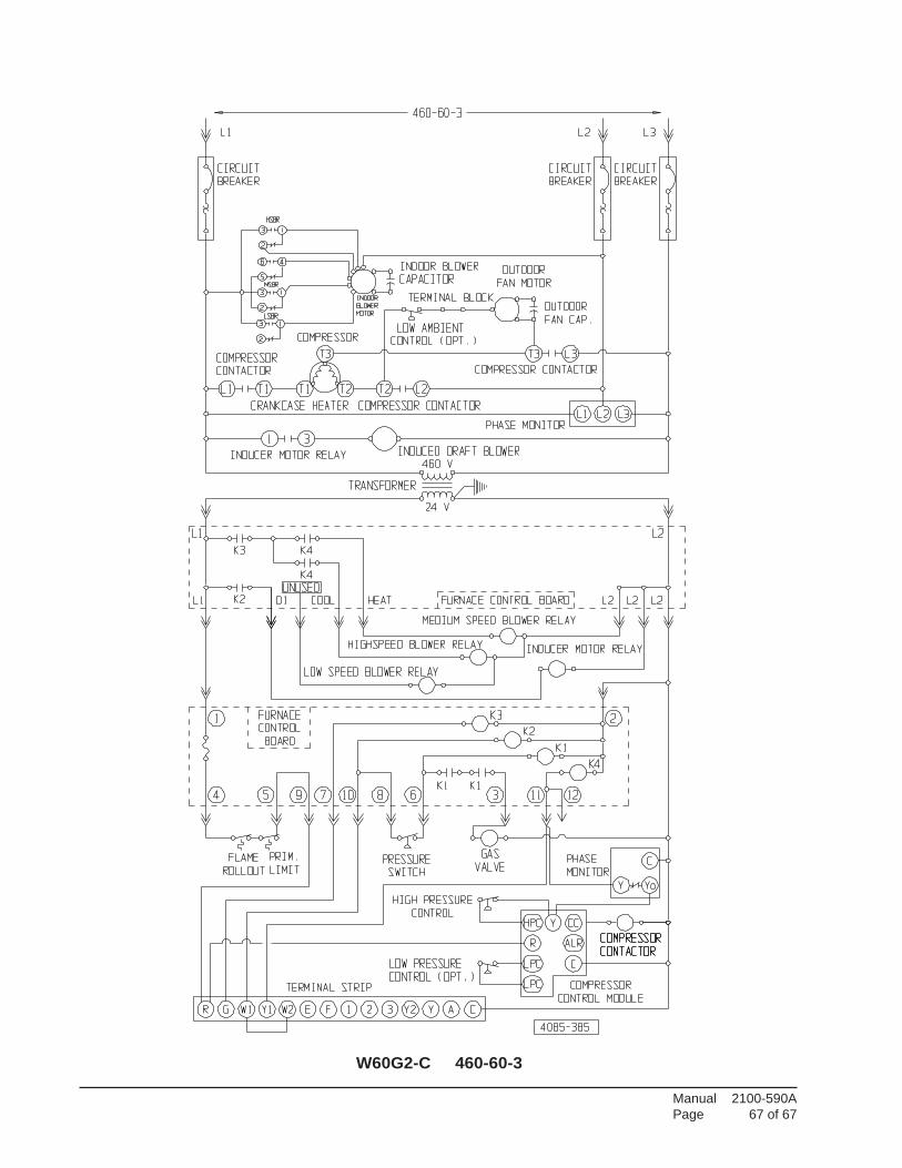
Manual 2100-590APage 67 of 67
W60G2-C 460-60-3