2.1 setting-out facework – stretcher half...
TRANSCRIPT

2 BRICKLAYING TECHNIQUESThis section deals with basicbricklaying skills common to all
brickwork assemblies – settingout and control of the regularity
of the work, the use of tools,forming joints, etc.
2.1 SETTING-OUT FACEWORK – STRETCHER HALF-BOND
Face brickwork should beset-out at the lowestpracticable level, ideallybelow finished ground level,before bricklaying begins,otherwise ill-considereddecisions may have to bemade later regarding bondingand cutting, particularly atwindow and door openings.The result may be a lastingmonument of poorworkmanship.
Setting-out facework isnormally the responsibilityof the supervising bricklayerwho will, after consultingthe architect, determine thedetailed bond pattern andthe location of any broken orreverse bond.
Setting-out the brickwork isdifferent from setting-out thebuilding which is done beforeexcavation begins.
OBJECTIVESOne of the main purposes ofsetting-out facework is to createa matching and balancedappearance of brickworkparticularly at the reveals oneither side of door and windowopenings and ends of walls.
An understanding of therelationship between openingsand the bond pattern, if sharedby bricklayers, site supervisorsand architects will minimisedisappointments and delays.
BRICK DIMENSIONSBrickwork should be setout using the co-ordinatingsize of the length of a brick,e.g. 225 mm (215 mm worksize � 10 mm nominal jointfor bricks to BS EN 771-1)(1)
(fig 2.1).The above co-ordinating
and work sizes are those ofthe bricks most widely usedin the UK, but the specificationmay call for the use of bricksof other sizes. In this case,
WORK SIZE(co-ordinating size lessnominal 10 mm joint)
ACTUAL SIZE(as measured)
225 112.5
This is a general rule which isto be applied to faceworkcontaining window and dooropenings. It is not necessaryto apply it rigidly in allcircumstances, e.g. a free-standing wall for whichthe bricks have all beendelivered at one time.
Although the basic principles of setting-outapply to all brickwork, of whatever bond,this section deals specifically with stretcherhalf-bond only.
CO-ORDINATINGSIZE
Used for design andsetting-out
215
e.g. 213
e.g. 217
e.g. 100.5
e.g. 104.5
102.5
Figure 2.1.
H6469-Ch02 9/15/05 1:08 PM Page 12

SETTING-OUT FACEWORK – STRETCHER HALF-BOND 13
setting-out should be done toa corresponding system ofdimensions, e.g. if the work sizeof a brick is 190 � 90 � 65 mma nominal 10 mm is allowedfor mortar joints giving a co-ordinating size of200 � 100 � 75 mm.
• If brickwork is set-outusing the average actualsize of the bricks in thefirst delivery, difficultiesmay occur if subsequentdeliveries differ.
DESIGNBroken bond and possiblywasteful cutting can be avoidedif the overall length of walls andthe widths of doors, windowopenings and brickworkbetween the openings are allmultiples of a brick stretcher.The bonding either side ofreveals will also matchsymmetrically at each course(fig 2.2). (This applies to stretcherhalf-bond and English bond butnot to others such as Flemishand Dutch bond.)
In practice, this ideal situationseldom occurs and a satisfactorysolution is dependent onbricklaying skills.
PERPENDSThe bonding pattern should beset out at ground level so thatthe first few courses establishperpends for the full height ofthe wall and any problems maybe resolved with the architect orsite supervisors.
Pencil tick marks made on thebrick face should be light anddiscreet (fig 2.3). Heavy marksover the full height of the brickcan spoil the finished brickwork.A test should be made on thetype of brick to be used beforebricklaying begins as pencil marksare more conspicuous and moredifficult to remove on some typesof bricks than others.
The verticality of perpends infacing brickwork is as visuallyimportant as the horizontality ofcourses. In practice satisfactoryverticality is achieved byplumbing about every fourth orfifth perpend.
REVEALSThe positions of all windowopenings and ‘reveal’ bricksshould be identified when settingout the first few courses (fig 2.4).This ensures that perpends cancontinue unbroken for the fullheight of the wall.
Broken bondReveal bricks provide fixed pointsbetween which the bonding isset out (fig 2.5). The usuallyshort lengths of brickworkbetween windows offer littlescope for ‘adjusting’ the widths
3Bricks
3Bricks
5Bricks
5Bricks
3Bricks
Figure 2.2. ‘Ideal’ dimensions – whole numbers of bricks and symmetrical reveals.
Figure 2.3. Plumbing perpends.
H6469-Ch02 9/15/05 1:08 PM Page 13

14 BRICKLAYING TECHNIQUES
of cross joints in order to avoidbroken bond.
Broken bond can sometimesbe avoided by ‘tightening’ or‘opening’ the joints. In doing sobricklayers should work to thestandard co-ordinating size of225 mm (i.e. 215 � 10 mm) ratherthan the actual size of the bricks(see ‘Brick Dimensions’ above).
Reverse bondInstead of slightly and evenlyadjusting cross joints to avoidbroken bond it may be decided,with the agreement of thearchitect, to use reverse bond.This allows bricks in reveals eitherside of openings or at each endof a wall to be asymmetrical. Bydoing so it ignores the mainprinciple of setting out face
work, which is to create abalanced appearance, butsometimes architects preferreverse bond to broken bond.
Broken bond occurs below awindow opening, as the result ofsetting-out to achieve symmetryof reveal bricks (fig 2.6a).
Window ‘reveal’ brickslocated at ground levelbefore bricklaying begins
Door opening locatedfrom drawings
Figure 2.5. Setting-out openings atground level.
Figure 2.6a. Broken bond.
Opening4½ bricks
Position ofwindow opening
to be built
Plumbedperpendsdpc
‘reveal’
‘reveal’ brickspositioned atground level
Figure 2.4. Setting-out window positionat ground level.
H6469-Ch02 9/15/05 1:08 PM Page 14

SETTING-OUT FACEWORK – STRETCHER HALF-BOND 15
Broken bond can be avoidedby using reverse bond (fig 2.6b).It is, however, unlikely to beacceptable if contrastingcoloured reveal bricks areused as a decorative feature.Alternative solutions are shownin (fig 2.8).
Bricks should be spaced ‘dry’from each end of a wall whichhas no openings, to enable anagreed bonding to be reached(fig 2.7).
Figure 2.7. A wall without openings –bricks spaced out ‘dry’.
Opening4½ bricks
Figure 2.6b. Reverse bond.
Figure 2.8d. Reversing the bond at each end of a wall may also be considered preferableto broken bond.
Figure 2.8c. However, some architects may prefer three-quarter bricks at each end.
Figure 2.8b. In this situation a bricklayer will usually use broken bond, located centrally.
Figure 2.8a. The ideal solution is seldom possible.
ALTERNATIVE SOLUTIONS
H6469-Ch02 9/15/05 1:08 PM Page 15

16 BRICKLAYING TECHNIQUES
POLYCHROMATIC BRICKWORKWhere different coloured bricks areused, especially in band courses,check for differences in averagework sizes between them to avoidexcessively wide, narrow or badlyaligned cross joints. Such problemscan usually be avoided by setting-out to 225 mm increments ratherthan attempting to maintain10 mm wide cross joints.
Reference(1) BS EN 771-1:2003 Table NA.1
‘Coordinating and work sizes ofclay brick’.
KEY POINTS
■ Locate the position ofopenings and the associatedreveal bricks above whensetting out at ground leveland before commencingbricklaying.
■ Base setting-out at groundlevel on the 225 mmco-ordinating dimension NOT theactual sizes of the bricks in thefirst delivery.
■ Run out facing bricks ‘drybonded’ between the revealsand quoins.
■ Plumb the perpends of brokenbond from ground level upwards.
■ ‘Tighten’ or ‘open’ cross jointsslightly and evenly in order toavoid broken bond wherepossible.
■ Generally centralise broken bondin walling and below windowsunless the use of three-quarterbricks at each end is preferredby the architect.
■ Reverse bond may be preferredby some architects in order toavoid broken bond.
2.2 GAUGE AND STOREY RODS
Bricklayers, as part of aconstruction team, have toco-ordinate or ‘work in’ withother building components,particularly doors andwindows.
One of the most importantco-ordinating processes isknown as ‘keeping the gauge’.
KEEPING TO GAUGEThis refers to working betweentwo given points, A and B, andkeeping the bed joints of eventhickness (fig 2.9).
STANDARD GAUGE• The standard gauge is four
courses to 300 mm (i.e. 4 �75 mm, the brick co-ordinating size) (fig 2.10).
• These standard bricks aremade to a work size of65 mm high (the intendedor target size) which is equalto the co-ordinating size of
B
A
65
65
65
65
75
10
10
10
10
75
4 courses= 300 mm
75
75
Figure 2.9.Gauge and even jointthickness.
Figure 2.10. Standard gauge.
H6469-Ch02 9/15/05 1:08 PM Page 16

GAUGE AND STOREY RODS 17
75 mm less a 10 mmnominal joint (fig 2.10).
• The actual size will be a littlemore or less than the worksize but the standard gaugemust be maintained even
though the joints will be alittle less or more than thenominal 10 mm. A goodbricklayer will ensure that allbed joints are regularin appearance (fig 2.11).
• Standard gauge andregular bed joints takeprecedence over 10 mmjoints.
The specification may call forthe use of bricks of a size otherthan that given in BS EN 771-1(1).For example thinner bricks,sometimes referred to as Tudorbricks, may be 41 mm high andwould be specified to be laid toa gauge of 6 courses to 300 mm,i.e. with a nominal bed joint of9 mm.
GAUGE RODSGauge rods are made and usedto maintain gauge and regularbed joints. They are made from atimber lath (typically 50 � 25 mmnominal). The length dependson the height of componentssuch as doors and windows.
The standard gauge is markedon one side and one edge.
Making a gauge rodAccuracy is essential and isachieved by using runningdimensions (fig 2.12a).
• Extend a tape from one endof the lath.
• Make pencil marks every300 mm (300, 600, 900, etc.as running dimensions).
• Sub-divide these incrementsinto 75 mm increments(75, 150 and 225 mm).
• Use a square to ‘square off’the pencil marks at rightangles to the sides of the lath(fig 2.12b).
• With a saw make permanentgauge cuts. NOTE: an oldwoodworking squareprovides a good guidingedge for the saw.
4 co
urse
s to
300
mm
Work size is 65 mmand nominal joint is10 mm
When average actualsize is more than worksize, then thinner butregular joints
When average actualsize is less than worksize, then thicker butregular joints
Figure 2.11. Building to standard gauge – maintaining regular bed joints.
Figure 2.12b. Permanent gauge cuts.
300 600 900
Figure 2.12a. Marking ‘running dimensions’.
H6469-Ch02 9/15/05 1:08 PM Page 17
18 BRICKLAYING TECHNIQUES
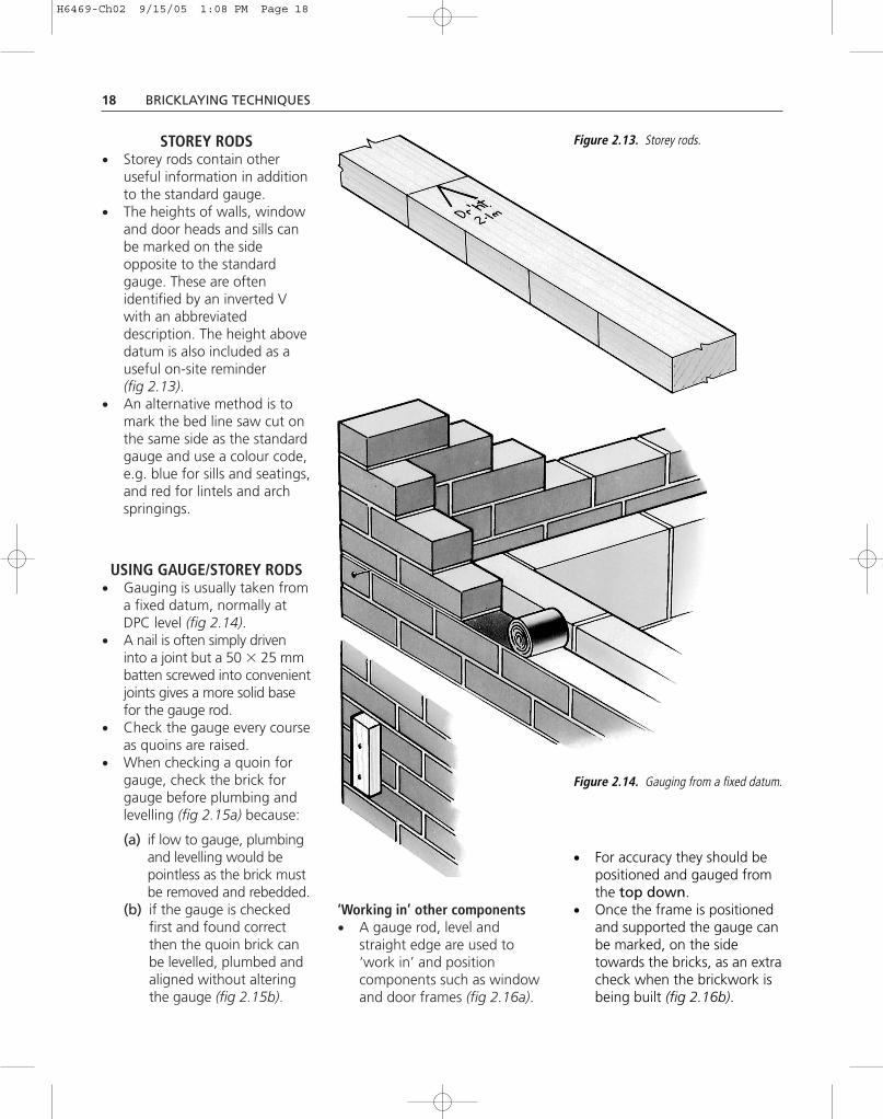
STOREY RODS• Storey rods contain other
useful information in additionto the standard gauge.
• The heights of walls, windowand door heads and sills canbe marked on the sideopposite to the standardgauge. These are oftenidentified by an inverted Vwith an abbreviateddescription. The height abovedatum is also included as auseful on-site reminder(fig 2.13).
• An alternative method is tomark the bed line saw cut onthe same side as the standardgauge and use a colour code,e.g. blue for sills and seatings,and red for lintels and archspringings.
USING GAUGE/STOREY RODS• Gauging is usually taken from
a fixed datum, normally atDPC level (fig 2.14).
• A nail is often simply driveninto a joint but a 50 � 25 mmbatten screwed into convenientjoints gives a more solid basefor the gauge rod.
• Check the gauge every courseas quoins are raised.
• When checking a quoin forgauge, check the brick forgauge before plumbing andlevelling (fig 2.15a) because:
(a) if low to gauge, plumbingand levelling would bepointless as the brick mustbe removed and rebedded.
(b) if the gauge is checkedfirst and found correctthen the quoin brick canbe levelled, plumbed andaligned without alteringthe gauge (fig 2.15b).
‘Working in’ other components• A gauge rod, level and
straight edge are used to‘work in’ and positioncomponents such as windowand door frames (fig 2.16a).
Figure 2.13. Storey rods.
• For accuracy they should bepositioned and gauged fromthe top down.
• Once the frame is positionedand supported the gauge canbe marked, on the sidetowards the bricks, as an extracheck when the brickwork isbeing built (fig 2.16b).
Figure 2.14. Gauging from a fixed datum.
H6469-Ch02 9/15/05 1:08 PM Page 18

GAUGE AND STOREY RODS 19
Reference(1) BS EN 771-1:2003 Table NA.1 in
National Annex.
Figure 2.15a. Checking gauge of quoin brick.
Figure 2.16b. Gauge marked on back of door frame.
Figure 2.16a. ‘Working in’ a door frame.
Figure 2.15b. Plumbing quoin brick.
KEY POINTS
■ Use running measurements tomark gauge/storey rod accurately.
■ Use a square to mark gauge linesacross the lath.
■ Set-out the gauge from thetop down on components to bebuilt in.
■ Store gauge rods flat and dry.They are important pieces ofequipment for producing goodquality brickwork and should betreated as such.
H6469-Ch02 9/15/05 1:08 PM Page 19

20 BRICKLAYING TECHNIQUES
Existing buildingsIf the gauge of new work isrequired to match that ofthe existing brickwork, preparea gauge rod from the existingwall.
Work below ground level• Drive a peg into the ground to
indicate DPC level (fig 2.17).• With a level, straight edge
(if necessary) and a gaugerod, gauge down into thefoundation trenches.
• If there is not a wholenumber of 75 mm courses,any thickened bed joints orsplit course must be at thebottom of the brickwork.
• The object is to ensure that abed joint will coincide withDPC level.
These apply both to straightand curved walls, but theprocedures detailed in thissection are based on straightwalls (for curved brickworksee Section 5.7).
Quoins must be raised ascontrol points before lining-incan begin.
BUILDING AN ACCURATECORNER
When the corners of thebrickwork have been marked onthe foundation concrete then:
• Lay out materials within easyreach, without obstructingthe bricklayer.
• Run out the correct bond, dry,before any bricks are laid.
• Ensure that a datum peg,marked with the DPC level,is within reach of the quoinbrick (fig 2.19).
• Lay the quoin brick first.Push it down to gauge and‘level by eye’ (fig 2.20).Select reasonably squareand regular quoin bricks tomake it easier to build anaccurate corner.
Figure 2.17. Gauging downfrom datum.
2.3 LINE, LEVEL AND PLUMB
Whether building with bricksor blocks the same basicprocedures apply.
• The construction of controlpoints.
• Lining-in between thesepoints (fig 2.18).
Corners ascontrol points
Line betweencontrol points
Figure 2.18. Basic procedure.
H6469-Ch02 9/15/05 1:08 PM Page 20

LINE, LEVEL AND PLUMB 21
The trend, in practice, to buildcorners up to eighteencourses high should beavoided as it entails morework to level and line usinga spirit level and, where itleads to toothing (fig 2.23c),to poorly filled weak jointsand a poor appearance.Furthermore, it is quicker to‘run the line’ than to level andrange quoin courses.
Figure 2.19.Levelling quoinfrom datum.
Figure 2.21. Levellingfrom the quoin brick.
Figure 2.20. Laying thequoin brick.
CheckgaugeCheck brick
level by eye
Eye downboth facesin line withwork below
• Level from the quoin brick, asthe first course cannot beplumbed (fig 2.21).
• The number of courses to beraised to complete the cornersis the same as the totalnumber of bricks in the firstcourse at the corner (fig 2.22).
6 bricks in firstcourse at cornergives 6 courseshigh
• Note that the control point forplumb and gauge is the quoinbrick and the more bricks thatare laid out from it the morelikely they are to run out ofline (fig 2.23a). It is thereforegood practice to raise smallcorners, run in the bricksbetween them and then tocontinue raising them by thesame amount (fig 2.23b). Figure 2.22. A practical tip.
Foundation
Quoin brick
Check gaugewith spiritlevel
Datum peg
H6469-Ch02 9/15/05 1:08 PM Page 21

22 BRICKLAYING TECHNIQUES
• The second course can belaid, quoin brick first. Keepa check on vertical gauge bylevelling out from the quoinbrick in both directions atevery course. At this stage,plumbing the corner can beonly approximate as there arenot many bricks to place thelevel against, so restrain thebottom of the level with thefoot and hold the upper part.Always plumb the same partof the corner, otherwise smallirregularities in the bricks maycause inaccuracies. Hold thespirit level plumb and gentlytap the bricks towards oraway from the level, until thefull height of the brick, notjust one corner, is in contactwith the level, and the bubblereads plumb (fig 2.24).Sometimes an irregularbrick will have to be knockedout of level to bring its faceplumb.
Line pushed outof true by poor‘lining-in’ ofcorner
Line of wall Bricklayer´sline
Repeat
Repeat
Raise cornersrun in bricksbetween
Figure 2.23c. Building corners –unsatisfactory method.
Figure 2.23b. Building corners –recommended method.
Figure 2.23a. The danger of long corners.
Hand on top
Foot at bottom
Tapping brick backFigure 2.24. Tapping brick to the level.
H6469-Ch02 9/15/05 1:08 PM Page 22

LINE, LEVEL AND PLUMB 23
Subsequent courses are laid onthe corner, racking back asnecessary, in the followingsequence:
• Bed the quoin brick to gaugeand level ‘by eye’.
• Check it for gauge and levelin both directions.
• Complete each quoin course,levelling from the quoin brickbefore the mortar bedstiffens.
• Plumb both faces of thequoin.
• Check cross joint thicknessand perpends.
• ‘Range in’ both faces usingthe spirit level to check faceplane alignment (fig 2.25).
• Double-check plumbing onboth faces in case they havebeen disturbed.
The student should consciously‘train his eye’ to estimate bed jointthickness, level and plumbaccurately to minimise theadjustment needed upon checkingwith gauge rod and level.
PLUMBING PIERSWhen building piers, avoidspreading excessive beddingmortar as the heavy tappingneeded will disturb the coursesbelow which will have had littletime to stiffen.
With isolated piers it is goodpractice to get a ‘turn of thebubble’ batter on both sides. Thisshould prevent the cross jointgetting larger and the piers from‘hanging out’ towards the top(fig 2.26).
Another method is to plumbonce in each direction and tocheck the opposite face with atape.
USING PROFILESThe use of patent profileseliminates the need for raisingquoins and can give greateraccuracy because they are placeddirectly at the control point andthe line is fixed to them(fig 2.27).
NOTE: Patent profiles of variouseffective designs are produced bydifferent manufacturers. The toolillustrated in diagrams in thisbook is only intended as a typicalexample and no inference shouldbe drawn that this particulardesign is approved or preferredby the authors.
Some other designs haveadditional features and/oraccessory fittings that extendtheir usefulness in assistingaccurate and well controlledbricklaying.
MAINTAINING LEVELThe level of the wall ismaintained by accurate gaugingfrom the same fixed datumwhich is usually DPC level. Thereshould be a datum peg at eachcontrol point or corner and thebricklayers should work downfrom them in substructure andup from them in superstructure
Figure 2.25. Aligning the ‘racking back’.
Figure 2.26. Plumbing piers.
Plumbbothsides
H6469-Ch02 9/15/05 1:08 PM Page 23

24 BRICKLAYING TECHNIQUES
Cramped intoraked verticaljoint
Screws toplumb profile
Special clip cornerblock to locate line
brick wall as soon as possible asdatum pegs often becomedislodged on site.
USING A GAUGE RODIf the storey height of a buildingdoes not work to gauge, orexisting brickwork has to bematched, then a ‘one-off’ gaugeor storey rod should be made upto suit each unique situation ofnon-standard gauge. The use ofsuch a non-standard gauge orstorey rod, where this is
necessary, allows the opening orclosing of a gauge to be gradualand not noticeable. The storeyrod can be marked to showcritical heights such as sill,lintel, joists and plate levels.More information on themaking and use of rods is givenin section 2.2 ‘Gauge andstorey rods’.
If the corners are built asshown in fig 2.29 and the line isfixed to the same course heightthen the wall built between thecorners will be level.
Figure 2.27. A typical patent profile.
Figure 2.28. Gauging down belowdatum.
(fig 2.28). If there is not a wholenumber of 75 mm coursesbetween datum and stripfoundations, any thickened bedjoints or split courses must be atthe bottom of the brickwork. It isadvisable to set a datum on the
H6469-Ch02 9/15/05 1:08 PM Page 24

LINE, LEVEL AND PLUMB 25
LINING IN PROCEDURESThe lineIt is essential to use a goodquality line, either of cotton,hemp or nylon. Preferences are amatter for the individual, but foraccuracy the line should be light,to prevent sag, and durable so asnot to rot if left damp, andwithout knots.
If lines cannot be spliced, theknot should be wound onto thepin. When the remaining lengthbecomes too short the whole lineshould be replaced.
The corner blockTo avoid ‘pin-holes’ in a quointhe line can be held to the cornerwith blocks which are usuallymade from wood (fig 2.30). Theline is pulled through the saw cutand taken once under the line,and through the saw cut again.Hitch the line round the pin toprevent its hanging down too far(fig 2.31).
Place the corner blocklengthways to the direction tobe run. Keep the line taut toprevent the block from falling.Pull the line through the block asbefore. The amount of tensionnecessary to keep the line tautand with no visible sag whensighted, will depend on thelength of the wall betweencorners (fig 2.32).
Both corners builtto same heightand gauge
Datum pegs atsame level
Figure 2.29. Two corners ready for ‘running in’.
Pass line through sawcut,round block, downbetween block and mainstretch, round block andthrough sawcut again
Saw cut
NOTE: the actual sizeis to suit individualpreferences
approx. 80 m
m
approx.40 mm
Figure 2.30. A typical cornerblock.
Figure 2.31. Using corner blocks.
H6469-Ch02 9/15/05 1:08 PM Page 25

26 BRICKLAYING TECHNIQUES
A corner block on the top courseIf the mortar is not completelyset the top brick may becomedislodged when the corner lineis raised to the last course,
especially on long walls. This canbe avoided by weighting the topbrick with a few others placeddry (fig 2.33).
Checking the general alignmentof cornersThe bricklayers should check thatthe quoin courses ‘follow theline’ each time it is raised.
Running-in to the lineBricklayers should positionthemselves so that they can sightboth down and across the line(fig 2.34). When eyeing downthey should be able ‘to just seethe light’ between the brick andthe line. Some bricklayers thinkof the gap as the thickness of atrowel. The arris should nevertouch the line. The bottom arrisshould align with the wall facebelow. When eyeing across theline the top of the brick shouldnot project above the line.
NOTE: it is usually the ‘righthand bricklayer’ on a wall whotensions a line.
If the line is stretched over along length and sags due to itsself-weight, a tingle plate shouldbe used to support the line asdescribed in section 2.4 ‘Verticalperpends’ and section 5.1‘Copings and Cappings’.
Irregular shaped bricksLaying some handmade andstock bricks requires experienceand skill above that required tolay more regularly shaped bricks.Surface irregularities must notinterfere with the line.
Internal cornersHere the quoin brick is not theonly major plumbing point. Theadjacent brick is also importantbecause the line is often fixed100 mm or more from theinternal angle (fig 2.35).
Figure 2.32.
Line ontop course Bricks placed
‘dry’ to stabilisetop brick
Figure 2.33. A cornerblock on the top course.
Brick NOTtouching line
Brick NOTabove line
Figure 2.34.
H6469-Ch02 9/15/05 1:08 PM Page 26

LINE, LEVEL AND PLUMB 27
A slightly larger corner willneed to be raised because theline will need a few bricks ascounterweights to preventdislodgement especially on longwalls. On the top course, the lineshould be taken over the back ofthe wall and the line held in
position by a brick placed dry onthe corner (fig 2.36).
Maintaining piers in alignmentPiers in a line should never bebuilt separately. The corner orfirst piers at each end shouldbe raised ahead of the
remainder and a line strungbetween. The piers shouldalways be a course or sobehind the main wall so thata tight line can be pulledthrough the face of theinfilling panels of brickwork(fig 2.37).
Corner blocksand line toalign piers
Line and pins toalign main wall
Figure 2.37. Maintainingpiers in alignment.
KEY POINTS
■ Always set out brickwork fromprofiles or grid lines. Do not justfollow the centre of the trench orassume that steel or concretecolumns are correctly positioned.
■ Run out a wall in dry bricks tolocate openings, broken bondand perpend plumbing pointsbefore you start laying bricks.
■ Always work from datums tokeep gauge of brickwork correctall round the building.
■ Keep to standard gauge for newwork.
■ Always make a storey rod inpreference to checking with a tapeto keep vertical gauge constant.
■ Raise small quoins throughout aworking day.
■ Always rack back when raising aquoin. Avoid toothing.
■ Keep your foot on the bottom ofthe spirit level when plumbing aquoin.
■ Always keep a tight line.■ Make broken bond as
inconspicuous as possible(i.e. two equal cuts over onecut in alternate courses ispreferable to a single cutin every course in stretcherbond).
■ Plumb perpends every fourth orfifth brick along a course.
■ Always plumb the perpends ofbroken bond.
Face side
Figure 2.36. Top courseof internal corner.
Face side
Pins intocross joints
Figure 2.35. Pins atinternal corners.
H6469-Ch02 9/15/05 1:08 PM Page 27

28 BRICKLAYING TECHNIQUES
MAINTAINING PERPENDSWHEN RUNNING THE LINE
Once the corners have been builtthe bricklayers ‘run the line’, thatis they build the walling betweenthe corners. By positioning everyfourth or fifth brick exactly abovethe corresponding bricks in lowercourses the ‘perps’ will remainconstant in position.
If the ‘perps’ are notconsciously aligned they maygradually close up on one part ofthe walling whilst opening on thenext part especially if onebricklayer is quicker than the rest.This might result in one bricklayerhaving to ‘crop’ or cut bricks to
2.4 VERTICAL PERPENDS
LinePlumb-uptingle brick
Brick batlocatestingle
Tingle plate
Bricklayer’s line
Figure 2.38. Use of a tingle brick to prevent ‘travelling’ perps.
achieve a fit in his part of thewall whilst another may have toincrease the thickness of his‘perps’ to compensate for theresulting discrepancies.
The methodThe difficulties, as described, caneasily be overcome with care andforethought.
Firstly, divide the length of thewall into equal sections (normallytwo) by the use of a tingle, adevice for taking up the slack ordrop inherent in a line pulledbetween two distant points. Thetingle and its use is illustratedand described in section 5.1‘Copings and Cappings’.
The tingle is placed on a brickbedded near the centre of the runof walling. Plumbing this tinglebrick up the wall effectively dividesthe wall into two sections, causingthe bricklayers to adjust only theperpends within their ownsections. This will help to preventthe perpends from ‘travelling’across the facework (fig 2.38).
Finally, check, at frequentintervals horizontally, that theperpends are vertically abovethose in the courses below.
In good quality facework thevisible vertical joints inalternate courses should havethe general appearance ofrising vertically one abovethe other for the full height ofthe building without‘wandering’. Although thismay appear to be a simplematter, it can be achievedonly if supervisors andbricklayers think ahead andexercise care and attention.
DEFINITIONThe visible lines of vertical orperpendicular cross jointsbetween bricks are commonlycalled ‘perpends’ or ‘perps’.
H6469-Ch02 9/15/05 1:08 PM Page 28

VERTICAL PERPENDS 29
BELOW GROUND LEVELWhenever possible, the actionsnecessary to maintain verticalperpends should be consideredwhile construction is belowground level and beforefacework begins. Door andwindow jambs should beaccurately located and the‘reveal’ bricks plumbed upwardsso that the perpends may bemaintained vertically and will notbe required to ‘travel’ across thefacework to the correct positionfor the reveals of a window at ahigher level. This matter is morefully covered in section 2.1‘Setting-out facework’.
Once openings and perpendshave been identified and located,broken bonds may appearelsewhere. If full length bricks orthe intended bondingarrangement cannot bemaintained over the length ofthe wall then somerearrangement will be required.This may result in a new patternof cut bricks.
PARTICULAR CARE WITHBROKEN BOND
Great care must be taken inaligning the perpends of anypattern of broken bond that hasbeen formed or any otherchanges in the facework bonding(fig 2.39a). These changes attractthe eye and if they contain anymisalignment of perpends it willbe more noticeable than in thegeneral mass of brickwork suchas a flank wall (fig 2.39b).
If the discrepancy in the wall isonly slight then it may be betterto tighten or open carefully allcross joints rather than to ‘crop’bricks. If the perpends are to bealigned correctly then all cut
bricks should be exactly the samelength and the easiest way to dothis is to prepare the bricksbeforehand using a brick gaugeand if available a masonry benchsaw.
CHECKING PERPENDALIGNMENT
Once above DPC, the bricklayerneeds to plumb up and mark the
arris of every fourth or fifthbrick very lightly in pencil.Make a test with the type ofbrick in use to ensure that themarks can either be removed orwill not be visible on the finishedbrickwork. Particular care mayhave to be taken with sometextured bricks.
Checking perpends can easilybe carried out by either of thefollowing methods:
Plumb perpends
Figure 2.39a. Care taken to plumb a broken bond.
Figure 2.39b. Poor plumbing at broken bond is visually disturbing.
Plumb line
Perpends allowedto creep
H6469-Ch02 9/15/05 1:08 PM Page 29

30 BRICKLAYING TECHNIQUES
• Place the spirit level on thearris of the lower alternatecourses and transfer theirpositions up the wall(fig 2.40).
• Place a large ‘T’ squareagainst the arris of the loweralternate courses and transfertheir positions up the wall.
Perpends should be checkedconstantly, starting with thecorners. If the perpends on alarge corner are ‘allowed towander’ it may be impossible tocorrect the error in the main wallabove (fig 2.41). Racking backrequires special care becauseperpend misalignment can veryquickly occur. Also perpendmisalignment can easily occurwhen toothing is used (fig 2.42).
Toothing should be avoided asit usually results in poorly filledjoints when filling in thetoothing. This is likely to increasethe amount of water penetratingthe outer leaf and be ofparticular concern to engineers ifthe brickwork is structural. Iftoothing is unavoidable, takeparticular care when filling in.
Perpend alignment, like allbricklaying skills, requires theindividual to stand uprightoccasionally, to step back fromhis work and look at what he hasdone and consider its qualitybefore resuming work.
Figure 2.40.
Arris of brickplumbedwith level
Figure 2.41. Plumb racking brickwork withcare at corners.
Plumb bothperpends
Figure 2.42. Plumb toothedbrickwork with care at corners.
KEY POINTS
■ Consider the actions necessaryto maintain vertical perpendsbefore coming out of the groundwith facework.
■ Where more than one bricklayeris working on a line divide thewall with a tingle.
■ Check verticality at frequentintervals.
■ Take particular carewith perpends when raisingcorners.
■ Take particular care withperpends at broken bond.
Bricklayer’sline
Mark every 4thor 5th perpend
H6469-Ch02 9/15/05 1:08 PM Page 30

CUTTING BRICKS 31
One of the best ways ofassessing the standard ofbricklayers is to examinethe accuracy and neatnessof their cutting of bricks.High standards dependon skill, care and attentionand the use of the correcttools and establishedtechniques.
CUTTING BRICKS –TRADITIONALLY BY HAND
Rough cuttingTrowels may be used for‘rough cutting’ but they donot give the necessary accuracyand neatness for faceworkwhich needs more appropriatetechniques and tools.
Fair cuttingFor fair cutting, bricklayers useclub hammers, bolsters, combhammers and brick gauges whichthey carry as part of their normaltool kit.
Selecting bricks for cutting withhammer and bolsterSelect evenly burnt brickswithout small fire cracks andother blemishes (fig 2.43). Thelatter tend to shatter or break inthe wrong place under theimpact from a hammer andbolster.
Frogged bricksIf frogged bricks are splay cut,the solid bed surfaces shouldbe the longer and thefrogged bed the shorter, asin figure 2.44a not figure 2.44b.The latter will be more likely tobreak during cutting and layingor fail in use.
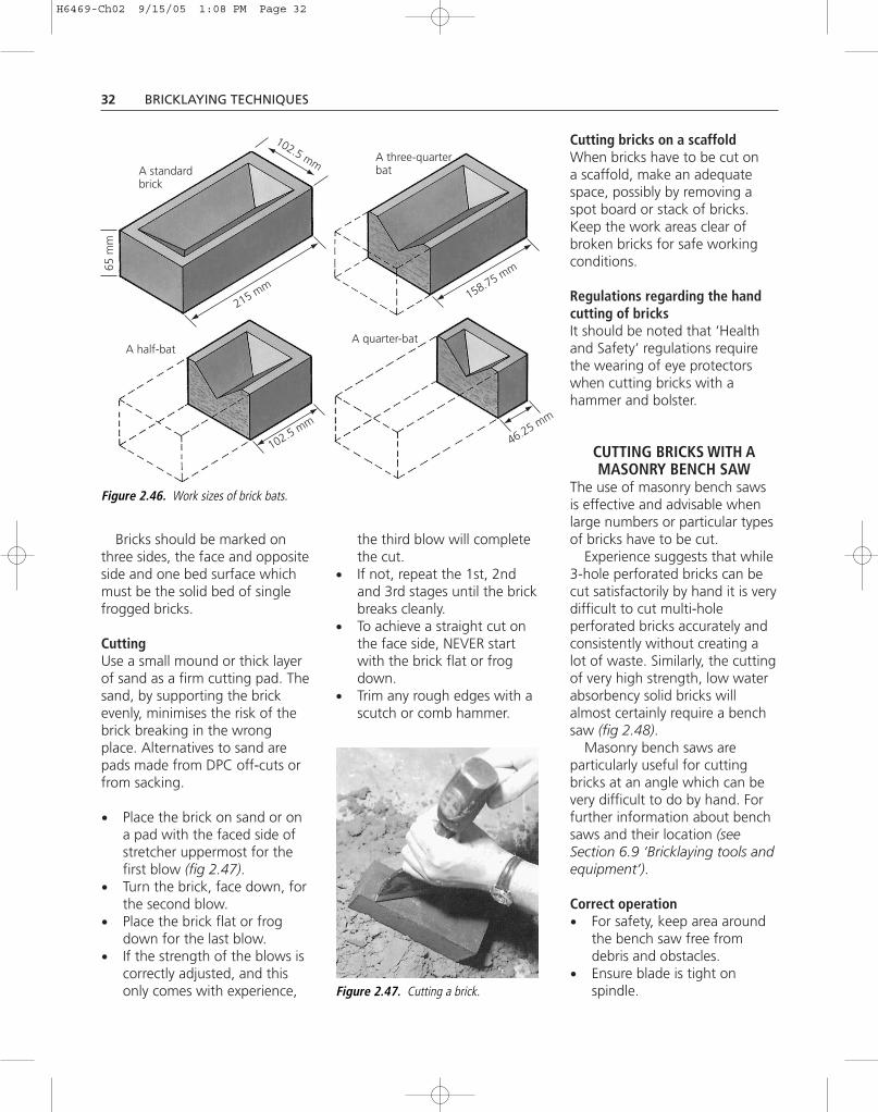
Measurement and marking ofbricks for cuttingA simple brick gauge(fig 2.45) will aid fast, accuratemarking when many brickshave to be cut, as for instancewhen building broken bond infacework. Accurate, cleancutting will help to maintainneat and plumb perpends.The work sizes of brick batsare shown in figure 2.46.
2.5 CUTTING BRICKS
Figure 2.43. Brick with fire crack.
This portionis very weak
Figure 2.44b. An incorrectly cutfrogged brick.
158.75 mm
102.5 mm
46.25 mm
Figure 2.45. A typical brick gauge.
Figure 2.44a. A correctly cut froggedbrick.
H6469-Ch02 9/15/05 1:08 PM Page 31
32 BRICKLAYING TECHNIQUES
Bricks should be marked onthree sides, the face and oppositeside and one bed surface whichmust be the solid bed of singlefrogged bricks.
CuttingUse a small mound or thick layerof sand as a firm cutting pad. Thesand, by supporting the brickevenly, minimises the risk of thebrick breaking in the wrongplace. Alternatives to sand arepads made from DPC off-cuts orfrom sacking.
• Place the brick on sand or ona pad with the faced side ofstretcher uppermost for thefirst blow (fig 2.47).
• Turn the brick, face down, forthe second blow.
• Place the brick flat or frogdown for the last blow.
• If the strength of the blows iscorrectly adjusted, and thisonly comes with experience,
the third blow will completethe cut.
• If not, repeat the 1st, 2ndand 3rd stages until the brickbreaks cleanly.
• To achieve a straight cut onthe face side, NEVER startwith the brick flat or frogdown.
• Trim any rough edges with ascutch or comb hammer.
Cutting bricks on a scaffoldWhen bricks have to be cut ona scaffold, make an adequatespace, possibly by removing aspot board or stack of bricks.Keep the work areas clear ofbroken bricks for safe workingconditions.
Regulations regarding the handcutting of bricksIt should be noted that ‘Healthand Safety’ regulations requirethe wearing of eye protectorswhen cutting bricks with ahammer and bolster.
CUTTING BRICKS WITH AMASONRY BENCH SAW
The use of masonry bench sawsis effective and advisable whenlarge numbers or particular typesof bricks have to be cut.
Experience suggests that while3-hole perforated bricks can becut satisfactorily by hand it is verydifficult to cut multi-holeperforated bricks accurately andconsistently without creating alot of waste. Similarly, the cuttingof very high strength, low waterabsorbency solid bricks willalmost certainly require a benchsaw (fig 2.48).
Masonry bench saws areparticularly useful for cuttingbricks at an angle which can bevery difficult to do by hand. Forfurther information about benchsaws and their location (seeSection 6.9 ‘Bricklaying tools andequipment’).
Correct operation• For safety, keep area around
the bench saw free fromdebris and obstacles.
• Ensure blade is tight onspindle.
102.5 mm
158.75 mm
215 mm
102.5 mm
46.25 mm
A three-quarterbat
A quarter-bat
A standardbrick
A half-bat
65 m
m
Figure 2.46. Work sizes of brick bats.
Figure 2.47. Cutting a brick.
H6469-Ch02 9/15/05 1:08 PM Page 32

KEEPING BRICKWORK CLEAN 33
• Check trolley moves freely onthe rails.
• Ensure an adequate supply ofwater in the machine.
• Clearly mark bricks to be cut,as described in ‘Measurementand marking’ in this section.
• Put on ear and eye protectorswhich are required by law butalso wear gloves, waterproofapron and boots.
• Place brick on the slidingtable and offer up so that theblade is central over thecutting mark. Secure brickwith fixing clamp.
• Turn on power to startmachine and check that theblade turns evenly and freefrom wobble.
• Offer the brick on the slidingtable to the rotating blade,apply pressure to the spring-loaded foot pedal to draw theblade down on the brick. It isimportant to ‘let the machinedo the work’. A little evenpressure, keeping the motorrevolutions even, is enoughto guide the blade throughthe brick.
• Keep fingers clear of blade,never look away whileusing saw.
• If sparks are emitted it usuallymeans insufficient water isreaching the blade.
• When the brick is almost cutthrough, release pressure
so that chipping doesnot occur.
• When cutting is complete,switch off, unclamp the brickand leave to dry before use,as, if saturated, the brickfaces may become smearedwith mortar.
• Change the water beforeeach change of brick. Light,buff bricks, for instance, maybecome stained if cut afterblack bricks.
NOTE: An approvedCautionary Notice (AbrasiveWheels Legislation) must bedisplayed for easy readingby operatives.
Figure 2.48. Bench saw.
KEY POINTS
■ Always use a pile of sand orother pad when fair cutting.
■ Prepare a space when cutting onscaffolding.
■ Use a gauge for quick, accuratemarking.
■ Apply bolster to face side first.
■ Do not strike too hard withbolster.
■ Select technique to suit type ofbrick.
■ Follow all safe workingprocedures when operating abench masonry saw.
2.6 KEEPING BRICKWORK CLEAN
Well designed, specified andotherwise skilfully built facingbrickwork can becomedisfigured by mortar stainsunless care is taken to workcleanly and protect materialsand finished work.
This section is mainly aboutgood trowel technique andcontrol of mortar consistencyto minimise such staining.
But it also refers to othertechniques, describedelsewhere in this book.
TROWEL TECHNIQUECross jointsApply mortar deftly to the end ofbricks so that faces are keptperfectly clean while filling the
cross joints completely tomaximise rain resistance(figs 2.49a & b) (see Section 6.7‘Rain resistance of cavity walls’).
Bed jointsSpread mortar fully acrossthe wall, but let none droopand stain the facework below.Do not deeply furrow(figs 2.50a & b).
H6469-Ch02 9/15/05 1:08 PM Page 33

34 BRICKLAYING TECHNIQUES
To avoid smearing the bricks inthe course below, gather thesurplus ‘squeeze’ of bed jointmortar produced as each brick is
pressed down to the line. Dothis with the trowel blade,making a ‘cutting’ action alongthe line of the bed joint,
horizontally not upwards(figs 2.51a & b).
Do not put too much beddingmortar on the wall. It willincrease the risk of wetting thebrick face and can lead toexcessive tapping whichencourages water towards theface. Estimating the correctquantity of bedding mortar andspreading it efficiently is animportant training aspect(fig 2.52).
Point the trowel along the wallwhen tapping bricks down sothat any mortar dropping fromthe blade falls on the bed(fig 2.53a). If the trowel is heldacross the wall, mortar can dropon the face (fig 2.53b). Takegreater care as you modify yourtrowel technique to reach higheras the wall rises.
MORTARSExcessively wet mortar, whethersite-mixed or delivered in tubs,retarded and ready-to-use(see Section 4.1 ‘Mortars’),is a common cause of dirtybrickwork.
In order to press bricks downby hand, bricklayers need smoothworkable mortars, but if theycontain too much water orplasticising admixtures they willbe ‘sloppy’, causing even themost skilful bricklayers to smearthe face.
Bricklayers are responsible foradjusting the consistency andworkability of mortars to suit thetype of bricks being used. Butthey must not, without thepermission of the architects orengineers, adjust the proportionsof cement, lime and sand as thiscan reduce the strength ordurability of mortars.
Figure 2.49a. Apply mortar cleanly toend of bricks.
Figure 2.50a. Acceptable lightfurrowing.
Figure 2.51a. Correct cutting action. Figure 2.51b. Incorrect cutting action.
Figure 2.50b. Unacceptable deepfurrowing reduces load-bearing capacity.
Figure 2.49b. Avoid smearing the face.
H6469-Ch02 9/15/05 1:08 PM Page 34

KEEPING BRICKWORK CLEAN 35
Sand for mortarsMortars should be made fromwell-graded sand containing fine,medium and coarser particles(see Section 4.1 ‘Mortars’fig. 4.3). Well-graded sands usedin mortars help retain mixingwater long enough for themortar to develop its maximumstrength, durability and adhesion.Sand containing only largerparticles makes ‘hungry’ or‘short’ mortar, allowing mixingwater to ‘bleed out’ on the spotboard and/or down the wall face.Factory-produced mortars fromreputable suppliers can beexpected to contain suitably
graded sands. Builders’merchants usually refer to suchsands as ‘building sands’.
Lime in mortarsLime helps to prevent mortarsdrying out too rapidly while inuse. This is considered to improvecohesion, workability andadhesion and in turn reduce therisk of smearing.
TYPES OF BRICKSBricklayers are responsible foradjusting the consistency andworkability of mortars to suit thetype of bricks. (For further
information on bricks seeSection 6.10 ‘Brick manufacture’.)
Higher absorbency bricksProviding such bricks are not wetat the time the mortar is spread,they will normally have sufficientsuction rate to absorb somewater immediately, therebyreducing the risk of mortarsrunning down the facework.
But, if the bricks are extremelydry, as in a hot summer, they mayabsorb water too quickly. In thatcase it is better to reduce theirsuction rate by wetting, ratherthan making the mortar too wetand ‘sloppy’.
Figure 2.52. Judge the right quantity of bedding mortar and spread evenly.
Figure 2.53a. Mortar drops on bedof brick.
Figure 2.53b. Mortar may dropdown face.
Figure 2.54. A typically high absorptionbrick with a high suction rate when dry.
Examples of such bricksare some machine-mouldedstock and handmade bricks(fig 2.54).
Lower absorbency bricksSuch bricks generally have a lowsuction rate and absorb very littlewater from mortars as they arespread. When using such bricksbricklayers should adjust theconsistency of mortars toproduce a less ‘sloppy’ mix inorder to prevent its runningdown the face.
Examples of such bricks areextruded wire-cut bricks(fig 2.55).
H6469-Ch02 9/15/05 1:08 PM Page 35

36 BRICKLAYING TECHNIQUES
Textured bricksDragwire and other texturedbrick faces tend to pick upmortar more readily than smoothfaces during bricklaying.
To reduce this risk, remove the‘squeeze’ of excess mortar insmaller amounts by two or threehorizontal passes of the trowel asthe brick is squeezed down,rather than a single pass whichtends to pile mortar on the face.
OTHER TECHNIQUESGood trowel technique alone isnot enough. Protect bricks frombecoming very wet from rain andground water when in store and
loaded-out on the scaffolding. Ifmedium to low absorbency bricksare very wet it becomes moredifficult to avoid smears (SeeSection 1.3 ‘Handling, storageand protection of materials’).
Completed facework shouldalso be protected to prevent rainfrom washing fine particles ofcement, lime and pigments fromfresh mortar.
Plinths and other projectingbrickwork should be protectedfrom mortar droppings. Scaffoldboards next to facework shouldbe cleared of mortar and turnedback during rain, and overnight(see Sections 1.2 ‘Protection ofnewly built brickwork’ and 6.6‘Appearance’).
CONCLUSIONThe necessary cleaning down offacework at the end of acontract can be greatly reducedby good trowel technique andavoiding the use of ‘sloppy’mortars.
In addition, vulnerablefinished brickwork must beprotected from subsequentstaining by mortars andmaterials used by other trades.Mortar must be cleared fromscaffold boards and thosenearest the brickworkturned back to preventsplashing caused by rainfalling on them.
Figure 2.55. A typical low absorptionbrick with a low suction rate, especiallywhen wet.
KEY POINTS
■ Keep mortar workable but reducemixing water as much as possible.
■ Use well-graded building sand.■ Do not spread bedding mortar
too thickly.■ Remove surplus mortar from
face with horizontal cuttingaction of trowel.
■ Apply cross-joint mortarcarefully to end of bricks.
■ Do not tap bricksunnecessarily – press themdown to the line.
■ Although bricks may have to bewetted in hot dry weather donot lay bricks that are saturated.
2.7 FINISHING MORTAR JOINTS
The type of joint finish andthe skill and care with which itis carried out, profoundlyaffects both the appearanceand rain resistance ofbrickwork (see Sections 6.6‘Appearance’ and 6.7 ‘Rainresistance of cavity walls’).
Today, most brickwork is‘jointed’, which means thatthe joints are finished as the
bricklaying proceeds.‘Pointing’ of mortar jointsthat were raked out onthe day the brickworkwas built is not nowcommon. If pointing isspecified it is normallycarried out after thecompletion of bricklaying(see Section 2.8 ‘Pointing andrepointing’).
Joint finishing is usually left toa convenient moment. ‘Joint-upbefore you break for tea’ is theusual reminder from the foremanbricklayer or charge hand.Likewise, bricklaying willgenerally stop before the end ofthe day’s work to leave time forjointing-up.
This section stresses not onlythe importance of allowing
H6469-Ch02 9/15/05 1:08 PM Page 36

FINISHING MORTAR JOINTS 37
sufficient time for finishingjoints correctly but the need todo so at the right timesthroughout the working day.
APPEARANCE‘Good pointing can improvepoor brickwork but badpointing can spoil goodbrickwork’, is a saying wellknown to experiencedbricklayers. Similarly, carefulfinishing of mortar jointing canminimise the effect of smalldeficiencies in bricks andbricklaying but careless jointfinishing can make them lookworse.
Jointing-up is a critical part ofbuilding facework and is notsomething to be ‘dashed off’apart from the main operation ofbricklaying. It considerably affectsthe permanent appearance offacework as almost one fifth ofthe total surface consists ofmortar joints.
Probably the most importantaspect of jointing-up is to avoidsmudging the bricks or blocks(see Section 2.6 ‘Keepingbrickwork clean’).
TIMINGTiming is probably the mostimportant aspect of jointing-up,particularly when making a neatflush joint without smudging thefacework.
The right time to joint-up isdetermined by both the suctionrate of the bricks and weatherconditions at the time the bricksare laid.
At one extreme, bricks of lowwater absorption that are verywet will have a low suction rate.The bricks will tend to ‘float’,
and the mortar will dry slowly,especially during wet or coldweather.
At the other extreme, highwater absorption bricks that arevery dry will have a high suctionrate and the mortar will dry outvery quickly, possibly before abond with the bricks has fullydeveloped.
To avoid these extremeconditions all bricks should beprotected from saturation, and inhot, dry weather the suction rateof higher absorption bricksshould be reduced by dockingor lightly spraying so that thesurface is left damp rather thanwet.
During summer months it isusually necessary to joint-upevery two or three courses in alength of walling typically builtby one bricklayer. In winter,twice only in a lift of brickworkmay be appropriate. The mortarshould be ‘soft’ enough for thejointing tool to leave a smoothsurface and to press the mortarinto contact with the brick arrisesin order to maximise rainresistance.
Trying to finish a mortar jointwhich is too dry, and pressingtoo hard with the jointer can‘blacken’ the joint face and leavea crumbly surface (fig 2.56).
Jointing-up too soon spreadsthe mortar and leaves a roughjoint surface (fig 2.57)Northamptonshire bricklayers say‘Wait until the joints have“hazelled off” a bit before youjoint-up’.
TECHNIQUEWhen ‘ironing in’ to give joints a‘bucket handle’ finish forexample, each bricklayer must
use the same diameter jointerfor consistency (fig 2.58). Thejointing tool must remain incontact with brick arises above
Figure 2.56. Jointing-up late can disturband crumble mortar surface or ‘blacken’ itby over-rubbing.
Figure 2.57. Jointing-up too early cansmear mortar and leave a rough surface.
Figure 2.58. Correct use of jointer.
H6469-Ch02 9/15/05 1:08 PM Page 37

38 BRICKLAYING TECHNIQUES
and below the bed joints andeach side of cross joints,otherwise ‘tramlines’ will be left(fig 2.59).
Cross joints must always befinished first whatever the jointfinish. The only exception to thisrule is when applying tuckpointing.
If square recessed joint finish isspecified, the use of ‘chariot’jointers (fig 2.60) or other depthgauges (fig 2.61) will help eachbricklayer to rake out to the samedepth. After raking out, therecessed mortar should normallybe ‘polished-up’, not left rough,in order to maximise the rainresistance of the joint. Use theinsert in a chariot jointer or asquare jointing tool.
If a weather struck finish isrequired, all cross joints must beinset the same side, usually theleft-hand side, by both right andleft-handed bricklayers (fig 2.62).Otherwise there will be distinctdifferences in appearance due toshadow lines.NOTE: With weather struck andcut pointing the depth of insetand ‘boldness’ of mortarprojection must be consistent.The thickness of the pointing
trowel is sufficiently bold.(see Section 2.8 ‘Pointing andrepointing’)
It may appear easy to achievea high standard of simple ‘flush’jointing but experience, care andattention is required if the jointsare to be left looking truly flush.
If finished too soon ‘wet’mortar will be smeared on theface of the bricks. If left too late,so that the mortar is too ‘dry’, itwill crumble and leave ‘misses’and an incomplete and unevenlycompacted surface.
Steel tools are used to finish thesurface of bucket handle, struckweathered and also give the finalpolish to square recessed joints.Steel tools are not used to finishflush joints as they tend to leaveconspicuous tooling marks. Apiece of hardwood, about200 mm long by 50 mm wide and10 mm thick with a half-roundedend, rather like a doctor’s spatula,is commonly used to flatten themortar joints. Great care shouldbe taken to ensure that both crossjoints and bed joints are left trulyflat and not ‘dished’.
A very light brushing willremove fine crumbs of mortar andleave a matt surface rather than apolished one as from a steel tool.
The comments on ‘brushing’, insection 2.8 ‘Pointing andrepointing’, applies equally tojointing. Generally, delay brushinguntil the end of the day in summerand leave until the next day indamp or cold winter weather.
ATTENTION TO DETAILCare is needed when finishingjoints at external angles (fig 2.63).Finishing of joints in internalangles must carefully emphasisethe tie-bricks or bonding at thesepoints, finishing alternately to leftand right (fig 2.64), not with astraight joint (fig 2.65).
Take care to continue with thejoint finishing under projectingbrick-on-edge sills, under copingsand the soffits of soldier archesover openings.
Figure 2.59. Incorrect use of jointerleaving ‘tramlines’.
Figure 2.60. Chariot jointer showingspike for raking joints to a consistentdepth.
Figure 2.61. An improvised but effectivedepth gauge.
Figure 2.62. Forming a weather struckjoint.
H6469-Ch02 9/15/05 1:08 PM Page 38

POINTING AND REPOINTING 39
Immediately after a brick hasbeen laid the surplus mortar iscut flush with the face. Themain purpose of anysubsequent joint finishing is to
improve the rain resistance ofthe wall by compacting thesurface of the mortar andpressing it into close contactwith the bricks.
At vertical movement jointsin facework leave a vertical,parallel sided 10 mm space formastic sealant. Do not leavegaps at the ends of bed jointsso that the sealant spreads togive unsightly ‘mouses’ ears’(fig 2.66).
MORTARBuilding sand that ispredominantly fine grained willproduce a closer textured,smoother and denser surfacefrom the action of the jointerthan will coarser sands. Lime inbricklaying mortar tends toproduce a more compact surfacethan when air entrainingplasticisers are used.
Figure 2.63. Pay attention to externalangles.
Figure 2.64. Correctly finished internalangle.
Figure 2.65. Incorrectly finishedinternal angle.
Figure 2.66. ‘Mouses’ ears’ in a verticalmovement joint.
KEY POINTS
■ Take care to judge the besttime to joint-up.
■ All bricklayers should use thesame profile jointing tools andtechnique.
■ Take particular care at angles,sills and vertical movementjoints.
■ Use fine grained sands for finejoint finishing.
■ Brush lightly if at all.
2.8 POINTING AND REPOINTING
JOINTINGToday most face brickwork is‘jointed’ which means that thejoints are finished as the workproceeds and should require no
H6469-Ch02 9/15/05 1:08 PM Page 39

40 BRICKLAYING TECHNIQUES
further attention at the end ofthe day.
POINTINGOccasionally architects will specifythat the joints be ‘pointed’ inorder to achieve a particular effect.
When new brickwork is to bepointed, all joints are raked 12 to15 mm deep on the day the wallis built ready to receive a differentmortar at a later date (fig 2.67).
The pointing is usually adifferent colour and may berequired to have a particularprofile, e.g. flush, struckweathered, half-round tooled orsquare recessed, all of which canalso be formed as a jointingprocess as the work proceeds(fig 2.68).
In this section, only weatherstruck and cut pointing will bedescribed, as it is a commonlyused profile for pointing andrepointing (fig 2.69). Also, it is
not practicable to form theprofile as part of the jointingprocess because the bricklayers’rhythm would be disruptedwhilst they stopped to apply,to every joint, extra mortar toform the profile. Forming aweather struck and cut finish is apointing, not a jointing operation.
TOOLSPointing trowels with blades 50,75, 100 and 150 mm long areused with a hand held hawk. Theshortest trowel is known as a‘dotter’ (fig 2.70).
THE PROCESSPointing is seldom popular withbricklayers, for being a staticoperation and requiring patience,care and attention it can be acold job during the winter.
Figure 2.67. Raked out joints.
Figure 2.69. Weather struck and cutpointing.
Figure 2.68. Typicaljoint profiles exceptingstruck and cut. (See alsoinside front cover.)
H6469-Ch02 9/15/05 1:09 PM Page 40

POINTING AND REPOINTING 41
Specialist pointing gangs areusually engaged for large areasof walling.
Careless pointing can spoilgood brickwork and conversely,good pointing can considerablyimprove ‘questionable’ facework.
Before pointing begins, loosedebris should be removed fromthe joints with a dry brush andthe work ‘wetted down’ to adamp condition. Wetting downreduces the amount of watersucked from the pointing mortar
by the existing brickwork whichif too great would preventcomplete hydration resulting in aweak crumbly mortar.
Cross jointsCross joints are filled first. Thepointing mortar should be firmlypressed home and compactedwith the inset on the left-handside and the ‘cut’ on theright-hand side so that every jointlooks the same width (fig 2.71).
Both left and right-handedbricklayers must inset on the leftand cut on the right to preventthe completed wall face having apatchy appearance (fig 2.72).
The inset and cut projectionmust not be exaggerated. In bothcases 1 mm is enough.
When the cross joints arecompleted over about 1 m2 of wallsurface, the top and bottom ‘tails’of mortar should be pressed away.
Bed jointsA trowel with a longer blade isused to apply the mortar to bedjoints.
Press the pointing mortar firmlyinto the joints, insetting just 1 mmat the top and ‘cut projecting’ thelower edge by the same amount.Sloping or ‘weathered’ surfaces,by shedding rainwater morereadily, are considered to providebetter rain resistance thanrecessed or even flush joints(fig 2.73).
Bed joints are cut guided by apointing rule, a wooden straightedge with spacing blocks to holdit off the surface of thebrickwork. Joints may be cutusing the point of a towel(fig 2.74a), but some bricklayersfind that a specially made cuttingtool known as a ‘Frenchman’ ismore manageable (fig 2.74b,c).
Figure 2.70. 50, 75, 100 & 150 mm trowels.
Figure 2.71. Cross joint.
Figure 2.73. Filling bed joints.Figure 2.72. Cutting a cross joint.
H6469-Ch02 9/15/05 1:09 PM Page 41

42 BRICKLAYING TECHNIQUES
It is important to cut themortar bed joints so that they allappear to be the same width.
TimingNeither cross joints nor bed jointsshould be cut until the mortarhas stiffened a little. This willensure a clean cut. Theabsorption of the bricks andweather conditions willdetermine the timing.
Bricks with a high absorptionwill allow cutting to be carriedout sooner than bricks of lowabsorption. Similarly, cutting canbe carried out sooner in warmdrying weather than in colddamp weather.
Pointing should not be carriedout if frost is likely or after a longperiod of frost if the bricks arestill frozen.
External anglesBed joints should be neatlyformed at corners and reveals(fig 2.75).
BrushingAt the end of the day a lightbristle brush may be used toremove any crumbs of excessmortar left after cutting the
Figure 2.74a. A pointing rule and trowel in use.
Figure 2.74b. A pointing rule and Frenchman.
Figure 2.74c. A pointing rule and Frenchman in use.Figure 2.75. External angles at cornersand reveals.
H6469-Ch02 9/15/05 1:09 PM Page 42

POINTING AND REPOINTING 43
joints. Great care should betaken to avoid making brushmarks in the soft mortar. Itmay be advisable to leavebrushing the pointing whichhas been completed late in theday, until the following morning(fig 2.76).
REPOINTINGBefore old brickwork is repointedthe cause of the deteriorationshould have been established.It is usually the result of slowerosion over many years but if itis due to, say, sulfate attack onthe mortar the cause should beremedied first.
The sequence of operations forrepointing old brickwork isvirtually the same as for newwalling, except that the jointswhich may be heavily weatheredor perished must be cut out firstusing a hammer and bolster withcare in order to cause minimaldamage to the bricks. It isessential that the recess soformed be left square. The brickedges should be absolutely freeof old mortar so that the newmortar (fig 2.77) can bondeffectively with the bricks.
The recess should be no lessthan 10 mm and no more than15 mm deep. If it is too shallow
the mortar may not have asufficient bond with the bricksand if it is too deep it may bedifficult to force the mortar in forthe full depth.
At the same time lichen andmoss should be removed bycareful brushing so as not todamage the bricks.
The brickwork should then bedampened, not soaked, andwork should proceed asdescribed for pointing newbrickwork.
MORTAR MIXESPointing mortars should be ‘fatty’and cling to the trowel. This canbe achieved by the addition oflime which improves thecohesiveness of mortar, its bondwith the bricks and the rainresistance of the brickwork.
Under normal conditions ofexposure a 1:1:6cement:lime:sand mix will bespecified as appropriate. Withcalcium silicate bricks a 1:2:9 mixmay be required. With very densebricks only and in situations ofextreme exposure the mortarmay be 1:1/4:3.
In general the mortarshould be no stronger thanthat used in the constructionof the wall.
MORTAR BATCHINGWhether the cement, lime andsand are all mixed on site orcement is added to premixedlime:sand, careful measurementfor every batch is essential ifmortar colour variations andpatchy brickwork are to beavoided. It is virtually impossibleto achieve satisfactory results ifmeasurement or gauging is doneby the shovelful.
Consistent results are alsodifficult if pigments are added onsite. The use of premixedlime:sand for mortars is the onlypracticable way of producingcoloured mortars.
Figure 2.76. The result of brushing jointstoo soon.
10–15 mm
Figure 2.77. Recessing joints forpointing.
KEY POINTS
■ Remove lichen and moss fromold brickwork before repointing.
■ Ensure joints are recessed squareand all old mortar and dust isremoved before pointing orrepointing begins.
■ Dampen the wall by wettingdown and allow to drain beforestarting work.
■ Press mortar into crossjoints first, followed by thebed joints.
■ Do not exaggerate the inset orprojection of the mortar.
■ Cut joints so that all appear thesame size.
■ Do not brush the finished worktoo soon.
H6469-Ch02 9/15/05 1:09 PM Page 43

44 BRICKLAYING TECHNIQUES
The familiar brick shape hasproved to be the mostsuitable for building andmanufacture for over threethousand years, and it will bereferred to here as the‘standard’ brick.
Even so, from earliest timesspecial shapes have beenmade to fulfil functional anddecorative requirements andtoday their use has beenrevived to meet the need forattractive and enrichedbuildings. For the bricklayer,laying special shapes requirescare and attention if thearchitect’s design is to berealised in practice.
THE PURPOSE OF SPECIALSHAPES
To create shapes in brickworkwhich would be impossible,unsatisfactory or expensive usingonly ‘standard’ bricks.
DEFINITIONSBricks of special shapes and sizesSuch bricks are referred to inBritish Standards as ‘Bricksof special shapes and sizes’ ormore commonly as ‘specialshapes’ or even just ‘specials’(fig 2.78).
Standard specialsThe term ‘standard specials’refers to those shapes and sizesspecified in BS 4729(1). It doesnot imply that manufacturers orsuppliers generally hold themin stock.
Non-standard specialsThis term describes any bricks ofspecial shapes or sizes notspecified in BS 4729. They aresometimes referred to as‘purpose made specials’ or ineveryday speech as ‘specialspecials’.
AVAILABILITY AND STOCKSSome of the more commonlyused standard specials, e.g.single bullnose and cants andplinth headers and stretchers arestocked by suppliers but theywill frequently be made toorder.
Some special shapes may takelonger to produce than‘standard’ bricks because theyare formed, dried, fired andhandled by different processes
and in some cases new mouldsor extrusion dies will have to bemade. This should be taken intoaccount when programmingbrickwork requirements andplacing orders.
STORAGEAll ‘specials’ take longer toproduce and are more expensivethan ‘standard’ bricks and shouldbe carefully and systematicallystored and protected from rainin order to reduce damage andwastage and make it easier tofind particular types whenrequired.
Money spent on appropriatestorage is likely to bejustified, particularly as wasted‘specials’ can seldom be replacedquickly.
2.9 BRICKS OF SPECIAL SHAPES AND SIZES
Figure 2.78.
H6469-Ch02 9/15/05 1:09 PM Page 44

BRICKS OF SPECIAL SHAPES AND SIZES 45
BASIC FUNCTIONSSpecial shaped bricks may begrouped according to their mostusual function:
• for changes of direction atangles other than 90 degreese.g. ‘squints, external andinternal angles (doglegs)’.
• for changes in thicknessvertically, e.g. ‘plinth bricks’.
• for chamfered and radiusedcorners, e.g. ‘cant andbullnose bricks’.
• to stop, neatly and effectively,the freestanding end of a runof brickwork or to changefrom one profile to another,e.g. stops for ‘standard’, cantor bullnose brick-on-edgecappings.
• to return cappings andsoldier courses neatly andeffectively.
• for bonding brickworkwithout cutting ‘standard’bricks, e.g. ‘King and Queenclosers’.
• for tightly Curved brickwork,i.e. ‘radial bricks’.
• for arches. Tapered archbricks are available forbuilding semi-circular archeswith parallel-sided jointsbetween each arch brick.
NOTES:1. Many ‘specials’, because they
have single frogs or have atexture so that the brick has a‘top and bottom’, are availablein left-hand and right-handversions, e.g. king closers,cants, bullnoses, squints,angles and certain returns.
2. Because standard and specialshape bricks are sometimesformed or fired in differentways the colour or texture mayvary slightly. If this is thought
to be unacceptable thesupplier or manufacturershould be informedimmediately and certainlybefore the bricks are walled in.
SETTING OUTSquints, external and internal(dogleg) anglesWalls which include anglebricks should be set out to theface side as with any facework.The same rules of bondingmust be applied at obtuse anglesas apply at right-angled corners(fig 2.79). The use of squints
instead of external angles givesa smaller face lap but it appearsto have proved adequate inpractice. Squints have anadvantage that being easier tomanufacture the angle is oftenmore accurate.
BS 4729(1) includes a rangeof angle bricks for internaland external angles of 30°, 45°and 60°. There is a choice ofsizes to turn the corner andmaintain bond in half lapped orquarter lapped bonding with orwithout the addition of closersor three-quarter bats.
Plinth bricksBonding should be set out sothat perpends align vertically
An external angle andcloser establish half-bond
An external angle andthree-quarter batsestablish half-bond
An internalangle (dogleg)establisheshalf-bond
A squint brickestablishes half-bond
A squint brick andcloser establishesquarter-bond
Figure 2.79. Examples of bonding of angle bricks at a quoin.
H6469-Ch02 9/15/05 1:09 PM Page 45

46 BRICKLAYING TECHNIQUES
from the base below theplinth, through the plinthcourse to the walling above(fig 2.80).
This requires pre-planning by thesupervising bricklayer before workbegins, using pencil and paper toensure that the correct quoin
bricks are used, as a mistake willbe permanent and conspicuous.
Pre-planning ensures that anybroken bonding is at or near thecorner below the plinths, then,when the plinth courses havebeen bedded, the brokenbonding at the cornerautomatically disappears.
Cant and bullnose bricksSetting out is the same as forwalls with normal bricks at thecorners but special attentionshould be paid to plumbing thecorners as indicated below.
PLUMBINGWhen plumbing single cant orbullnose bricks, simply tap thequoin headers and stretchersbackward or forward until thefaces next to the corner are trulyvertical at A and B (fig 2.81).
When plumbing squint orexternal angle quoin bricks theyshould be tapped along the lineof the wall in order to plumb thefaces, marked C and D (fig 2.82).
This skill in laying squint andexternal angle bricks needs to be
75
56 56
327
215
75
75
75
75
75
75
75
Figure 2.80. Bonding plinth bricks.
A B
Figure 2.81. Plumbingcant bricks at a quoin.
Plan first course
Plan second course
D
C
Figure 2.82. Plumbing angle bricks ata quoin.
H6469-Ch02 9/15/05 1:09 PM Page 46

BRICKS OF SPECIAL SHAPES AND SIZES 47
developed so that the angle lookstruly straight when viewed frombelow (fig 2.83).
LAYING TO LINESpecial thought must be given tofixing a line and pins when‘running-in’ a course of some‘special’ bricks (fig 2.84).
It is good practice to considerthe most obvious ‘sight line’ suchas the edge or arris of any courseof ‘specials’ which will beimmediately apparent to anyonelooking at the finished building.
HANDINGSome smooth faced specialshapes such as single cants andsingle bullnoses may be reversedwhen used for example on eitherside of an opening (fig 2.85).
This is not so with manytextured bricks which initiallylook and weather differently iflaid ‘upside down’ (fig 2.86). Forthese, separate right and lefthanded versions must be orderedand stored carefully for easy andobvious identification, butreference should always be made
Figure 2.83. A well plumbedsplayed quoin using textured andhanded, squint bricks.
Figure 2.84. Fixing line and pins whenrunning a saddle back coping.
Figure 2.85. Smooth cant bricksmay be reversible.
Figure 2.86. Textured cant bricksmust be handed.
H6469-Ch02 9/15/05 1:09 PM Page 47

48 BRICKLAYING TECHNIQUES
to BS 4729(1) to check the correctversion before placing an order.
External plinth returns areanother example where left andright handed versions arerequired (fig 2.87).
Right and left handed versionsof single frogged specials maybe specified for reveals toopenings where they have to belaid frog uppermost in order toresist heavy loads from a lintelabove. Alternatively, if theappearance of the special allowsit to be laid either way up thefrogs may be filled with mortarand allowed to set before it islaid frog down in the work.
Some manufacturers stamp‘LH’ or ‘RH’ as appropriate tohelp identification.
HOW TO IDENTIFY WHICHHAND – LEFT OR RIGHT?
The following method toidentify left and right handversions of specials is used inBS 4729(1).
When the special is placed onits normal bed surface and itsequivalent stretcher face viewed,if the modification of the shape isto or at the left hand end of thebrick it is a left hand brick. If it isto or at the right hand end it is aright version.
Do not identify right or lefthand by brick’s intended positionin the work.
STOP BRICKSThese provide a transition from aspecial shape to a ‘standard’brick (e.g. fig 2.88a). Left andright hand versions will berequired for some stop bricks(e.g. fig 2.88b).
STOP ENDSLarge bullnose and cant bricks(215 � 215 mm or 215 �159 mm) stop straight runs ofcant or bullnose bricks on edgeeffectively and securely (fig 2.89).
RETURN BRICKSThese allow a special shapeto be returned at rightangles neatly and securely(fig 2.90).
Lefthand
Righthand
Figure 2.87. External plinth returnsmust be handed.
Figure 2.88a. Doublebullnose stop.
Figure 2.88b. Singlebullnose stop (left hand).
H6469-Ch02 9/15/05 1:09 PM Page 48

BRICKS OF SPECIAL SHAPES AND SIZES 49
BONDING BRICKSOne of the essential skills of abricklayer is the efficient use ofhammer and bolster in cuttingbats and closers from wholebricks for bonding purposes.However, in order to save timeand wastage where largenumbers of these are required itis usually possible to obtain themspecially made (fig 2.91).
ARCH AND RADIAL BRICKSThe use of these specials forbuilding arches and curvedbrickwork is covered insections 5.3, 5.4 and 5.7.
Reference(1) BS 4729:2005 ‘Recommendations
for dimensions of bricks (includingthose of special shape)’.
Figure 2.89. Stop endto double bullnose.
Figure 2.90. Single cant return. Figure 2.91. Queen closer.
KEY POINTS
■ Check if any ‘specials’ arehanded.
■ Check whether purpose-madebats and closers are availableon site.
■ Protect all specials fromdamage and waste. They maybe difficult to replace.
■ Take particular care to plumbsquint and angle bricks.
■ Maintain perpends of facebrickwork through plinthcourses.
■ Consider the ‘sight line’ whenlaying a course of projecting‘specials’ to the line.
H6469-Ch02 9/15/05 1:09 PM Page 49