21 nov 2013 juergen thomas: atlas tracker upgrade: hybrid production and test setup at birmingham 1...
TRANSCRIPT

121 Nov 2013
Juergen Thomas: ATLAS Tracker Upgrade: Hybrid Production and Test Setup at
Birmingham
ATLAS Tracker Upgrade: Hybrid Production and Tests at Birmingham
John Wilson, Simon Pyatt, Sam Edwards, Juergen Thomas
(Birmingham)

221 Nov 2013
Juergen Thomas: ATLAS Tracker Upgrade: Hybrid Production and Test Setup at
Birmingham
Outline
Work in the Clean-Room (Simon): Hybrid Production Tests for Heated Curing
Measurements of Hybrids (Sam) Work on the Test System (Juergen):
Test Results from Hybrids produced at B’ham
Acknowledgement: We have a lot of support, both h/w and advice, from UK Tracker Upgrade collaboration, namely RAL, Liverpool, Cambridge, Glasgow(Peter Phillips, Bruce Gallop, Tony Affolder, Ashley Greenall, Bart Hommels,Andrew Blue etc.), and also from the B’ham Astro group.
3
Hybrid Panel heated plate study (Simon)
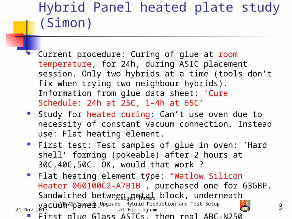
Current procedure: Curing of glue at room temperature, for 24h, during ASIC placement session. Only two hybrids at a time (tools don’t fix when trying two neighbour hybrids). Information from glue data sheet: ‘Cure Schedule: 24h at 25C, 1-4h at 65C’
Study for heated curing: Can’t use oven due to necessity of constant vacuum connection. Instead use: Flat heating element.
First test: Test samples of glue in oven: ‘Hard shell’ forming (pokeable) after 2 hours at 30C,40C,50C. OK, would that work ?
Flat heating element type: “Watlow Silicon Heater 060100C2-A7B1B”, purchased one for 63GBP. Sandwiched between metal block, underneath vacuum panel.
First glue Glass ASICs, then real ABC-N250 ASICs. Note: The panels used for this are ‘Rejects’, some have
been in drawers for years, poor coating and such.
21 Nov 2013
Juergen Thomas: ATLAS Tracker Upgrade: Hybrid Production and Test Setup at
Birmingham

Hybrid panel heated plate study (2)
Based on oven tests a target temperature above 30C is needed.Thermocouple on the heater and another one on the panel surface (On an ASIC pad)is connected to a temperature measurement unit.A dual power supply is connected and turned up to the maximum of 70 volts (370mA drawn)After over 2 hours the temperature settles at 34.4C, not as fast as hoped but it got there. Time to glue one glass ASIC hybrid.
Bare stencil used to put an additional glue sample directly on a hybrid as a “Prod and stir” sample

Hybrid panel heated plate study (3)
Ok, some real tests now. First test, temperature stability, how much control is needed.A proper temperature monitoring system is now used, a HP Data logger connected to a PCto capture the data. One day short test and one three day long test.
(Windows 95 PC!)

Hybrid panel heated plate study (4)
Third test. Produce samples for full testing. Real ASICs. Three heated hybrid cures done in a single session. Three room temperature hybrid curesfor comparison (Done later). A timer is added to start the heater early in the morning so the setup is ready to work on at 10am. Timer is from RS components, stock number 329-676 £10.69. Timer is only to turn heater on, heater is turned off manually.

Hybrid panel heated plate study (5)
Procedure goes smoothly.

8
Hybrid Panel heated plate study (Simon)
Tests with Glass ASICs were promising But big problem with panel with real ASICs:
Six hybrids in total glued and cured. On the three hybrids which underwent ‘heated
curing’, ASICs are fixed nicely, ie can only be removed using some force.
BUT the ASICs on three hybrids from ‘room temperature curing’ did fall off or could be removed easily !
Proper investigation ongoing… Microscope: Glue barely touched ASIC (no flat
top) -> Measure all items used (Sam). Some gaps ?
Influence of ‘reject’ hybrids: Poor surface, bent ? Did the heated curing help to prevent the chips
falling off the panel ?
21 Nov 2013
Juergen Thomas: ATLAS Tracker Upgrade: Hybrid Production and Test Setup at
Birmingham

9
Measurements of the Hybrids (Sam)
Sam is using the ‘Coordinate Measurement Machine’ (CMM) owned by the Astro group to precisely measure the hybrids. Precise to 5μm.
Initial challenge: Find a very good reference point. Used mainly ‘Gold pads’ for ‘touch-down pins’ on hybrid. All measurements relative to this reference (due to eg dust on surface under panel).
All measurements made using vacuum (hybrid held flat on panel).
Rather big variations from one chip to another on a hybrid (~40μm), chips also slightly ‘tilted’.
Investigating the tools used for assembly (which hold the chips in place during curing: ‘Pick-up Tool’). They may not be completely flat or wear-out over time (needs Quality Assurance (QA) procedure ?).
We have two such assembly tools, checking consistency between chip height (ie glue thickness) and tool dimensions/flatness.
21 Nov 2013
Juergen Thomas: ATLAS Tracker Upgrade: Hybrid Production and Test Setup at
Birmingham

Measurements: Inaccuracy in Pick-Up Tool (Sam)
Measurement shown on graph is this gap.
1 2 3 4 5 6 7 8 9 10360
370
380
390
400
410
420
430
440
Pick-Up Tool Profile
Top Row Hybrid - Far SideBottom Row Hybrid - Near Side
Heig
ht
of
Pic
k-U
p P
ad f
rom
the T
ouch
Dow
n P
in level (m
icro
ns)
Variation between highest and lowest ‘pad’ is 43 Microns
Pick-Up ‘Pad’
Touch down pin

Variation in Panel Surface Height (Sam)
1 2 3 4 5 6 7 8 9 10
-25
-20
-15
-10
-5
0
5
10
Variation of Surface Height Below ASIC's
Bottom RowTop Row
Heig
ht
in M
ircons
Measurements taken on the ‘pads’ below where an ASIC would be glued. There is a variation of 25 Microns between the high and low areas.
Panel surface measured from the gold disc’s used for the Pick-Up tool touch down pins

The highest ‘pad’ on the pick up tool is 429.25 Microns
The lowest ‘pad’ on the panel is -19.25 Microns
This could lead to a possible total gap of 448.5 Microns
The thickness of an ASIC is 325 Microns
This means a glue thickness of 123.5 Microns would be required for even partial contact with the ‘pad’ on the panel. Larger thickness of glue required to get a good amount of contact and therefore a strong bond.
Measurements: First Results (Sam)

1321 Nov 2013Juergen Thomas:
ATLAS Tracker Upgrade: Module ASIC Gluing and Test Setup
ASIC Tests (Juergen): ABC-N Functionality in a Nutshell
Tasks of the ABC-N chip (from specifications document):
“The chip must provide all functions required for processing of signal from 128 strips of a silicon strip detector in the ATLAS experiment employing the binary readout architecture.” (ie: Output is a yes/no for each strip)
1. Charge integration2. Pulse shaping3. Amplitude discrimination.
Threshold value for the amplitude discrimination is provided as differential voltage either from internal programmable DAC or from external source.
4. Outputs of discriminators must be latched either in edge sensing mode or in the level sensing mode.
5. At the start of each clock cycle the chip must sample the outputs from the discriminators and store these values in a pipeline until a decision can be made whether to keep the data.
6. Upon receipt of a L1 Trigger signal the corresponding set of values together with it's neighbours are to be copied into the readout buffer serving as a derandomizing buffer.
7. The data written into the readout buffer is to be compressed before being transmitted off the chip.
8. Transmission of data from the chip will be by means of token passing and must be compatible with the ATLAS protocol.

1421 Nov 2013Juergen Thomas:
ATLAS Tracker Upgrade: Module ASIC Gluing and Test Setup
Test Setup Status: HSIO
Reminder: HSIO (High-Speed Input Output) is Xilinx-4-FPGA-based board designed and produced by SLAC, it is the standard for testing Tracker ASICs, Hybrids and Modules. Firmware developed by UCL. Controlled by SCTDAQ s/w package (main developers: RAL), from Win7 PC.
HSIO ‘mimics’ real control systems and can capture and store output data from the ABC-N chips. Connection between HSIO and ABC-N chip is via a very small number of LVDS channels.
Initially connected a Hybrid from Liverpool: Connection goes in stages:
When starting SCTDAQ, S/W will report if hybrid responds Connection test: ‘st_nmask’ (command line) produced ‘saw
tooth’ triangle pattern, one triangle/tooth for each chip connected
Then can move to the serious tests (started from GUI): StrobeDelay and 3PointGain
SCTDAQ writes output into histograms (ps file), Root files and logs.

1521 Nov 2013Juergen Thomas:
ATLAS Tracker Upgrade: Module ASIC Gluing and Test Setup
News from the test system, in Poynting Basement (PB8):
New power supply (CPX400DP): ‘Remote controllable’ via USB from SCTDAQ S/W (this still needs to be set-up)
… and: The Unit Under Test is now a Birmingham- produced Hybrid !
(This panel, our label ‘B2’: 5 hybrids populated)
Test system with Hybrid (1)

1621 Nov 2013Juergen Thomas:
ATLAS Tracker Upgrade: Module ASIC Gluing and Test Setup
Overview of the setup (Win7 PC not on picture):
- Bottom: HSIO and Interface Board.
- Top-left: Hybrid, small vacuum pump for cooling (airflow) and holding hybrid flat on panel
- Top-right: New power supply, and Oscilloscope showing HSIO LEMO outputs (after LVDS-to-TTL conversion in FPGA).
Test system withHybrid (2)

171 Aug 2013Juergen Thomas:
ATLAS Tracker Upgrade: Module ASIC Gluing and Test Setup
Picture here: Liverpool Panel and Hybrid (‘Chip 6 not working’)
Left-hand connector: Datalines (8 LVDS channels).Extra power input for LVDS drivers (3.3V, 0.26A) (not always used)
Test system with Hybrid (3)
Right-hand connector: Power input 3.3V (drawing 4.4-4.8A). Serial powering.

18
Powering-up B’ham made hybrids Simon has produced (place&glue, cure and wire-bond)
10 hybrids with ABC-N 250 ASICs, on two panels (‘B1’, ‘B2’). B2 has generally ‘best bonds’ (last ones made, tricks learned).
Those two panels have passive components and connectors already in place (panels eg used in curing tests don’t).
Initial power-up: Each hybrid drew more than 5A (at 3.3V) and one or even two wires started to glow and burn-through. Power consumption dropped by some 0.5A after that.
BUT afterwards, they worked just as well as the Liverpool hybrid !
Investigation showed our wire bonding program has one wire differently than the Liverpool hybrid. We assume this caused a short and the wire burned through (ie ‘self-cured’).
As the ABC-N250 ASIC and hybrid is now quite an old system, we won’t make a fuss about this. But need to be sure to carefully match and update wire bonding programs from now on.
21 Nov 2013
Juergen Thomas: ATLAS Tracker Upgrade: Hybrid Production and Test Setup at
Birmingham

1921 Nov 2013Juergen Thomas:
ATLAS Tracker Upgrade: Module ASIC Gluing and Test Setup
Hybrid power-up: ‘st_nmask’ test
- SCTDAQ s/w setup modified to run in ‘Hybrid’ mode (before: Single-Chip testboard mode)
- ‘st_nmask’ is an important test to see if chips are responding to commands from the test system- One fully black triangle for
each chip on the Hybrid: All 20 chips responding fine.
- BUT big difference on how well/fast this works depending on supply voltage: No communication with Vcc=2.5V, very slow at 3V, better (faster) at 3.3V, best at 3.55V. With or without driver.Not sure I understand serial powering well.
2021 Nov 2013Juergen Thomas:
ATLAS Tracker Upgrade: Module ASIC Gluing and Test Setup
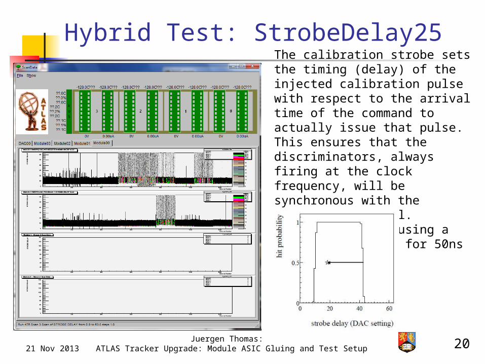
Hybrid Test: StrobeDelay25The calibration strobe sets the timing (delay) of the injected calibration pulse with respect to the arrival time of the command to actually issue that pulse. This ensures that the discriminators, always firing at the clock frequency, will be synchronous with the calibration signal. Scanning is done using a 6bit register (ie for 50ns clk: ~1ns steps)

2121 Nov 2013Juergen Thomas:
ATLAS Tracker Upgrade: Module ASIC Gluing and Test Setup
Hybrid Test: 3PointGain1pCThreshold Scan:The output of a channel for a given input of charge is measured systematically as the threshold is varied. The channel's response to an injected charge is to record a "1" (hit) or a "0" (no hit).
3PointGain:These tests are the threshold scan with 3 different levels of injected charge.
https://znwiki3.ifh.de/ATLAS/Projects/SCT/SCTUpgrade/DAQ/SCTDAQ

2221 Nov 2013Juergen Thomas:
ATLAS Tracker Upgrade: Module ASIC Gluing and Test Setup
Panel Number:206
Internal B'ham Label: Date of test: Tester: Test system sequence:
B2 (as on the sticker) 24/10/2013 JPT.x Stavelet.cpp / .x NoBCCSetup.cpp / st_nmask()
Hybrid #:
Chip type
Power-Up consumption [mA] Test consumption [mA] Reponding to s/w requests
Saw tooth pattern available Comments
0Glass n/a n/a n/a n/a Glass ASICs
1ABCN250 4760 4760Y (very slow) N
Very slow reaction to s/w access, but no saw tooth pattern. Same with LVDSDriver/3.55V. Info from Simon: 1 chip not bonded (bonding problems). No signal lines on one row. Not expected to work properly.
2Glass n/a n/a n/a n/a Glass ASICs3None n/a n/a n/a n/a Not populated (bad hybrid)
4ABCN2504990 (draws 67mA when PS ch is 'Off' !) 5120Y
Y (18 chips, slow, 3.55: fast)
Slow reaction to s/w access. 2 Chips not responding. 3.55V: Fast reaction !
5ABCN250 4300 4500Y Y (7 chips LVDSDriver)
LVDSDriver: Fast reaction to s/w access, 7 chips respond in tooth pattern. Hybrid looks good ! But wires which should have burned. haven't. To do: Power-up again and try to burn wire…
6ABCN250 4810 Y Y (16 chips, LVDSDriver)Only 16 out of 20 chips show in saw pattern (st_nmask). LVDSDriver: Fast access !
7ABCN250 40204800-5500 Y Y (all chips)Working. SD25/40 and 3PG1/2 histos look good. Info from Simon: Bonding etc all fine.
n/a = not applicable
Panel Number:202
Internal B'ham Label: Date of test: Tester: Test system sequence:
B1 (as on sticker).x Stavelet.cpp / .x NoBCCSetup.cpp / st_nmask()
Hybrid #:
Chip type
Power-Up consumption [mA] Test consumption [mA] Reponding to s/w requests Saw tooth pattern ok Comments
0ABCN250 5300 Y N
Bonding problems. Not expected to work well. Test: 'Saw pattern' very slow, no use for further tests.
1ABCN250 4000 Y N
Bonding problems. Not expected to work well. Test: 'Saw pattern' very slow, no use for further tests.
2Glass n/a n/a n/a n/a Glass ASICs3Glass n/a n/a n/a n/a Glass ASICs4Glass n/a n/a n/a n/a Glass ASICs
5ABCN250 1900 N N
No data connection. No further test. Info from Simon: Hybrid to Panel bonds failed, bend hybrid.
6ABCN250 4100 Y Y (all chips)
Bond glowed away after 2min. Saw tooth pattern ok. 2 chips noisy ? Info from Simon: Bonds not great, somewhat surprised it works.
7ABCN250 2700 N N
No data connection. No further test. Info from Simon: Hybrid to Panel bonds failed, bend hybrid.
B2
B1
Overview: Testing the two Birmingham Panels

231 Aug 2013Juergen Thomas:
ATLAS Tracker Upgrade: Module ASIC Gluing and Test Setup
Next Steps Simon’s ideas for curing process optimisations under discussion
with UK colleagues. Simon and Sam investigate carefully ‘Chips falling off’ problem.
Continuing with further hybrid tests (more systematic). Discuss results with experts (at RAL, Liverpool).
Need to fix our test system (Why do we need 3.3V or even 3.55V hybrid supply to ‘talk to’ chips ?) BUT don’t change a working system…
John and Juergen currently running a Yr4 project on hybrid tests, ie practical part of that project to be done early ’14. First ‘data taking’ next week. One task: Compare test results in Root from our two fully working hybrids with Liverpool’s.
Next Generation ABC-N chip on its way (wafers being diced currently): ABC-N 130. In Birmingham early next year ?
Many changes: Hybrid only with 10 ASICs, assembly tools changing, ie some plastic becoming metal.
UK colleagues are designing new testboards, hybrids, s/w interface.
ASIC runs at 1.2V, has 256 channels. Also a new HSIO (Artix-7 based).

241 Aug 2013Juergen Thomas:
ATLAS Tracker Upgrade: Module ASIC Gluing and Test Setup
Back-up Slides

Hybrid panel heated plate study
A glass ASIC hybrid is placed. A “Stir and prod” sample is placed which is then checked periodically. Sample forms a hard shell after two hours as seen on previous tests. Assembly is left for a few more hours, ASIC jig is removed, heater turned off and left to cure overnight.

261 Aug 2013Juergen Thomas:
ATLAS Tracker Upgrade: Module ASIC Gluing and Test Setup
Top-right: HSIO and Interface Board.
Bottom-left: One-hybrid- panel from Liverpool.
Flat-ribbon cable carries ‘Clk, Control, Gnd and Dataout’ signals (4 LVDS-pairs)
HSIO at Poynting basement
Test system with Hybrid (1)

Hybrid panel heated plate study
First test is to determine curing rates, this is done with test samples of glueon glass slides in an oven.
Several tests are done at 30oC, 40oCand 50oC. Samples are prodded everyhalf an hour.
All temperatures give the same result,a hard shell forms on the glue after 2 hours.
The hard shell is self supporting but not completelycured, it can be dented with a sharp point indicatingthat the glue interior is not completely cured. But could this be good enough to support the ASICswithout the ASIC vacuum jig once it has reachedthis state? Next stage is to design a system that can be usable.

Hybrid panel heated plate study
Currently the curing of the ASIC glue for the hybrid panels are done at room temperature.This is a study to determine if the panel can be heated to reduce the current cure time of 24 hours per ASIC placement session to speed up production.
Extract from TRA-DUCT 2902 datasheet:
So yes, the glue can be heat cured...
However the panel cannot be placed in an oven because of the vacuum hoses, so an alternative needs to be found. A proposed alternative is to use a heating plate that can be placed under the current curing setup. Flat heating elements are available.
Hybrid panel heated plate study
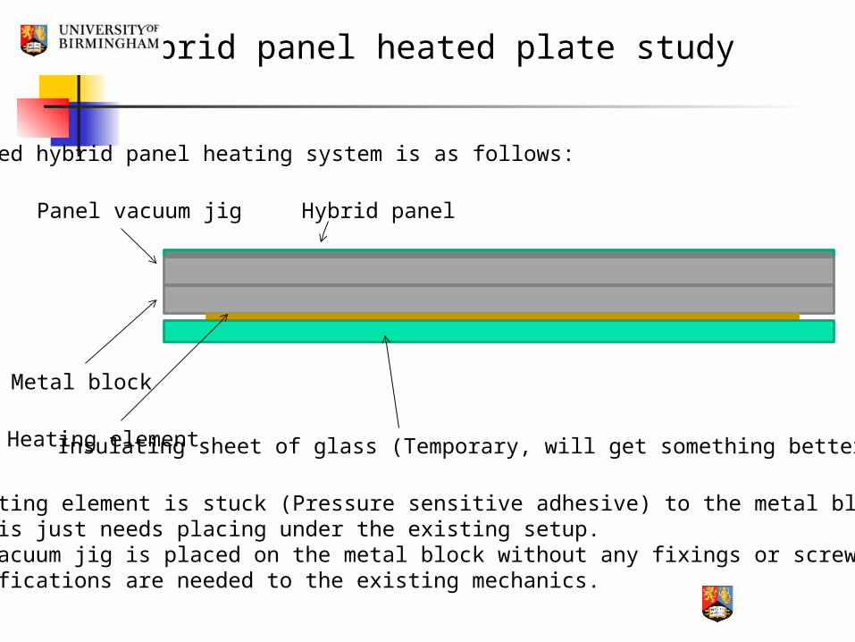
Proposed hybrid panel heating system is as follows:
Hybrid panelPanel vacuum jig
Metal block
Heating element Insulating sheet of glass (Temporary, will get something better later)
The heating element is stuck (Pressure sensitive adhesive) to the metal block, then this just needs placing under the existing setup.Panel vacuum jig is placed on the metal block without any fixings or screws.No modifications are needed to the existing mechanics.

Hybrid panel heated plate study
After some searching we found two companies who sell flat heating plates, Minco (Based in France) and Watlow (Based in Nottingham):
Minco:HK5529R101L12BUnit price : 185.00€Minimum Order Quantity : 25 piecesLead time : 7 to 9 weeks from order receipt.
4,625 Euros to buy a heater! Awful customer service, two months to get a quote.
Watlow:Helpful on the phone, willing to sell a single item. £63.20, bargain!

Hybrid panel heated plate study
Heating element is self adhesive, quick to fit on the heating block.A “K” type thermocouple is embedded into the heater.
Lets try it out...
Hybrid panel heated plate study
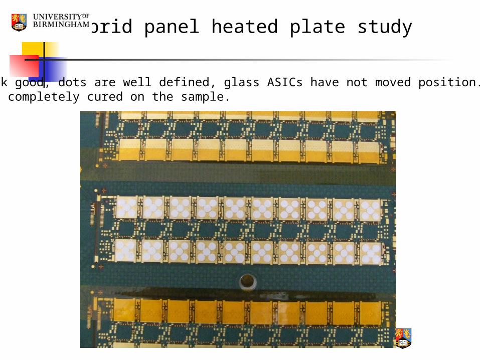
Results look good, dots are well defined, glass ASICs have not moved position. The glue is completely cured on the sample.

Hybrid panel heated plate study
3 day test. Temperature is very stable to within a degree, lucky.The procedure should work without requiring a controller.

Hybrid panel heated plate study
Second test. 2 Hybrid glass ASIC cure test. How stable is the temperature while the panel is being worked on. How smooth is the procedure to change over the ASIC jig.
Hybrid “Stir and prod”sample
Room temperaturecomparison sample
Procedure works well.Hybrid glue sample cures as predicted.glass slide sample still stirrable long after procedure is finished.

Hybrid panel heated plate study
There is no significant change in thetemperature during the procedure. Swopping the ASIC jig over takes 5 minutes.finished hybrids look good, includingthe positions of the ASICs.

Hybrid panel heated plate study
Disaster!Something is wrong with this panel.Height distance between jig pads and ASIC pads too big.
This ASIC fell off.
This ASIC cameoff easily.
This ASIC wasfairly firm.

Hybrid panel heated plate study
Conclusions (So far):
• Procedure requires some organisation and timing.However there is a two hour gap between placements and the final jig placement can be leftovernight with the heater on.
• Total expenditure is a £63 heater and a £10 timer. The metal plate and base are easy to make. The power supply type is already being used on the project.
• The heating system can be added to the current setup without any additional modifications.
• Positioning (Using visual inspection) of ASICs is the same as room temperature cured ASICs.
• CMM results need checking because of problems with last panel.
Next steps:• Shear testing in Berlin (We are already talking to this group).• A complete 8 hybrid gluing session (We have run out of panels and ASICs).• Other groups trying out the procedure.

381 Aug 2013Juergen Thomas:
ATLAS Tracker Upgrade: Module ASIC Gluing and Test Setup
Next Steps (OLD) Simon is soon moving to gluing and curing real ASICs – we have a
lot of ‘old’ prototypes, ABC-N 250, cut as dies (from Glasgow) Continuing with test system setup for hybrid, esp run more
complex tests, called ‘StrobeDelay’ and ‘3PointGain’. Discuss results with experts (at RAL, Liverpool)
Probably connect and test one of the hybrids we’ve assembled in B’ham
Further production preparations on-going: New power-supply units purchased by the UK groups (remote-
controllable: TTI CPX400DP), B’ham will receive one, needs to be integrated into HSIO test system, s/w can then control voltage/current.
Simon’s ideas for curing process optimisations under discussion with UK colleagues
John and Juergen are offering a Yr4 project on hybrid tests, ie practical part of that project to start January ’14
Next Generation ABC-N chip on its way: ABC-N 130. In Birmingham about end of year ? UK colleagues are designing new testboards, hybrids, s/w interface.