2064781 - pure.southwales.ac.uk
TRANSCRIPT

University of South Wales
2064781


RECOVERY OF POLY (ETHYLENE TEREPHTHALATE)
FROM USED X-RAY FILM
HARITH FARAJ NAODSH
A thesis submitted in partial fulfilment of the requirements
of the Unl versity of Glamorgan f or the degree of
Master of Philosophy
December 1992
Department of Science and Chemical Engineering
University of Glamorgan in collaboration with Concept
Recycling Limited

CONTENTS
PAGE
Acknowledgements (i)
Declaration (ii)
Certificate of Research
List of Figures
List of Tables (v)
Abstract (vii)
CHAPTERS
1. Introduction 1
2. Literature Survey 5
3. Properties of PVDC and PET
3.1 Poly(vinylidene chloride) PVDC3.1.1 Structure 173.1.2 Physical Properties 183.1.3 Solubility 183.1.4 Barrier Properties 193.1.5 Mechanical Properties 193.1.6 Degradation Properties 2O3.2 Poly(ethylene terephthalate) PET3.2.1 Structure 213.2.2 Physical Properties 223.2.3 Chemical Properties 233.2.4 Mechanical Properties 24
4. Experimental Work
4.1 Removal of Silver and SilverAnalysis 27
4.2 X-ray Base Plate 314.3 Determination of Papers and
Adhesive Tapes 354.4 Water Absorption 364.5 Removal of PVDC Coating 434.6 Determination of PVDC 494.7 Determination of I.V. 524.8 Tensile Strength and Elongation 65
5. Discussion of Results and Conclusions 70
6. Mass Balance and Heat Requirements of Reactor

6.1 Mass Balance Across the Plant 786.2.1 Construction of the Steam Jacket 826.2.2 Dimensions of Reactor 826.2.3 Agitator Design 836.2.4 Heat Transfer Area 856.2.5 Jacket Side Heat Transfer
Coefficient 856.2.6 Inside Heat Transfer Coefficient 876.2.7 Overall Heat Transfer Coefficient 896.2.8 Heating Time 90
7. Management and Recycling
7.1 Introduction 947.2 Marketing and Economy 957.3 Usage of PET 99
8. Description of a Recommended Plant and Control
8.1 Description of Recommended Plant 1028.2 Instrumentation and Control of
Plant 104
References 106
Appendix 108
Nomenclature list 111

ACKNOWLEDGEMENTS
I gratefully acknowledge the help of Dr. C. Davies and Dr.
G.J. Rees, as without their invaluable assistance and
directions this work would never have been completed.
My thanks are also extended to Mr G.J. Walters and Concept
Recycling Limited, who sponsored this project and for the use
of company facilities during the experimental stages of the
work.
I am especially grateful to my wife, Nerina, for her constant
encouragement throughout the years of this work.
(i)

DECLARATION
This is to certify that neither this thesis, nor any part of
it, has been presented or is being concurrently submitted in
candidature for any other degrees.
CANDIDAT^
DATE ..J5..Pecemb ?r .399?
(ii)

CERTIFICATE OF RESEARCH
This is to certify that, except where specific reference is
made, the work in this thesis is the result of the
investigation carried out by the candidate.
CANDIDATE
DIRECTOR OF STUDIES
DATE ,35..
(ill)

LIST OP FIGURES
No. Page
1 % of silver vs. year of manufacture 30
2 Infra-red spectra for PET 33
3 Infra-red spectra for CTA 34
4 Determination of IV of PET flake 58
5 Determination of IV of PET pellet 61
6 Determination of IV of PET blend 63
7 West European plastic consumption
in packing 96
8 West European PET price vs. cost 97
9 Process flow sheet 1S0
(iv)

LIST OF TABLES
No. PAGE
1 Physical properties of PVDC 18
2 Permeability of Saran to gases 19
3 Mechanical properties of PVDC 20
4 Physical and Chemical properties of PET
film 22
5 Chemical resistance of PET film 24
6 Mechanical properties of PET film 25
7 Silver content in the film 29
8 Density of film 31
9 Results of determination of paper and
tapes 35
10 Calculation of determination of paper
and tapes 35
11 Results of moisture permeability "2
hours immersion" 40
12 Results of moisture permeability "24
hours immersion" 40
13 Calculations of moisture permeability in
different samples 41
14 Calculations of moisture permeability in
different samples 42
15 The effect of different cutting methods
on the decoating 46X
16 Results of delamination/segregation 48
(v)

17 Determination of Poly (vinylidene
chloride) 51
18 Determination of Poly (vinylidene
chloride) 51
19 Determination of Poly (vinylidene
chloride) in de-silvered and delaminated
X-ray film 52
20 The I.V. of moist X-ray film (flake form) 56
21 The I.V. of dry X-ray film (flake form) 57
22 The I.V. of moist X-ray film (pellet form) 59
23 The I.V. of dry X-ray film (pellet form) 60
24 The I.V. of 50:50 blend 62
25 The I.V. of 60:40 blend 64
26 Tensile strength and elongation of X-ray
film 68
27 Tensile strength and elongation of 50:50
blend 69
28 I.V. results of PET film and PET pellets 72
29 Possible PET blends 76
30 % of raw material compounds 78
31 Mass balance across paper/film classifier 79
32 Mass balance across leaching reactor Tl 79
33 Mass balance across Tl-gelatin filter unit 80
34 Mass balance across silver recovery unit 80
35 Mass balance across hot tank (T2) 80
36 Mass balance across T2-filter unit 81
37 Mass balance across cold tank (T3) 81
(vi)

ABSTRACT
The thesis describes experimental work to remove primary
contaminants viz silver and poly (vinylidene)chloride (PVDC)
coating, from X-ray film and subsequent recovery of poly
(ethylene) terephthalate (PET) economically.
The thesis commences with a review of the literature,
concerning the recycling and recovery of (PET), from X-ray
films and related materials.
Following a discussion of the properties of (PVDC) and PET, a
programme of experimental work is outlined, for de-silvering
the X-ray film, removal of PVDC and recovery of PET.
From a consideration of the preferred experimental procedure,
an estimated materials and process costing is outlined, for a
proposed PET recycling plant.
Management and recycling, within the EC, specifically in
relation to the recovery of PET, is discussed, particularly
in relation to the legal restraints on the disposal of
plastics to land-fill sites.
A flow-sheet and description of the proposed recycling plant,
including control equipment and outline mass and energy
balances, concludes the thesis.
(vii)

CHAPTER ONE
INTRODUCTION
Over five million tonnes of plastic waste are produced each
year in Europe, Edwards' 1 ' . Part of this is collected with
domestic refuse and is recovered as heat. Only a small
fraction of it is used as a secondary raw material. New
procedures are needed to regenerate plastics reclaimed from
used X-ray film.
The purpose of this research
diagrammatically as follows:
work can be shown
X-RAY FILMPLASTIC TO LANDFILL OR INCINERATION
RECOVERYOF
PLASTIC
PURE SILVER

The production and consumption of X-ray film is increasing,
and this will generate considerable amounts of waste and
scrap that could be recycled, recovered, and transformed to
useful products.
In the UK alone over five million kg per annum of used X-ray
film and lithographic films from hospitals and the printing
industry, is being incinerated or land filled after
reclaiming the silver
The type of plastic in the base plate of an X-ray and
lithographic film is known as poly (ethylene terephthalate)
or PET .
Exploded Diagram of X-ray Film:
Layer No. 1 Poly (vinylidene) chloride (PVDC)
Layer No. 2 Emulsion of photographic salts and blue
dye
Layer No. 3 Base of Poly (ethylene terephthalate)
(PET)
LAYER NO 3
LAYER NO 1
] LAYER NO 2
D LAYER NO 1

Any recycled material is of value only if there is a market
for it, at a price that ensures profitability.
Polyethylene terephthalate polymer from X-ray and
lithographic film at the present time carrje'Sno commercial
value due to the following problems:
A The presence of Poly (vinylidene chloride) PVDC or
commonly known as SARAN, in both top and sub layer of the
base plate.
The plastics industry requires no greater than 10-30
parts per million residual poly (vinylidene chloride) to be
acceptable. The presence of PVDC in the PET, above the
acceptable limit, will cause malfunctioning of the extrusion
equipment , used in processing.
B The presence of photographic salts.
C Blue colouration will limit its applications.
D Low intrinsic viscosity (I.V.) of the poly (ethylene
terephthalate).
E Toxicity of the de-silvered film.
F The presence of paper, adhesive tapes and metal in the
used film.

G The necessity of drying the end product
H The lack of an efficient and economically viable recycling
process.
Failure to solve any one of the above problems will fail to
produce recycled clean*; poly (ethylene terephthalate) from
the X-ray film.

CHAPTER TWO
LITERATURE SURVEY
Various processes have been proposed for recovery of
terephthalic acid either as such or in the form of its
dimethylester, from poly (ethylene terephthalate). These
processes include saponification with alkalis or acids. Such
methods require reagents that make recovery expensive and
complicated, because of the various precipitations and
purifications involved.
Werke Witten^ 2 ^ investigated the esterifications of PET with
methanol under pressure yielding dimethyl terephthalate, but
the ester obtained does not have sufficient purity for use as
starting material in polycondensation. They also reported
that recovery of terephthalic acid from PET, using organic
solvent, is uneconomical and requires extensive plant, but
Hokik, Bacak and Pitat^ 3 ) developed technology that can
economically recover valuable chemicals such as terephthalic
acid (TPA) and ethylene glycol (EG) from waste poly (ethylene
terephthalate), (PET) by hydrolysis. The hydrolysis of PET
was achieved by the action of an aqueous alkali metal
hydroxide solution at a temperature of 100°C and two hours to
complete the reaction.
During the hydrolysis ethylene glycol was formed and the
authors ( 3 ) also observed that in an aqueous alcoholic
medium, having water - alcohol ratio of 1:1, higher yields of
TPA can be achieved, because of more limited losses in the

filtrate and due to lower concentration of the base in the
hydrolytic solution.
The reaction can proceed under atmospheric as well as under
increased pressure, the latter case enabling a lowering of
the alkali metal content to a minimum.
The authors ( 3 ) found that hydrolysis of PET can be carried
out under a pressure up to 25000 kN/m2 .
Moreno Garcia' ' described the leaching of silver from
crushed film with NaCN solution, a reaction classically used
in the hydrometallugical treatment of minerals containing
silver. The film pieces were treated in glass vessels with
NaCN solution. The solution was shaken and hydrogen peroxide
was added until the black colour of the film disappeared and
the clear blue of the PET appeared with the gelatine of the
film. The silver is simply recovered by electrolysis of the
final solution.
The investigators Muench, Notarbartolo and Spano' 5 ' found
that the scrap left over from the production of high
molecular weight synthetic polyesters, and scrap recovered
from the processing of polyesters to make them into finished
articles can be re-used. Whenever it is not contemplated
directly to reprocess it substantially according to known
methods, for instance by saponification with alkalies or
acids.

The authors( ' carried out experiments, by taking 50 parts
wt/wt of poly (ethylene terephthalate) scrap ground to a
powder and heated under agitation at about 200°C with 78
parts wt/wt of octyl alcohol for four hours. The reaction
product is filtered whilst hot and 120 parts wt/wt of clear
liquid are obtained to which was added 120 parts wt/wt of
methyl alcohol and 17 parts wt/wt of sodium methylate to give
a pH of 9-10. The precipitated dimethylester was washed with
methyl alcohol and dried, (45 parts wt/wt of ester are
obtained equal to a yield of 90%). The filtrate is distilled
at ambient pressure, recovering about 90% of the methanol.
The remaining solution is filtered and 1.5 parts of dimethyl
ester recovered as a mixture of octyl alcohol and ethylene
glycol, corresponding to 92% of the amount participating in
the reaction. A residue remains from which 3 parts wt/wt of
dimethyl ester are re-crystallised. The total yield was 98%.
A continuous process for recovery of dimethyl terephthalate
from poly (ethylene terephthalate) waste was achieved by
Marion, Measamer and Miller' 6 ' by:-
1) Dissolving and reacting the waste with ethylene glycol.
2) Reacting the products of step (1) with an excess of
methanol in the presence of an ester exchange catalyst,
elevated temperature and pressure to prepare dimethyl
terephthalate.
3) Deactivating the ester exchange catalyst before release
of the elevated pressure.
4) Distilling excess methanol.
5) Removing solids while the solution was still hot.
6) Recovering the dimethyl terephthalate.
The authors ( ' developed a continuous process where the poly
(ethylene terephthalate) film and ethylene glycol are
continuously fed to a two stage continuous glycolysis unit.
The first stage maintained at 220 - 225°C and atmospheric
pressure; the waste is dissolved and partially depolymerised
with ethylene glycol. The second stage, is maintained at
240°C and sufficient pressure to prevent boiling of the
reaction solution. The solution for the first stage is
further reacted with ethylene glycol to continue
depolymerisation. Sufficient ethylene glycol is fed to the
unit to degrade the waste into a liquid solution. The ratio
of ethylene glycol units to the terephthalate units in the
solution was about 1.3 to 2.0 (wt/wt).
Due to the great amount of material involved in PET, several
companies including Goodyear, Du Pont and Eastman Kodak, are
actively attempting to recycle PET wastes that are currently
landfilled or incinerated.
8

For this purpose three different types of technology have
been investigated by Barna, Johnstud and Lampartor ( 7 ) direct
re-use, remelting and chemical reduction. PET from bottles
can be directly re-used either by blending it with a virgin
stream and reforming or grinding it into small pieces for use
as filler material. The other method is re-melting, which
includes high pressure moulding, extrusion and
depolymerisation. The authors C7 ' also estimated expenses to
recover terephthalic acid and ethylene glycol.
In 1976, Fassell and Bridges ( 8 ) recovered silver and
terephthalic acid compounds from scrap film of a light
sensitive silver compound on a Mylar substrate by wet
oxidation at elevated temperatures and pressure. An aqueous
medium containing a silver complexing compound, such as amine
or ammonia was used, and the silver recovered by
electrochemical methods.
Then the solution was acidified by nitric acid to precipitate
the terephthalic acid compound which was filtered off and
then purified.
The residual process liquor contains biodegradable ethylene
glycol (EG) which is treated by standard biological sewage
treatment systems.
The authors obtained the results of the TA portion of PET
24.5%, silver content of the film 1.0% and other constituents
9.0%.
A process for recovering PET scrap for re-use was achieved by
Barkey and Lefferts( 9 ). This process involved initially
degrading the PET with a lower alkyl alcohol and subsequently
recovering glycol, dicarboxylic diester and alcohol from the
resulting reaction mixture by distillation.
The polyester was treated with at least 70% of the amount of
a phosphorus - containing compound, based on the total ester
- exchange catalysts in the mixture, and minimising the
repolymerisation reaction. Then the mixture was heated
directly to remove alcohol, water, glycols, etc from the DMT.
They also provided an improved process for recovering
dimethyl and ethylene glycol from poly (ethylene
terephthalate) scrap which comprises of:-
1) Forming a mixture comprising poly (ethylene
terephthalate), catalyst and methanol.
2) The mixture was treated to approach equilibrium in
accordance with the equation.
R COOR' + R" OH = RCOOR" + R' OH
(Acid) (Glycol) (Polymer) (Alcohol)
3) Treating the partially hydrolysed mixture with a
stoichiometric excess of a phosphorus - containing compound,
10

based on the total ester interchange catalyst concentration,
to deactivate the ester exchange catalyst and obtain dimethyl
terephthalate of sufficient purity to be directly utilisable
in polyester manufacture.
PET containing polyvinylidene halides are generally used as a
subbing or anchoring layer between a PET film base and a
gelatin layer containing halides or other silver compounds.
It has been found that the silver and silver compound
containing gelatin layer, can be separated cleanly from the
PET base with attendant removal of the polyvinylidene halide
containing polymer from both the gelatin fractions and the
polyester fraction. This is achieved by treatment of the
photographic film (whether exposed or unexposed) in polar
aprotic solvents. Somewhat less polar solvents, comprising
cyclic compounds, hydrocarbons, esters, sulfides and ketones
and mixtures of polar aprotic solvents such as sulfoxides or
amides in combination with the cyclic solvents as co-
solvents, can also be used.
These solvents dissolve the polyvinylidene containing polymer
while not affecting materially either the polyester base or
the silver compound or silver metal containing gelatin layer.
Of this group of solvents, the polar aprotic solvents are the
preferred species, mixtures of polar aprotic solvents and
polar cyclic compounds being preferred next and cyclic
organic compounds which are less polar being the least
preferred, in view of the relatively high temperature
11
required for suitable reaction.
The preferred solvents are effective at room temperature, at
elevated temperature below the boiling point of the solvent
and in the vapour phase above the boiling point for the
solvent. Woo, Glowe and Thornton( 10 ), carried out
experiments to remove the PVDC from scrap PET, using the
above solvents. The authors ( 10 ) chopped scrap PET into
approximately 5 mm pieces and fed them slowly and uniformly
to a stirred solvent. The material was then allowed to
digest in the solvent under slow stirring conditions for
periods varying from 1 hour up to 24 hours. This solution is
generally effective for dissolving the PVDC layer and
separating the gelatin containing layer to produce clean PET
in periods of 1 to 2 hours of digestion.
After the separation of the polyester base and the gelatin
containing layers, the solution is then stirred vigorously
for a period of 5 to 10 minutes with a type of spiral
stirrer. Under such stirring conditions the PET is
unaffected but the gelatin layers being quite brittle break
up into relatively fine particles which are much smaller than
the original size of the film scrap chips.
The authors ( 10 ) found that the brittleness of the gelatin
layers permits the breaking up of these layers under vigorous
stirring. Reaction is increased if the chopped composite
photographic film is heated to a temperature of 80 to 120°C
12
for periods of 80 minutes to 1 hour to drive out the majority
of the retained water in the gelatin layer.
Similar work was carried out by Gerber and Wainer^ 11 ) by
breaking down the PET for recovery of valuable constituents
including the silver. The polyvinylidene chloride and the
polyester were recovered by treating the chopped photographic
film with solvents at elevated temperature. Both the
polyester and the polyvinylidene chloride are soluble in the
solvents while the gelatin and silver are insoluble under the
conditions chosen. The investigators ( 13-) carried out
experiments to recover the polyester base of photographic
film, by dissolving the silver bearing scrap and maintaining
at the dissolving temperature for 10-20 minutes.
The silver, gelatin residue and dirt was separated by
filtration and then washed with hot solvent (e.g. phenol
ether) . The filtrate was cooled to 10°C and washed to
precipitate the polyester. This temperature was maintained
for 20-40 minutes to produce a PET precipitate having an
eventual recovered particle size of 10 - 100 microns. The
product was cooled to 25 - 35°C and a higher aliphatic ketone
(methylbutylketone or methylisoamylketone) was added and
stirred, then the ketones were filtered and washed to yield
the final PET powder. The solvents were recovered by
fractional and azeotropic distillation. Recovery of silver,
polyester and amino acids from processed silver halide
gelatin photographic film, was investigated by Wainer^ 12 ), in
13

a process which involves the recycling and reconstitution of
the reagents used for the removal of silver from the surface
of the polyester base. This avoids pollution of water
streams and the atmosphere, and contributes to the overall
economics of the process, and to recovery of a number of
valuable by products, other than polyester which would
normally be voided to the sewer. Polyester was also
recovered by Thornton and Glowe^ 13 ) where the contaminates
were removed from the polyester film base by combining the
polyester photographic film scrap with an aqueous solution of
mono-ethanolamine containing 2 to 15% by weight of water, and
having a temperature between 100 and 170°C for sufficient
time to remove both silver and coatings. Other methods which
have been proposed by Phillips' ' for recovering
photographic support material, involve using enzymes, where
the photographic film was agitated in a wash tank containing
warm water at about neutral pH and containing at least one
enzyme from the following group:- protease, amylase and
adipase. The enzymes attack the adhesive and organic layers
on the plastic base, in order to loosen and remove these
materials. The film is then placed in a rinse tank
containing a weak aqueous glycol solution which is agitated.
Finally the film is removed from the rinse tank and dried.
Liquid was removed from the wash tank and treated to recover
silver. Du Pont^ ' suggested, that in order to recover the
polyester film base from photographic film coated with a
tricomponent, the authors ( 15 / recommended treatment with
alkali metal hydroxide or alkaline earth metal hydroxide
14

solutions with 50% weight/volume aqueous solution, at
temperatures up to 130°C for a period of at least 1 minute.
The authors ( 15 ) obtained the following results:-
Yield strength 75 - 85 MN/m2
Break strength 90 - 98 MN/m2
Modulus 2700 - 3300 MN/m2
15
CHAPTER THREE
PROPERTIES OP PVDC AND PET
3.1 Poly (vinylidene chloride) PVDC
3.1.1 Structure
3.1.2 Physical Properties
3.1.3 Solubility
3.1.4 Barrier Properties
3.1.5 Mechanical Properties
3.1.6 Degradation Properties
3.2 Poly (ethylene terephthalate) PET
3.2.1 Structure
3.2.2 Physical Properties
3.2.3 Chemical Properties
3.2.4 Mechanical Properties
16

3.1 Poly (vinylidene chloride)
3.1.1 Structure
The chemical composition of PVDC has been confirmed by
various techniques, including elemental analysis and X-ray
diffraction analysis.
The polymer chain is made up of monomeric vinylidene chloride
units (1,1 - dichloroethylene) which are joined head-to-tail
with a configuration of carbon atoms ( 16 ) .
Cl Cl Cl
_ our _ _ _ /•* /"•LI —i. /"^» n * > v- v^n*% ^- ~
Cl Cl Cl
Variations in structure can come about by head-to-tail
addition, branching or degradation reaction.
This includes such reactions as thermal dehydrochlorination.
The infrared spectra of poly (vinylidene chloride) often
shows traces of both unsaturation and carbonyl absorption.
The slightly yellow tinge comes from the same source; the
pure polymer is colourless. Elemental analysis for chlorine
is normally slightly lower than the theoretical value which
is 73.14%.
17

3.1.2 Physical Properties
The physical properties of the commercial poly (vinylidene
chloride) are summarised in the tables below ( 16 ' 17 ' 18 ).
Table (1)
Molecular weight 10,000 to 100,000
Decomposition temperature, °C 225
Melting point, °C 202
Appearance Clear
Density, g/cm3 , at 20°C 1.21
Refractive index (crystalline) ND 1.63
Water absorption, 27 hours
immersion % 0.1 or less
Softening Point, °C 115 - 140
3.1.3 Solubility
PVDC is not soluble in common solvents at room temperatures.
Five classes or specific solvents were observed that could
dissolve PVDC at low temperatures, these include:-*,.
sulphoxides,<*ialkyi amides, alkyl lactams and cyclic ketones.
PVDC acts as a weak Lewis acid in these solutions ( 16 ' 19 ) .
It will swell or soften only in oxygen - bearing organic
solvents (such as cyclohexanone and dioxane) . In cases where
the solvent is a base such as pyridine, the polymer
decomposes even at low temperatures. These compounds are not
categorised as solvents even though they dissolve the
polymer.
18

3.1.4 Barrier Properties
PVDC polymer is more impermeable to a wider variety of gases
and liquids than other polymers.
This is a consequence of the combination of high density and
high crystallinity in the polymer ( 1 °' *-*' .
Table (2)
The Permeability of Saran to Various Gases
Gas Temperature °C PX10~ 13 (cm3 .cm)/(cm2 -sec.kPa)
N2 25 0.75
02 25 1.5
CO2 25 9.0
3.1.5 Mechanical Properties
The estimated mechanical properties of poly (vinylidene
chloride) are < 16 ' 18 >.
19

Table (3)
Tensile strength, MPa
unoriented 34.5 - 69.0
oriented 207 - 414
Elongation, %
unoriented 10 - 20
oriented 15 - 40
Softening range (heat distortion) °C 100 - 150
Flow temperature, °C 185
Brittle temperature, °C -10 to +10
3.1.6 Degradation Chemistry
Poly (vinylidene chloride) is thermally unstable and when
heated above 125 °C, evolves HC1. Degradation can be
effected by heat, ultraviolet radiation, ionising radiation
(X-ray) and basic reagents, ( 2 °) .
The reaction is normally described as a two-step process:
Formation of a conjugated polyene.
Fast—— (CH2 - CCl2 ) n—— ======^ ——(CH = CCl) n + n HC1
Carbonisation
Slow—— (CH2 - CCl) n—— =====$ 2nC + nHCl
The above degradation reaction is heterogeneous with the
polymer present as a solid phase.
20

Hot concentrated bases will decompose the polymer over a long
period of time. Weak bases such as ammonia, amines, polar
aprotic solvents, also accelerate the decomposition of PVDC
by concerted elimination.
B: H - C - C - Cl
Carbonation intermediate
B:+H- C - C - Cl
Cl"
BH"1" + C = C + Cl"
BH+ + C - C - Cl
C = C + BH «-I
In the presence of oxygen degradation gives rise to the C = O
group, ( 21 ) whose concentration can be followed by infra-red
spectroscopy. The colouration is probably due to a mixture
of oxidation and unsaturation, with mild degradation there is
usually an increase in the dilute solution viscosity of the
polymer.
3.2 Poly (ethylene terephthalate)
3.2.1 Structure
Poly (ethylene terephthalate) can be considered as a
polycondensation product from Ethylene Glycol (EG) and
Terephthalic Acid (TA).
It has a regular linear structure with the connecting ester
carbon attached directly to the aromatic ring in the backbone
of the molecular chain. PET has the following repeat unit
(22, 23)
21
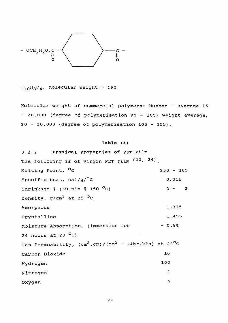
c -
o
C10H8°4' M°lecular weight = 192
Molecular weight of commercial polymers: Number - average 15
- 20,000 (degree of polymerisation 80 - 105) weight average,
20 - 30,000 (degree of polymerisation 105 - 155).
Table (4)
3.2.2 Physical Properties of PET Film
The following is of virgin PET film ( 22 ' 24 ).
Melting Point, °C 250 - 265
Specific heat, cal/g/°C 0.315
Shrinkage % (30 min @ 150 °C) 2 - 3
Density, g/cm3 at 25 °C
Amorphous 1.335
Crystalline 1.455
Moisture Absorption, (immersion for - 0.8%
24 hours at 23 °C)
Gas Permeability, (cm3 .cm)/(cm2 - 24hr.kPa) at 23°C
Carbon Dioxide 16
Hydrogen 100
Nitrogen 1
Oxygen 6
22

3.2.3 Chemical Properties
Dissolved by < 22 ' 23 >
1. Phenols (m - cresol, 0 - chlorophenol) and phenol/
chlorinated hydrocarbon mixtures (1/3 vol/vol).
2. Phenol/tetrachloroethane.
3. Acetonylacetone.
4. Dichloroacetic acid.
5. Concentrated sulphuric acid (with decomposition).
6. Hot benzyl alcohol.
7. Benzyl acetate.
Relatively unaffected by ( 22 ' 23 )
1. Hydrocarbons, esters and dry cleaning solvents.
2. Formic acetic, phosphoric and hydrofluoric acids.
3. Resistance to bleaching solutions.
4. Reducing agents and mild alkalis (e.g. Na 2 CO 3 ).
5. Moderate exposure to mineral acids.
Decomposed by
1. Hot alcoholic alkalis.
2. Hot aqueous alkalis (e.g. dil NaOH, particularly in the
presence of quaternary ammonium compounds).
3. Hot amines.
4. Mineral acids cause loss of strength, dependent on
concentration and on time and temperature of exposure e.g.
tensile strength falls to 50% after 50 hours at 100°C in 7.5%
HC1, 16% HN03 or 45% in H2 S04 .
23
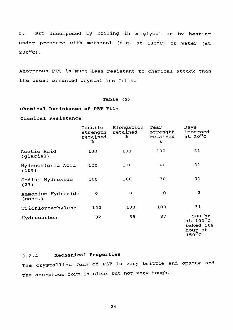
5. PET decomposed by boiling in a glycol or by heating
under pressure with methanol (e.g. at 180°C) or water (at
200°C).
Amorphous PET is much less resistant to chemical attack than
the usual oriented crystalline films.
Table (5)
Chemical Resistance of PET Film
Chemical Resistance
Tensile Elongation Tearstrength retained strengthretained % retained
Acetic Acid 100 (glacial)
Hydrochloric Acid 100 (10%)
Sodium Hydroxide 100 (2%)
Ammonium Hydroxide 0 (cone.)
Trichloroethylene 100
Hydrocarbon 92
100
100
100
100
88
100
100
70
100
87
Days immersed at 20°C
31
31
31
31
500 hr at 100°C baked 168 hour at 150°C
3.2.4 Mechanical Properties
The crystalline form of PET is very brittle and opaque and
the amorphous form is clear but not very tough.
24

Generally, the tendering process is preferred for biaxially
orienting polyethylene terephthalate ( 22 ' 23 ) for base films
due to the following < 23 ' 24 ' 25) :-
1. Highly resistant to most organic and mineral acids.
2. No plasticisers and very low moisture retention (less
than 0.5% at room temperature and 50% relative humidity).
3. High strength, toughness and durability, excellent flex
life.
4. Large number of specific modifications available.
5. Excellent electrical properties.
Table (6)
Typical Properties of PET Film
Elastic Modulus (Young's) (-MN/m2 ) 4400
Tensile Strength (MN/m2 ) 124
% Elongation 70
I.V. ml/g 0.9
25
CHAPTER FOUR
Experimental Work
4.1 Removal of Silver and Silver analysis
4.2 X-ray Base Plate
4.3 Determination of Papers and Adhesive Tapes
4.4 Water Absorption
4.5 Removal of PVDC Coating
4.6 Determination of PVDC
4.7 Determination of I.V.
4.8 Tensile Strength and Elongation
26
4.1 Removal of Silver and Determination of Silver Content
Procedure
The shredded sample of film was leached with an alkaline
oxidising solution of sodium cyanide.
Approximately 60 to 80g of sample material was weighed within
± O.Olg and transferred to a 1 litre beaker (tall size) which
was pre-weighed.
Leaching solution (800 ml) was then added. The composition
of the leaching solution was ( 2 °) :-
NaOH 50 g
NaCN 100 g
Meta nitrobenzenesulfonic acid 20 g
Deionised water 5 litres
The solution was stirred with a glass rod in order to wet the
small pieces of film. The sample was leached for two hours
with stirring.
The solution was filtered through No. 1 Whatman filter paper
of 9 cm diameter into a 1 litre volumetric flask.
Using a PU9100 Atomic Absorption Spectrophotometer with the
following working conditions:-
Single element 1 amp current 3 ma
Fuel Acetylene
Flame stoichiometry Oxidising
27
Wavelength 338.3 nm
Spectral band pass 0.2 nm
Range 3-12 ppm
Support Air
Safety Considerations( 27 Decomposition of the cyanide solutions after the test *•
was carried out.
28

Results
Type of film
Large Exposure
Low Exposure
Large Exposure
Low Exposure
Large Exposure
Low Exposure
Large Exposure
Low Exposure
Green Film
Large Exposure
Low Exposure
Green Film
Table (7)
Year Weight
1950
1950
1960
1960
1970
1970
1980
1980
1980
1985
1985
1985
(g)80.
80.
50.
50.
60.
100.
70.
30.
50.
80.
60.
50.
Silver
Content
Perce
of Si
(g)00
00
00
00
00
00
00
00
00
00
00
00
0
0
0
0
0
2
0
0
1
0
0
1
.9600
.5680
. 6000
.9950
. 6480
. 0900
.4620
.4350
. 1000
.5040
.7680
.0500
1
1
1
1
1
2
0
1
2
0
1
2
.20
.96
.20
.99
. 08
.09
.66
.45
. 20
.63
.28
. 10
See samples in Appendix A page 108
29

Figure No. (1)
Graph showing the % of Silver vs Year of Manufacturing
%of Silver
Large exposure fil
Low exposure film
Green film
1950 1960 1970 1980 1990
Year of manufacturing
2000
30

4 . 2 X-ray Film Base Plate
Poly (ethylene terephthalate) PET and cellulose Triacetate
CTA are two types of plastics used in the manufacturing of X-
ray base plates, which they are investigated by the following
methods.
4.2.1 Density
A number of X-ray plates were taken from different periods,
and after de-silvering them using sodium hypochlorite, and
the surface of the film was delaminated with an organic
solvent namely tetrahydrofuran. The plates were dried and
weighed and then the density was determined.
Results
Number of
Table (8)
Weight of Average weight Density Period
X-ray platestaken
53
66
93
100
Plates (g)
1706
2165
2827
2960
per Plates (g)
32 .2
32 .8
30.4
29. 6
kg/m
2810
2860
2650
2490
1950-1959
1960-1969
1970-1979
1980-1985
4.2.2 Infra-red Reflectance (ATR)
The infra-red analysis was of a quantitative nature and
involved standard techniques such as the preparation of film
discs in order to obtain spectra of the samples under
analysis. Once obtained, these spectra were compared with
31

reference spectra prepared in a similar manner to the
samples.
The results are shown in Figure 2 and Figure 3.
32

U)
96J 94-
92-
90H
•H e co S 86
-u H
82- J
80 78
75.6
.
Figure No(2)
Infr
a-re
d spectra
for
PET
Refe
renc
e sample
4000
.0
Cle
an
sam
ple
o
f PE
T X
-ray
fi
lm
3500
3000
2500
2000
.0
Wav
e N
umbe
r1800
16
00
1400
12
00
1000
80
060
0
Cm-1
I I
400.
0

JS rt> O.
•o0)o
03
H- OQC*sresa oOJ
3-4

4 . 3 Determination of Papers and Adhesive Tapes
A sample of X-ray film was taken and weighed before
separating the papers and tapes. The separation was carried
out physically by hand and each component was weighed
separately.
Results
Run
1
2
3
4
5
Weight of
Sample (kg)
30
50
63
65
85
Table (9)
Weight of Wei
X-ray film Tap
(kg)
27.50 C
45.60 C
57.60 3
57.50 C
78.00 :
Calculations
Run
1
2
3
4
5
% X-ray film
91.7
91.2
91.4
91.5
91.7
Table (10)
% Adhesive tape
1.5
1.5
1.6
1.5
1.3
0.45
0.75
1.00
0.97
1.14
Weight of
Paper
(kg)
2.05
3.65
4.40
4.53
5.86
% Paper
6.8
7.3
7.0
7.0
6.9
35

4.4 Water Absorption
This experiment covers the determination of the relative rate
of absorption of water by the X-ray base plates and their
pellets when immersed in water or exposed to the atmosphere
at normal conditions.
This test has two significant functions:-
A As a guide to the proportion of water absorbed by Poly
(ethylene terephthalate) and consequently, the relationship
between moisture content and its mechanical properties.
B As a control test on the uniformity of the product.
Theory
The rate of water absorption may be widely different through
each edge and surface. It may be slightly greater through
cut edges than through pelletised surfaces. Consequently,
attempts to correlate water absorption with the surface area
must generally be limited to closely related materials.
For materials of widely varying density, the relation between
water absorption values and a volume as well as a weight
basis may need to be considered.
Calculation
Percentage increase in weight
= Wet Weiaht - Conditioning Weight) x 100
Conditioning Weight
36
Percentage of soluble matter lost
= Conditioning Weight - Reconditioning Weight) x 100
Conditioning Weight
Reconditioning Weight: This is the dry weight of the
specimen after immersion, for the same temperature and time
as used in the original drying period of the conditioning.
The percentage of water absorbed = percentage of increase and
percentage of matter lost. If the weight of reconditioning
exceeds the conditioned weight, then the percentage of
soluble matter lost is considered to be nil
Preparation of the Sample
The test sample is placed in a dry air swept oven (less than
3% relative humidity) at ± 39.5°C for 24 hours. Then the
sample was removed from the oven and cooled in a desiccator
to room temperature and immediately weighed to the nearest O.O01 g ( 2? ) .
Three specimens were taken:
Specimen No. SI
Represents film before the process, i.e. still containing the
silver emulsion coating.
Specimen No. 82
Represents film after removing the silver layer and immersed
in cyclohexanone at room temperature for 15 minutes or longer
37

to dissolve the coating entirely from the PET, and then it
was rinsed in ethyl acetate and water.
Specimen No. S3
Represents clean pelletised X-ray film after it has been
de-silvered and delaminated.
All specimens should be oil and wax free.
Procedure
4.4.1 Immersion in Water
The dry samples were fully immersed in a container of
deionised water at a temperature maintained at 23 ± 1°C for 2
hour and 24 hour respectively. The samples were then removed
from the warm water, one at a time, and cooled in distilled
water maintained at 20°C. After 15 minutes the samples were
removed from the cold water and the surface was wiped free of
the water with a dry cloth and weighed to the nearest
0.0001 g.
4.4.2 Moisture Permeability
The dried sample was placed over the top of an aluminium cap
and left in the storage area (normal conditions, with
temperature about 15 °C) for l day, 7 days, 30 days, 90 days
and 180 days exposed to the air. The samples were then
weighed to the nearest 0.0001 g.
in the specimens (SI, S2, S3), the samples were then placed
38

in a dry (less than 3% relative humidity) air swept oven at
39.5°C for 24 hours, then the sample was cooled, in a
desiccator to room temperature and weighed to the nearest
0.0001 g.
The above procedure was repeated three times and an average
result was taken for each sample.
39

Results
Water
Immersion
2 Hours
Immersion
Table
(11)
Specimen
Wet
Conditioning
Reconditioning
% of Increase
Number
Weight (g)
Weight (g)
Weight (g)
in W
eight
% of Soluble
% of W
ater
Matter L
ost
Absorbed
SI S2 S3
20.3241
20.0840
20.1400
20.3239
20.0820
20.1398
20.3420
20.1111
20.1461
0.00
0.01
0.00
0.00
0.00
0.00
0.00
0.01
0.00
24 Hours
Immersion
Specimen
Wet
Number
Weight (g)
Table
(12)
Conditioning
Reconditioning
% of Increase
Weight (g)
Weight (g)
in W
eight
% of S
oluble
% of W
ater
Matter L
ost
Absorbed
SI S2 S3
20.1000
19.8191
19.9841
20.0199
19.7278
19.9797
20.0336
19.7238
20.0011
0.4001
0.4528
0.0221
0.00
0.203
0.00
0.4001
0.4831
0.0221

Table
(13)
Moisture P
ermeability
Specimen
Period o
f Moisture
Conditioning
Reconditioning
% of Increase
% of M
atter
Number
Exposure
Weight
Weight (g)
Weight (g)
in W
eight
Lost
(Days)
(g)
% of W
ater
Absorbed
SI S2 S3 SI S2 S3 SI S2 S3
1 1 1 7 7 7 30 30 30
180.
190.
195.
179.
165.
182.
178.
166.
159.
3014
1391
0013
0301
1952
6636
1122
3320
5631
180.3012
190.1391
195.0012
179.0068
164.6986
182.6634
177. 9376
165.4222
159.5117
180
190
195
179
164
182
177
165
159
.3023
.3641
.0199
.0069
.6980
.6634
.9400
.4232
.5090
0. 0. 0. 0. 0. 0. 0. 0. 0.
0001
0000
0000
0130
3015
0001
0981
5500
0322
0 0 0 0, 0. 0. 0. 0. 0.
.0000
.0000
.0000
.0000
,0004
,0000
0000
0000
0018
0.0001
0.0000
0.0000
0.0130
0.3019
0.0001
0.0981
0.5500
0.0340
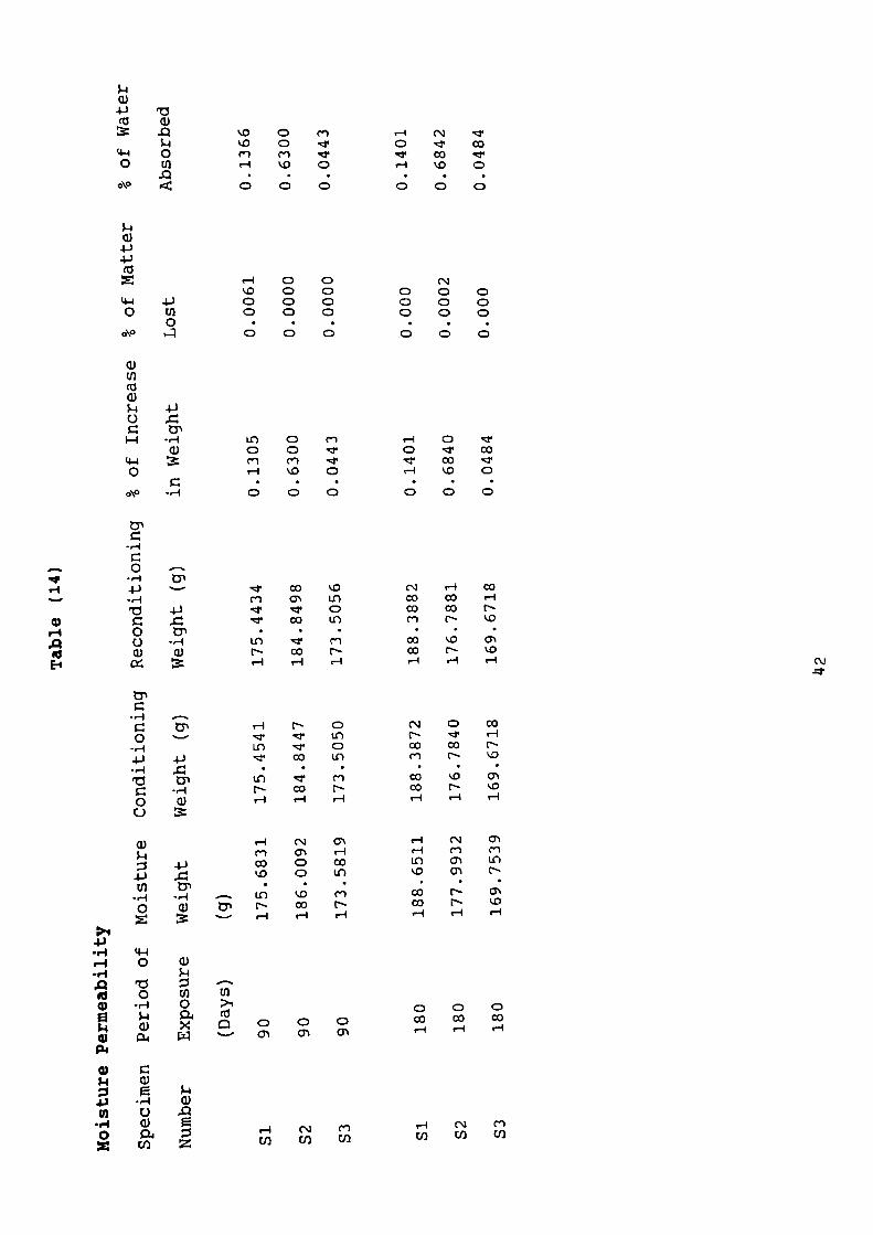
Tabl
e (14)
Mois
ture
Per
meab
ilit
ySpecimen
Peri
od o
f Moisture
Co
ndit
ioni
ng
Reco
ndit
ioni
ng
% of In
crea
se
% of M
atte
r
Number
Expo
sure
Weight
Weight
(g)
Weight
(g)
in W
eigh
t Lo
st
(Days)
(g)
% of W
ater
Absorbed
SI S2 S3 SI S2 S3
90 90 90 180
180
180
175.
6831
186.0092
173.5819
188.6511
177.99
32
169.75
39
175.4541
184.8447
173.5050
188.3872
176.7840
169.6718
175.4434
184.8498
173.5056
188.3882
176.7881
169.6718
0.1305
0.63
00
0.04
43
0.14
01
0.68
40
0.0484
0.00
61
0.00
00
0.00
00
0.00
0
0.0002
0.00
0
0.1366
0.6300
0.04
43
0.14
01
0.68
42
0.04
84

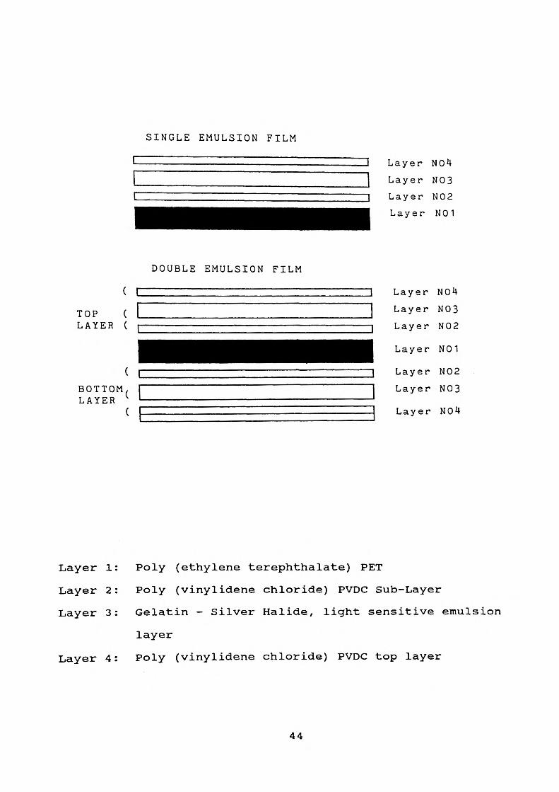
4.5 Removal of Poly (vinylidene chloride) Coating
During the manufacturing of X-ray film, PVDC (Saran) is
applied before the base film is wound into rolls ( 27 ' 29 ) ,
this process produced a great deal of unrecyclable PET waste.
So the coating must be removed without damaging the PET.
Economic and chemical considerations require that there be
little or no decomposition of the solvent media, or
significant reaction of the solvent media with the X-ray film
raw material. This is because it is an economic necessity
that the solvent be capable of being recovered in fully
useful form for recycling.
43
SINGLE EMULSION FILM
Layer NOU
Layer N03
Layer N02
Layer N01
( C
TOP ( L LAYER ( r
BOTTOM LAYER
DOUBLE EMULSION FILM
Layer NOU
Layer N03
Layer N02
Layer N01
Layer N02
Layer N03
J Layer NOU
Layer 1: Poly (ethylene terephthalate) PET
Layer 2: Poly (vinylidene chloride) PVDC Sub-Layer
Layer 3: Gelatin - Silver Halide, light sensitive emulsion
layer
Layer 4: Poly (vinylidene chloride) PVDC top layer
44

The sub-layer of PVDC (Saran) is applied to improve the
adhesion of the light sensitive emulsion to the film base PET
and it is chemically inert towards it.
The top layer of PVDC is added for moisture and gas
protection due to its low permeability to a wide range of
gases and vapours and it is also hydrophobic.
There are two ways of decoating Saran from PET X-ray film
base.
1. Solution Method
2. Delamination/Segregation Method
4.5.1 Solution
Poly (vinylidene chloride) can be dissolved away from the PETf 1 Q \
substrate using a number of solvents \-l- y ' .
Cyclohexanone and chlorobenzene were tried to remove the PVDC
from X-ray plates.
Procedure
Samples of 1 kg of de-silvered X-ray film were shredded in
two ways:-
(i) knife shredding
(ii) hammer shredding
The size of the particles was 5 cm. The samples were then
45

placed in the above solvents and the contents were stirred
continuously for 15 minutes, to ensure complete contact of
solvents with the pieces of X-ray film.
Results
Table 15 shows the effect of different cutting methods on the
decoating.
Specimen Solvent Used
1 Cyclohexanone
2 Cyclohexanone
3 Chlorobenzene
4 Chlorobenzene
Table (15)
Knife Cut
Unsatisfactory
Unsatisfactory
Hammer Cut
Satisfactory
Satisfactory
4.5.2 Delamination/Segregation
In this method the PVDC was removed in two steps, a
delamination/segregation process which was carried out in a
single unit operation.
The segregation step of PET from PVDC and other contaminants
such as paper, metals involves a flotation process, where the
PET sinks and the Saran and other contaminants float to the
top of the bath.
46
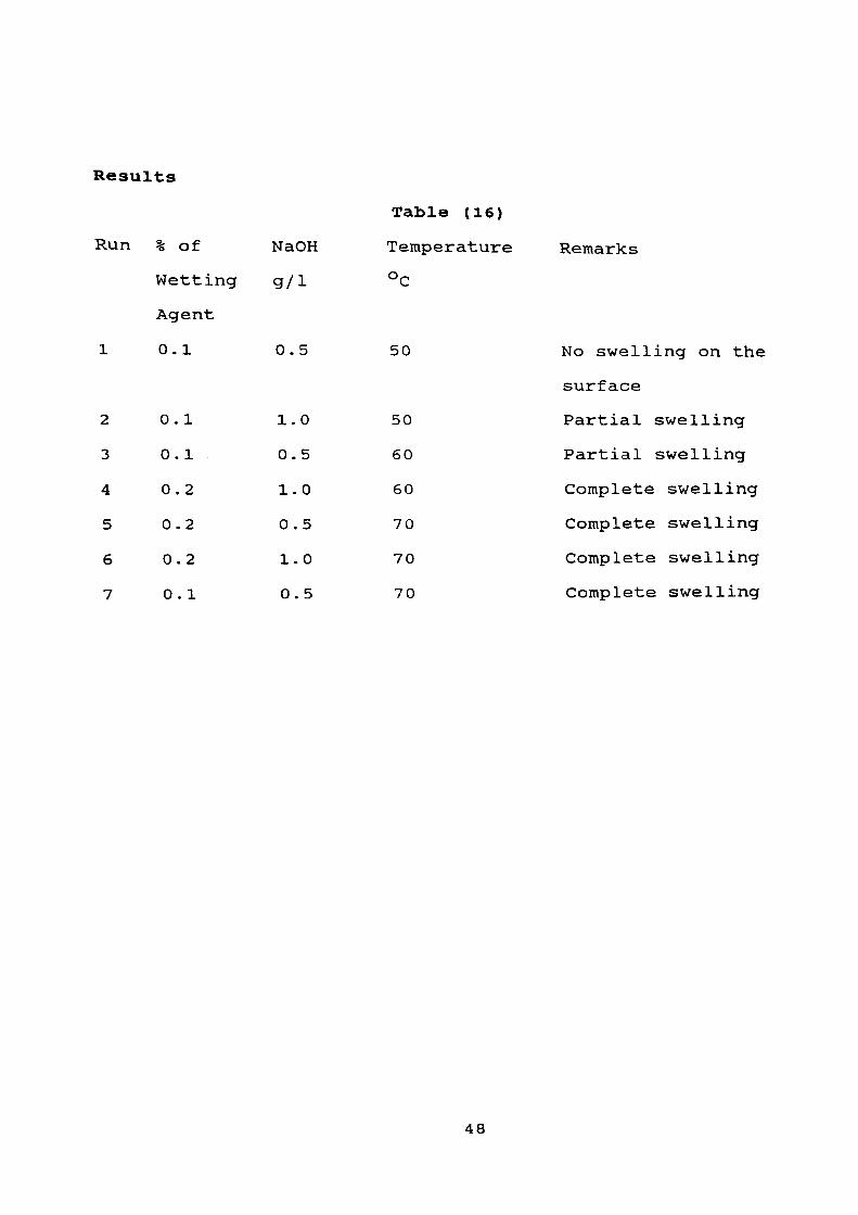
Procedure
De-silvered X-ray film was shredded into small pieces using a
hammer mill. The film was treated with a hot solution of
sodium hydroxide and wetting agent for 2 hours with
continuous stirring.
The material was then treated with another solution of 40%
water - sodium bromide ( 28 ) at a temperature less than 15°C
with air bubbles introduced from the bottom through spargers.
This process was continued for 2 hours to produce PVDC and
adhesive paper floating on the top, while PET and metals sank
to the bottom.
Safety Considerations
1. The sodium hydroxide was used in small quantities (0.5 -
1.0 g/1) so that little effluent pollution problems were
anticipated.
2. The wetting agent used was a polyglycol ether of a fatty
alcohol (known as MIRAVON B79R - RTZ chemicals) with flash
point of 100°C, low toxicity of LD50 above 2000 mg/kg and
non-corrosive.
47
Results
Run % of NaOH
Wetting g/1
Agent
1 0.1 0.5
Table (16)
Temperature
50
2
3
4
5
6
7
0.
0.
0.
0.
0.
0.
1
1
2
2
2
1
1
0
1
0
1
0
.0
. 5
.0
.5
.0
.5
50
60
60
70
70
70
Remarks
No swelling on the
surface
Partial swelling
Partial swelling
Complete swelling
Complete swelling
Complete swelling
Complete swelling
48

4 . 6 Determination of Poly (vinylidene chloride)
PVDC or Saran can be determined in a sample of X-ray film by:
A Staining with triethylene tetramine which colours the
residual PVDC brown.
B Melting the chip in an aluminium dish at 300°C for 15
minutes.
C Carrying out chlorine analysis.
Method 'A' was used on the flakes to give a quick indication
of the contamination of the PET with PVDC.
Method 'B 1 was used before the extrusion process of PET.
Method 'C' was used to determine the PVDC in the PET sample.
Theory
The sodium metal reacts with the chlorine atoms in the PVDC
to form sodium chloride.
The percentage of chlorine in the dry silver chloride was
24.74% and PVDC contains 73.14% chlorine ( 24 ).
49

Procedure
A sample of dry X-ray PET film was weighed and placed in a
test tube with a small piece of sodium metal using a pair of
tweezers and dry knife to cut the sodium. The tube was
heated carefully in a gas flame with the open end of the tube
pointed away, from the face, the heat was continued until the
metal melted, then the tube was quenched rapidly by
submerging the hot end in a strong beaker containing
approximately 10 ml of distilled water (ordinary water is so
polluted, that it will make errors in the test results) .
Obviously, the tube was shattered in the water and the
products of the heating dissolved in the water.
The liquid was stirred carefully with a long glass rod to
make sure that all of the metal was reacted. Then the liquid
was filtered through unbleached paper to remove the solids.
Using HACK DR/2000 Spectrophotometer with the following
working conditions:
Wavelength
Time
Solvents (mixture)
530 nm
3 minutes
Perchloric acid and Mercuric
thiocyanate
50

Results
A Unexposed X-ray film (green film)
Table (17)
Run
1
2
3
4
5
B
Run
1
2
3
4
5
Weight of
Sample (g)
1.0971
1. 3673
1.8007
1.060
1. 0792
De-silvered X-ray
Weight of
Sample (g)
1.5320
1. 3221
1. 3330
1.0786
1.6707
% Of
C1 2
2.01
2.09
2 .03
2.02
1.98
Film
Table
% of
ci 2
1. 10
0.77
1.00
0.97
1.03
% of
PVDC
2.75
2 .85
2 .78
2 .76
2.48
(18)
% Of
PVDC
1. 51
1.05
1.37
1.33
1.41
Weight
PVDC (PPM)
30216
38966
50041
27755
26798
Weight
PVDC (PPM)
23106
13946
18184
14355
23517
51

C De-silvered and Delaminated X-ray Film
Table (19)
Run Weight of % of % of Weight
Sample (g) C1 2 PVDC PVDC (PPM)
1 2.0030 000
2 4.9836 000
3 4.9830 000
4.7 Determination of Intrinsic Viscosity (I.V)
The IUPAC terra for the I.V. is the Limiting Viscosity Number.
It is the simplest diagnostic tool for estimating the
molecular weight of a plastic.
The method consists of simply measuring the flow time through
a capillary viscometer of a dilute solution of a polymer and
of the pure solvent at specified conditions of temperature
and concentration.
There are four flow types ( 30 '
1. Newtonian: Oils, water, aqueous solutions of
low - molecular weight substances.
2. Pseudo-plastic: Solutions of high polymer chain
molecules.
52

3. Plastic: Suspensions and emulsions with
solvate envelopes, the solvated
particles of the disperse phase
touching each other.
4. Dilatant: (Turbulent) dispersions without
solvate envelopes the particles
almost touching each other, i.e. a
tightly packed system.
Theory
The relative viscosity is defined as the quotient of the
viscosity of the solution NS and the viscosity of the solvent
Nso
Nr = Ns/Nso
Another measure of the increase in viscosity by a high
molecular weight solute is the specific viscosity.
Nsp = Nr - 1
Then the limiting viscosity is one when either Ngp/C or
(LnN )/C is extrapolated to zero concentration.
j.V. = [N] = Lim Msp = Lim Ln_Nr
C ->• O C C -* O C
C is the polymer concentration g/ml.
53

Since the relative viscosity is dimensionless, the units for
[N] are those of reciprocal concentration. The (IUPAC)
concentration unit is g/ml.
I.V. Units are ml/g
Procedure
The method ( 32 ) covers the determination of the dilute
solution - viscosity of polymers.
A sample X-ray film (PET) was weighed and dissolved in a
solution of o - chlorophenol and transferred into a nitrogen
purged 100 ml volumetric flask (the flask was purged to
prevent the oxidation of the sample) .
The sample was stirred continuously until the PET dissolved
completely.
The volumetric flasks containing the solutions and the pure o
- chlorophenol solvent were placed in a constant temperature
water bath at 30 °C. o - chlorophenol was added to each
flask to make up the total volume in each flask to 100 ml and
the solution was mixed well.
When the temperature equilibrium has been reached after
approximately 30 minutes, the liquid level in the viscometer
was brought above the upper graduation mark by means of
slight nitrogen pressure applied to the arm opposite the
54

capillary.
The timer was started exactly as the meniscus passes the
upper graduation mark and was stopped as it passed the lower
mark.
This procedure was repeated for each sample and for the pure
solvent.
The results were plotted in a computer using Technicurve
program.
Safety Considerations
o - chlorophenol C1C 6H4OH (boiling point 175 °C) , is toxic
and appropriate measures were taken to avoid breathing its
vapours, or contact of the liquid with skin or on eyes.
55

Moist X-ray Film (flake form)
The flake sample was left in storage conditions of ± 20°C
for 60 days before the test was carried out.
Table (20)
Run
1
2
3
4
5
6
C
(g/lOOml)
0.
0.
0.
0.
0.
0.
23
33
41
49
60
74
Nr
1.
1.
1.
1.
1.
1.
1473
2146
2584
3380
4200
5327
Nr-
0.
0.
0.
0.
0.
0.
- 1
C
64
65
63
69
70
72
Linear Regression Results (Figure 4)
Slope 0.177
N - 1 °' 589L
C
Correlation coefficient 0.894
Standard error 0.018
56

Dry X-ray Film (flake form)
The flake sample was dried in an oven at a temperature of ±
50°C for 24 hours prior to the test.
Table (21)
Run
1
2
3
4
5
6
C Nr
(g/lOOml)
0.
0.
0.
0.
0.
0.
14
24
40
58
65
75
1.
1.
1.
1.
1.
1.
1037
788
3020
4292
4876
5624
— r ———
C
0
0
0
0
0
0
.74
.74
.75
.74
.75
.75
Linear Regression Results (Figure 4)
Slope 0.015
Nr - 1 0-738
C
Correlation coefficient 0.636
Standard error 0.005
57

Figure Number (4)
Graph to determine the I.V. of PET flake
(Np -1)/c
1.0
.9
.8
.7
.6
.5
.4
.3
.2
.1
0.0 0
A Table(20)
.1 .3 .4 .5 .6 C g/100ml
.7 .8 .9 1.0
58

Moist X-ray Film (pellet form)
The pellet sample was left in ordinary storage conditions of
± 20°C for 60 days prior to the test.
Run C
Table (22)
Nr K:
(g/lOOml)
1
2
3
4
5
0.
0.
0.
0.
0.
15
32
39
63
72
1.
1.
1.
1.
0.
0656
1473
0209
3591
4247
0
0
0
0
0
r - 1
C
.44
.46
.51
. 57
.59
Linear Regression Results (Figure 5)
Slope 0.279
M. - 1 0-391—— £-—————————
C
Correlation coefficient 0.983
Standard error 0.014
59
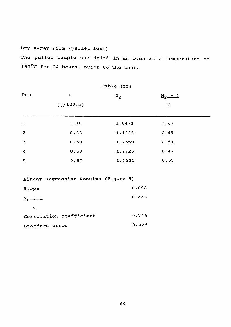
Dry X-ray Film (pellet form)
The pellet sample was dried in an oven at a temperature of
150°C for 24 hours, prior to the test.
Table (23)
Run C N Nj_ j_ (g/lOOml)
1
2
3
4
5
0
0
0
0
0
. 10
.25
.50
. 58
. 67
1.
1.
1.
1.
1.
0471
1225
2550
2725
3552
0.
0.
0.
0.
0.
- 1
C
47
49
51
47
53
Linear Regression Results (Figure 5)
Slope 0.098
- 1 0.448I,"
C
Correlation coefficient 0.716
Standard error 0.026
60

Figure Number (5)
Graph to determine the I.V. of PET pellet
N--1 ) /C r
1.0
.9
.8
.7
.6
.5
.4
.3
.2
.1
0.0 0
Table(22)
Table(23)
.1 .2 .4 .5 .6
C g/100 ml
.7 .8 .9 1.0
61

50% X-ray Film + 50% Virgin PET Blend
Table (24)
Run C Nr Nr.
(g/lOOml)
1
2
3
4
5
0.
0.
0.
0.
0.
14
30
80
52
70
l.
l.
1.
1.
l.
1162
2625
7000
4992
6825
0.
0.
0.
0.
0.
- 1
C
830
875
875
960
975
Linear Regression Results (Figure 6)
Slope 0.130
N_ - 1 0.839__£-_—_
C
Correlation coefficient 0.576
Standard error 0.058
62

60% X-ray Film + 40% Virgin PET Blend
Run
1
2
3
4
5
Table (25)
C N N_ - 1±. 'I. ————————
(g/lOOml) c
0.25 1.2000 0.80
0.30 1.2430 0.81
0.45 1.3735 0.83
0.55 1.5451 0.82
0.74 1.6438 0.87
Linear Regression Results (Figure 6)
Slope 0.126
Nr - 1 0.768
C
Correlation coefficient 0.925
Standard error 0.012
63

Figure Number (6)
Graph to determine the I.v. of PET Blend
(Nr -1
1.0
.9
.8
.7
.6
.5
.4
.3
.2
.1
0.0 0
Table(24) a
Table(25)
.1 .2 .3 .4 .5 .6 .7 .8C g/100 ml
.9- 1.0
64

4.8 Tensile strength and Elongation
Plastics are being increasingly recommended for purposes
which involve the withstanding of stresses.
The most important properties are the tensile strength and
elongation. To withstand rupture, by pulling apart, is a
factor of prime importance when a material is being
considered for use as a stress bearing member.
The property of some plastics, which frequently prevents
their use for the manufacture of strained members, is their
poor ductibility as shown by their comparatively small
elongation at break.
Theory
1. Tensile Strength at Break (Nominal)
This can be represented by dividing the load at break by the
cross sectional area.
Tensile strength at rupture
= Load at rupture. Pr
Cross Sectional Area, A
ar = Pr
65

2 . Percentaae Elongation at Break
This can be represented by dividing the elongation at the
moment of rupture of the specimen by initial gauge length of
the specimen and multiplying by 100.
Percentage elongation, e% = elongation at rupture x 100
original length
e% = gauge length - original length x 100
original length
e% = L1 - L x 100
3 . Modulus of Elasticity (Young's Modulus)
It is defined by Hooke's law as the ratio of direct stress a
to strain produced £ and is called Young's Modulus or the
Modulus of Elasticity (E) .
E = a t
For bar of uniform cross section A, length 1, and p is the
load applied, the stretch or elongation produced X
E = pi
AX
66

Procedure
A load range was selected such that specimen failure occurs
within its upper two thirds. A few runs were tried to select
a proper combination of load range and specimen width < 33 ) .
The grip was calibrated and balanced to zero and the total
length between the grip marks was recorded.
A specimen of known rectangular cross-sectional area was
placed between the grips of the testing machine. Care was
taken in aligning the long axis of the specimen with the
imaginary line joining the points of attachment of the grips
to the machine.
Then the grips were tightened evenly and firmly to the degree
necessary to minimise slipping of the specimen during the
test, then the machine readings were recorded.
67

Results
Table
(26)
Run
Specimen
Width
(mm)
Specimen
Length (mm)
Specimen
Area (mm2
)
Elongation
%
Tensile
Strength
N/mm
2
Modulus
of
Elasticity
N/mm
2
A B C D E F G H
2.9
2
2.9
1
2.8
9
2.8
9
2.9
0
2.9
2
2.8
9
2.8
9
10.2
0
10.1
2
10.2
1
10.1
4
10.1
1
10.1
1
10.1
3
10.0
8
29.7
8
29.4
5
29.5
1
29.4
1
29.3
2
29.5
2
29.2
8
29.1
3
0.6
7
0.6
7
0.4
8
0.8
7
0.7
7
0.6
3
0.5
8
0.7
7
0.7
7
0.7
8
1.5
7
0.9
3
1.1
9
0.5
5
1.1
4
1.1
4
232.7
9
252.2
5
227.3
9
228.1
7
253.3
7
220.1
8
253.7
5
238.0
0
68

The table number 2 1? shows the blending results of ^PET from
X-ray film plus Virgin PET manufactured by i.e.I.,
commercially known as Melinar, which has the following
specifications:-
Tensile strength =
Density =
I.V.
% of water absorption =
3.68 N/mm2
1410 kg/m3 at 25 °C
0.92
0.60%
Specimen
Table (27)
Percentage Tensile
Elongation Strength
N/mm2
1
2
3
Blending
Temperature
for 2 hours
380
360
490
1.50
1.55
1. 53
270
275
280
Specimen land
Blens of 60:40% film:virgin PET
Specimen 3
Blend of 50:50% fllm:virgin PET
69
CHAPTER FIVE
Discussion of Results and Conclusions
The experimental results in Chapter 4, show that the silver
content in used X-ray film and unexposed X-ray film depends
upon the age of the X-ray and the intensity of light
exposure. Figure No. (1) year of manufacturing of X-ray vs
the percentage of silver in the film, shows that the silver
content in X-ray film manufactured in the 80's is almost half
of that manufactured in the 50's. Also from the results in
Table 8 that the X-ray plates manufactured in the 1950's and
60's are not the same density as those manufactured in the
70's and 80's. This is because the material used in the 50's
and 60's was cellulose triacetate (CTA), and the material
used in the 70's and 80's is poly (ethylene terephthalate)
PET, as it was confirmed by the Infra-red Reflectance (ATR) ,
Figure Nos. (2) and (3) .
Table 10 shows that the content of adhesive tape is 1.5% and
the loose paper is 7%.
Experiments in Section 4.4 show that PET is hydrophobic i.e.
it is difficult to wet it with water and the results in Table
11 show that the moisture content of PET increases with time
of exposure to the atmosphere. The percentage of water
absorbed depends to some extent on the shape of the test
sample, as shown in Tables 11-13.
70

The moisture content of the PET film is related to the
mechanical strength and appearance. The effect upon these
properties, of change in moisture content, depends largely on
the type of exposure (immersion in water or exposure to high
humidity) and duration of the exposure. As it was expected
the coated film absorbed much less water than de-silvered and
delaminated samples, because the former is coated with silver
emulsion layers which act as a barrier. So before the
pelletisation process, the PET flakes were dried in a
dehumidifying drier, capable of circulating a continuous
supply of warm air to the pellets at the recommended
controlled temperature of 200°C. Blended X-ray pellets with
virgin PET also required drying. Care was taken during the
drying operations not to exceed a temperature of 200°C
because the PET melts at 220°C.
Moisture is a vital factor, and the presence of it in the PET
will have a negative influence on the surface appearance,
strength and physical properties as shown from the results in
Section 4.g and 4.7. The viscosity of PET was affected
drastically by the moisture content of the sample.
The results of I.V. tests were initially affected by the deep
blue colouration. To obtain a clear solution, the sample of
X-ray film was dissolved in a solution of o-chlorophenol at
room temperature, while the pellet samples had to be warmed
up to 80°C / for three days. Moisture content studies by
drying the film flakes and pellets to constant weight, shows
71

that the film flakes absorbed 0.55% water and the pellets
absorbed 0.0348% water. For the period of 30 days exposure,
Table 14, this is due to the larger surface area of the
flakes exposed to the atmosphere dried under the same
conditions, and the following I.V. results were obtained.
Table (28)
PET Film PET Pellets
Dry 0.738 0.448
Moist 0.589 0.391
% increase 20.19% 12.72%
after drying
The results in Table 28 confirm that the moisture content
depresses the intrinsic viscosity of the PET in both PET film
and PET pellets. The possible error that could have happened
in these results is if the film samples were not
representative of the bulk stock.
In addition, extrusion of moist PET will give substantial
breakdown of the PET, as it can be seen from the
palletisation of PET X-ray flakes that the I.V. decreased
from 0.738 to 0.448. This may be caused when the PET melted
to form pellets, air reacts rapidly with it and as a result
the air gets trapped in the pellets. This may also explain
the reduction in the I.V. of the pellet form. The I.V. of
0.738 of dried PET is a satisfactory result, therefore
venturing into the costly build up of I.V. by the Zimmer
72

reactors may not be required (Zimmer reactors are used to
increase the i.v. by heating the polymer to 200°C and cool it
under nitrogen blanket).
PVDC can be dissolved away from the PET film flake substrate
using a number of solvents, which were proven very
satisfactory as shown in Table 15, but this method suffers
from toxicity or flammability problems.
Cyclohexanone, chlorobenzene, and 1.4 dioxane all suffer from
hazard problems. A more fundamental problem is that
spreading of solutions onto previously uncoated surfaces can
leave the PET flakes with PVDC coated in areas not originally
coated.
A process using chlorinated solvents does suffer from major
problems of absorption of the chloro-carbons into the PET
flakes, although it is acceptable for water removal prior to
injection moulding. It may be less acceptable due to the
effect of chloro-fluro Carbon on the environment. This could
be construed as an unacceptable method for solving another
environmental problem. It is also shown that the critical
steps in delamination and removal of PVDC and adhesive papers
is to ensure that the feed X-ray film is cut in a manner so
that the chips have a creased cut shape, so that they do not
seal each other.
Table 15 shows that hammer cut is more effective than the
73

knife cut. Table 16 shows the economic condition, for the
penetration of the solution to take place at the interface
between the solution and the PET substrate. When the
temperature is 60°C and sodium hydroxide concentration is 1.0
g/1 then coatings loosen and soften. The segregation of PET
was carried out by the flotation process in water media
containing a wetting agent at room temperature, with
continuous air agitation.
PVDC flakes and adhesive tapes float to the top while the PET
flakes, sink to the bottom. This action took place because
when a very small quantity of wetting agent was added to the
water, the surface tension of the water was reduced and the
PVDC changed from being hydrophobic to hydrophilic.
On the other hand, the drop in the temperature of the media
causes the PVDC layer to shrink and its shrinking rate is
different from that of the PET layer, and hence the
separation of the two polymers.
The segregation step may require a multi-stage approach as
the PET can act as an excellent filter bed for the removal of
PVDC and any other contaminants. The results of the PVDC
test shown in the Table 16, indicate that PVDC content in the
unexposed film was 2.7% and green film shows heavy
contamination due to the presence of PVDC and photographic
salts. After de-silvering the flakes, the result shows in
Table 17, that the PVDC content was reduced to nearly half
74

that of the green film and the remaining PVDC left on the
film must have come from the second layer. Table 19 shows
that no PVDC nor photographic salts were left after using the
process in (4.5). That means that the PET is suitable for
extrusion, but the mechanical test, confirmed that the PET
was unsuitable. The test results in Table '--- .. 26 showf
that the elongation percentage is 0.63 to 0.87 and tensile
strength 0.58 to 1.57 N/mm2 for the de-silvered/delaminated
X-ray film.
In this case the test shows that the tensile strength may be
sufficient, but the elongation percentage is very low, for
this material to be extruded.
For this reason the material was blended with the virgin PET
(Melinex). The results of the blending show in Table 25 that
a blend of 60% X-ray film and 40% of virgin PET produced an
IV of 0.768, and a blend of 50:50% produced an IV of 0.839.
Also the results in Table 21 show the elongation percentage
of 60:40% blend produced 360% while 50:50% blend Table 27
produced 490%. So in this way the material can be used and
recycled as marketable pellets.
The results of the following blends are not available as it
takes more time to be completed.
75
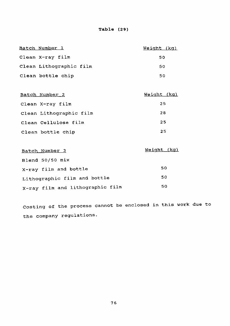
Table (29)
Batch Number 1
Clean X-ray film
Clean Lithographic film
Clean bottle chip
Weight (kg)
50
50
50
Batch Number 2
Clean X-ray film
Clean Lithographic film
Clean Cellulose film
Clean bottle chip
Weight (kg)
25
28
25
25
Batch Number 3
Blend 50/50 mix
X-ray film and bottle
Lithographic film and bottle
X-ray film and lithographic film
Weight (kg)
50
50
50
Costing of the process cannot be enclosed in this work due to
the company regulations.
76

CHAPTER SIX
Mass Balance and Heat. Requirements
6.1 Mass Balance Across the Plant
6.2 Heat Requirements
77

6.1 Mass Balance Across the Plant
The analytical results quoted in Tables 7, 9, 10 and 17 were
used as the basis for the calculations of mass balance (see
the flow sheet in Chapter 8) . The raw material consists of
the following compounds:
Table (30)
Compound % wt
Film 93
Loose paper 7
The film consists of the following compounds:
Compound % Wt
Silver 1.20
PVDC 2.00
Adhesive tape 1.50
Gelatin 0-30
PET 95.00
100.00
Basis 1000,000 kg starting raw material per year. Then the
input rate of raw material =417 kg/hr
See flow sheet Appendix B, page 110 .
78
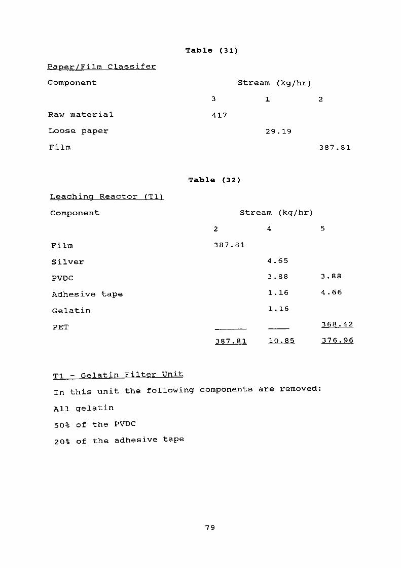
Table (31)
Paper/Film Classifer
Component
Raw material
Loose paper
Film
Stream (kg/hr)
312
417
29 .19
387.81
Table (32)
Leaching Reactor
Component
Film
Silver
PVDC
Adhesive tape
Gelatin
PET
Stream
2 4
387.81
4.
3.
1.
1.
387.81 10
(kg/hr)
65
88
16
16
.85
5
3.88
4.66
368.42
376.96
Tl - Gelatin Filter Unit
In this unit the following components are removed:
All gelatin
50% of the PVDC
20% of the adhesive tape
79

Table (33)
Component Stream (kg/hr)
467
Silver 4.55 4.55
PVDC 3.88 3.88
Adhesive tape 1.16 1.16
Gelatin 1.16 ___ 1.16
10.85 4.65 6.20
Table (34)
Silver Recovery Unit
All silver recovered in this unit
Stream 8 4.65 kg/hr
Table (35)
Hot Tank fT2)
Component Stream (kg/hr)
5 9 10
PVDC 4.65 0.39 4.26
Adhesive tape 4.66 4.20 0.46
PET 368.42 ____ 368.42
377.73 4.59 373.14
80

Table (36)
T2-Filter Unit
Component
PVDC
Adhesive tape
Stream (kg/hr)
9 11
0.39 0.39
4.20 4.20
4.59 4.59
Table (37)
Cold Tank
Component
PVDC
Adhesive tape
PET
Stream (kg/hr)
10 12 13
4.26 4.26
0.46 0.46
368.42 ____ 368.42
373.14 4.72 368.42
T3-Filter Unit
All PVDC and adhesive tape are removed in this unit stream
14.
81
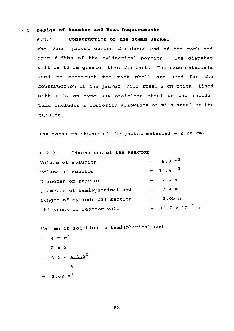
6.2 Design of Reactor and Heat Requirements
6.2.1 Construction of the Steam Jacket
The steam jacket covers the domed end of the tank and
four fifths of the cylindrical portion. Its diameter
will be 18 cm greater than the tank. The same materials
used to construct the tank shell are used for the
construction of the jacket, mild steel 2 cm thick, lined
with 0.28 cm type 304 stainless steel on the inside.
This includes a corrosion allowance of mild steel on the
outside.
The total thickness of the jacket material =2.28 cm.
6.2.2 Dimensions of the Reactor
Volume of solution = 9.0 m-j
Volume of reactor = 13.5m
Diameter of reactor = 2.4 m
Diameter of hemispherical end = 2.4 m
Length of cylindrical section = 3.05 m
Thickness of reactor wall = 12.7 x 10 m
Volume of solution in hemispherical end
= 4 n r 3
3x2
= 4 X 7T X 1.2 3
= 3.62 m
82

Therefore volume of solution in cylindrical section
= 9-3.62 = 5.38m3
using V = 7rr 2h
Then height of solution in cylindrical section, h
= v
TT r 2
h = 5.38 = 1.9 m
TT x 1.2 2
6.2.3 Agitator Design
A standard tank configuration, which provides adequate
mixing for most requirements, has the following
geometrical relationships ( 34 ).
1. The agitator is a six blade, flat blade turbine
impeller.
2. The impeller diameter is one third of the tank
diameter.
3. The height of the impeller from the tank bottom is
equal to the impeller diameter.
4. Impeller blade width is one fifth of the impeller
diameter.
5. The impeller blade length is one eighth of the
impeller diameter.
6. Four baffles, vertically mounted on the tank wall,
are employed extending above the liquid surface.
83

7. The baffle width is one tenth of the tank diameter.
As baffles are employed the agitator will be mounted
along the centre line of the vessel. The dimensions of
the mixer will be as follows:-
Agitator type 0.800 m
Impeller diameter 0.800 m
Height of impeller from bottom of tank 0.800 m
Each impeller blade width 0.160 m
Each impeller blade length 0.100 m
Number of baffles 4
Baffle width 0.24 m
Impeller speed 1.25 rev/s
From ( 34 ) the number of turbines to be used on a shaft
is given by Weber's formula
Number of turbines = ____WELH____
Tank diameter
where WELH = water equivalent of liquid height
Number of turbines = 3.6 = 1.7
2.2
Number of Turbines to be used——=——2
These are placed one impeller diameter apart (0.800 m)
to prevent the formation of unagitated areas.
84

6.2.4 Heat Transfer Area
A.^ = Inside heat transfer area = (TT x D • x L) + TT D • 2
4
where
D^ = Internal diameter = 2.4 m
L = Height of liquid in cylindrical section = 1.9 m
A^ = (TT x 2.4 x 1.9) + TT x 2 . 4 2
4
A = 18.86 m2
Similarly,2
4
= Outside heat transfer area = -n D_L + H__D_o —— o —
where
DQ = Outside diameter of reactor = 2.4254 m
A = (TT x 2.4254 x 1.9) + rr X 2.42S4 2
AQ = 19.11 m2
Mean heat transfer area = 18.98 m2
6.2.5 Jacket Side Heat Transfer Coefficient
The following equation applied to a vapour condensing on
a vertical tube
holKf 3 e f 2
85

where
hQ = Outside heat transfer coefficient
/-t f = Viscosity of condensing vapour
Kf = Thermal conductivity of condensing vapour
&f — Density of condensing vapour
G 1 = Mass flow rate/linear metre.
and /Lt f , Kf and e f are evaluated at temperature tf , the
condensing film temperature.
tf = \ (Tv - tw )
where
TV = Condensing vapour temperature
tw = Wall temperature.
TV is constant at constant pressure, but tw will vary
with the bulk liquid temperature.
If it is assumed that steam is available at 15 p.s.i.g.
and at a flow rate of 0.1 x 10 kg/sec, then from steam
tables ( 36) the value of TV will be 120 °c.
Assuming the temperature of the solution will drop to
50°C when the new batch of film is transferred to the
reactor then tw will vary from 50°C to 95°C.
Therefore, tf (i) = 85°C and t f (f) = 107 °C.
Taking tf as the mean i.e. 96.25°C and using values for/ 3 Q }
condensed steam at this temperature from * ' for ji f , Kf
86

and
= O.235 x 10 3 kg/ms
e f = 962 kg/m3
Kf = 0.674 W/m2 (°C/m)
G 1 = 0.1 x 10 kg/s
Therefore
G 1 = 1.0 = Mass Flowrate =
TT D Circumference TT x 2.4254
G 1 = 0.131 kg/ms
Therefore
h0 | (Q.235^ 2 X 10" 6______\ 1/3 = 1.47/ 4 X 0.131 V 1 / 3
(0.674) 3 X (962) 2 X 9.81 ^0.235 X 10~ 3 /
h = Heat transfer coefficient for condensing steam
= 4154 Wm~ 2 °C
6.2.6 Inside Heat Transfer Coefficient
As the solution is mainly water the values for density,
thermal conductivity and specific heat of water are
taken as those for the solution as a whole. As these
values are fairly constant over the temperature range
considered ( 36 ) the arithmetic mean is taken in each
case.
The values for these constants are:
87

Cp = Thermal capacity = 4.2 kJ/kg K
p = Density = 975 kg/m3
fj. = Viscosity = 0.038 kg/ms
K = Thermal conductivity = 0.652 W/m2 (°C/m)
Brooks and Su^ 37 ) have developed the following equation
for jacketed reactors where the Reynolds number is
greater than 400.
h,_Dt = 0.74 (Re)°' 67 (Pr)°- 33 ~0.14J. C. * ' \ i
K
(N.B. At the low temperature range usedf £., Vis
I /\ ^ '
approximately one) .
where
h^ = Inside heat transfer coefficient (Wm~ 2 °C~ 1 )
Dt = Diameter of tank (m)
Re = Reynolds number for mixing
Pr = Prandtl number
As Re = PNDa2
Mw
where
N = Impeller speed (rev.s" 1 ) =1.25 s" 1
Da = Diameter of impeller (m) = 0.800 m
IL = Viscosity at wall temperature = 0.038 kg/ms
88

Then
Re = 962 X 1.25 x (0.800) 2
0. 038
Re = 20253
Pr = Cp_±i
K
Therefore
h.^ X 2.4 = 0.74 X (20253) 2 / 3 x 4 .2 X 10 3 X 0.038 1 / 3
0.652 0.652
h i = 934 Win" 2 °C~ 1
Inside heat transfer coefficient = 934 Wm~ 2 °C~ I
6.2.7 Overall Heat Transfer Coefficient
There are four resistances to heat transfer.
1. Inside film (water side) = 1/h^.
2. Reactor wall = 1/K.
3. Outside film (jacket side) = l/hQ .
4. Scale and dirt on reactor wall = Rd -
l = l + 1 + 1 +
UA hi A± K Aj, h0 AQ
where
K = Thermal conductivity of reactor wall
1 = Thickness of reactor wall
A-_ = Logarithmic mean area of heat transfer
U = Overall heat transfer coefficient per m2
1 = overall resistance to heat transfer per m2
U
89

AS A = A = 1.0
Ao Ao
Therefore
i = 1_ + 1 + 1 + R,, —— ct
U hi K h0
Now
1 = 12.7 x 10~ 3 m
K =48.5 Wm~ 2 (°C/m) (37)
From Kern^ 35 ) Rd may be taken as 0.88 x 10~ 3 m2 °C/W
Therefore
JL = 1 + 1 + 12.7 x 10" 3 + 0.88 x 10~ 3
U 934 4154 48.5
U = 406.3 Wm~2 °C~ 1
Overall heat transfer coefficient including scale
resistance = 406.3 Wm~ 2 °C~ 1
6.2.8 Heating Time
In an agitated vessel containing Mkg of liquid with
specific heat Cp and initial temperature t, heated by a
condensing medium of constant temperature Ts, the batch
temperature at any given time 0 is given by the
differential balance
dQ = MCp dt
d9
90
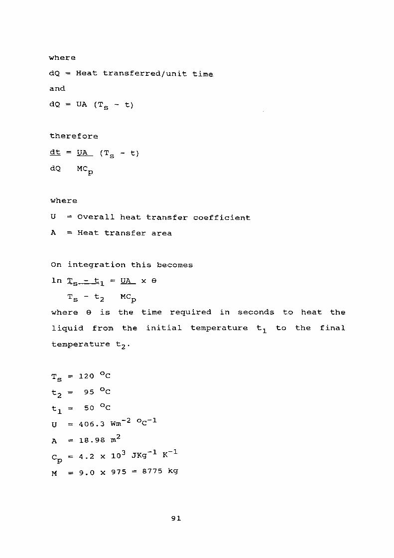
where
dQ = Heat transferred/unit time
and
dQ = UA (Ts - t)
therefore
dt = UA (Ts - t)
dQ MCp
where
U = Overall heat transfer coefficient
A = Heat transfer area
On integration this becomes
In Ts_=_t-L = UA x 8
Ts - fc 2 Mcp
where 9 is the time required in seconds to heat the
liquid from the initial temperature t^_ to the final
temperature ^2 •
Ts = 120 °C
t = 95 °C
t x = 50 °C
U = 406.3 Wm~ 2 °C~ 1
A = 18.98 m2
C = 4.2 X 10 3 JKg" 1 K" 1"
M = 9.0 x 975 = 8775 kg
91
Therefore
In [ 120 - 50 j = 406.3 x 18.98 x Q
\120 - 95/ 8775 x 4.2 X 10 3
e = 1 hour 22 mins
Time required to heat, batch of solution containing one
tonne of film from 50°C to 95°C is 1 hour 22 mins.
92

CHAPTER SEVEN
Management and Recycling
7.1 Introduction
7.2 Marketing and Economy
7.3 Usage of PET
93

7.i introduction
The European Commission made it clear ( 38 ) the energy
recycling of plastic by incineration is not a preferred
option, and strongly believe in plastic recycling as the
solution to waste treatment.
Thermal recycling of plastic is a solution for waste
management, but it should be limited to that fraction of
plastic waste which may not be recycled by chemical or
physico-mechanical treatment.
The European Community ( 39 ) plans to promote the favoured
option of plastic recycling, these include:
1. Substantial VAT reductions for recycled products.
2. Reserving public contracts entirely for recycled
products.
3 . Establishing of information centres dealing with
availability of plastic wastes.
4. Organising financial assistance for research and
development of plastic recycling technology.
Waste Management strategy is based on three principles:
1. Waste prevention in plastic, means recycling or changing
the surface coating of the plastic and clean technology.
2. Increase of recycling.
3. Safe disposal.
94

7.2 Marketing and Economy
PET is a significant influence and one of the most popular
plastics in the world for several reasons:
A. The reason behind the increase in this material is that
a good oxygen and carbon dioxide barrier, of around 0.52cc/m /24 hrs is obtained i.e. the market moved to replace the
12 ounce aluminium cans with PET cans. The barrier coating
used is Saran Polymer (PVDC).
The difficulty of removing Saran makes PET film difficult to
recycle.
B. Changes in lifestyle in recent years have also boosted
PET film demand. The key factor behind this is the
development and more importantly growth of microwave ovens.
European consumption of PET in microwave ovens is growing
fast at about 200 tonnes a year ^ 39 ^ .
C. One of the most popular products in the
construction industry is for spun bond road matting furnished
by the textile industry. The material is made from poly
(ethylene terephthalate) PET.
D PET film, offers a good barrier to both oxygen and
water, highly resistant to heat, chemicals and ultra violet
rays. This has increased its share of the European packaging
95

market.
Figure Number (7)
Total: 6250 KT
1984
Total; 7150 kT
1990
Plastics consumption in packaging, West Europe
Around 3.1% of the total market in 1990 involved PET compared
with 1.4% in 1984.
96
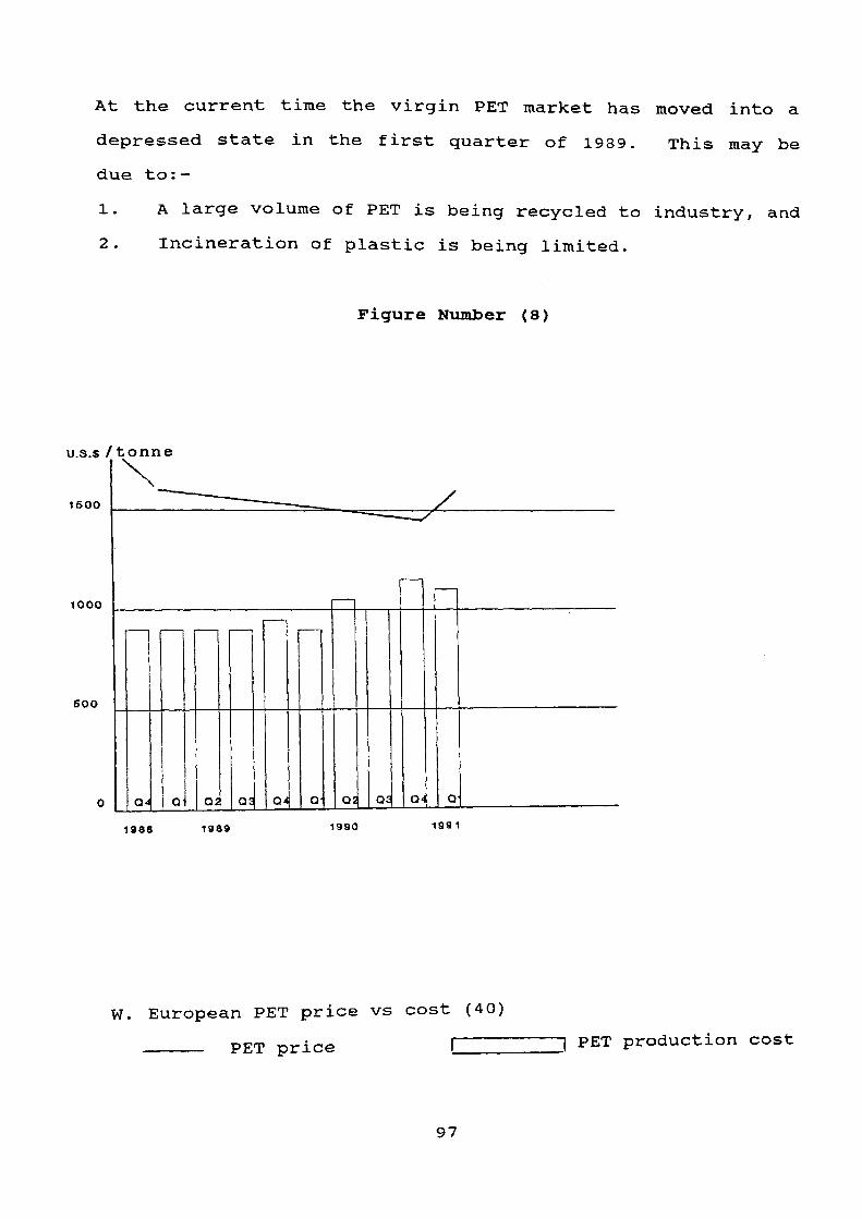
At the current time the virgin PET market has moved into a
depressed state in the first quarter of 1989. This may be
due to:-
1. A large volume of PET is being recycled to industry, and
2. Incineration of plastic is being limited.
Figure Number (8)
u.s.s / tonne
1600
1000
5OO
Q4 O Q5 Q4 Q QJ QS Q
1988 1989 1990 199 1
W. European PET price vs cost (40)
———— PET price r ~) PET production cost
97

The price situation may be difficult to understand when
viewed against the volume demand side of the market depending
on the weather conditions in Europe (i.e. The warmer the
weather the higher the demand, resulting in higher PET
prices).
Industry sources expect there will be continued upward
pressure on production of virgin PET in the ninety's and it
is anticipated that this could lead to an increase in demand
for the recycled PET, from bottle and film sources. This
demand will come from companies engaged in the manufacturing
of polyester fibres, carpets, packaging material, industrial
strapping, show fence, non-woven textiles and construction
material. Manufacturers using PET are currently paying £1.20
per kilo for virgin material and about £0.50 per kilo for
recycled PET bottle material. The PET recycled from film
will be priced at £0.40 per kilo, which makes it a
competitive commodity.
There are many benefits in recycling:
A. Provides available alternative and accessible raw
materials.
B. Reduces imports of primary raw materials and finished
products, and increases exports both of which have a
beneficial effect on the balance of payments.
C. Reduces the solid waste disposal problems and protects
98

our environment from salvageable waste, which would otherwise
go to landfill or incineration.
D. Reduces the waste of our natural wealth.
E. Saves energy.
F. Contributes to the conservation of the environment for
present and future generations.
7.3 Usage of PET
Typical usage area for pure/recycled PET with acceptable
viscosities:
A. Electrical outlets include:
1. Slot liners for electrical motors.
2. Wire and cable insulation.
3. Transformer insulation.
4. Capacitors.
5. Printed and laminated circuitry.
B. Variable outlets include:
6. Magnetic recording tapes.
7. Magnetic memory cards.
8. Microphone diaphragms and loudspeakers.
9. Typewriter ribbons.
10. Computer tapes.
11. Pressure - sensitive tapes.
12. Metallic yarn.
99

13. Decorative laminates on automobiles
14. Echo satellite balloons.
15. Missile diaphragms.
16. Very light aircraft.
17. Glazing applications.
18. Industrial belting.
19. Book jackets.
20. Apparel stays.
21. Roll leaf application.
22. Acoustic tiles.
23. Spring roll shelving.
24. Ticker tape.
25. Pipe wrap.
26. Photographic film base.
27. Packaging.
28. Boil-in-the-bag food application.
29. Heat - shrinkable wrappings.
30. Window coating.
31. Formable packages.
32. Plastic bottles.
33. Engineering reproduction.
34. Graphic art film.
35. Decals.
100

CHAPTER EIGHT
Description of a Recommended Plant and Control
8 . i Description of a Recommended Plant
8.2 Instrumentation and Control of Plant
101

8.1 Description of a Recommended Plant
The recommended recovery plant of PET from used X-ray film
illustrated in (Figure 9) comprises a pulveriser where the
film and paper is shredded to small particles; a hammer mill
is chosen for this type of duty. The particle size of
material leaving the mill is of the order of magnitude 10 -
25 mm. The pulverised paper and X-ray film mixture is
transported via a paddle blower through a vertical ducting
pipe 300mm diameter and 4m high ( 3 ) where the heavy material,
mainly consisting of metals, glass and stones are separated
from the paper/film mix.
The paper/film mix is then directed to an air classifier
where the light loose paper fraction is separated from the
film. The material is then transported to a reactor (Tl)
where the silver in the X-ray film is leached out using
alkaline cyanide solution and the silver recovered at the
cathodes of the electrolysis cells. The gelatin compound is
recovered at this stage using a filter press installed with
the same cycle. A neutralisation unit is needed to
neutralise the cyanide on the surface of the film using
sodium hypochlorite solution.
The material is then blown to the hot reactor (T2) containing
wetting agent in alkali solution controlled to pH of 10 - 11.
The temperature of the reactor (T2) is raised to 95 °C, the
agitation is provided by flat turbine impellers. At this
stage almost all PVDC and loose adhesive tapes are separated
102
from the PET.
Then the material is transported by a blower to a washing
tank (T3) controlled to pH of 6 - 8 using dilute sulphuric
acid at a temperature of 15 - 25 °c. Air at 1350 kN/m2 is
introduced at the bottom of the tank through spargers to
maintain uniform agitation and provide a lift off of the
small particles of flaked PVDC and the adhesive loose tape at
the top of the tank and then recovered by filtration.
The PET is conveyed to a continuous centrifuge system to
extract most of the surface moisture, and then transported to
a dryer. The resulting clean blue coloured PET is blended
50:50 with virgin PET in a hopper blender. The blended
product fed to a double screw pelletiser and then packed in
bags using a vacuum packer.
See the flow sheet in Appendix B, page 110 ..
103

8.2 Instrumentation and Control of Plant
As can be seen from the flowsheet, three controllers are
required.
Temperature Controller
This controls the reactor temperature and will be a simple
proportional flow controller which will record the
temperature and operate the cooling water and steam valves as
necessary to maintain the temperature at 95 °C.
In case of a failure in the controller system the reactor
should also have temperature recorder with an alarm signal on
the control panel designed to operate if the reactor
temperature goes too high or low during reaction. In this
event the valves would be operated manually. In addition, a
manually operated valve on a by-pass line over the
inlet/outlet valve could be installed in case of valve
failure.
pH Controller
The requirement of this controller is to adjust the set point
of the sodium hydroxide input controller to pH of 10 -11 in
(T2) . Also to reduce the pH of the solution in (T3) to pH of
6-7.
Therefore, the controller and valves must give a system which
has little steady state error, but it is unnecessary to have
a system with a fast response. The most suitable type of
104
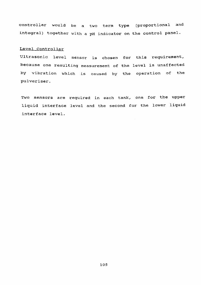
controller would be a two term type (proportional and
integral) together with a pH indicator on the control panel.
Level Controller
Ultrasonic level sensor is chosen for this requirement,
because one resulting measurement of the level is unaffected
by vibration which is caused by the operation of the
pulveriser.
Two sensors are required in each tank, one for the upper
liquid interface level and the second for the lower liquid
interface level.
105

References
Edwards, A. (1987), Manufacturing Chemist, March, 66.
2- Wereke Witten, c. (1959), British Patent No. 824, 624.
~" !! 1 !:at ' J -> Hokik, C. and Bacak, M. (1959), British Patent No. 822, 834.
4. Garcia, R.M. (1986), Hydr oraeta 1 lury Vol. 16, 395, Pub: fciszver Science.
5. Muench, w., Spano, L. and Notarbartolo , L. (1956), British Patent No 762, 690.
6. Currie, R.M. , Miller, D.N. and Measamer, S.G. (1975), U.S. Patent No 3, 907, 868.
7. Barna N. , Johnstud G. and Lampartor C. (1958), U.S. Patent No 2, 832, 663.
8. Fassell, W.M. and Bridges, D.W. (1976), U.S. Patent No 3, 953, 502.
9. Barkey, K.T., Douglas, C. and Leffets, E.B. (1970), U.S. Patent No 3, 488, 298.
10. Woo, T.K., Glowe, D.E. and Thornton, J.S. (1975), U.S. Patent No 3, 873, 314.
11. Gerber, H. and Wainer, E. (1978), U.S. Patent No 4, 078, 916.
12. Wainer, E. (1972), U.S. Patent No 3, 647, 422.
13. Thornton, S. and Glowe, D.E. (1975), U.S. Patent No 3, 928, 253.
14. Phillips, P. (1979), U.S. Patent No 4, 150, 977.
15. Du Pont, (1961), British Patent No 870, 639.
16. Reinhardt, R.C. (1943), Polymer Ind. and Eng. Chemistry, Vol. 35 No. 4, 422.
17. (1981), Pub: John Wiley and Sons, Kirk-othmer, Third Ed., Vol. 14.
18. (1983), Pub: John Wiley and Sons, Kirk-othmer, Third Ed., Vol. 23.
19. Wessling, R.A. (1970), Journal of Polymer Science, Vol. 14, 1531.
20. Raab, J. (1961), Journal of Polymer Science, Vol. 55, 821.
106

Ed " vol80 ^ ' Pub: J°hn Wiley and Sons, Kirk-othmer, Third
J°hn Wiley and Sons ' Kirk-othmer, Third
Thl T^linege ^ D<J - (1979), Film Sheets and Laminates, Pub: The International Plastic Selector, Inc.
Ed"
25. (1978), Pub: John Wiley and Sons, Kirk-othemer , Third td. , Vol . 2 .
26. (1989), Pub: Degussa Company, Standard Silver Test.
27. (1983), ASTM D1505 and D1156.
28. Stewart, J.J. (1959), U.S. Patent No 824, 624.
29. Chapman, A.F. (1954), U.S. Patent No 2, 824, 024.
30. Howard, G.J. and Knutton, S. (1975), Journal of App . Polymer Sc., Vol. 19, 683.
31. Herbert, R.S. (1964), Encyclopaedia of Plastic Equ. , Vol. 14, Pub: Renhold Publishing Co.
32. (1983), ASTM D2857.
33. (1983), ASTM D882.
34. Holland, F. and Chapman, F. (1966), Liquid Mixing and Processing in Stirred Tanks, Pub: Reinhold Publishing Corp.
35. Kern, D.Q. (1950), Process Heat Transfer, International Ed. , Pub: McGraw Hill Co.
36. Mayhew, Y.R. and Rogers, G.F. (1970), Thermodynamic and Transport Properties of Fluids, Pub: Blackwell (Oxford) .
37. Brooks, G. and Su, G.J. (1960), Chem. Eng . Progr . , No. 56, 237.
38. (1989), Bulletin Warmer, No. 23, Spring, Pub: The Warmer Campaign.
39. (1990), Bulletin Warmer, No. 23, Winter, Pub: The Warmer Campaign.
40. Wetzel, J.P. (1987), Swiss Plastics, Vol. 9, 7, Pub: European Single Service Asso. (ESSA) .
107

Appendix A
*Large Exposure : x-ray film where 70% of the silver
'* in the plate has been leached out
during the developing process.
* Low Exposure x- ray film where 40% of the silver
in the plate has been leached out
during the developing process.
*Green
*Total Exposure
Unexposed (unused) x- ray film.
X- ray film where all the silver in
the plate has been leached out.
*Clean film De-silver/de-laminated x-ray film.
108

Appendix A (cont..)
Exposed film : Lithographic film where 40% of the silver
in the plate has been leached out
during the developing process.
*Green film : Unexposed (unused) lithogaphic film.
*clean film : De-silver/de-laminated lithogaphic
'J film.
Pure silver : 99.9% silver ingots,
109

Oil
Q •-O
I Neutralization L-en
m o O
m
m o
O
enn: m m
9* T3•nM=5a
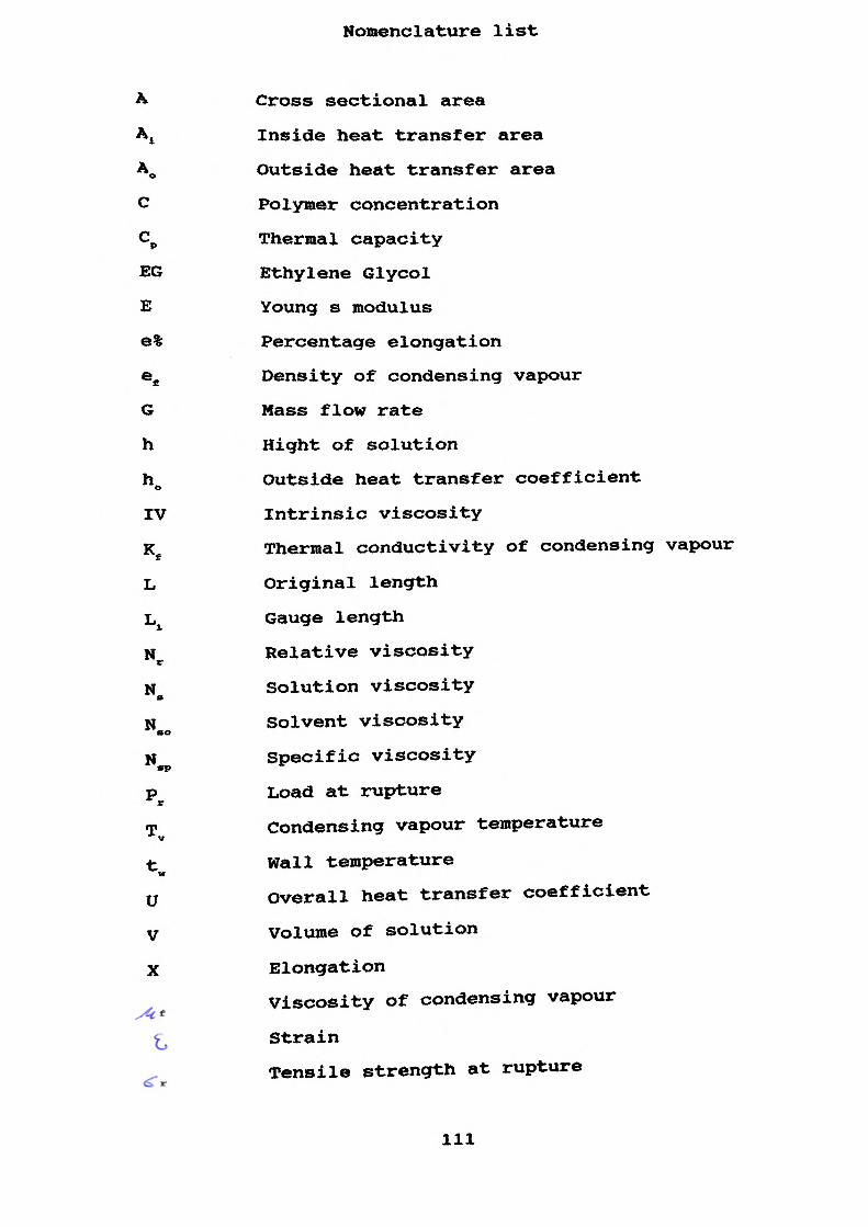
Nomenclature list
Cross sectional area
4 Inside heat transfer area
Ao Outside heat transfer area
C Polymer concentration
cp Thermal capacity
EG Ethylene Glycol
E Young s modulus
®% Percentage elongation
ee Density of condensing vapour
G Mass flow rate
h Hight of solution
h0 Outside heat transfer coefficient
IV Intrinsic viscosity
Ke Thermal conductivity of condensing vapour
L Original length
Lx Gauge length
Nr Relative viscosity
H. Solution viscosity
N Solvent viscosity*o
N Specific viscosity»pPr Load at rupture
T Condensing vapour temperature
tw Wall temperature
O Overall heat transfer coefficient
V Volume of solution
X Elongation
Viscosity of condensing vapour
Strain
Tensile strength at rupture
111