204cm manual v2.0 - dmt
TRANSCRIPT

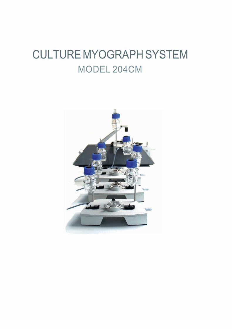
CULTURE MYOGRAPH SYSTEM MODEL 204CM

TRADEMARKS
Danish Myo Technology A/S reserves the right to alter specifications as required. This document was, as far as possible, accurate at the time of printing. Changes may have been made to the software and hardware it since then. New information may be
supplied separately.
This documentation is provided with a Culture Myograph System – 204CM
No part of this document may be reproduced by any means without
the prior written permission of Danish Myo Technology A/S.
Copyright © Danish Myo Technology A/S

Contents
Safety ................................................................................................................................................................................................ 3 EMC/EMI ................................................................................................................................................................................ 4 Approvals ............................................................................................................................................................................................... 4 Certificate of Conformity ................................................................................................................................................. 5 About this Manual ........................................................................................................................................................ 6
Unpacking the Myograph System… ....................................................................................................................................... 7
Chapter 1 - System Overview ............................................................................................................................................... 8 1.1 Culture Myograph Unit ............................................................................................................................................................. 8 1.2 DMT Microscope ...................................................................................................................................................................... 9 1.3 Culture Myograph Heat Controller ........................................................................................................................................... 9
Chapter 2 - Setting up ........................................................................................................................................................ 10 2.1 The Complete Culture Myograph System – 204CM .............................................................................................................. 10 2.2 Setting up the Complete Culture Myograph System 204CM ................................................................................................. 11 2.3 Installation of MyoVIEW ......................................................................................................................................................... 11
2.3.1 DMT Driver Package installation ............................................................................................................................ 11 2.3.2 MyoVIEW Installation ............................................................................................................................................................................................... 12
2.4 Experiment Setup ................................................................................................................................................................. 14 2.4.1 Connecting the Flow-Reservoirs ............................................................................................................................ 14
2.5 Perfusion Flow Control ........................................................................................................................................................... 15 2.5.1 Setup and Control of Superfusion Flow ............................................................................................................................... 16
Chapter 3 - DMT 204CM Control Program ......................................................................................................................... 16 3.1 Control of Temperature and Light Intensity ..................................................................................................................... 16
Chapter 4 - Culture Myograph Manual ............................................................................................................................... 17 4.1 The Culture Myograph Unit ................................................................................................................................................... 17
4.1.1 Glass Cannula Adjustment ................................................................................................................................................... 18 4.1.2 Removal and Mounting of Glass Cannulas and Chamber ............................................................................................... 19 4.1.3 Changing O-rings ............................................................................................................................................................ 20
4.2 The DMT Microscope ............................................................................................................................................................. 21 4.3 Pressure Regulator ......................................................................................................................................................................... 21 4.4 Culture Myograph Maintenance ........................................................................................................................................... 22
Chapter 5 - Getting Started ............................................................................................................................................... 23 5.1 Dissection Protocol for Small Mesenteric Arteries ................................................................................................................ 23 5.2 Mounting Protocol for Small Arteries .................................................................................................................................... 26 5.3 Buffer Recipes ...................................................................................................................................................................... 27
Appendix 1 - Fuse Changing .............................................................................................................................................. 29 Appendix 2 - System Specifications ................................................................................................................................... 30

Safety The Culture Myograph System has been designed for use only in teaching and research applications. It is not intended for clini- cal or critical life-care use and should never be used for these purposes: nor for the prevention, diagnosis, curing, treatment, or alleviation of disease, injury or handicap.
• Do not open the unit: the internal electronics pose a risk of electric shock.
• Do not use this apparatus near water.
• To reduce the risk of fire or electric shock, do not expose this apparatus to rain or moisture. Objects filled with liquids should
not be placed on the apparatus. • Do not block any ventilation openings. Install in accordance with the manufacturer’s instructions.
• Do not install near any heat sources such as radiators, heat registers, stoves, or other apparatus that produce heat.
• Only use attachments and accessories specified by the manufacturer.
• Unplug this apparatus during lightning storms or when unused for long periods of time.
• This apparatus must be earthed.
• Use a three-wire grounding-type cord similar to the one supplied with the product.
• Do not defeat the safety purpose of the polarized or grounding-type plug. A polarized plug has two flat blades, one being
wider than the other. A grounding type plug has two blades and a third (round) grounding pin. The wide blade or the third prong is provided for your safety. If the provided plug does not fit into your outlet, consult an electrician for replacement of the obsolete outlet.
• Be advised that different operating voltages require the use of different types of line cord and attachment plugs. Check the
voltage in your area and use the correct type. See the table below: Voltage Line plug according to standard
110–125 V UL817 and CSA C22.2 No. 42. 220–230 V CEE 7 page VII, SR section 107-2-D1/IEC 83, page C4.
240 V BS 1363 of 1984. Specification for 13A fused plugs and switched and unswitched socket outlets.
Protect the power cord from being walked on or pinched: particularly at power plugs and the point where they connect to the apparatus.
Refer all servicing to qualified service personnel. Servicing is required when the apparatus has been damaged in any way;; such as, the power-supply cord or plug is damaged, liquid has been spilled onto or objects have fallen into the apparatus, the appara- tus has been exposed to rain or moisture, does not operate normally, or has been dropped.
3

EMC/EMI
This equipment has been tested and found to comply with the limits for a Class B Digital device, pursuant to part 15 of the FCC rules. These limits are designed to provide reasonable protection against harmful interference in residential installations. This equipment generates, uses and can radiate radio frequency energy and, if not installed and used in accordance with the instruc- tions, may cause harmful interference to radio communications. However, there is no guarantee that interference will not occur in a particular installation. If this equipment does cause harmful interference to radio or television reception (which can be deter- mined by monitoring the interference while turning the equipment off and on), the user is encouraged to correct the interference by one or more of the following measures:
• Reorient or relocate the receiving antenna. • Increase the separation between the equipment and receiver. • Connect the equipment into an outlet on a circuit different to that to which the receiver is connected to. • Consult the dealer or an experienced radio/TV technician for help.
Approvals
Complies with the EMC standards: EMC 89/336/EEC: EN 50 081-1 and EN 50 082-1 FCC part 15, Class B CISPR 22, Class B
Certified with the safety standards: EN 60 065 (IEC 60065)
Complies with the safety standards: UL6500 CSA E65
4

5
hereby declares its responsibility that the following product:
is covered by this certificate and marked with CE-label and conforms with the following standards:
EN 60 065 (IEC 65) and related apparatus for household and similar general use.
EN 50 081-1 Part 1: Residential, commercial and light industry.
EN 50 082-1 Part 1: Residential, commercial and light industry.
With reference to regulations in the following directives: 73/23/EEC, 89/336/EEC

About this Manual This manual contains a complete list of procedures describing how to install, maintain and get started using the Culture Myo- graph System – Model 204CM – Version 1.6.
Chapter 1 provides a comprehensive view of the construction and basic features of the complete Culture Myograph System.
Chapter 2 describes step-by-step how to set-up a complete 204CM Culture Myograph System, including all various accessories.
Chapter 3 describes Control of Temperature and Light Intensity
Chapter 4 is a complete manual to the Culture Myograph System. The chapter describes in detail how to use the DMT micro- scope, how to use and adjust the culture myograph chamber and finally instructions for the daily maintenance of the Culture Myograph System.
Chapter 5 contains procedures describing how to get started using the wire myograph system. This includes a complete dissec- tion and mounting procedure.
Appendixes contain additional information about fuse changing and system specifications.
6

Unpacking the Myograph System Please take a few minutes to carefully inspect your new Culture Myograph System for any damage, which may have occurred dur- ing handling and shipping. If you suspect any kind of damage, please contact DMT immediately and the matter will be pursued as soon as possible. If the packing material appears damaged, please retain it until a possible claim has been settled. We recommend that you store the packing material for any possible future transport of the Culture Myograph System. In case of transport and the original packing material is unavailable, please contact DMT Sales Department for advice and packing instruc- tion. After unpacking your new Culture Myograph System, please use the following list to check that the system is complete: 1. Culture Myograph Unit: • 4 Culture Myograph Chambers with Chamber Cover. • 2 Glass Cannulas (Tip outer diameter 125µm) per chamber. • 2 Schott Duran Bottles 25ml per chamber.
2. DMT Microscope: • Temperature Probe. • Olympus Objective Micrometer including Microscope Objective Holder.
3. Culture Myograph Heat Controller Unit: • USB-cable for connection to PC. • Power cord (The shape of the AC plug varies by country;; be sure that the plug has the right shape for your location).
4. Pressure Regulator
5. Accessories: • Small Screwdriver. • 3 m. Nylon Suture. • 8 blind plugs including six O-rings (1.07×1.27mm) for the Culture Myograph Chamber. • 10 O-rings (5.0×1.0mm) for fixation of left glass cannula. • 10 O-rings (18.0×1.0mm) for cover • 5 O-rings (1.07×1.27mm) for chamber.
6. Software & Manuals: • 1 CD with user manual for “Culture Myograph System – Model 204CM”. • 1 CD with MyoVIEW data acquisition software
7. Peristaltic Pump (Optional):
8. Computer (Optional)
7

Chapter 1 - System Overview
1.1 Culture Myograph Unit
Cable to myo- Interface
Vertical regulation plate for left glass cannula
Micropositioner for longitudinal regulation of right glass cannula
O-ring locks fixing the left glass cannula Fixation and longitudinal
regulation plate for right glass cannula
Screw for horizontal regula- tion of both glass cannulas
Left glass cannula (Tip outer diameter 125µm)
Myograph chamber access hole for left glass cannula
Superfusion inlet
Superfusion outlet
Right glass cannula (Tip outer diameter 125μm)
Myograph chamber access hole for right glass cannula
Culture myograph unit / chamber assembly mark
Figure 1.1 Culture Myograph Chamber Unit 8

1.2 DMT Microscope
Plug for connection of temperature probe
Infrared light scource Zeiss Achromat 10X / 0.25 objective
X Y Z level regulation of objective focus
Figure 1.2 DMT Microscope
1.3 Culture Myograph Heat Controller
Power ON Led
Connection to the Culture Myograph Units
USB-Port for Connection to Computer ON / OFF Switch
Power Inlet
Figure 1.3 Heat Controller 9
Unit (Fig. 1.1)

Chapter 2 - Setting up 2.1 The Complete Culture Myograph System – 204CM
Figure 2.1 Setting up step by step. In the figure, the superflow is only connected for the chamber on the DMT microscope. Superflow also has to be connected to the three other chambers as well
NOTE: IF YOU HAVE PURCHASED A COMPUTER FROM DMT IN CONJUNCTION WITH YOUR CULTURE MYOGRAH 204CM SYSTEM THE MyoVIEW DATA ACQUISITION SOFTWARE HAS ALREADY BEEN INSTALLED ALONG WITH DRIVERS. FOLLOW THE PROCEDURES IN SECTION 2.2 TO SET-UP THE CULTURE MYOGRAPH SYSTEM.
IF YOU HAVE NOT PURCHASED A COMPUTER FROM DMT, PLEASE FOLLOW THE PROCEDURES IN SECTION 2.3 TO INSTALL THE MyoVIEW DATA ACQUISITION SOFTWARE ON YOUR OWN COMPUTER.
10
2.2 Setting up the Complete Culture Myograph System 204CM 1. Ensure that the heat controller is switched off, on the rear panel before proceeding with the connection procedure.
2. Connect the loose cables from the four culture myograph units to the front panel of the heat controller.
3. Connect the power cord to the power inlet on the back panel of the heat controller.
4. Connect the Heat Controller to the PC with the loose USB cable using the USB port on the Heat Controller and a free USB
port on the PC. 5. Connect the DMT Microscope to a USB port on the computer using the fixed USB cord.
6. Turn on the power switch of the heat controller.
7. The Power ON LED on the front panel of the heat controller should be lit indicating that the heat controller is on.
8. Turn on the computer.
2.3 Installation of MyoVIEW This section describes how to install the MyoVIEW Software on your computer along with drivers for the digital USB camera. NOTE: IF YOU HAVE PURCHASED A COMPUTER FROM DMT ALONG WITH YOUR CULTURE MYOGRAPH - 202CM SYSTEM THE DRIVERS AND THE MyoVIEW SOFTWARE HAVE ALREADY BEEN INSTALLED FOR YOU. NOTE: MyoVIEW DEMANDS A 64BIT COMPUTER INSTALLED WITH WINDOWS 7 OR NEWER.
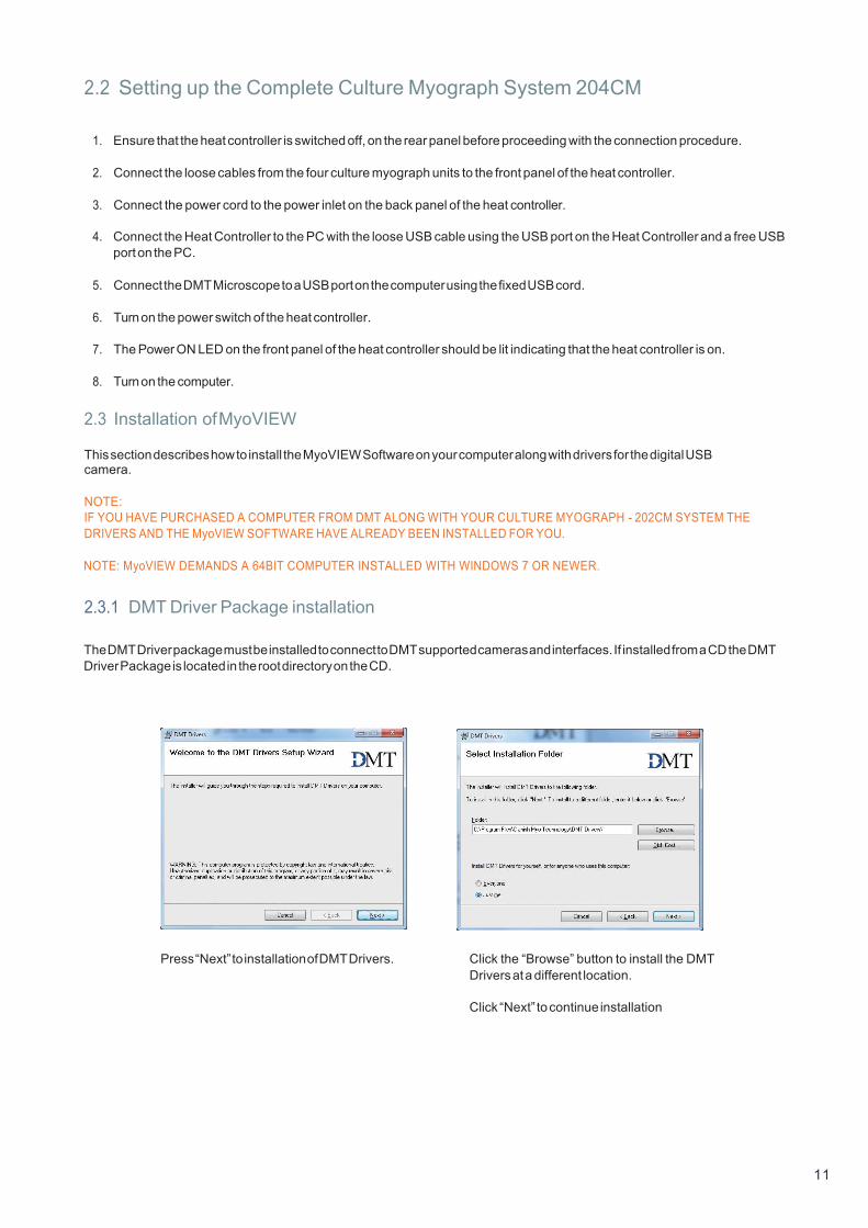
2.3.1 DMT Driver Package installation The DMT Driver package must be installed to connect to DMT supported cameras and interfaces. If installed from a CD the DMT Driver Package is located in the root directory on the CD.
Press “Next” to installation of DMT Drivers. Click the “Browse” button to install the DMT Drivers at a different location.
Click “Next” to continue installation
11
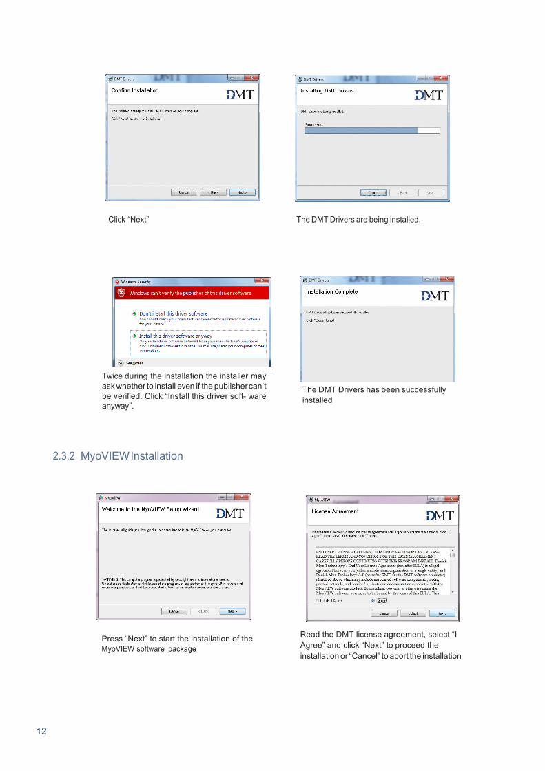
Click “Next” The DMT Drivers are being installed.
2.3.2 MyoVIEW Installation
Press “Next” to start the installation of the MyoVIEW software package
Read the DMT license agreement, select “I Agree” and click “Next” to proceed the installation or “Cancel” to abort the installation
12
Twice during the installation the installer may ask whether to install even if the publisher can’t be verified. Click “Install this driver soft- ware anyway”.
The DMT Drivers has been successfully installed

Click the “Browse” button to install MyoVIEW at a different location.
Click “Next” to continue installation
Click “Next” to start the installation
MyoVIEW are being installed The installation of MyoVIEW is now complete. Click “Close” to end installation
13

2.4 Experiment Setup
2.4.1 Connecting the Flow-Reservoirs
To connect the flow reservoirs with the glass cannulas and the Pressure Regulator, DMT recommends PharMed™ tubes (Product No. 100127 ):
NOTE: A STERILE MICRO FILTER (0.20ΜM) IS CONNECTED BETWEEN THE PRESSURE MANOMETER RESERVOIR AND THE TWO PERFUSION RESERVOIRS TO PREVENT CONTAMINATION OF THE PERFUSION BUFFER.
Figure 2.2 Illustration of how to connect flow reservoirs. 14

2.5 Perfusion Flow Control Regulating the difference in height between the two flow reservoirs allows control of the perfusion flow velocity. The principle is illustrated in Fig. 2.3. In Fig. 2.3A the two reservoirs are equal in height and no flow will occur. In Fig. 2.3B the difference in height reveals a flow from the right reservoir to the left reservoir. NOTE: TO ENABLE THE PERFUSION FLOW, IT IS IMPORTANT THAT THE RIGHT GLASS CANNULA IS CONNECTED TO THE LONG STEEL PIPE IN THE RIGHT RESERVOIR (MARKED BY THE ARROW IN FIG. 2.3 A).
Figure 2.3 A and B Illustration of perfusion flow control
15

2.5.1 Setup and Control of Superfusion Flow
Waste Bottle
Figure 2.4 Illustration of perfusion flow control
The superfusion circuit consists of an inflow and an outflow from the culture myograph chamber. Both flows are driven by the same peristaltic pump, which leads the superfusion buffer from the reservoir to the culture myograph chamber and finally to a waste bottle. The small steel pipe on the culture myograph chamber cover is connected to a sterile micro filter (0.20µm). The small pipe works as a breathing valve to prevent over pressure in the culture myograph chamber.
The superfusion buffer reservoir is continuously aerated with a mixture of 95% O 2
micro filter (0.20µm) to prevent contamination of the sterile superfusion buffer. and 5% CO . The gas passes through a sterile
2
CHAPTER 3 - DMT 202CM CONTROL PROGRAM
3.1 Control of Temperature and Light Intensity
The temperature in the chamber and the light intensity of the Microscope light is controlled in the MyoVIEW software (see MyoVIEW for Culture Myograph System manual).
NOTE: MAKE SURE THAT THE HEAT CONTROLLER IS TURNED ON AND THE MICROSCOPE IS CONNECTED TO THE COMPUTER USING THE USB CABLES, BEFORE STARTING THE MyoVIEW SOFTWARE.
16
Buffer

Chapter 4 - Culture Myograph Manual 4.1 The Culture Myograph Unit The culture myograph unit is placed on the DMT microscope as illustrated in Fig. 4.1. Press the black lever to lock the culture myograph unit onto the DMT microscope.
4.1.1 Glass Cannula Adjustment
The glass cannulas are adjustable in all X Y Z directions. The adjustments are illustrated in figure 4.1.
Figure 4.1 Illustration of glass cannula adjustment
17

Horizontal Adjustment:
Horizontal adjustment is performed as illustrated in figure 4.1 on previous page and figure 4.2.
Gently loosen the screw fixing the chamber and carefully move the myograph chamber in either clockwise or counter clockwise direction to adjust the horizontal alignment of the glass cannulas.
Horizontal Adjustment Screw:
Loosen this screw and carefully turn clockwise or counter clockwise. Observe how the pipettes move in horizontal plane.
Figure 4.2 Horizontal adjustment of glass pipettes
Vertical Adjustment: Vertical adjustment is performed as illustrated in Fig. 4.1.
Gently turn the black dish, underneath the left glass cannula, clockwise or counter clockwise to adjust the vertical alignment of the glass cannulas.
Longitudinal Adjustment: Longitudinal adjustment of the glass cannulas is performed using the micro positioner on the right side of the culture myograph unit.
18

4.1.2 Removal and Mounting of Glass Cannulas and Chamber Replacement of glass cannulas and demounting of the culture myograph chamber for sterilization are common routines in cul- ture myograph experiments. The procedure illustrated in Fig. 4.3.
Fixation screw
Figure 4.3 How to free the glass cannulas from the culture myograph unit
Removal of Left Glass Cannula: Carefully remove the two O-rings (marked by the two arrows) to free the glass cannula from the culture myograph unit. Then care- fully unscrew the locknut and remove both locknut and glass cannula. Removal of right Glass Cannula: Gently remove the little screw (marked by the arrow) to free the glass cannula from the culture myograph unit. Then carefully unscrew the locknut and remove both locknut and glass cannula. Removal of Culture Myograph Chamber: After removal of both glass cannulas, loosen the horizontal adjustment screw to free and remove the chamber from the culture myograph chamber. Mounting of all parts is performed the same way, but in opposite direction.
19

4.1.3 Changing O-rings
Each locknut on the culture myograph chamber is equipped with rubber O-rings (ø1.07 x 1.27mm) to keep the chamber tight. These O-rings will from time to time need to be replaced. The procedure is illustrated in Fig. 4.4.
• Unscrew the locknut to reveal the O-ring and remove it carefully using small forceps or a similar tool.
• Insert the new O-ring into the chamber hole and push it back until it makes contact with the bottom of the hole.
• Carefully insert the glass cannula through the locknut and place it in the chamber hole. Gently tighten the locknut.
NOTE: BE CAREFUL NOT TO DAMAGE THE GLASS CANNULA TIPS WHEN DISASSEMBLING THE CULTURE MYOGRAPH CHAMBER.
20

4.2 The DMT Microscope The DMT microscope is an invert microscope equipped with a Zeiss Achromat 10X /0.25 objective and build-in digital USB CCD camera. The objective is adjustable in all X Y Z directions using the three micro positioners on the front as illustrated in figure 4.5.
Figure 4.5 How to adjust the position and focus of the microscope in the X Y Z directions.
The MyoVIEW obtains an image by measuring the differences in light intensity passing through the walls of a vessel segment mounted in the culture chamber. Traditionally a white light source is sufficient for such a purpose, but has one major disadvantage. A white light source makes the data acquisition and analysis very sensitive to changes in white light intensity from the surroundings, such as ambient light and sunlight. To avoid the surroundings influencing the data acquisition and analysis, the DMT microscope has a built-in infrared light source. 4.3 Pressure Regulator The Pressure Regulator is connected to the culture myograph system to generate a pressure on the mounted vessel from the perfusion buffer. The pressure is adjusted using the knob and air release valve shown in figure 4.6 below.
Figure 4.6 Pressure Regulator
NOTE DO NOT USE THE SMALL DISPLAY ON THE PRESSURE REGULATOR. ONLY USE THE KNOB TO ADJUST THE PRESSURE
21
Use only this knob to adjust the pressure on the Pressure Regulator

4.4 Culture Myograph Maintenance The Culture Myograph System – Model 204CM is a very delicate and sophisticated piece of research equipment. In order to keep it working at its best, DMT recommend that the following sections are read carefully and that the instructions are followed at all times.
DMT strongly recommends that the myograph chamber and surroundings be cleaned after each experiment.
After a “normal” experiment use the following procedure to clean the myograph chamber and glass cannulas:
1. Fill up the myograph chamber to the edge with an 8% acetic acid solution and allow it to stand for a few minutes to dissolve calcium deposits and other salt build-up. Use a swab stick to mechanically clean all chamber surfaces.
2. Remove the acetic acid and wash the myograph chamber and glass cannulas several times with double distilled water.
3. It is hard to remove any kind of hydrophobic reagent used by using step 1. and 2., try incubating the chamber and glass
cannulas with 96% ethanol or a weak detergent solution (e.g. Treepol).
4. To remove more resistant or toxic chemicals, incubate the myograph chamber and glass cannulas with 1M HCl for up to 2 minutes.
5. Wash the myograph chamber and glass cannulas several times with double distilled water.
IMPORTANT NOTES:
• TO STERILIZE THE CULTURE MYOGRAPH CHAMBER AND GLASS CANNULAS, USE A STANDARD AUTOCLAVE PROCE-
DURE. • BE VERY CAREFUL USING STEP 3 AND 4 REPEATEDLY AS STRONG REAGENTS CAN CAUSE EXTREME DAMAGE TO THE
MYOGRAPH UNIT. • BE VERY CAREFUL NOT TO DAMAGE THE GLASS CANNULAS DURING THE CLEANING PROCEDURE.
In cases of red or brown discolorations appearing on the chamber sides, the following cleaning procedure will work in most cases:
1. Incubate the myograph chamber for 30 minutes with 20µl of a 2mM T-1210 Tetrakis-(2-pyridylmethyl)-ethylenediamine solu-
tion dissolved in double distilled water.
2. Use a swab-stick to mechanically clean all the affected surfaces during the last 15 minutes of the incubation period.
3. Wash the myograph chamber several times with double distilled water.
4. Incubate the myograph chamber with 96% ethanol for 10 minutes while continuing the mechanical cleaning with a swab- stick.
5. Remove the ethanol solution and wash a few times with double distilled water. Incubate the myograph chamber with an 8%
acetic acid solution for 10 minutes and continue the mechanical cleaning with a swab-stick.
6. Wash the myograph chamber several times with double distilled water. 22

Chapter 5 - Getting Started 5.1 Dissection Protocol for Small Mesenteric Arteries The culture myograph technique is versatile in that a large variety of physiological and pharmacological studies of ring prepara- tions from different species can be performed. Mostly, the culture myograph is used for investigation of small blood vessels and as an example this chapter describes the dissection of rat mesenteric arteries. 1. A laboratory rat is euthanized in accordance to the local national law and regulations. A midline laparotomy is performed to
expose the mesenteric bed. 2. Use scissors to remove about 10cm of intestine along with its feeding vasculature, including part of the superior mesenteric
artery. Be careful not to damage the vasculature during this procedure. The proximal end of the intestine section must be about 10cm from pylorus. Make a cut in the proximal end of the intestine for later identification.
3. Place the excised intestine section in a Petri dish (about 9cm in diameter) coated with a 5mm thick layer of Sylgard at the
bottom to hold the fixing pins. Immediately fill the Petri dish with cold PSS well prebubbled with carbogen (see Chapter 5.3). The dissection is performed without further oxygenation of the PSS.
4. Pin down the proximal end of the intestine section on the left-hand side of the Petri dish without stretching the vessels. Pin
down the remaining of the intestine section in an anti-clockwise direction. In this configuration (proximal end at the left side, distal end at the right side and running anti-clockwise from proximal to distal side) the feeding vasculature is on the far side of the intestine and the veins are usually uppermost.
5. Select the vessel segment to be investigated (Fig. 5.1). First time myograph users are recommended to start dissecting
and mounting vessel segments from the first or second branch from the superior mesenteric artery (approximate internal diameter 200-300µm).
Figure 5.1 Branch of the mesenteric arteries
23

6. Use high quality forceps and ocular dissection scissors to dissect the vessel segment of interest. Start cutting through the mesenteric membrane along both sides of the vessel, about 1-2mm from the vessel. To avoid accidentally cutting the artery always cut along the length of the vessels and never perpendicular to them (Fig. 5.2 A-B).
Figure 7.2 Removal of adipose tissue around the area of interest
7. Dissect away as much adipose tissue as needed around the vessels to distinguish between the artery and vein. The artery can easily be identified by the following characteristics (Fig 5.3):
• The branch points of arteries are V-shaped whereas those of veins are more U-shaped.
• The arterial wall contains a thick layer of smooth muscle cells compared to the vein wall, which only contains a single or
a few layers of smooth muscle cells. The histological difference is clearly visible in the stereo microscope.
• If you still have difficulty and the vein and artery still contain some blood then try to move the blood forward by very gently squeezing the vessels with a forceps. In the artery the blood will run back quickly whereas in the vein the blood will run back very slowly if it even does so. Note, it is important that you perform this on vessels other than those you will use as this procedure damages the vessels.
Figure 5.3 Distinguishing between artery and vein 24

8. Dissect away the vein using scissors to cut the adipose and connective tissue between the artery and vein. One method is to cut the vein in one position and afterwards gently to pull the vein away from the artery. In this way, a fine membrane of connective tissue becomes visible between the adipose tissue and the artery. Carefully cut the fine membrane to remove the vein and adipose tissue while avoiding any direct contact between the scissor and artery (Fig. 5.4 A-B).
Figure 5.4 Removal of vein 9. Clean the artery by removing any remaining adipose or connective tissue. Gently pull away adipose or connective tissue to
make the connective tissue membrane become visible. Cut the membrane to remove the tissue. 10. Cut the distal end of the artery section to be investigated. Afterwards cut the proximal end while ensuring that the vessel
segment has the correct length (Fig. 5.5 A-C).
Figure 5.5 A, B and C Cutting free the artery to be studied
25
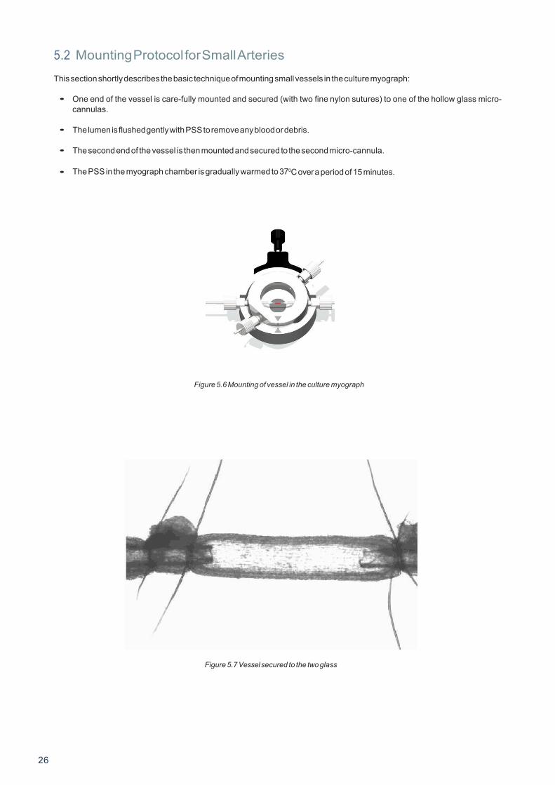
5.2 Mounting Protocol for Small Arteries This section shortly describes the basic technique of mounting small vessels in the culture myograph:
• One end of the vessel is care-fully mounted and secured (with two fine nylon sutures) to one of the hollow glass micro-
cannulas.
• The lumen is flushed gently with PSS to remove any blood or debris.
• The second end of the vessel is then mounted and secured to the second micro-cannula.
• The PSS in the myograph chamber is gradually warmed to 370C over a period of 15 minutes.
Figure 5.6 Mounting of vessel in the culture myograph
Figure 5.7 Vessel secured to the two glass 26

5.3 Buffer Recipes Physiological Saline Solution (PSS)
1x PSS:
Chemical Mol.Wt mM g/0.5L g/L g/2L g/4L NaCl (58.45) 130 3.799 7.598 15.20 30.39 KCl (74.557) 4.7 0.175 0.35 0.70 1.40 KH2PO4 (136.09) 1.18 0.08 0.16 0.32 0.64 MgSO4 7H2O (246.498) 1.17 0.145 0.29 0.58 1.16 NaHCO3 (84.01) 14.9 0.625 1.25 2.50 5.00 Glucose (180.16) 5.5 0.5 1.00 2.00 4.00 EDTA (380) 0.026 0.005 0.01 0.02 0.04 CaCl2 (110.99) 1.16 0.8ml 1.6ml 3.2ml 6.4ml
(1.0 M solution)
1. Make a 1.0M solution of CaCl2 (110.99) in double-distilled H O. Filter-sterilize the calcium solution through a 0.22 μm filter. The sterilized solution can be stored in the refrigerator for up to 3 months.
2. Dissolve all the chemicals except the CaCl2 in approximately 80% of the desired final volume of double distilled H2O while
being constantly stirred. For example, if 1 litre of PSS is to be made, then dissolve all the chemicals in 800ml of double distilled H2O.
3. Add the appropriate volume of 1.0M CaCl2 for the total volume of PSS being made (for example, 1.6ml of 1.0M CaCl2 for 1
litre of buffer). Continue to stir the PSS while the CaCl2 is being added.
4. Bring the solution up to the final volume with double-distilled H2O. Continue to stir the solution until the EDTA is fully dissolved. This takes about 15 minutes at room temperature.
5. Aerate the solution with carbogen for about 20 minutes.
25x Concentrated PSS:
Chemical Mol.Wt mM g/0.5L g/L g/2L g/4L NaCl (58.45) 3250 94.98 189.96 379.92 759.84 KCl (74.557) 117.5 4.375 8.75 17.5 35.0 KH2PO4 (136.09) 29.5 2.0 4.0 8.0 16.0
MgSO4 7H2O (246.498) 29.25 3.625 7.25 14.5 29.0 NaHCO3 (84.01) 14.9 0.625 1.25 2.50 5.00 Glucose (180.16) 5.5 0.5 1.00 2.00 4.00 EDTA (380) 0.65 0.125 0.25 0.50 1.0 CaCl2 (110.99) 40 20ml 40ml 80ml 160ml
(1.0 M solution) 1. Make a 1.0M solution of CaCl2 (110.99) in double-distilled H O. Filter-sterilize the calcium solution through a 0.22 μm
filter. The sterilized solution can be stored in the refrigerator for up to 3 months.
2. Dissolve all the chemicals except the CaCl2 in approximately 80% of the desired final volume of double distilled H2O while being constantly stirred. For example, if 1 litre of PSS is to be made, then dissolve all the chemicals in 800ml of double distilled H2O
27

3. Add the appropriate volume of 1.0M CaCl2for the total volume of PSS being made (for example, 1.6ml of 1.0M CaCl2 for 1 liter of buffer) Continue to stir the PSS while the CaCl2 is being added.
4. Bring the solution up to the final volume with double-distilled H2 O. Continue to stir the solution until the EDTA is fully
dissolved. This takes about 15 minutes at room temperature. Before use:
5. Dilute the 25 x PSS stock solution 1:25 using double distilled H2O
6. Add: 91g/L Glucose 100 g/L NaHCO3
7. Aerate the solution with carbogen (95%O2+5%CO2) for at least 20 minutes. If necessary wait further for the pH of the buffer to reach 7.4 pH.
High potassium Physiological Saline Solution (KPSS) 1x 60mM KPSS:
Chemical Mol.Wt mM g/0.5L g/L g/2L g/4L NaCl (58.45) 74.7 2.18 4.37 8.73 17.46 KCl (74.557) 60 2.24 4.47 8.95 17.89 KH2PO4 (136.09) 1.18 0.08 0.16 0.32 0.64 MgSO4 7H2O (246.498) 1.17 0.145 0.29 0.58 1.16 NaHCO3 (84.01) 14.9 0.625 1.00 2.00 5.00 Glucose (180.16) 5.5 0.5 1.00 2.00 4.00 EDTA (380) 0.026 0.005 0.01 0.02 0.04 CaCl2 (110.99) 1.6 0.8ml 1.6ml 3.2ml 6.4ml
(1.0 M solution)
1. Make a 1.0M solution of CaCl2 (110.99) in double-distilled H2O. Filter-sterilize the calcium solution through a 0.22 μm filter. The sterilized solution can be stored in the refrigerator for up to 3 months.
2. Dissolve all the chemicals except the CaCl2 in approximately 80% of the desired final volume of double distilled H2O
while being constantly stirred. For example, if 1 litre of PSS is to be made, then dissolve all the chemicals in 800ml of double distilled H2 O.
3. Add the appropriate volume of 1.0M CaCl2 for the total volume of PSS being made (for example, 1.6ml of 1.0M CaCl2 for 1
litre of buffer). Continue to stir the PSS while the CaCl2 is being added.
4. Bring the solution up to the final volume with double-distilled H2O. Continue to stir the solution until the EDTA is fully dissolved. This takes about 15 minutes at room temperature.
5. Aerate the solution with carbogen (95% O2 + 5% CO2 ) for about 20 minutes.
28
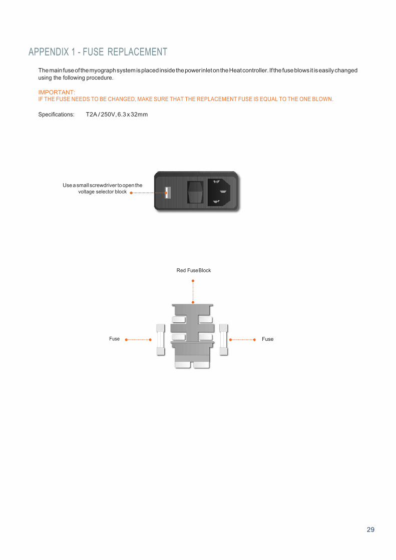
APPENDIX 1 - FUSE REPLACEMENT
The main fuse of the myograph system is placed inside the power inlet on the Heat controller. If the fuse blows it is easily changed using the following procedure.
IMPORTANT: IF THE FUSE NEEDS TO BE CHANGED, MAKE SURE THAT THE REPLACEMENT FUSE IS EQUAL TO THE ONE BLOWN.
Specifications: T2A / 250V, 6.3 x 32mm
Use a small screwdriver to open the voltage selector block
Red Fuse Block
Fuse Fuse
29

APPENDIX 2 - SYSTEM SPECIFICATIONS
Technical specifications - Culture Myograph – 204CM Chamber Unit Vessel size: >60 μm Chamber: Four Chamber volume: Max. 2 ml Cannula ports: OD 1.2mm Superfusion ports: Built-in Base window: 10mm diameter type II coverslip Chamber material: Acid-resistant stainless steel Chamber cover: Removable with gasket and access port
Chamber Stage Alignment: Two cannula holders Adjustment : X, Y & Z Flow: 25 ml bottles for flow adjustment Temp. range : Ambient temp - 50°C Temp. control: Via MyoView Temp. probe: Included
Microscope Stand Camera: USB ½” B/W CCD Objective: 10x Adjustment: X, Y & Z directions Light source: Infrared LED Voltage: 100 to 240 VAC (auto) 50/60 Hz
Pressure Regulator Pressure range: 0 - 300 mmHg Pressure source: Atmospheric pressure
Heat controller Temperature range: Max 50°C
Pump Peristaltic pump: 2.5 - 50 rpm (for superfusion of the chamber) 4-8 channel versions available
Optional accessories
FlowMeter - 162FM - range: 15 μl/min to 4000 μl/min
30
