2021 (2) walls: external insulation on solid masonry
TRANSCRIPT

2021
INTRODUCTION
The details in this section have been developed for a range of externally insulated single leaf masonry/hollow block wall constructions. The Introduction document "Limiting Thermal Bridging and Air Infiltration Acceptable Construction Details" provides practical information with regards to implementation of these details onsite. This guide should be read in conjunction with these details. Details are given for the junctions with a range of roof, ground floor and internal floor types, as well as at external wall opes.
The details are indicative. They focus on the issues of thermal performance and air tightness. Other issues are not considered fully. Insulation thicknesses for the main building elements have not been provided, as these depend on the thermal properties of the materials chosen, as well as on the desired U-value.
Masonry materials shown on the drawings are blocks and bricks. Other masonry materials, including precast and insitu concrete, may be substituted without loss of thermal performance or increased technical risk. The use of thermally resistant materials, beyond that depicted, will naturally increase the thermal performance of the building fabric.
All materials and workmanship are to be installed to Technical Guidance Document D "Materials and Workmanship."
All details are shown with a thin coat render system for simplification. However, a range of cladding may be used without any loss of thermal performance. All external cladding systems should be proper materials as defined in Part D. It is recommended that insulating and cladding components
are part of a system to ensure compatibility.
These diagrams illustrate good practice for design and construction of interfaces only in respect to ensuring thermal performance and air barrier continuity. The guidance must be implemented with due regard to all other requirements imposed by the Building Regulations.
Where these construction details are used for the Target U-values provided in the Appendix D, Table D2 of TGD L 2021 the psi values published in Table D2 may be used to calculate the actual Thermal Bridging heat loss for a dwelling for key thermal bridging junctions in that dwelling.
Technical Guidance Document B and Supplementary Guidance to TGD B provides guidance in relation to the provision of cavity barriers in air cavities, cavity barriers within combustible insulation layers and fire protection of structural elements.
The 2021 edition of the ACDs updates the drawings to take account of industry practice. The performance requirements remain the same as for the 2011 edition.
(2) WALLS: EXTERNAL INSULATION ON SOLID MASONRY / HOLLOW BLOCK WALLS

2021
This is an externally supported balcony (the balcony slab is
not a continuation of the floorslab) where the wall insulation
is continuous and not bridged by the balcony slab.
Value of Ψ is applied to each dwelling.
Where two building elements have one U-value above its
target while the other is below its target U-value, the
aggregate percentage change from the respective target
U-values in the table should not exceed +20% for the Psi (ψ)
value to be valid, i.e. if for the 0.15 U-value wall, if the U-value
was increased by 10% above the wall target U-value (from 0.15
to 0.165), then the roof U-value could be at most 10% below
the roof target U-value (from 0.14 to 0.126), because the
aggregate change would then be 20%.
ψ values for a Target U-value for the wall of 0.15 W/m²K can be
used for a range of U-values from of 0.12 W/m²K to 0.17
W/m²K for the construction type specified. The U-values of the
flanking elements to the wall can vary from the flanking element
target U-value as follows: Pitched roof insulation on slope,
insulation on ceiling 0.11 to 0.16 W/m²K; Flat Roof = 0.11 to
0.17 W/m²K; Ground Floor = 0.12 to 0.18 W/m²K
ψ values for a Target U-value for the wall of 0.18 W/m²K for the construction type specified. The U-values of the flanking
elements to the wall can vary from the flanking element target
U-value as follows: Pitched roof insulation on slope, insulation
on ceiling = 0.13 to 0.16 W/m²K; Flat Roof = 0.16 to 0.2
W/m²K; Ground Floor = 0.16 to 0.21 W/m²K.
1.
2.
3.
4.
5.
Psi value is for whole junction. Half the value should be
applied to each dwelling on either side of the junction
6.
Table D2 Section 2 - External Insulation
Junction detail
Identifier
Section 2
2.01
2.01a
2.02
2.02a
2.03
2.03a
2.04
2.04a
2.05
2.06
2.07
2.08/2.09
2.10.1/2.11.1
2.12.1
2.12.2
2.13
2.14
2.15/2.16
2.17
2.18
2.19
2.20
2.21
2.22
2.23.1
2.23.2
Section G
G.01.1
G.01.2
G.05.1
G.05.2
Other Details
2.B.1
2.B.2
Details
Ground Floor - Insulation above slab
Ground Floor - Insulation above slab
Ground Floor - Insulation below slab
Ground Floor - Insulation below slab
Timber Suspended Ground Floor
Timber Suspended Ground Floor
Concrete Intermediate Floor within a dwelling
Concrete Separating Floor between dwellings
6
Masonry Separating Wall - plan
6
Masonry Partition Wall
Stud Partition Wall
Eaves – Unventilated/Ventilated roof space
Eaves – Unventilated/Ventilated - Insulation between and under rafters –
Dormer
Eaves - Unventilated - Insulation between and over rafters - Pitched ceiling
Eaves – Unventilated/Ventilated - Insulation between and under rafters -
Pitched with flat ceiling
Eaves - Unventilated - Insulation between and over rafters
Ventilated Roof - Attic floor level
Gable - Insulation between and under rafters – Unventilated/Ventilated rafter
void
Gable - Insulation between and over rafters - Unventilated rafter void
Flat Roof - Eaves
Flat Roof - Parapet
Ope - Lintel
Ope - Jamb
Sill
Corner
Inverted corner
General Details
Masonry Separating Wall Head – Section
6
Masonry Separating Wall Head – Section
6
Solid Masonry Separating Wall through ground floor
6
Solid Masonry (narrow) Partition Wall through ground floor
Balcony within dwelling
4
Balcony between dwellings
4, 5
0.131
0.214
0.162
0.235
0.158
0.297
0.001
0.071
0.049
0.000
0.000
0.067
0.050
0.016
0.020
0.013
0.347
0.091
0.131
0.046
0.349
0.097
0.088
0.149
0.099
-0.141
0.511
0.488
0.201
0.138
0.000
0.020
0.145
0.259
0.172
0.247
0.204
0.368
0.000
0.048
0.033
0.000
0.000
0.074
0.055
0.031
0.017
0.027
0.335
0.087
0.106
0.045
0.327
0.098
0.091
0.109
0.070
-0.096
0.484
0.458
0.240
0.150
0.000
0.020
Junction detail
Target U-values
U-value = 0.18
Wm²K
1, 3
(roof U = 0.16)
(floor U = 0.18)
U-value = 0.15
Wm²K
2, 3
(roof U = 0.14)
(floor U = 0.15)
ψ-value (W/mK) ψ-value (W/mK)
(2) WALLS: EXTERNAL INSULATION ON SOLID MASONRY / HOLLOW BLOCK WALLS

Ground Floor - Insulation Above Slab
with Lightweight Block
Floor insulation to tightly abut
blockwork wall
Ensure wall insulation is installed at
least 300 mm below finished floor
level
Material on top of floor insulation can be screed or floating floor
Wall insulation installed below the wall DPC must be fit for purpose with
regards to water absorption
THERMAL PERFORMANCE
Ensure block with a maximum
Thermal Conductivity of 0.20 W/mK
in the direction of heat flow is used
and that block is suitable for use in
foundations
AIR BARRIER - OPTIONS
(2) WALLS: EXTERNAL INSULATION ON
SOLID MASONRY/HOLLOW BLOCK
GENERAL NOTES
OPTION
(TICK ONE)
(TICK ALL)
CHECKLIST
(TICK ALL)
30
0 m
m m
in
.
Seal all penetrations through air
barrier with suitable air tightness
tape, grommets or flexible sealant
Seal between wall and floor air
barriers with suitable airtightness
tape or a flexible sealant
DETAIL 2.01, 2021
AIR BARRIER - CONTINUITY
CHECKLIST
Refer to Technical Guidance Document Part C for details on radon protection
Wet-finish plaster coat, or
Masonry wall with scratch coat, and finished with plasterboard, or
Airtightness membrane and tapes
Plasterboard on dabs or battens, with continuous ribbon of
adhesive around all openings, along top and bottom of wall and
at internal and external corners
Complying with checklist will help achieve design air
permeability
Install perimeter insulation with a
minimum R-value of 1.1 m²K/W

Ground Floor - Insulation Above Slab
Wall insulation installed below the wall DPC must be fit for purpose with
regards to water absorption
Material on top of floor insulation can be screed or floating floor
Ensure wall insulation is installed at
least 430 mm below ground level with
a minimum R-value of 4.0 m²K/W
Floor insulation to tightly abut
blockwork wall
THERMAL PERFORMANCE
AIR BARRIER - OPTIONSGENERAL NOTES
(TICK ALL)
CHECKLIST
(TICK ALL)
OPTION
(TICK ONE)
43
0 m
m m
in
.
DETAIL 2.01a, 2021
AIR BARRIER - CONTINUITY
CHECKLIST
Seal all penetrations through air
barrier with suitable air tightness
tape, grommets or flexible sealant
Seal between wall and floor air
barriers with suitable airtightness
tape or a flexible sealant
Refer to Technical Guidance Document Part C for details on radon protection
(2) WALLS: EXTERNAL INSULATION ON
SOLID MASONRY/HOLLOW BLOCK
Wet-finish plaster coat, or
Masonry wall with scratch coat, and finished with plasterboard, or
Airtightness membrane and tapes
Plasterboard on dabs or battens, with continuous ribbon of
adhesive around all openings, along top and bottom of wall and
at internal and external corners
15
0 m
m m
in
.
Complying with checklist will help achieve design air
permeability
Install perimeter insulation with a
minimum R-value of 1.1 m²K/W

Wall insulation installed below the wall DPC must be fit for purpose with
regards to water absorption
Ensure wall insulation is installed at
least 300 mm below finished floor
level
Ground Floor - Insulation Below Slab
with Lightweight Block
Floor insulation to tightly abut
blockwork wall
Ensure block with a maximum
Thermal Conductivity of 0.20 W/mK
in the direction of heat flow is used
and that block is suitable for use in
foundations
GENERAL NOTES
THERMAL PERFORMANCE
AIR BARRIER - OPTIONS
(TICK ALL)
CHECKLIST
(TICK ALL)
OPTION
(TICK ONE)
Install perimeter insulation with a
minimum R-value of 1.1 m²K/W
DETAIL 2.02, 2021
AIR BARRIER - CONTINUITY
CHECKLIST
Seal all penetrations through air
barrier with suitable air tightness
tape, grommets or flexible sealant
Seal between wall and floor air
barriers with suitable airtightness
tape or a flexible sealant
30
0 m
m m
in
.
Refer to Technical Guidance Document Part C for details on radon protection
(2) WALLS: EXTERNAL INSULATION ON
SOLID MASONRY/HOLLOW BLOCK
Wet-finish plaster coat, or
Masonry wall with scratch coat, and finished with plasterboard, or
Airtightness membrane and tapes
Plasterboard on dabs or battens, with continuous ribbon of
adhesive around all openings, along top and bottom of wall and
at internal and external corners
Complying with checklist will help achieve design air
permeability

Wall insulation installed below the wall DPC must be fit for purpose with
regards to water absorption
Ground Floor - Insulation Below Slab
Floor insulation to tightly abut
blockwork wall
Ensure wall insulation is installed at
least 430 mm below ground level
R-value 4.0 m²K/W
AIR BARRIER - OPTIONS
THERMAL PERFORMANCE
GENERAL NOTES
(TICK ALL)
CHECKLIST
(TICK ALL)
OPTION
(TICK ONE)
Install perimeter insulation with a
Min. R-value of 1.1 m²K/W
DETAIL 2.02a, 2021
AIR BARRIER - CONTINUITY
CHECKLIST
Seal all penetrations through air
barrier with suitable air tightness
tape, grommets or flexible sealant
Seal between wall and floor air
barriers with suitable airtightness
tape or a flexible sealant
43
0 m
m m
in
.
(2) WALLS: EXTERNAL INSULATION ON
SOLID MASONRY/HOLLOW BLOCK
Wet-finish plaster coat, or
Masonry wall with scratch coat, and finished with plasterboard, or
Airtightness membrane and tapes
Plasterboard on dabs or battens, with continuous ribbon of
adhesive around all openings, along top and bottom of wall and
at internal and external corners
15
0 m
m m
in
.
Refer to Technical Guidance Document Part C for details on radon
protection
Complying with checklist will help achieve design air
permeability

Timber Suspended Ground Floor
with Lightweight Block
Support joists on tassel walls to avoid building into external walls
Seal joints in timber floor with
suitable glue. Fully support and fix
any square edge joints in the decking
to the joists
Ensure wall insulation is installed at
least 200 mm below top of floor
insulation
Pack gap between floor joist and
blockwork wall with compressible
insulation with a minimum R-value
of 0.63 m²K/W
Ensure insulation is in contact with
underside of timber flooring. Fix with
netting, breather membrane or
retaining batten below floor insulation
Ensure block with a maximum
Thermal Conductivity of 0.20 W/mK
in the direction of heat flow is used
and that block is suitable for use in
foundations
AIR BARRIER - OPTIONS
THERMAL PERFORMANCE
GENERAL NOTES
(TICK ALL)
CHECKLIST
(TICK ALL)
OPTION
(TICK ONE)
200 m
m m
in.
DETAIL 2.03, 2021
AIR BARRIER - CONTINUITY
CHECKLIST
(2) WALLS: EXTERNAL INSULATION ON
SOLID MASONRY/HOLLOW BLOCK
Seal between wall and floor air
barriers with suitable airtightness
tape or a flexible sealant
Seal all penetrations through air
barrier with suitable air tightness
tape, grommets or flexible sealant
Wet-finish plaster coat, or
Masonry wall with scratch coat, and finished with plasterboard, or
Airtightness membrane and tapes
Plasterboard on dabs or battens, with continuous ribbon of
adhesive around all openings, along top and bottom of wall and
at internal and external corners
Refer to Technical Guidance Document Part C for details on sub-floor
ventilation
Complying with checklist will help achieve design air
permeability

Timber Suspended Ground Floor
AIR BARRIER - OPTIONS
THERMAL PERFORMANCE
GENERAL NOTES
(TICK ALL)
CHECKLIST
(TICK ALL)
OPTION
(TICK ONE)
Ensure wall insulation is installed at
least 750 mm below top of floor
insulation
Pack gap between floor joist and
blockwork wall with compressible
insulation with a minimum R-value
of 0.63 m²K/W
75
0 m
m m
in
.
DETAIL 2.03a, 2021
AIR BARRIER - CONTINUITY
CHECKLIST
(2) WALLS: EXTERNAL INSULATION ON
SOLID MASONRY/HOLLOW BLOCK
Support joists on tassel walls to avoid building into external walls
Seal joints in timber floor with
suitable glue. Fully support and fix
any square edge joints in the decking
to the joists
Seal between wall and floor air
barriers with suitable airtightness
tape or a flexible sealant
Seal all penetrations through air
barrier with suitable air tightness
tape, grommets or flexible sealant
Wet-finish plaster coat, or
Masonry wall with scratch coat, and finished with plasterboard, or
Airtightness membrane and tapes
Plasterboard on dabs or battens, with continuous ribbon of
adhesive around all openings, along top and bottom of wall and
at internal and external corners
Wall insulation installed below the wall DPC must be fit for purpose with
regards to water absorption
Refer to Technical Guidance Document Part C for details on sub-floor
ventilation
Ensure insulation is in contact with
underside of timber flooring. Fix with
netting, breather membrane or
retaining batten below floor insulation
Complying with checklist will help achieve design air
permeability

Concrete Intermediate Floor Within a Dwelling
AIR BARRIER - OPTIONS
THERMAL PERFORMANCE
GENERAL NOTES
DETAIL 2.03, 2021
AIR BARRIER - CONTINUITY
CHECKLIST
(TICK ALL)
CHECKLIST
(TICK ALL)
OPTION
(TICK ONE)
Continue external wall insulation
across floor abutment zone
(2) WALLS: EXTERNAL INSULATION ON
SOLID MASONRY/HOLLOW BLOCK
Seal between the wall air barrier and
the top and underside of the floor
slab with suitable airtightness tape
or a flexible sealant. (Dotted blue
line is notional, to depict the air
barrier continuity through floor
zone)
Ensure continuous mortar bed
between floor slab and top of
blockwork wall
Seal all penetrations through air
barrier with suitable air tightness
tape, grommets or flexible sealant
Wet-finish plaster coat, or
Masonry wall with scratch coat, and finished with plasterboard, or
Airtightness membrane and tapes
Plasterboard on dabs or battens, with continuous ribbon of
adhesive around all openings, along top and bottom of wall and
at internal and external corners
Complying with checklist will help achieve design air
permeability

Concrete Separating Floor Between Dwellings DETAIL 2.04a, 2021
AIR BARRIER - CONTINUITY
AIR BARRIER - OPTIONS
THERMAL PERFORMANCE
GENERAL NOTES
CHECKLIST
(TICK ALL)
CHECKLIST
(TICK ALL)
OPTION
(TICK ONE)
Continue external wall insulation
across floor abutment zone. (Use
appropriate material where cavity
barrier is required)
(2) WALLS: EXTERNAL INSULATION ON
SOLID MASONRY/HOLLOW BLOCK
Seal between the wall air barrier and
the top and underside of the floor
slab with suitable airtightness tape
or a flexible sealant. (Dotted blue
line is notional, to depict the air
barrier continuity through floor
zone)
Ensure continuous mortar bed
between floor slab and top of
blockwork wall
Seal all penetrations through air
barrier with suitable air tightness
tape, grommets or flexible sealant
Refer to Technical Guidance Document E for guidance on sound insulation
Wet-finish plaster coat, or
Masonry wall with scratch coat, and finished with plasterboard, or
Airtightness membrane and tapes
Plasterboard on dabs or battens, with continuous ribbon of
adhesive around all openings, along top and bottom of wall and
at internal and external corners
Refer to Technical Guidance Document B for guidance on cavity barriers

Masonry Separating Wall - Plan
AIR BARRIER - OPTIONS
THERMAL PERFORMANCE
GENERAL NOTES
DETAIL 2.05, 2021
AIR BARRIER - CONTINUITY
CHECKLIST
(TICK ALL)
CHECKLIST
(TICK ALL)
OPTION
(TICK ONE)
(2) WALLS: EXTERNAL INSULATION ON
SOLID MASONRY/HOLLOW BLOCK
Seal all penetrations through air
barrier with suitable air tightness
tape, grommets or flexible sealant
Refer to Technical Guidance Document E for guidance on sound insulation
Refer to Technical Guidance Document B for guidance on cavity barriers
Continue external wall insulation
across abutment zone. (Use
appropriate material where cavity
barrier is required)
Read this detail in conjunction with G.01, Masonry Separating Wall Head
Wet-finish plaster coat, or
Masonry wall with scratch coat, and finished with plasterboard, or
Airtightness membrane and tapes
Plasterboard on dabs or battens, with continuous ribbon of
adhesive around all openings, along top and bottom of wall and
at internal and external corners
Complying with checklist will help achieve design air
permeability

Masonry Partition Wall
AIR BARRIER - OPTIONS
THERMAL PERFORMANCE
GENERAL NOTES
DETAIL 2.06, 2021
AIR BARRIER - CONTINUITY
CHECKLIST
(TICK ALL)
CHECKLIST
(TICK ALL)
OPTION
(TICK ONE)
Continue external wall insulation
across abutment zone
(2) WALLS: EXTERNAL INSULATION ON
SOLID MASONRY/HOLLOW BLOCK
Seal between air barrier on external
wall and the blockwork, to the
partition wall with suitable
airtightness tape. (Dotted blue line is
notional, to depict air barrier
continuity through partition,
depending on whether partition
toothed into external wall or braced
with ties)
Seal all penetrations through air
barrier with suitable air tightness
tape, grommets or flexible sealant
Read this detail in conjunction with G.02, Blockwork Partition Head
Wet-finish plaster coat, or
Masonry wall with scratch coat, and finished with plasterboard, or
Airtightness membrane and tapes
Plasterboard on dabs or battens, with continuous ribbon of
adhesive around all openings, along top and bottom of wall and
at internal and external corners
Complying with checklist will help achieve design air
permeability

Stud Partition Wall
AIR BARRIER - OPTIONS
THERMAL PERFORMANCE
GENERAL NOTES
DETAIL 2.07, 2021
AIR BARRIER - CONTINUITY
CHECKLIST
(TICK ALL)
CHECKLIST
(TICK ALL)
OPTION
(TICK ONE)
(2) WALLS: EXTERNAL INSULATION ON
SOLID MASONRY/HOLLOW BLOCK
Install external air barrier before
stud; or install barrier before
partition lining and seal all gaps
between air barrier and stud with
with suitable airtightness tape.
(Dotted blue line depicts air barrier
continuity through partition stud
member)
Seal all penetrations through air
barrier with suitable air tightness
tape, grommets or flexible sealant
Continue external wall insulation
across abutment zone
Read this detail in conjunction with G.03, Timber Stud Partition Head, or
G.04, Metal Stud Partition Head as appropriate
Wet-finish plaster coat, or
Masonry wall with scratch coat, and finished with plasterboard, or
Airtightness membrane and tapes
Plasterboard on dabs or battens, with continuous ribbon of
adhesive around all openings, along top and bottom of wall and
at internal and external corners
Complying with checklist will help achieve design air
permeability

CHECKLIST
(TICK ALL)
Ensure continuity of insulation
throughout junction
Use of over joist insulation eliminates the cold bridge caused by the joist
Ensure full depth of insulation
between and over joists abuts
eaves insulation
Ensure gap between wall plate and
vapour permeable underlay is
completely filled with insulation
having a minimum R-value across the
insulation thickness of 4.30 m²K/W
Use vapour permeable roof underlay in accordance with third party
certification
Read this detail in conjunction with 2.14, Gable at Attic Floor Level
Eaves insulation must not hinder free water drainage below the tiling
battens
AIR BARRIER - OPTIONS
THERMAL PERFORMANCE
Eaves - Unventilated Attic
(TICK ALL)
OPTION
(TICK ONE)
Seal between wall and ceiling air
barriers with suitable air tightness
tape or a flexible sealant
Seal all penetrations through air
barriers with suitable air tightness
tape, grommets or a flexible
sealant
DETAIL 2.08, 2021
AIR BARRIER - CONTINUITY
CHECKLIST
(2) WALLS: EXTERNAL INSULATION ON
SOLID MASONRY/HOLLOW BLOCK
GENERAL NOTES
Wet-finish plaster coat, or
Masonry wall with scratch coat, and finished with plasterboard, or
Airtightness membrane and tapes
Plasterboard on dabs or battens, with continuous ribbon of
adhesive around all openings, along top and bottom of wall and
at internal and external corners
Refer to Technical Guidance Document B and Supplementary Guidance to
TGD B for guidance on cavity barriers and fire protection of structures
Complying with checklist will help achieve design air
permeability
Note: Detail is indicative for thermal
purposes. Where continuity of insulation is
maintained throughout the junction,
alternative structural design may be used.

AIR BARRIER - OPTIONS
THERMAL PERFORMANCE
(TICK ALL)
CHECKLIST
(TICK ALL)
OPTION
(TICK ONE)
Eaves - Ventilated AtticDETAIL 2.09, 2021
AIR BARRIER - CONTINUITY
CHECKLIST
(2) WALLS: EXTERNAL INSULATION ON
SOLID MASONRY/HOLLOW BLOCK
GENERAL NOTES
Thermal performance of junction can be improved by incorporating an eaves wind
barrier (plywood, OSB, softboard or other suitable material)
Use of over joist insulation eliminates the cold bridge caused by the joist
Use a proprietary eaves ventilator to ensure ventilation in accordance with
Technical Guidance Document F. Installation of the eaves ventilator must not
prevent free water drainage below the tiling battens
Read this detail in conjunction with detail 2.14, Gable at Attic Floor Level
Seal between wall and ceiling air
barriers with suitable air tightness
tape or a flexible sealant
Seal all penetrations through air
barriers with suitable air tightness
tape, grommets or a flexible
sealant
Ensure continuity of insulation
throughout junction
Ensure full depth of insulation
between and over joists abuts
eaves insulation
Ensure gap between wall plate and
proprietary eaves vent is completely
filled with insulation having a
minimum R-value across the
insulation thickness of 4.30 m²K/W
Wet-finish plaster coat, or
Masonry wall with scratch coat, and finished with plasterboard, or
Airtightness membrane and tapes
Plasterboard on dabs or battens, with continuous ribbon of
adhesive around all openings, along top and bottom of wall and
at internal and external corners
Complying with checklist will help achieve design air
permeability
Refer to Technical Guidance Document B and Supplementary Guidance to TGD B
for guidance on cavity barriers and fire protection of structures

Eaves - Insulation Between and Under Rafters
- Unventilated Rafter Void - Dormer
AIR BARRIER - OPTIONS
THERMAL PERFORMANCE
GENERAL NOTES
DETAIL 2.10.1, 2021
AIR BARRIER - CONTINUITY
CHECKLIST
(TICK ALL)
CHECKLIST
(TICK ALL)
OPTION
(TICK ONE)
Complying with checklist will help achieve design air
permeability
(2) WALLS: EXTERNAL INSULATION ON
SOLID MASONRY/HOLLOW BLOCK
Full-depth nogging installed between
ceiling joists to carry air barrier
through ceiling zone, sealed to air
barrier in roof with flexible sealant
or airtight tape
Seal between ceiling and wall air
barriers with, suitable airtightness
tape or flexible sealant
Seal all penetrations through air
barrier with suitable air tightness
tape, grommets or flexible sealant
Vapour permeable roof underlay to be used in accordance with approved third party
certification
Use of over joist and under rafter insulation eliminates the cold bridge caused by the
joist/rafter
Read this detail in conjunction with detail 2.15, Gable - Unventilated Rafter Void
Installation of the eaves insulation must not prevent free water drainage below the tiling
battens
Refer to Technical Guidance Document B and Supplementary Guidance to TGD B for
guidance on cavity barriers and fire protection of structures
An effective vapour control layer, which may serve as an air barrier, should be provided on
the warm side of the insulation in accordance with Appendix B of Technical Guidance
Document L
Ensure continuity of insulation
throughout junction
Ensure full depth of insulation
between and over joists abuts eaves
insulation
Ensure insulation is installed tightly
between rafters and is in contact
with under-rafter insulation
Ensure gap between wall plate and
vapour permeable underlay is
completely filled with insulation having
a minimum R-value across the
insulation thickness of 4.30 m²K/W
Wet-finish plaster coat, or
Plasterboard on dabs or battens, with continuous ribbon of
adhesive around all openings, along top and bottom of wall and at
internal and external corners
Masonry wall with scratch coat, and finished with plasterboard, or
Airtightness membrane and tapes
2.10.1

Eaves - Insulation Between and Under Rafters -
Ventilated Rafter Void - Dormer
AIR BARRIER - OPTIONS
THERMAL PERFORMANCE
GENERAL NOTES
(TICK ALL)
CHECKLIST
(TICK ALL)
OPTION
(TICK ONE)
Complying with checklist will help achieve design air
permeability
DETAIL 2.11.1, 2021
AIR BARRIER - CONTINUITY
CHECKLIST
(2) WALLS: EXTERNAL INSULATION ON
SOLID MASONRY/HOLLOW BLOCK
Ensure continuity of insulation
throughout junction
Ensure insulation is installed tightly
between rafters and is in contact
with under-rafter insulation
Ensure gap between wall plate and
proprietary eaves vent is completely
filled with insulation having a
minimum R-value across the
insulation thickness of 4.30 m²K/W
Thermal performance of junction can be improved by incorporating an eaves wind barrier
(plywood, OSB, softboard or other suitable material)
Use a proprietary eaves ventilator to ensure ventilation in accordance with Technical
Guidance Document F. Installation of the eaves ventilator must not prevent free water
drainage below the tiling battens
Use of over joist and under rafter insulation eliminates the cold bridge caused by the
joist/rafter
Read this detail in conjunction with detail 2.16 Gable - Ventilated Rafter Void
Refer to Technical Guidance Document B and Supplementary Guidance to TGD B for
guidance on cavity barriers and fire protection of structures
Full-depth nogging installed between
ceiling joists to carry air barrier
through ceiling zone, sealed to air
barrier in roof with flexible sealant
or airtight tape
Seal between ceiling and wall air
barriers with, suitable airtightness
tape or flexible sealant
Seal all penetrations through air
barrier with suitable air tightness
tape, grommets or flexible sealant
An effective vapour control layer, which may serve as an air barrier, should be provided on
the warm side of the insulation in accordance with Appendix B of Technical Guidance
Document L
Wet-finish plaster coat, or
Plasterboard on dabs or battens, with continuous ribbon of
adhesive around all openings, along top and bottom of wall and at
internal and external corners
Masonry wall with scratch coat, and finished with plasterboard, or
Airtightness membrane and tapes
2.11.1

Eaves - Insulation Between and Under Rafters -
Ventilated Rafter Void - Pitched Ceiling
AIR BARRIER - OPTIONS
THERMAL PERFORMANCE
GENERAL NOTES
(TICK ALL)
CHECKLIST
(TICK ALL)
OPTION
(TICK ONE)
Complying with checklist will help achieve design air
permeability
DETAIL 2.12.1+ 2.12.2, 2021
AIR BARRIER - CONTINUITY
CHECKLIST
2.12.1
2.12.2
(2) WALLS: EXTERNAL INSULATION ON
SOLID MASONRY/HOLLOW BLOCK
Seal between wall and ceiling air
barriers with suitable air tightness
tape or a flexible sealant
Seal all penetrations through air
barriers with suitable air tightness
tape, grommets or a flexible sealant
Ensure continuity of insulation
throughout junction
Ensure insulation is installed tightly
between rafters and is in contact
with under-rafter insulation
Ensure gap between wall plate and
proprietary eaves vent is completely
filled with insulation having a
minimum R-value across the
insulation thickness of 4.30 m²K/W
Thermal performance of junction can be improved by incorporating an eaves wind barrier
(plywood, OSB, softboard or other suitable material)
Use a proprietary eaves ventilator to ensure ventilation in accordance with Technical
Guidance Document F. Installation of the eaves ventilator must not prevent free water
drainage below the tiling battens
Use of over joist and under rafter insulation eliminates the cold bridge caused by the
joist/rafter
Read this detail in conjunction with detail 2.16, Gable - Ventilated Rafter Void
An effective vapour control layer, which may serve as an air barrier, should be provided on
the warm side of the insulation in accordance with Appendix B of Technical Guidance
Document L
Refer to Technical Guidance Document B and Supplementary Guidance to TGD B for
guidance on cavity barriers and fire protection of structures
Wet-finish plaster coat, or
Plasterboard on dabs or battens, with continuous ribbon of
adhesive around all openings, along top and bottom of wall and at
internal and external corners
Masonry wall with scratch coat, and finished with plasterboard, or
Airtightness membrane and tapes

Ensure continuity of insulation
throughout junction
Ensure full depth of insulation
between and over joists abuts eaves
insulation
Ensure insulation is installed tightly
between rafters and is in contact
with under-rafter insulation
Eaves - Insulation Between and Over Rafters -
Unventilated Rafter Void - Dormer
Read this detail in conjunction with detail 2.17, Gable - Insulation Between
and Over Rafters
AIR BARRIER - OPTIONS
THERMAL PERFORMANCE
(2) WALLS: EXTERNAL INSULATION ON
SOLID MASONRY/HOLLOW BLOCK
GENERAL NOTES
(TICK ALL)
CHECKLIST
(TICK ALL)
OPTION
(TICK ONE)
Complying with checklist will help achieve design air
permeability
DETAIL 2.13, 2021
AIR BARRIER - CONTINUITY
CHECKLIST
Ensure gap between wall plate and
vapour permeable underlay is
completely filled with insulation
having a minimum R-value across the
insulation thickness of 4.30 m²K/W
Seal all penetrations through air
barrier with suitable air tightness
tape, grommets or flexible sealant
Seal between ceiling and masonry
wall air barriers with suitable
airtightness tape or flexible sealant
Nogging installed between ceiling
joists to carry air barrier through
ceiling zone, sealed to air barrier in
roof with flexible sealant or airtight
tape
Vapour permeable roof underlay to be used in accordance with
approved third party certification
Use of over rafter insulation eliminates the cold bridge caused by the rafter
Refer to Technical Guidance Document B and Supplementary Guidance to
TGD B for guidance on cavity barriers and fire protection of structures
An effective vapour control layer, which may serve as an air barrier, should
be provided on the warm side of the insulation in accordance with Appendix
B of Technical Guidance Document L
Wet-finish plaster coat, or
Plasterboard on dabs or battens, with continuous ribbon of
adhesive around all openings, along top and bottom of wall and at
internal and external corners
Masonry wall with scratch coat, and finished with plasterboard, or
Airtightness membrane and tapes

Ventilated Roof - Attic Floor Level
Read this detail in conjunction with details 2-08, Eaves - Ventilated Attic, or 2-09,
Eaves - Unventilated Attic, as appropriate
Ensure full depth of insulation
between and over joists extends to
inner face of wall
Pack compressible insulation between
last truss or joist, and gable wall with
a minimum R-value across the
insulation thickness of 1.25 m²K/W
Continue wall insulation to at least 1
metre above ceiling level
AIR BARRIER - OPTIONS
THERMAL PERFORMANCE
GENERAL NOTES
DETAIL 2.14, 2021
AIR BARRIER - CONTINUITY
CHECKLIST
(TICK ALL)
CHECKLIST
(TICK ALL)
OPTION
(TICK ONE)
Complying with checklist will help achieve design air
permeability
(2) WALLS: EXTERNAL INSULATION ON
SOLID MASONRY/HOLLOW BLOCK
Use of over joist insulation eliminates the cold bridge caused by the joist
Thermal performance of junction can to improved significantly by running insulation
of R-value 1.5 m²K/W vertically up internal face of gable wall to a height of 450mm
above ceiling level or alternatively by using blockwork with a thermal conductivity
of ≤ 0.20 W/mK in direction of heat flow in external wall at attic floor level
Seal between wall and ceiling air
barriers with suitable air tightness
tape or a flexible sealant
Seal all penetrations through air
barriers with suitable air tightness
tape, grommets or a flexible
sealant
Wet-finish plaster coat, or
Masonry wall with scratch coat, and finished with plasterboard, or
Airtightness membrane and tapes
Plasterboard on dabs or battens, with continuous ribbon of
adhesive around all openings, along top and bottom of wall and
at internal and external corners
Refer to Technical Guidance Document B and Supplementary Guidance to TGD B
for guidance on cavity barriers and fire protection of structures

Gable - Insulation Between and Under Rafters -
Unventilated Rafter Void
Vapour permeable roof underlay in accordance with approved third party certification
Use of under-rafter insulation eliminates the cold bridge caused by the rafter
Read this detail in conjunction with detail 2-11, Eaves - Insulation Between and Under
Rafters - Unventilated Rafter Void
AIR BARRIER - OPTIONS
THERMAL PERFORMANCE
GENERAL NOTES
(TICK ALL)
CHECKLIST
(TICK ALL)
OPTION
(TICK ONE)
Complying with checklist will help achieve design air
permeability
DETAIL 2.15, 2021
AIR BARRIER - CONTINUITY
CHECKLIST
(2) WALLS: EXTERNAL INSULATION ON
SOLID MASONRY/HOLLOW BLOCK
Seal between ceiling and masonry
wall air barriers with suitable
airtightness tape or flexible sealant
Seal all penetrations through air
barrier with suitable air tightness
tape, grommets or flexible sealant
Ensure insulation is installed tightly
between rafters and is in contact with
under-rafter insulation
Ensure insulation continuity
throughout junction
Ensure top of wall is levelled with
mortar to correct pitch, and that wall
insulation is taken up level with wall
top
Fit insulation over top of wall within
gable ladder with a R-value across the
thickness of 4.35 m²K/W
Wet-finish plaster coat, or
Plasterboard on dabs or battens, with continuous ribbon of
adhesive around all openings, along top and bottom of wall and at
internal and external corners
Masonry wall with scratch coat, and finished with plasterboard, or
Airtightness membrane and tapes
An effective vapour control layer, which may serve as an air barrier, should be provided on
the warm side of the insulation in accordance with Appendix B of Technical Guidance
Document L
Refer to Technical Guidance Document B and Supplementary Guidance to TGD B for
guidance on cavity barriers and fire protection of structures

Gable - Insulation Between and Under Rafters -
Ventilated Rafter Void
Read this detail in conjunction with detail 2.10, Eaves - Ventilated Rafter Void, or 2.12, Eaves
- Ventilated Rafter Void - Pitched Ceiling, as appropriate
AIR BARRIER - OPTIONS
THERMAL PERFORMANCE
GENERAL NOTES
(TICK ALL)
CHECKLIST
(TICK ALL)
OPTION
(TICK ONE)
Complying with checklist will help achieve design air
permeability
DETAIL 2.16, 2021
AIR BARRIER - CONTINUITY
CHECKLIST
(2) WALLS: EXTERNAL INSULATION ON
SOLID MASONRY/HOLLOW BLOCK
Ensure insulation is installed tightly
between rafters and is in contact with
under-rafter insulation
Ensure insulation continuity throughout
junction
Ensure top of wall is levelled with
mortar to correct pitch, and that wall
insulation is taken up level with wall
top
Fit insulation over top of wall within
gable ladder with a minimum R-value
across the thickness of 4.35 m²K/W
Seal between ceiling and masonry
wall air barriers with suitable
airtightness tape or flexible sealant
Seal all penetrations through air
barrier with suitable air tightness
tape, grommets or flexible sealant
Use of under rafter insulation eliminates the cold bridge caused by the rafter
Wet-finish plaster coat, or
Plasterboard on dabs or battens, with continuous ribbon of
adhesive around all openings, along top and bottom of wall and at
internal and external corners
Masonry wall with scratch coat, and finished with plasterboard, or
Airtightness membrane and tapes
An effective vapour control layer, which may serve as an air barrier, should be provided on
the warm side of the insulation in accordance with Appendix B of Technical Guidance
Document L
Refer to Technical Guidance Document B and Supplementary Guidance to TGD B for
guidance on cavity barriers and fire protection of structures
Maintain 50 mm ventilated void above
top of insulation
Use a proprietary eaves ventilator to ensure ventilation in accordance with Technical
Guidance Document F. Installation of the eaves ventilator must not prevent free water
drainage below the tiling battens

Gable - Insulation Between and Over Rafters -
Unventilated Rafter Void
Read this detail in conjunction with detail 2.13, Eaves - Insulation Between and Over Rafters
Ensure top of wall is levelled with
mortar to correct pitch, and that wall
insulation is taken up level with wall
top
Ensure insulation is installed tightly
between rafters and is in contact with
over-rafter insulation
AIR BARRIER - OPTIONS
THERMAL PERFORMANCE
GENERAL NOTES
(TICK ALL)
CHECKLIST
(TICK ALL)
OPTION
(TICK ONE)
Complying with checklist will help achieve design air
permeability
DETAIL 2.17, 2021
AIR BARRIER - CONTINUITY
CHECKLIST
(2) WALLS: EXTERNAL INSULATION ON
SOLID MASONRY/HOLLOW BLOCK
Seal between ceiling and masonry
wall air barriers with suitable
airtightness tape or flexible sealant
Seal all penetrations through air
barrier with suitable air tightness
tape, grommets or flexible sealant
Ensure insulation continuity
throughout junction
Use of over rafter insulation eliminates the cold bridge caused by the rafter
Vapour permeable roof underlay to be used in accordance with approved third party
certification
Wet-finish plaster coat, or
Plasterboard on dabs or battens, with continuous ribbon of
adhesive around all openings, along top and bottom of wall and at
internal and external corners
Masonry wall with scratch coat, and finished with plasterboard, or
Airtightness membrane and tapes
An effective vapour control layer, which may serve as an air barrier, should be provided on
the warm side of the insulation in accordance with Appendix B of Technical Guidance
Document L
Refer to Technical Guidance Document B and Supplementary Guidance to TGD B for
guidance on cavity barriers and fire protection of structures
Fit insulation over top of wall within
gable ladder with a minimum R-value
across the thickness of 2.10 m²K/W

Flat Roof - Eaves
AIR BARRIER - OPTIONS
THERMAL PERFORMANCE
GENERAL NOTES
(TICK ALL)
CHECKLIST
(TICK ALL)
OPTION
(TICK ONE)
Complying with checklist will help achieve design air
permeability
DETAIL 2.18, 2021
AIR BARRIER - CONTINUITY
CHECKLIST
(2) WALLS: EXTERNAL INSULATION ON
SOLID MASONRY/HOLLOW BLOCK
Ensure full depth of over roof
insulation over joists extends to roof
edge
Ensure wall top is level and that wall
insulation is taken up level with wall
top
BS 5250:2011 + A1:2016 provides for a high performance vapour
barrier to be laid above the deck, turned up at perimeter of the
insulation and sealed to weathering membrane
Fit insulation over wall top within
roof over-hang with a minimum
R-value of 5.00 m²K/W
Fix ceiling first and seal between
ceiling and masonry wall air
barriers with suitable airtightness
tape or flexible sealant
Seal all penetrations through air
barrier with suitable air tightness
tape, grommets or flexible sealant
Wet-finish plaster coat, or
Plasterboard on dabs or battens, with continuous ribbon of
adhesive around all openings, along top and bottom of wall and at
internal and external corners
Masonry wall with scratch coat, and finished with plasterboard, or
Airtightness membrane and tapes
An effective vapour control layer, which may serve as an air barrier, should
be provided on the warm side of the insulation in accordance with
Appendix B of Technical Guidance Document L
Refer to Technical Guidance Document B and Supplementary Guidance
to TGD B for guidance on cavity barriers and fire protection of structures

Flat Roof - Parapet
Thermal performance of junction can be improved significantly by extendinginsulation vertically up internal face of parapet wall to a height of 450 mm oralternatively by using blockwork with a thermal conductivity of £ 0.20 W/mKin direction of heat flow in external wall at roof level
AIR BARRIER - OPTIONS
THERMAL PERFORMANCE
GENERAL NOTES
(TICK ALL)
CHECKLIST
(TICK ALL)
OPTION
(TICK ONE)
Complying with checklist will help achieve design air
permeability
30
0 m
m m
in
.
DETAIL 2.19, 2021
AIR BARRIER - CONTINUITY
CHECKLIST
(2) WALLS: EXTERNAL INSULATION ON
SOLID MASONRY/HOLLOW BLOCK
Ensure roof insulation tightly abuts
inner face of parapet wall
300 mm minimum between top of
insulation upstand and bottom of
horizontal roof insulation
Insulation upstand having a minimum
R-value of 1.10 m²K/W (in heat flow
direction perpendicular to wall
surface) around parapet
Seal all penetrations through air
barrier with suitable air tightness
tape, grommets or flexible sealant
Fix ceiling first and seal between
ceiling and masonry wall air
barriers with suitable airtightness
tape or flexible sealant
BS 5250:2011 + A1:2016 provides for a high performance vapour barrier to
be laid above the deck, turned up at perimeter of the insulation and sealed to
weathering membrane
Wet-finish plaster coat, or
Plasterboard on dabs or battens, with continuous ribbon of
adhesive around all openings, along top and bottom of wall and at
internal and external corners
Masonry wall with scratch coat, and finished with plasterboard, or
Airtightness membrane and tapes
Refer to Technical Guidance Document B and Supplementary Guidance
to TGD B for guidance on cavity barriers and fire protection of structures

Ope - Lintel
AIR BARRIER - OPTIONS
THERMAL PERFORMANCE
GENERAL NOTES
DETAIL 2.20, 2021
AIR BARRIER - CONTINUITY
CHECKLIST
(TICK ALL)
CHECKLIST
(TICK ALL)
OPTION
(TICK ONE)
Complying with checklist will help achieve design air
permeability
Ensure wall insulation having a
minimum R-value of 0.65 m²K/W
overlaps frame by a minimum of
15mm
(2) WALLS: EXTERNAL INSULATION ON
SOLID MASONRY/HOLLOW BLOCK
Ensure air barrier continuity
between the window/door frame
and the wall air barrier
Seal all penetrations through air
barriers with suitable air tightness
tape, grommets or a flexible sealant
Wet-finish plaster coat, or
Masonry wall with scratch coat, and finished with plasterboard, or
Airtightness membrane and tapes
Plasterboard on dabs or battens, with continuous ribbon of
adhesive around all openings, along top and bottom of wall and
at internal and external corners

Ope - Jamb
AIR BARRIER - OPTIONS
THERMAL PERFORMANCE
GENERAL NOTES
DETAIL 2.21, 2021
AIR BARRIER - CONTINUITY
CHECKLIST
(TICK ALL)
CHECKLIST
(TICK ALL)
OPTION
(TICK ONE)
Complying with checklist will help achieve design air
permeability
(2) WALLS: EXTERNAL INSULATION ON
SOLID MASONRY/HOLLOW BLOCK
Ensure air barrier continuity
between the window/door frame
and the wall air barrier
Seal all penetrations through air
barriers with suitable air tightness
tape, grommets or a flexible sealant
Ensure wall insulation having a
minimum R-value of 0.65 m²K/W
overlaps frame by a minimum of
15mm
Wet-finish plaster coat, or
Masonry wall with scratch coat, and finished with plasterboard, or
Airtightness membrane and tapes
Plasterboard on dabs or battens, with continuous ribbon of
adhesive around all openings, along top and bottom of wall and
at internal and external corners
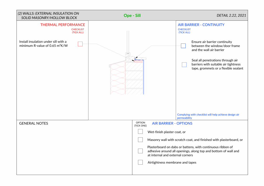
Ope - Sill
AIR BARRIER - OPTIONS
THERMAL PERFORMANCE
GENERAL NOTES
DETAIL 2.22, 2021
AIR BARRIER - CONTINUITY
CHECKLIST
(TICK ALL)
CHECKLIST
(TICK ALL)
OPTION
(TICK ONE)
Complying with checklist will help achieve design air
permeability
(2) WALLS: EXTERNAL INSULATION ON
SOLID MASONRY/HOLLOW BLOCK
Seal all penetrations through air
barriers with suitable air tightness
tape, grommets or a flexible sealant
Install insulation under sill with a
minimum R-value of 0.65 m²K/W
Wet-finish plaster coat, or
Masonry wall with scratch coat, and finished with plasterboard, or
Airtightness membrane and tapes
Plasterboard on dabs or battens, with continuous ribbon of
adhesive around all openings, along top and bottom of wall and
at internal and external corners
Ensure air barrier continuity
between the window/door frame
and the wall air barrier

Corner / Inverted Corner
AIR BARRIER - OPTIONS
THERMAL PERFORMANCE
Complying with checklist will help achieve design air
permeability
GENERAL NOTES
(TICK ALL)
CHECKLIST
(TICK ALL)
OPTION
(TICK ONE)
DETAIL 2.23, 2021
AIR BARRIER - CONTINUITY
CHECKLIST
2.23.1 2.23.2
(2) WALLS: EXTERNAL INSULATION ON
SOLID MASONRY/HOLLOW BLOCK
Seal all penetrations through air
barriers with suitable air tightness
tape, grommets or a flexible sealant
Wet-finish plaster coat, or
Masonry wall with scratch coat, and finished with plasterboard, or
Airtightness membrane and tapes
Plasterboard on dabs or battens, with continuous ribbon of
adhesive around all openings, along top and bottom of wall and
at internal and external corners
Ensure insulation continuity
throughout junction