2019 rogue hybrid...hybrid system is in the ready to drive mode.for additional information,refer to...
TRANSCRIPT

2019 ROGUE HYBRIDOWNER’S MANUAL
and MAINTENANCE INFORMATION
For your safety, read carefully and keep in this vehicle.
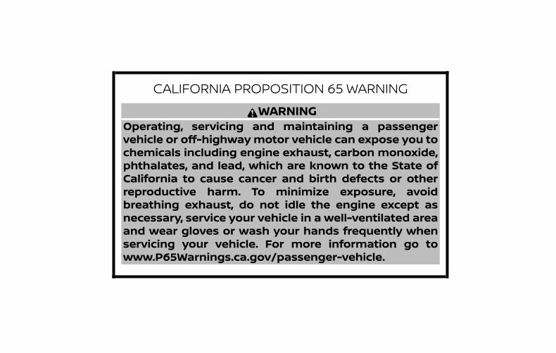
CALIFORNIA PROPOSITION 65 WARNINGWARNING
Operating, servicing and maintaining a passengervehicle or off-highwaymotor vehicle can expose you tochemicals including engine exhaust, carbon monoxide,phthalates, and lead, which are known to the State ofCalifornia to cause cancer and birth defects or otherreproductive harm. To minimize exposure, avoidbreathing exhaust, do not idle the engine except asnecessary, service your vehicle in a well-ventilated areaand wear gloves or wash your hands frequently whenservicing your vehicle. For more information go towww.P65Warnings.ca.gov/passenger-vehicle.

This manual was prepared to help you un-derstand the operation and maintenanceof your vehicle so that you may enjoy manymiles (kilometers) of driving pleasure.Please read through this manual beforeoperating your vehicle.
A separate Warranty Information Book-let explains details about the warrantiescovering your vehicle. The “Maintenanceand schedules” section of this manualexplains details about maintaining andservicing your vehicle. Additionally, aseparate Customer Care/Lemon LawBooklet (U.S. only) will explain how to re-solve any concerns you may have withyour vehicle, and clarify your rights un-der your state’s lemon law.
When you require any service or have anyquestions, a NISSAN dealer will be glad toassist you with the extensive resourcesavailable to them.
In addition to factory-installed options,your vehicle may also be equipped withadditional accessories installed prior to de-livery. It is recommended that you visit aNISSAN dealer for details concerning theparticular accessories with which your ve-hicle is equipped. It is important that youfamiliarize yourself with all disclosures,
warnings, cautions and instructions con-cerning proper use of such accessoriesprior to operating the vehicle and/or ac-cessory. It is recommended that you visit aNISSAN dealer for details concerning theparticular accessories with which your ve-hicle is equipped.
Before driving your vehicle, please read thisOwner’s Manual carefully. This will ensurefamiliarity with controls and maintenancerequirements, assisting you in the safe op-eration of your vehicle.
WARNINGIMPORTANT SAFETY INFORMATIONREMINDERS!
Follow these important driving rules tohelp ensure a safe and comfortable tripfor you and your passengers!
∙ NEVER drive under the influence of al-cohol or drugs.
∙ ALWAYS observe posted speed limitsand never drive too fast forconditions.
∙ ALWAYS give your full attention todriving and avoid using vehicle fea-tures or taking other actions thatcould distract you.
∙ ALWAYS use your seat belts and ap-propriate child restraint systems. Pre-teen children should be seated in therear seat.
FOREWORD READ FIRST—THEN DRIVE SAFELY

∙ ALWAYS provide information aboutthe proper use of vehicle safety fea-tures to all occupants of the vehicle.
∙ ALWAYS review this Owner’s Manualfor important safety information.
For descriptions specified for all-wheeldrive models, an AWD mark is placed at thebeginning of the applicablesections/items.
As with other vehicles with features foroff-road use, failure to operate all-wheeldrive models correctly may result in lossof control or an accident. For additionalinformation, refer to “Driving safety pre-cautions” in the “Starting and driving”section of this manual.
ON-PAVEMENT AND OFF-ROAD DRIVINGThis vehicle will handle and maneuverdifferently from an ordinary passen-ger car because it has a higher centerof gravity for off-road use. As withother vehicles with features of thistype, failure to operate this vehiclecorrectly may result in loss of controlor an accident.
For additional information, refer to“On-pavement and off-road drivingprecautions”, “Avoiding collision androllover” and “Driving safety precau-tions” in the “Starting and driving”section of this manual.
MODIFICATION OF YOUR VEHICLEThis vehicle should not be modified.Modification could affect itsperformance, safety, emissions or du-rability and may even violate govern-mental regulations. In addition, dam-age or performance problemsresulting from modifications may notbe covered under NISSAN warranties.
WARNINGInstalling an aftermarket On-Board Di-agnostic (OBD) plug-in device that usesthe port during normal driving, for ex-ample remote insurance companymonitoring, remote vehicle diagnostics,telematics or engine reprogramming,may cause interference or damage tovehicle systems. We do not recommendor endorse the use of any aftermarketOBD plug-in devices, unless specificallyapproved by NISSAN. The vehicle war-ranty may not cover damage caused byany aftermarket plug-in device.

This manual includes information for allfeatures and equipment available on thismodel. Features and equipment in your ve-hicle may vary depending on model, trimlevel, options selected, order, date of pro-duction, region or availability. Therefore,you may find information about features orequipment that are not included or in-stalled on your vehicle.
All information, specifications and illustra-tions in this manual are those in effect at thetime of printing. NISSAN reserves the right tochange specifications, performance, designor component suppliers without notice andwithout obligation. From time to time,NISSAN may update or revise this manual toprovide Owners with the most accurate in-formation currently available. Please care-fully read and retain with this manual all re-vision updates sent to you by NISSAN toensure you have access to accurate and up-to-date information regarding your vehicle.Current versions of vehicle Owner’s Manualsand any updates can also be found in theOwner section of the NISSAN website athttps://owners.nissanusa.com/nowners/navigation/manualsGuide. If you havequestions concerning any information inyour Owner’s Manual, contact NISSAN Con-sumer Affairs. For contact information, re-
fer to the NISSAN CUSTOMER CARE PRO-GRAM page in this Owner’s Manual.
IMPORTANT INFORMATION ABOUTTHIS MANUALYou will see various symbols in this manual.They are used in the following ways:
WARNINGThis is used to indicate the presence ofa hazard that could cause death or seri-ous personal injury. To avoid or reducethe risk, the procedures must be fol-lowed precisely.
CAUTIONThis is used to indicate the presence ofa hazard that could cause minor ormoderate personal injury or damage toyour vehicle. To avoid or reduce the risk,the procedures must be followedcarefully.
If you see this symbol, it means “Do not dothis” or “Do not let this happen.”
If you see a symbol similar to these in anillustration, it means the arrow points tothe front of the vehicle.
Arrows in an illustration that are similar tothese indicate movement or action.
APD1005
WHEN READING THE MANUAL
Arrows in an illustration that are similar tothese call attention to an item in the illus-tration.
CALIFORNIA PERCHLORATEADVISORYSome vehicle parts, such as lithium bat-teries, may contain perchlorate material.The following advisory is provided: “Per-chlorate Material – special handling mayapply. For additional information, referto www.dtsc.ca.gov/hazardouswaste/perchlorate/”.
© 2018 NISSAN NORTH AMERICA, INC.
All rights reserved. No part of this Owner’sManual may be reproduced or stored in aretrieval system, or transmitted in anyform, or by any means, electronic, me-chanical, photocopying, recording or oth-erwise, without the prior written permis-sion of Nissan North America, Inc.

NISSAN CARES . . .
Both NISSAN and your NISSAN dealer are dedicated to serving all your automotive needs. Your satisfaction with your vehicle and yourNISSAN dealer are our primary concerns. Your NISSAN dealer is always available to assist you with all your automobile sales and serviceneeds.However, if there is something that yourNISSAN dealer cannot assist you with oryou would like to provide NISSAN directlywith comments or questions, please con-tact the NISSAN Consumer Affairs Depart-ment using our toll-free number:
For U.S. customers1-800-NISSAN-1(1-800-647-7261)
For Canadian customers1-800-387-0122
The Consumer Affairs Department will askfor the following information:
– Your name, address, and telephonenumber
– Vehicle identification number (attachedto the top of the instrument panel on thedriver’s side)
– Date of purchase
– Current odometer reading
– Your NISSAN dealer’s name
– Your comments or questions
OR
You can write to NISSAN with the informa-tion at:
For U.S. customersNissan North America, Inc.Consumer Affairs DepartmentP.O. Box 685003Franklin, TN 37068-5003or via e-mail at:[email protected]
For Canadian customersNissan Canada Inc.5290 Orbitor DriveMississauga, Ontario L4W 4Z5or via e-mail at:[email protected]
If you prefer, visit us at:www.nissanusa.com (for U.S. customers)orwww.nissan.ca (for Canadian customers)
We appreciate your interest in NISSAN and thank you for buying a quality NISSAN vehicle.
NISSAN CUSTOMER CARE PROGRAM

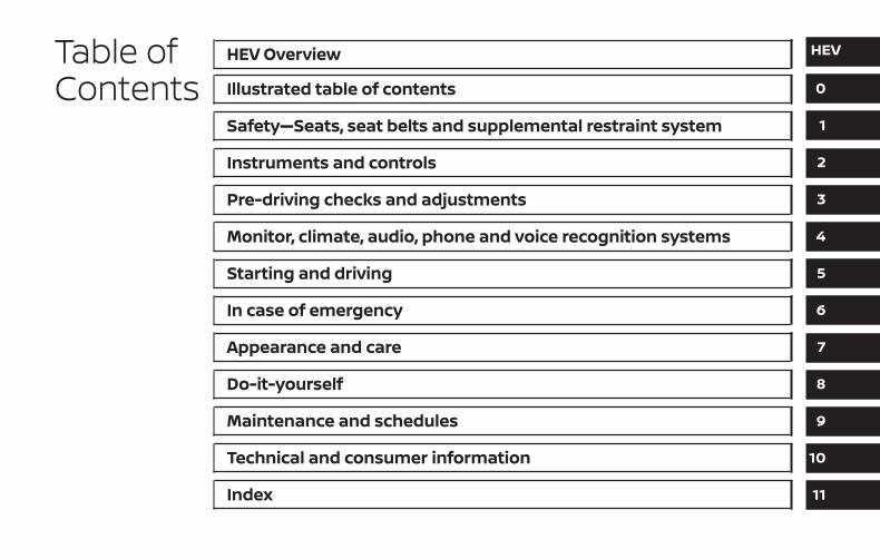
Table ofContents
HEV Overview
Illustrated table of contents
Safety—Seats, seat belts and supplemental restraint system
Instruments and controls
Pre-driving checks and adjustments
Monitor, climate, audio, phone and voice recognition systems
Starting and driving
In case of emergency
Appearance and care
Do-it-yourself
Maintenance and schedules
Technical and consumer information
Index
HEV
0
1
2
3
4
5
6
7
8
9
10
11


HEV Overview
NISSAN PURE DRIVE® Hybrid System . . . . . . . . . . HEV-2Lithium-ion (Li-ion) battery . . . . . . . . . . . . . . . . . . . HEV-2High-voltage cautions . . . . . . . . . . . . . . . . . . . . . . . . HEV-3Road accident cautions . . . . . . . . . . . . . . . . . . . . . . HEV-3Emergency shut-off system . . . . . . . . . . . . . . . . . . HEV-4Operation of the hybrid system. . . . . . . . . . . . . . . HEV-5
Starting and slow speed driving . . . . . . . . . . . HEV-5Medium or high speed driving . . . . . . . . . . . . . HEV-5Rapid acceleration. . . . . . . . . . . . . . . . . . . . . . . . . HEV-5Deceleration and braking. . . . . . . . . . . . . . . . . . HEV-6Stopping . . . . . . . . . . . . . . . . . . . . . . . . . . . . . . . . . . HEV-6
Energy monitors . . . . . . . . . . . . . . . . . . . . . . . . . . . . . HEV-6Assist charge gauge. . . . . . . . . . . . . . . . . . . . . . . HEV-6
Energy Flow (models with NavigationSystem) . . . . . . . . . . . . . . . . . . . . . . . . . . . . . . . . . . . HEV-7Fuel Economy . . . . . . . . . . . . . . . . . . . . . . . . . . . . . HEV-9Energy/Fuel History (models withNavigation System). . . . . . . . . . . . . . . . . . . . . . . . HEV-9
Regenerative brake. . . . . . . . . . . . . . . . . . . . . . . . . . HEV-10Efficient use of your vehicle . . . . . . . . . . . . . . . . . . .HEV-11Approaching Vehicle Sound for Pedestrians(VSP) system . . . . . . . . . . . . . . . . . . . . . . . . . . . . . . . . .HEV-11Hybrid vehicle precautions . . . . . . . . . . . . . . . . . . HEV-12
High-voltage components and theirlocations . . . . . . . . . . . . . . . . . . . . . . . . . . . . . . . . . HEV-12Hybrid vehicle characteristics. . . . . . . . . . . . . HEV-13

The NISSAN PURE DRIVE® Hybrid Systemcombines the power of a gasoline engineand an electric motor to help minimize fuelconsumption and emissions.
Depending on driving conditions, the ve-hicle runs on a combination of the gasolineengine and the electric motor, whichever isbest for those conditions.
Because the gasoline engine charges theLithium-ion (Li-ion) battery as needed, thebattery does not have to be charged froman outside source like an all-electric ve-hicle.
WARNINGIf you continue to drive the vehicle whilethe warning is displayed, the hybridsystem may become temporarily inop-erative and the system cannot providepower to the wheels. This can result inreduced or zero vehicle speed. The re-duced speed or zero speed may belower than other traffic, which could in-crease the chance of a collision. If thevehicle cannot maintain a safe drivingspeed, pull to the side of the road in asafe area. If this occurs, place the shiftlever in the P (Park) position and theignition in the READY to drive positionwith the vehicle stopped until the dis-play turns off. The “Hybrid System Over-heated Stop Vehicle” warning and the“Shift to Park” warning will be alter-nately displayed. For additional infor-mation, refer to “Vehicle informationdisplay warnings and indicators” in the“Instruments and controls” section ofthis manual.
WARNINGYour vehicle contains a sealed Lithium-ion (Li-ion) high-voltage battery. If theLi-ion battery is disposed of improperly,there is a risk of severe burns and elec-trical shock that may result in seriousinjury or death and there is also a risk ofenvironmental damage.
CAUTION∙ Do not misuse the Li-ion battery.
∙ Do not use the Li-ion battery for anyother purpose.
The Li-ion battery is used to drive the elec-tric motors in the NISSAN PURE DRIVE® Hy-brid System.
The Li-ion battery has a limited service life.It is recommended that you visit a NISSANdealer for information about recycling ordisposal of the battery.
NISSAN PURE DRIVE® HYBRIDSYSTEM
LITHIUM-ION (Li-ion) BATTERY
HEV-2 HEV Overview

WARNING∙ The NISSAN PURE DRIVE® Hybrid Sys-
tem uses high voltage up to approxi-mately 235 volts. The system can behot while and after starting. Be care-ful of both the high voltage and thehigh temperature. Obey the warninglabels attached to the vehicle.
∙ Never touch, disassemble, remove orreplace high-voltage parts, harnessesand their connectors. High-voltageharnesses are orange. Touching, dis-assembling, removing or replacingthose parts and harnesses can causesevere burns or electric shock thatmay result in serious injury or death.The vehicle high-voltage system hasno user serviceable parts. It is recom-mended that you visit a NISSAN dealerfor any necessary maintenance.
∙ Never try to remove the service pluglocated in the cargo area. The serviceplug is used only when the vehicle isserviced by trained technicians wear-ing personal protection equipmentand is part of the high-voltage sys-tem. Touching the service plug cancause severe burns or electric shockthat may result in serious injury ordeath.
WARNINGIn case of a collision:
∙ If your vehicle is drivable, pull your ve-hicle off the road, put the transmis-sion in the P (Park) position, apply theparking brake and turn the NISSANPURE DRIVE® Hybrid System off.
∙ Check to see if there are exposedhigh-voltage parts and cables. Nevertouch the parts and cables. For addi-tional information on their locations,refer to “High-voltage componentsand their locations” in this section. Toavoid personal injury, never touchhigh-voltage wiring, connectors, andother high-voltage parts, such as theelectric motor inverter and Li-ion bat-tery. An electric shock may occur ifexposed electric wires are visiblewhen viewed from inside or outside ofyour vehicle. Therefore, never touchexposed electric wires.
∙ If the vehicle receives a strong impactto the floor while driving, stop the ve-hicle in a safe location and check thefloor.
HIGH-VOLTAGE CAUTIONS ROAD ACCIDENT CAUTIONS
HEV Overview HEV-3
∙ Inspect the ground under the vehicle.If liquid has leaked onto the ground,the fuel system may have been dam-aged. Leave the vehicle as soon aspossible.
∙ Leaks or damage to the Li-ion batterymay result in a fire. If you discoverthem, contact emergency servicesimmediately. Since the fluid leak maybe lithium organic electrolyte fromthe Li-ion battery, never touch thefluid leak inside or outside the vehicle.If the fluid contacts your skin or eyes,wash it off immediately with a largeamount of water and receive immedi-ate medical attention to help avoidserious injury.
∙ If a fire occurs in the hybrid vehicle,leave the vehicle as soon as possible.Only use a type ABC, BC or C fire extin-guisher that is meant for use on elec-trical fires. Using water or the incor-rect fire extinguisher can result inserious injury or death from electricalshock.
∙ If you are not able to safely assess thevehicle due to vehicle damage, do nottouch the vehicle. Leave the vehicleand contact emergency services. Ad-vise first responders that this is a hy-brid vehicle.
∙ In the event of an accident that re-quires body repair and painting, thevehicle should be delivered to aNISSAN dealer to have the Li-ion bat-tery pack and high-voltage parts suchas the inverter, including the wiringharness, removed prior to painting. Li-ion battery packs exposed to heat inthe paint booth will experience capac-ity loss. Damaged Li-ion battery packsmay also pose safety risks to un-trained mechanics and repairpersonnel.
The emergency shut-off system is activatedand the high-voltage system automaticallyturns off in the following conditions:
∙ Front and side collisions in which the airbags are deployed.
∙ Certain rear collisions.
∙ Certain NISSAN PURE DRIVE® HybridSystem malfunctions.
For the above collisions and the certainhybrid system malfunctions, the READY todrive indicator light will turn off. For addi-tional information, refer to “Warning lights,indicator lights and audible reminders” inthe “Instruments and controls” section ofthis manual.
The emergency shut-off activates for theabove collisions to minimize risk of an eventthat could cause injury or an accident. If theemergency shut-off system activates, thehybrid system may not switch to the READYto drive position. It is recommended thatyou visit a NISSAN dealer. Even if the ignitionswitch is placed in the READY to drive posi-tion, the system may shut off suddenly.Therefore, drive cautiously to the nearestNISSAN dealer or contact a NISSAN dealer assoon as possible.
EMERGENCY SHUT-OFF SYSTEM
HEV-4 HEV Overview

To start the NISSAN PURE DRIVE® HybridSystem, depress the brake pedal and placethe ignition switch in the ON position whenthe transmission is in the P (Park) position.
CAUTIONDo not start the system in the N (Neu-tral) position under cold condition ofthe system. Start in the P (Park) positionin that case.
The READY to drive indicator lightflashes until the hybrid system is ready todrive.If starting in a low temperature environ-ment, the flashing time of the READY todrive indicator light becomes longer.It cannot move out from the P (Park) rangeduring flashing.When the READY to drive indicatorlight illuminates, the vehicle can bedriven, even if the gasoline engine is notrunning.
NOTE:
The gasoline engine starts and stops au-tomatically. It may stop during decelera-tion or when the vehicle is stopped.The gasoline engine may automaticallyrun in the following conditions:
∙ The level of remaining charge in the Li-ion battery is low. The engine runs tocharge the Li-ion battery and to providepower to drive the vehicle.
∙ The temperature of the engine coolantis low.
∙ When the A/C is used.
∙ When opening the door.
∙ When the engine hood is opened.
∙ When applying the brakes.
∙ Based on driving conditions.
∙ The shift lever is moved to the P (Park)position, the driver’s seat belt is re-leased and the driver’s side door is thenopened.
The hybrid system operates as followsbased on driving conditions and the Li-ionbattery charge.
The engine is hard to stop during thesedriving conditions:
∙ When the A/C is on and outside tem-perature is high/low.
∙ When repeatedly starting and stoppingthe engine.
STARTING AND SLOW SPEEDDRIVINGIn some cases, the vehicle can be driven bythe electric motor during extremely slowspeed creep, but the engine starts whenaccelerating or releasing the brakes.
MEDIUM OR HIGH SPEED DRIVINGThe system automatically controls thegasoline engine and electric motor in orderto obtain the optimum fuel mileage andperformance, depending on the drivingsituation and available Li-ion batterycharge.
When the remaining battery level is low, theLi-ion battery is charged by the electricmotor that is driven to generate electricpower while the vehicle is driving.
RAPID ACCELERATIONThe vehicle is accelerated using both thegasoline engine and the electric motor de-pending on the available Li-ion batterycharge.
OPERATION OF THE HYBRID SYSTEM
HEV Overview HEV-5

DECELERATION AND BRAKINGThe Li-ion battery is charged by the electricmotor that changes the energy of the ro-tating wheels into electric power. For addi-tional information, refer to “Regenerativebrake” in this section.
STOPPINGThe gasoline engine may stop running tosave fuel depending on the available Li-ionbattery charge.
The NISSAN PURE DRIVE® Hybrid Systemdisplays the energy flow between the en-gine, Li-ion battery, and tires on the ad-vanced drive assist display in the meter.The status is shown on the assist chargegauge in the meter and the energyflow/remaining Li-ion battery charge in thevehicle information display. System statuscan also be shown on the navigation sys-tem display (if so equipped) and the meterwhen the screen is in the Energy Flowmode or energy/fuel history mode.
ASSIST CHARGE GAUGEThis meter displays the actual electric mo-tor power consumption and the chargingpower to the Li-ion battery.
For additional information, refer to “Assistcharge gauge” in the “Instruments andcontrols” section of this manual.
LHV2050
ENERGY MONITORS
HEV-6 HEV Overview

ENERGY FLOW (models withNavigation System)When you use this system, make sure thehybrid system is in the READY to drivemode. For additional information, refer to“Operation of the hybrid system” in thissection.
If you use the system with the hybridsystem off for a long time, it will dis-charge the 12-volt battery power, andthe hybrid system will not start.
The energy monitor for various operatingmodes can be displayed on the navigationsystem monitor and the meter.
1. Press the MENU button on the controlpanel.
2. Select the “Info” key by touching thetouch-screen.
3. Select the “Vehicle” key by touching thetouch-screen or highlight the “Vehicle”key on the display by using theTUNE/SCROLL knob and press the OKbutton.
4. Select the “Energy Flow” key by touch-ing the touch-screen or highlight the“Energy Flow” key on the display by us-ing the TUNE/SCROLL knob and pressthe OK button.
This is an example of the Energy Flowscreen. The Energy Flow display changes,depending on the following operating con-ditions. The graphic indicates the amountof power in the Li-ion battery.
LHV2117
HEV Overview HEV-7

The following are displayed on the EnergyFlow screen:
∙ When the vehicle is powered only by theelectric motor �A or gasoline engine �E
∙ When the vehicle is powered by boththe electric motor and the gasoline en-gine �B
∙ When the vehicle is charging the Li-ionbattery with the regenerative brake �Dor gasoline engine �H
∙ When the vehicle is charging the Li-ionbattery with the regenerative brake andgasoline engine �C
∙ When the vehicle is powered by thegasoline engine and is charging the Li-ion battery �G
∙ When there is no Energy Flow in thevehicle �F
*Remaining capacity of Li-ion battery
The Energy Flow and remaining Li-ion bat-tery charge can also be shown on the ve-hicle information display. For additional in-formation, refer to “Vehicle informationdisplay” in the “Instruments and controls”section of this manual.
LHV2062
HEV-8 HEV Overview

FUEL ECONOMY
Press the buttons on the steer-ing wheel to go backward or forwardthrough the vehicle information menuitems until “Fuel Economy” appears on thevehicle information display screen.This screen displays the rate of fuel con-sumption and distance to empty.
ENERGY/FUEL HISTORY (modelswith Navigation System)The Energy/Fuel History screen appears inthe display with the navigation systemwhen the screen is in the Energy/Fuel His-tory mode.
1. Press the MENU button on the controlpanel.
2. Select the “Info” key by touching thetouch-screen.
3. Select the “Vehicle” key by touching thetouch-screen or highlight the “Vehicle”key on the display by using theTUNE/SCROLL knob and press the OKbutton.
4. Select the “Energy Flow” key by touch-ing the touch-screen or highlight the“Energy Flow” key on the display by us-ing the TUNE/SCROLL knob and pressthe OK button.
5. Select the “History” key by touching thetouch-screen or highlight the “History”key on the display by using theTUNE/SCROLL knob and press the OKbutton.
The Energy/Fuel History screen can be dis-played on the navigation system monitor.This displays the vehicle’s average fuelconsumption and regenerative electricpower at 2 minute intervals.
LSD3337 LHV2118
HEV Overview HEV-9

The displayed values on the screen indi-cate general driving conditions. Accuracyvaries with driving habits and road condi-tions.
∙ Regenerated energy in the past 12 min-utes: The regenerated energy in thepast 12 minutes is indicated with sym-bols. One symbol indicates a 30 watt-hour. The energy of a 30 watt-hour illu-minates a 30 watt bulb for an hour.
∙ Fuel consumption in the past 12 min-utes: Fuel consumption in the past12 minutes is displayed.
∙ Current fuel consumption (Last col-umn): The current fuel consumption iscalculated and displayed based on dis-tance and fuel consumption.
NOTE:
Information shown in the yellow columnmeans current (within 2 minutes) and in-formation shown in the blue columnsmeans past (more than 2 minutes).
This vehicle is equipped with two brakingsystems:
∙ Hydraulic brake system
∙ Regenerative brake system
When the vehicle decelerates while the ve-hicle is driven with the shift lever in the D(Drive) position, the Li-ion battery can becharged by the electric motor. The electricmotor converts the energy of the rotatingwheels into electric power under the fol-lowing circumstances:
∙ When the accelerator pedal is released
∙ When the brake pedal is depressed
∙ When there is no malfunction in thebrake system or the NISSAN PUREDRIVE® Hybrid System
The regenerative brake may not workproperly if the vehicle is installed with tiresand road wheels other than the onesspecified in this manual.
While the regenerative cooperative brakesystem is operating, you might feel a slightvibration or hear the system working whenbraking. This is normal.
The regenerative cooperative brake sys-tem controls both hydraulic and regenera-tive brakes. If you feel unusual decelerationwhen braking, have the brake and hybridsystems checked. It is recommended thatyou visit a NISSAN dealer for this service.
REGENERATIVE BRAKE
HEV-10 HEV Overview

Drive your vehicle with smooth accelera-tion and deceleration.
∙ While driving, energy is recoveredthrough the regenerative brake as thevehicle decelerates. However, for mostefficient use, do not accelerate or decel-erate your vehicle more than neces-sary.
∙ Avoid abrupt acceleration and decel-eration.
∙ The power of the Li-ion battery can bechecked on the Energy Flow in the cen-ter display (models with Navigation Sys-tem) or Li-ion battery status meter inthe vehicle information display. For ad-ditional information, refer to “EnergyFlow (models with Navigation System)”in this section or “Vehicle informationdisplay” in the “Instruments and con-trols” section of this manual. Gradual ornon-abrupt acceleration and decelera-tion will make more effective use of theelectric power.
∙ When parking, be sure to place the shiftlever in the P (Park) position. While driv-ing, place the shift lever in the D (Drive)position.
The VSP system is a function that usessound to help alert pedestrians of thepresence of the vehicle when it is beingdriven at a low speed in the electric drivemode under the following conditions:
∙ The sound starts when the vehiclestarts accelerating.
∙ The sound stops when the vehiclespeed is more than 19 mph (30 km/h)while accelerating only when the ve-hicle is powered by the electric motor.
∙ The sound starts when the vehiclespeed is less than 16 mph (25 km/h)while decelerating only when the ve-hicle is powered by the electric motor.
∙ The sound stops when the vehiclestops.
∙ The sound does not stop with the ve-hicle in the R (Reverse) position even ifthe vehicle stops.
The VSP system is automatically turned onwhen the vehicle is in the READY to drivemode.
If there is a malfunction in the VSP system,the VSP OFF indicator light in the meterilluminates. For additional information, re-fer to “Approaching Vehicle Sound for Pe-destrians (VSP) OFF indicator light” in the“Instruments and controls” section of thismanual.
WARNING∙ If the sound from the VSP system is
not heard while driving, stop the ve-hicle in a safe and quiet location. Opena window, and then place the vehiclein the R (Reverse) position with thebrake pedal firmly depressed. Checkthat the operating sound can beheard from the front side of thevehicle.
∙ If the sound cannot be heard, it is rec-ommended that you immediatelycontact a NISSAN dealer forinspection.
EFFICIENT USE OF YOUR VEHICLE APPROACHING VEHICLE SOUND FORPEDESTRIANS (VSP) SYSTEM
HEV Overview HEV-11

HIGH-VOLTAGE COMPONENTSAND THEIR LOCATIONS
WARNING∙ The NISSAN PURE DRIVE® Hybrid Sys-
tem uses high voltage up to approxi-mately 235 volts. The system can behot during and after starting. Be care-ful of both the high voltage and thehigh temperature. Obey the warninglabels attached to the vehicle.
∙ Never touch, disassemble, remove orreplace the high-voltage parts, har-nesses and their connectors. High-voltage harnesses are orange. Touch-ing, disassembling, removing orreplacing those parts and harnessescan cause severe burns or electricshock that may result in serious injuryor death.
LSD3338
HYBRID VEHICLE PRECAUTIONS
HEV-12 HEV Overview

1. Lithium-ion (Li-ion) battery2. Service plug3. DC/DC converter4. 12-volt battery5. High-voltage harness6. Traction motor inverter7. Traction motorThe hybrid system uses high voltage up toapproximately 235 volts. High-voltagecomponents are indicated in the illustra-tion. High-voltage harnesses are orange.The system can be hot during and afterstarting. Be careful of both the high voltageand the high temperature.
HYBRID VEHICLECHARACTERISTICS
WARNING∙ When you leave your vehicle, be sure
to place the ignition switch in the OFFposition.
∙ Be sure to put the transmission in theP (Park) position because the vehiclecan move when the READY to driveindicator light is on even if the gaso-line engine is not running. When theREADY to drive indicator light is on, donot leave your vehicle in a shift posi-tion other than the P (Park) position.The vehicle will creep and startabruptly if the accelerator pedal is de-pressed by mistake. This may causeserious injury or death.
CAUTIONIf the vehicle is parked for a long periodof time, the battery discharges gradu-ally. To avoid this occurrence, drive thevehicle for approximately 30 minutes atleast once every two to three months.Otherwise, the Li-ion battery may bedamaged. If the Li-ion battery is com-pletely discharged and the hybrid sys-tem cannot be activated, it is recom-mended that you visit a NISSAN dealer.
High-voltage parts and harnesses on thehybrid vehicles emit approximately thesame amount of electromagnetic wavesas the conventional gasoline-powered ve-hicles or home electronic appliances de-spite their electromagnetic shieldings.
Charging the Li-ion battery while driving isimportant. The vehicle cannot run if the Li-ion battery is discharged. When in the N(Neutral) position and while both the accel-erator pedal and the brake pedal are notdepressed, the Li-ion battery does not re-charge. Leaving the transmission in the N(Neutral) position, while both the acceleratorpedal and the brake pedal are not de-pressed for an extended period of time, maydischarge the Li-ion battery and the hybridsystem may automatically be turned off.
HEV Overview HEV-13
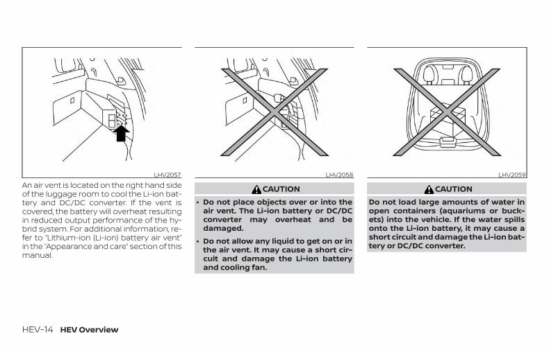
An air vent is located on the right hand sideof the luggage room to cool the Li-ion bat-tery and DC/DC converter. If the vent iscovered, the battery will overheat resultingin reduced output performance of the hy-brid system. For additional information, re-fer to “Lithium-ion (Li-ion) battery air vent”in the “Appearance and care” section of thismanual.
CAUTION∙ Do not place objects over or into the
air vent. The Li-ion battery or DC/DCconverter may overheat and bedamaged.
∙ Do not allow any liquid to get on or inthe air vent. It may cause a short cir-cuit and damage the Li-ion batteryand cooling fan.
CAUTIONDo not load large amounts of water inopen containers (aquariums or buck-ets) into the vehicle. If the water spillsonto the Li-ion battery, it may cause ashort circuit and damage the Li-ion bat-tery or DC/DC converter.
LHV2057 LHV2058 LHV2059
HEV-14 HEV Overview

Noise and vibrationAfter the hybrid system is activated, thefollowing noises and vibrations that areunique to the hybrid system may occur.The following situations do not indicate amalfunction:
∙ Electric motor noise from the enginecompartment
∙ Noise from the rear of the vehicle whenthe hybrid system activates or deacti-vates
∙ Noise and vibration when the gasolineengine starts running or stops
∙ Operating noise or electric motor noisewhen releasing the accelerator pedal ordepressing the brake pedal
∙ Engine noise due to rapid acceleration
∙ Fan noise from the air inlet located onthe rear parcel shelf
∙ Noise from the climate control system
HEV Overview HEV-15

MEMO
HEV-16 HEV Overview

0 Illustrated table of contents
Air bags, seat belts and child restraints . . . . . . . . . . 0-2Exterior front . . . . . . . . . . . . . . . . . . . . . . . . . . . . . . . . . . . . 0-3Exterior rear . . . . . . . . . . . . . . . . . . . . . . . . . . . . . . . . . . . . . 0-4Passenger compartment. . . . . . . . . . . . . . . . . . . . . . . . 0-5
Instrument panel . . . . . . . . . . . . . . . . . . . . . . . . . . . . . . . . 0-6Engine compartment check locations . . . . . . . . . . . 0-8Warning and indicator lights . . . . . . . . . . . . . . . . . . . . . 0-9

1. Supplemental air bags (P. 1-45)2. Occupant classification sensor
(weight sensor) (P. 1-45)3. Front Seat belt with pretensioner(s)
and shoulder heights adjuster(P. 1-11, 1-45)
4. Head restraints/headrests (P. 1-7)5. Roof-mounted curtain side-impact
and rollover supplemental air bag(P. 1-45)
6. 2nd row center position top tetherstrap (located on ceiling) (P. 1-23)
7. 2nd row outboard seat top tetherstrap anchor (located on bottomof seatback) (P. 1-23)
8. LATCH (Lower Anchors and Tethersfor CHildren) (P. 1-23)
9. Folding 2nd row bench (P. 1-2)10. Front seat-mounted side-impact
supplemental air bag (P. 1-45)11. Seats (P. 1-2)Refer to the page number indicated inparentheses for operating details.
LII2549
AIR BAGS, SEAT BELTS AND CHILDRESTRAINTS
0-2 Illustrated table of contents

1. Engine hood (P. 3-23)2. Wiper and washer switch (P. 2-43)
Wiper blades (P. 8-16)3. Windshield (P. 8-16)
Windshield-washer fluid (P. 8-12)4. Power windows (P. 2-67)5. Door locks (P. 3-4)
NISSAN Intelligent Key® (P. 3-7)Keys (P. 3-2)
6. Mirrors (P. 3-36)Side view camera (if so equipped)(P. 4-11)
7. Tire pressure (P. 8-28)Flat tire (P. 6-3)Tire chains (P. 8-28)
8. Fog light switch (if so equipped)(P. 2-46)LED Daytime Running Lights (DRL)system (P. 2-46)
9. Headlight and turn signal switch(P. 2-46)Replacing bulbs (P. 8-23)
10. Front view camera (if so equipped)(P. 4-11)
Refer to the page number indicated inparentheses for operating details.
LII2540
EXTERIOR FRONT
Illustrated table of contents 0-3

1. Wiper and washer switch (P. 2-43)2. Child safety rear door lock (P. 3-4)3. Fuel-filler door (P. 3-31)
Fuel-filler cap (P. 3-31)Fuel recommendation (P. 10-2)
4. Replacing bulbs (P. 8-23)5. Rearview camera (P. 4-3, 4-11)6. Liftgate release (P. 3-24)7. Rear sonar sensors (if so equipped)
(P. 5-119)Refer to the page number indicated inparentheses for operating details.
LII2554
EXTERIOR REAR
0-4 Illustrated table of contents

1. Glove box (P. 2-60)2. Map lights (P. 2-72)3. Power panoramic moonroof
(if so equipped) (P. 2-70)4. Console box (P. 2-60)5. Luggage hooks (P. 2-60)6. Center armrest (2nd row)
(P. 2-60)7. Cup holders (P. 2-60)8. Sun visors (P. 3-34)
Refer to the page number indicated inparentheses for operating details.
LIC3720
PASSENGER COMPARTMENT
Illustrated table of contents 0-5

1. Vent (P. 4-29)2. Headlight/fog light (if so
equipped)/turn signal switch(P. 2-46)
3. Meters and gauges (P. 2-4)Warning and indicator lights(P. 2-10)Vehicle information display (P. 2-21)
4. Wiper and washer switch (P. 2-43)Rear wiper washer switch (P. 2-43)
5. Push-button ignition switch(P. 5-14)
6. Hazard warning flasher switch(P. 6-2)
7. Radio*Navigation system*(if so equipped)
8. Front passenger supplemental airbag (P. 1-45)
9. Glove box (P. 2-60)10. Heater and air conditioning
controls (P. 4-30)11. Power outlet (P. 2-57)12. Shift lever (P. 5-19)13. Auxiliary jack*
USB port*14. Front passenger air bag status
light (P. 1-45)LII2516
INSTRUMENT PANEL
0-6 Illustrated table of contents

15. Cruise control switches(if so equipped) (P. 5-55)Intelligent Cruise Control (ICC)switches (if so equipped) (P. 5-57)Bluetooth® Hands-Free PhoneSystem*
16. Driver supplemental air bag(P. 1-45)Horn (P. 2-52)
17. Tilt and telescopic steering (P. 3-34)18. Control panel and vehicle informa-
tion display switches (P. 2-21)19. Hood release (P. 3-23)20. SPORT mode switch (P. 5-25)
Fuel door release (P. 3-31)ECO mode switch (P. 5-25)Liftgate instrument panel switch(if so equipped) (P. 3-24)All-Wheel Drive (AWD) LOCK switch(if so equipped) (P. 2-56)Vehicle Dynamic Control (VDC) OFFswitch (P. 2-55)Heated steering wheel switch(if so equipped) (P. 2-54)Dynamic driver assistance switch(if so equipped) (P. 2-54)
21. Instrument brightness control(P. 2-51)Twin trip odometer reset switch(P. 2-5)
*: Refer to the separate NissanConnect®Owner’s Manual.
Refer to the page number indicated inparentheses for operating details.
Illustrated table of contents 0-7

MR20DD engine1. Engine coolant reservoir (P. 8-4)2. Windshield-washer fluid reservoir
(P. 8-12)3. Inverter coolant reservoir (P. 8-6)4. Engine oil dipstick (P. 8-7)5. Engine oil filler cap (P. 8-7)6. Brake fluid reservoir (P. 8-11)7. Air cleaner (P. 8-15)8. Fuse box (P. 8-20)9. Radiator cap (P. 8-4)Engine cover removed for clarity.
The 12–volt battery is located in the rearcargo area of the vehicle.
Refer to the page number indicated inparentheses for operating details.
LDI3135
ENGINE COMPARTMENT CHECKLOCATIONS
0-8 Illustrated table of contents

Warninglight
Name Page
12–volt batterycharge warninglight
2-11
or
Anti-lock BrakingSystem (ABS)warning light
2-11
Automatic Emer-gency Braking(AEB) systemwarning light (if soequipped)
2-11
Automatic Emer-gency Braking(AEB) with Pedes-trian Detectionsystem warninglight (if soequipped)
2-12
Warninglight
Name Page
or
Brake warninglight (red)
2-12
Electronicallycontrolled brakewarning light (yel-low)
2-12
Low tire pressurewarning light
2-13
Master warninglight
2-15
Power steeringwarning light
2-15
PURE DRIVE® Hy-brid systemwarning light
2-16
Warninglight
Name Page
Rear AutomaticBraking (RAB)warning light (if soequipped)
2-16
Seat belt warninglight and chime
2-16
Supplemental airbag warning light
2-16
Indicatorlight
Name Page
All-Wheel Drive(AWD) LOCK indi-cator light (if soequipped)
2-17
Approaching Ve-hicle Sound forPedestrians (VSP)OFF indicatorlight
2-17
WARNING AND INDICATOR LIGHTS
Illustrated table of contents 0-9
Indicatorlight
Name Page
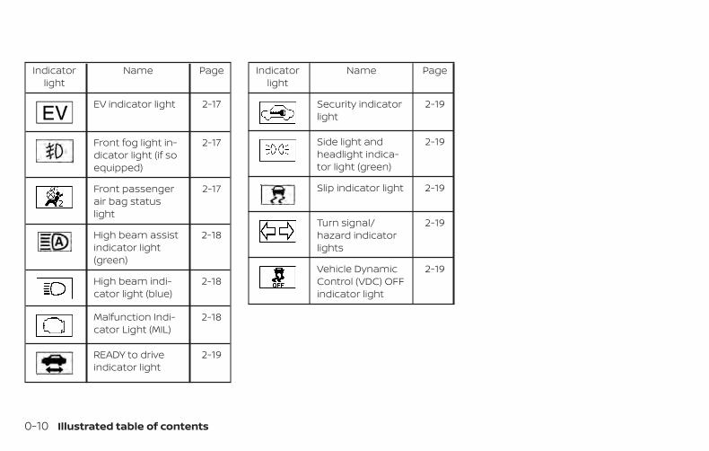
EV indicator light 2-17
Front fog light in-dicator light (if soequipped)
2-17
Front passengerair bag statuslight
2-17
High beam assistindicator light(green)
2-18
High beam indi-cator light (blue)
2-18
Malfunction Indi-cator Light (MIL)
2-18
READY to driveindicator light
2-19
Indicatorlight
Name Page
Security indicatorlight
2-19
Side light andheadlight indica-tor light (green)
2-19
Slip indicator light 2-19
Turn signal/hazard indicatorlights
2-19
Vehicle DynamicControl (VDC) OFFindicator light
2-19
0-10 Illustrated table of contents
1 Safety—Seats, seat belts andsupplemental restraint system
Seats . . . . . . . . . . . . . . . . . . . . . . . . . . . . . . . . . . . . . . . . . . . . 1-2Front manual seat adjustment(for passenger’s seat). . . . . . . . . . . . . . . . . . . . . . . . . .1-3Front power seat adjustment(for driver’s seat) . . . . . . . . . . . . . . . . . . . . . . . . . . . . . . 1-4Armrests . . . . . . . . . . . . . . . . . . . . . . . . . . . . . . . . . . . . . 1-5Flexible seating . . . . . . . . . . . . . . . . . . . . . . . . . . . . . . . 1-6
Head restraints/headrests . . . . . . . . . . . . . . . . . . . . . . .1-7Adjustable head restraint/headrestcomponents . . . . . . . . . . . . . . . . . . . . . . . . . . . . . . . . . 1-8Non-adjustable head restraint/headrest components. . . . . . . . . . . . . . . . . . . . . . . . 1-8Remove . . . . . . . . . . . . . . . . . . . . . . . . . . . . . . . . . . . . . . 1-9Install. . . . . . . . . . . . . . . . . . . . . . . . . . . . . . . . . . . . . . . . . 1-9Adjust . . . . . . . . . . . . . . . . . . . . . . . . . . . . . . . . . . . . . . . .1-10
Seat belts . . . . . . . . . . . . . . . . . . . . . . . . . . . . . . . . . . . . . . . 1-11Precautions on seat belt usage. . . . . . . . . . . . . . . 1-11Seat belt warning light. . . . . . . . . . . . . . . . . . . . . . . .1-14Pregnant women. . . . . . . . . . . . . . . . . . . . . . . . . . . . .1-14Injured persons. . . . . . . . . . . . . . . . . . . . . . . . . . . . . . .1-14Three-point type seat belt withretractor . . . . . . . . . . . . . . . . . . . . . . . . . . . . . . . . . . . . .1-14Seat belt extenders. . . . . . . . . . . . . . . . . . . . . . . . . . .1-19
Seat belt maintenance . . . . . . . . . . . . . . . . . . . . . . 1-20Child safety. . . . . . . . . . . . . . . . . . . . . . . . . . . . . . . . . . . . . 1-20
Infants . . . . . . . . . . . . . . . . . . . . . . . . . . . . . . . . . . . . . . .1-21Small children . . . . . . . . . . . . . . . . . . . . . . . . . . . . . . . .1-21Larger children . . . . . . . . . . . . . . . . . . . . . . . . . . . . . . .1-21
Child restraints . . . . . . . . . . . . . . . . . . . . . . . . . . . . . . . . . 1-23Precautions on child restraints . . . . . . . . . . . . . . 1-23LATCH (Lower Anchors and Tethers forCHildren) system . . . . . . . . . . . . . . . . . . . . . . . . . . . . 1-25Rear-facing child restraint installationusing LATCH. . . . . . . . . . . . . . . . . . . . . . . . . . . . . . . . . 1-28Rear-facing child restraint installationusing the seat belts . . . . . . . . . . . . . . . . . . . . . . . . . 1-30Forward-facing child restraintinstallation using LATCH . . . . . . . . . . . . . . . . . . . . . 1-33Forward-facing child restraintinstallation using the seat belts. . . . . . . . . . . . . . 1-36Booster seats . . . . . . . . . . . . . . . . . . . . . . . . . . . . . . . .1-41
Supplemental Restraint System (SRS). . . . . . . . . . . 1-45Precautions on SRS. . . . . . . . . . . . . . . . . . . . . . . . . . 1-45Supplemental air bag warning labels . . . . . . . . 1-63Supplemental air bag warning light. . . . . . . . . . 1-64

WARNING∙ Do not ride in a moving vehicle when
the seatback is reclined. This can bedangerous. The shoulder belt will notbe against your body. In an accident,you could be thrown into it and re-ceive neck or other serious injuries.You could also slide under the lap beltand receive serious internal injuries.
∙ For the most effective protectionwhen the vehicle is in motion, the seatshould be upright. Always sit wellback and upright in the seat with bothfeet on the floor and adjust the seatproperly. For additional information,refer to “Precautions on seat belt us-age” in this section.
∙ After adjustment, gently rock in theseat to make sure it is securely locked.
∙ Do not leave children unattended in-side the vehicle. They could unknow-ingly activate switches or controls ormake the vehicle move. Unattendedchildren could become involved in se-rious accidents.
∙ To help avoid risk of injury or deaththrough unintended operation of thevehicle and/or its systems, do notleave children, people who require theassistance of others or pets unat-tended in your vehicle. Additionally,the temperature inside a closed ve-hicle on a warm day can quickly be-come high enough to cause a signifi-cant risk of injury or death to peopleand pets.
∙ Do not adjust the driver’s seat whiledriving so full attention may be givento vehicle operation. The seat maymove suddenly and could cause lossof control of the vehicle.
∙ The seatback should not be reclinedany more than needed for comfort.Seat belts are most effective when thepassenger sits well back and straightup in the seat. If the seatback is re-clined, the risk of sliding under the lapbelt and being injured is increased.
ARS1152
SEATS
1-2 Safety—Seats, seat belts and supplemental restraint system
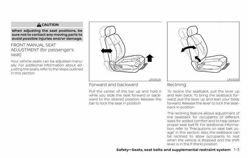
CAUTIONWhen adjusting the seat positions, besure not to contact any moving parts toavoid possible injuries and/or damage.
FRONT MANUAL SEATADJUSTMENT (for passenger’sseat)Your vehicle seats can be adjusted manu-ally. For additional information about ad-justing the seats, refer to the steps outlinedin this section.
Forward and backwardPull the center of the bar up and hold itwhile you slide the seat forward or back-ward to the desired position. Release thebar to lock the seat in position.
RecliningTo recline the seatback, pull the lever upand lean back. To bring the seatback for-ward, pull the lever up and lean your bodyforward. Release the lever to lock the seat-back in position.
The reclining feature allows adjustment ofthe seatback for occupants of differentsizes for added comfort and to help obtainproper seat belt fit. For additional informa-tion, refer to “Precautions on seat belt us-age” in this section. Also, the seatback canbe reclined to allow occupants to restwhen the vehicle is stopped and the shiftlever is in the P (Park) position.
LRS3029 LRS3030
Safety—Seats, seat belts and supplemental restraint system 1-3

FRONT POWER SEAT ADJUSTMENT(for driver’s seat)Operating tips
∙ The power seat motor has an auto-reset overload protection circuit. If themotor stops during operation, wait30 seconds, then reactivate the switch.
∙ Do not operate the power seat switchfor a long period of time when the Hy-brid System is not in the READY mode.This will discharge the vehicle battery.
For additional information, refer to “Auto-matic drive positioner” in “Pre-drivingchecks and adjustments” section of thismanual.
Forward and backwardMoving the switch as shown will slide theseat forward or backward to the desiredposition.
RecliningMove the recline switch as shown until thedesired angle is obtained.
The reclining feature allows adjustment ofthe seatback for occupants of differentsizes for added comfort and to help obtainproper seat belt fit. For additional informa-tion, refer to “Precautions on seat belt us-age” in this section. Also, the seatback canbe reclined to allow occupants to restwhen the vehicle is stopped and the shiftlever is in P (Park).
LRS2662
1-4 Safety—Seats, seat belts and supplemental restraint system

Seat lifterMove the switch as shown to achieve de-sired seat height.
Lumbar supportThe lumbar support feature provides ad-justable lower back support to the driver.Move the switch as shown to adjust theseatback lumbar area.
ARMRESTSThe rear bench center armrest is locked inthe up position. To lower the armrest, pullthe armrest down as shown.
To return the armrest to the up position,push up on the armrest until it is in the fullup position.
LRS2784 LRS2270 LRS3031
Safety—Seats, seat belts and supplemental restraint system 1-5

FLEXIBLE SEATING
WARNING∙ Never allow anyone to ride in the
cargo area or on the rear seats whenthey are in the fold-down position. In acollision, people riding in these areaswithout proper restraints are morelikely to be seriously injured or killed.
∙ Do not allow people to ride in any areaof your vehicle that is not equippedwith seats and seat belts. Be sure ev-eryone in your vehicle is in a seat andusing a seat belt properly.
∙ Do not allow more than one person touse the same seat belt.
∙ Do not fold down the rear seats whenoccupants are in the rear seat area orany luggage is on the rear seats.
– Make sure that the seat path isclear before moving the seat.
– Be careful not to allow hands orfeet to get caught or pinched in theseat.
∙ Head restraints/headrests should beadjusted properly as they may pro-vide significant protection against in-jury in an accident. Always replaceand adjust them properly if they havebeen removed for any reason.
∙ If the head restraints/headrests areremoved for any reason, they shouldbe securely stored to prevent themfrom causing injury to passengers ordamage to the vehicle in case of sud-den braking or an accident.
∙ When returning the seatbacks to theupright position, be certain they arecompletely secured in the latched po-sition. If they are not completely se-cured, passengers may be injured inan accident or sudden stop.
∙ Properly secure all cargo to help pre-vent it from sliding or shifting. Do notplace cargo higher than the seat-backs. In a sudden stop or collision,unsecured cargo could cause per-sonal injury.
Folding the rear bench seatTo fold the rear bench seat flat for maxi-mum cargo hauling:
1. Make sure that the head restraints arelowered or removed. To remove thehead restraints/headrests, push andhold the lock knob while moving thehead restraints in an upward direction.Store the head restraints properly sothey are not loose in the vehicle.
LRS2820
1-6 Safety—Seats, seat belts and supplemental restraint system
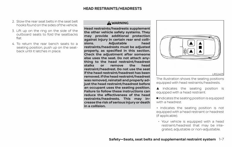
2. Stow the rear seat belts in the seat belthooks found on the sides of the vehicle.
3. Lift up on the ring on the side of theoutboard seats to fold the seatbacksflat.
4. To return the rear bench seats to aseating position, push up on the seat-back until it latches in place.
WARNINGHead restraints/headrests supplementthe other vehicle safety systems. Theymay provide additional protectionagainst injury in certain rear end colli-sions. Adjustable headrestraints/headrests must be adjustedproperly, as specified in this section.Check the adjustment after someoneelse uses the seat. Do not attach any-thing to the head restraint/headreststalks or remove the headrestraint/headrest. Do not use the seatif the head restraint/headrest has beenremoved. If the head restraint/headrestwas removed, reinstall and properly ad-just the head restraint/headrest beforean occupant uses the seating position.Failure to follow these instructions canreduce the effectiveness of the headrestraints/headrests. This may in-crease the risk of serious injury or deathin a collision.
The illustration shows the seating positionsequipped with head restraints/headrests.
� Indicates the seating position isequipped with a head restraint.
� Indicates the seating position is equippedwith a headrest.
+ Indicates the seating position is notequipped with a head restraint or headrest(if applicable).
∙ Your vehicle is equipped with a headrestraint/headrest that may be inte-grated, adjustable or non-adjustable.
LRS2403
HEAD RESTRAINTS/HEADRESTS
Safety—Seats, seat belts and supplemental restraint system 1-7
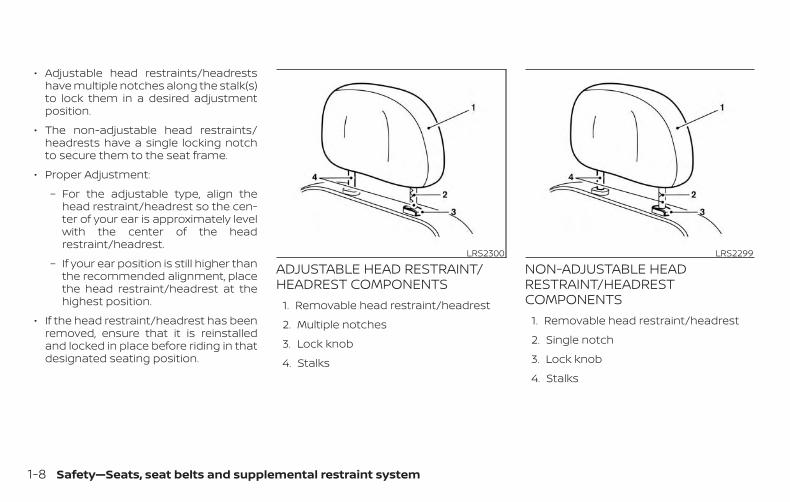
∙ Adjustable head restraints/headrestshave multiple notches along the stalk(s)to lock them in a desired adjustmentposition.
∙ The non-adjustable head restraints/headrests have a single locking notchto secure them to the seat frame.
∙ Proper Adjustment:
– For the adjustable type, align thehead restraint/headrest so the cen-ter of your ear is approximately levelwith the center of the headrestraint/headrest.
– If your ear position is still higher thanthe recommended alignment, placethe head restraint/headrest at thehighest position.
∙ If the head restraint/headrest has beenremoved, ensure that it is reinstalledand locked in place before riding in thatdesignated seating position.
ADJUSTABLE HEAD RESTRAINT/HEADREST COMPONENTS
1. Removable head restraint/headrest
2. Multiple notches
3. Lock knob
4. Stalks
NON-ADJUSTABLE HEADRESTRAINT/HEADRESTCOMPONENTS
1. Removable head restraint/headrest
2. Single notch
3. Lock knob
4. Stalks
LRS2300 LRS2299
1-8 Safety—Seats, seat belts and supplemental restraint system

REMOVEUse the following procedure to remove thehead restraint/headrest:
1. Pull the head restraint/headrest up tothe highest position.
2. Push and hold the lock knob.
3. Remove the head restraint/headrestfrom the seat.
4. Store the head restraint/headrestproperly in a secure place so it is notloose in the vehicle.
5. Reinstall and properly adjust the headrestraint/headrest before an occupantuses the seating position.
INSTALL1. Align the head restraint/headrest
stalks with the holes in the seat. Makesure that the head restraint/headrest isfacing the correct direction. The stalkwith the notch (notches) �1 must beinstalled in the hole with the lock knob�2 .
2. Push and hold the lock knob and pushthe head restraint/headrest down.
3. Properly adjust the head restraint/headrest before an occupant uses theseating position.
LRS2302 LRS2303
Safety—Seats, seat belts and supplemental restraint system 1-9

ADJUSTFor adjustable head restraint/headrest
Adjust the head restraint/headrest so thecenter is level with the center of your ears. Ifyour ear position is still higher than therecommended alignment, place the headrestraint/headrest at the highest position.
For non-adjustable head restraint/headrest
Make sure the head restraint/headrest ispositioned so the lock knob is engaged inthe notch before riding in that designatedseating position.
RaiseTo raise the head restraint/headrest, pull itup.
Make sure the head restraint/headrest ispositioned so the lock knob is engaged inthe notch before riding in that designatedseating position.
WRS0134 LRS2351 LRS2305
1-10 Safety—Seats, seat belts and supplemental restraint system
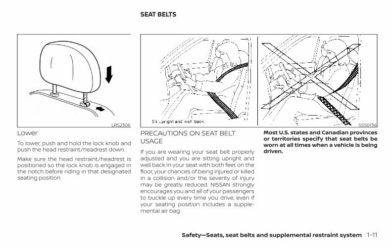
LowerTo lower, push and hold the lock knob andpush the head restraint/headrest down.
Make sure the head restraint/headrest ispositioned so the lock knob is engaged inthe notch before riding in that designatedseating position.
PRECAUTIONS ON SEAT BELTUSAGEIf you are wearing your seat belt properlyadjusted and you are sitting upright andwell back in your seat with both feet on thefloor, your chances of being injured or killedin a collision and/or the severity of injurymay be greatly reduced. NISSAN stronglyencourages you and all of your passengersto buckle up every time you drive, even ifyour seating position includes a supple-mental air bag.
Most U.S. states and Canadian provincesor territories specify that seat belts beworn at all times when a vehicle is beingdriven.
LRS2306 SSS0136
SEAT BELTS
Safety—Seats, seat belts and supplemental restraint system 1-11

WARNING∙ Every person who drives or rides in
this vehicle should use a seat belt atall times. Children should be in therear seats and in an appropriaterestraint.
WARNING∙ The seat belt should be properly ad-
justed to a snug fit. Failure to do somay reduce the effectiveness of theentire restraint system and increasethe chance or severity of injury in anaccident. Serious injury or death canoccur if the seat belt is not wornproperly.
SSS0134 SSS0016
1-12 Safety—Seats, seat belts and supplemental restraint system

WARNING∙ Always route the shoulder belt over
your shoulder and across your chest.Never put the belt behind your back,under your arm or across your neck.The belt should be away from yourface and neck, but not falling off yourshoulder.
∙ Position the lap belt as low and snugas possible AROUND THE HIPS, NOTTHE WAIST. A lap belt worn too highcould increase the risk of internal inju-ries in an accident.
∙ Be sure the seat belt tongue is se-curely fastened to the proper buckle.
∙ Do not wear the seat belt inside out ortwisted. Doing so may reduce itseffectiveness.
∙ Do not allow more than one person touse the same seat belt.
∙ Never carry more people in the vehiclethan there are seat belts.
∙ If the seat belt warning light glowscontinuously while the ignition isplaced in the ON position with alldoors closed and all seat belts fas-tened, it may indicate a malfunction inthe system. Have the system checked.It is recommended that you visit aNISSAN dealer for this service.
∙ No changes should be made to theseat belt system. For example, do notmodify the seat belt, add material, orinstall devices that may change theseat belt routing or tension. Doing somay affect the operation of the seatbelt system. Modifying or tamperingwith the seat belt system may resultin serious personal injury.
∙ Once seat belt pretensioner(s) haveactivated, they cannot be reused andmust be replaced together with theretractor. It is recommended that youvisit a NISSAN dealer for this service.
∙ All seat belt assemblies, including re-tractors and attaching hardware,should be inspected after any colli-sion. It is recommended that you visita NISSAN dealer for this service.NISSAN recommends that all seat beltassemblies in use during a collision bereplaced unless the collision was mi-nor and the belts show no damageand continue to operate properly.Seat belt assemblies not in use duringa collision should also be inspectedand replaced if either damage or im-proper operation is noted.
∙ All child restraints and attachinghardware should be inspected afterany collision. Always follow the re-straint manufacturer’s inspection in-structions and replacement recom-mendations. The child restraintsshould be replaced if they aredamaged.
SSS0014
Safety—Seats, seat belts and supplemental restraint system 1-13
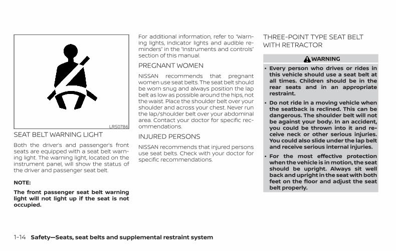
SEAT BELT WARNING LIGHTBoth the driver’s and passenger’s frontseats are equipped with a seat belt warn-ing light. The warning light, located on theinstrument panel, will show the status ofthe driver and passenger seat belt.
NOTE:
The front passenger seat belt warninglight will not light up if the seat is notoccupied.
For additional information, refer to “Warn-ing lights, indicator lights and audible re-minders” in the “Instruments and controls”section of this manual.
PREGNANT WOMENNISSAN recommends that pregnantwomen use seat belts. The seat belt shouldbe worn snug and always position the lapbelt as low as possible around the hips, notthe waist. Place the shoulder belt over yourshoulder and across your chest. Never runthe lap/shoulder belt over your abdominalarea. Contact your doctor for specific rec-ommendations.
INJURED PERSONSNISSAN recommends that injured personsuse seat belts. Check with your doctor forspecific recommendations.
THREE-POINT TYPE SEAT BELTWITH RETRACTOR
WARNING∙ Every person who drives or rides in
this vehicle should use a seat belt atall times. Children should be in therear seats and in an appropriaterestraint.
∙ Do not ride in a moving vehicle whenthe seatback is reclined. This can bedangerous. The shoulder belt will notbe against your body. In an accident,you could be thrown into it and re-ceive neck or other serious injuries.You could also slide under the lap beltand receive serious internal injuries.
∙ For the most effective protectionwhen the vehicle is in motion, the seatshould be upright. Always sit wellback and upright in the seat with bothfeet on the floor and adjust the seatbelt properly.
LRS0786
1-14 Safety—Seats, seat belts and supplemental restraint system
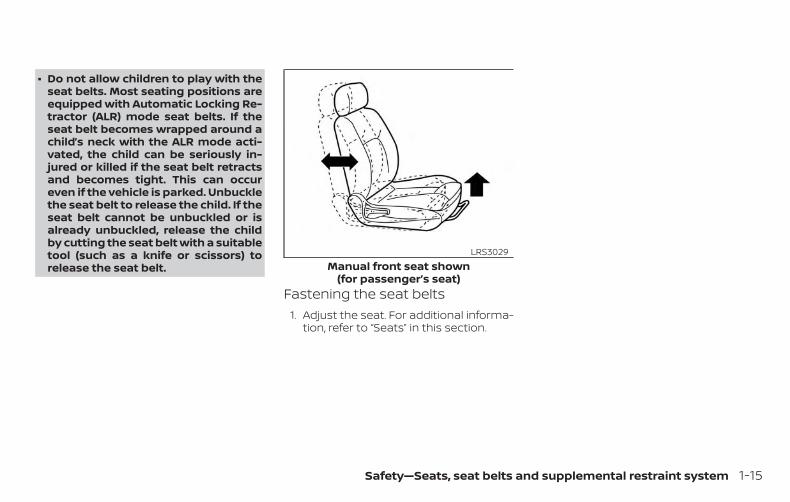
∙ Do not allow children to play with theseat belts. Most seating positions areequipped with Automatic Locking Re-tractor (ALR) mode seat belts. If theseat belt becomes wrapped around achild’s neck with the ALR mode acti-vated, the child can be seriously in-jured or killed if the seat belt retractsand becomes tight. This can occureven if the vehicle is parked. Unbucklethe seat belt to release the child. If theseat belt cannot be unbuckled or isalready unbuckled, release the childby cutting the seat belt with a suitabletool (such as a knife or scissors) torelease the seat belt.
Fastening the seat belts1. Adjust the seat. For additional informa-
tion, refer to “Seats” in this section.
Manual front seat shown(for passenger’s seat)
LRS3029
Safety—Seats, seat belts and supplemental restraint system 1-15

2. Slowly pull the seat belt out of the re-tractor and insert the tongue into thebuckle �A until you hear and feel thelatch engage.
∙ The retractor is designed to lockduring a sudden stop or on impact.A slow pulling motion permits theseat belt to move and allows yousome freedom of movement in theseat.
∙ If the seat belt cannot be pulledfrom its fully retracted position,firmly pull the belt and release it.Then smoothly pull the belt out ofthe retractor.
Power front seat shown (for driver’s seat)LRS2662 LRS2674
1-16 Safety—Seats, seat belts and supplemental restraint system

3. Position the lap belt portion low andsnug on the hips �B as shown.
4. Pull the shoulder belt portion towardthe retractor to take up extra slack �C .Be sure the shoulder belt is routed overyour shoulder and across your chest.
The front passenger seat and the rearseating positions’ three-point seat beltshave two modes of operation:
∙ Emergency Locking Retractor (ELR)
∙ Automatic Locking Retractor (ALR)
The ELR mode allows the seat belt to ex-tend and retract to allow the driver andpassengers some freedom of movementin the seat. The ELR locks the seat beltwhen the vehicle slows down rapidly orduring certain impacts.
The ALR mode (child restraint mode) locksthe seat belt for child restraint installation.
When the ALR mode is activated, the seatbelt cannot be extended again until theseat belt tongue is detached from thebuckle and fully retracted. The seat belt re-turns to the ELR mode after the seat beltfully retracts. For additional information, re-fer to “Child restraints” in this section.
The ALR mode should be used only forchild restraint installation. During nor-mal seat belt use by an occupant, the ALRmode should not be activated. If it is ac-tivated, it may cause uncomfortable seatbelt tension. It can also change the op-eration of the front passenger air bag.For additional information, refer to“Front passenger air bag and statuslight” in this section.
WARNINGWhen fastening the seat belts, be cer-tain that the seatbacks are completelysecured in the latched position. If theyare not completely secured, passengersmay be injured in an accident or suddenstop.
LRS2675
Safety—Seats, seat belts and supplemental restraint system 1-17

Unfastening the seat beltsTo unfasten the seat belt, press the buttonon the buckle �1 . The seat belt automati-cally retracts.
Checking seat belt operationSeat belt retractors are designed to lockseat belt movement by two separatemethods:
∙ When the seat belt is pulled quickly fromthe retractor
∙ When the vehicle slows down rapidly
To increase your confidence in the seatbelts, check the operation as follows:
∙ Grasp the shoulder belt and pull for-ward quickly. The retractor should lockand restrict further belt movement.
If the retractor does not lock during thischeck, get the system checked. It is recom-mended that you visit a NISSAN dealer forthis service or to learn more about seat beltoperation.
Shoulder belt height adjustment(front seats)The shoulder belt anchor height should beadjusted to the position best for you. Foradditional information, refer to “Precau-tions on seat belt usage” in this section. Toadjust, pull out the adjustment button �1and move the shoulder belt anchor to thedesired position �2 , so the belt passes overthe center of the shoulder. The belt shouldbe away from your face and neck, but notfalling off your shoulder. Release the ad-justment button to lock the shoulder beltanchor into position.
WRS0139 LRS0242
1-18 Safety—Seats, seat belts and supplemental restraint system
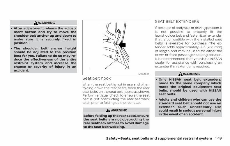
WARNING∙ After adjustment, release the adjust-
ment button and try to move theshoulder belt anchor up and down tomake sure it is securely fixed inposition.
∙ The shoulder belt anchor heightshould be adjusted to the positionbest for you. Failure to do so may re-duce the effectiveness of the entirerestraint system and increase thechance or severity of injury in anaccident.
Seat belt hookWhen the seat belt is not in use and whenfolding down the rear seats, hook the rearseat belts on the seat belt hooks as shown.Perform a visual check to ensure the seatbelt is not obstructing the rear seatbacklatch prior to folding up the rear seat.
WARNINGBefore folding up the rear seats, ensurethe seat belts are not obstructing therear seatback latches to avoid damageto the seat belt webbing.
SEAT BELT EXTENDERSIf, because of body size or driving position, itis not possible to properly fit thelap/shoulder belt and fasten it, an extenderthat is compatible with the installed seatbelts is available for purchase. The ex-tender adds approximately 8 in (200 mm)of length and may be used for either thedriver or front passenger seating position.It is recommended that you visit a NISSANdealer for assistance with purchasing anextender if an extender is required.
WARNING∙ Only NISSAN seat belt extenders,
made by the same company whichmade the original equipment seatbelts, should be used with NISSANseat belts.
∙ Adults and children who can use thestandard seat belt should not use anextender. Such unnecessary usecould result in serious personal injuryin the event of an accident.
LRS2851
Safety—Seats, seat belts and supplemental restraint system 1-19

∙ Never use seat belt extenders to in-stall child restraints. If the child re-straint is not secured properly, thechild could be seriously injured orkilled in a collision or a sudden stop.
SEAT BELT MAINTENANCE∙ To clean the seat belt webbing, apply
a mild soap solution or any solution rec-ommended for cleaning upholstery orcarpet. Then wipe with a cloth and allowthe seat belts to dry in the shade. Do notallow the seat belts to retract until theyare completely dry.
∙ If dirt builds up in the shoulder beltguide of the seat belt anchors, theseat belts may retract slowly. Wipe theshoulder belt guide with a clean, drycloth.
∙ Periodically check to see that the seatbelt and the metal components, suchas buckles, tongues, retractors, flexiblewires and anchors, work properly. Ifloose parts, deterioration, cuts or otherdamage on the webbing is found, theentire seat belt assembly should be re-placed.
WARNINGDo not allow children to play with theseat belts. Most seating positions areequipped with Automatic Locking Re-tractor (ALR) mode seat belts. If the seatbelt becomes wrapped around a child’sneck with the ALR mode activated, thechild can be seriously injured or killed ifthe seat belt retracts and becomestight. This can occur even if the vehicleis parked. Unbuckle the seat belt to re-lease the child. If the seat belt cannot beunbuckled or is already unbuckled, re-lease the child by cutting the seat beltwith a suitable tool (such as a knife orscissors) to release the seat belt.
Children need adults to help protectthem. They need to be properly re-strained.
In addition to the general information inthis manual, child safety information isavailable from many other sources, includ-ing doctors, teachers, government trafficsafety offices, and community organiza-tions. Every child is different, so be sure tolearn the best way to transport your child.
There are three basic types of child re-straint systems:
∙ Rear-facing child restraints
∙ Forward-facing child restraints
∙ Booster seats
The proper restraint depends on the child’ssize. Generally, infants up to about 1 yearand less than 20 lbs. (9 kg) should be placedin rear-facing child restraints. Forward-facing child restraints are available for chil-dren who outgrow rear-facing child re-straints and are at least 1 year old. Boosterseats are used to help position a vehiclelap/shoulder belt on a child who can nolonger use a forward-facing child restraint.
WARNINGInfants and children need special pro-tection. The vehicle’s seat belts may notfit them properly. The shoulder belt maycome too close to the face or neck. Thelap belt may not fit over their small hipbones. In an accident, an improperly fit-ting seat belt could cause serious or fa-tal injury. Always use appropriate childrestraints.
CHILD SAFETY
1-20 Safety—Seats, seat belts and supplemental restraint system
All U.S. states and Canadian provinces orterritories require the use of approved childrestraints for infants and small children. Foradditional information, refer to “Child re-straints” in this section.
A child restraint may be secured in the ve-hicle by using either the LATCH (Lower An-chors and Tethers for CHildren) system orwith the vehicle seat belt. For additionalinformation, refer to “Child restraints” in thissection.
NISSAN recommends that all pre-teensand children be restrained in the rearseat. Studies show that children aresafer when properly restrained in therear seat than in the front seat.
This is especially important becauseyour vehicle has a supplemental re-straint system (air bag system) for thefront passenger. For additional informa-tion, refer to “Supplemental RestraintSystem (SRS)” in this section.
INFANTSInfants up to at least 1 year old should beplaced in a rear-facing child restraint.NISSAN recommends that infants beplaced in child restraints that comply withFederal Motor Vehicle Safety Standards or
Canadian Motor Vehicle Safety Standards.You should choose a child restraint that fitsyour vehicle and always follow the manu-facturer’s instructions for installation anduse.
SMALL CHILDRENChildren that are over 1 year old and weighat least 20 lbs. (9 kg) should remain in arear-facing child restraint as long as pos-sible up to the height or weight limit of thechild restraint. Children who outgrow theheight or weight limit of the rear-facingchild restraint and are at least 1 year oldshould be secured in a forward-facing childrestraint with a harness. Refer to the manu-facturer’s instructions for minimum andmaximum weight and height recommen-dations. NISSAN recommends that smallchildren be placed in child restraints thatcomply with Federal Motor Vehicle SafetyStandards or Canadian Motor VehicleSafety Standards. You should choose achild restraint that fits your vehicle and al-ways follow the manufacturer’s instruc-tions for installation and use.
LARGER CHILDRENChildren should remain in a forward-facingchild restraint with a harness until theyreach the maximum height or weight limitallowed by the child restraint manufac-turer.
Once a child outgrows the height or weightlimit of the harness-equipped forward-facing child restraint, NISSAN recommendsthat the child be placed in a commerciallyavailable booster seat to obtain properseat belt fit. For a seat belt to fit properly, thebooster seat should raise the child so thatthe shoulder belt is properly positionedacross the chest and the top, middle por-tion of the shoulder. The shoulder beltshould not cross the neck or face andshould not fall off the shoulder. The lap beltshould lie snugly across the lower hips orupper thighs, not the abdomen. A boosterseat can only be used in seating positionsthat have a three-point type seat belt. Thebooster seat should fit the vehicle seat andhave a label certifying that it complies withFederal Motor Vehicle Safety Standards orCanadian Motor Vehicle Safety Standards.
Safety—Seats, seat belts and supplemental restraint system 1-21

A booster seat should be used until thechild can pass the seat belt fit test below:
∙ Are the child’s back and hips against thevehicle seatback?
∙ Is the child able to sit without slouch-ing?
∙ Do the child’s knees bend easily overthe front edge of the seat with feet flaton the floor?
∙ Can the child safely wear the seat belt(lap belt low and snug across the hipsand shoulder belt across mid-chestand shoulder)?
∙ Is the child able to use the properly ad-justed head restraint/headrest?
∙ Will the child be able to stay in positionfor the entire ride?
If you answered no to any of these ques-tions, the child should remain in a boosterseat using a three-point type seat belt.
NOTE:
Laws in some communities may followdifferent guidelines. Check local andstate regulations to confirm your child isusing the correct restraint system beforetraveling.
WARNINGNever let a child stand or kneel on anyseat and do not allow a child in thecargo area. The child could be seriouslyinjured or killed in a sudden stop orcollision.
LRS2690
1-22 Safety—Seats, seat belts and supplemental restraint system

PRECAUTIONS ON CHILDRESTRAINTS
WARNING∙ Failure to follow the warnings and in-
structions for proper use and installa-tion of child restraints could result inserious injury or death of a child orother passengers in a sudden stop orcollision:
– The child restraint must be usedand installed properly. Always fol-low all of the child restraint manu-facturer’s instructions for installa-tion and use.
– Infants and children should neverbe held on anyone’s lap. Even thestrongest adult cannot resist theforces of a collision.
– Do not put a seat belt around botha child and another passenger.
– NISSAN recommends that all childrestraints be installed in the rearseat. Studies show that childrenare safer when properly restrainedin the rear seat than in the frontseat. If you must install a forward-facing child restraint in the frontseat, refer to “Forward-facing childrestraint installation using the seatbelts” in this section.
– Even with the NISSAN Advanced AirBag System, never install a rear-facing child restraint in the frontseat. An inflating air bag could se-riously injure or kill a child. A rear-facing child restraint must only beused in the rear seat.
– Be sure to purchase a child re-straint that will fit the child and ve-hicle. Some child restraints maynot fit properly in your vehicle.
ARS1098 WRS0256
CHILD RESTRAINTS
Safety—Seats, seat belts and supplemental restraint system 1-23

– Child restraint anchorages are de-signed to withstand only thoseloads imposed by correctly fittedchild restraints. Under no circum-stances are they to be used to at-tach adult seat belts, or other itemsor equipment to the vehicle. Doingso could damage the child re-straint anchorages. The child re-straint will not be properly in-stalled using the damagedanchorage, and a child could be se-riously injured or killed in acollision.
– Never use the anchor points foradult seat belts, or other items.
– A child restraint with a top tetherstrap should not be used in thefront passenger seat.
– Keep seatbacks as upright as pos-sible after fitting the childrestraint.
– Infants and children should alwaysbe placed in an appropriate childrestraint while in the vehicle.
∙ When the child restraint is not in use,keep it secured with the LATCH systemor a seat belt. In a sudden stop or col-lision, loose objects can injure occu-pants or damage the vehicle.
CAUTIONA child restraint in a closed vehicle canbecome very hot. Check the seatingsurface and buckles before placing achild in the child restraint.
This vehicle is equipped with a universalchild restraint anchor system, referred toas the LATCH (Lower Anchors and Tethersfor CHildren) system. Some child restraintsinclude rigid or webbing-mounted attach-ments that can be connected to these an-chors. For additional information, refer to“LATCH (Lower Anchors and Tethers forCHildren) system” in this section.
If you do not have a LATCH compatiblechild restraint, the vehicle seat belts can beused.
Several manufacturers offer child re-straints for infants and children of varioussizes. When selecting any child restraint,keep the following points in mind:
∙ Choose only a restraint with a label cer-tifying that it complies with Federal Mo-tor Vehicle Safety Standard 213 or Cana-dian Motor Vehicle Safety Standard 213.
∙ Check the child restraint in your vehicleto be sure it is compatible with the vehi-cle’s seat and seat belt system.
∙ If the child restraint is compatible withyour vehicle, place your child in the childrestraint and check the various adjust-ments to be sure the child restraint iscompatible with your child. Choose achild restraint that is designed for yourchild’s height and weight. Always followall recommended procedures.
∙ If the combined weight of the child andchild restraint is less than 65 lbs.(29.5 kg), you may use either the LATCHanchors or the seat belt to install thechild restraint (not both at the sametime).
1-24 Safety—Seats, seat belts and supplemental restraint system

∙ If the combined weight of the child andchild restraint is greater than 65 lbs.(29.5 kg), use the vehicle’s seat belt (notthe lower anchors) to install the childrestraint.
∙ Be sure to follow the child restraintmanufacturer’s instructions for installa-tion.
All U.S. states and Canadian provinces orterritories require that infants and smallchildren be restrained in an approvedchild restraint at all times while the ve-hicle is being operated. Canadian law re-quires the top tether strap on forward-facing child restraints be secured to thedesignated anchor point on the vehicle.
LATCH (Lower Anchors andTethers for CHildren) SYSTEMYour vehicle is equipped with special an-chor points that are used with LATCH sys-tem compatible child restraints. This sys-tem may also be referred to as the ISOFIXor ISOFIX compatible system. With this sys-tem, you do not have to use a vehicle seatbelt to secure the child restraint unless thecombined weight of the child and child re-straint exceeds 65 lbs. (29.5 kg). If the com-bined weight of the child and child restraintis greater than 65 lbs. (29.5 kg), use the ve-
hicle’s seat belt (not the lower anchors) toinstall the child restraint. Be sure to followthe child restraint manufacturer’s instruc-tions for installation.
The LATCH lower anchor points are pro-vided to install child restraints in the follow-ing positions only:
∙ Rear bench seat – outboard seating po-sitions
LATCH lower anchor
WARNINGFailure to follow the warnings and in-structions for proper use and installa-tion of child restraints could result inserious injury or death of a child orother passengers in a sudden stop orcollision:
– Attach LATCH system compatiblechild restraints only at the loca-tions shown in the illustration.
– Do not secure a child restraint inthe rear bench center position us-ing the LATCH system anchors. Thechild restraint will not be securedproperly.
LATCH system lower anchor locations -bench seat
LRS2871
Safety—Seats, seat belts and supplemental restraint system 1-25
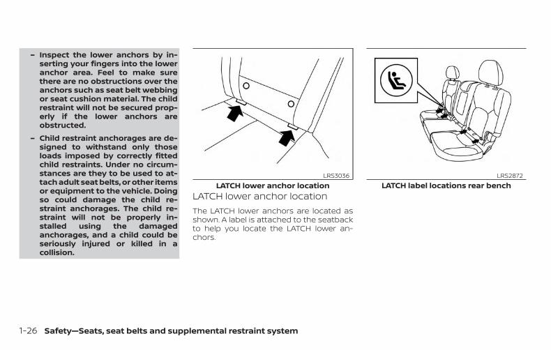
– Inspect the lower anchors by in-serting your fingers into the loweranchor area. Feel to make surethere are no obstructions over theanchors such as seat belt webbingor seat cushion material. The childrestraint will not be secured prop-erly if the lower anchors areobstructed.
– Child restraint anchorages are de-signed to withstand only thoseloads imposed by correctly fittedchild restraints. Under no circum-stances are they to be used to at-tach adult seat belts, or other itemsor equipment to the vehicle. Doingso could damage the child re-straint anchorages. The child re-straint will not be properly in-stalled using the damagedanchorages, and a child could beseriously injured or killed in acollision.
LATCH lower anchor locationThe LATCH lower anchors are located asshown. A label is attached to the seatbackto help you locate the LATCH lower an-chors.
LATCH lower anchor locationLRS3036
LATCH label locations rear benchLRS2872
1-26 Safety—Seats, seat belts and supplemental restraint system

Installing child restraint LATCHlower anchor attachmentsLATCH compatible child restraints includetwo rigid or webbing-mounted attach-ments that can be connected to two an-chors located at certain seating positionsin your vehicle. With this system, you do nothave to use a vehicle seat belt to secure thechild restraint. Check your child restraint fora label stating that it is compatible withLATCH. This information may also be in theinstructions provided by the child restraintmanufacturer.
When installing a child restraint, carefullyread and follow the instructions in thismanual and those supplied with the childrestraint.
Top tether anchor
WARNING∙ Do not allow cargo to contact the top
tether strap when it is attached to thetop tether anchor. Properly secure thecargo so it does not contact the toptether strap. Cargo that is not properlysecured or cargo that contacts the toptether strap may damage it during acollision. A child could be seriously in-jured or killed in a collision if the toptether strap is damaged.
∙ Child restraint anchorages are de-signed to withstand only those loadsimposed by correctly fitted child re-straints. Under no circumstances arethey to be used to attach adult seatbelts, or other items or equipment tothe vehicle. Doing so could damagethe child restraint anchorages. Thechild restraint will not be properly in-stalled using the damaged anchor-ages, and a child could be seriouslyinjured or killed in a collision.
LATCH webbing-mounted attachmentLRS0661
LATCH rigid-mounted attachmentLRS0662
Safety—Seats, seat belts and supplemental restraint system 1-27

�1 Top tether strap
�2 Anchor point
Top tether anchor point locationsAnchor points are located in the followinglocations:
∙ Rear bench on the bottom of the seat-back in the seating positions shown.
∙ Roof above the rear cargo area.
The top tether anchor located in the roof isonly to be used for a child restraint locatedin the center position of the rear benchseat.
If you have any questions when installing atop tether strap, it is recommended thatyou visit a NISSAN dealer for this service.
REAR-FACING CHILD RESTRAINTINSTALLATION USING LATCHFor additional information, refer to all Warn-ings and Cautions in the “Child safety” and“Child restraints” sections of this manualbefore installing a child restraint.
Do not use the lower anchors if the com-bined weight of the child and the child re-straint exceeds 65 lbs. (29.5 kg). If the com-bined weight of the child and the childrestraint is greater than 65 lbs. (29.5 kg), usethe vehicle’s seat belt (not the lower an-chors) to install the child restraint. Be sureto follow the child restraint manufacturer’sinstructions for installation.
Follow these steps to install a rear-facingchild restraint in the rear bench seats usingthe LATCH system:
1. Position the child restraint on the seat.Always follow the child restraint manu-facturer’s instructions.
Rear bench seatLRS2714
1-28 Safety—Seats, seat belts and supplemental restraint system

2. Secure the child restraint anchor at-tachments to the LATCH lower an-chors. Check to make sure the LATCHattachment is properly attached to thelower anchors.
3. For child restraints that are equippedwith webbing-mounted attachments,remove any additional slack from theanchor attachments. Press downwardand rearward firmly in the center of thechild restraint with your hand to com-press the vehicle seat cushion andseatback while tightening the webbingof the anchor attachments.
Rear-facing webbing-mounted – step 2LRS2997
Rear-facing rigid-mounted – step 2LRS2996
Rear-facing – step 3LRS0673
Safety—Seats, seat belts and supplemental restraint system 1-29
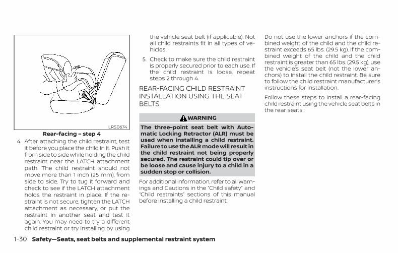
4. After attaching the child restraint, testit before you place the child in it. Push itfrom side to side while holding the childrestraint near the LATCH attachmentpath. The child restraint should notmove more than 1 inch (25 mm), fromside to side. Try to tug it forward andcheck to see if the LATCH attachmentholds the restraint in place. If the re-straint is not secure, tighten the LATCHattachment as necessary, or put therestraint in another seat and test itagain. You may need to try a differentchild restraint or try installing by using
the vehicle seat belt (if applicable). Notall child restraints fit in all types of ve-hicles.
5. Check to make sure the child restraintis properly secured prior to each use. Ifthe child restraint is loose, repeatsteps 2 through 4.
REAR-FACING CHILD RESTRAINTINSTALLATION USING THE SEATBELTS
WARNINGThe three-point seat belt with Auto-matic Locking Retractor (ALR) must beused when installing a child restraint.Failure to use the ALR mode will result inthe child restraint not being properlysecured. The restraint could tip over orbe loose and cause injury to a child in asudden stop or collision.
For additional information, refer to all Warn-ings and Cautions in the “Child safety” and“Child restraints” sections of this manualbefore installing a child restraint.
Do not use the lower anchors if the com-bined weight of the child and the child re-straint exceeds 65 lbs. (29.5 kg). If the com-bined weight of the child and the childrestraint is greater than 65 lbs. (29.5 kg), usethe vehicle’s seat belt (not the lower an-chors) to install the child restraint. Be sureto follow the child restraint manufacturer’sinstructions for installation.
Follow these steps to install a rear-facingchild restraint using the vehicle seat belts inthe rear seats:
Rear-facing – step 4LRS0674
1-30 Safety—Seats, seat belts and supplemental restraint system

1. Child restraints for infants must beused in the rear-facing direction andtherefore must not be used in thefront seat. Position the child restrainton the seat. Always follow the child re-straint manufacturer’s instructions.
2. Route the seat belt tongue through thechild restraint and insert it into thebuckle until you hear and feel the latchengage. Be sure to follow the child re-straint manufacturer’s instructions forbelt routing.
3. Pull the shoulder belt until the belt isfully extended. At this time, the seat beltretractor is in the ALR mode (child re-straint mode). It reverts to the ELRmode when the seat belt is fully re-tracted.
Rear-facing – step 1WRS0256
Rear-facing – step 2WRS0761
Rear-facing – step 3LRS2395
Safety—Seats, seat belts and supplemental restraint system 1-31

4. Allow the seat belt to retract. Pull up onthe shoulder belt to remove any slackin the belt.
5. Remove any additional slack from theseat belt; press downward and rear-ward firmly in the center of the childrestraint to compress the vehicle seatcushion and seatback while pulling upon the seat belt.
6. After attaching the child restraint, testit before you place the child in it. Push itfrom side to side while holding the childrestraint near the seat belt path. Thechild restraint should not move morethan 1 inch (25 mm), from side to side.Try to tug it forward and check to see ifthe belt holds the restraint in place. Ifthe restraint is not secure, tighten theseat belt as necessary, or put the re-straint in another seat and test it again.You may need to try a different childrestraint. Not all child restraints fit in alltypes of vehicles.
Rear-facing – step 4LRS2396
Rear-facing – step 5WRS0762
Rear-facing – step 6LRS2397
1-32 Safety—Seats, seat belts and supplemental restraint system

7. Check to make sure that the child re-straint is properly secured prior to eachuse. If the seat belt is not locked, repeatsteps 3 through 6.
After the child restraint is removed and theseat belt fully retracted, the ALR mode(child restraint mode) is canceled.
FORWARD-FACING CHILDRESTRAINT INSTALLATION USINGLATCHFor additional information, refer to all Warn-ings and Cautions in the “Child safety” and“Child restraints” sections of this manualbefore installing a child restraint.
Do not use the lower anchors if the com-bined weight of the child and the child re-straint exceeds 65 lbs. (29.5 kg). If the com-bined weight of the child and the childrestraint is greater than 65 lbs. (29.5 kg), usethe vehicle’s seat belt (not the lower an-chors) to install the child restraint. Be sureto follow the child restraint manufacturer’sinstructions for installation.
Follow these steps to install a forward-facing child restraint in the rear benchseats using the LATCH system:
1. Position the child restraint on the seat.Always follow the child restraint manu-facturer’s instructions.
Forward-facing webbing-mounted –step 2
LRS2995
Safety—Seats, seat belts and supplemental restraint system 1-33

2. Secure the child restraint anchor at-tachments to the LATCH lower an-chors. Check to make sure the LATCHattachment is properly attached to thelower anchors.
If the child restraint is equipped with atop tether strap, route the top tetherstrap and secure the tether strap tothe tether anchor point. For additionalinformation, refer to “Installing toptether strap” in this section.
Do not install child restraints that re-quire the use of a top tether strap inseating positions that do not have atop tether anchor.
3. The back of the child restraint shouldbe secured against the vehicle seat-back.
If necessary, adjust or remove the headrestraint/headrest to obtain the cor-rect child restraint fit. If the headrestraint/headrest is removed, store itin a secure place. Be sure to reinstallthe head restraint/headrest whenthe child restraint is removed. For ad-ditional information, refer to “Headrestraints/headrests” in this section.
If the seating position does not havean adjustable head restraint/headrestand it is interfering with the properchild restraint fit, try another seatingposition or a different child restraint.
4. For child restraints that are equippedwith webbing-mounted attachments,remove any additional slack from theanchor attachments. Press downwardand rearward firmly in the center of thechild restraint with your knee to com-press the vehicle seat cushion andseatback while tightening the webbingof the anchor attachments.
5. Tighten the tether strap according tothe manufacturer’s instructions to re-move any slack.
Forward-facing rigid-mounted – step 2LRS2994
Forward-facing – step 4LRS0671
1-34 Safety—Seats, seat belts and supplemental restraint system

6. After attaching the child restraint, testit before you place the child in it. Push itfrom side to side while holding the childrestraint near the LATCH attachmentpath. The child restraint should notmove more than 1 inch (25 mm), fromside to side. Try to tug it forward andcheck to see if the LATCH attachmentholds the restraint in place. If the re-straint is not secure, tighten the LATCHattachment as necessary, or put therestraint in another seat and test itagain. You may need to try a differentchild restraint. Not all child restraints fitin all types of vehicles.
7. Check to make sure the child restraintis properly secured prior to each use. Ifthe child restraint is loose, repeatsteps 2 through 6.
�1 Top tether strap
�2 Anchor point
Installing top tether strapThe child restraint top tether strap must beused when installing the child restraint withthe LATCH lower anchor attachments.
First, secure the child restraint with theLATCH lower anchors (rear outboard posi-tions only).
Forward-facing – step 6WRS0697
Rear seatsLRS3041
Safety—Seats, seat belts and supplemental restraint system 1-35

Rear bench seat
OUTBOARD SEATING POSITIONS
1. Remove the head restraint/headrestand store it in a secure place. Be sure toreinstall the head restraint/headrestwhen the child restraint is removed. Foradditional information, refer to “Headrestraints/headrests” in this section.
2. Position the top tether strap �1 asshown.
3. Secure the tether strap to the tetheranchor point �2 as shown.
4. Tighten the tether strap according tothe manufacturer’s instructions to re-move any slack.
If you have any questions when install-ing a top tether strap, it is recommendedthat you visit a NISSAN dealer for thisservice.
WARNINGChild restraint anchorages are de-signed to withstand only those loadsimposed by correctly fitted child re-straints. Under no circumstances arethey to be used to attach adult seatbelts, or other items or equipment tothe vehicle. Doing so could damage thechild restraint anchorages. The child re-straint will not be properly installed us-ing the damaged anchorage, and achild could be seriously injured or killedin a collision.
FORWARD-FACING CHILDRESTRAINT INSTALLATION USINGTHE SEAT BELTS
WARNINGThe three-point seat belt with Auto-matic Locking Retractor (ALR) must beused when installing a child restraint.Failure to use the ALR mode will result inthe child restraint not being properlysecured. The restraint could tip over orbe loose and cause injury to a child in asudden stop or collision. Also, it canchange the operation of the front pas-senger air bag. For additional informa-tion, refer to “Front passenger air bagand status light” in this section.
1-36 Safety—Seats, seat belts and supplemental restraint system

For additional information, refer to all Warn-ings and Cautions in the “Child safety” and“Child restraints” sections of this manualbefore installing a child restraint.
Do not use the lower anchors if the com-bined weight of the child and the child re-straint exceeds 65 lbs. (29.5 kg). If the com-bined weight of the child and the childrestraint is greater than 65 lbs. (29.5 kg), usethe vehicle’s seat belt (not the lower an-chors) to install the child restraint. Be sureto follow the child restraint manufacturer’sinstructions for installation.
Follow these steps to install a forward-facing child restraint using the vehicle seatbelt in the rear seats or in the front passen-ger seat:
1. If you must install a child restraint inthe front seat, it should be placed in aforward-facing direction only. Movethe seat to the rearmost position.Child restraints for infants must beused in the rear-facing direction and,therefore, must not be used in thefront seat.
2. Position the child restraint on the seat.Always follow the child restraint manu-facturer’s instructions.
The back of the child restraint shouldbe secured against the vehicle seat-back.
If necessary, adjust or remove the headrestraint/headrest to obtain the cor-rect child restraint fit. If the headrestraint/headrest is removed, store itin a secure place. Be sure to reinstallthe head restraint/headrest whenthe child restraint is removed. For ad-ditional information, refer to “Headrestraints/headrests” in this section.
If the seating position does not havean adjustable head restraint/headrestand it is interfering with the properchild restraint fit, try another seatingposition or a different child restraint.
Forward-facing (front passenger seat) –step 1
WRS0699
Safety—Seats, seat belts and supplemental restraint system 1-37

3. Route the seat belt tongue through thechild restraint and insert it into thebuckle until you hear and feel the latchengage. Be sure to follow the child re-straint manufacturer’s instructions forbelt routing.
If the child restraint is equipped with atop tether strap, route the top tetherstrap and secure the tether strap tothe tether anchor point (rear seat in-stallation only). For additional informa-tion, refer to “Installing top tether strap”in this section.
Do not install child restraints that re-quire the use of a top tether strap inseating positions that do not have atop tether anchor.
4. Pull the shoulder belt until the belt isfully extended. At this time, the seat beltretractor is in the ALR mode (child re-straint mode). It reverts to ELR modewhen the seat belt is fully retracted.
Forward-facing – step 3WRS0680
Forward-facing – step 4LRS2394
1-38 Safety—Seats, seat belts and supplemental restraint system

5. Allow the seat belt to retract. Pull up onthe shoulder belt to remove any slackin the belt.
6. Remove any additional slack from theseat belt; press downward and rear-ward firmly in the center of the childrestraint with your knee to compressthe vehicle seat cushion and seatbackwhile pulling up on the seat belt.
7. Tighten the tether strap according tothe manufacturer’s instructions to re-move any slack.
8. After attaching the child restraint, testit before you place the child in it. Push itfrom side to side while holding the childrestraint near the seat belt path. Thechild restraint should not move morethan 1 inch (25 mm), from side to side.Try to tug it forward and check to see ifthe belt holds the restraint in place. Ifthe restraint is not secure, tighten theseat belt as necessary, or put the re-straint in another seat and test it again.You may need to try a different childrestraint. Not all child restraints fit in alltypes of vehicles.
Forward-facing – step 5LRS0668
Forward-facing – step 6WRS0681
Forward-facing – step 8WRS0698
Safety—Seats, seat belts and supplemental restraint system 1-39
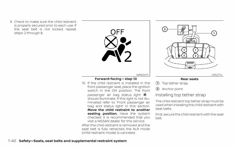
9. Check to make sure the child restraintis properly secured prior to each use. Ifthe seat belt is not locked, repeatsteps 2 through 8.
10. If the child restraint is installed in thefront passenger seat, place the ignitionswitch in the ON position. The frontpassenger air bag status lightshould illuminate. If this light is not illu-minated refer to “Front passenger airbag and status light” in this section.Move the child restraint to anotherseating position. Have the systemchecked. It is recommended that youvisit a NISSAN dealer for this service.
After the child restraint is removed and theseat belt is fully retracted, the ALR mode(child restraint mode) is canceled.
�1 Top tether strap
�2 Anchor point
Installing top tether strapThe child restraint top tether strap must beused when installing the child restraint withseat belts.
First, secure the child restraint with the seatbelt.
Forward-facing – step 10WRS0475
Rear seatsLRS2714
1-40 Safety—Seats, seat belts and supplemental restraint system
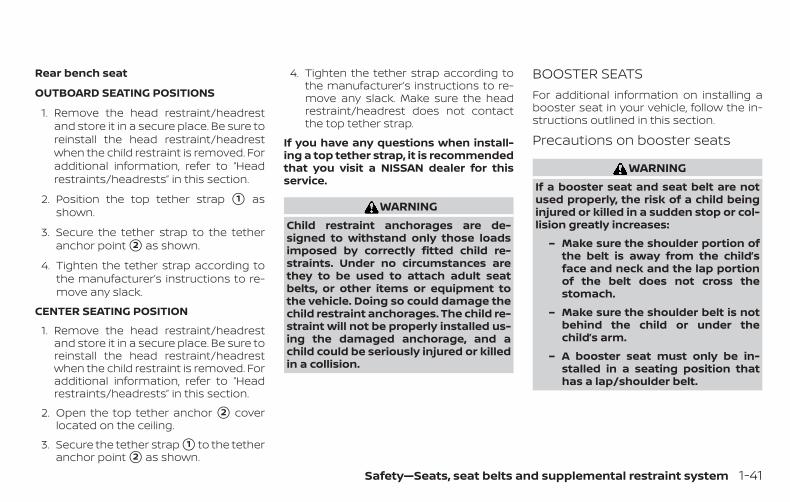
Rear bench seat
OUTBOARD SEATING POSITIONS
1. Remove the head restraint/headrestand store it in a secure place. Be sure toreinstall the head restraint/headrestwhen the child restraint is removed. Foradditional information, refer to “Headrestraints/headrests” in this section.
2. Position the top tether strap �1 asshown.
3. Secure the tether strap to the tetheranchor point �2 as shown.
4. Tighten the tether strap according tothe manufacturer’s instructions to re-move any slack.
CENTER SEATING POSITION
1. Remove the head restraint/headrestand store it in a secure place. Be sure toreinstall the head restraint/headrestwhen the child restraint is removed. Foradditional information, refer to “Headrestraints/headrests” in this section.
2. Open the top tether anchor �2 coverlocated on the ceiling.
3. Secure the tether strap �1 to the tetheranchor point �2 as shown.
4. Tighten the tether strap according tothe manufacturer’s instructions to re-move any slack. Make sure the headrestraint/headrest does not contactthe top tether strap.
If you have any questions when install-ing a top tether strap, it is recommendedthat you visit a NISSAN dealer for thisservice.
WARNINGChild restraint anchorages are de-signed to withstand only those loadsimposed by correctly fitted child re-straints. Under no circumstances arethey to be used to attach adult seatbelts, or other items or equipment tothe vehicle. Doing so could damage thechild restraint anchorages. The child re-straint will not be properly installed us-ing the damaged anchorage, and achild could be seriously injured or killedin a collision.
BOOSTER SEATSFor additional information on installing abooster seat in your vehicle, follow the in-structions outlined in this section.
Precautions on booster seats
WARNINGIf a booster seat and seat belt are notused properly, the risk of a child beinginjured or killed in a sudden stop or col-lision greatly increases:
– Make sure the shoulder portion ofthe belt is away from the child’sface and neck and the lap portionof the belt does not cross thestomach.
– Make sure the shoulder belt is notbehind the child or under thechild’s arm.
– A booster seat must only be in-stalled in a seating position thathas a lap/shoulder belt.
Safety—Seats, seat belts and supplemental restraint system 1-41

A. Low back booster seatB. High back booster seat
Booster seats of various sizes are offeredby several manufacturers. When selectingany booster seat, keep the following pointsin mind:
∙ Choose only a booster seat with a labelcertifying that it complies with FederalMotor Vehicle Safety Standard 213 orCanadian Motor Vehicle Safety Stan-dard 213.
∙ Check the booster seat in your vehicleto be sure it is compatible with the vehi-cle’s seat and seat belt system.
∙ Make sure the child’s head will be prop-erly supported by the booster seat orvehicle seat. The seatback must be ator above the center of the child’s ears.For example, if a low back booster seatis chosen, the vehicle seatback must beat or above the center of the child’s ears.If the seatback is lower than the centerof the child’s ears, a high back boosterseat should be used.
LRS2479 LRS0453 LRS0464
1-42 Safety—Seats, seat belts and supplemental restraint system

∙ If the booster seat is compatible withyour vehicle, place the child in thebooster seat and check the various ad-justments to be sure the booster seat iscompatible with the child. Always followall recommended procedures.
All U.S. states and Canadian provinces orterritories require that infants and smallchildren be restrained in an approvedchild restraint at all times while the ve-hicle is being operated.
The instructions in this section apply tobooster seat installation in the rear seatsor the front passenger seat.
Booster seat installation
WARNINGTo avoid injury to child, do not use thelap/shoulder belt in the AutomaticLocking Retractor (ALR) mode when us-ing a booster seat with the seat belts.
For additional information, refer to all Warn-ings and Cautions in the “Child safety”,“Child restraints” and “Booster seats” sec-tions of this manual before installing a childrestraint.
Follow these steps to install a booster seatin the rear seat or in the front passengerseat:
1. If you must install a booster seat inthe front seat, move the seat to therearmost position.
2. Position the booster seat on the seat.Only place it in a front-facing direction.Always follow the booster seat manu-facturer’s instructions.
WRS0699
Safety—Seats, seat belts and supplemental restraint system 1-43

3. The booster seat should be positionedon the vehicle seat so that it is stable.
If necessary, adjust or remove the headrestraint/headrest to obtain the cor-rect booster seat fit. If the headrestraint/headrest is removed, store itin a secure place. Be sure to reinstallthe head restraint/headrest whenthe booster seat is removed. For ad-ditional information, refer to "Headrestraints/headrests" in this section.
If the seating position does not havean adjustable head restraint/headrestand it is interfering with the proper
booster seat fit, try another seatingposition or a different booster seat.
4. Position the lap portion of the seat beltlow and snug on the child’s hips. Besure to follow the booster seat manu-facturer’s instructions for adjusting theseat belt routing.
5. Pull the shoulder belt portion of theseat belt toward the retractor to takeup extra slack. Be sure the shoulderbelt is positioned across the top,middle portion of the child’s shoulder.Be sure to follow the booster seatmanufacturer’s instructions for adjust-ing the seat belt routing.
6. Follow the warnings, cautions and in-structions for properly fastening a seatbelt shown in “Three-point type seatbelt with retractor” in this section.
7. If the booster seat is installed in thefront passenger seat, place the ignitionswitch in the ON position. The front pas-senger air bag status light may ormay not illuminate, depending on thesize of the child and the type of boosterseat being used. For additional infor-mation, refer to “Front passenger airbag and status light” in this section.
Front passenger positionLRS0454 WRS0475
1-44 Safety—Seats, seat belts and supplemental restraint system

PRECAUTIONS ON SRSThis SRS section contains important infor-mation concerning the following systems:
∙ Driver and front passenger supplemen-tal front-impact air bag (NISSAN Ad-vanced Air Bag System)
∙ Front seat-mounted side-impactsupplemental air bag
∙ Roof-mounted curtain side-impact androllover supplemental air bag
∙ Seat belt with pretensioner(s) (frontseats)
Supplemental front-impact air bag sys-tem
The NISSAN Advanced Air Bag System canhelp cushion the impact force to the headand chest of the driver and front passengerin certain frontal collisions.
Front seat-mounted side-impactsupplemental air bag system
This system can help cushion the impactforce to the chest area of the driver andfront passenger in certain side-impact col-lisions. The side air bags are designed toinflate on the side where the vehicle is im-pacted.
Roof-mounted curtain side-impact androllover supplemental air bag system
This system can help cushion the impactforce to the head of occupants in front andrear outboard seating positions in certainside-impact collisions. The curtain air bagsare designed to inflate on the side wherethe vehicle is impacted. In a rollover, thecurtain air bags are designed to inflate andremain inflated for a short time.
The SRS is designed to supplement thecrash protection provided by the driver andfront passenger seat belts and is not asubstitute for them. Seat belts should al-ways be correctly worn and the occupantseated a suitable distance away from thesteering wheel, instrument panel and doorfinishers. For additional information, referto “Seat belts” in this section.
The supplemental air bags operate onlywhen the ignition switch is placed in theON position.
After placing the ignition switch in theON position, the supplemental air bagwarning light illuminates. The supple-mental air bag warning light will turn offafter about 7 seconds if the system isoperational.
SUPPLEMENTAL RESTRAINT SYSTEM(SRS)
Safety—Seats, seat belts and supplemental restraint system 1-45

WARNING∙ The front air bags ordinarily will not
inflate in the event of a side impact,rear impact, rollover, or lower severityfrontal collision. Always wear yourseat belts to help reduce the risk orseverity of injury in various kinds ofaccidents
∙ The front passenger air bag will notinflate if the passenger air bag statuslight is lit. For additional information,refer to “Front passenger air bag andstatus light” in this section.
∙ The seat belts and the front air bagsare most effective when you are sit-ting well back and upright in the seat.The front air bags inflate with greatforce. Even with the NISSAN AdvancedAir Bag System, if you are unre-strained, leaning forward, sitting side-ways or out of position in any way, youare at greater risk of injury or death ina crash. You may also receive seriousor fatal injuries from the front air bagif you are up against it when it inflates.Always sit back against the seatback
and as far away as practical from thesteering wheel or instrument panel.Always properly use the seat belts.
∙ The driver and front passenger seatbelt buckles are equipped with sensorsthat detect if the seat belts are fas-tened. The NISSAN Advanced Air BagSystem monitors the severity of a colli-sion and seat belt usage, then inflatesthe air bags as needed. Failure to prop-erly wear seat belts can increase therisk or severity of injury in an accident.
∙ The front passenger seat is equippedwith an occupant classification sen-sor (weight sensor) that turns thefront passenger air bag OFF undersome conditions. This sensor is onlyused in this seat. Failure to be properlyseated and wearing the seat belt canincrease the risk or severity of injury inan accident. For additional informa-tion, refer to “Front passenger air bagand status light” in this section.
∙ Keep hands on the outside of thesteering wheel. Placing them insidethe steering wheel rim could increasethe risk that they are injured when thefront air bag inflates.
WRS0031
1-46 Safety—Seats, seat belts and supplemental restraint system

WARNING∙ Never let children ride unrestrained or
extend their hands or face out of thewindow. Do not attempt to hold themin your lap or arms. Some examples ofdangerous riding positions are shownin the illustrations.
ARS1133 ARS1041
Safety—Seats, seat belts and supplemental restraint system 1-47
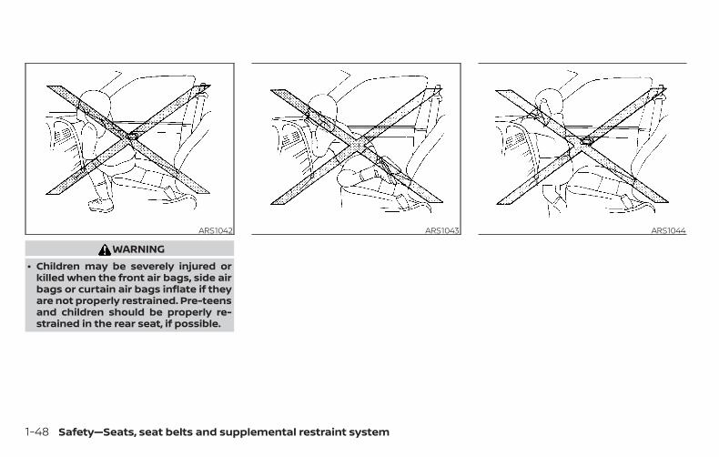
WARNING∙ Children may be severely injured or
killed when the front air bags, side airbags or curtain air bags inflate if theyare not properly restrained. Pre-teensand children should be properly re-strained in the rear seat, if possible.
ARS1042 ARS1043 ARS1044
1-48 Safety—Seats, seat belts and supplemental restraint system

WARNING∙ Even with the NISSAN Advanced Air
Bag System, never install a rear-facing child restraint in the front seat.An inflating front air bag could seri-ously injure or kill your child. For addi-tional information, refer to “Child re-straints” in this section.
WARNINGFront seat-mounted side-impactsupplemental air bags and roof-mounted curtain side-impact and roll-over supplemental air bags:
∙ The side air bags and curtain air bagsordinarily will not inflate in the eventof a frontal impact, rear impact, orlower severity side collision. Alwayswear your seat belts to help reducethe risk or severity of injury in variouskinds of accidents.
ARS1045 ARS1046 WRS0431
Safety—Seats, seat belts and supplemental restraint system 1-49

WARNING∙ The seat belts, the side air bags and
curtain air bags are most effectivewhen you are sitting well back andupright in the seat with both feet onthe floor. The side air bag and curtainair bag inflate with great force. Do notallow anyone to place their hand, legor face near the side air bag on theside of the seatback of the front seator near the side roof rails. Do not allowanyone sitting in the front seats orrear outboard seats to extend theirhand out of the window or leanagainst the door. Some examples ofdangerous riding positions are shownin the previous illustrations.
WARNING∙ When sitting in the rear seat, do not
hold onto the seatback of the frontseat. If the side air bag inflates, youmay be seriously injured. Be espe-cially careful with children, whoshould always be properly restrained.Some examples of dangerous ridingpositions are shown in theillustrations.
∙ Do not use seat covers on the frontseatbacks. They may interfere withside air bag inflation.
LRS3119 WRS0032
1-50 Safety—Seats, seat belts and supplemental restraint system

SSS0162 SSS0159
Safety—Seats, seat belts and supplemental restraint system 1-51

NISSAN Advanced Air Bag System(front seats)
1. Supplemental front-impact air bagmodules
2. Air bag Control Unit (ACU)
3. Occupant classification sensor (weightsensor)
4. Front seat-mounted side-impactsupplemental air bag modules
5. Roof-mounted curtain side-impactand rollover supplemental air bags
6. Roof-mounted curtain side-impactand rollover supplemental air bag infla-tors
7. Satellite sensors
8. Seat belt with pretensioner(s) (frontseats)
9. Pressure sensors in door (driver’s sideshown; front passenger side similar)
10. Crash zone sensor
LRS2817
1-52 Safety—Seats, seat belts and supplemental restraint system

WARNINGTo ensure proper operation of the pas-senger’s NISSAN Advanced Air Bag Sys-tem, please observe the followingitems.
∙ Do not allow a passenger in the rearbench seats to push or pull on theseatback pocket.
∙ Do not place heavy loads heavier than9.1 lbs. (4 kg) on the seatback, headrestraint/headrest or in the seatbackpocket.
∙ Make sure that there is nothing press-ing against the rear of the seatback,such as a child restraint installed inthe rear seat or an object stored onthe floor.
∙ Make sure that there is no objectplaced under the front passengerseat.
∙ Make sure that there is no objectplaced between the seat cushion andcenter console or between the seatcushion and the door.
∙ If a forward-facing child restraint isinstalled in the front passenger seat,do not position the front passengerseat so the child restraint contacts theinstrument panel. If the child restraintdoes contact the instrument panel,the system may determine the seat isoccupied and the passenger air bagmay deploy in a collision. Also thefront passenger air bag status lightmay not illuminate. For additional in-formation, refer to “Child restraints” inthis section.
∙ Confirm the operating condition withthe front passenger air bag statuslight.
∙ If you notice that the front passengerair bag status light is not operating asdescribed in this section, get the oc-cupant classification system checked.It is recommended that you visit aNISSAN dealer for this service.
∙ Until you have confirmed with adealer that your passenger seat occu-pant classification system is workingproperly, position the occupants inthe rear seating positions.
∙ Do not position the front passengerseat so it contacts the rear seat. If thefront seat does contact the rear seat,the air bag system may determine asensor malfunction has occurred andthe front passenger air bag statuslight may illuminate and the supple-mental air bag warning light mayflash.
This vehicle is equipped with the NISSANAdvanced Air Bag System for the driver andfront passenger seats. This system is de-signed to meet certification requirementsunder U.S. regulations. It is also permitted inCanada. However, all of the information,cautions and warnings in this manualstill apply and must be followed.
The driver supplemental front-impact airbag is located in the center of the steeringwheel. The front passenger supplementalfront-impact air bag is mounted in thedashboard above the glove box. The frontair bags are designed to inflate in higherseverity frontal collisions, although theymay inflate if the forces in another type ofcollision are similar to those of a higherseverity frontal impact. They may not in-flate in certain frontal collisions. Vehicle
Safety—Seats, seat belts and supplemental restraint system 1-53

damage (or lack of it) is not always an indi-cation of proper front air bag system op-eration.
The NISSAN Advanced Air Bag Systemmonitors information from the crash zonesensor, the Air bag Control Unit (ACU), seatbelt buckle sensors and occupation classi-fication sensor (weight sensor). Inflator op-eration is based on the severity of a colli-sion and seat belt usage for the driver. Forthe front passenger, the occupant classifi-cation sensor is also monitored. Based oninformation from the sensor, only one frontair bag may inflate in a crash, depending onthe crash severity and whether the frontoccupants are belted or unbelted. Addi-tionally, the front passenger air bag may beautomatically turned off under some con-ditions, depending on the weight detectedon the front passenger seat and how theseat belt is used. If the front passenger airbag is OFF, the front passenger air bag sta-tus light will be illuminated. For additionalinformation, refer to “Front passenger airbag and status light” in this section. Onefront air bag inflating does not indicate im-proper performance of the system.
If you have any questions about your airbag system, it is recommended that youvisit a NISSAN dealer to obtain informationabout the system. If you are consideringmodification of your vehicle due to a dis-ability, you may also contact NISSAN. Con-tact information is contained in the front ofthis Owner’s Manual.
When a front air bag inflates, a fairly loudnoise may be heard, followed by the re-lease of smoke. This smoke is not harmfuland does not indicate a fire. Care should betaken to not inhale it, as it may cause irrita-tion and choking. Those with a history of abreathing condition should get fresh airpromptly.
Front air bags, along with the use of seatbelts, help to cushion the impact force onthe face and chest of the front occupants.They can help save lives and reduce seri-ous injuries. However, an inflating front airbag may cause facial abrasions or otherinjuries. Front air bags do not provide re-straint to the lower body.
Even with NISSAN Advanced Air Bags, seatbelts should be correctly worn and thedriver and front passenger seated uprightas far as practical away from the steeringwheel or instrument panel. The front airbags inflate quickly in order to help protectthe front occupants. Because of this, theforce of the front air bag inflating can in-crease the risk of injury if the occupant istoo close to, or is against, the front air bagmodule during inflation.
The front air bags deflate quickly after acollision.
The front air bags operate only when theignition switch is in the ON position.
After placing the ignition switch in theON position, the supplemental air bagwarning light illuminates. The supple-mental air bag warning light will turn offafter about 7 seconds if the system isoperational.
1-54 Safety—Seats, seat belts and supplemental restraint system

Front passenger air bag and status light
WARNINGThe front passenger air bag is designedto automatically turn OFF under someconditions. Read this section carefullyto learn how it operates. Proper use ofthe seat, seat belt and child restraints isnecessary for most effective protec-tion. Failure to follow all instructions inthis manual concerning the use ofseats, seat belts and child restraints canincrease the risk or severity of injury inan accident.
Status light
The front passenger seat is equipped withan occupant classification sensor (weightsensor) that turns the front passenger airbag on or off depending on the weight ap-plied to the front passenger seat. The sta-tus of the front passenger air bag (ON orOFF) is indicated by the front passenger airbag status light which is located onthe instrument panel.After the ignition switch is placed in the"ON" position, the front passenger air bagstatus light on the instrument panel illumi-nates for about 7 seconds and then turnsoff or remains illuminated depending onthe front passenger seat occupied status.The light operates as follows:
CONDITION DESCRIPTIONPASSENGER AIR BAG
STATUS LIGHT ( )FRONT PASSENGER AIR BAG STATUS
Empty Empty front passenger seat ON (illuminated) INHIBITED
Nobody/Somebody Bag or Child or Child Restraint orSmall Adult in front passenger seat ON (illuminated) INHIBITED
Adult Adult in the front passenger seat OFF (dark) ACTIVATED
In addition to the above, certain objectsplaced on the front passenger seat mayalso cause the light to operate as de-scribed above depending on their weight.
For additional information, refer to “Normaloperation” and “Troubleshooting” in thissection.
WRS0475
Safety—Seats, seat belts and supplemental restraint system 1-55

Front passenger air bag
The front passenger air bag is designed toautomatically turn OFF when the vehicle isoperated under some conditions as de-scribed below in accordance with U.S. regu-lations. If the front passenger air bag is OFF,it will not inflate in a crash. The driver air bagand other air bags in your vehicle are notpart of this system.
The purpose of the regulation is to helpreduce the risk of injury or death from aninflating air bag to certain front passengerseat occupants, such as children, by requir-ing the air bag to be automatically turnedOFF. Certain sensors are used to meet therequirements.
The occupant classification sensor in thisvehicle is a weight sensor. It is designed todetect an occupant and objects on theseat by weight. For example, if a child is inthe front passenger seat, the NISSAN Ad-vanced Air Bag System is designed to turnthe front passenger air bag OFF in accor-dance with the regulations. Also, if a childrestraint of the type specified in the regula-tions is on the seat, its weight and thechild’s weight can be detected and causethe air bag to turn OFF.
Front passenger seat adult occupants whoare properly seated and using the seat beltas outlined in this manual should notcause the front passenger air bag to beautomatically turned OFF. For small adultsit may be turned OFF, however if the occu-pant takes his/her weight off the seatcushion (for example, by not sitting upright,by sitting on an edge of the seat, or byotherwise being out of position), this couldcause the sensor to turn the air bag OFF.Always be sure to be seated and wearingthe seat belt properly for the most effectiveprotection by the seat belt and supple-mental air bag.
NISSAN recommends that pre-teens andchildren be properly restrained in a rearseat. NISSAN also recommends that ap-propriate child restraints and boosterseats be properly installed in a rear seat. Ifthis is not possible, the occupant classifica-tion sensor is designed to operate as de-scribed above to turn the front passengerair bag OFF for specified child restraints asrequired by the regulations. Failing to prop-erly secure child restraints and to use theALR mode may allow the restraint to tip ormove in a collision or sudden stop. This canalso result in the passenger air bag inflat-ing in a crash instead of being OFF. For
additional information, refer to “Child re-straints” in this section.
If the front passenger seat is not occupied,the front passenger air bag is designed notto inflate in a crash. However, heavy objectsplaced on the seat could result in air baginflation, because of the object’s weight de-tected by the occupant classification sen-sor. Other conditions could also result in airbag inflation, such as if a child is standingon the seat, or if two children are on theseat, contrary to the instructions in thismanual. Always be sure that you and allvehicle occupants are seated and re-strained properly.
Using the front passenger air bag statuslight, you can monitor when the front pas-senger air bag is automatically turned OFF.
If an adult occupant is in the seat but thefront passenger air bag status light is illu-minated (indicating that the air bag is OFF),it could be that the person is a small adult,or is not sitting on the seat properly or notusing the seat belt properly.
If a child restraint must be used in the frontseat, the front passenger air bag statuslight may or may not be illuminated, de-pending on the size of the child and thetype of child restraint being used. If the air
1-56 Safety—Seats, seat belts and supplemental restraint system

bag status light is not illuminated (indicat-ing that the air bag might inflate in a crash),it could be that the child restraint or seatbelt is not being used properly. Make surethat the child restraint is installed properly,the seat belt is used properly and the occu-pant is positioned properly. If the air bagstatus light is still not illuminated, reposi-tion the occupant or child restraint in a rearseat.
If the front passenger air bag status lightwill not illuminate even though you believethat the child restraint, the seat belts andthe occupant are properly positioned, it isrecommended that you take your vehicleto a NISSAN dealer. A NISSAN dealer cancheck system status by using a specialtool. However, until you have confirmedwith a dealer that your air bag is workingproperly, reposition the occupant or childrestraint in a rear seat.
The NISSAN Advanced Air Bag System andfront passenger air bag status light willtake a few seconds to register a change inthe front passenger seat status. This is nor-mal system operation and does not indi-cate a malfunction.
If a malfunction occurs in the front passen-ger air bag system, the supplemental air
bag warning light , located in the me-ter and gauges area of the instrumentpanel, will be illuminated (blinking orsteadily lit). Have the system checked. It isrecommended that you visit a NISSANdealer for this service.
Normal operationIn order for the occupant classificationsensor system to classify the front passen-ger based on weight, please follow the pre-cautions and steps outlined below:
Precautions
∙ Make sure that there are no objectsweighing over 9.1 lbs. (4 kg) hanging onthe seat or placed in the seatbackpocket.
∙ Make sure that a child restraint or otherobject is not pressing against the rearof the seatback.
∙ Make sure that a rear passenger is notpushing or pulling on the back of thefront passenger seat.
∙ Make sure that the front passengerseat or seatback is not forced backagainst an object on the seat or floorbehind it.
∙ Make sure that there is no object placedunder the front passenger seat.
Steps
1. Adjust the seat as outlined in the “Seats”section of this manual. Sit upright, lean-ing against the seatback, and centeredon the seat cushion with your feet com-fortably extended to the floor.
2. Make sure there are no objects on yourlap.
3. Fasten the seat belt as outlined in the“Seat belts” section of this manual.Front passenger seat belt buckle sta-tus is monitored by the occupant clas-sification system, and is used as an in-put to determine occupancy status. So,it is highly recommended that the frontpassenger fasten their seat belt.
4. Remain in this position for 30 secondsallowing the system to classify thefront passenger before the vehicle isput into motion.
5. Ensure proper classification by check-ing the front passenger air bag statuslight.
Safety—Seats, seat belts and supplemental restraint system 1-57
NOTE:
This vehicle’s occupant classificationsensor system generally keeps the clas-sification locked during driving, so it isimportant that you confirm that thefront passenger is properly classifiedprior to driving. However, the occupantclassification sensor may recalculate theweight of the occupant under some con-ditions (both while driving and whenstopped), so front passenger seat occu-pants should continue to remain seatedas outlined above.
Troubleshooting
If you think the front passenger air bagstatus light is incorrect:
1. If the light is ON with an adult occupyingthe front passenger seat:
∙ Occupant is a small adult — the air baglight is functioning as intended. Thefront passenger air bag is suppressed.
However, if the occupant is not a smalladult, then this may be due to the followingconditions that may be interfering with theweight sensors:
∙ Occupant is not sitting upright, leaningagainst the seatback, and centered onthe seat cushion with his/her feet com-fortably extended to the floor.
∙ A child restraint or other object pressingagainst the rear of the seatback.
∙ A rear passenger pushing or pulling onthe back of the front passenger seat.
∙ Forcing the front seat or seatbackagainst an object on the seat or floorbehind it.
∙ An object placed under the front pas-senger seat.
∙ An object placed between the seatcushion and center console or betweenthe seat cushion and the door.
If the vehicle is moving, please come to astop when it is safe to do so. Check andcorrect any of the above conditions. Re-start the vehicle and wait 1 minute.
NOTE:
A system check will be performed duringwhich the front passenger air bag statuslight will remain lit for about 7 secondsinitially.
If the light is still ON after this, the personshould be advised not to ride in the frontpassenger seat and the vehicle should bechecked as soon as possible. It is recom-mended that you visit a NISSAN dealer forthis service.
2. If the light is OFF with a small adult,child or child restraint occupying thefront passenger seat.
This may be due to the following con-ditions that may be interfering with theweight sensors:
∙ Small adult or child is not sitting upright,leaning against the seatback, and cen-tered on the seat cushion with his/herfeet comfortably extended to the floor.
∙ The child restraint is not properly in-stalled, as outlined in the “Child re-straints” section of this manual.
∙ An object weighing over 9.1 lbs. (4 kg)hanging on the seat or placed in theseatback pocket.
1-58 Safety—Seats, seat belts and supplemental restraint system
∙ A child restraint or other object pressingagainst the rear of the seatback.
∙ A rear passenger pushing or pulling onthe back of the front passenger seat.
∙ Forcing the front seat or seatbackagainst an object on the seat or floorbehind it.
∙ An object placed under the front pas-senger seat.
∙ An object placed between the seatcushion and center console.
If the vehicle is moving, please come to astop when it is safe to do so. Check andcorrect any of the above conditions. Re-start the vehicle and wait 1 minute.
NOTE:
A system check will be performed duringwhich the front passenger air bag statuslight will remain lit for about 7 secondsinitially.
If the light is still OFF after this, the smalladult, child or child restraint should be re-positioned in the rear seat and the vehicleshould be checked as soon as possible. It isrecommended that you visit a NISSANdealer for this service.
3. If the light is OFF with no front passen-ger and no objects on the front pas-senger seat, the vehicle should bechecked. It is recommended that youvisit a NISSAN dealer as soon as pos-sible.
Other supplemental front-impact airbag precautions
WARNING∙ Do not place any objects on the steer-
ing wheel pad or on the instrumentpanel. Also, do not place any objectsbetween any occupant and the steer-ing wheel or instrument panel. Suchobjects may become dangerous pro-jectiles and cause injury if the front airbags inflate.
∙ Immediately after inflation, severalfront air bag system components willbe hot. Do not touch them; you mayseverely burn yourself.
∙ No unauthorized changes should bemade to any components or wiring ofthe supplemental air bag system. Thisis to prevent accidental inflation ofthe supplemental air bag or damageto the supplemental air bag system.
∙ Do not make unauthorized changesto your vehicle’s electrical system,suspension system or front end struc-ture. This could affect proper opera-tion of the front air bag system.
∙ Tampering with the front air bag sys-tem may result in serious personal in-jury. Tampering includes changes tothe steering wheel and the instru-ment panel assembly by placing ma-terial over the steering wheel pad andabove the instrument panel or by in-stalling additional trim materialaround the air bag system.
∙ Removing or modifying the front pas-senger seat may affect the function ofthe air bag and result in serious per-sonal injury.
Safety—Seats, seat belts and supplemental restraint system 1-59

∙ Modifying or tampering with the frontpassenger seat may result in seriouspersonal injury. For example, do notchange the front seats by placing ma-terial on the seat cushion or by install-ing additional trim material, such asseat covers, on the seat that are notspecifically designed to assure properair bag operation. Additionally, do notstow any objects under the front pas-senger seat or the seat cushion andseatback. Such objects may interferewith the proper operation of the occu-pant classification sensor (weightsensor).
∙ No unauthorized changes should bemade to any components or wiring ofthe seat belt system. This may affectthe front air bag system. Tamperingwith the seat belt system may resultin serious personal injury.
∙ It is recommended that you visit aNISSAN dealer for work on and aroundthe front air bag. It is also recom-mended that you visit a NISSAN dealerfor installation of electrical equip-ment. The Supplemental RestraintSystem (SRS) wiring harnesses*should not be modified or discon-nected. Unauthorized electrical testequipment and probing devicesshould not be used on the air bagsystem.
∙ A cracked windshield should be re-placed immediately by a qualified re-pair facility. A cracked windshieldcould affect the function of thesupplemental air bag system.
*The SRS wiring harness connectors areyellow and orange for easy identifica-tion.
When selling your vehicle, we request thatyou inform the buyer about the front airbag system and guide the buyer to theappropriate sections in this Owner’sManual.
Front seat-mounted side-impactsupplemental air bag androof-mounted curtain side-impact and rollover supplementalair bag systemsThe side air bags are located in the outsideof the seatback of the front seats. The cur-tain air bags are located in the side roofrails in both rows. All of the information,cautions and warnings in this manualapply and must be followed. The side airbags and curtain air bags are designed toinflate in higher severity side collisions, al-though they may inflate if the forces in an-
LRS2501
1-60 Safety—Seats, seat belts and supplemental restraint system

other type of collision are similar to those ofa higher severity impact. They are de-signed to inflate on the side where the ve-hicle is impacted. They may not inflate incertain side collisions.
Curtain air bags are also designed to inflatein certain types of rollover collisions or nearrollovers. As a result, certain vehicle move-ments (for example, during severe off-roading) may cause the curtain air bags toinflate.
Vehicle damage (or lack of it) is not alwaysan indication of proper side air bag andcurtain air bag operation.
When the side air bags and curtain air bagsinflate, a fairly loud noise may be heard,followed by release of smoke. This smoke isnot harmful and does not indicate a fire.Care should be taken not to inhale it, as itmay cause irritation and choking. Thosewith a history of a breathing conditionshould get fresh air promptly.
Side air bags, along with the use of seatbelts, help to cushion the impact force onthe chest of the front occupants. Curtainair bags help to cushion the impact force tothe head of occupants in the front and rearoutboard seating positions in all rows. Theycan help save lives and reduce serious in-
juries. However, an inflating side air bag orcurtain air bag may cause abrasions orother injuries. Side air bags and curtain airbags do not provide restraint to the lowerbody.
The seat belts should be correctly wornand the driver and front passenger seatedupright as far as practical away from theside air bag. Rear seat passengers shouldbe seated as far away as practical from thedoor finishers and side roof rails. The sideair bags and curtain air bags inflate quicklyin order to help protect the occupants. Be-cause of this, the force of the side air bagsand curtain air bags inflating can increasethe risk of injury if the occupant is too closeto, or is against, these air bag modules dur-ing inflation. The side air bag will deflatequickly after the collision is over.
The curtain air bag will remain inflated for ashort time.
The side air bags and curtain air bagsoperate only when the ignition switch isplaced in the ON position.
After placing the ignition switch in theON position, the supplemental air bagwarning light illuminates. The supple-
mental air bag warning light will turn offafter about 7 seconds if the system isoperational.
WARNING∙ Do not place any objects near the
seatback of the front seats. Also, donot place any objects (an umbrella,bag, etc.) between the front door fin-isher and the front seat. Such objectsmay become dangerous projectilesand cause injury if a side air baginflates.
∙ Right after inflation, several side airbag and curtain air bag system com-ponents will be hot. Do not touchthem; you may severely burn yourself.
∙ No unauthorized changes should bemade to any components or wiring ofthe side air bag and curtain air bagsystems. This is to prevent damage toor accidental inflation of the side airbag and curtain air bag systems.
∙ Do not make unauthorized changesto your vehicle’s electrical system,suspension system or side panel. Thiscould affect proper operation of thecurtain air bag systems.
Safety—Seats, seat belts and supplemental restraint system 1-61
∙ Tampering with the side air bag sys-tem may result in serious personal in-jury. For example, do not change thefront seats by placing material nearthe seatbacks or by installing addi-tional trim material, such as seat cov-ers, around the side air bag.
∙ It is recommended that you visit aNISSAN dealer for work on and aroundthe side air bag and curtain air bag. Itis also recommended that you visit aNISSAN dealer for installation of elec-trical equipment. The SRS wiring har-nesses* should not be modified or dis-connected. Unauthorized electricaltest equipment and probing devicesshould not be used on the side air bagor curtain air bag systems.
*The SRS wiring harness or connectorsare yellow or orange for easy identifica-tion.
When selling your vehicle, we request thatyou inform the buyer about the side airbags and curtain air bag system and guidethe buyer to the appropriate sections inthis Owner’s Manual.
Seat belt with pretensioner(s)(front seats)
WARNING∙ The pretensioner(s) cannot be reused
after activation. They must be re-placed together with the retractorand buckle as a unit.
∙ If the vehicle becomes involved in acollision but pretensioner(s) are notactivated, be sure to have the preten-sioner system checked and, if neces-sary, replaced. It is recommended thatyou visit a NISSAN dealer for thisservice.
∙ No unauthorized changes should bemade to any components or wiring ofthe pretensioner system. This is toprevent damage to or accidental acti-vation of the pretensioner(s). Tamper-ing with the pretensioner system mayresult in serious personal injury.
∙ It is recommended that you visit aNISSAN dealer for work on and aroundthe pretensioner system. It is also rec-ommended that you visit a NISSANdealer for installation of electricalequipment. Unauthorized electricaltest equipment and probing devicesshould not be used on the preten-sioner system.
∙ If you need to dispose of the preten-sioner(s) or scrap the vehicle, it is rec-ommended that you visit a NISSANdealer for this service. Incorrect dis-posal procedures could cause per-sonal injury.
The pretensioner system may activatewith the supplemental air bag system incertain types of collisions. Working with theseat belt retractor, the pretensioner(s) helptighten the seat belt when the vehicle be-comes involved in certain types of colli-sions, helping to restrain front seat occu-pants.
The pretensioner(s) are encased within theseat belt retractor and to the seat belt an-chor affixed to the floor of the vehicle.These seat belts are used the same way asconventional seat belts.
1-62 Safety—Seats, seat belts and supplemental restraint system
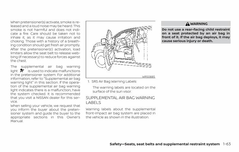
When pretensioner(s) activate, smoke is re-leased and a loud noise may be heard. Thissmoke is not harmful and does not indi-cate a fire. Care should be taken not toinhale it, as it may cause irritation andchoking. Those with a history of a breath-ing condition should get fresh air promptly.After the pretensioner(s’) activation, loadlimiters allow the seat belt to release web-bing (if necessary) to reduce forces againstthe chest.
The supplemental air bag warninglight is used to indicate malfunctionsin the pretensioner system. For additionalinformation, refer to "Supplemental air bagwarning light" in this section. If the opera-tion of the supplemental air bag warninglight indicates there is a malfunction, havethe system checked. It is recommendedthat you visit a NISSAN dealer for this ser-vice.When selling your vehicle, we request thatyou inform the buyer about the preten-sioner system and guide the buyer to theappropriate sections in this Owner’sManual.
1. SRS Air Bag Warning Labels
The warning labels are located on thesurface of the sun visor.
SUPPLEMENTAL AIR BAG WARNINGLABELSWarning labels about the supplementalfront-impact air bag system are placed inthe vehicle as shown in the illustration.
WARNINGDo not use a rear-facing child restrainton a seat protected by an air bag infront of it. If the air bag deploys, it maycause serious injury or death.
WRS0885
Safety—Seats, seat belts and supplemental restraint system 1-63

SUPPLEMENTAL AIR BAG WARNINGLIGHTThe supplemental air bag warning light,displaying in the instrument panel,monitors the circuits for the air bag sys-tems, pretensioner(s) and all related wiring.When the ignition switch is placed in the ONposition, the supplemental air bag warninglight illuminates for about 7 seconds andthen turns off. This means the system isoperational.
If any of the following conditions occur, thefront air bag, side air bag, curtain air bagand pretensioner systems need servicing:
∙ The supplemental air bag warning lightremains on after approximately 7 sec-onds.
∙ The supplemental air bag warning lightflashes intermittently.
∙ The supplemental air bag warning lightdoes not come on at all.
Under these conditions, the front air bag,side air bag, curtain air bag or pretensionersystems may not operate properly. Theymust be checked and repaired. It is recom-mended that you visit a NISSAN dealer forthis service.
WARNINGIf the supplemental air bag warninglight is on, it could mean that the frontair bag, side air bag, curtain air bagand/or pretensioner systems will notoperate in an accident. To help avoidinjury to yourself or others, have yourvehicle checked as soon as possible. It isrecommended that you visit a NISSANdealer for this service.
Repair and replacementprocedureThe front air bags, side air bags, curtain airbags and pretensioner(s) are designed toinflate on a one-time-only basis. As a re-minder, unless it is damaged, the supple-mental air bag warning light remains illu-minated after inflation has occurred. Thesesystems should be repaired and/or re-placed as soon as possible. It is recom-mended that you visit a NISSAN dealer forthis service.
When maintenance work is required on thevehicle, the front air bags, side air bags,curtain air bags, pretensioner(s) and re-lated parts should be pointed out to theperson performing the maintenance. Theignition switch should always be placed inthe LOCK position when working under thehood or inside the vehicle.
LRS0100
1-64 Safety—Seats, seat belts and supplemental restraint system
WARNING∙ Once a front air bag, side air bag, or
curtain air bag has inflated, the airbag module will not function againand must be replaced. Additionally,the activated pretensioner(s) mustalso be replaced. The air bag moduleand pretensioner(s) should be re-placed. It is recommended that youvisit a NISSAN dealer for this service.However, the air bag module and pre-tensioner(s) cannot be repaired.
∙ The front air bag, side air bag, curtainair bag systems and the pretensionersystem should be inspected if there isany damage to the front end or sideportion of the vehicle. It is recom-mended that you visit a NISSAN dealerfor this service.
∙ If you need to dispose of the supple-mental air bag or pretensioner sys-tems or scrap the vehicle, it is recom-mended that you contact a NISSANdealer for this service. Incorrect dis-posal procedures could cause per-sonal injury.
∙ If there is an impact to your vehiclefrom any direction, your OccupantClassification Sensor (OCS) should bechecked to verify it is still functioningcorrectly. It is recommended that youvisit a NISSAN dealer for this service.The OCS should be checked even if noair bags deploy as a result of the im-pact. Failure to verify proper OCSfunction may result in an improper airbag deployment resulting in injury ordeath.
Safety—Seats, seat belts and supplemental restraint system 1-65

2 Instruments and controls
Instrument panel . . . . . . . . . . . . . . . . . . . . . . . . . . . . . . . . 2-2Meters and gauges. . . . . . . . . . . . . . . . . . . . . . . . . . . . . . 2-4
Speedometer and odometer . . . . . . . . . . . . . . . . . 2-4Tachometer . . . . . . . . . . . . . . . . . . . . . . . . . . . . . . . . . . 2-6Fuel gauge . . . . . . . . . . . . . . . . . . . . . . . . . . . . . . . . . . . 2-6Assist charge gauge. . . . . . . . . . . . . . . . . . . . . . . . . . 2-7
Compass (if so equipped) . . . . . . . . . . . . . . . . . . . . . . . 2-7Compass display . . . . . . . . . . . . . . . . . . . . . . . . . . . . . 2-7
Warning lights, indicator lights and audiblereminders . . . . . . . . . . . . . . . . . . . . . . . . . . . . . . . . . . . . . . 2-10
Checking lights . . . . . . . . . . . . . . . . . . . . . . . . . . . . . . .2-11Warning lights . . . . . . . . . . . . . . . . . . . . . . . . . . . . . . . .2-11Indicator lights . . . . . . . . . . . . . . . . . . . . . . . . . . . . . . 2-17Audible reminders . . . . . . . . . . . . . . . . . . . . . . . . . . . 2-20
Vehicle information display . . . . . . . . . . . . . . . . . . . . . 2-21How to use the vehicle informationdisplay . . . . . . . . . . . . . . . . . . . . . . . . . . . . . . . . . . . . . . 2-21Startup display . . . . . . . . . . . . . . . . . . . . . . . . . . . . . . 2-21Resetting the drive computer. . . . . . . . . . . . . . . . 2-22Settings . . . . . . . . . . . . . . . . . . . . . . . . . . . . . . . . . . . . . 2-22Vehicle information display warningsand indicators . . . . . . . . . . . . . . . . . . . . . . . . . . . . . . . 2-33
Security systems . . . . . . . . . . . . . . . . . . . . . . . . . . . . . . . 2-40Vehicle security system . . . . . . . . . . . . . . . . . . . . . 2-40
NISSAN Vehicle Immobilizer System . . . . . . . . . 2-42Wiper and washer switch . . . . . . . . . . . . . . . . . . . . . . . 2-43
Switch operation . . . . . . . . . . . . . . . . . . . . . . . . . . . . 2-43Rear switch operation . . . . . . . . . . . . . . . . . . . . . . . 2-44
Rear window and outside mirror defrosterswitch . . . . . . . . . . . . . . . . . . . . . . . . . . . . . . . . . . . . . . . . . . 2-45Headlight and turn signal switch . . . . . . . . . . . . . . . 2-46
Headlight control switch. . . . . . . . . . . . . . . . . . . . . 2-46LED Daytime Running Lights (DRL)system . . . . . . . . . . . . . . . . . . . . . . . . . . . . . . . . . . . . . . 2-50Instrument brightness control. . . . . . . . . . . . . . . 2-51Turn signal switch . . . . . . . . . . . . . . . . . . . . . . . . . . . 2-51Fog light switch (if so equipped) . . . . . . . . . . . . . 2-52
Horn . . . . . . . . . . . . . . . . . . . . . . . . . . . . . . . . . . . . . . . . . . . 2-52Heated seat switches . . . . . . . . . . . . . . . . . . . . . . . . . . 2-53Heated steering wheel switch (if so equipped) . . 2-54Dynamic driver assistance switch(if so equipped) . . . . . . . . . . . . . . . . . . . . . . . . . . . . . . . . . 2-54Vehicle Dynamic Control (VDC) OFF switch. . . . . . 2-55All-Wheel Drive (AWD) LOCK switch(if so equipped) . . . . . . . . . . . . . . . . . . . . . . . . . . . . . . . . . 2-56Rear Door Alert . . . . . . . . . . . . . . . . . . . . . . . . . . . . . . . . . 2-56E-call (SOS) button (if so equipped) . . . . . . . . . . . . . 2-57Power outlets . . . . . . . . . . . . . . . . . . . . . . . . . . . . . . . . . . 2-57
12v outlets . . . . . . . . . . . . . . . . . . . . . . . . . . . . . . . . . . . 2-57Extended storage switch . . . . . . . . . . . . . . . . . . . . . . . 2-59Storage . . . . . . . . . . . . . . . . . . . . . . . . . . . . . . . . . . . . . . . . 2-60
Front-door pockets. . . . . . . . . . . . . . . . . . . . . . . . . . 2-60Seatback pockets . . . . . . . . . . . . . . . . . . . . . . . . . . . 2-60Glove box. . . . . . . . . . . . . . . . . . . . . . . . . . . . . . . . . . . . 2-61Console box . . . . . . . . . . . . . . . . . . . . . . . . . . . . . . . . . 2-61Overhead sunglasses storage . . . . . . . . . . . . . . . 2-62Cup holders . . . . . . . . . . . . . . . . . . . . . . . . . . . . . . . . . 2-62Cargo area storage bin . . . . . . . . . . . . . . . . . . . . . . 2-64Luggage hooks. . . . . . . . . . . . . . . . . . . . . . . . . . . . . . 2-64Cargo cover (if so equipped) . . . . . . . . . . . . . . . . . 2-65Roof rack (if so equipped) . . . . . . . . . . . . . . . . . . . . 2-66
Windows . . . . . . . . . . . . . . . . . . . . . . . . . . . . . . . . . . . . . . . 2-67Power windows . . . . . . . . . . . . . . . . . . . . . . . . . . . . . 2-67
Power moonroof (if so equipped) . . . . . . . . . . . . . . . 2-70Interior lights . . . . . . . . . . . . . . . . . . . . . . . . . . . . . . . . . . . 2-72
Console light . . . . . . . . . . . . . . . . . . . . . . . . . . . . . . . . 2-73Map lights . . . . . . . . . . . . . . . . . . . . . . . . . . . . . . . . . . . 2-73Personal lights (if so equipped) . . . . . . . . . . . . . . 2-73Room light (if so equipped) . . . . . . . . . . . . . . . . . . 2-74
Luggage compartment light . . . . . . . . . . . . . . . . . . . 2-74HomeLink® Universal Transceiver(if so equipped) . . . . . . . . . . . . . . . . . . . . . . . . . . . . . . . . . 2-75
Programming HomeLink® . . . . . . . . . . . . . . . . . . . 2-76Programming HomeLink® for Canadiancustomers and gate openers. . . . . . . . . . . . . . . . 2-77Operating the HomeLink® UniversalTransceiver . . . . . . . . . . . . . . . . . . . . . . . . . . . . . . . . . . 2-78Programming trouble-diagnosis . . . . . . . . . . . . 2-78Clearing the programmed information . . . . . . 2-78Reprogramming a single HomeLink®button. . . . . . . . . . . . . . . . . . . . . . . . . . . . . . . . . . . . . . . 2-78If your vehicle is stolen. . . . . . . . . . . . . . . . . . . . . . . 2-79

1. Vent (P. 4-29)2. Headlight/fog light (if so
equipped)/turn signal switch(P. 2-46)
3. Meters and gauges (P. 2-4)Warning and indicator lights(P. 2-10)Vehicle information display (P. 2-21)
4. Wiper and washer switch (P. 2-43)Rear wiper washer switch (P. 2-43)
5. Push-button ignition switch(P. 5-14)
6. Hazard warning flasher switch(P. 6-2)
7. Radio*Navigation system*(if so equipped)
8. Front passenger supplemental airbag (P. 1-45)
9. Glove box (P. 2-60)10. Heater and air conditioning
controls (P. 4-30)11. Power outlet (P. 2-57)12. Shift lever (P. 5-19)13. Auxiliary jack*
USB port*14. Front passenger air bag status
light (P. 1-45)LII2516
INSTRUMENT PANEL
2-2 Instruments and controls

15. Cruise control switches(if so equipped) (P. 5-55)Intelligent Cruise Control (ICC)switches (if so equipped) (P. 5-57)Bluetooth® Hands-Free PhoneSystem*
16. Driver supplemental air bag(P. 1-45)Horn (P. 2-52)
17. Tilt and telescopic steering (P. 3-34)18. Control panel and vehicle informa-
tion display switches (P. 2-21)19. Hood release (P. 3-23)20. SPORT mode switch (P. 5-25)
Fuel door release (P. 3-31)ECO mode switch (P. 5-25)Liftgate instrument panel switch(if so equipped) (P. 3-24)All-Wheel Drive (AWD) LOCK switch(if so equipped) (P. 2-56)Vehicle Dynamic Control (VDC) OFFswitch (P. 2-55)Heated steering wheel switch(if so equipped) (P. 2-54)Dynamic driver assistance switch(if so equipped) (P. 2-54)
21. Instrument brightness control(P. 2-51)Twin trip odometer reset switch(P. 2-5)
*: Refer to the separate NissanConnect®Owner’s Manual.
Refer to the page number indicated inparentheses for operating details.
Instruments and controls 2-3

1. Tachometer2. Warning and indicator lights3. Vehicle information display4. Speedometer5. Fuel gauge6. Assist charge gauge
SPEEDOMETER AND ODOMETERThis vehicle is equipped with a speedom-eter and odometer. The speedometer islocated on the right side of the meter clus-ter. The odometer is located within the ve-hicle information display.
SpeedometerThe speedometer indicates vehicle speed.
LIC3636
LIC2255
METERS AND GAUGES
2-4 Instruments and controls

Odometer/Twin trip odometerThe odometer and the twin trip odometer�1 are displayed in the vehicle informationdisplay when the ignition switch is placedin the ON position.
The odometer records the total distancethe vehicle has been driven.
The twin trip odometer records the dis-tance of individual trips.
Changing the display
Push the TRIP RESET switch �2 on the leftside of the instrument panel to change thedisplay as follows:
ODO → Trip → Trip → ODO
Resetting the trip odometerPush the TRIP RESET switch �2 until thedesired trip odometer (Trip orTrip ) is displayed.Push and hold the TRIP RESET switch �2 formore than 1 second to reset the currentlydisplayed trip odometer to zero.
Clock and outside temperaturedisplayClock
The clock is displayed at the top of thevehicle information display.
Outside temperature display
The outside temperature is displayed atthe top of the vehicle information display.The snowflake icon appears if the outsidetemperature is below 37°F (3°C). The tem-perature can be changed to display in Cel-sius or Fahrenheit. For additional informa-tion, refer to “Unit” in this section.
LIC3693 LIC3694
Instruments and controls 2-5

TACHOMETERThe tachometer indicates engine speed inrevolutions per minute (rpm). Do not revengine into the red zone �1 .
CAUTIONWhen engine speed approaches the redzone, reduce engine speed. Operatingthe engine in the red zone may causeserious engine damage.
FUEL GAUGEThe gauge indicates the approximate fuellevel in the tank.
The gauge may move slightly during brak-ing, turning, acceleration, or going up ordown hills.
The gauge needle returns to 0 (Empty) af-ter the ignition switch is placed in the OFFposition.
The low fuel warning message appears inthe vehicle information display when theamount of fuel in the tank is getting low.
Refill the fuel tank before the gauge reg-isters 0 (Empty).The indicates that the fuel-filler dooris located on the passenger’s side of thevehicle.
CAUTION
∙ If the vehicle runs out of fuel, theMalfunction Indicator Light (MIL) maycome on. Refuel as soon as possible.After a few driving trips. the lightshould turn off. If the light remains onafter a few driving trips, have the ve-hicle inspected. It is recommendedthat you visit a NISSAN dealer for thisservice.
∙ For additional information, refer to“Malfunction Indicator Light (MIL)” inthis section.
LIC2219 LIC2222
2-6 Instruments and controls
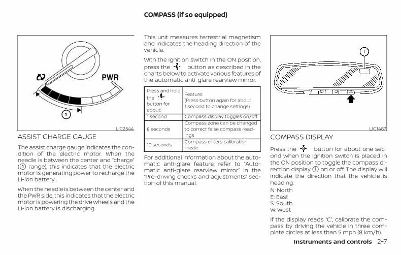
ASSIST CHARGE GAUGEThe assist charge gauge indicates the con-dition of the electric motor. When theneedle is between the center and “charge”(�1 range), this indicates that the electricmotor is generating power to recharge theLi-ion battery.
When the needle is between the center andthe PWR side, this indicates that the electricmotor is powering the drive wheels and theLi-ion battery is discharging.
This unit measures terrestrial magnetismand indicates the heading direction of thevehicle.
With the ignition switch in the ON position,press the button as described in thecharts below to activate various features ofthe automatic anti-glare rearview mirror.
Press and holdthebutton forabout:
Feature:(Press button again for about1 second to change settings)
1 second Compass display toggles on/off
8 secondsCompass zone can be changedto correct false compass read-ings
10 seconds Compass enters calibrationmode
For additional information about the auto-matic anti-glare feature, refer to “Auto-matic anti-glare rearview mirror” in the“Pre-driving checks and adjustments” sec-tion of this manual.
COMPASS DISPLAY
Press the button for about one sec-ond when the ignition switch is placed inthe ON position to toggle the compass di-rection display �1 on or off. The display willindicate the direction that the vehicle isheading.N: NorthE: EastS: SouthW: West
If the display reads “C”, calibrate the com-pass by driving the vehicle in three com-plete circles at less than 5 mph (8 km/h).
LIC2544 LIC1487
COMPASS (if so equipped)
Instruments and controls 2-7

You can also calibrate the compass by driv-ing your vehicle on your everyday route.The compass will be calibrated once it hastracked three complete circles.
WIC0355
2-8 Instruments and controls

Zone variation change procedureThe difference between magnetic northand geographical north is known as vari-ance. In some areas, this difference cansometimes be great enough to cause falsecompass readings. Follow these instruc-tions to set the variance for your particularlocation if this happens:
1. Press and hold the button forabout 8 seconds. The current zonenumber will appear in the display. Re-lease the button.
2. Find your current location on the zonemap. Refer to the illustration.
3. Press the button repeatedly totoggle through the zone numbers untilthe desired number appears in the dis-play. Once you have selected a zonenumber, the display will show a com-pass direction within a few seconds.
Inaccurate compass directionThe compass display is equipped with au-tomatic correction function. If the correctdirection is not shown, follow this proce-dure.
1. With the display turned on, press andhold the for about 10 seconds.The “C” icon in the compass display willilluminate.
2. Calibrate the compass by driving thevehicle in three complete circles at amaximum speed of 5 mph (8 km/h).
3. After completing the circles, the displayshould return to normal.
CAUTION∙ Do not install a ski rack, antenna, etc.,
which are attached to the vehicle bymeans of a magnet. They affect theoperation of the compass.
∙ When cleaning the mirror, use a papertowel or similar material dampenedwith glass cleaner. Do not spray glasscleaner directly on the mirror as itmay cause the liquid cleaner to enterthe mirror housing.
Instruments and controls 2-9
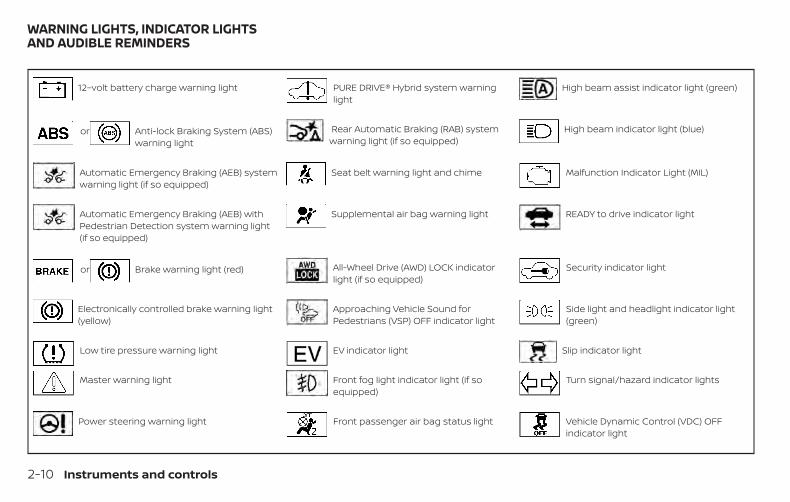
12–volt battery charge warning light PURE DRIVE® Hybrid system warninglight
High beam assist indicator light (green)
or Anti-lock Braking System (ABS)warning light
Rear Automatic Braking (RAB) systemwarning light (if so equipped)
High beam indicator light (blue)
Automatic Emergency Braking (AEB) systemwarning light (if so equipped)
Seat belt warning light and chime Malfunction Indicator Light (MIL)
Automatic Emergency Braking (AEB) withPedestrian Detection system warning light(if so equipped)
Supplemental air bag warning light READY to drive indicator light
or Brake warning light (red) All-Wheel Drive (AWD) LOCK indicatorlight (if so equipped)
Security indicator light
Electronically controlled brake warning light(yellow)
Approaching Vehicle Sound forPedestrians (VSP) OFF indicator light
Side light and headlight indicator light(green)
Low tire pressure warning light EV indicator light Slip indicator light
Master warning light Front fog light indicator light (if soequipped)
Turn signal/hazard indicator lights
Power steering warning light Front passenger air bag status light Vehicle Dynamic Control (VDC) OFFindicator light
WARNING LIGHTS, INDICATOR LIGHTSAND AUDIBLE REMINDERS
2-10 Instruments and controls

CHECKING LIGHTSWith all doors closed, apply the parkingbrake, fasten the seat belts and place theignition switch in the ON position withoutstarting the hybrid system. The followinglights (if so equipped) will come on:
, , , , ,
The following lights (if so equipped) comeon briefly and then go off:
, , , , , ,
If any light fails to come on or operate in away other than described, it may indicate aburned-out bulb and/or a system mal-function. Have the system checked. It isrecommended that you visit a NISSANdealer for this service.
Some indicators and warnings are also dis-played on the vehicle information displaybetween the speedometer and tachom-eter. For additional information, refer to “Ve-hicle information display” in this section.
WARNING LIGHTSFor additional information, refer to “Vehicleinformation display” in this section.
12–volt battery chargewarning light
If this light comes on when the READY todrive indicator light comes on, it may indi-cate the charging system is not function-ing properly. Have your vehicle serviced im-mediately. It is recommended that you visita NISSAN dealer for this service.
CAUTIONThe charging system may not be func-tioning properly if the 12–volt batterycharge warning light comes on whilethe hybrid system is running. The hy-brid system will stop operating whenthe 12–volt battery becomes dis-charged. Immediately stop the vehiclein a safe place and contact a NISSANdealer.
or Anti-lock BrakingSystem (ABS)warning light
When the ignition switch is placed in the ONposition, the ABS warning light illuminatesand then turns off. This indicates the ABS isoperational.
If the ABS warning light illuminates whilethe hybrid system is running, or while driv-ing, it may indicate the ABS is not function-ing properly. Have the system checked. It isrecommended that you visit a NISSANdealer for this service.
If an ABS malfunction occurs, the anti-lockfunction is turned off. The brake systemthen operates normally, but without anti-lock assistance. For additional information,refer to “Brake system” in the “Starting anddriving” section of this manual.
Automatic EmergencyBraking (AEB) systemwarning light (if soequipped)
This light comes on when the ignitionswitch is placed in the ON position. It turnsoff after the engine is started.
Instruments and controls 2-11
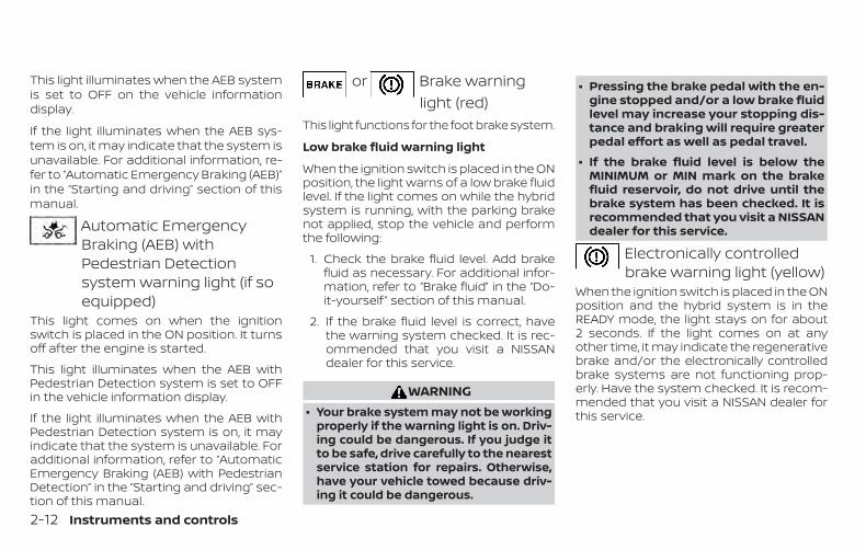
This light illuminates when the AEB systemis set to OFF on the vehicle informationdisplay.
If the light illuminates when the AEB sys-tem is on, it may indicate that the system isunavailable. For additional information, re-fer to “Automatic Emergency Braking (AEB)”in the “Starting and driving” section of thismanual.
Automatic EmergencyBraking (AEB) withPedestrian Detectionsystem warning light (if soequipped)
This light comes on when the ignitionswitch is placed in the ON position. It turnsoff after the engine is started.
This light illuminates when the AEB withPedestrian Detection system is set to OFFin the vehicle information display.
If the light illuminates when the AEB withPedestrian Detection system is on, it mayindicate that the system is unavailable. Foradditional information, refer to “AutomaticEmergency Braking (AEB) with PedestrianDetection” in the “Starting and driving” sec-tion of this manual.
or Brake warninglight (red)
This light functions for the foot brake system.
Low brake fluid warning light
When the ignition switch is placed in the ONposition, the light warns of a low brake fluidlevel. If the light comes on while the hybridsystem is running, with the parking brakenot applied, stop the vehicle and performthe following:
1. Check the brake fluid level. Add brakefluid as necessary. For additional infor-mation, refer to “Brake fluid” in the “Do-it-yourself ” section of this manual.
2. If the brake fluid level is correct, havethe warning system checked. It is rec-ommended that you visit a NISSANdealer for this service.
WARNING∙ Your brake system may not be working
properly if the warning light is on. Driv-ing could be dangerous. If you judge itto be safe, drive carefully to the nearestservice station for repairs. Otherwise,have your vehicle towed because driv-ing it could be dangerous.
∙ Pressing the brake pedal with the en-gine stopped and/or a low brake fluidlevel may increase your stopping dis-tance and braking will require greaterpedal effort as well as pedal travel.
∙ If the brake fluid level is below theMINIMUM or MIN mark on the brakefluid reservoir, do not drive until thebrake system has been checked. It isrecommended that you visit a NISSANdealer for this service.
Electronically controlledbrake warning light (yellow)
When the ignition switch is placed in the ONposition and the hybrid system is in theREADY mode, the light stays on for about2 seconds. If the light comes on at anyother time, it may indicate the regenerativebrake and/or the electronically controlledbrake systems are not functioning prop-erly. Have the system checked. It is recom-mended that you visit a NISSAN dealer forthis service.
2-12 Instruments and controls

If the hydraulic brake warning light alsocomes on with the parking brake not ap-plied, stop the vehicle immediately and it isrecommended that you call a NISSANdealer. For additional information, refer to"Brake system" in the "Starting and driving"section of this manual.
WARNINGYour brake system may not be workingproperly if both the brake warning lightand electronically controlled brake sys-tem warning light come on when thehybrid system is in READY mode and theparking brake is not applied. Drivingcould be dangerous. If you judge it to besafe, drive carefully to the nearest ser-vice station for repairs. Otherwise, haveyour vehicle towed because drivingcould be dangerous.
Low tire pressure warninglight
Your vehicle is equipped with a Tire Pres-sure Monitoring System (TPMS) that moni-tors the tire pressure of all tires except thespare.
The low tire pressure warning light warnsof low tire pressure or indicates that theTPMS is not functioning properly.
After the ignition switch is placed in the ONposition, this light illuminates for about1 second and turns off.
Low tire pressure warning
If the vehicle is being driven with low tirepressure, the warning light will illumi-nate. A “Tire Pressure Low - Add Air”warning also appears in the vehicle in-formation display.
When the low tire pressure warning lightilluminates, you should stop and adjustthe tire pressure of all four tires to therecommended COLD tire pressure shownon the Tire and Loading Information la-bel located in the driver’s door opening.The low tire pressure warning light doesnot automatically turn off when the tirepressure is adjusted. After the tire is in-flated to the recommended pressure,the vehicle must be driven at speedsabove 16 mph (25 km/h) to activate theTPMS and turn off the low tire pressurewarning light. Use a tire pressure gaugeto check the tire pressure.
The “Tire Pressure Low - Add Air” warningappears each time the ignition switch isplaced in the ON position as long as the lowtire pressure warning light remains illumi-nated.
For additional information, refer to “Vehicleinformation display” in this section and“Tire Pressure Monitoring System (TPMS)” inthe “Starting and driving” section and in the“In case of emergency” section of thismanual.
TPMS malfunction
If the TPMS is not functioning properly, thelow tire pressure warning light will flash forapproximately 1 minute when the ignitionswitch is placed in the ON position. Thelight will remain on after 1 minute. Have thesystem checked. It is recommended thatyou visit a NISSAN dealer for this service.The "Tire Pressure Low — Add Air" warningdoes not appear if the low tire pressurewarning light illuminates to indicate aTPMS malfunction.
For additional information, refer to “TirePressure Monitoring System (TPMS)” in the“Starting and driving” section and “Tirepressure” in the “Do-it-yourself ” section ofthis manual.
Instruments and controls 2-13

WARNING∙ Radio waves could adversely affect
electric medical equipment. Thosewho use a pacemaker should contactthe electric medical equipmentmanufacturer for the possible influ-ences before use.
∙ If the light does not illuminate withthe ignition switch placed in the ONposition, have the vehicle checked assoon as possible. It is recommendedthat you visit a NISSAN dealer for thisservice.
∙ If the light illuminates while driving,avoid sudden steering maneuvers orabrupt braking, reduce vehicle speed,pull off the road to a safe location andstop the vehicle as soon as possible.Driving with under-inflated tires maypermanently damage the tires and in-crease the likelihood of tire failure. Se-rious vehicle damage could occur andmay lead to an accident and could re-sult in serious personal injury ordeath. Check the tire pressure for allfour tires. Adjust the tire pressure tothe recommended COLD tire pressureshown on the Tire and Loading Infor-mation label located in the driver’sdoor opening to turn the low tire pres-sure warning light off. If the light stillilluminates while driving after adjust-ing the tire pressure, a tire may be flator the TPMS may be malfunctioning. Ifyou have a flat tire, replace it with aspare tire as soon as possible. If no tireis flat and all tires are properly in-flated, have the vehicle checked. It isrecommended that you visit a NISSANdealer for this service.
∙ When replacing a wheel without theTPMS such as the spare tire, the TPMSwill not function and the low tire pres-sure warning light will flash for ap-proximately 1 minute. The light will re-main on after 1 minute. Have yourtires replaced and/or TPMS systemreset as soon as possible. It is recom-mended that you visit a NISSAN dealerfor these services.
∙ Replacing tires with those not origi-nally specified by NISSAN could affectthe proper operation of the TPMS.
CAUTION∙ The TPMS is not a substitute for the
regular tire pressure check. Be sure tocheck the tire pressure regularly.
∙ If the vehicle is being driven at speedsof less than 16 mph (25 km/h), theTPMS may not operate correctly.
∙ Be sure to install the specified size oftires to the four wheels correctly.
2-14 Instruments and controls

Master warning light
When the ignition is in the ON position, themaster warning light illuminates if any ofthe following are displayed on the vehicleinformation display.
∙ All-Wheel Drive (AWD) Tire Size IncorrectSee Owner’s Manual
∙ All-Wheel Drive (AWD) High Temp. Stopvehicle
∙ All-Wheel Drive (AWD) Error See Owner’sManual
∙ No key warning
∙ Low fuel warning
∙ Low windshield-washer fluid warning
∙ Parking brake release warning
∙ Door/liftgate open warning
∙ Loose fuel cap warning
If the All-Wheel Drive (AWD) system mal-functions, or the diameter of the front andthe rear wheels are different, the masterwarning light will illuminate. For additionalinformation, refer to “All-Wheel Drive (AWD)”in the “Starting and driving” section of thismanual.
∙ If the warning light comes on while driv-ing there may be a malfunction in theAWD system. Reduce the vehicle speedand have your vehicle checked as soonas possible. It is recommended that youvisit a NISSAN dealer for this service.
CAUTION∙ If the master warning light was illumi-
nated while driving:
—AWD High Temp Stop vehicle
Pull off the road in a safe area and idlethe engine. The driving mode willchange to 2WD to prevent the AWD sys-tem from malfunctioning. If the warn-ing light turns off, you can drive again.
—Tire Size Incorrect See Owner’sManual
Pull off the road in a safe area and idlethe engine. Check that all tire sizes arethe same, tire pressure is correct andtires are not worn.
∙ If the warning light is still on after theabove operations, have your vehiclechecked as soon as possible. It is rec-ommended that you visit a NISSANdealer for this service.
Power steering warninglight
WARNING∙ If the hybrid system is not running or
is turned off while driving, the powerassist for the steering will not work.Steering will be harder to operate.
∙ When the power steering warninglight illuminates with the hybrid sys-tem running, there will be no powerassist for the steering. You will stillhave control of the vehicle, but thesteering will be harder to operate.Have the power steering systemchecked. It is recommended that youvisit a NISSAN dealer for this service.
When the ignition switch is placed in the ONposition, the power steering warning lightilluminates. After starting the hybrid sys-tem, the power steering warning light turnsoff. This indicates the power steering is op-erational.
Instruments and controls 2-15

If the power steering warning light illumi-nates while the hybrid system is running, itmay indicate the power steering is notfunctioning properly and may need servic-ing. Have the power steering checked. It isrecommended that you visit a NISSANdealer for this service.
When the power steering warning light illu-minates with the hybrid system running,there will be no power assist for the steer-ing, but you will still have control of thevehicle. At this time, greater steering effortis required to operate the steering wheel,especially in sharp turns and at low speeds.
For additional information, refer to “Powersteering” in the “Starting and driving” sec-tion of this manual.
PURE DRIVE® HybridSystem warning light
When the ignition switch is in the ON posi-tion, the hybrid system warning light illumi-nates. After starting the hybrid system, thehybrid system warning light turns off. If thehybrid system warning light illuminateswhile driving, it may indicate that there is amalfunction in the electric motor and/orother hybrid system components. Stop
your vehicle immediately and it is recom-mended that you visit a NISSAN dealer forservice.
Rear Automatic Braking(RAB) system warning light(if so equipped)
This light comes on when the ignitionswitch is placed in the ON position. It turnsoff after the hybrid system is started.
This light illuminates when the RAB systemis turned off in the vehicle information dis-play.
If the light illuminates when the RAB sys-tem is on, it may indicate that the system isunavailable. For additional information, re-fer to “Rear Automatic Braking (RAB)” in the“Starting and driving” section of thismanual.
Seat belt warning light andchime
The light and chime remind you to fastenyour seat belts. The light illuminates when-ever the ignition switch is placed in the ONor START position and remains illuminateduntil the driver’s seat belt is fastened. At the
same time, the chime sounds for about6 seconds unless the driver’s seat belt issecurely fastened.
The seat belt warning light may also illumi-nate if the front passenger’s seat belt is notfastened when the front passenger’s seatis occupied. For 7 seconds after the ignitionswitch is placed in the ON position, the sys-tem does not activate the warning light forthe front passenger.
For additional information, refer to “Seatbelts” in the “Safety—Seats, seat belts andsupplemental restraint system” section ofthis manual.
Supplemental air bagwarning light
When the ignition switch is placed in the ONor START position, the supplemental airbag warning light illuminates for about7 seconds and then turns off. This meansthe system is operational.
If any of the following conditions occur, thefront air bag, side air bag, curtain air bag,and pretensioner seat belt systems needservicing:
∙ The supplemental air bag warning lightremains on after approximately 7 sec-onds.
2-16 Instruments and controls

∙ The supplemental air bag warning lightflashes intermittently.
∙ The supplemental air bag warning lightdoes not come on at all.
It is recommended that you visit a NISSANdealer for these services.
Unless checked and repaired, the supple-mental restraint system (air bag system)and/or the pretensioner(s) may not func-tion properly. For additional information, re-fer to “Supplemental Restraint System(SRS)” in the “Safety—Seats, seat belts andsupplemental restraint system” section ofthis manual.
WARNINGIf the supplemental air bag warninglight is on, it could mean that the frontair bag, side air bag, curtain air bagand/or pretensioner systems will notoperate in an accident. To help avoidinjury to yourself or others, have yourvehicle checked as soon as possible. It isrecommended that you visit a NISSANdealer for this service.
INDICATOR LIGHTSFor additional information, refer to “Vehicleinformation display” in this section.
All-Wheel Drive (AWD) LOCKindicator light (if soequipped)
When the ignition switch is in the ON posi-tion, the All-Wheel Drive (AWD) LOCK indica-tor light illuminates and then turns off.
When selecting AWD LOCK mode while thehybrid system is running, the AWD LOCKindicator light illuminates.
CAUTIONDo not drive on dry hard surface roadsin the LOCK mode.
Approaching VehicleSound for Pedestrians(VSP) OFF indicator light
This light comes on if there is a malfunctionin the Approaching Vehicle Sound for Pe-destrians (VSP) system.
EV indicator light
This light illuminates when the enginestops running.
Front fog light indicatorlight (if so equipped)
The front fog light indicator light illumi-nates when the front fog lights are on. Foradditional information, refer to “Fog lightswitch” in this section.
Front passenger air bagstatus light
The front passenger air bag status light willbe lit and the passenger front air bag will beoff depending on how the front passengerseat is being used.
For additional information, refer to “Frontpassenger air bag and status light” in the“Safety — Seats, seat belts and supplemen-tal restraint system” section of this manual.
Instruments and controls 2-17

High beam assist indicatorlight (green)
This indicator light illuminates when theheadlights come on while the headlightswitch is in the AUTO position with the highbeams selected. This indicates that thehigh beam assist is operational.
For additional information, refer to “Head-light and turn signal switch” in this section.
High beam indicator light(blue)
This blue light comes on when the head-light high beams are on and goes out whenthe low beams are selected.
The high beam indicator light also comeson when the passing signal is activated.
Malfunction Indicator Light(MIL)
If this indicator light comes on steady orblinks while the hybrid system is running, itmay indicate a potential emission controlmalfunction.
The MIL may also come on steady if thefuel-filler cap is loose or missing, or if thevehicle runs out of fuel. Check to make surethe fuel-filler cap is installed and closedtightly, and that the vehicle has at least3 gallons (11.4 liters) of fuel in the fuel tank.
After a few driving trips, the lightshould turn off if no other potential emis-sion control system malfunction exists.If this indicator light comes on steady for20 seconds and then blinks for 10 secondswhen the hybrid system is not running, itindicates that the vehicle is not ready for anemission control systeminspection/maintenance test. For addi-tional information, refer to “Readiness forinspection/maintenance (I/M) test” in the“Technical and consumer information” sec-tion of this manual.
Operation
The MIL will come on in one of two ways:
∙ MIL on steady — An emission control sys-tem malfunction has been detected.Check the fuel-filler cap if the Loose FuelCap warning appears in the vehicle infor-mation display. If the fuel-filler cap isloose or missing, tighten or install the capand continue to drive the vehicle.The light should turn off after a fewdriving trips. If the light does notturn off after a few driving trips, have thevehicle inspected. It is recommendedthat you visit a NISSAN dealer for this ser-vice. You do not need to have your vehicletowed to the dealer.
∙ MIL blinking — An engine misfire has beendetected which may damage the emis-sion control system. To reduce or avoidemission control system damage:
– do not drive at speeds above45 mph (72 km/h).
– avoid hard acceleration or decelera-tion.
– avoid steep uphill grades.
– if possible, reduce the amount ofcargo being hauled or towed.
2-18 Instruments and controls

The MIL may stop blinking and come onsteady. Have the vehicle inspected. It is rec-ommended that you visit a NISSAN dealerfor this service. You do not need to haveyour vehicle towed to the dealer.
CAUTIONContinued vehicle operation withouthaving the emission control systemchecked and repaired as necessarycould lead to poor driveability, reducedfuel economy, and possible damage tothe emission control system.
READY to drive indicatorlight
The READY to drive indicator light illumi-nates when the hybrid system is poweredand the vehicle may be driven.
Security indicator light
This light blinks when the ignition switch isplaced in the OFF or LOCK position.
The blinking security indicator light indi-cates that the security systems equippedon the vehicle are operational.
For additional information, refer to “Securitysystems” in this section.
Side light and headlightindicator light (green)
The side light and headlight indicator lightilluminates when the side light or headlightposition is selected. For additional informa-tion, refer to “Headlight and turn signalswitch” in this section.
Slip indicator light
This indicator will blink when the VDC sys-tem is operating, thus alerting the driver tothe fact that the road surface is slipperyand the vehicle is nearing its traction limits.
You may feel or hear the system working;this is normal.
The light will blink for a few seconds afterthe VDC system stops limiting wheel spin.
The indicator light also comes onwhen you place the ignition switch in theON position. The light will turn off after ap-proximately 2 seconds if the system is op-erational. If the light does not come onhave the system checked. It is recom-mended that you visit a NISSAN dealer forthis service.
Turn signal/hazardindicator lights
The appropriate light flashes when the turnsignal switch is activated.
Both lights flash when the hazard switch isturned on.
Vehicle Dynamic Control(VDC) OFF indicator light
This indicator light comes on when theVDC OFF switch is pushed to off. This indi-cates the VDC system has been turned off.
Push the VDC OFF switch again or restartthe hybrid system and the system will op-erate normally. For additional information,refer to “Vehicle Dynamic Control (VDC) sys-tem” in the “Starting and driving” section ofthis manual.
The VDC OFF indicator light also comes onwhen you place the ignition switch in theON position. The light will turn off afterabout 2 seconds if the system is opera-tional. If the light stays on or comes onalong with the indicator light whileyou are driving, have the VDC systemchecked. It is recommended that you visit aNISSAN dealer for this service.
Instruments and controls 2-19

While the VDC system is operating, youmight feel a slight vibration or hear the sys-tem working when starting the vehicle oraccelerating, but this is normal.
AUDIBLE REMINDERSBrake pad wear warningThe disc brake pads have audible wearwarnings. When a disc brake pad requiresreplacement, it makes a high pitchedscraping sound when the vehicle is in mo-tion, whether or not the brake pedal is de-pressed. Have the brakes checked as soonas possible if the warning sound is heard.
Key reminder chimeA chime sounds if the driver’s door isopened while the ignition switch is placedin the OFF position or placed in the OFF orLOCK position with the key left in the ve-hicle. Make sure the ignition switch isplaced in the LOCK position, and take thekey with you when leaving the vehicle.
Lane Departure Warning (LDW)and Intelligent Lane Intervention(I-LI) warning chime (if soequipped)When the LDW or I-LI system is on, thechime sounds if the vehicle is travelingclose to either the left or the right of atraveling lane with detectable lane mark-ers.
For additional information, refer to “LaneDeparture Warning (LDW)” or “IntelligentLane Intervention (I-LI)” in the “Starting anddriving” section of this manual.
Light reminder chimeWith the ignition switch placed in the OFFposition, a chime sounds when the driver’sdoor is opened if the headlights or parkinglights are on.
Turn the headlight control switch off beforeleaving the vehicle.
NISSAN Intelligent Key® doorbuzzerThe Intelligent Key door buzzer sounds ifany one of the following improper opera-tions is found.
∙ The Intelligent Key is left inside the ve-hicle when locking the doors.
∙ Any doors are not closed securely whenlocking the doors.
When the buzzer sounds, be sure to checkboth the vehicle and the Intelligent Key. Foradditional information, refer to “NISSAN In-telligent Key®” in the “Pre-driving checksand adjustments” section of this manual.
2-20 Instruments and controls
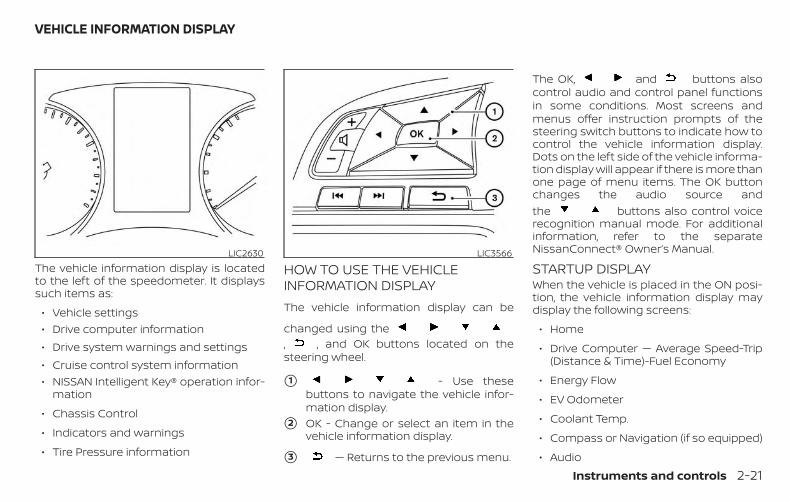
The vehicle information display is locatedto the left of the speedometer. It displayssuch items as:
∙ Vehicle settings∙ Drive computer information∙ Drive system warnings and settings∙ Cruise control system information∙ NISSAN Intelligent Key® operation infor-
mation
∙ Chassis Control
∙ Indicators and warnings
∙ Tire Pressure information
HOW TO USE THE VEHICLEINFORMATION DISPLAYThe vehicle information display can be
changed using the, , and OK buttons located on thesteering wheel.
�1 - Use thesebuttons to navigate the vehicle infor-mation display.
�2 OK - Change or select an item in thevehicle information display.
�3 — Returns to the previous menu.
The OK, and buttons alsocontrol audio and control panel functionsin some conditions. Most screens andmenus offer instruction prompts of thesteering switch buttons to indicate how tocontrol the vehicle information display.Dots on the left side of the vehicle informa-tion display will appear if there is more thanone page of menu items. The OK buttonchanges the audio source andthe buttons also control voicerecognition manual mode. For additionalinformation, refer to the separateNissanConnect® Owner’s Manual.
STARTUP DISPLAYWhen the vehicle is placed in the ON posi-tion, the vehicle information display maydisplay the following screens:
∙ Home
∙ Drive Computer — Average Speed-Trip(Distance & Time)-Fuel Economy
∙ Energy Flow
∙ EV Odometer
∙ Coolant Temp.
∙ Compass or Navigation (if so equipped)
∙ Audio
LIC2630 LIC3566
VEHICLE INFORMATION DISPLAY
Instruments and controls 2-21

∙ Intelligent Cruise (if so equipped)
∙ Driving Aids
∙ Tire Pressures
∙ 4x4–i
∙ Chassis Control
∙ Warnings
∙ Settings
Warnings will only display if there are anypresent. For additional information, refer to“Vehicle information display warnings andindicators” in this section.
To control which items display in the ve-hicle information display, refer to “Metersettings” in this section.
RESETTING THE DRIVE COMPUTER
1. Press the or buttons untilyou reach the desired drive computermode.
NOTE:
Once you have a drive computer dis-played, you can use the andbuttons to switch between Drive Com-puter �1 or �2 .
2. Press the OK button.
3. Select one of the following items:
∙ “Cancel” — returns to the previousscreen without resetting the trip com-puter.
∙ Drive computer value
– “Average Speed” - resets the averagespeed of the selected drive com-puter.
– “Distance” - resets the distance andtime of the selected drive computer.
– “Fuel Economy” - resets the fueleconomy of the selected drive com-puter.
∙ “All” — resets all linked values for the se-lected drive computer. This includesdistance and time, average fueleconomy and average speed informa-tion for the selected drive computer.
NOTE:
Drive computer 2 will automatically reseteach time the ignition is placed in theOFF position.
SETTINGSThe setting mode allows you to change theinformation displayed in the vehicle infor-mation display:
∙ Driver Assistance
∙ Clock
∙ Meter Settings
∙ Vehicle Settings
∙ Maintenance
∙ Alarm
∙ Tire Pressures
∙ Unit
∙ Language
∙ Factory Reset
2-22 Instruments and controls

Driver AssistanceThe driver assistance menu allows the userto change the settings for driving, parking,and braking aids.
Menu item ResultDriving Aids (if so equipped) Displays available driving aids.
Emergency Brake Allows user to turn the emergency brake feature on or off. For additional information, refer to “Automatic Emer-gency Braking (AEB)” and “Automatic Emergency Braking (AEB) with Pedestrian Detection” in the “Starting anddriving” section of this manual.
Front Allows user to turn the front emergency braking system on or off. For additional information, refer to “AutomaticEmergency Braking (AEB)”and “Automatic Emergency Braking (AEB) with Pedestrian Detection” in the “Starting anddriving section of your owner’s manual.
Rear Allows user to turn the rear emergency braking system on or off. For additional information, refer to “Rear Auto-matic Braking (RAB)” in the “Starting and driving section of your owner’s manual.
Lane Displays available lane options.Warning (LDW) Allows user to turn on the Lane Departure Warning (LDW) systems on or off. For additional information, refer to
“Lane Departure Warning (LDW)” in the “Starting and driving” section of this manual.Prevention (LDP) (ifso equipped)
Allows user to turn the Intelligent Lane Intervention (I-LI) system on or off. For additional information, refer to “Intel-ligent Lane Intervention (I-LI)” in the “Starting and driving” section of this manual.
Blind Spot Displays available blind spot options.Warning (BSW) Allows user to turn Blind Spot Warning (BSW) on or off. For additional information, refer to “Blind Spot Warning
(BSW)” or in the “Starting and driving” section of this manual.Parking Aids (if so equipped) Displays available parking aids.
Instruments and controls 2-23

Menu item ResultMoving Object Allows user to turn the Moving Object Detection (MOD) feature on or off. For additional information, refer to “Intelli-
gent Around View Monitor” in the “Monitor, climate, audio, phone and voice recognition systems” section of thismanual.
Cross Traffic Allows user to turn the Rear Cross Traffic Alert (RCTA) feature on or off.Front Sensor (if so equipped) Allows user to turn the front sensor on or off.Rear Sensor (if so equipped) Allows user to turn the rear sensor feature on or off.Display (if so equipped) Allows user to turn the display on or off.Volume (if so equipped) Allows user to select volume (High, Med. or Low).Range (if so equipped) Allows user to set the sensor range (Far, Mid. or Near).
Chassis Control Displays available chassis controls options.Trace Control Allows user to turn the trace control feature on or off. For additional information, refer to “Intelligent Trace Control
(I-TC)” in the “Starting and driving” section of this manual.Engine Brake Allows user to turn the engine brake feature on or off. For additional information, refer to “Intelligent Engine Brake
(I-EB)” in the “Starting and driving” section of this manual.
Clock
Menu item ResultClock Allows user to adjust the clock settings and time within the vehicle information display. Adjustments that
can be made include automatically setting the time, 12H/24H format, Daylight Savings Time, time zone, andmanually setting the time.The clock may also be set within the center display. For additional information, refer to the separateNissanConnect® Owner’s Manual.
2-24 Instruments and controls
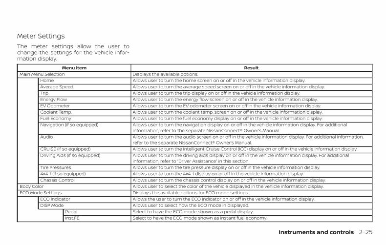
Meter SettingsThe meter settings allow the user tochange the settings for the vehicle infor-mation display.
Menu item ResultMain Menu Selection Displays the available options.
Home Allows user to turn the home screen on or off in the vehicle information display.Average Speed Allows user to turn the average speed screen on or off in the vehicle information display.Trip Allows user to turn the trip display on or off in the vehicle information display.Energy Flow Allows user to turn the energy flow screen on or off in the vehicle information display.EV Odometer Allows user to turn the EV odometer screen on or off in the vehicle information display.Coolant Temp. Allows user to turn the coolant temp. screen on or off in the vehicle information display.Fuel Economy Allows user to turn the fuel economy display on or off in the vehicle information display.Navigation (if so equipped) Allows user to turn the navigation display on or off in the vehicle information display. For additional
information, refer to the separate NissanConnect® Owner’s Manual.Audio Allows user to turn the audio screen on or off in the vehicle information display. For additional information,
refer to the separate NissanConnect® Owner’s Manual.CRUISE (if so equipped) Allows user to turn the Intelligent Cruise Control (ICC) display on or off in the vehicle information display.Driving Aids (if so equipped) Allows user to turn the driving aids display on or off in the vehicle information display. For additional
information, refer to “Driver Assistance” in this section.Tire Pressures Allows user to turn the tire pressure display on or off in the vehicle information display.4x4–i (if so equipped) Allows user to turn the 4x4–i display on or off in the vehicle information display.Chassis Control Allows user to turn the chassis control display on or off in the vehicle information display.
Body Color Allows user to select the color of the vehicle displayed in the vehicle information display.ECO Mode Settings Displays the available options for ECO mode settings.
ECO Indicator Allows the user to turn the ECO indicator on or off in the vehicle information display.DISP Mode Allows user to select how the ECO mode in displayed.
Pedal Select to have the ECO mode shown as a pedal display.Inst.FE Select to have the ECO mode shown as instant fuel economy.
Instruments and controls 2-25

Menu item ResultECO Drive Report Displays the available options for the ECO drive report.
Display Allows user to turn the ECO drive report on or off.View History Allows user to view and reset ECO drive report history.
Welcome Effect Displays the available options for the welcome effect.Dial Effect Allows user to turn the dial effect on or off.Display Effect Allows user to turn the display effect on or off.
Vehicle SettingsThe vehicle settings allow the user tochange the settings for lights, wipers, lock-ing, keys, and other vehicle settings.
Menu item ResultLighting Displays the available lighting options.
Welcome Light Allows user to turn the welcome light on or off.Auto Room Lamp Allows user to turn the auto room lamp on or off.Light Sensitivity Allows user to change when the lights illuminate based on the brightness outside the vehicle.Light Off Delay Allows user to change the duration of time that the automatic headlights stay on after the vehicle is shut off.
Turn indicator Displays the available turn indicator options.3 Flash Pass Allows user to turn the 3 flash pass feature on or off.
Locking Displays the available locking options.I-Key Door Lock Allows user to turn I-Key door lock on or off. When turned on, the request switch on the door is activated.Selective Unlock Allows user to turn selective unlock on or off. When turned on, only the driver’s door is unlocked after the
door unlock operation. When the door handle request switch on the driver’s or front passenger’s side door ispushed to be unlocked, only the corresponding door is unlocked first. All the doors can be unlocked if thedoor unlock operation is performed again within 1 minute. When this item is turned off, all the doors will beunlocked after the door unlock operation is performed once.
Auto Door Unlock Allows user to customize the auto door unlock options.Ignition OFF Doors will unlock when the vehicle ignition is placed in the OFF position.
2-26 Instruments and controls

Menu item ResultShift to Park Doors will unlock when the vehicle is placed in the P (park) position.Off Doors will have to be unlocked manually.
Auto Door Lock Displays the available auto door lock options.Off Doors will have to be manually locked.Vehicle Speed Doors will lock when the vehicle reaches a certain speed.Shift out of P Doors will lock when the vehicle is shifted out of P (Park).
Answer Bk. Horn Allows user to turn answer back horn on or off. When turned on, the horn will chirp and the hazard indicatorswill flash once when locking the vehicle with the Intelligent Key.
Wipers Displays the available wiper options.Speed Dependent Allows user to turn wiper with speed on or off.Reverse Link Allows user to turn the reverse link feature on or off.Drip Wipe Allows user to turn the drip wipe feature on or off.
Battery Saver (if so equipped) Allows user to turn the battery saver on or off. When turned on, the battery saver automatically turns off theignition after a period of time when the ignition switch is left in the ON position.
Driving Position (if so equipped) Displays the available driving position options.Exit Seat Slide Allows the user to turn the exit seat slide on or off. When turned on, this feature will move the driver’s seat
backward for an easy exit when the ignition is turned off and the driver’s door is opened. After getting intothe vehicle and placing the ignition switch in the ON position, the driver’s seat will move to the previous setposition. For additional information, refer to “Automatic drive positioner” in the “Pre-driving checks and ad-justments” section of this manual.
Remote Start Allows user to turn the Remote Hybrid Start on or off. When turned on, the hybrid system can be restartedremotely. For additional information, refer to “Remote Hybrid Start” in the “Pre-driving checks and adjust-ments” section of this manual.
Rear Door Alert Displays the available Rear Door Alert options.Horn & Alert Allows user to select horn and alert.Alert Only Allows user to select alert only.OFF Allows user to turn the system off.
Instruments and controls 2-27

MaintenanceThe maintenance menu allows the user toset reminders for various vehicle mainte-nance items.
WARNINGThe tire replacement indicator is not asubstitute for regular tire checks, in-cluding tire pressure checks. For addi-tional information, refer to “Changingwheels and tires” in the “Do-it-yourself”section of this manual. Many factors in-cluding tire inflation, alignment, drivinghabits and road conditions affect tirewear and when tires should be re-placed. Setting the tire replacement in-dicator for a certain driving distancedoes not mean your tires will last thatlong. Use the tire replacement indicatoras a guide only and always performregular tire checks. Failure to performregular tire checks, including tire pres-sure checks could result in tire failure.Serious vehicle damage could occurand may lead to a collision, which couldresult in serious personal injury ordeath.
Menu item ResultMaintenance Displays various maintenance reminder options.
Oil and Filter Allows user to set a reminder at a specific interval or reset the current one.Oil Filter Allows user to set a reminder at a specific interval or reset the current one.Tire Allows user to set a reminder at a specific interval or reset the current one.Other Allows user to set a reminder at a specific interval or reset the current one.
2-28 Instruments and controls

AlarmThe alarm menu allows the user to set spe-cific alarms for various items on the vehicle.
Menu item ResultTimer Alert Allows user to set the timer alert alarm.Navigation (if so equipped) Allows user to turn the navigation alarm on or off.Phone Allows user to turn the phone alarm on or off.Mail Allows user to turn the mail alarm on or off.
Tire PressuresThe tire pressure menu allows the user tochange the units for the tire pressure dis-play.
Menu item ResultTire Pressure Unit Displays available units for tire pressure display.
UnitThe unit menu allows the user to custom-ize the information that appears in the ve-hicle information display.
Menu item ResultMileage Displays available mileage options shown in the vehicle information display.Tire Pressures (if so equipped) Displays available tire pressures options shown in the vehicle information display.Temperature Displays available temperature options shown in the vehicle information display.
Instruments and controls 2-29

LanguageThe language menu allows the user tochange the languages displayed in the ve-hicle information display.
Menu item ResultLanguage Displays available language options for the vehicle information display.
Factory ResetThe factory reset menu allows the user torestore the vehicle information display set-tings to factory status.
Menu item ResultFactory Reset Allows user to reset the vehicle information display settings to the original factory settings. Once selected,
the user can confirm or cancel the reset.
2-30 Instruments and controls
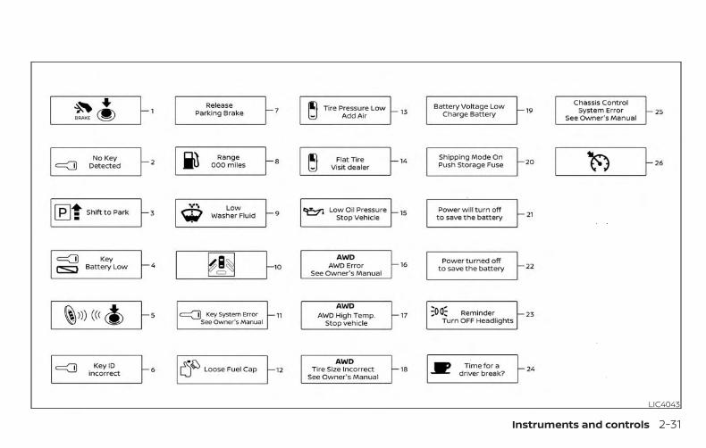
LIC4043
Instruments and controls 2-31

LIC4104
2-32 Instruments and controls

VEHICLE INFORMATION DISPLAYWARNINGS AND INDICATORS
1. Hybrid system start operation
2. No Key Detected
3. Shift to Park
4. Key Battery Low
5. Hybrid system start operation for Intel-ligent Key system (if I-Key battery levelis low)
6. Key ID Incorrect
7. Release Parking Brake
8. Low Fuel
9. Low Washer Fluid (if so equipped)
10. Door/liftgate Open
11. Key System Error: See Owner’s Manual
12. Loose Fuel Cap
13. Tire Pressure Low — Add Air
14. Flat Tire — Visit dealer (if so equipped)
15. Low Oil Pressure Stop Vehicle
16. AWD Error: See Owner’s Manual(if so equipped)
17. AWD High Temp. Stop vehicle(if so equipped)
18. AWD Tire Size Incorrect: See Owner’sManual (if so equipped)
19. Battery Voltage Low Charge Battery
20. Shipping Mode On Push Storage Fuse
21. Power will turn off to save the battery
22. Power turned off to save the battery
23. Reminder: Turn OFF Headlights
24. Timer Alert — Time for a driver break?
25. Chassis Control System Error: SeeOwner’s Manual
26. Cruise control indicator (if so equipped)
27. Intelligent Cruise Control (ICC) indica-tors (if so equipped)
28. Transmission Shift Position Indicator
29. CVT Error: See Owner’s Manual
30. Malfunction: See Owner’s Manual(if so equipped)
31. Drive mode indicators
32. High Coolant Temp Stop Vehicle
33. Hybrid System Overheated StopVehicle
34. Headlight System Error: See Owner’sManual (if so equipped)
35. Side Radar Obstruction
36. Unavailable: Front Radar Obstruction(if so equipped)
37. Shift to Park Li-ion battery low
38. HV System Warm up Please Wait in Park
39. Unavailable: Road is slippery(if so equipped)
40. Unavailable: VDC OFF
41. Unavailable: High Cabin Temp(if so equipped)
42. Lane Departure Warning (LDW)indicator (if so equipped)
43. Intelligent Lane Intervention (I-LI)indicator (if so equipped)
44. Rear Door Alert is activated
45. Check Rear Seat for All Articles
46. Rear Automatic Braking (RAB) systemwarning indicator (if so equipped)
47. Blind Spot Warning (BSW) indicator
48. Rear Sonar System (RSS) indicator(if so equipped)
Instruments and controls 2-33
49. Parking Sensor Error: See Owner’sManual (if so equipped)
50. Automatic Emergency Braking (AEB)emergency warning indicator
51. System Fault (if so equipped)
Hybrid system start operation
This indicator appears when the shift leveris in the P (Park) position.
This indicator means that the hybrid sys-tem will start by pushing the ignition switchwith the brake pedal depressed. You canstart the hybrid system from any positionof the ignition switch.
No Key Detected
This warning appears when the IntelligentKey is left outside the vehicle with the igni-tion switch in the ON position. Make surethe Intelligent Key is inside the vehicle.
For additional information, refer to “NISSANIntelligent Key®” in the “Pre-driving checksand adjustments” section of this manual.
Shift to Park
This warning illuminates when the ignitionswitch is in the OFF position and the shift
lever is not in the P (Park) position. Also, achime sounds when the ignition switch isin the OFF position.
If this warning illuminates, move the shiftlever to the P (Park) position and start thehybrid system.
Key Battery Low
This indicator illuminates when the Intelli-gent Key battery is running out of power.
If this indicator illuminates, replace the bat-tery with a new one. For additional infor-mation, refer to “Battery replacement” inthe “Do-it-yourself ” section of this manual.
Hybrid system start operation for Intel-ligent Key system (if I-Key battery levelis low)
This indicator appears when the battery ofthe Intelligent Key is low and when the In-telligent Key system and the vehicle are notcommunicating normally.
If this appears, touch the ignition switchwith the Intelligent Key while depressingthe brake pedal. For additional information,refer to “NISSAN Intelligent Key® battery dis-charge” in the “Starting and driving” sectionof this manual.
Key ID Incorrect
This warning appears when the ignitionswitch is placed from the OFF position andthe Intelligent Key is not recognized by thesystem. You cannot start the hybrid sys-tem with an unregistered key.
For additional information, refer to “NISSANIntelligent Key®” in the “Pre-driving checksand adjustments” section of this manual.
Release Parking Brake
This warning illuminates in the messagearea of the vehicle information displaywhen the parking brake is set and the ve-hicle is driven.
Low Fuel
This warning illuminates when the fuel levelin the fuel tank is getting low. Refuel assoon as it is convenient, preferably beforethe fuel gauge reaches 0 (Empty). Therewill be a small reserve of fuel in the tankwhen the fuel gauge needle reaches 0(Empty).
Low Washer Fluid (if so equipped)
This warning illuminates when thewindshield-washer fluid is at a low level.Add windshield-washer fluid as necessary.For additional information, refer to
2-34 Instruments and controls

“Windshield-washer fluid” in the “Do-it-yourself ” section of this manual.
Door/liftgate Open
This warning illuminates when a door orthe liftgate has been opened.
Key System Error: See Owner’s Manual
After the ignition switch is pushed to theON position, this light comes on for a periodof time and then turns off.
The Key System Error message warns of amalfunction with the Intelligent Key sys-tem. If the light comes on while the hybridsystem is stopped, it may be impossible tostart the hybrid system.
If the light comes on while the hybrid sys-tem is running, you can drive the vehicle.However in these cases, have the systemchecked. It is recommended that you visit aNISSAN dealer for this service.
Loose Fuel Cap
This warning appears when the fuel-fillercap is not tightened correctly after the ve-hicle has been refueled. For additional in-formation, refer to “Fuel-filler cap” in the“Pre-driving checks and adjustments” sec-tion of this manual.
Tire Pressure Low - Add Air
This warning appears when the low tirepressure warning light in the meter illumi-nates and low tire pressure is detected. Thewarning appears each time the ignitionswitch is placed in the ON position as long asthe low tire pressure warning light remainsilluminated. If this warning appears, stop thevehicle and adjust the tire pressures of allfour tires to the recommended COLD tirepressure shown on the Tire and Loading In-formation label. For additional information,refer to “Low tire pressure warning light” inthis section and “Tire Pressure MonitoringSystem (TPMS)” in the “Starting and driving”section of this manual.
Flat Tire – Visit dealer (if so equipped)
This warning appears when the low tirepressure warning light in the meter illumi-nates and one or more flat tires are de-tected while driving. A chime also soundsfor approximately 10 seconds.
Low Oil Pressure Stop Vehicle
This warning appears in the message areaof the vehicle information display if low oilpressure is detected. This gauge is not de-signed to indicate low oil level. The low oilpressure warning is not designed to indi-
cate a low oil level. Use the dipstick tocheck the oil level. For additional informa-tion, refer to “Engine oil” in the “Do-it-yourself ” section of this manual.
AWD Error: See Owner’s Manual (if soequipped)
This warning appears when the all-wheeldrive system is not functioning properlywhile the hybrid system is running.
AWD High Temp. Stop vehicle (if soequipped)
This warning may appear while trying tofree a stuck vehicle due to increased oiltemperature. The driving mode maychange to 2-Wheel Drive (2WD). If this warn-ing is displayed, stop the vehicle with theengine idling, as soon as it is safe to do so.Then if the warning turns off, you can con-tinue driving.
AWD Tire Size Incorrect: See Owner’sManual (if so equipped)
This warning may appear if there is a largedifference between the diameters of thefront and rear wheels. Pull off the road in asafe area, with the engine idling. Check thatall the tire sizes are the same, that the tirepressure is correct and that the tires arenot excessively worn.
Instruments and controls 2-35

Battery Voltage Low Charge Battery
This warning appears when the battery islow and needs to be charged.
Shipping Mode On Push Storage Fuse
This warning may appear if the extendedstorage switch is not pushed in. When thiswarning appears, push in the extendedstorage switch to turn off the warning. Foradditional information, refer to “Extendedstorage switch” in this section.
Power will turn off to save the battery
This warning appears in the message areaof the vehicle information display after aperiod of time if the shift lever has notmoved from the P (Park) position.
Power turned off to save the battery
This message appears after the ignitionswitch is automatically turned to off tosave the 12–volt battery. For additional in-formation, refer to “Push-button ignitionswitch positions” in the “Starting and driv-ing” section of this manual.
Reminder: Turn OFF Headlights
This warning appears when the headlightsare left in the ON position when exiting thevehicle. Place the headlight switch in theOFF or AUTO position. For additional infor-mation, refer to “Headlight and turn signalswitch” in this section.
Timer Alert – Time for a driver break?
This indicator appears when the set time isreached. The time can be set up to sixhours. For additional information on set-ting the timer, refer to “Alarm” in this sec-tion.
Chassis Control System Error: See Own-er’s Manual
This warning appears if the IntegratedDynamics-control Module detects an errorin the Intelligent Trace Control, IntelligentEngine Brake, or the Active Ride Controlsystems. Have the system checked. It isrecommended that you visit a NISSANdealer for this service. For additional infor-mation, refer to “Chassis control” in the“Starting and driving” section of thismanual.
Cruise control indicator (if so equipped)
This indicator shows the cruise control sys-tem status.
For additional information, refer to “Cruisecontrol” in the “Starting and driving” sectionof this manual.
Intelligent Cruise Control (ICC) indica-tors (if so equipped)
These indicators show the IntelligentCruise Control (ICC) system status. The sta-tus is shown by color. For additional infor-mation, refer to “Intelligent Cruise Control(ICC)” in the “Starting and driving” section ofthis manual.
Transmission Shift Position Indicator
This indicator shows the transmission shiftposition.
CVT Error: See Owner’s Manual
This warning illuminates when there is aproblem with the CVT system. If this warn-ing comes on, have the system checked. Itis recommended that you visit a NISSANdealer for this service.
2-36 Instruments and controls

Malfunction: See Owner’s Manual (if soequipped)
This warning appears when one or more ofthe following systems (if so equipped) isnot functioning properly:
∙ Automatic Emergency Braking (AEB)
∙ Automatic Emergency Braking (AEB)with Pedestrian Detection
∙ Rear Automatic Braking (RAB)
∙ Lane Departure Warning (LDW)
∙ Blind Spot Warning (BSW)
∙ Intelligent Cruise Control (ICC)
If one or more of these warning appears,have the system checked. It is recom-mended that you visit a NISSAN dealer forthis service.
Drive mode indicators
These indicators illuminate in the vehicleinformation display when either the ECO orSPORT modes are selected.
For additional information, refer to “SPORTmode switch” or “ECO mode switch” in the“Starting and driving” or the section of thismanual.
High Coolant Temp Stop Vehicle
This warning appears when the tempera-ture of the engine coolant is too high. Stopthe vehicle in a safe location as soon aspossible. Avoid quick starting or abrupt ac-celeration. When the warning turns off, thevehicle can be driven.
If the warning appears again soon after itturns off, have the system checked. It isrecommended that you visit a NISSANdealer for this service.
Hybrid System Overheated Stop Vehicle
This warning appears when the tempera-ture of the hybrid system is too high. Stopthe vehicle in a safe location as soon aspossible. Avoid quick starting or abrupt ac-celeration. When the warning turns off, thevehicle can be driven.
If the warning appears again soon after itturns off, have the system checked. It isrecommended that you visit a NISSANdealer for this service.
Do not drive the vehicle with the warningon. Doing so could cause a hybrid systemmalfunction.
WARNINGIf you continue to drive the vehicle whilethe warning is displayed, the hybridsystem may become temporarily inop-erative and the system cannot providepower to the wheels. This can result inreduced or zero vehicle speed. The re-duced speed or zero speed may belower than other traffic, which could in-crease the chance of a collision. If thevehicle cannot maintain a safe drivingspeed, pull to the side of the road in asafe area. If this occurs, place the shiftlever in the P (Park) position and theignition in the READY to drive positionwith the vehicle stopped until the dis-play turns off. The Hybrid System Over-heated warning and the SHIFT “P”warning messages will be alternatelydisplayed. For additional information,refer to the “Shift to Park” warning inthis section.
Instruments and controls 2-37

Headlight System Error: See Owner’sManual (if so equipped)
This warning appears when there is an er-ror with the system. For additional informa-tion, refer to “Headlight and turn signalswitch” in this section.
Side Radar Obstruction
This message appears when the BlindSpot Warning (BSW)/Rear Cross Traffic Alert(RCTA) systems become unavailable be-cause a radar blockage is detected. Foradditional information, refer to “Blind SpotWarning (BSW)” or “Rear Cross Traffic Alert(RCTA)” in the “Starting and driving” sectionof this manual.
Unavailable: Front Radar Obstruction (ifso equipped)
This message appears when the IntelligentCruise Control (ICC) system, the AutomaticEmergency Braking (AEB) system or theAutomatic Emergency Braking (AEB) withPedestrian Detection system becomes un-available because the front radar is ob-structed. For additional information, referto “Intelligent Cruise Control (ICC)”, “Auto-matic Emergency Braking (AEB)” or “Auto-matic Emergency Braking (AEB) with Pe-
destrian Detection” in the “Starting anddriving” section of this manual.
Shift to Park Li-ion battery low
This warning appears when the shift leveris in the N (Neutral) position and the level ofremaining charge in the Li-ion battery islow. When this warning appears, place theshift lever in the P (Park) position.This will turn off in the following condi-tion(s):
∙ When the shift lever has been placed inthe P (Park) position.
HV System Warm up Please Wait In Park
This warning appears when the hybrid sys-tem has not reached full operating tem-perature. When the warning turns off, thevehicle can be driven.
Unavailable: Road is slippery (if soequipped)
This message appears when the IntelligentLane Intervention (I-LI) system becomesunavailable because the road is slippery.For additional information, refer to “ Intelli-gent Lane Intervention (I-LI)” in the “Startingand driving” section of this manual.
Unavailable: VDC OFF (if so equipped)
This message appears when the IntelligentLane Intervention (I-LI) system becomesunavailable because the VDC is turned off.For additional information, refer to “ Intelli-gent Lane Intervention (I-LI)” in the “Startingand driving” section of this manual.
Unavailable: High Cabin Temp. (if soequipped)
This message appears when the cameradetects an interior temperature of morethan approximately 104°F (40°C). For addi-tional information, refer to “Lane DepartureWarning (LDW)” and “Intelligent Lane Inter-vention (I-LI)” in the “Starting and driving”section of this manual.
Lane Departure Warning (LDW) indicator(if so equipped)
This indicator shows when the LDW andIntelligent Lane Intervention (I-LI) systemsare engaged.
For additional information, refer to “LaneDeparture Warning (LDW) system” and “In-telligent Lane Intervention (I-LI)” in the“Starting and driving” section of thismanual.
2-38 Instruments and controls

Intelligent Lane Intervention (I-LI) indi-cator (if so equipped)
This indicator shows when the I-LI systemis engaged.
For additional information, refer to “Dy-namic driver assistance switch” in this sec-tion and “Intelligent Lane Intervention (I-LI)”in the “Starting and driving” section of thismanual.
Rear Door Alert is activated
When the system is enabled, this messageappears when the Rear Door Alert systemis active and can remind the driver to checkthe back seat.
∙ Using the steering wheel switch, a drivercan select “Dismiss Message” to clearthe display for a period of time. If noselection is made, this message auto-matically turns off after a period of time.
∙ Using the steering wheel switch, a drivercan select “Disable Alert” to disable thehorn alert for the remainder of the cur-rent trip.
WARNINGSelecting “Dismiss Message” during astop within a trip temporarily dismissesthe message for that stop without turn-ing the system off. Alerts can be pro-vided for other stops during the trip. Se-lecting “Disable Alert” turns off the RearDoor Alert system for the remainder ofa trip and no audible alert will beprovided.
NOTE:
This system is disabled until a driver en-ables it using the vehicle informationdisplay. For additional information, referto “How to use the vehicle informationdisplay” in this section.
For additional information, refer to “RearDoor Alert” in this section.
Check Rear Seat For All Articles
When the system is enabled, this messageappears when the vehicle comes to a com-plete stop, the vehicle is transitioned fromthe D (Drive) position to P (Park) position,and the driver exits the vehicle. This mes-sage alerts the driver, after a period of time,to check for items in the rear seat after theaudible alert has been provided.
NOTE:
This system is disabled until a driver en-ables it using the vehicle informationdisplay. For additional information, referto “How to use the vehicle informationdisplay” in this section.
For additional information, refer to “RearDoor Alert” in this section.
Rear Automatic Braking (RAB) systemwarning indicator (if so equipped)
This indicator illuminates to indicate thestatus of the Rear Automatic Braking (RAB)system. For additional information, refer to“Rear Automatic Braking (RAB) system” inthe “Starting and driving” section of thismanual.
Blind Spot Warning (BSW) indicator (ifso equipped)
This indicator shows when the BSW systemis engaged.
For additional information, refer to “BlindSpot Warning (BSW)” in the “Starting anddriving” section of this manual.
Instruments and controls 2-39

Rear Sonar System (RSS) indicator (if soequipped)
This indicator illuminates to indicate thestatus of the RSS. For additional informa-tion, refer to “Rear Sonar System (RSS)” inthe “Starting and driving” section of thismanual.
Parking Sensor Error: See Owner’sManual (if so equipped)
This warning illuminates when there is anerror with the system. For additional infor-mation, refer to “Rear Sonar System (RSS)”in the “Starting and driving” section of thismanual.
Automatic Emergency Braking (AEB)emergency warning indicator (if soequipped)
This indicator illuminates along, with an au-dible warning, when the system detectsthe possibility of a forward collision.
For additional information, refer to “Auto-matic Emergency Braking (AEB)” in the“Starting and driving” section of thismanual.
System Fault (if so equipped)
This warning appears if there is a malfunc-tion in the Rear Automatic Braking (RAB)system. For additional information, refer to“Rear Automatic Braking (RAB)” in the “Start-ing and driving” section of this manual.
Your vehicle may have two types of securitysystems:
∙ Vehicle security system
∙ NISSAN Vehicle Immobilizer System
VEHICLE SECURITY SYSTEMThe vehicle security system provides visualand audible alarm signals if someoneopens the doors or liftgate when the sys-tem is armed. It is not, however, a motiondetection type system that activates whena vehicle is moved or when a vibration oc-curs.
LIC2385
SECURITY SYSTEMS
2-40 Instruments and controls

The system helps deter vehicle theft butcannot prevent it, nor can it prevent thetheft of interior or exterior vehicle compo-nents in all situations. Always secure yourvehicle even if parking for a brief period.Never leave your keys in the vehicle, andalways lock the vehicle when unattended.Be aware of your surroundings, and park insecure, well-lit areas whenever possible.
Many devices offering additional protec-tion, such as component locks, identifica-tion markers, and tracking systems, areavailable at auto supply stores and spe-cialty shops. A NISSAN dealer may also offersuch equipment. Check with your insur-ance company to see if you may be eligiblefor discounts for various theft protectionfeatures.
How to arm the vehicle securitysystem
1. Close all windows. (The system can bearmed even if the windows are open.)
2. Remove the keys from the vehicle.
3. Close all doors and liftgate. Lock alldoors. The doors can be locked withthe key fob (if so equipped), IntelligentKey (if so equipped), door handle re-quest switch, or mechanical key (if soequipped).
4. Confirm that the security indica-tor light stays on for about 30 seconds.The vehicle security system is now pre-armed. The vehicle security system willautomatically shift into the armedphase. The security light beginsto flash once every three seconds. Ifduring the pre-armed phase one of thefollowing occurs, the system will notarm:
∙ Any door is unlocked with the key fob (ifso equipped), the Intelligent Key (if soequipped), mechanical key (if soequipped), or door request switch.
∙ Ignition switch is placed in the ON posi-tion.
∙ Even when the driver and/or passen-gers are in the vehicle, the system willactivate with all the doors, hood andliftgate locked with the ignitionswitch placed in the LOCK position.When placing the ignition switch inthe ON position, the system will bereleased.
Vehicle security system activationThe vehicle security system will give thefollowing alarm:
∙ The turn signals blink and the hornsounds intermittently.
∙ The alarm automatically turns off aftera period of time. However, the alarmreactivates if the vehicle is tamperedwith again. The alarm can be shut off byunlocking the driver’s door or liftgatewith the key (if so equipped) or by press-ing the button on the IntelligentKey.
Instruments and controls 2-41

The alarm is activated by:
∙ Opening the door or liftgate without us-ing the key (if so equipped) or IntelligentKey (even if the door is unlocked by re-leasing the door inside lock switch).
How to stop an activated alarmThe alarm stops only by unlocking a dooror the liftgate with the mechanical key (if soequipped), pressing the button onthe Intelligent Key, or pushing the requestswitch on the driver’s or passenger’s doorwith the Intelligent Key in range of the doorhandle.
NISSAN VEHICLE IMMOBILIZERSYSTEMThe NISSAN Vehicle Immobilizer Systemwill not allow the hybrid system to startwithout the use of a registered key.
Never leave these keys in the vehicle.
FCC Notice:
For USA:
This device complies with Part 15 of theFCC Rules. Operation is subject to the fol-lowing two conditions: (1) This devicemay not cause harmful interference, and(2) this device must accept any interfer-ence received, including interferencethat may cause undesired operation.
NOTE:
Changes or modifications not expresslyapproved by the party responsible forcompliance could void the user’s author-ity to operate the equipment.
For Canada:
This device complies with IndustryCanada licence-exempt RSS standard(s).Operation is subject to the following twoconditions: (1) this device may not causeinterference, and (2) this device must ac-cept any interference received, includinginterference that may cause undesiredoperation of the device.
Security indicator lightThe security indicator light blinks wheneverthe ignition switch is placed in the OFF orLOCK position.
This function indicates the NISSAN VehicleImmobilizer System is operational.
If the NISSAN Vehicle Immobilizer System ismalfunctioning, the light will remain onwhile the ignition switch is placed in the ONposition.
LIC0474
2-42 Instruments and controls

If the light still remains on and/or thehybrid system will not start, seek servicefor the NISSAN Vehicle Immobilizer Sys-tem service as soon as possible. Pleasebring all registered keys that you have. Itis recommended that you visit a NISSANdealer for this service.
SWITCH OPERATION
WARNINGIn freezing temperatures the washersolution may freeze on the windshieldand obscure your vision which may leadto an accident. Warm the windshieldwith the defroster before you wash thewindshield.
CAUTION∙ Do not operate the washer continu-
ously for more than 30 seconds.
∙ Do not operate the washer if thewindshield-washer fluid reservoir isempty.
∙ Do not fill the windshield-washer fluidreservoir with windshield-washerfluid concentrates at full strength.Some methyl alcohol basedwindshield-washer fluid concen-trates may permanently stain thegrille if spilled while filling thewindshield-washer fluid reservoir.
∙ Pre-mix windshield-washer fluid con-centrates with water to the manufac-turer’s recommended levels beforepouring the fluid into the windshield-washer fluid reservoir. Do not use thewindshield-washer fluid reservoir tomix the windshield-washer fluid con-centrate and water.
LIC2661
WIPER AND WASHER SWITCH
Instruments and controls 2-43
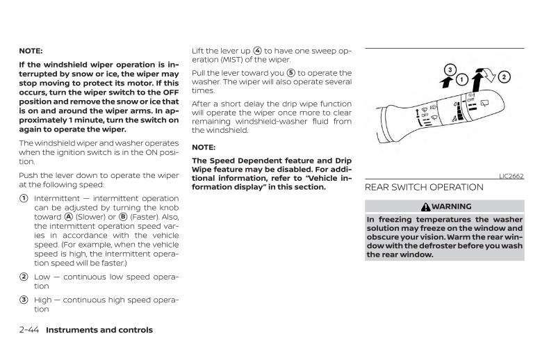
NOTE:
If the windshield wiper operation is in-terrupted by snow or ice, the wiper maystop moving to protect its motor. If thisoccurs, turn the wiper switch to the OFFposition and remove the snow or ice thatis on and around the wiper arms. In ap-proximately 1 minute, turn the switch onagain to operate the wiper.
The windshield wiper and washer operateswhen the ignition switch is in the ON posi-tion.
Push the lever down to operate the wiperat the following speed:
�1 Intermittent — intermittent operationcan be adjusted by turning the knobtoward �A (Slower) or �B (Faster). Also,the intermittent operation speed var-ies in accordance with the vehiclespeed. (For example, when the vehiclespeed is high, the intermittent opera-tion speed will be faster.)
�2 Low — continuous low speed opera-tion
�3 High — continuous high speed opera-tion
Lift the lever up �4 to have one sweep op-eration (MIST) of the wiper.
Pull the lever toward you �5 to operate thewasher. The wiper will also operate severaltimes.
After a short delay the drip wipe functionwill operate the wiper once more to clearremaining windshield-washer fluid fromthe windshield.
NOTE:
The Speed Dependent feature and DripWipe feature may be disabled. For addi-tional information, refer to “Vehicle in-formation display” in this section. REAR SWITCH OPERATION
WARNINGIn freezing temperatures the washersolution may freeze on the window andobscure your vision. Warm the rear win-dow with the defroster before you washthe rear window.
LIC2662
2-44 Instruments and controls

CAUTION∙ Do not operate the washer continu-
ously for more than 30 seconds.
∙ Do not operate the washer if thewindshield-washer fluid reservoir isempty.
∙ Do not fill the windshield-washer fluidreservoir with windshield-washerfluid concentrates at full strength.Some methyl alcohol basedwindshield-washer fluid concen-trates may permanently stain thegrille if spilled while filling thewindshield-washer fluid reservoir.
∙ Pre-mix windshield-washer fluid con-centrates with water to the manufac-turer’s recommended levels beforepouring the fluid into the windshield-washer fluid reservoir. Do not use thewindshield-washer fluid reservoir tomix the windshield-washer fluid con-centrate and water.
NOTE:
If the rear window wiper operation is in-terrupted by snow, etc., the wiper maystop moving to protect its motor. If thisoccurs, turn the wiper switch to OFF andremove the snow, etc. on and around thewiper arms. After about 1 minute, turnthe switch ON again to operate the wiper.
The rear window wiper and washer oper-ate when the ignition switch is in the ONposition. Turn the switch clockwise fromthe OFF position to operate the wiper.
�1 Intermittent (INT) — intermittent op-eration (not adjustable)
�2 Low (ON) — continuous low speed op-eration
Push the switch forward �3 to operate thewasher. The wiper will also operate severaltimes.
NOTE:
The Reverse Link feature may be dis-abled. For additional information, referto “Vehicle information display” in thissection.
To defrost the rear window glass and out-side mirrors start the hybrid system andpush the rear window defroster switch on.The rear window defroster indicator lighton the switch comes on. Push the switchagain to turn the defroster off.
The rear window defroster automaticallyturns off after approximately 15 minutes.
CAUTIONWhen cleaning the inner side of the rearwindow, be careful not to scratch ordamage the rear window defroster.
LIC2614
REAR WINDOW AND OUTSIDEMIRROR DEFROSTER SWITCH
Instruments and controls 2-45

HEADLIGHT CONTROL SWITCHLighting
�1 Rotate the switch to the position,and the front parking, tail, license plate,and instrument panel lights will comeon.
�2 Rotate the switch to the position,and the headlights will come on and allthe other lights remain on.
CAUTIONUse the headlights with the engine run-ning to avoid discharging the vehicle’s12–volt battery.
Autolight systemThe autolight system allows the headlightsto turn on and off automatically. The auto-light system can:
∙ Turn on the headlights, front parking,tail, license plate and instrument panellights automatically when it is dark.
∙ Turn off all the lights when it is light.
∙ Keep all the lights on for a period of timeafter you place the ignition switch in theOFF position and all doors are closed.
Type A (if so equipped)LIC2634
Type B (if so equipped)LIC2635 LIC2636
HEADLIGHT AND TURN SIGNALSWITCH
2-46 Instruments and controls
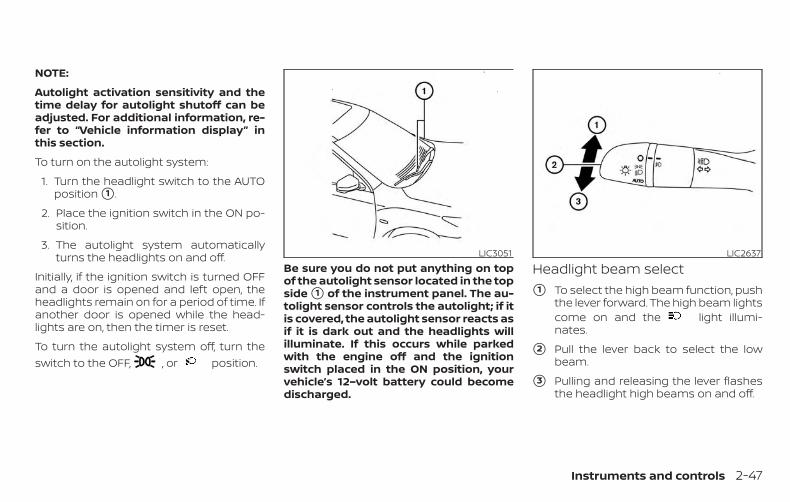
NOTE:
Autolight activation sensitivity and thetime delay for autolight shutoff can beadjusted. For additional information, re-fer to “Vehicle information display” inthis section.
To turn on the autolight system:
1. Turn the headlight switch to the AUTOposition �1 .
2. Place the ignition switch in the ON po-sition.
3. The autolight system automaticallyturns the headlights on and off.
Initially, if the ignition switch is turned OFFand a door is opened and left open, theheadlights remain on for a period of time. Ifanother door is opened while the head-lights are on, then the timer is reset.
To turn the autolight system off, turn theswitch to the OFF, , or position.
Be sure you do not put anything on topof the autolight sensor located in the topside �1 of the instrument panel. The au-tolight sensor controls the autolight; if itis covered, the autolight sensor reacts asif it is dark out and the headlights willilluminate. If this occurs while parkedwith the engine off and the ignitionswitch placed in the ON position, yourvehicle’s 12–volt battery could becomedischarged.
Headlight beam select�1 To select the high beam function, push
the lever forward. The high beam lightscome on and the light illumi-nates.
�2 Pull the lever back to select the lowbeam.
�3 Pulling and releasing the lever flashesthe headlight high beams on and off.
LIC3051 LIC2637
Instruments and controls 2-47

High Beam AssistThe High Beam Assist system will operatewhen the vehicle is driven at speeds of ap-proximately 25 mph (40 km/h) and above. Ifan oncoming vehicle or leading vehicle ap-pears in front of your vehicle when theheadlight high beam is on, the headlightwill be switched to the low beam automati-cally.
WARNING∙ The High Beam Assist system is a con-
venience but it is not a substitute forsafe driving operation. The drivershould remain alert at all times, en-sure safe driving practices and switchthe high beams and low beam manu-ally when necessary.
∙ The high beam or low beam may notswitch automatically under the fol-lowing conditions. Switch the highbeam and low beam manually.
– During bad weather (rain, fog,snow, wind, etc.).
– When a light source similar to aheadlight or tail light is in the vicin-ity of the vehicle.
– When the headlights of the on-coming vehicle or the leading ve-hicle are turned off, when the colorof the light is affected due to for-eign materials on the lights, orwhen the light beam is out ofposition.
– When there is a sudden, continu-ous change in brightness.
– When driving on a road that passesover rolling hills, or a road that haslevel differences.
– When driving on a road with manycurves.
– When a sign or mirror-like surfaceis reflecting intense light towardsthe front of the vehicle.
– When the container, etc. beingtowed by a leading vehicle is re-flecting intense light.
– When a headlight on your vehicle isdamaged or dirty.
– When the vehicle is leaning at anangle due to a punctured tire, be-ing towed, etc.
∙ The timing of switching the low beamand high beam may change under thefollowing situations.
– The brightness of the headlights ofthe oncoming vehicle or leadingvehicle.
– The movement and direction ofthe oncoming vehicle and the lead-ing vehicle.
– When only one light on the oncom-ing vehicle or the leading vehicle isilluminated.
– When the oncoming vehicle or theleading vehicle is a two-wheeledvehicle.
– Road conditions (incline, curve, theroad surface, etc.).
– The number of passengers and theamount of luggage.
2-48 Instruments and controls

High Beam Assist operation
To activate the High Beam Assist system,turn the headlight switch to the AUTO po-sition �1 and push the lever forward �2(high beam position). The High Beam Assistindicator light in the meter will illuminatewhile the headlights are turned on.
If the High Beam Assist indicator light doesnot illuminate in the above condition, it mayindicate that the system is not functioningproperly. Have the system checked, it isrecommended that you visit a NISSANdealer for this service.
When the vehicle speed lowers to less thanapproximately 16 mph (25 km/h), the head-light uses the low beam.To turn off the High Beam Assist system,turn the headlight switch to the posi-tion or select the low beam position byplacing the lever in the neutral position.
Ambient image sensor maintenanceThe ambient image sensor �1 for the HighBeam Assist system is located in front ofthe inside mirror. To maintain the properoperation of the high beam assist systemand prevent a system malfunction, be sureto observe the following:
∙ Always keep the windshield clean.
∙ Do not attach a sticker (including trans-parent material) or install an accessorynear the ambient image sensor.
LIC3696 LSD2712
Instruments and controls 2-49
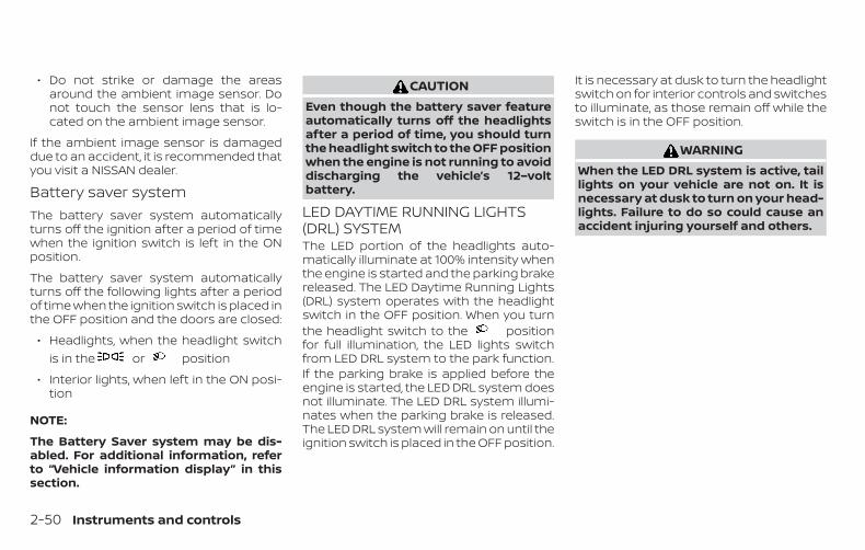
∙ Do not strike or damage the areasaround the ambient image sensor. Donot touch the sensor lens that is lo-cated on the ambient image sensor.
If the ambient image sensor is damageddue to an accident, it is recommended thatyou visit a NISSAN dealer.
Battery saver systemThe battery saver system automaticallyturns off the ignition after a period of timewhen the ignition switch is left in the ONposition.
The battery saver system automaticallyturns off the following lights after a periodof time when the ignition switch is placed inthe OFF position and the doors are closed:
∙ Headlights, when the headlight switchis in the or position
∙ Interior lights, when left in the ON posi-tion
NOTE:
The Battery Saver system may be dis-abled. For additional information, referto “Vehicle information display” in thissection.
CAUTIONEven though the battery saver featureautomatically turns off the headlightsafter a period of time, you should turnthe headlight switch to the OFF positionwhen the engine is not running to avoiddischarging the vehicle’s 12–voltbattery.
LED DAYTIME RUNNING LIGHTS(DRL) SYSTEMThe LED portion of the headlights auto-matically illuminate at 100% intensity whenthe engine is started and the parking brakereleased. The LED Daytime Running Lights(DRL) system operates with the headlightswitch in the OFF position. When you turnthe headlight switch to the positionfor full illumination, the LED lights switchfrom LED DRL system to the park function.If the parking brake is applied before theengine is started, the LED DRL system doesnot illuminate. The LED DRL system illumi-nates when the parking brake is released.The LED DRL system will remain on until theignition switch is placed in the OFF position.
It is necessary at dusk to turn the headlightswitch on for interior controls and switchesto illuminate, as those remain off while theswitch is in the OFF position.
WARNINGWhen the LED DRL system is active, taillights on your vehicle are not on. It isnecessary at dusk to turn on your head-lights. Failure to do so could cause anaccident injuring yourself and others.
2-50 Instruments and controls

INSTRUMENT BRIGHTNESSCONTROLPress the “-” button �A to decrease thebrightness of instrument panel lights.
Press the “+” button �B to increase thebrightness of instrument panel lights.
TURN SIGNAL SWITCHTurn signal
�1 Move the lever up or down to signal theturning direction. When the turn iscompleted, the turn signal cancels au-tomatically.
Lane change signal
�2 Move the lever up or down until theturn signal begins to flash, but the leverdoes not latch, to signal a lane change.Hold the lever until the lane change iscompleted.
Move the lever up or down until theturn signal begins to flash, but the leverdoes not latch, and release the lever.The turn signal will automatically flashthree times.
Choose the appropriate method to signala lane change based on road and trafficconditions.
NOTE:
The 3 flash pass feature may be disabled.For additional information, refer to “Ve-hicle information display” in this section.
LIC2624 LIC2638
Instruments and controls 2-51

FOG LIGHT SWITCH (if soequipped)To turn the fog lights on, turn the headlightswitch to the position, then turn thefog light switch to the position.To turn the fog lights on with the headlightswitch in the AUTO position, the headlightsmust be on, then turn the fog light switch tothe position.To turn the fog lights off, turn the fog lightswitch to the OFF position.
The headlights must be on and the lowbeams selected for the fog lights to oper-ate. The fog lights automatically turn offwhen the high beam headlights are se-lected.
To sound the horn, push near the horn iconon the steering wheel.
WARNINGDo not disassemble the horn. Doing socould affect proper operation of thesupplemental front air bag system.Tampering with the supplemental frontair bag system may result in seriouspersonal injury.
LIC2639 LIC3568
HORN
2-52 Instruments and controls

WARNINGDo not use or allow occupants to usethe seat heater if you or the occupantscannot monitor elevated seat tempera-tures or have an inability to feel pain inbody parts that contact the seat. Use ofthe seat heater by such people couldresult in serious injury.
CAUTION∙ The 12–volt battery could run down if
the seat heater is operated while theengine is not running.
∙ Do not use the seat heater for ex-tended periods or when no one is us-ing the seat.
∙ Do not put anything on the seat whichinsulates heat, such as a blanket,cushion, seat cover, etc. Otherwise,the seat may become overheated.
∙ Do not place anything hard or heavyon the seat or pierce it with a pin orsimilar object. This may result in dam-age to the heater.
∙ Any liquid spilled on the heated seatshould be removed immediately witha dry cloth.
∙ When cleaning the seat, never usegasoline, benzine, thinner, or anysimilar materials.
∙ If any malfunctions are found or theheated seat does not operate, turnthe switch off and have the systemchecked. It is recommended that youvisit a NISSAN dealer for this service.
The front seats are warmed by built-inheaters.
1. Start the hybrid system.
2. Push the LO or HI position of the switch,as desired. The indicator light in theswitch will illuminate.
The heater is controlled by a thermo-stat, automatically turning the heateron and off. The indicator light will re-main on as long as the switch is on.
3. When the seat is warmed or before youleave the vehicle, be sure to push theswitch to turn it off.
LIC3475
HEATED SEAT SWITCHES
Instruments and controls 2-53

The heated steering wheel system is de-signed to operate only when the surfacetemperature of the steering wheel is below68°F (20°C).
Push the heated steering wheel switch towarm the steering wheel after the hybridsystem starts. The indicator light will comeon.
If the surface temperature of the steeringwheel is below 68°F (20°C), the system willheat the steering wheel and cycle off andon to maintain a temperature above 68°F(20°C). The indicator light will remain on aslong as the system is on.
Push the switch again to turn the heatedsteering wheel system off manually. Theindicator light will go off.
NOTE:
If the surface temperature of the steer-ing wheel is above 68°F (20°C) when theswitch is turned on, the system will notheat the steering wheel. This is not amalfunction.
The dynamic driver assistance switch isused to temporarily turn on and off theIntelligent Lane Intervention (I-LI) systemthat is activated using the settings menu ofthe vehicle information display.
The I-LI system must be turned on with thedynamic driver assistance switch everytime the ignition is placed in the ON posi-tion.
When the dynamic driver assistanceswitch is turned off, the indicator �1 on theswitch is off. The indicator will also be off ifthe I-LI system is deactivated using the ve-hicle information display.
LIC0421 LIC3681
HEATED STEERING WHEEL SWITCH (ifso equipped)
DYNAMIC DRIVER ASSISTANCESWITCH (if so equipped)
2-54 Instruments and controls

The I-LI system warns the driver with awarning light and a chime, and helps assistthe driver to return the vehicle to the centerof the traveling lane by applying the brakesto the left or right wheels individually (for ashort period of time). For additional infor-mation, refer to “Intelligent Lane Interven-tion (I-LI)” in the “Starting and driving” sec-tion and “Vehicle information display” in the“Instruments and controls” section of thismanual.
The vehicle should be driven with the VDCsystem on for most driving conditions.
If the vehicle is stuck in mud or snow, theVDC system reduces the engine output toreduce wheel spin. The engine speed willbe reduced even if the accelerator is de-pressed to the floor. If maximum enginepower is needed to free a stuck vehicle,turn the VDC system off.
To turn off the VDC system, push the VDCOFF switch. The indicator and the Au-tomatic Emergency Braking (AEB) or Auto-matic Emergency Braking (AEB) with Pe-destrian Detection system warning lightwill come on.Push the VDC OFF switch again or restartthe engine to turn on the system. For addi-tional information, refer to “Vehicle Dy-namic Control (VDC) system”, “AutomaticEmergency Braking (AEB) and “AutomaticEmergency Braking (AEB) with PedestrianDetection” in the “Starting and driving” sec-tion of this manual.
LIC3344
VEHICLE DYNAMIC CONTROL (VDC)OFF SWITCH
Instruments and controls 2-55

The All-Wheel Drive (AWD) LOCK switch islocated on the instrument panel. The AWDLOCK indicator light will illuminate whenthe switch is turned on. For additional infor-mation, refer to “Warning lights, indicatorlights and audible reminders” in this sec-tion and “AWD Lock Switch Operations” inthe “Starting and driving” section of thismanual.
Each time you push the switch, the AWDmode will switch: AUTO →LOCK → AUTO.
The Rear Door Alert system functions un-der certain conditions to indicate theremay be an object or passenger in the rearseat(s). Check the seat(s) before exiting thevehicle.
The Rear Door Alert system is initially dis-abled. The driver can enable the systemusing the vehicle information display. Foradditional information, refer to “Vehicle in-formation display warnings and indicators”in this section.
When the system is enabled:
∙ The system is activated when a reardoor is opened and closed approxi-mately 10 minutes before the vehicle isstarted. When the vehicle is started andthe system is activated, a visual mes-sage appears in the vehicle informationdisplay. For additional information, referto “Rear Door Alert is activated” in thissection.
∙ If a rear door is opened and closed butthe vehicle is not started within approxi-mately 10 minutes, the system will notbe activated. A rear door must beopened and closed and the car startedwithin 10 minutes for the system to ac-tivate.
When the Rear Door Alert system is acti-vated and a driver exits the vehicle afterarriving at a destination:
∙ When the driver puts the vehicle in the P(Park) position, a message appears inthe vehicle information display for adriver to “Dismiss Message” or “DisableAlert” if desired.
∙ With the system enabled, when thedriver exits the vehicle, an audible alert(horn sound) will occur unless a reardoor is opened and closed within ashort time to deactivate the alert.
∙ If the doors are locked before the alert isdeactivated by opening a rear door, thehorn will sound.
∙ If the system is activated but the rearliftgate is opened before opening a reardoor, the horn will be delayed until afterthe liftgate is closed.
∙ If the audible horn alert occurs, a mes-sage will also appear in the vehicle in-formation display that states, “CheckRear Seat for All Articles”.
LIC2645
ALL-WHEEL DRIVE (AWD) LOCKSWITCH (if so equipped)
REAR DOOR ALERT
2-56 Instruments and controls

WARNING• If the driver selects “Disable Alert”, noaudible alert will be provided regard-less of rear door open/close status.
• There may be times when there is anobject or passenger in the rear seat(s)but the audible alert does not sound.For example, this may occur if the en-gine is turned off and then on again in ashort period of time during a trip, or ifrear seat passengers enter or exit thevehicle during a trip.
• The system does not directly detectobjects or passengers in the rearseat(s). Instead, it can detect when arear door is opened and closed, indicat-ing that there may be something in therear seat(s).
NOTE:
There may be times when the hornsounds but there are no objects or pas-sengers in the rear seat(s).
For additional information, refer to “RearDoor Alert is activated” in this section.
The E-call (SOS) button is used in combina-tion with a NissanConnect® Services sub-scription to call for assistance in case of anemergency.
Pressing the button will (with a paid sub-scription) reach a response specialist thatwill provide assistance based on the situa-tion described by the vehicle’s occupant. Foradditional information, or to enroll your ve-hicle, refer to www.NissanUSA.com/connect,www.Nissan.ca/NissanConnect, orwww.Nissan.ca/NissanConnect/fr or call855–426–6628.
12V OUTLETSThe power outlets are for powering electri-cal accessories such as cellular tele-phones. They are rated at 12 volt, 120W (10A)maximum.
The front and center console power outletsare powered only when the ignition switchis in the ON position.
LIC3357Instrument Panel
LIC3940
E-CALL (SOS) BUTTON (if soequipped)
POWER OUTLETS
Instruments and controls 2-57

NOTE:
∙ When the ignition switch is in the OFFposition, the front and center consolepower outlets stop delivering powerone minute after the door is openedand stays open.
∙ If the door remains closed after theignition is placed in the OFF position,the front and center console poweroutlets continue to deliver power un-til the accessory power timer haselapsed.
∙ The cargo area power outlet(s) con-tinues to deliver power normally.
CAUTION∙ The outlet and plug may be hot during
or immediately after use.
∙ Only certain power outlets are de-signed for use with a cigarette lighterunit. Do not use any other power out-let for an accessory lighter. It is rec-ommended that you visit a NISSANdealer for additional information.
∙ Do not use with accessories that ex-ceed a 12 volt, 120W (10A) power draw.
∙ Do not use double adapters or morethan one electrical accessory.
∙ Use power outlets with the enginerunning to avoid discharging the ve-hicle’s 12–volt battery.
∙ Avoid using power outlets when theair conditioner, headlights or rear win-dow defroster is on.
∙ Before inserting or disconnecting aplug, be sure the electrical accessorybeing used is turned off.
Center ConsoleLIC3909
Cargo AreaLIC2617
2-58 Instruments and controls

∙ Push the plug in as far as it will go. Ifgood contact is not made, the plugmay overheat or the internal tem-perature fuse may open.
∙ When not in use, be sure to close thecap. Do not allow water or any otherliquid to contact the outlet.
LIC3359OFF position
LIC3266
EXTENDED STORAGE SWITCH
Instruments and controls 2-59

The extended storage switch is used whenshipping the vehicle. It is located in the fusepanel on the driver’s side of the instrumentpanel. If any electrical equipment does notoperate, ensure the extended storageswitch is pushed fully in place, as shown.
To inspect the extended storage switch,ensure the ignition switch and headlightswitch are off, remove the fuse box cover�A using a suitable tool in combinationwith a cloth to avoid damaging the trim.
FRONT-DOOR POCKETS SEATBACK POCKETSThere is one seatback pocket located onthe back of the driver and passenger seats.The pockets can be used to store maps.
ON positionLIC3268 LIC2308 LIC2618
STORAGE
2-60 Instruments and controls

WARNINGTo ensure proper operation of the pas-senger’s NISSAN Advanced Air Bag Sys-tem, please observe the followingitems:
∙ Do not allow a passenger in the rearseat to push or pull on the seatbackpocket or head restraint/headrest.
∙ Do not place heavy loads heavier than9.1 lbs. (4 kg) on the seatback, headrestraint/headrest or in the seatbackpocket.
GLOVE BOXOpen the glove box by pulling the handle.
WARNINGKeep glove box lid closed while drivingto help prevent injury in an accident or asudden stop.
CONSOLE BOXTo open the console box, press in on thelever �1 and raise the lid �2 .
To close, push the lid down until the locklatches.
LIC3718 WIC1504
Instruments and controls 2-61
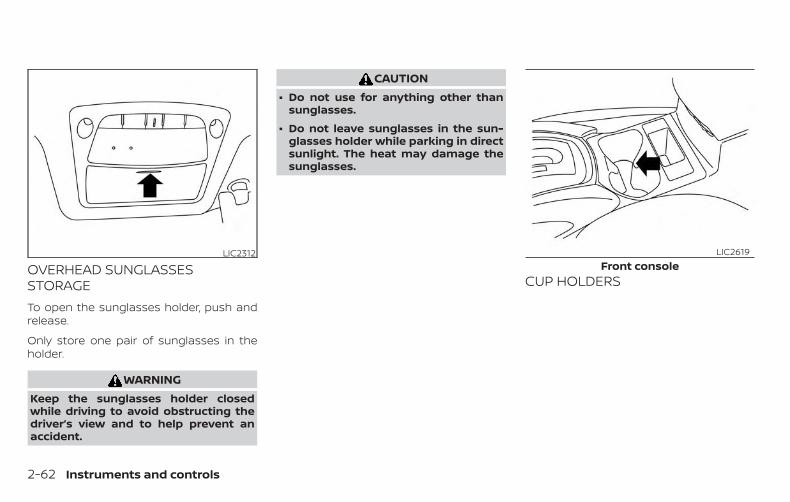
OVERHEAD SUNGLASSESSTORAGETo open the sunglasses holder, push andrelease.
Only store one pair of sunglasses in theholder.
WARNINGKeep the sunglasses holder closedwhile driving to avoid obstructing thedriver’s view and to help prevent anaccident.
CAUTION∙ Do not use for anything other than
sunglasses.
∙ Do not leave sunglasses in the sun-glasses holder while parking in directsunlight. The heat may damage thesunglasses.
CUP HOLDERS
LIC2312Front console
LIC2619
2-62 Instruments and controls

WARNING∙ Do not recline the rear seatback when
you use the cup holders on the reararmrest. Doing so may cause the bev-erages to spill over, and if they are hot,they may scald the passengers.
∙ Avoid abrupt starting and brakingwhen the cup holder is being used toprevent spilling the drink. If the liquidis hot, it can scald you or yourpassenger.
CAUTIONUse only soft cups in the cup holder.Hard objects can injure you in anaccident.
CAUTION∙ Do not use bottle holder for any other
objects that could be thrown about inthe vehicle and possibly injure peopleduring sudden braking or an accident.
∙ Do not use bottle holder for open liq-uid containers.
2nd rowLIC2656
Bottle holder — frontLIC2622
Instruments and controls 2-63

CARGO AREA STORAGE BINTo access the floor storage area, pull up onthe handle to lift the luggage board.
LUGGAGE HOOKSWhen securing items using luggage hookslocated on the back of the seat or sidefinisher do not apply a load over more than6.5 lbs. (29 N) to a single hook.
The luggage hooks that are located on thefloor should have loads less than 110 lbs.(490 N) to a single hook.
The luggage hooks can be used to securecargo with ropes or other types of straps.
Bottle holder — rearLIC2623 LIC2625 LIC3715
2-64 Instruments and controls

WARNING∙ Properly secure all cargo with ropes or
straps to help prevent it from slidingor shifting. Do not place cargo higherthan the seatbacks. In a sudden stopor collision, unsecured cargo couldcause personal injury.
∙ Use suitable ropes and hooks to se-cure cargo.
∙ Never allow anyone to ride in the lug-gage area. It is extremely dangerousto ride in a cargo area inside of a ve-hicle. In a collision, people riding inthese areas are more likely to be seri-ously injured or killed.
∙ Do not allow people to ride in any areaof your vehicle that is not equippedwith seats and seat belts.
∙ The child restraint top tether strapmay be damaged by contact withitems in the cargo area. Secure anyitems in the cargo area. Your childcould be seriously injured or killed in acollision if the top tether strap isdamaged.
∙ Be sure everyone in your vehicle is in aseat and using a seat belt properly.
CARGO COVER (if so equipped)
WARNING∙ Do not place objects on the cargo
cover while the vehicle is parked or inmotion, no matter how small. The ob-ject on the cargo cover could cause aninjury in an accident or sudden stop,and/or the cargo cover can becomedamaged.
∙ Do not leave the cargo cover in thevehicle with it disengaged from theholder.
∙ Properly secure all cargo with ropes orstraps to help prevent it from slidingor shifting. Do not place cargo higherthan the seatbacks. In a sudden stopor collision, unsecured cargo couldcause personal injury.
∙ Properly secure cargo and do not al-low it to contact the top tether strapwhen it is attached to the top tetheranchor. Cargo that is not properly se-cured or cargo that contacts the toptether strap may damage the toptether strap during a collision. If thecargo cover contacts the top tetherstrap when it is attached to the toptether anchor, remove the cargo coverfrom the vehicle or secure it on thecargo floor below its attachment lo-cation. If the cargo cover is not re-moved, it may damage the top tetherstrap during a collision. Your childcould be seriously injured or killed in acollision if the child restraint toptether strap is damaged.
Instruments and controls 2-65

The cargo cover keeps the luggage com-partment contents hidden from the out-side.
Only attach the hook and loop fastener onthe cargo cover privacy cloth to the area onthe rear seatback where it is supposed tobe attached. Otherwise, the seat surfacecould be damaged.
To remove the cargo cover:
�1 Remove the straps from the rearhatch.
�2 Remove the edge of the cargo coverprivacy cloth from the rear seatback.
�3 Remove the cargo cover holders fromthe rear pillar.
ROOF RACK (if so equipped)Do not apply any load directly to the roofside rails. Cross bars must be installed be-fore applying load/cargo/luggage to theroof of the vehicle. Genuine NISSAN acces-sory cross bars are available through aNISSAN dealer. It is recommended that youvisit a NISSAN dealer for additional informa-tion.
The service load capacity for the roof siderails is 165 lbs. (74 kg), however do not ex-ceed the accessory cross bars load capac-ity.
WIC1003
LIC2386
2-66 Instruments and controls
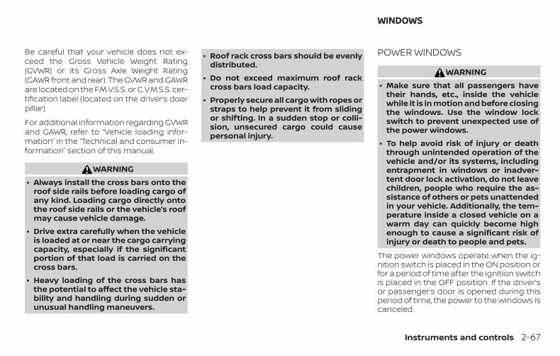
Be careful that your vehicle does not ex-ceed the Gross Vehicle Weight Rating(GVWR) or its Gross Axle Weight Rating(GAWR front and rear). The GVWR and GAWRare located on the F.M.V.S.S. or C.V.M.S.S. cer-tification label (located on the driver’s doorpillar).
For additional information regarding GVWRand GAWR, refer to “Vehicle loading infor-mation” in the “Technical and consumer in-formation” section of this manual.
WARNING∙ Always install the cross bars onto the
roof side rails before loading cargo ofany kind. Loading cargo directly ontothe roof side rails or the vehicle’s roofmay cause vehicle damage.
∙ Drive extra carefully when the vehicleis loaded at or near the cargo carryingcapacity, especially if the significantportion of that load is carried on thecross bars.
∙ Heavy loading of the cross bars hasthe potential to affect the vehicle sta-bility and handling during sudden orunusual handling maneuvers.
∙ Roof rack cross bars should be evenlydistributed.
∙ Do not exceed maximum roof rackcross bars load capacity.
∙ Properly secure all cargo with ropes orstraps to help prevent it from slidingor shifting. In a sudden stop or colli-sion, unsecured cargo could causepersonal injury.
POWER WINDOWS
WARNING∙ Make sure that all passengers have
their hands, etc., inside the vehiclewhile it is in motion and before closingthe windows. Use the window lockswitch to prevent unexpected use ofthe power windows.
∙ To help avoid risk of injury or deaththrough unintended operation of thevehicle and/or its systems, includingentrapment in windows or inadver-tent door lock activation, do not leavechildren, people who require the as-sistance of others or pets unattendedin your vehicle. Additionally, the tem-perature inside a closed vehicle on awarm day can quickly become highenough to cause a significant risk ofinjury or death to people and pets.
The power windows operate when the ig-nition switch is placed in the ON position orfor a period of time after the ignition switchis placed in the OFF position. If the driver’sor passenger’s door is opened during thisperiod of time, the power to the windows iscanceled.
WINDOWS
Instruments and controls 2-67

Driver’s side power windowswitches
1. Window lock button
2. Power door lock switch
3. Front passenger side switch
4. Right rear passenger side switch
5. Left rear passenger side switch
6. Driver side automatic switch
The driver’s side control panel is equippedwith switches to open or close all of thewindows.
To open a window, push the switch to thefirst detent and continue to hold down untilthe desired window position is reached. Toclose a window, pull the switch to the firstdetent and continue to hold up until thedesired window position is reached.
Locking passengers’ windowsWhen the window lock switch is depressed,only the driver’s side window can beopened or closed. Push it again to cancelthe window lock function.
Front passenger’s power windowswitchThe passenger’s window switch operatesonly the corresponding passenger’s win-dow. To open the window partially, push theswitch down �1 lightly until the desiredwindow position is reached. To close thewindow partially, pull the switch up �2 untilthe desired window position is reached.
LIC3208 LIC2309
2-68 Instruments and controls

Rear power window switchThe rear power window switches open orclose only the corresponding windows. Toopen the window, push the switch and holdit down �1 . To close the window, pull theswitch up �2 .
Automatic operationTo fully open a window equipped with au-tomatic operation, push the windowswitch down to the second detent and re-lease it; it need not be held. The windowautomatically opens all the way. To stopthe window, lift the switch up while the win-dow is opening.
To fully close a window equipped with au-tomatic operation, pull the switch up to thesecond detent and release it; it need not beheld. To stop the window, push the switchdown while the window is closing.
Auto-reverse functionThe auto-reverse function can be acti-vated when a window is closed by auto-matic operation.
Depending on the environment or driv-ing conditions, the auto-reverse func-tion may be activated if an impact orload similar to something being caughtin the window occurs.
WARNINGThere are some small distances imme-diately before the closed position whichcannot be detected. Make sure that allpassengers have their hands, etc., in-side the vehicle before closing thewindow.
If the vehicle’s 12–volt battery is discon-nected, replaced, or jump started, thepower window auto-reverse function maynot operate properly. If this occurs, pleasecontact the dealer to re-initialize the powerwindow auto-reverse system.
If the control unit detects somethingcaught in a window equipped with auto-matic operation, as it is closing, the windowwill be immediately lowered.
LIC2663 LIC0410
Instruments and controls 2-69
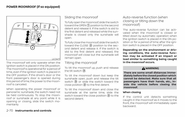
The moonroof will only operate when theignition switch is placed in the ON position.The moonroof is operational for a period oftime, even if the ignition switch is placed inthe OFF position. If the driver’s door or thefront passenger’s door is opened duringthis period of time, the power to the moon-roof is canceled.
When operating the power moonroof orpanoramic sunshade, the switch need notbe held continuously. To stop the moon-roof or sunshade at any point while it isopening or closing, slide the switch mo-mentarily.
Sliding the moonroofTo fully open the moonroof, slide the switchtoward the OPEN �1 position to the seconddetent and release it. If the switch is slid tothe first detent and released while the sun-shade is closed only the sunshade willopen.
To fully close the moonroof, slide the switchtoward the CLOSE �2 position to the sec-ond detent and release it. If the switch isslid to the first detent and released, themoonroof will close but the sunshade willremain open.
Tilting the moonroofTo tilt the moonroof up, push and releasethe tilt switch �3 .
To tilt the moonroof down but keep thesunshade open, push and release the tiltswitch �3 or slide the switch toward theclose position �2 to the first detent.
To tilt the moonroof down and close thesunshade at the same time, slide theswitch toward the close position �2 to thesecond detent.
Auto-reverse function (whenclosing or tilting down themoonroof)The auto-reverse function can be acti-vated when the moonroof is closed ortilted down by automatic operation whenthe ignition switch is placed in the ON po-sition or for a period of time after the igni-tion switch is placed in the OFF position.
Depending on the environment or driv-ing conditions, the auto-reverse func-tion may be activated if an impact orload similar to something being caughtin the moonroof occurs.
WARNINGThere are some small distances imme-diately before the closed position whichcannot be detected. Make sure that allpassengers have their hands, etc., in-side the vehicle before closing themoonroof.
When closing
If the control unit detects somethingcaught in the moonroof as it moves to thefront, the moonroof will immediately openbackward.
LIC3477
POWER MOONROOF (if so equipped)
2-70 Instruments and controls
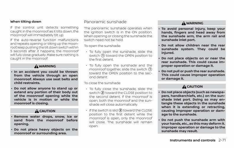
When tilting down
If the control unit detects somethingcaught in the moonroof as it tilts down, themoonroof will immediately tilt up.If the auto-reverse function malfunctionsand repeats opening or tilting up the moon-roof, keep pushing the tilt down switch within5 seconds after it happens; the moonroofwill fully close gradually. Make sure nothing iscaught in the moonroof.
WARNING∙ In an accident you could be thrown
from the vehicle through an openmoonroof. Always use seat belts andchild restraints.
∙ Do not allow anyone to stand up orextend any portion of their body outof the moonroof opening while thevehicle is in motion or while themoonroof is closing.
CAUTION∙ Remove water drops, snow, ice or
sand from the moonroof beforeopening.
∙ Do not place heavy objects on themoonroof or surrounding area.
Panoramic sunshadeThe panoramic sunshade operates whenthe ignition switch is in the ON position.When opening or closing the sunshade theswitch need not be held.
To open the sunshade:
∙ To fully open the sunshade, slide theswitch �1 toward the OPEN position tothe first detent.
∙ To fully open the sunshade and themoonroof together, slide the switch �1toward the OPEN position to the sec-ond detent.
To close the sunshade:
∙ To fully close the sunshade, slide theswitch �2 toward the CLOSE position tothe second detent. If the moonroof isopen, both the moonroof and the sun-shade will close automatically.
∙ If the switch is slid �2 toward the CLOSEposition to the first detent while themoonroof is open, only the moonroofwill close. The sunshade will remainopen.
WARNING∙ To avoid personal injury, keep your
hands, fingers and head away fromthe sunshade arm, the arm rail andsunshade inlet port.
∙ Do not allow children near the rearsunshade system. They could beinjured.
∙ Do not place objects on or near therear sunshade. This could cause im-proper operation or damage it.
∙ Do not pull or push the rear sunshade.This could cause improper operationor damage it.
CAUTION∙ Do not place objects (such as newspa-
pers, handkerchiefs, etc.) on the sun-shade inlet port. Doing so may en-tangle these objects in the sunshadewhen it is extending or retracting,causing improper operation or dam-age to the sunshade.
∙ Do not push the sunshade arm withyour hands, etc., as this may deform it.Improper operation or damage to thesunshade may result.
Instruments and controls 2-71
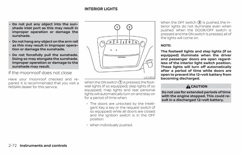
∙ Do not put any object into the sun-shade inlet port as this may result inimproper operation or damage thesunshade.
∙ Do not hang any object on the arm railas this may result in improper opera-tion or damage the sunshade.
∙ Do not forcefully pull the sunshade.Doing so may elongate the sunshade.Improper operation or damage to thesunshade may result.
If the moonroof does not closeHave your moonroof checked and re-paired. It is recommended that you visit aNISSAN dealer for this service.
When the ON switch �1 is pressed, the foot-well lights (if so equipped), step lights (if soequipped), map lights and rear personallights will automatically turn on and stay onfor a period of time when:
∙ The doors are unlocked by the Intelli-gent Key, a key or the request switch (ifso equipped) while all doors are closedand the ignition switch is in the OFFposition.
∙ When individually pushed.
When the OFF switch �2 is pushed, the in-terior lights do not illuminate even whenpushed. When the DOOR/OFF switch ispressed and the ON switch is pressed, all ofthe lights will come on.
NOTE:
The footwell lights and step lights (if soequipped) illuminate when the driverand passenger doors are open regard-less of the interior light switch position.These lights will turn off automaticallyafter a period of time while doors areopen to prevent the 12–volt battery frombecoming discharged.
CAUTIONDo not use for extended periods of timewith the engine stopped. This could re-sult in a discharged 12–volt battery.
LIC2302
INTERIOR LIGHTS
2-72 Instruments and controls
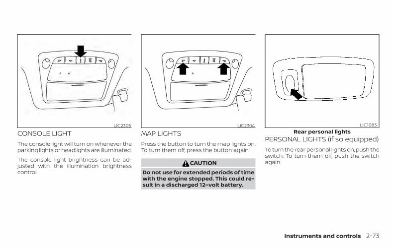
CONSOLE LIGHTThe console light will turn on whenever theparking lights or headlights are illuminated.
The console light brightness can be ad-justed with the illumination brightnesscontrol.
MAP LIGHTSPress the button to turn the map lights on.To turn them off, press the button again.
CAUTIONDo not use for extended periods of timewith the engine stopped. This could re-sult in a discharged 12–volt battery.
PERSONAL LIGHTS (if so equipped)To turn the rear personal lights on, push theswitch. To turn them off, push the switchagain.
LIC2303 LIC2304Rear personal lights
LIC1083
Instruments and controls 2-73
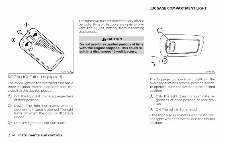
ROOM LIGHT (if so equipped)The room light on the overhead trim has athree-position switch. To operate, push theswitch to the desired position.
�1 ON: The light is illuminated, regardlessof door position.
�2 DOOR: The light illuminates when adoor or the liftgate is opened. The lightturns off when the door or liftgate isclosed.
�3 OFF: The light does not illuminate.
The lights will turn off automatically after aperiod of time while doors are open to pre-vent the 12–volt battery from becomingdischarged.
CAUTIONDo not use for extended periods of timewith the engine stopped. This could re-sult in a discharged 12–volt battery.
The luggage compartment light on theoverhead trim has a three-position switch.To operate, push the switch to the desiredposition.
�1 OFF: The light does not illuminate re-gardless of door position or lock sta-tus.
�2 ON: The light is illuminated.
• The light also illuminates with other inte-rior lights when the switch is in the neutralposition.
SIC2063A LIC3925
LUGGAGE COMPARTMENT LIGHT
2-74 Instruments and controls

CAUTIONDo not use for extended periods of timewith the engine stopped. This could re-sult in a discharged battery.
The HomeLink® Universal Transceiver pro-vides a convenient way to consolidate thefunctions of up to three individual hand-held transmitters into one built-in device.
HomeLink® Universal Transceiver:
∙ Will operate most radio frequency de-vices such as garage doors, gates,home and office lighting, entry doorlocks and security systems.
∙ Is powered by your vehicle’s battery. Noseparate batteries are required. If thevehicle’s battery is discharged or is dis-connected, HomeLink® will retain allprogramming.
When the HomeLink® Universal Trans-ceiver is programmed, retain the originaltransmitter for future programming pro-cedures (Example: new vehicle pur-chases). Upon sale of the vehicle, theprogrammed HomeLink® UniversalTransceiver buttons should be erased forsecurity purposes. For additional infor-mation, refer to “ProgrammingHomeLink®” in this section.
WARNING∙ Do not use the HomeLink® Universal
Transceiver with any garage dooropener that lacks safety stop and re-verse features as required by federalsafety standards. (These standardsbecame effective for opener modelsmanufactured after April 1, 1982). Agarage door opener which cannot de-tect an object in the path of a closinggarage door and then automaticallystop and reverse, does not meet cur-rent federal safety standards. Using agarage door opener without thesefeatures increases the risk of seriousinjury or death.
∙ During the programming procedureyour garage door or security gate willopen and close (if the transmitter iswithin range). Make sure that peopleor objects are clear of the garage door,gate, etc. that you are programming.
HOMELINK® UNIVERSALTRANSCEIVER (if so equipped)
Instruments and controls 2-75

∙ Your vehicle’s engine should beturned off while programming theHomeLink® Universal Transceiver. Donot breathe exhaust gases; they con-tain colorless and odorless carbonmonoxide. Carbon monoxide is dan-gerous. It can cause unconsciousnessor death.
PROGRAMMING HOMELINK®If you have any questions or are havingdifficulty programming your HomeLink®buttons, refer to the HomeLink® web site at:www.homelink.com or call 1-800-355-3515.
NOTE:
Place the ignition switch in the ACC posi-tion (if so equipped) when programmingHomeLink®. It is also recommended thata new battery be placed in the hand-heldtransmitter of the device being pro-grammed to HomeLink® for quicker pro-gramming and accurate transmission ofthe radio frequency.
1. Position the end of your hand-heldtransmitter 1–3 in (2–8 cm) away fromthe HomeLink® surface, keeping theHomeLink® indicator light �1 in view.
2. Using both hands, simultaneouslypress and hold the desired HomeLink®button and hand-held transmitter but-ton. DO NOT release until theHomeLink® indicator light �1 flashesslowly and then rapidly. When the indi-cator light flashes rapidly, both buttonsmay be released. (The rapid flashingindicates successful programming.)
NOTE:Some devices may require you to replaceStep 2 with the cycling procedure notedin “Programming HomeLink® for Cana-dian customers and gate openers” in thissection.
LIC2365 LIC4095
2-76 Instruments and controls

3. Press and hold the programmedHomeLink® button and observe the in-dicator light.
∙ If the indicator light �1 issolid/continuous, programming iscomplete and your device shouldactivate when the HomeLink® buttonis pressed and released.
∙ If the indicator light �1 blinks rapidlyfor 2 seconds and then turns to asolid/continuous light, continuewith Steps 4-6 for a rolling code de-vice. A second person may make thefollowing steps easier. Use a ladder orother device. Do not stand on yourvehicle to perform the next steps.
4. At the receiver located on the garagedoor opener motor in the garage, lo-cate the “learn” or “smart” button (thename and color of the button may varyby manufacturer but it is usually lo-cated near where the hanging an-tenna wire is attached to the unit). Ifthere is difficulty locating the button,reference the garage door opener’smanual.
5. Press and release the “learn” or “smart”button.
6. Return to the vehicle and firmly pressand hold the trained HomeLink® but-ton for 2 seconds and release. Repeatthe “press/hold/release” sequence upto three times to complete the trainingprocess. HomeLink® should now acti-vate your rolling code equipped device.
7. If you have any questions or are havingdifficulty programming yourHomeLink® buttons, refer to theHomeLink® web site at:www.homelink.com or call 1-800-355-3515.
PROGRAMMING HOMELINK® FORCANADIAN CUSTOMERS AND GATEOPENERSCanadian radio-frequency laws requiretransmitter signals to “time-out” (or quit)after several seconds of transmission –which may not be long enough forHomeLink® to pick up the signal duringtraining. Similar to this Canadian law, someU.S. gate operators are designed to “tim-eout” in the same manner.
If you live in Canada or you are having diffi-culties training a gate operator or garagedoor opener by using the “Training” proce-
dures, replace “Programming HomeLink®”step 2 with the following:
NOTE:
When programming a garage door opener,etc., unplug the device during the “cycling”process to prevent possible damage to thegarage door opener components.
1. For additional information, refer to “Pro-gramming HomeLink®” step 1 in thissection.
2. Using both hands, simultaneouslypress and hold the desired HomeLink®button and the hand-held transmitterbutton. During training, your hand-heldtransmitter may automatically stoptransmitting. Continue to press andhold the desired HomeLink® buttonwhile you press and re-press (“cycle”)your hand-held transmitter every2 seconds until the frequency signalhas been learned. The HomeLink® indi-cator light will flash slowly and thenrapidly after several seconds uponsuccessful training. DO NOT release un-til the HomeLink® indicator light flashesslowly and then rapidly. When the indi-cator light flashes rapidly, both buttonsmay be released. The rapid flashing in-dicates successful training.
Instruments and controls 2-77

Proceed with “ProgrammingHomeLink®” step 3 to complete.If the device was unplugged during theprogramming procedure, rememberto plug it back in when programming iscompleted.
OPERATING THE HOMELINK®UNIVERSAL TRANSCEIVERThe HomeLink® Universal Transceiver, afterit is programmed, can be used to activatethe programmed device. To operate, sim-ply press and release the appropriate pro-grammed HomeLink® Universal Trans-ceiver button. The amber indicator light willilluminate while the signal is being trans-mitted.
For convenience, the hand-held transmit-ter of the device may also be used at anytime.
PROGRAMMING TROUBLE-DIAGNOSISIf the HomeLink® does not quickly learn thehand-held transmitter information:
∙ replace the hand-held transmitter bat-teries with new batteries.
∙ position the hand-held transmitter withits battery area facing away from theHomeLink® surface.
∙ press and hold both the HomeLink®and hand-held transmitter buttonswithout interruption.
∙ position the hand-held transmitter 1 -3 in (26 - 76 mm) away from theHomeLink® surface. Hold the transmit-ter in that position for up to 15 seconds.If HomeLink® is not programmed withinthat time, try holding the transmitter inanother position – keeping the indicatorlight in view at all times.
If you have any questions or are havingdifficulty programming your HomeLink®buttons, refer to the HomeLink® web site at:www.homelink.com or call 1-800-355-3515.
CLEARING THE PROGRAMMEDINFORMATIONThe following procedure clears the pro-grammed information from both buttons.Individual buttons cannot be cleared. How-ever, individual buttons can be repro-grammed. For additional information, referto “Reprogramming a single HomeLink®button” in this section.
To clear all programming:
1. Press and hold the two outerHomeLink® buttons until the indicatorlight begins to flash in approximately10 seconds. Do not hold for longer than20 seconds.
2. Release both buttons.
HomeLink® is now in the programmingmode and can be programmed at anytime beginning with “ProgrammingHomeLink®” - Step 1.
REPROGRAMMING A SINGLEHOMELINK® BUTTONTo reprogram a HomeLink® UniversalTransceiver button, complete the following:
1. Press and hold the desired HomeLink®button. DO NOT release the button.
2. The indicator light will begin to flashafter 20 seconds. Without releasing theHomeLink® button, proceed with “Pro-gramming HomeLink®” - Step 1.
For questions or comments, contactHomeLink® at: www.homelink.com or1–800–355–3515 (except Mexico).
2-78 Instruments and controls

The HomeLink® Universal Transceiver but-ton has now been reprogrammed. Thenew device can be activated by pressingthe HomeLink® button that was just pro-grammed. This procedure will not affectany other programmed HomeLink® but-tons.
IF YOUR VEHICLE IS STOLENIf your vehicle is stolen, you should changethe codes of any non-rolling code devicethat has been programmed intoHomeLink®. Consult the Owner’s Manual ofeach device or call the manufacturer ordealer of those devices for additional infor-mation.
When your vehicle is recovered, you willneed to reprogram the HomeLink® Uni-versal Transceiver with your new trans-mitter information.
FCC Notice:
For USA:
This device complies with Part 15 of theFCC Rules. Operation is subject to the fol-lowing two conditions: (1) This devicemay not cause harmful interference, and(2) this device must accept any interfer-ence received, including interferencethat may cause undesired operation.
NOTE:
Changes or modifications not expresslyapproved by the party responsible forcompliance could void the user’s author-ity to operate the equipment.
For Canada:
This device complies with IndustryCanada licence-exempt RSS standard(s).Operation is subject to the following twoconditions: (1) this device may not causeinterference, and (2) this device must ac-cept any received, including interferencethat may cause undesired operation ofthe device.
Instruments and controls 2-79

3 Pre-driving checks and adjustments
Keys . . . . . . . . . . . . . . . . . . . . . . . . . . . . . . . . . . . . . . . . . . . . . 3-2NISSAN Intelligent Key® . . . . . . . . . . . . . . . . . . . . . . . 3-2NISSAN Vehicle Immobilizer Systemkeys . . . . . . . . . . . . . . . . . . . . . . . . . . . . . . . . . . . . . . . . . . 3-4
Doors . . . . . . . . . . . . . . . . . . . . . . . . . . . . . . . . . . . . . . . . . . . 3-4Locking with key. . . . . . . . . . . . . . . . . . . . . . . . . . . . . . 3-5Locking with inside lock knob. . . . . . . . . . . . . . . . . 3-6Locking with power door lock switch . . . . . . . . . 3-6Automatic door locks (if so equipped) . . . . . . . . 3-6Child safety rear door lock . . . . . . . . . . . . . . . . . . . . 3-7
NISSAN Intelligent Key® . . . . . . . . . . . . . . . . . . . . . . . . . . 3-7Operating range. . . . . . . . . . . . . . . . . . . . . . . . . . . . . . 3-9Door locks/unlocks precaution . . . . . . . . . . . . . . . 3-9NISSAN Intelligent Key® Operation . . . . . . . . . . . 3-10How to use the remote keyless entryfunction . . . . . . . . . . . . . . . . . . . . . . . . . . . . . . . . . . . . . 3-13Warning signals . . . . . . . . . . . . . . . . . . . . . . . . . . . . . 3-17Troubleshooting guide . . . . . . . . . . . . . . . . . . . . . . 3-18
Remote Hybrid Start. . . . . . . . . . . . . . . . . . . . . . . . . . . . 3-20Remote Hybrid Start operating range. . . . . . . . 3-20Remote starting the vehicle . . . . . . . . . . . . . . . . . 3-21Extending hybrid system run time . . . . . . . . . . . 3-21
Canceling a Remote Hybrid Start . . . . . . . . . . . . 3-22Conditions the Remote Hybrid Start willnot work . . . . . . . . . . . . . . . . . . . . . . . . . . . . . . . . . . . . 3-22
Hood . . . . . . . . . . . . . . . . . . . . . . . . . . . . . . . . . . . . . . . . . . . 3-23Liftgate. . . . . . . . . . . . . . . . . . . . . . . . . . . . . . . . . . . . . . . . . 3-24
Operating the manual liftgate(if so equipped) . . . . . . . . . . . . . . . . . . . . . . . . . . . . . . 3-24Operating the power liftgate(if so equipped) . . . . . . . . . . . . . . . . . . . . . . . . . . . . . . 3-25Motion-Activated Liftgate(if so equipped) . . . . . . . . . . . . . . . . . . . . . . . . . . . . . . 3-27Liftgate release. . . . . . . . . . . . . . . . . . . . . . . . . . . . . . 3-29Liftgate position setting . . . . . . . . . . . . . . . . . . . . . 3-30
Fuel-filler door . . . . . . . . . . . . . . . . . . . . . . . . . . . . . . . . . . 3-31Opener operation . . . . . . . . . . . . . . . . . . . . . . . . . . . 3-31Fuel-filler cap . . . . . . . . . . . . . . . . . . . . . . . . . . . . . . . . 3-31
Steering wheel . . . . . . . . . . . . . . . . . . . . . . . . . . . . . . . . . 3-34Manual operation . . . . . . . . . . . . . . . . . . . . . . . . . . . 3-34
Sun visors . . . . . . . . . . . . . . . . . . . . . . . . . . . . . . . . . . . . . . 3-34Vanity mirrors . . . . . . . . . . . . . . . . . . . . . . . . . . . . . . . 3-35Card holder (driver’s side only) . . . . . . . . . . . . . . . 3-35
Mirrors . . . . . . . . . . . . . . . . . . . . . . . . . . . . . . . . . . . . . . . . . 3-36
Manual anti-glare rearview mirror(if so equipped) . . . . . . . . . . . . . . . . . . . . . . . . . . . . . . 3-36Automatic anti-glare rearview mirror(if so equipped) . . . . . . . . . . . . . . . . . . . . . . . . . . . . . . 3-36Outside mirrors . . . . . . . . . . . . . . . . . . . . . . . . . . . . . 3-38
Automatic drive positioner (if so equipped) . . . . . 3-39Memory storage function . . . . . . . . . . . . . . . . . . . 3-39Entry/exit function . . . . . . . . . . . . . . . . . . . . . . . . . . 3-40System operation . . . . . . . . . . . . . . . . . . . . . . . . . . . 3-41
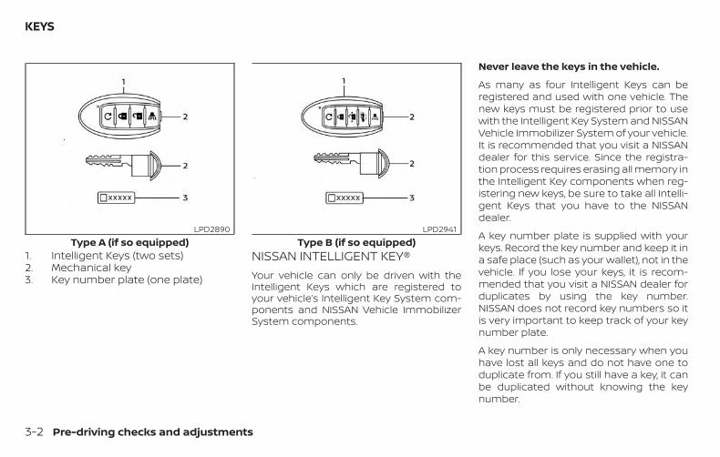
1. Intelligent Keys (two sets)2. Mechanical key3. Key number plate (one plate)
NISSAN INTELLIGENT KEY®Your vehicle can only be driven with theIntelligent Keys which are registered toyour vehicle’s Intelligent Key System com-ponents and NISSAN Vehicle ImmobilizerSystem components.
Never leave the keys in the vehicle.
As many as four Intelligent Keys can beregistered and used with one vehicle. Thenew keys must be registered prior to usewith the Intelligent Key System and NISSANVehicle Immobilizer System of your vehicle.It is recommended that you visit a NISSANdealer for this service. Since the registra-tion process requires erasing all memory inthe Intelligent Key components when reg-istering new keys, be sure to take all Intelli-gent Keys that you have to the NISSANdealer.
A key number plate is supplied with yourkeys. Record the key number and keep it ina safe place (such as your wallet), not in thevehicle. If you lose your keys, it is recom-mended that you visit a NISSAN dealer forduplicates by using the key number.NISSAN does not record key numbers so itis very important to keep track of your keynumber plate.
A key number is only necessary when youhave lost all keys and do not have one toduplicate from. If you still have a key, it canbe duplicated without knowing the keynumber.
Type A (if so equipped)LPD2890
Type B (if so equipped)LPD2941
KEYS
3-2 Pre-driving checks and adjustments
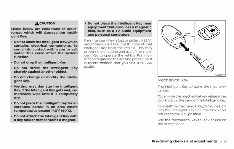
CAUTIONListed below are conditions or occur-rences which will damage the Intelli-gent Key:
∙ Do not allow the Intelligent Key, whichcontains electrical components, tocome into contact with water or saltwater. This could affect the systemfunction.
∙ Do not drop the Intelligent Key.
∙ Do not strike the Intelligent Keysharply against another object.
∙ Do not change or modify the Intelli-gent Key.
∙ Wetting may damage the IntelligentKey. If the Intelligent Key gets wet, im-mediately wipe until it is completelydry.
∙ Do not place the Intelligent Key for anextended period in an area wheretemperatures exceed 140°F (60°C).
∙ Do not attach the Intelligent Key witha key holder that contains a magnet.
∙ Do not place the Intelligent Key nearequipment that produces a magneticfield, such as a TV, audio equipmentand personal computers.
If an Intelligent Key is lost or stolen, NISSANrecommends erasing the ID code of thatIntelligent Key from the vehicle. This mayprevent the unauthorized use of the Intelli-gent Key to operate the vehicle. For infor-mation regarding the erasing procedure, itis recommended that you visit a NISSANdealer.
Mechanical keyThe Intelligent Key contains the mechani-cal key.
To remove the mechanical key, release thelock knob on the back of the Intelligent Key.
To install the mechanical key, firmly insert itinto the Intelligent Key until the lock knobreturns to the lock position.
Use the mechanical key to lock or unlockthe driver’s door.
SPA1951
Pre-driving checks and adjustments 3-3
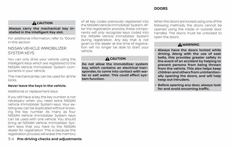
CAUTIONAlways carry the mechanical key in-stalled in the Intelligent Key slot.
For additional information, refer to “Doors”in this section.
NISSAN VEHICLE IMMOBILIZERSYSTEM KEYSYou can only drive your vehicle using theIntelligent Keys which are registered to theNISSAN Vehicle Immobilizer System com-ponents in your vehicle.
The mechanical key can be used for all thelocks.
Never leave the keys in the vehicle.
Additional or replacement keys:
If you still have a key, the key number is notnecessary when you need extra NISSANVehicle Immobilizer System keys. Your ex-isting key can be duplicated without know-ing the key number. As many as fourNISSAN Vehicle Immobilizer System keyscan be used with one vehicle. You shouldbring all NISSAN Vehicle Immobilizer Sys-tem keys that you have to the NISSANdealer for registration. This is because theregistration process will erase the memory
of all key codes previously registered intothe NISSAN Vehicle Immobilizer System. Af-ter the registration process, these compo-nents will only recognize keys coded intothe NISSAN Vehicle Immobilizer Systemduring registration. Any key that is notgiven to the dealer at the time of registra-tion will no longer be able to start yourvehicle.
CAUTIONDo not allow the immobilizer systemkey, which contains an electrical tran-sponder, to come into contact with wa-ter or salt water. This could affect sys-tem function.
When the doors are locked using one of thefollowing methods, the doors cannot beopened using the inside or outside doorhandles. The doors must be unlocked toopen the doors.
WARNING∙ Always have the doors locked while
driving. Along with the use of seatbelts, this provides greater safety inthe event of an accident by helping toprevent persons from being thrownfrom the vehicle. This also helps keepchildren and others from unintention-ally opening the doors, and will helpkeep out intruders.
∙ Before opening any door, always lookfor and avoid oncoming traffic.
DOORS
3-4 Pre-driving checks and adjustments
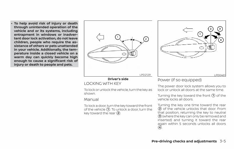
∙ To help avoid risk of injury or deaththrough unintended operation of thevehicle and or its systems, includingentrapment in windows or inadver-tent door lock activation, do not leavechildren, people who require the as-sistance of others or pets unattendedin your vehicle. Additionally, the tem-perature inside a closed vehicle on awarm day can quickly become highenough to cause a significant risk ofinjury or death to people and pets.
LOCKING WITH KEYTo lock or unlock the vehicle, turn the key asshown.
ManualTo lock a door, turn the key toward the frontof the vehicle �1 . To unlock a door, turn thekey toward the rear �2 .
Power (if so equipped)The power door lock system allows you tolock or unlock all doors at the same time.
Turning the key toward the front �1 of thevehicle locks all doors.
Turning the key one time toward the rear�2 of the vehicle unlocks that door. Fromthat position, returning the key to neutral�3 (where the key can only be removed andinserted) and turning it toward the rearagain within 5 seconds unlocks all doors�4 .
Driver’s sideLPD2129 LPD0461
Pre-driving checks and adjustments 3-5

LOCKING WITH INSIDE LOCK KNOBTo lock the door without the key, move theinside lock knob to the lock position �1 ,then close the door.
To unlock the door without the key, movethe inside lock knob to the unlock position�2 .
LOCKING WITH POWER DOORLOCK SWITCHTo lock all the doors without a key, push thedoor lock switch (driver’s or front passen-ger’s side) to the lock position �1 . Whenlocking the door this way, be certain not toleave the key inside the vehicle.
To unlock all the doors without a key, pushthe door lock switch (driver’s or front pas-senger’s side) to the unlock position �2 .
Lockout protectionWhen the power door lock switch is movedto the lock position with any door open andthe Intelligent Key is left in the vehicle, alldoors will unlock automatically and achime will sound after the door is closed.
This function helps to prevent the Intelli-gent Key from being accidentally lockedinside the vehicle.
AUTOMATIC DOOR LOCKS (if soequipped)
∙ All doors lock automatically when thevehicle speed reaches 15 mph(24 km/h).
∙ All doors unlock automatically when thetransmission is placed in the P (Park)position or when the ignition switch isplaced in the OFF position.
NOTE:
The automatic door unlock function canbe changed using the “Vehicle Settings”of the vehicle information display. Foradditional information, refer to “Vehicleinformation display” in the “Instrumentsand controls” section of this manual.
Inside lockSPA2726 LPD2309
3-6 Pre-driving checks and adjustments

CHILD SAFETY REAR DOOR LOCKChild safety locks help prevent the reardoors from being opened accidentally, es-pecially when small children are in the ve-hicle.
The child safety lock levers are located onthe edge of the rear doors.
When the lever is in the LOCK position,the door can be opened only from theoutside.
WARNING∙ Radio waves could adversely affect
electric medical equipment. Thosewho use a pacemaker should contactthe electric medical equipmentmanufacturer for the possible influ-ences before use.
∙ The Intelligent Key transmits radiowaves when the buttons are pressed.The FAA advises the radio waves mayaffect aircraft navigation and com-munication systems. Do not operatethe Intelligent Key while on an air-plane. Make sure the buttons are notoperated unintentionally when theunit is stored for a flight.
The Intelligent Key system can operate allthe door locks using the remote controlfunction or pushing the request switch onthe vehicle without taking the key out froma pocket or purse. The operating environ-ment and/or conditions may affect the In-telligent Key system operation.
Be sure to read the following before usingthe Intelligent Key system.
CAUTION∙ Be sure to carry the Intelligent Key
with you when operating the vehicle.
∙ Never leave the Intelligent Key in thevehicle when you leave the vehicle.
The Intelligent Key is always communicat-ing with the vehicle as it receives radiowaves. The Intelligent Key system trans-mits weak radio waves. Environmentalconditions may interfere with the opera-tion of the Intelligent Key system under thefollowing operating conditions:
∙ When operating near a location wherestrong radio waves are transmitted,such as a TV tower, power station andbroadcasting station.
∙ When in possession of wireless equip-ment, such as a cellular telephone,transceiver, or a CB radio.
∙ When the Intelligent Key is in contactwith or covered by metallic materials.
∙ When any type of radio wave remotecontrol is used nearby.
∙ When the Intelligent Key is placed nearan electric appliance such as a personalcomputer.
LPD2374
NISSAN INTELLIGENT KEY®
Pre-driving checks and adjustments 3-7

∙ When the vehicle is parked near a park-ing meter.
In such cases, correct the operating condi-tions before using the Intelligent Key func-tion or use the mechanical key.
Although the life of the battery varies de-pending on the operating conditions, thebattery’s life is approximately two years. Ifthe battery is discharged, replace it with anew one.
When the Intelligent Key battery is low, anindicator illuminates in the vehicle informa-tion display. For additional information, re-fer to “Vehicle information display” in the“Instruments and controls” section of thismanual.
Since the Intelligent Key is continuously re-ceiving radio waves, if the key is left nearequipment which transmits strong radiowaves, such as signals from a TV and per-sonal computer, the battery life may be-come shorter.
For additional information, refer to “Batteryreplacement” in the “Do-it-yourself ” sectionof this manual.
As many as four Intelligent Keys can beregistered and used with one vehicle. Forinformation about the purchase and use ofadditional Intelligent Keys, it is recom-mended that you visit a NISSAN dealer.
CAUTIONListed below are conditions or occur-rences which will damage the Intelli-gent Key:
∙ Do not allow the Intelligent Key, whichcontains electrical components, tocome into contact with water or saltwater. This could affect the systemfunction.
∙ Do not drop the Intelligent Key.
∙ Do not strike the Intelligent Keysharply against another object.
∙ Do not change or modify the Intelli-gent Key.
∙ Wetting may damage the IntelligentKey. If the Intelligent Key gets wet, im-mediately wipe until it is completelydry.
∙ Do not place the Intelligent Key for anextended period in an area wheretemperatures exceed 140°F (60°C).
∙ Do not attach the Intelligent Key witha key holder that contains a magnet.
∙ Do not place the Intelligent Key nearequipment that produces a magneticfield, such as a TV, audio equipmentand personal computers.
If an Intelligent Key is lost or stolen, NISSANrecommends erasing the ID code of thatIntelligent Key from the vehicle. This mayprevent the unauthorized use of the Intelli-gent Key to operate the vehicle. For infor-mation regarding the erasing procedure, itis recommended that you visit a NISSANdealer.
3-8 Pre-driving checks and adjustments

OPERATING RANGEThe Intelligent Key functions can only beused when the Intelligent Key is within thespecified operating range from the requestswitch �1 .
When the Intelligent Key battery is dis-charged or strong radio waves are presentnear the operating location, the IntelligentKey operating range becomes narrower,and the Intelligent Key may not functionproperly.
The operating range is within 31.5 in (80 cm)from each request switch �1 .
If the Intelligent Key is too close to the doorglass, handle or rear bumper, the requestswitches may not function.
When the Intelligent Key is within the oper-ating range, it is possible for anyone, evensomeone who does not carry the Intelli-gent Key, to push the request switch tolock/unlock the doors.
DOOR LOCKS/UNLOCKSPRECAUTION
∙ Do not push the door handle requestswitch with the Intelligent Key held inyour hand as illustrated. The close dis-tance to the door handle will cause theIntelligent Key system to have difficultyrecognizing that the Intelligent Key isoutside the vehicle.
∙ After locking with the door handle re-quest switch, verify the doors are se-curely locked by testing them.
LPD2653 LPD2554
Pre-driving checks and adjustments 3-9

∙ To prevent the Intelligent Key from be-ing left inside the vehicle, make sure youcarry the Intelligent Key with you andthen lock the doors.
∙ Do not pull the door handle beforepushing the door handle requestswitch. The door will be unlocked butwill not open. Release the door handleonce and pull it again to open the door.
NISSAN INTELLIGENT KEY®OPERATIONYou can lock or unlock the doors withouttaking the Intelligent Key out of your pocketor bag.
When you carry the Intelligent Key with you,you can lock or unlock all doors by pushingthe door handle request switch within therange of operation.
Locking doors1. Move the shift lever to the P (Park) posi-
tion, place the ignition switch in theLOCK position and make sure you carrythe Intelligent Key with you.
2. Close all doors.
3. Push any door handle request switchwhile carrying the Intelligent Key withyou.
4. All doors and the rear liftgate will lock.
LPD2181 LPD2893
3-10 Pre-driving checks and adjustments

5. The hazard indicator lights flash twiceand the outside buzzer sounds twice,unless the answer back feature is de-activated, then only the hazard lightswill flash. For additional information, re-fer to “Answer back horn feature” in thissection.
NOTE:
∙ Request switches for all doors andthe liftgate can be deactivated whenthe I-Key Door Lock setting is turnedoff in the Vehicle Settings of the ve-hicle information display. For addi-tional information, refer to “Vehicleinformation display” in the “Instru-ments and controls” section of thismanual.
∙ Doors lock with the door handle re-quest switch while the ignition switchis not in the LOCK position.
∙ Doors do not lock by pushing the doorhandle request switch while thatdoor is open. However, doors lockwith the mechanical key even if anydoor is open.
∙ Doors do not lock with the doorhandle request switch with the Intel-ligent Key inside the vehicle and abeep sounds to warn you. However,when an Intelligent Key is inside thevehicle, doors can be locked with an-other Intelligent Key.
CAUTION∙ After locking the doors using the re-
quest switch, make sure that thedoors have been securely locked byoperating the door handles or the rearliftgate opener switch.
∙ When locking the doors using the re-quest switch, make sure to have theIntelligent Key in your possession be-fore operating the request switch toprevent the Intelligent Key from beingleft in the vehicle.
∙ The request switch is operational onlywhen the Intelligent Key has been de-tected by the Intelligent Key system.
Lockout protection
To prevent the Intelligent Key from beingaccidentally locked in the vehicle, lockoutprotection is equipped with the IntelligentKey system.
When the driver’s side door is open, thedoors are locked, and then the IntelligentKey is put inside the vehicle and all thedoors are closed; the lock will automati-cally unlock and the warning chimesounds.
LPD2773
Pre-driving checks and adjustments 3-11
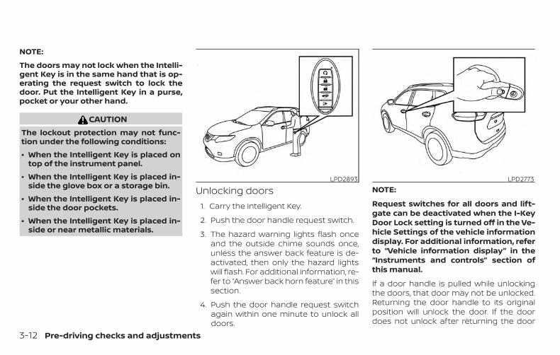
NOTE:
The doors may not lock when the Intelli-gent Key is in the same hand that is op-erating the request switch to lock thedoor. Put the Intelligent Key in a purse,pocket or your other hand.
CAUTIONThe lockout protection may not func-tion under the following conditions:
∙ When the Intelligent Key is placed ontop of the instrument panel.
∙ When the Intelligent Key is placed in-side the glove box or a storage bin.
∙ When the Intelligent Key is placed in-side the door pockets.
∙ When the Intelligent Key is placed in-side or near metallic materials.
Unlocking doors1. Carry the Intelligent Key.
2. Push the door handle request switch.
3. The hazard warning lights flash onceand the outside chime sounds once,unless the answer back feature is de-activated, then only the hazard lightswill flash. For additional information, re-fer to “Answer back horn feature” in thissection.
4. Push the door handle request switchagain within one minute to unlock alldoors.
NOTE:
Request switches for all doors and lift-gate can be deactivated when the I-KeyDoor Lock setting is turned off in the Ve-hicle Settings of the vehicle informationdisplay. For additional information, referto “Vehicle information display” in the“Instruments and controls” section ofthis manual.
If a door handle is pulled while unlockingthe doors, that door may not be unlocked.Returning the door handle to its originalposition will unlock the door. If the doordoes not unlock after returning the door
LPD2893 LPD2773
3-12 Pre-driving checks and adjustments

handle, push the door handle requestswitch to unlock the door.
All doors will be locked automatically un-less one of the following operations is per-formed within one minute after pushingthe request switch.
∙ Opening any door.
∙ Pushing the ignition switch.
The interior light timer illuminates for a pe-riod of time when a door is unlocked andthe room light switch is in the DOOR posi-tion.
The interior light can be turned off withoutwaiting by performing one of the followingoperations:
∙ Placing the ignition switch in the ON po-sition.
∙ Locking the doors with the remote con-trol.
∙ Switching the room light switch to theOFF position.
∙ Switching the Auto Room Lamp to theOFF position in Vehicle Settings of thevehicle information display. For addi-tional information, refer to “Vehicle in-formation display” in the “Instrumentsand controls” section.
HOW TO USE THE REMOTEKEYLESS ENTRY FUNCTIONThe remote keyless entry function can op-erate all door locks using the remote key-less function of the Intelligent Key. The re-mote keyless function can operate at adistance of 33 ft (10 m) away from the ve-hicle. The operating distance dependsupon the conditions around the vehicle.
The remote keyless entry function will notfunction under the following conditions:
∙ When the Intelligent Key is not within theoperational range.
∙ When the doors or the rear liftgate areopen or not closed securely.
∙ When the Intelligent Key battery is dis-charged.
CAUTIONWhen locking the doors using the Intel-ligent Key, be sure not to leave the key inthe vehicle.
Pre-driving checks and adjustments 3-13

Locking doors1. Place the ignition switch in the LOCK
position.
2. Close all doors.
3. Press the button on the Intelli-gent Key.
4. The hazard indicator lights flash twiceand the horn beeps once, unless theanswer back feature is deactivated,then only the hazard lights will flash.For additional information, refer to “An-swer back horn feature” in this section.
5. All doors will be locked.
CAUTIONAfter locking the doors using the Intel-ligent Key, be sure that the doors havebeen securely locked by operating thedoor handles.
Unlocking doors
1. Press the button on the IntelligentKey.
2. The driver’s door will unlock and thehazard indicator lights flash once.
3. Press the button again within60 seconds, the hazard indicator lightsflash once and the remaining doorsunlock.
LPD2876 LPD2877
3-14 Pre-driving checks and adjustments
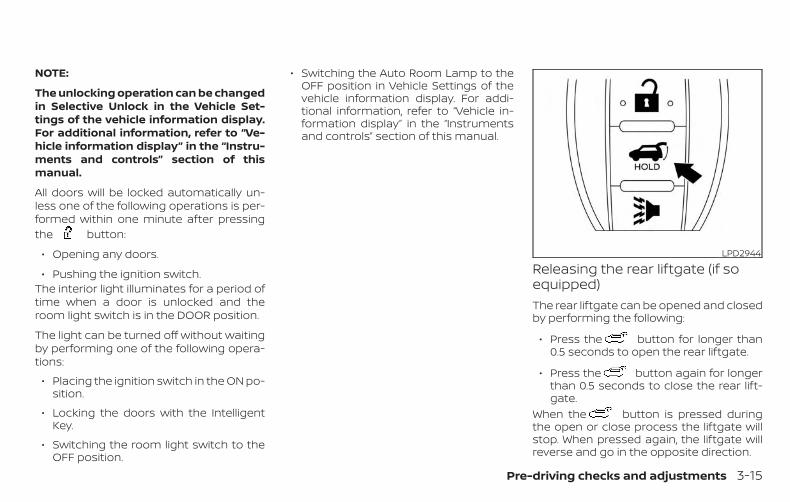
NOTE:
The unlocking operation can be changedin Selective Unlock in the Vehicle Set-tings of the vehicle information display.For additional information, refer to “Ve-hicle information display” in the “Instru-ments and controls” section of thismanual.
All doors will be locked automatically un-less one of the following operations is per-formed within one minute after pressingthe button:
∙ Opening any doors.
∙ Pushing the ignition switch.The interior light illuminates for a period oftime when a door is unlocked and theroom light switch is in the DOOR position.
The light can be turned off without waitingby performing one of the following opera-tions:
∙ Placing the ignition switch in the ON po-sition.
∙ Locking the doors with the IntelligentKey.
∙ Switching the room light switch to theOFF position.
∙ Switching the Auto Room Lamp to theOFF position in Vehicle Settings of thevehicle information display. For addi-tional information, refer to “Vehicle in-formation display” in the “Instrumentsand controls” section of this manual.
Releasing the rear liftgate (if soequipped)The rear liftgate can be opened and closedby performing the following:
∙ Press the button for longer than0.5 seconds to open the rear liftgate.
∙ Press the button again for longerthan 0.5 seconds to close the rear lift-gate.
When the button is pressed duringthe open or close process the liftgate willstop. When pressed again, the liftgate willreverse and go in the opposite direction.
LPD2944
Pre-driving checks and adjustments 3-15

Using the panic alarmIf you are near your vehicle and feel threat-ened, you may activate the panic alarm tocall attention by pressing and holdingthe button on the Intelligent Key forlonger than 0.5 seconds.The panic alarm and headlights will stay onfor a period of time.
The panic alarm stops when:
∙ It has run for a period of time, or
∙ Any button is pressed on the IntelligentKey.
∙ The request switch on the driver or pas-senger door is pushed and the Intelli-gent Key is in range of the door handle.
Using the interior lightsPress the button on the key fob onceto turn on the interior lights.For additional information, refer to “Interiorlights” in the “Instruments and controls”section of this manual. Answer back horn feature
If desired, the answer back horn featurecan be deactivated using the IntelligentKey. When it is deactivated and thebutton is pressed, the hazard indicatorlights flash twice. When the button ispressed, neither the hazard indicator lightsnor the horn operates.
LPD2945 LPD2837
3-16 Pre-driving checks and adjustments

NOTE:
If you change the answer back horn andlight flash feature with the IntelligentKey, the vehicle information displayscreen will show the current mode afterthe ignition switch has been cycled fromthe OFF to the ON position. The vehicleinformation display screen can also beused to change the answer back hornmode.To deactivate: Press and hold theand buttons for at least 2 seconds.The hazard indicator lights will flash threetimes to confirm that the answer backhorn feature has been deactivated.
To activate: Press and hold theand buttons for at least 2 secondsonce more.The hazard indicator lights will flash onceand the horn will sound once to confirmthat the horn beep feature has been reac-tivated.
Deactivating the horn beep feature doesnot silence the horn if the alarm is trig-gered.
Intelligent Key button operationlightThe light blinks only when you push anybutton on the Intelligent Key. The light illu-mination only signifies that the key fob hastransmitted a signal. You may look and/orlisten to verify that the vehicle has per-formed the intended operation. The num-ber of blinks identifies each registered key(i.e. 1 blink = 1st key,...,4 blinks = 4th key) foryour own identification purposes. If thelight does not blink, your battery may betoo weak to communicate to the vehicle. Ifthis occurs, the battery may need to bereplaced. For additional information re-
garding the replacement of a battery, referto “Battery replacement” in the “Do-it-yourself ” section of this manual.
WARNING SIGNALSTo help prevent the vehicle from movingunexpectedly by erroneous operation ofthe Intelligent Key or to help prevent thevehicle from being stolen, a chime orbuzzer sounds from inside and outside thevehicle and a warning is displayed in theinstrument panel.
When a chime or beep sounds or a warningis displayed, be sure to check the vehicleand the Intelligent Key.
For additional information, refer to the“Troubleshooting guide” in this section and“Vehicle information display” in the “Instru-ments and controls” section of this manual.
LPD2836
Pre-driving checks and adjustments 3-17
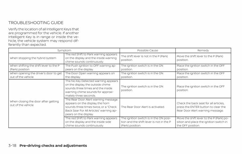
TROUBLESHOOTING GUIDEVerify the location of all Intelligent Keys thatare programmed for the vehicle. If anotherIntelligent Key is in range or inside the ve-hicle, the vehicle system may respond dif-ferently than expected.
Symptom Possible Cause Remedy
When stopping the hybrid systemThe red Shift to Park warning appearson the display and the inside warningchime sounds continuously.
The shift lever is not in the P (Park)position.
Move the shift lever to the P (Park)position.
When shifting the shift lever to the P(Park) position
The Push ignition to OFF warning ap-pears on the display.
The ignition switch is in the ONposition.
Place the ignition switch in the OFFposition.
When opening the driver’s door to getout of the vehicle
The Door Open warning appears onthe display.
The ignition switch is in the ONposition.
Place the ignition switch in the OFFposition.
When closing the door after gettingout of the vehicle
The No Key Detected warning appearson the display, the outside chimesounds three times and the insidewarning chime sounds for approxi-mately three seconds.
The ignition switch is in the ONposition.
Place the ignition switch in the OFFposition.
The Rear Door Alert warning messageappears on the display, the hornsounds three times twice, or a “CheckBack Sear For All Articles” warning ap-pears on the display.
The Rear Door Alert is activated.Check the back seat for all articles,press the ENTER button to clear theRear Door Alert warning message.
The red Shift to Park warning appearson the display and the inside sidechime sounds continuously.
The ignition switch is in the ON posi-tion and the shift lever is not in the P(Park) position.
Move the shift lever to the P (Park) po-sition and place the ignition switch inthe OFF position.
3-18 Pre-driving checks and adjustments

Symptom Possible Cause Remedy
When closing the door with the insidelock knob turned to LOCK
The outside chime sounds for approxi-mately three seconds and all thedoors unlock.
The Intelligent Key is inside the vehicle. Carry the Intelligent Key with you.
When pushing the door handle re-quest switch or the buttonon the Intelligent Key to lock the door
The outside chime sounds for approxi-mately three seconds. The Intelligent Key is inside the vehicle. Carry the Intelligent Key with you.
When pushing the ignition switch tostart the hybrid system
The Intelligent Key battery indicatorappears on the display. The battery charge is low.
Replace the battery with a new one.For additional information, refer to“Battery replacement” in the “Do-it-yourself ” section of this manual.
The yellow Key ID Incorrect warningappears on the display. The Intelligent Key is not in the vehicle. Carry the Intelligent Key with you.
When pushing the ignition switch The Key System Error warning ap-pears on the display.
It warns of a malfunction with the In-telligent Key system.
It is recommended that you visit aNISSAN dealer.
Pre-driving checks and adjustments 3-19

The button will be on the NISSAN In-telligent Key® if the vehicle has Remote Hy-brid Start. This feature allows the hybridsystem to start from outside the vehicle.The following features may be affectedwhen the remote start feature is used:
∙ Vehicles with automatic climate controlsystem will default to either heating orcooling mode depending on outsideand cabin temperatures. For additionalinformation, refer to “Remote HybridStart with Intelligent Climate Control” inthe “Monitor, climate, audio, phone andvoice recognition systems” section ofthis manual.
Laws in some local communities may re-strict the use of remote starters. For ex-ample, some laws require a person using
Remote Hybrid Start to have the vehicle inview. Check local regulations for any re-quirements.
Other conditions may affect the function ofthe Remote Hybrid Start feature. For addi-tional information, refer to “Conditions theRemote Hybrid Start will not work” in thissection.
Other conditions can affect the perfor-mance of the Intelligent Key transmitter.For additional information, refer to “NISSANIntelligent Key®” in this section.
REMOTE HYBRID STARTOPERATING RANGE
WARNINGTo help avoid risk of injury or deaththrough unintended operation of thevehicle and or its systems, including en-trapment in windows or inadvertentdoor lock activation, do not leave chil-dren, people who require the assistanceof others or pets unattended in your ve-hicle. Additionally, the temperature in-side a closed vehicle on a warm day canquickly become high enough to cause asignificant risk of injury or death topeople and pets.
Type A (if so equipped)LPD2895
Type B (if so equipped)LPD2947
REMOTE HYBRID START
3-20 Pre-driving checks and adjustments
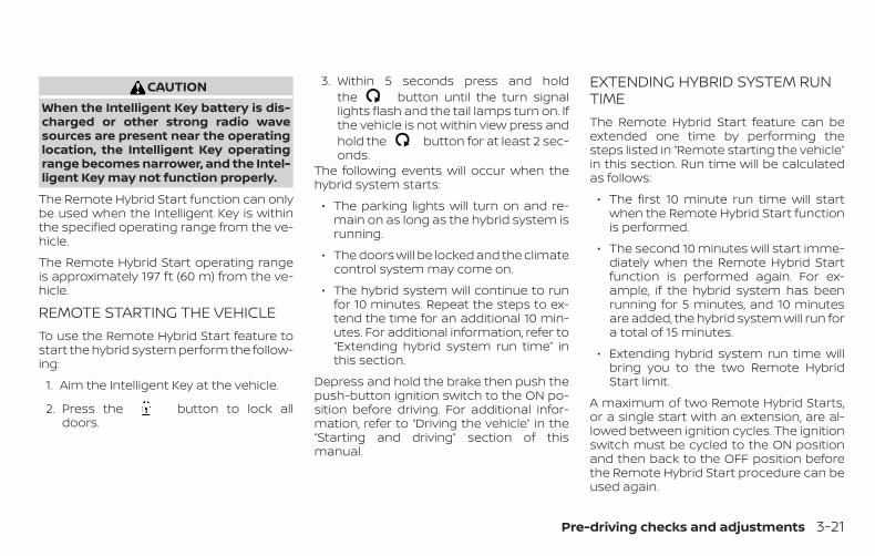
CAUTIONWhen the Intelligent Key battery is dis-charged or other strong radio wavesources are present near the operatinglocation, the Intelligent Key operatingrange becomes narrower, and the Intel-ligent Key may not function properly.
The Remote Hybrid Start function can onlybe used when the Intelligent Key is withinthe specified operating range from the ve-hicle.
The Remote Hybrid Start operating rangeis approximately 197 ft (60 m) from the ve-hicle.
REMOTE STARTING THE VEHICLETo use the Remote Hybrid Start feature tostart the hybrid system perform the follow-ing:
1. Aim the Intelligent Key at the vehicle.
2. Press the button to lock alldoors.
3. Within 5 seconds press and holdthe button until the turn signallights flash and the tail lamps turn on. Ifthe vehicle is not within view press andhold the button for at least 2 sec-onds.
The following events will occur when thehybrid system starts:
∙ The parking lights will turn on and re-main on as long as the hybrid system isrunning.
∙ The doors will be locked and the climatecontrol system may come on.
∙ The hybrid system will continue to runfor 10 minutes. Repeat the steps to ex-tend the time for an additional 10 min-utes. For additional information, refer to“Extending hybrid system run time” inthis section.
Depress and hold the brake then push thepush-button ignition switch to the ON po-sition before driving. For additional infor-mation, refer to “Driving the vehicle” in the“Starting and driving” section of thismanual.
EXTENDING HYBRID SYSTEM RUNTIMEThe Remote Hybrid Start feature can beextended one time by performing thesteps listed in “Remote starting the vehicle”in this section. Run time will be calculatedas follows:
∙ The first 10 minute run time will startwhen the Remote Hybrid Start functionis performed.
∙ The second 10 minutes will start imme-diately when the Remote Hybrid Startfunction is performed again. For ex-ample, if the hybrid system has beenrunning for 5 minutes, and 10 minutesare added, the hybrid system will run fora total of 15 minutes.
∙ Extending hybrid system run time willbring you to the two Remote HybridStart limit.
A maximum of two Remote Hybrid Starts,or a single start with an extension, are al-lowed between ignition cycles. The ignitionswitch must be cycled to the ON positionand then back to the OFF position beforethe Remote Hybrid Start procedure can beused again.
Pre-driving checks and adjustments 3-21

CANCELING A REMOTE HYBRIDSTARTTo cancel a Remote Hybrid Start, performone of the following:
∙ Aim the Intelligent Key at the vehicleand press until the parking lightsturn off.
∙ Turn on the hazard warning flashers.
∙ Cycle the ignition switch ON and thenOFF.
∙ The extended hybrid system run timehas expired.
∙ The first 10 minute timer has expired.
∙ The engine hood has been opened.
∙ The shift lever is moved out of park.
∙ The alarm sounds due to illegal entryinto the vehicle.
∙ The ignition switch is pushed withoutan Intelligent Key in the vehicle.
∙ The ignition switch is pushed with anIntelligent Key in the vehicle but thebrake pedal is not depressed.
CONDITIONS THE REMOTE HYBRIDSTART WILL NOT WORKThe Remote Hybrid Start will not operate ifany of the following conditions are present:
∙ The ignition switch is placed in the ONposition.
∙ The hood is not securely closed.
∙ The hazard indicator lights are on.
∙ The hybrid system is still running. Thehybrid system must be completelystopped. Wait at least 6 seconds if thehybrid system goes from running to off.This is not applicable when extendinghybrid system run time.
∙ The button is not pressed andheld for at least 2 seconds.
∙ The button is not pressed andheld within 5 seconds of pressing thelock button.
∙ The brake is pressed.
∙ The doors are not closed and locked.
∙ The liftgate is open.
∙ The I–Key Indicator Light remains solidin the vehicle information display.
∙ The alarm sounds due to illegal entryinto the vehicle.
∙ Two Remote Hybrid Starts, or a singleRemote Hybrid Start with an extension,have already been used.
∙ The vehicle is not in P (Park).
∙ There is a detected registered key al-ready inside of the vehicle.
∙ The Remote Start function has beenswitched to the OFF position in “VehicleSettings” of the vehicle information dis-play. For additional information, refer to“Vehicle information display” in the “In-struments and controls” section of thismanual.
The Remote Hybrid Start may display awarning or indicator in the vehicle informa-tion display. For additional information, re-fer to “Vehicle information display” in the“Instruments and controls” section of thismanual.
3-22 Pre-driving checks and adjustments

1. Pull the hood lock release handle �1located below the instrument paneluntil the hood springs up slightly.
2. Locate the lever �2 in between thehood and grille and push the lever side-ways with your fingertips.
3. Raise the hood �3 .
4. Remove the support rod �4 and insertit into the slot �5 .
Hold the coated parts �A when removingor resetting the support rod. Avoid directcontact with the metal parts, as theymay be hot immediately after the hybridsystem has been stopped.
When closing the hood, return the supportrod to its original position, lower the hoodto approximately 12 in (30 cm) above thelatch and release it. This allows proper en-gagement of the hood latch.
WARNING∙ Make sure the hood is completely
closed and latched before driving.Failure to do so could cause the hoodto fly open and result in an accident.
∙ If you see steam or smoke comingfrom the engine compartment, toavoid injury do not open the hood.
LPD2751
HOOD
Pre-driving checks and adjustments 3-23

WARNING∙ Always be sure the liftgate has been
closed securely to prevent it fromopening while driving.
∙ Do not drive with the liftgate open.This could allow dangerous exhaustgases to be drawn into the vehicle. Foradditional information, refer to “Ex-haust gas (carbon monoxide)” in the“Starting and driving” section of thismanual.
∙ To help avoid risk of injury or deaththrough unintended operation of thevehicle and or its systems, includingentrapment in windows or inadver-tent door lock activation, do not leavechildren, people who require the as-sistance of others or pets unattendedin your vehicle. Additionally, the tem-perature inside a closed vehicle on awarm day can quickly become highenough to cause a significant risk ofinjury or death to people and pets.
∙ Always be sure that hands and feetare clear of the door frame to avoidinjury while closing the liftgate.
CAUTIONDo not use accessory carriers that at-tach to the hatch. Doing so will causedamage to the vehicle.
OPERATING THE MANUALLIFTGATE (if so equipped)The power door lock system allows you tolock or unlock all doors including the lift-gate simultaneously.
To open the liftgate, push the liftgateopener switch �A and pull up on thehandle.
To close, lower and push the liftgate downsecurely.
LPD2655
LIFTGATE
3-24 Pre-driving checks and adjustments

OPERATING THE POWER LIFTGATE(if so equipped)
WARNING∙ Make sure that all passengers have
their hands, etc., inside the vehicle be-fore closing the liftgate.
∙ To help avoid risk of injury or deaththrough unintended operation of thevehicle and or its systems, includingentrapment in windows or inadver-tent door lock activation, do not leavechildren, people who require the as-sistance of others or pets unattendedin your vehicle. Additionally, the tem-perature inside a closed vehicle on awarm day can quickly become highenough to cause a significant risk ofinjury or death to people and pets.
NOTE:
To open, close or reverse the power lift-gate, the shift lever must be in P (Park).Also, the power liftgate will not operate ifbattery voltage is low.
Power Open:The power liftgate automatically movesfrom the fully closed position to the fullyopen position in approximately five – eightseconds. The power open feature can beactivated by the button on the key fob, theinstrument panel switch or the liftgate openswitch. A chime sounds to indicate thepower open sequence has been started.
LPD2900Instrument panel switch
LPD2212
Pre-driving checks and adjustments 3-25

∙ When the vehicle is locked, the liftgatecan be opened with the instrumentpanel switch or key fob.
∙ The key fob button must be held for0.5 second before the liftgate opens.
∙ The liftgate must be unlocked (or thekey fob must be within range) to openwith the liftgate open switch �A .
A warning chime will sound if the shift leveris moved out of P (Park) and the vehicle isbeginning to move, during a power openoperation.
Power Close:The power liftgate automatically movesfrom the fully open position to the second-ary position. When the liftgate reaches thesecondary position, the cinching motor en-gages and pulls the liftgate to its primarylatch position. Power close takes approxi-mately seven – ten seconds. The powerclose feature can be activated by the but-ton on the key fob, the instrument panelswitch or the liftgate close switch �B . Achime sounds to indicate the power closesequence has been started.
∙ If the liftgate open switch �A is acti-vated while the cinching motor is en-gaged, the cinching motor will disen-gage and release the latch.
∙ The key fob button must be held for0.5 second before the liftgate closes.
Stop - Reverse:During the open/close movement, the lift-gate can be stopped, if the Intelligent Key,instrument panel or liftgate switch (�A or�B ) is pressed. The liftgate can be reversedin the Intelligent Key, instrument panel orliftgate switch (�A or �B ) is pressed again.
Auto Reverse:If an obstacle is detected during poweropen or power close, a warning chime willsound and the liftgate will reverse directionand return to the full open or full close po-sition. If a second obstacle is detected, theliftgate motion will stop and the liftgate willenter manual mode.
A pinch strip is mounted on each side ofthe liftgate. If an obstacle is detected by apinch strip during power close, the liftgatewill reverse direction and return to the fullopen position.
Liftgate opener switchLCE2322 LPD2270
3-26 Pre-driving checks and adjustments
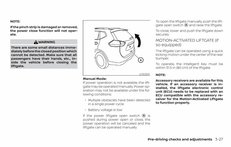
NOTE:
If the pinch strip is damaged or removed,the power close function will not oper-ate.
WARNINGThere are some small distances imme-diately before the closed position whichcannot be detected. Make sure that allpassengers have their hands, etc., in-side the vehicle before closing theliftgate.
Manual Mode:If power operation is not available, the lift-gate may be operated manually. Power op-eration may not be available under the fol-lowing conditions:
∙ Multiple obstacles have been detectedin a single power cycle
∙ Battery voltage is low
If the power liftgate open switch �A ispushed during power open or close, thepower operation will be canceled and theliftgate can be operated manually.
To open the liftgate manually, push the lift-gate open switch �A and raise the liftgate.
To close, lower and push the liftgate downsecurely.
MOTION-ACTIVATED LIFTGATE (ifso equipped)The liftgate can be operated using a quickkicking motion under the center of the rearbumper.
To operate, the Intelligent Key must bewithin 31.5 in (80 cm) of the liftgate.
NOTE:
Accessory receivers are available for thisvehicle. If an accessory receiver is in-stalled, the liftgate electronic controlunit (ECU) needs to be replaced with anECU compatible with the accessory re-ceiver for the Motion-Activated Liftgateto function properly.
LCE2321
Pre-driving checks and adjustments 3-27

Proper operation technique∙ While at the rear of the vehicle, begin
making a quick forward kicking motion.
∙ Raise your foot straight under the cen-ter of the rear bumper then immedi-ately return your foot to the ground in acontinuous motion.
∙ The kicking motion should be straight,smooth and consistent.
∙ After your kick motion is complete, stepback and allow the liftgate toopen/close.
∙ Three beeps will sound and the liftgatewill begin moving within two secondsafter the kick.
CAUTIONBefore performing the kicking motion,steady your stance to prevent any lossof balance. Also, while making the kick-ing motion, take caution around hot ex-haust system parts. Otherwise, theremay be danger of injury.
WARNINGPrevent unintentional liftgateopening/closing. There may be condi-tions when opening/closing the liftgateis not desired. Keep the Intelligent Keyout of range of the liftgate, (31.5 in or80 cm), when washing or workingaround the back of the vehicle.
Activation zoneLPD2762
DO: Quick forward kick and return whilethe key fob is within range
LPD2948DO NOT: Swing foot side to side or pause
during kick
LPD2764
3-28 Pre-driving checks and adjustments

CAUTION∙ Interference or malfunction can be
caused by parking in close proximityto radio or satellite towers.
∙ Intelligent Key interference could becaused if you have your key fob storednext to your cell phone or any RF-enabled smart card. For additional in-formation, refer to “NISSAN IntelligentKey®” in this section.
LIFTGATE RELEASE
WARNING∙ Always be sure the liftgate has been
closed securely to prevent it fromopening while driving.
∙ Do not drive with the liftgate open.This could allow dangerous exhaustgases to be drawn into the vehicle. Foradditional information, refer to “Ex-haust gas (carbon monoxide)” in the“Starting and driving” section of thismanual.
∙ To avoid personal injury, do not at-tempt to activate the power liftgate ifone or both of the liftgate struts areremoved.
CAUTION∙ If the power liftgate does not stay
open or if the liftgate unexpectedlycloses at any time while a continuouswarning chime sounds, do not oper-ate the liftgate. There may be a pres-sure loss in one or both of the liftgatestruts. It is recommended that youhave the liftgate inspected. It is rec-ommended that you visit a NISSANdealer for this service.
∙ Do not activate the power liftgate ifone or both of the liftgate struts areremoved. Damage to the liftgate orpower liftgate mechanisms mayoccur.
Manual liftgate release (if soequipped)The liftgate release mechanism allows theliftgate to be opened in the event of a dis-charged battery.
To release the liftgate from the inside of thevehicle, perform the following operations:
1. Fold the rear seats down. For additionalinformation, refer to “Folding the benchseat” in the “Safety—Seats, seat beltsand supplemental restraint system”section of this manual.
LPD2375
Pre-driving checks and adjustments 3-29

2. Insert a suitable tool in the lower ac-cess opening hole. Move the releaselever to the right. The liftgate will beunlatched.
3. Push the liftgate up to open.
NOTE:
If you had to open the liftgate using thislever, it is recommended that you haveyour vehicle checked as soon as pos-sible. It is recommended that you visit aNISSAN dealer for this service.
Power liftgate release (if soequipped)The liftgate release mechanism allows theliftgate to be opened in the event of a dis-charged battery.
To release the liftgate from the inside of thevehicle, perform the following operations:
1. Fold the rear seats down. For additionalinformation, refer to “Folding the benchseat” in the “Safety—Seats, seat beltsand supplemental restraint system”section of this manual.
2. Insert a suitable tool in the top accessopening hole. Move the release lever tothe right. The liftgate will be unlatched.
3. Push the liftgate up to open.
NOTE:
If you had to open the liftgate using thislever, it is recommended that you haveyour vehicle checked as soon as pos-sible. It is recommended that you visit aNISSAN dealer for this service.
LIFTGATE POSITION SETTINGThe liftgate can be set to open to a specificheight by performing the following:
1. Open the liftgate using the requestswitch or the Intelligent Key.
2. Pull the liftgate down to the desiredposition and hold the liftgate (the lift-gate will have some resistance whenbeing manually adjusted).
3. While holding the liftgate in position,push and hold the liftgate switchlocated on the liftgate for approxi-mately 5 seconds or until two beepsare heard.
LPD2949
3-30 Pre-driving checks and adjustments

The liftgate will open to the selected posi-tion setting. To change the position of theliftgate, repeat steps 1-3 for setting the po-sition of the liftgate.
OPENER OPERATIONThe fuel-filler door opener switch is locatedon the instrument panel. To open, push thefuel-filler opener switch.
To lock, close the fuel-filler door securely.
FUEL-FILLER CAP
WARNING∙ Gasoline is extremely flammable and
highly explosive under certain condi-tions. You could be burned or seri-ously injured if it is misused or mis-handled. Always stop the hybridsystem and do not smoke or allowopen flames or sparks near the ve-hicle when refueling
∙ Do not attempt to top off the fuel tankafter the fuel pump nozzle shuts offautomatically. Continued refuelingmay cause fuel overflow, resulting infuel spray and possibly a fire.
∙ Use only an original equipment typefuel-filler cap as a replacement. It hasa built-in safety valve needed forproper operation of the fuel systemand emission control system. An in-correct cap can result in a serious mal-function and possible injury. It couldalso cause the Malfunction Indi-cator Light (MIL) to come on.
∙ Never pour fuel into the throttle bodyto attempt to start your vehicle.
LPD2283
FUEL-FILLER DOOR
Pre-driving checks and adjustments 3-31
∙ Do not fill a portable fuel container inthe vehicle or trailer. Static electricitycan cause an explosion of flammableliquid, vapor or gas in any vehicle ortrailer. To reduce the risk of seriousinjury or death when filling portablefuel containers:
– Always place the container on theground when filling.
– Do not use electronic devices whenfilling.
– Keep the pump nozzle in contactwith the container while you arefilling it.
– Use only approved portable fuelcontainers for flammable liquid.
CAUTION∙ Do not use a fuel containing more
than 15% ethanol in your vehicle. Foradditional information, refer to “Fuelrecommendation” in the “Technicaland consumer information” section ofthis manual.
∙ The Loose Fuel Cap warning messagewill be displayed if the fuel-filler cap isnot properly tightened. It may take afew driving trips for the message tobe displayed. Failure to tighten thefuel-filler cap properly after the LooseFuel Cap warning message is dis-played may cause the Malfunc-tion Indicator Light (MIL) to illuminate.
∙ Failure to tighten the fuel-filler capproperly may cause the Mal-function Indicator Light (MIL) to illumi-nate. If the light illuminates be-cause the fuel-filler cap is loose ormissing, tighten or install the cap andcontinue to drive the vehicle.The light should turn off after afew driving trips. If the light doesnot turn off after a few driving trips,have the vehicle inspected. It is rec-ommended that you visit a NISSANdealer for this service.
∙ For additional information, refer to“Malfunction Indicator Light (MIL)” inthe “Instruments and controls” sec-tion of this manual.
∙ If fuel is spilled on the vehicle body,flush it away with water to avoid paintdamage.
3-32 Pre-driving checks and adjustments

To remove the fuel-filler cap:
1. Turn the fuel-filler cap counterclock-wise to remove.
2. Put the fuel-filler cap on the cap holder�1 while refueling.
To install the fuel-filler cap:
1. Insert the fuel-filler cap straight into thefuel-filler tube.
2. Turn the fuel-filler cap clockwise until asingle click is heard.
Loose Fuel Cap warningThe Loose Fuel Cap warning message willbe displayed in the vehicle information dis-play when the fuel-filler cap is not tight-ened correctly after the vehicle has beenrefueled. It may take a few driving trips forthe message to be displayed. To turn offthe warning message, perform the follow-ing:
1. Remove and install the fuel-filler cap assoon as possible. For additional infor-mation, refer to “Fuel-filler cap” in thissection.
2. Tighten the fuel-filler cap until a singleclick is heard.
3. Press the OK button �A on the steeringwheel for about one second to turn offthe Loose Fuel Cap warning message�B after tightening the fuel-filler cap.
LPD2186 LPD2659
Pre-driving checks and adjustments 3-33

WARNING∙ Do not adjust the steering wheel while
driving. You could lose control of yourvehicle and cause an accident.
∙ Do not adjust the steering wheel anycloser to you than is necessary forproper steering operation and com-fort. The driver’s air bag inflates withgreat force. If you are unrestrained,leaning forward, sitting sideways orout of position in any way, you are atgreater risk of injury or death in acrash. You may also receive serious orfatal injuries from the air bag if youare up against it when it inflates. Al-ways sit back against the seatbackand as far away as practical from thesteering wheel. Always use the seatbelts.
MANUAL OPERATIONTilt and telescopic operationPull the lock lever �1 down:
∙ Adjust the steering wheel up or down indirection �2 to the desired position.
∙ Adjust the steering wheel forward orbackward in direction �3 to the desiredposition.
Push the lock lever �1 up firmly to lock thesteering wheel in place.
LPD2648
WPD0344
STEERING WHEEL SUN VISORS
3-34 Pre-driving checks and adjustments
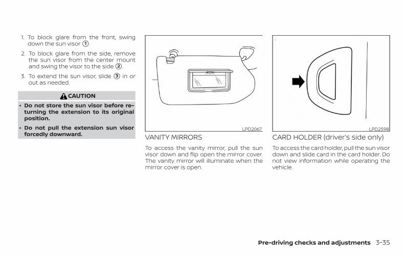
1. To block glare from the front, swingdown the sun visor �1 .
2. To block glare from the side, removethe sun visor from the center mountand swing the visor to the side �2 .
3. To extend the sun visor, slide �3 in orout as needed.
CAUTION∙ Do not store the sun visor before re-
turning the extension to its originalposition.
∙ Do not pull the extension sun visorforcedly downward. VANITY MIRRORS
To access the vanity mirror, pull the sunvisor down and flip open the mirror cover.The vanity mirror will illuminate when themirror cover is open.
CARD HOLDER (driver’s side only)To access the card holder, pull the sun visordown and slide card in the card holder. Donot view information while operating thevehicle.
LPD2067 LPD2598
Pre-driving checks and adjustments 3-35

MANUAL ANTI-GLARE REARVIEWMIRROR (if so equipped)Use the night position �1 to reduce glarefrom the headlights of vehicles behind youat night.
Use the day position �2 when driving indaylight hours.
WARNINGUse the night position only when neces-sary, because it reduces rear viewclarity.
AUTOMATIC ANTI-GLAREREARVIEW MIRROR (if so equipped)The inside mirror is designed so that it au-tomatically dims during night time condi-tions and according to the intensity of theheadlights of the vehicle following you. Theautomatic anti-glare feature is activatedwhen the ignition switch is in the ON posi-tion.
NOTE:
Do not hang any objects over the sen-sors �1 or apply glass cleaner to the sen-sors. Doing so will reduce the sensitivityof the sensors, resulting in improper op-eration. Type A (if so equipped)
The inside mirror is designed so that it au-tomatically dims during night time condi-tions and according to the intensity of theheadlights of the vehicle following you. Theautomatic anti-glare feature is activatedwhen the ignition switch is in the ON posi-tion.
WPD0126Type A (if so equipped)
LPD2418
MIRRORS
3-36 Pre-driving checks and adjustments
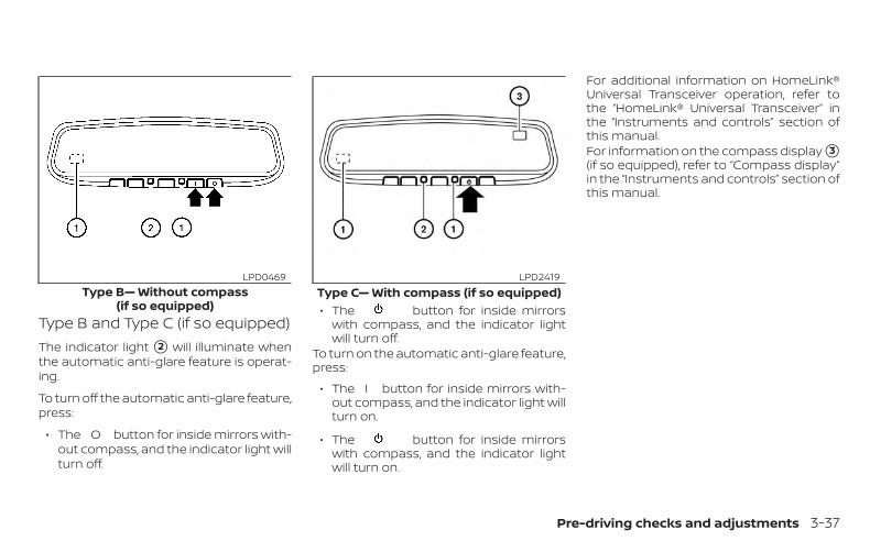
Type B and Type C (if so equipped)The indicator light �2 will illuminate whenthe automatic anti-glare feature is operat-ing.
To turn off the automatic anti-glare feature,press:
∙ The O button for inside mirrors with-out compass, and the indicator light willturn off.
∙ The button for inside mirrorswith compass, and the indicator lightwill turn off.
To turn on the automatic anti-glare feature,press:
∙ The I button for inside mirrors with-out compass, and the indicator light willturn on.
∙ The button for inside mirrorswith compass, and the indicator lightwill turn on.
For additional information on HomeLink®Universal Transceiver operation, refer tothe “HomeLink® Universal Transceiver” inthe “Instruments and controls” section ofthis manual.For information on the compass display �3(if so equipped), refer to “Compass display”in the “Instruments and controls” section ofthis manual.
Type B— Without compass(if so equipped)
LPD0469Type C— With compass (if so equipped)
LPD2419
Pre-driving checks and adjustments 3-37

OUTSIDE MIRRORSThe outside mirror remote control will op-erate only when the ignition switch is in theON position.
Move the small switch �1 to select the leftor right mirror. Adjust each mirror to thedesired position using the large switch �2 .Move the switch �1 to the center (neutral)position to prevent accidentally movingthe mirror.
WARNING∙ Objects viewed in the outside mirror
on the passenger side are closer thanthey appear. Be careful when movingto the right. Using only this mirrorcould cause an accident. Use the in-side mirror or glance over your shoul-der to properly judge distances toother objects.
∙ Do not adjust the mirrors while driv-ing. You could lose control of your ve-hicle and cause an accident.
Manual folding outside mirrorsPull the outside mirror toward the door tofold it.
Reverse tilt-down feature (if soequipped)The reverse tilt-down feature will turn bothoutside mirror surfaces downward to pro-vide better rear visibility close to the vehiclewhen the mirror control switch is in eitherthe L or R position.
The mirrors automatically return to theiroriginal position when you shift out of R(Reverse).
LPD2452 LPD2084
3-38 Pre-driving checks and adjustments

The outside mirror surfaces will return totheir original position when one of the fol-lowing conditions has occurred:
∙ The shift lever is moved to any positionother than R (Reverse).
∙ The outside mirror control switch is setto the neutral or center position.
∙ The ignition switch is placed in the OFFposition.
NOTE:
If the outside mirror control switch is inthe “center” position, the mirror surfacewill NOT turn downward when the shiftlever is moved to R (Reverse).
For additional information, refer to “Auto-matic drive positioner” in this section.
Heated mirrors (if so equipped)Some outside mirrors can be heated todefrost, defog, or de-ice for improved vis-ibility. For additional information, refer to“Rear window and outside mirror (if soequipped) defroster switch” in the “Instru-ments and controls” section of this manual.
The automatic drive positioner system hastwo features:
∙ Memory storage function
∙ Entry/exit function
MEMORY STORAGE FUNCTIONTwo positions for the driver’s seat and out-side mirrors can be stored in the automaticdrive positioner memory. Follow these pro-cedures to use the memory system.
1. Place the ignition in the ON or OFF po-sition (the vehicle should be stoppedwhile setting the memory).
2. Adjust the driver’s seat and outsidemirrors to the desired positions bymanually operating each adjustingswitch. For additional information, referto “Seats” in the “Safety—Seats, seatbelts and supplemental restraint sys-tem” section of this manual and “Out-side mirrors” in this section.
LPD2531
AUTOMATIC DRIVE POSITIONER (if soequipped)
Pre-driving checks and adjustments 3-39

3. Push the SET switch and, within 5 sec-onds, push the memory switch (1 or 2).
4. The indicator light for the pushedmemory switch will come on and stayon for approximately 5 seconds.
5. The chime will sound if the memoryhas been stored.
NOTE:
If a new memory position is stored in thesame memory switch, the previousmemory position will be overwritten bythe new stored position.
Confirming memory storage∙ Push the SET switch.
∙ If a memory position has not beenstored in the switch (1 or 2) the indicatorlight for the respective switch will comeON for approximately 0.5 seconds.
∙ If a memory position has been stored inthe switch (1 or 2) then the indicator lightfor the respective switch will stay ON forapproximately 5 seconds.
Linking a key fob to a storedmemory positionEach key fob can be linked to a storedmemory position (memory switch 1 or 2)with the following procedure.
1. Follow steps 1-3 in the “Memory storagefunction” section for storing thememory position.
2. The indicator light for the pushedmemory switch will come on. While theindicator light is on for 5 seconds, pressthe button on the key fob. Theindicator light of the linked memoryswitch will blink. After the indicator lightgoes off, the key fob is linked to thatmemory setting.
Once it is linked, when ignition switch isplaced in the OFF position, pressingthe button on the key fob will movethe driver’s seat and outside mirrors to thelinked memory switch position.
NOTE:
If a new memory position is stored in thelinked memory switch, then the key fobwill link the new position and overwritesthe previous position.
ENTRY/EXIT FUNCTIONThis system is designed so that the driver’sseat will automatically move when the shiftlever is in the P (Park) position. This allowsthe driver to get into and out of the driver’sseat more easily.
The driver’s seat will slide backward:
∙ When the driver’s door is opened withthe ignition switch placed in the OFFposition.
∙ When the ignition switch is changedfrom ON to OFF with the driver’s dooropen.
The driver’s seat will return to the previousposition:
∙ When the ignition switch is turned to ONwhile the shift lever is in the P (Park)position.
3-40 Pre-driving checks and adjustments
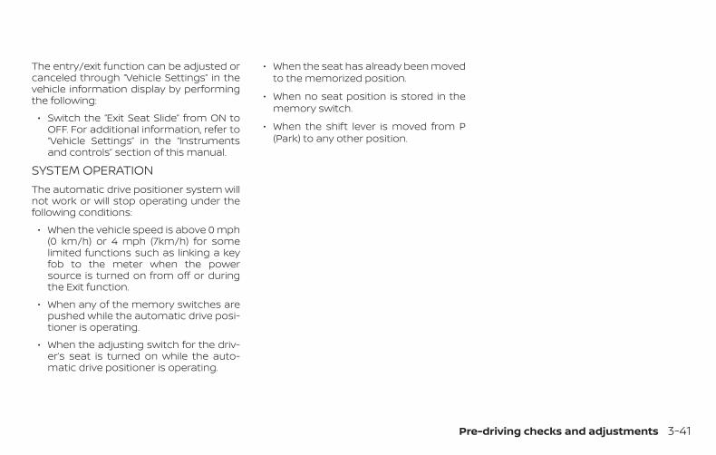
The entry/exit function can be adjusted orcanceled through “Vehicle Settings” in thevehicle information display by performingthe following:
∙ Switch the “Exit Seat Slide” from ON toOFF. For additional information, refer to“Vehicle Settings” in the “Instrumentsand controls” section of this manual.
SYSTEM OPERATIONThe automatic drive positioner system willnot work or will stop operating under thefollowing conditions:
∙ When the vehicle speed is above 0 mph(0 km/h) or 4 mph (7km/h) for somelimited functions such as linking a keyfob to the meter when the powersource is turned on from off or duringthe Exit function.
∙ When any of the memory switches arepushed while the automatic drive posi-tioner is operating.
∙ When the adjusting switch for the driv-er’s seat is turned on while the auto-matic drive positioner is operating.
∙ When the seat has already been movedto the memorized position.
∙ When no seat position is stored in thememory switch.
∙ When the shift lever is moved from P(Park) to any other position.
Pre-driving checks and adjustments 3-41

MEMO
3-42 Pre-driving checks and adjustments

4 Monitor, climate, audio, phone andvoice recognition systems
NissanConnect® Owner’s Manual . . . . . . . . . . . . . . . . 4-2RearView Monitor (if so equipped) . . . . . . . . . . . . . . . 4-3
RearView Monitor system operation . . . . . . . . . . 4-4How to read the displayed lines. . . . . . . . . . . . . . . 4-5Difference between predicted andactual distances. . . . . . . . . . . . . . . . . . . . . . . . . . . . . . 4-5How to park with predicted courselines . . . . . . . . . . . . . . . . . . . . . . . . . . . . . . . . . . . . . . . . . . 4-7Adjusting the screen . . . . . . . . . . . . . . . . . . . . . . . . . 4-9How to turn on and off predictedcourse lines . . . . . . . . . . . . . . . . . . . . . . . . . . . . . . . . . . 4-9RearView Monitor system limitations . . . . . . . . . 4-9System maintenance. . . . . . . . . . . . . . . . . . . . . . . . 4-10
Intelligent Around View Monitor(if so equipped) . . . . . . . . . . . . . . . . . . . . . . . . . . . . . . . . . .4-11
Intelligent Around View Monitor systemoperation. . . . . . . . . . . . . . . . . . . . . . . . . . . . . . . . . . . . 4-12Difference between predicted andactual distances. . . . . . . . . . . . . . . . . . . . . . . . . . . . . 4-16How to park with predicted courselines . . . . . . . . . . . . . . . . . . . . . . . . . . . . . . . . . . . . . . . . . 4-18
How to switch the display . . . . . . . . . . . . . . . . . . . 4-19Adjusting the screen . . . . . . . . . . . . . . . . . . . . . . . . 4-20Intelligent Around View Monitor systemlimitations . . . . . . . . . . . . . . . . . . . . . . . . . . . . . . . . . . . 4-21System maintenance. . . . . . . . . . . . . . . . . . . . . . . . 4-23
Moving Object Detection (MOD)(if so equipped) . . . . . . . . . . . . . . . . . . . . . . . . . . . . . . . . . 4-24
MOD system operation . . . . . . . . . . . . . . . . . . . . . . 4-25Turning MOD on and off (if so equipped) . . . . . 4-27MOD system limitations . . . . . . . . . . . . . . . . . . . . . 4-27System maintenance. . . . . . . . . . . . . . . . . . . . . . . . 4-28
Vents. . . . . . . . . . . . . . . . . . . . . . . . . . . . . . . . . . . . . . . . . . . 4-29Heater and air conditioner (automatic) . . . . . . . . . 4-30
Automatic operation . . . . . . . . . . . . . . . . . . . . . . . . 4-31Manual operation . . . . . . . . . . . . . . . . . . . . . . . . . . . 4-32Operating tips . . . . . . . . . . . . . . . . . . . . . . . . . . . . . . . 4-33
Servicing air conditioner . . . . . . . . . . . . . . . . . . . . . . . . 4-34USB/iPod® Charging Port . . . . . . . . . . . . . . . . . . . . . . . 4-35Antenna. . . . . . . . . . . . . . . . . . . . . . . . . . . . . . . . . . . . . . . . 4-35Car phone or CB radio . . . . . . . . . . . . . . . . . . . . . . . . . . 4-35
Refer to the NissanConnect® Owner’sManual that includes the following infor-mation.
∙ NissanConnect® Services (if soequipped)
∙ Navigation system (if so equipped)
∙ Audio system
∙ Apple CarPlayTM
∙ Android AutoTM
∙ Bluetooth® Hands-Free Phone system
∙ Viewing information
∙ Other settings
∙ Voice recognition
∙ General system information
NISSANCONNECT® OWNER’SMANUAL
4-2 Monitor, climate, audio, phone and voice recognition systems

1. CAMERA buttonLHA4694
REARVIEW MONITOR (if soequipped)
Monitor, climate, audio, phone and voice recognition systems 4-3

WARNINGFailure to follow the warnings and in-structions for proper use of the Rear-View Monitor system could result in se-rious injury or death.
∙ RearView Monitor is a conveniencefeature and is not a substitute forproper backing. Always turn and lookout the windows and check mirrors tobe sure that it is safe to move beforeoperating the vehicle. Always back upslowly.
∙ The system is designed as an aid tothe driver in showing large stationaryobjects directly behind the vehicle, tohelp avoid damaging the vehicle.
∙ The distance guide line and the ve-hicle width line should be used as areference only when the vehicle is on alevel paved surface. The distanceviewed on the monitor is for referenceonly and may be different than theactual distance between the vehicleand displayed objects.
CAUTIONDo not scratch the camera lens whencleaning dirt or snow from the front ofthe camera.
The RearView Monitor system automati-cally shows a rear view of the vehicle whenthe shift lever is shifted into the R (Reverse)position. While in R (Reverse), pressing theCAMERA button will cycle through guide-line options. The radio can still be heardwhile the RearView Monitor is active.
To display the rear view, the RearView Moni-tor system uses a camera located justabove the vehicle’s license plate �1 .
REARVIEW MONITOR SYSTEMOPERATIONWith the ignition switch in the ON position,move the shift lever to the R (Reverse) po-sition to operate the RearView Monitor.
LHA3694
4-4 Monitor, climate, audio, phone and voice recognition systems
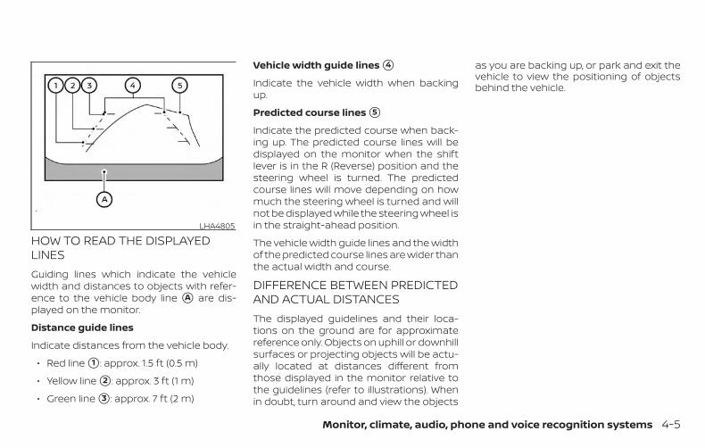
HOW TO READ THE DISPLAYEDLINESGuiding lines which indicate the vehiclewidth and distances to objects with refer-ence to the vehicle body line �A are dis-played on the monitor.
Distance guide lines
Indicate distances from the vehicle body.
∙ Red line �1 : approx. 1.5 ft (0.5 m)
∙ Yellow line �2 : approx. 3 ft (1 m)
∙ Green line �3 : approx. 7 ft (2 m)
Vehicle width guide lines �4
Indicate the vehicle width when backingup.
Predicted course lines �5
Indicate the predicted course when back-ing up. The predicted course lines will bedisplayed on the monitor when the shiftlever is in the R (Reverse) position and thesteering wheel is turned. The predictedcourse lines will move depending on howmuch the steering wheel is turned and willnot be displayed while the steering wheel isin the straight-ahead position.
The vehicle width guide lines and the widthof the predicted course lines are wider thanthe actual width and course.
DIFFERENCE BETWEEN PREDICTEDAND ACTUAL DISTANCESThe displayed guidelines and their loca-tions on the ground are for approximatereference only. Objects on uphill or downhillsurfaces or projecting objects will be actu-ally located at distances different fromthose displayed in the monitor relative tothe guidelines (refer to illustrations). Whenin doubt, turn around and view the objects
as you are backing up, or park and exit thevehicle to view the positioning of objectsbehind the vehicle.
LHA4805
Monitor, climate, audio, phone and voice recognition systems 4-5

Backing up on a steep uphillWhen backing up the vehicle up a hill, thedistance guide lines and the vehicle widthguide lines are shown closer than the actualdistance. Note that any object on the hill isfurther than it appears on the monitor.
Backing up on a steep downhillWhen backing up the vehicle down a hill, thedistance guide lines and the vehicle widthguide lines are shown farther than the actualdistance. Note that any object on the hill iscloser than it appears on the monitor.
Backing up near a projectingobjectThe predicted course lines �A do not touchthe object in the display. However, the ve-hicle may hit the object if it projects overthe actual backing up course.
LHA4993 LHA4994 LHA4995
4-6 Monitor, climate, audio, phone and voice recognition systems
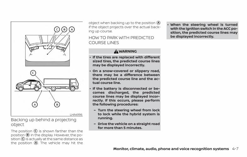
Backing up behind a projectingobjectThe position �C is shown farther than theposition �B in the display. However, the po-sition �C is actually at the same distance asthe position �A . The vehicle may hit the
object when backing up to the position �Aif the object projects over the actual back-ing up course.
HOW TO PARK WITH PREDICTEDCOURSE LINES
WARNING∙ If the tires are replaced with different
sized tires, the predicted course linesmay be displayed incorrectly.
∙ On a snow-covered or slippery road,there may be a difference betweenthe predicted course line and the ac-tual course line.
∙ If the battery is disconnected or be-comes discharged, the predictedcourse lines may be displayed incor-rectly. If this occurs, please performthe following procedures:
– Turn the steering wheel from lockto lock while the hybrid system isrunning.
– Drive the vehicle on a straight roadfor more than 5 minutes.
∙ When the steering wheel is turnedwith the ignition switch in the ACC po-sition, the predicted course lines maybe displayed incorrectly.
LHA4996
Monitor, climate, audio, phone and voice recognition systems 4-7
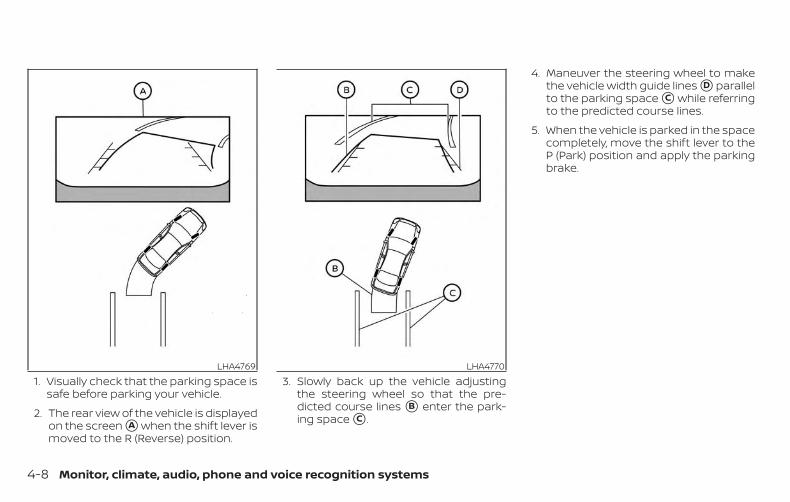
1. Visually check that the parking space issafe before parking your vehicle.
2. The rear view of the vehicle is displayedon the screen �A when the shift lever ismoved to the R (Reverse) position.
3. Slowly back up the vehicle adjustingthe steering wheel so that the pre-dicted course lines �B enter the park-ing space �C .
4. Maneuver the steering wheel to makethe vehicle width guide lines �D parallelto the parking space �C while referringto the predicted course lines.
5. When the vehicle is parked in the spacecompletely, move the shift lever to theP (Park) position and apply the parkingbrake.
LHA4769 LHA4770
4-8 Monitor, climate, audio, phone and voice recognition systems
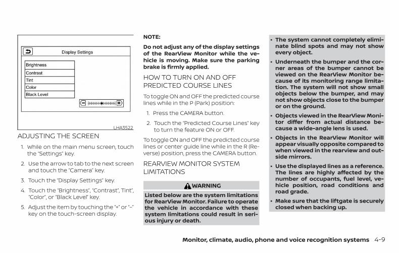
ADJUSTING THE SCREEN1. While on the main menu screen, touch
the “Settings” key.
2. Use the arrow to tab to the next screenand touch the “Camera” key.
3. Touch the “Display Settings” key.
4. Touch the “Brightness”, “Contrast”, Tint”,“Color”, or “Black Level” key.
5. Adjust the item by touching the “+” or “–”key on the touch-screen display.
NOTE:
Do not adjust any of the display settingsof the RearView Monitor while the ve-hicle is moving. Make sure the parkingbrake is firmly applied.
HOW TO TURN ON AND OFFPREDICTED COURSE LINESTo toggle ON and OFF the predicted courselines while in the P (Park) position:
1. Press the CAMERA button.
2. Touch the “Predicted Course Lines” keyto turn the feature ON or OFF.
To toggle ON and OFF the predicted courselines or center guide line while in the R (Re-verse) position, press the CAMERA button.
REARVIEW MONITOR SYSTEMLIMITATIONS
WARNINGListed below are the system limitationsfor RearView Monitor. Failure to operatethe vehicle in accordance with thesesystem limitations could result in seri-ous injury or death.
∙ The system cannot completely elimi-nate blind spots and may not showevery object.
∙ Underneath the bumper and the cor-ner areas of the bumper cannot beviewed on the RearView Monitor be-cause of its monitoring range limita-tion. The system will not show smallobjects below the bumper, and maynot show objects close to the bumperor on the ground.
∙ Objects viewed in the RearView Moni-tor differ from actual distance be-cause a wide-angle lens is used.
∙ Objects in the RearView Monitor willappear visually opposite compared towhen viewed in the rearview and out-side mirrors.
∙ Use the displayed lines as a reference.The lines are highly affected by thenumber of occupants, fuel level, ve-hicle position, road conditions androad grade.
∙ Make sure that the liftgate is securelyclosed when backing up.
LHA3522
Monitor, climate, audio, phone and voice recognition systems 4-9
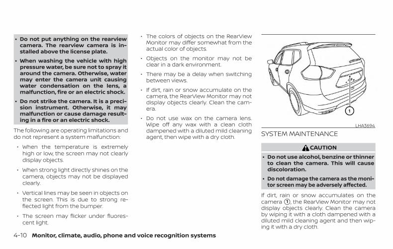
∙ Do not put anything on the rearviewcamera. The rearview camera is in-stalled above the license plate.
∙ When washing the vehicle with highpressure water, be sure not to spray itaround the camera. Otherwise, watermay enter the camera unit causingwater condensation on the lens, amalfunction, fire or an electric shock.
∙ Do not strike the camera. It is a preci-sion instrument. Otherwise, it maymalfunction or cause damage result-ing in a fire or an electric shock.
The following are operating limitations anddo not represent a system malfunction:
∙ When the temperature is extremelyhigh or low, the screen may not clearlydisplay objects.
∙ When strong light directly shines on thecamera, objects may not be displayedclearly.
∙ Vertical lines may be seen in objects onthe screen. This is due to strong re-flected light from the bumper.
∙ The screen may flicker under fluores-cent light.
∙ The colors of objects on the RearViewMonitor may differ somewhat from theactual color of objects.
∙ Objects on the monitor may not beclear in a dark environment.
∙ There may be a delay when switchingbetween views.
∙ If dirt, rain or snow accumulate on thecamera, the RearView Monitor may notdisplay objects clearly. Clean the cam-era.
∙ Do not use wax on the camera lens.Wipe off any wax with a clean clothdampened with a diluted mild cleaningagent, then wipe with a dry cloth. SYSTEM MAINTENANCE
CAUTION∙ Do not use alcohol, benzine or thinner
to clean the camera. This will causediscoloration.
∙ Do not damage the camera as the moni-tor screen may be adversely affected.
If dirt, rain or snow accumulates on thecamera �1 , the RearView Monitor may notdisplay objects clearly. Clean the cameraby wiping it with a cloth dampened with adiluted mild cleaning agent and then wip-ing it with a dry cloth.
LHA3694
4-10 Monitor, climate, audio, phone and voice recognition systems

1. CAMERA buttonLHA4694
INTELLIGENT AROUND VIEWMONITOR (if so equipped)
Monitor, climate, audio, phone and voice recognition systems 4-11
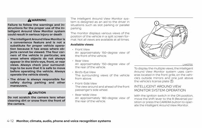
WARNINGFailure to follow the warnings and in-structions for the proper use of the In-telligent Around View Monitor systemcould result in serious injury or death
∙ The Intelligent Around View Monitor isa convenience feature and is not asubstitute for proper vehicle opera-tion because it has areas where ob-jects cannot be viewed. The four cor-ners of the vehicle in particular, areareas where objects do not alwaysappear in the bird’s-eye, front, or rearviews. Always check your surround-ings to be sure that it is safe to movebefore operating the vehicle. Alwaysoperate the vehicle slowly.
∙ The driver is always responsible forsafety during parking and othermaneuvers.
CAUTIONDo not scratch the camera lens whencleaning dirt or snow from the front ofthe camera.
The Intelligent Around View Monitor sys-tem is designed as an aid to the driver insituations such as slot parking or parallelparking.
The monitor displays various views of theposition of the vehicle in a split screen for-mat. Not all views are available at all times.
Available views:
∙ Front ViewAn approximately 150–degree view ofthe front of the vehicle.
∙ Rear ViewAn approximately 150–degree view ofthe rear of the vehicle.
∙ Bird’s-Eye ViewThe surrounding views of the vehiclefrom above.
∙ Front-Side ViewThe view around and ahead of the frontpassenger’s side wheel.
∙ Rear-Wide ViewAn approximately 180–degree view ofthe rear of the vehicle.
To display the multiple views, the IntelligentAround View Monitor system uses cam-eras located in the front grille, on the vehi-cle’s outside mirrors and one just abovethe vehicle’s license plate �1 .
INTELLIGENT AROUND VIEWMONITOR SYSTEM OPERATIONWith the ignition switch in the ON position,move the shift lever to the R (Reverse) po-sition or press the CAMERA button to oper-ate the Intelligent Around View Monitor.
LHA3700
4-12 Monitor, climate, audio, phone and voice recognition systems

The screen displayed on the IntelligentAround View Monitor will automatically re-turn to the previous screen 3 minutes afterthe CAMERA button has been pressed withthe shift lever in a position other than the R(Reverse) position.
Available views
WARNING∙ The distance guide lines and the ve-
hicle width lines should be used as areference only when the vehicle is on apaved, level surface. The apparentdistance viewed on the monitor maybe different than the actual distancebetween the vehicle and displayedobjects.
∙ Use the displayed lines and the bird’s-eye view as a reference. The lines andthe bird’s-eye view are greatly af-fected by the number of occupants,cargo, fuel level, vehicle position, roadcondition and road grade.
∙ If the tires are replaced with differentsized tires, the predicted course linesand the bird’s-eye view may be dis-played incorrectly.
∙ When driving the vehicle up a hill, ob-jects viewed in the monitor are fur-ther than they appear. When drivingthe vehicle down a hill, objects viewedin the monitor are closer than theyappear.
∙ Objects in the rear view will appearvisually opposite compared to whenviewed in the monitor and outsidemirrors.
∙ Use the mirrors or actually look toproperly judge distances to otherobjects.
∙ On a snow-covered or slippery road,there may be a difference betweenthe predicted course lines and the ac-tual course line.
∙ The vehicle width and predictedcourse lines are wider than the actualwidth and course.
∙ The displayed lines will appearslightly off to the right, because therearview camera is not installed in therear center of the vehicle.
Front and rear view
Guiding lines that indicate the approximatevehicle width and distance to objects withreference to the vehicle body line �A aredisplayed on the monitor.
Distance guide lines:
Indicate distances from the vehicle body:
∙ Red line �1 : approximately 1.5 ft (0.5 m)
∙ Yellow line �2 : approximately 3 ft (1 m)
∙ Green line �3 : approximately 7 ft (2 m)
Front viewSAA1840
Monitor, climate, audio, phone and voice recognition systems 4-13

∙ Green line �4 : approximately 10 ft (3 m)(if so equipped)
Vehicle width guide lines �5 :
Indicate the approximate vehicle widthwhen backing up.
Predicted course lines �6 :
Indicate the predicted course when oper-ating the vehicle. The predicted courselines will be displayed on the monitor whenthe steering wheel is turned. The predictedcourse lines will move depending on howmuch the steering wheel is turned and willnot be displayed while the steering wheel isin the straight-ahead position.
The front view will not be displayed whenthe vehicle speed is above 6 mph (10 km/h).
NOTE:
When the monitor displays the frontview and the steering wheel turns about90 degrees or less from the straight-ahead position, both the right and leftpredicted course lines �6 are displayed.When the steering wheel turns about 90degrees or more, a line is displayed onlyon the opposite side of the turn.
Bird’s-eye view
The bird’s-eye view shows the overheadview of the vehicle, which helps confirm thevehicle position and the predicted courseto a parking space.
The vehicle icon �1 shows the position ofthe vehicle. Note that the apparent dis-tance between objects viewed in the bird’s-eye view may differ somewhat from theactual distance to the vehicle.
The areas that the cameras cannot cover�2 are indicated in black.
Rear viewLHA4992
Front viewLHA4534
4-14 Monitor, climate, audio, phone and voice recognition systems

The non-viewable area �2 is highlighted inyellow for several seconds after the bird’s-eye view is displayed. It will be shown onlythe first time after the ignition switch isplaced in the ON position.
In addition, the non-viewable corners aredisplayed in red and blink for the first 3 sec-onds �3 to remind the driver to be cau-tious.
Predicted course lines �4 indicate the pre-dicted course when operating the vehicle.The predicted course lines will be displayedon the monitor when the steering wheel isturned. The predicted course lines willmove depending on how much the steer-ing wheel is turned and will not be dis-played while the steering wheel is in theneutral position.
When the monitor displays the front viewand the steering wheel turns about 90 de-grees or less from the neutral position, thetwo green predicted course lines areshown in front of the vehicle.
When the steering wheel turns about 90degrees or more, one green predictedcourse line is shown in front of the vehicleand the other predicted course line isshown at the side of the vehicle.
When the monitor displays the rear view,the predicted course lines are shown at theback of the vehicle.
WARNING∙ Objects in the bird’s-eye view will ap-
pear further than the actual distance.
∙ Tall objects, such as a curb or vehicle,may be misaligned or not displayed atthe seam of the views.
∙ Objects that are above the cameracannot be displayed.
∙ The view of the bird’s-eye view may bemisaligned when the camera positionalters.
∙ A line on the ground may be mis-aligned and is not seen as beingstraight at the seam of the views. Themisalignment will increase as the lineproceeds away from the vehicle.
Rear viewLHA4535
Monitor, climate, audio, phone and voice recognition systems 4-15

Front-side view
Guiding lines
Guiding lines that indicate the approximatewidth and the front end of the vehicle aredisplayed on the monitor.
The front-of-vehicle line �1 shows the frontpart of the vehicle.
The side-of-vehicle line �2 shows the ap-proximate vehicle width including the out-side mirrors.
The extensions �3 of both the front �1 andside �2 lines are shown with a green dottedline.
Rear-wide view
The rear-wide view shows a wider area onthe entire screen and allows the checkingof the blind corners on right and left sides.The rear-wide view displays an approxi-mately 180-degree area.
Distance guide lines
Indicates distances from the vehicle body:
∙ Red line �1 : approximately 1.5 ft (0.5 m)
∙ Yellow line �2 : approximately 3 ft (1 m)
∙ Green line �3 : approximately 7 ft (2 m)
Vehicle width guide lines �4
Indicate the vehicle width when backingup.
DIFFERENCE BETWEEN PREDICTEDAND ACTUAL DISTANCESThe displayed guidelines and their loca-tions on the ground are for approximatereference only. Objects on uphill or downhillsurfaces or projecting objects will be actu-ally located at distances different fromthose displayed in the monitor relative tothe guidelines (refer to illustrations). Whenin doubt, turn around and view the objectsas you are backing up, or park and exit thevehicle to view the positioning of objectsbehind the vehicle.
LHA2652Rear-wide view
LHA4819
4-16 Monitor, climate, audio, phone and voice recognition systems
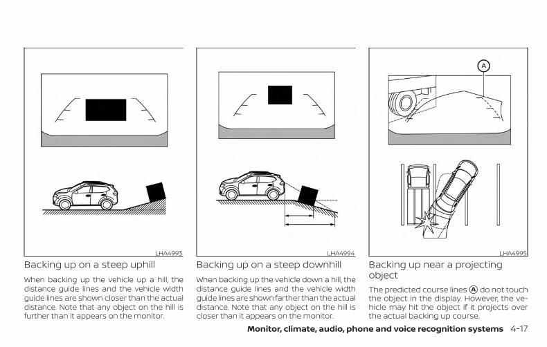
Backing up on a steep uphillWhen backing up the vehicle up a hill, thedistance guide lines and the vehicle widthguide lines are shown closer than the actualdistance. Note that any object on the hill isfurther than it appears on the monitor.
Backing up on a steep downhillWhen backing up the vehicle down a hill, thedistance guide lines and the vehicle widthguide lines are shown farther than the actualdistance. Note that any object on the hill iscloser than it appears on the monitor.
Backing up near a projectingobjectThe predicted course lines �A do not touchthe object in the display. However, the ve-hicle may hit the object if it projects overthe actual backing up course.
LHA4993 LHA4994 LHA4995
Monitor, climate, audio, phone and voice recognition systems 4-17

Backing up behind a projectingobjectThe position �C is shown farther than theposition �B in the display. However, the po-sition �C is actually at the same distance asthe position �A . The vehicle may hit the
object when backing up to the position �Aif the object projects over the actual back-ing up course.
HOW TO PARK WITH PREDICTEDCOURSE LINES
WARNING∙ If the tires are replaced with different
sized tires, the predicted course linesmay be displayed incorrectly.
∙ On a snow-covered or slippery road,there may be a difference betweenthe predicted course line and the ac-tual course line.
∙ If the battery is disconnected or be-comes discharged, the predictedcourse lines may be displayed incor-rectly. If this occurs, please performthe following procedures:
– Turn the steering wheel from lockto lock while the hybrid system isrunning.
– Drive the vehicle on a straight roadfor more than 5 minutes.
∙ When the steering wheel is turnedwith the ignition switch in the ACC po-sition, the predicted course lines maybe displayed incorrectly.
LHA4996
4-18 Monitor, climate, audio, phone and voice recognition systems

1. Visually check that the parking space issafe before parking your vehicle.
2. The rear view of the vehicle is displayedon the screen �A when the shift lever ismoved to the R (Reverse) position.
3. Slowly back up the vehicle adjustingthe steering wheel so that the pre-dicted course lines �B enter the park-ing space �C .
4. Maneuver the steering wheel to makethe vehicle width guide lines �D parallelto the parking space �C while referringto the predicted course lines.
5. When the vehicle is parked in the spacecompletely, move the shift lever to theP (Park) position and apply the parkingbrake.
HOW TO SWITCH THE DISPLAYWith the ignition switch in the ON position,press the CAMERA button or move the shiftlever to the R (Reverse) position to operatethe Intelligent Around View Monitor.
The Intelligent Around View Monitor dis-plays different split screen views depend-ing on the position of the shift lever. Pressthe CAMERA button to switch between theavailable views.
If the shift lever is in the R (Reverse) position,the available views are:
∙ Rear view/bird’s-eye view split screen
∙ Rear view/front-side view split screen
∙ Rear-wide view
LHA4769 LHA4770
Monitor, climate, audio, phone and voice recognition systems 4-19

If the shift lever is in the P (Park) or D (Drive)position, the available views are:
∙ Front view/bird’s-eye view split screen
∙ Front view/front-side view split screen
The display will switch from the IntelligentAround View Monitor screen when:
∙ The shift lever is in the D (Drive) positionand the vehicle speed increases aboveapproximately 6 mph (10 km/h)
∙ A different screen is selected.
ADJUSTING THE SCREEN1. While on the main menu screen, touch
the “Settings” key.
2. Use the arrow to tab to the next screenand touch the “Camera” key.
3. Touch the “Display Settings” key.
4. Touch the “Brightness”, “Contrast”, Tint”,“Color”, or “Black Level” key.
5. Adjust the item by touching the “+” or “–”key on the touch-screen display.
NOTE:
Do not adjust any of the display settingsof the Intelligent Around View Monitorwhile the vehicle is moving. Make surethe parking brake is firmly applied.
LHA3522
4-20 Monitor, climate, audio, phone and voice recognition systems

INTELLIGENT AROUND VIEWMONITOR SYSTEM LIMITATIONS
WARNINGListed below are the system limitationsfor Intelligent Around View Monitor.Failure to operate the vehicle in accor-dance with these system limitationscould result in serious injury or death.
∙ Do not use the Intelligent Around ViewMonitor with the outside mirrors inthe stored position, and make surethat the liftgate is securely closedwhen operating the vehicle using theIntelligent Around View Monitor.
∙ The apparent distance between ob-jects viewed on the Intelligent AroundView Monitor differs from the actualdistance.
∙ The cameras are installed on the frontgrille, the outside mirrors and abovethe rear license plate. Do not put any-thing such as a license plate frame onthe vehicle that covers or blocks theview of the cameras.
∙ When washing the vehicle with highpressure water, be sure not to spray itaround the cameras. Otherwise, wa-ter may enter the camera unit causingwater condensation on the lens, amalfunction, fire or an electric shock.
∙ Do not strike the cameras. They areprecision instruments. Doing so couldcause a malfunction or cause damageresulting in a fire or an electric shock.
There are some areas where the systemwill not show objects and the system doesnot warn of moving objects. When in thefront or rear view display, an object belowthe bumper or on the ground may not beviewed �1 . When in the bird’s-eye view, a tallobject near the seam �2 of the cameraviewing areas will not appear in the moni-tor.
The following are operating limitations anddo not represent a system malfunction:
∙ There may be a delay when switchingbetween views.
∙ When the temperature is extremelyhigh or low, the screen may not displayobjects clearly.
∙ When strong light directly shines on thecamera, objects may not be displayedclearly.
∙ The screen may flicker under fluores-cent light.
LHA3750
Monitor, climate, audio, phone and voice recognition systems 4-21

∙ The colors of objects on the IntelligentAround View Monitor may differ some-what from the actual color of objects.
∙ Objects on the Intelligent Around ViewMonitor may not be clear and the colorof the object may differ in a dark envi-ronment.
∙ There may be differences in sharpnessbetween each camera view of thebird’s-eye view.
∙ Do not use wax on the camera lens.Wipe off any wax with a clean cloth thathas been dampened with a diluted mildcleaning agent, then wipe with a drycloth. System temporarily unavailable
When the “!” icon is displayed on the screen,there are abnormal conditions in the Intel-ligent Around View Monitor. This will nothinder normal driving operation but thesystem should be inspected. It is recom-mended that you visit a NISSAN dealer forthis service.
When the “[X]” icon is displayed on thescreen, the camera image may be receiv-ing temporary electronic disturbancesfrom surrounding devices. This will not hin-der normal driving operation but the sys-tem should be inspected if it occurs fre-quently. It is recommended that you visit aNISSAN dealer for this service.
LHA3591 LHA3592
4-22 Monitor, climate, audio, phone and voice recognition systems

SYSTEM MAINTENANCE
CAUTION∙ Do not use alcohol, benzine or thinner
to clean the camera. This will causediscoloration.
∙ Do not damage the cameras as themonitor screen may be adverselyaffected.
If dirt, rain or snow accumulates on any ofthe cameras �1 , the Intelligent Around ViewMonitor may not display objects clearly.Clean the camera by wiping with a clothdampened with a diluted mild cleaningagent and then wiping with a dry cloth.
LHA3700
Monitor, climate, audio, phone and voice recognition systems 4-23

1. CAMERA buttonLHA4694
MOVING OBJECT DETECTION (MOD)(if so equipped)
4-24 Monitor, climate, audio, phone and voice recognition systems

WARNINGFailure to follow the warnings and in-structions for proper use of the MovingObject Detection (MOD) system couldresult in serious injury or death
∙ The MOD system is not a substitutefor proper vehicle operation and is notdesigned to prevent contact with ob-jects surrounding the vehicle. Whenmaneuvering, always use the outsidemirrors and rearview mirror and turnand check the surroundings to ensureit is safe to maneuver.
∙ The system is deactivated at speedsabove 5 mph (8 km/h). It is reactivatedat lower speeds.
∙ The MOD system is not designed todetect surrounding stationaryobjects.
The MOD system can inform the driver ofmoving objects near the vehicle whenbacking out of garages, maneuvering inparking lots and in other such instances.
The MOD system detects moving objectsby using image processing technology onthe image shown in the display.
MOD SYSTEM OPERATIONThe MOD system will turn on automaticallyunder the following conditions:
∙ When the shift lever is in the R (Reverse)position.
∙ When the CAMERA button is pressed toactivate the camera view on the display.
∙ When vehicle speed decreases belowapproximately 6 mph (10 km/h) and thecamera screen is displayed.
The MOD system operates in the followingconditions when the camera view is dis-played:
∙ When the shift lever is in the P (Park) or N(Neutral) position and the vehicle isstopped, the MOD system detects mov-ing objects in the bird’s-eye view. TheMOD system will not operate if the out-side mirrors are moving in or out, in thestowed position, or if either front door isopened.
Front and bird’s-eye viewsLHA4190
Monitor, climate, audio, phone and voice recognition systems 4-25

∙ When the shift lever is in the D (Drive)position and the vehicle speed is belowapproximately 6 mph (10 km/h), theMOD system detects moving objects inthe front view.
∙ When the shift lever is in the R (Reverse)position and the vehicle speed is belowapproximately 6 mph (10 km/h), theMOD system detects moving objects inthe rear view. The MOD system will notoperate if the liftgate is open.
The MOD system does not detect movingobjects in the front-side view. The MODicon is not displayed on the screen when inthis view.
When the MOD system detects moving ob-jects near the vehicle, a chime will be heardwhen in front or rear view and a yellowframe will be displayed on the view wherethe objects are detected. While the MODsystem continues to detect moving ob-jects, the yellow frame continues to be dis-played.
NOTE:
While the RCTA chime (if so equipped) isbeeping, the MOD system does notchime.
In the bird’s-eye view, the yellow frame �1 isdisplayed on each camera image (front,rear, right, left) depending on where mov-ing objects are detected.
The yellow frame �2 is displayed on eachview in the front view and rear view modes.
Rear and bird’s-eye viewsLHA4191
Rear and front-side viewsLHA4997
Rear-wide viewLHA4998
4-26 Monitor, climate, audio, phone and voice recognition systems

A blue MOD icon �3 is displayed in the viewwhere the MOD system is operative. A grayMOD icon is displayed in the view where theMOD system is not operative.
If the MOD system is turned off, the MODicon �3 is not displayed.
TURNING MOD ON AND OFF (if soequipped)Some vehicles include the option to allowthe MOD system to be turned on or off.
To turn the MOD system on or off:
1. Press the or button on thesteering wheel and select “Settings” inthe vehicle information display.
2. Using the buttons, select “DriverAssistance” and press the OK button.
3. Select “Parking Aids”.
4. Toggle ON or OFF “Moving Object” us-ing the OK button.
MOD SYSTEM LIMITATIONS
WARNINGListed below are the system limitationsfor MOD. Failure to operate the vehiclein accordance with these system limita-tions could result in serious injury ordeath.
∙ Do not use the MOD system whentowing a trailer. The system may notfunction properly.
∙ Excessive noise (for example, audiosystem volume or open vehicle win-dow) will interfere with the chimesound, and it may not be heard.
∙ The MOD system performance will belimited according to environmentalconditions and surrounding objectssuch as:
– When there is low contrast be-tween background and the movingobjects.
– When there is a blinking source oflight.
– When strong light such as anothervehicle’s headlight or sunlight ispresent.
– When camera orientation is not inits usual position, such as when amirror is folded.
– When there is dirt, water drops orsnow on the camera lens.
– When the position of the movingobjects in the display is notchanged.
∙ The MOD system might detect flowingwater droplets on the camera lens,white smoke from the muffler, mov-ing shadows, etc.
∙ The MOD system may not functionproperly depending on the speed, di-rection, distance or shape of the mov-ing objects.
∙ If your vehicle sustains damage to theparts where the camera is installed,leaving it misaligned or bent, thesensing zone may be altered and theMOD system may not detect objectsproperly.
∙ When the temperature is extremelyhigh or low, the screen may not dis-play objects clearly. This is not amalfunction.
Monitor, climate, audio, phone and voice recognition systems 4-27
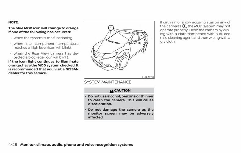
NOTE:
The blue MOD icon will change to orangeif one of the following has occurred:
∙ When the system is malfunctioning.
∙ When the component temperaturereaches a high level (icon will blink).
∙ When the Rear View camera has de-tected a blockage (icon will blink).
If the icon light continues to illuminateorange, have the MOD system checked. Itis recommended that you visit a NISSANdealer for this service.
SYSTEM MAINTENANCE
CAUTION∙ Do not use alcohol, benzine or thinner
to clean the camera. This will causediscoloration.
∙ Do not damage the camera as themonitor screen may be adverselyaffected.
If dirt, rain or snow accumulates on any ofthe cameras �1 , the MOD system may notoperate properly. Clean the camera by wip-ing with a cloth dampened with a dilutedmild cleaning agent and then wiping with adry cloth.
LHA3700
4-28 Monitor, climate, audio, phone and voice recognition systems

Adjust air flow direction by moving the ventslides.
Open or close the vents by using the dial.Move the dial toward the to open thevents or toward the to close them.
SideLHA4301
CenterLHA4302
RearLHA1134
VENTS
Monitor, climate, audio, phone and voice recognition systems 4-29

1. Front defroster button2. Temperature control dial (driver’s
side) / ON-OFF button3. MODE (manual air flow control)
button4. Display screen
5. A/C (air conditioner) button6. Temperature control dial (passen-
ger’s side)/DUAL (passenger’s sidetemperature control) button
7. Rear window and outsidemirror defroster switch
8. Fresh air intake button9. AUTO (automatic mode) button10. Fan speed control buttons11. Air recirculation button
WARNING∙ The air conditioner cooling function
operates only when the hybrid sys-tem is running.
∙ Do not leave children or adults whowould normally require the assis-tance of others alone in your vehicle.Pets should also not be left alone.They could accidentally injure them-selves or others through inadvertentoperation of the vehicle. Also, on hot,sunny days, temperatures in a closedvehicle could quickly become highenough to cause severe or possiblyfatal injuries to people or animals.
∙ Do not use the recirculation mode forlong periods as it may cause the inte-rior air to become stale and the win-dows to fog up.
LHA2875
HEATER AND AIR CONDITIONER(automatic)
4-30 Monitor, climate, audio, phone and voice recognition systems

NOTE:
∙ Odors from inside and outside the ve-hicle can build up in the air condi-tioner unit. Odor can enter the pas-senger compartment through thevents.
∙ When parking, set the heater and airconditioner controls to turn off air re-circulation to allow fresh air into thepassenger compartment. This shouldhelp reduce odors inside the vehicle.
AUTOMATIC OPERATIONCooling and/or dehumidifiedheating (AUTO)This mode may be used all year round asthe system automatically works to keep aconstant temperature. Air flow distribution,air intake control and fan speed are alsocontrolled automatically.
1. Press the AUTO button on. The indica-tor on the button will illuminate.
2. Turn the temperature control dial tothe left or right to set the desired tem-perature.
∙ The temperature of the passengercompartment will be maintained auto-matically. Air flow distribution, air intakecontrol and fan speed are also con-trolled automatically.
∙ A visible mist may be seen coming fromthe vents in hot, humid conditions asthe air is cooled rapidly. This does notindicate a malfunction.
3. You can individually set driver’s andfront passenger’s side temperature us-ing each temperature control dial.When the DUAL button is pressed orpassenger’s side temperature dial isturned, the DUAL indicator will comeon. To turn off the passenger’s sidetemperature control, press the DUALbutton.
Heating (A/C OFF)The air conditioner does not activate. Whenyou need to heat only, use this mode.
1. Press the AUTO button.
2. Turn the temperature control dial to setthe desired temperature.
∙ The temperature of the passengercompartment will be maintained auto-matically. Air flow distribution and fanspeed are also controlled automatically.
∙ Do not set the temperature lower thanthe outside air temperature. Otherwise,the system may not work properly.
∙ Not recommended if windows fog up.
Dehumidified defrosting ordefogging
1. Press the front defroster buttonon. The indicator light on the button willcome on.
2. Turn the temperature control dial to setthe maximum temperature to aid indefrosting or defogging.
∙ To quickly remove ice from the outsideof the windows, use the fan speed con-trol dial to set the fan speed to maxi-mum.
∙ As soon as possible after the wind-shield is clean, press the AUTO button toreturn to the automatic mode.
Monitor, climate, audio, phone and voice recognition systems 4-31

∙ When the front defroster button ispressed, the air conditioner will auto-matically be turned on at outside tem-peratures above 36°F (2°C). The air recir-culate mode automatically turns off,allowing outside air to be drawn into thepassenger compartment to further im-prove the defogging performance.When the air recirculate mode auto-matically turns off, the air fresh modewill automatically turn on.
Remote Hybrid Start withIntelligent Climate Control (if soequipped)Vehicles equipped with automatic climatecontrols and Remote Hybrid Start functionmay go into automatic heating or coolingmode when Remote Hybrid Start is acti-vated depending on outside and cabintemperatures. During this period, the cli-mate control display and buttons will beinoperable until the ignition switch isturned on. In Remote Hybrid Start defrost-ing mode, the rear window defroster andheated steering wheel (if so equipped) maybe activated automatically.
Voice Recognition logic (if soequipped)When the climate control system is on, thefan speed may be automatically loweredso that commands are more easily recog-nized. Fan speed can be adjusted usingthe fan speed control buttons, if de-sired.
MANUAL OPERATIONFan speed controlPress the fan speed control buttonsto manually control the fan speed.Press the AUTO button to return to auto-matic control of the fan speed.
Temperature control dialThe temperature control dial allows you toadjust the temperature of the outlet air. Tolower the temperature, turn the dial to theleft. To increase the temperature, turn thedial to the right. Temperature can be ad-justed on the driver’s and passenger’s side.
Air recirculationPress the air recirculation button torecirculate interior air inside the vehicle.The indicator light on the button willcome on.
The air recirculation cannot be activatedwhen the air conditioner is in thefront defrosting mode.When the outside temperature exceeds70°F (21°C), the air conditioning system maydefault to air recirculation mode automati-cally to reduce overall power consumption.To exit air recirculation mode, select thefresh air intake button (indicator will turnoff) to enter fresh air mode.
Fresh air intakePress the fresh air intake button todraw outside air into the passenger com-partment.
Automatic intake air controlIn the AUTO mode, the intake air will becontrolled automatically. When the outsidetemperature exceeds 70°F (21°C), the airconditioning system may default to air re-circulation mode automatically to reduceoverall power consumption. To exit air re-circulation mode, select the fresh air intakebutton to enter fresh air mode.
To manually control the intake air, pressthe air recirculation buttonor fresh air intake button. To return tothe automatic control mode ifthe fresh air indicator is illuminated,
4-32 Monitor, climate, audio, phone and voice recognition systems

press and hold the fresh air intakebutton for about 2 seconds. The fresh airindicator and air recirculation indicatorlights will flash twice, and then the intake airwill be controlled automatically. To returnto the automatic control mode ifthe air recirculation icon is illumi-nated, press and hold the air recircu-lation button for about 2 seconds.The air recirculation indicatorand fresh air intake indicator lightswill flash twice and the intake air will becontrolled automatically.
A/C (air conditioner) buttonThe button is provided only on vehiclesequipped with an air conditioner.
Start the hybrid system, turn the fan con-trol dial to the desired position and pushthe button to turn on the air condi-tioner. The indicator light comes on whenthe air conditioner is operating. To turn offthe air conditioner, push the buttonagain.The air conditioner cooling function op-erates only when the hybrid system isrunning.
Air flow controlPressing the MODE button manually con-trols air flow and selects the air outlet:
— Air flows mainly from centerand side vents.
— Air flows mainly from centerand side vents and footoutlets.
— Air flows mainly from foot out-lets and partly from defroster.
— Air flows mainly from defrosterand foot outlets.
To turn system offPress the ON-OFF button.
Rear window and outside mirrordefroster switchFor additional information, refer to “Rearwindow and outside mirror defrosterswitch” in the “Instruments and controls”section of this manual.
OPERATING TIPSThe sunload sensor, located on the top andcenter of the instrument panel, helps thesystem maintain a constant temperature.Do not put anything on or around this sen-sor.
LHA2949
Monitor, climate, audio, phone and voice recognition systems 4-33

∙ When the climate system is in auto-matic operation and the hybrid systemcoolant temperature and outside airtemperature are low, the air flow outletmay default to defroster mode for amaximum of 2 minutes 30 seconds.This is not a malfunction. After the cool-ant temperature warms up, the air flowoutlet will return to foot mode and op-eration will continue normally.
∙ When the outside and interior cabintemperatures are moderate to high, theintake setting may default to turn off airrecirculation to allow fresh air into thepassenger compartment. You may no-tice air flow from the foot mode, bi-levelmode, or side demist vent outlets for amaximum of 15 seconds. This may oc-cur when previous climate setting wassystem off. This is not a malfunction.After the initial warm air is expelled, theintake will return to automatic control,air flow outlet will return to previous set-tings, and operation will continue nor-mally. To exit, press any climate controlbutton.
∙ Keep the moonroof (if so equipped)closed while the air conditioner is in op-eration.
∙ If you feel that the air flow mode youhave selected and the outlets the air iscoming out do not match, selectthe mode.
∙ When you change the air flow mode,you may feel air flow from the feet ventsfor just a moment. This is not a mal-function.
The air conditioner system in your NISSANvehicle is charged with a refrigerant de-signed with the environment in mind.This refrigerant does not harm theearth’s ozone layer.
Special charging equipment and lubricantis required when servicing your NISSAN airconditioner. Using improper refrigerants orlubricants will cause severe damage toyour air conditioner system. For additionalinformation, refer to “Air conditioner sys-tem refrigerant and oil recommendations”in the “Technical and consumer informa-tion” section of this manual.
It is recommended that you visit a NISSANdealer to service your “environmentallyfriendly” air conditioner system.
WARNINGThe air conditioner system contains re-frigerant under high pressure. To avoidpersonal injury, any air conditioner ser-vice should be done only by an experi-enced technician with properequipment.
SERVICING AIR CONDITIONER
4-34 Monitor, climate, audio, phone and voice recognition systems
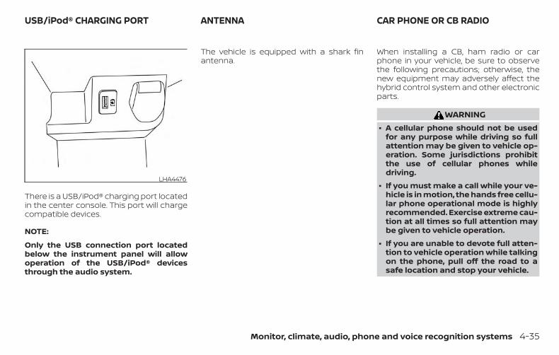
There is a USB/iPod® charging port locatedin the center console. This port will chargecompatible devices.
NOTE:
Only the USB connection port locatedbelow the instrument panel will allowoperation of the USB/iPod® devicesthrough the audio system.
The vehicle is equipped with a shark finantenna.
When installing a CB, ham radio or carphone in your vehicle, be sure to observethe following precautions; otherwise, thenew equipment may adversely affect thehybrid control system and other electronicparts.
WARNING∙ A cellular phone should not be used
for any purpose while driving so fullattention may be given to vehicle op-eration. Some jurisdictions prohibitthe use of cellular phones whiledriving.
∙ If you must make a call while your ve-hicle is in motion, the hands free cellu-lar phone operational mode is highlyrecommended. Exercise extreme cau-tion at all times so full attention maybe given to vehicle operation.
∙ If you are unable to devote full atten-tion to vehicle operation while talkingon the phone, pull off the road to asafe location and stop your vehicle.
LHA4476
USB/iPod® CHARGING PORT ANTENNA CAR PHONE OR CB RADIO
Monitor, climate, audio, phone and voice recognition systems 4-35

CAUTION∙ Keep the antenna as far away as pos-
sible from the electronic controlmodules.
∙ Keep the antenna wire more than 8 in(20 cm) away from the electronic con-trol system harnesses. Do not routethe antenna wire next to any harness.
∙ Adjust the antenna standing-waveratio as recommended by themanufacturer.
∙ Connect the ground wire from the CBradio chassis to the body.
∙ For additional information, it is rec-ommended that you visit a NISSANdealer for servicing.
4-36 Monitor, climate, audio, phone and voice recognition systems

5 Starting and driving
Precautions when starting and driving . . . . . . . . . . 5-4Exhaust gas (carbon monoxide) . . . . . . . . . . . . . . 5-4Three-way catalyst . . . . . . . . . . . . . . . . . . . . . . . . . . . 5-5Tire Pressure Monitoring System(TPMS). . . . . . . . . . . . . . . . . . . . . . . . . . . . . . . . . . . . . . . . 5-5On-pavement and off-road drivingprecautions . . . . . . . . . . . . . . . . . . . . . . . . . . . . . . . . . . 5-9Avoiding collision and rollover . . . . . . . . . . . . . . . 5-10Off-road recovery . . . . . . . . . . . . . . . . . . . . . . . . . . . 5-10Rapid air pressure loss . . . . . . . . . . . . . . . . . . . . . . 5-10Drinking alcohol/drugs and driving . . . . . . . . . . .5-11Driving safety precautions . . . . . . . . . . . . . . . . . . . 5-12
Push-button ignition switch . . . . . . . . . . . . . . . . . . . . 5-14Operating range. . . . . . . . . . . . . . . . . . . . . . . . . . . . . 5-15Push-button ignition switch positions . . . . . . . 5-15Emergency hybrid system shut off . . . . . . . . . . 5-16NISSAN Intelligent Key® batterydischarge . . . . . . . . . . . . . . . . . . . . . . . . . . . . . . . . . . . 5-16NISSAN Vehicle Immobilizer System . . . . . . . . . 5-17
Before starting the NISSAN PURE DRIVE®Hybrid System. . . . . . . . . . . . . . . . . . . . . . . . . . . . . . . . . . 5-17Starting the NISSAN PURE DRIVE® HybridSystem . . . . . . . . . . . . . . . . . . . . . . . . . . . . . . . . . . . . . . . . . 5-18
Remote Hybrid Start. . . . . . . . . . . . . . . . . . . . . . . . . 5-18
Driving the vehicle . . . . . . . . . . . . . . . . . . . . . . . . . . . . . . 5-19Continuously Variable Transmission(CVT) . . . . . . . . . . . . . . . . . . . . . . . . . . . . . . . . . . . . . . . . 5-19
Parking brake . . . . . . . . . . . . . . . . . . . . . . . . . . . . . . . . . . 5-24SPORT mode switch. . . . . . . . . . . . . . . . . . . . . . . . . . . . 5-25ECO mode switch . . . . . . . . . . . . . . . . . . . . . . . . . . . . . . 5-25Lane Departure Warning (LDW) . . . . . . . . . . . . . . . . . 5-26
LDW system operation . . . . . . . . . . . . . . . . . . . . . . 5-27How to enable/disable the LDW system . . . . . 5-28LDW system limitations. . . . . . . . . . . . . . . . . . . . . . 5-29System temporarily unavailable . . . . . . . . . . . . . 5-30System malfunction . . . . . . . . . . . . . . . . . . . . . . . . . 5-30System maintenance. . . . . . . . . . . . . . . . . . . . . . . . 5-30
Intelligent Lane Intervention (I-LI) . . . . . . . . . . . . . . . 5-31I-LI system operation . . . . . . . . . . . . . . . . . . . . . . . . 5-32How to enable/disable the I-LI system. . . . . . . 5-33I-LI system limitations . . . . . . . . . . . . . . . . . . . . . . . 5-34System temporarily unavailable . . . . . . . . . . . . . 5-35System malfunction . . . . . . . . . . . . . . . . . . . . . . . . . 5-36System maintenance. . . . . . . . . . . . . . . . . . . . . . . . 5-36
Blind Spot Warning (BSW) . . . . . . . . . . . . . . . . . . . . . . . 5-37BSW system operation . . . . . . . . . . . . . . . . . . . . . . 5-39How to enable/disable the BSW system . . . . . 5-40

BSW system limitations. . . . . . . . . . . . . . . . . . . . . . 5-41BSW driving situations . . . . . . . . . . . . . . . . . . . . . . . 5-42System temporarily unavailable . . . . . . . . . . . . . 5-45System maintenance. . . . . . . . . . . . . . . . . . . . . . . . 5-46
Rear Cross Traffic Alert (RCTA) . . . . . . . . . . . . . . . . . . 5-47RCTA system operation. . . . . . . . . . . . . . . . . . . . . .5-48How to enable/disable the RCTAsystem . . . . . . . . . . . . . . . . . . . . . . . . . . . . . . . . . . . . . . 5-50RCTA system limitations . . . . . . . . . . . . . . . . . . . . . 5-51System temporarily unavailable . . . . . . . . . . . . . 5-53System maintenance. . . . . . . . . . . . . . . . . . . . . . . . 5-54
Cruise control (if so equipped) . . . . . . . . . . . . . . . . . . 5-55Precautions on cruise control. . . . . . . . . . . . . . . . 5-55Cruise control operations. . . . . . . . . . . . . . . . . . . . 5-56
Intelligent Cruise Control (ICC) (if so equipped) . . 5-57How to select the cruise control mode . . . . . . 5-59Vehicle-to-vehicle distance controlmode . . . . . . . . . . . . . . . . . . . . . . . . . . . . . . . . . . . . . . . 5-59Vehicle-to-vehicle distance controlmode operation . . . . . . . . . . . . . . . . . . . . . . . . . . . . . 5-61Vehicle-to-vehicle distance controlmode switches. . . . . . . . . . . . . . . . . . . . . . . . . . . . . . 5-62Vehicle-to-vehicle distance controlmode limitations . . . . . . . . . . . . . . . . . . . . . . . . . . . . 5-69
System temporarily unavailable . . . . . . . . . . . . . 5-73System maintenance. . . . . . . . . . . . . . . . . . . . . . . . 5-75Conventional (fixed speed) cruisecontrol mode. . . . . . . . . . . . . . . . . . . . . . . . . . . . . . . . 5-76
Automatic Emergency Braking (AEB)(if so equipped) . . . . . . . . . . . . . . . . . . . . . . . . . . . . . . . . . 5-81
AEB system operation . . . . . . . . . . . . . . . . . . . . . . . 5-82Turning the AEB system on/off . . . . . . . . . . . . . .5-84AEB system limitations . . . . . . . . . . . . . . . . . . . . . .5-85System temporarily unavailable . . . . . . . . . . . . .5-86System malfunction . . . . . . . . . . . . . . . . . . . . . . . . . 5-87System maintenance. . . . . . . . . . . . . . . . . . . . . . . . 5-87
Automatic Emergency Braking (AEB) withPedestrian Detection (if so equipped) . . . . . . . . . . .5-89
AEB with Pedestrian Detection systemoperation. . . . . . . . . . . . . . . . . . . . . . . . . . . . . . . . . . . .5-90Turning the AEB with PedestrianDetection system ON/OFF . . . . . . . . . . . . . . . . . . 5-92AEB with Pedestrian Detection systemlimitations . . . . . . . . . . . . . . . . . . . . . . . . . . . . . . . . . . . 5-93System temporarily unavailable . . . . . . . . . . . . . 5-95System malfunction . . . . . . . . . . . . . . . . . . . . . . . . . 5-96System maintenance. . . . . . . . . . . . . . . . . . . . . . . . 5-96
Rear Automatic Braking (RAB) (if so equipped) . .5-98
RAB system operation . . . . . . . . . . . . . . . . . . . . . . . 5-99Turning the RAB system on/off . . . . . . . . . . . . . 5-100RAB system limitations . . . . . . . . . . . . . . . . . . . . . 5-101System malfunction . . . . . . . . . . . . . . . . . . . . . . . . 5-102System maintenance. . . . . . . . . . . . . . . . . . . . . . . 5-103
Break-in schedule . . . . . . . . . . . . . . . . . . . . . . . . . . . . . 5-103Fuel efficient driving tips . . . . . . . . . . . . . . . . . . . . . . . 5-104Increasing fuel economy . . . . . . . . . . . . . . . . . . . . . . 5-105All-Wheel Drive (AWD) (if so equipped) . . . . . . . . . . 5-105
All-Wheel Drive (AWD) LOCK switchoperations . . . . . . . . . . . . . . . . . . . . . . . . . . . . . . . . . 5-106
Parking/parking on hills . . . . . . . . . . . . . . . . . . . . . . . 5-108Power steering . . . . . . . . . . . . . . . . . . . . . . . . . . . . . . . . 5-109Brake system. . . . . . . . . . . . . . . . . . . . . . . . . . . . . . . . . . 5-110
Brake precautions . . . . . . . . . . . . . . . . . . . . . . . . . . 5-110Anti-lock Braking System (ABS) . . . . . . . . . . . . . .5-111Brake Assist . . . . . . . . . . . . . . . . . . . . . . . . . . . . . . . . 5-112
Vehicle Dynamic Control (VDC) system . . . . . . . . 5-112Brake force distribution. . . . . . . . . . . . . . . . . . . . . 5-114
Chassis Control . . . . . . . . . . . . . . . . . . . . . . . . . . . . . . . 5-115
Intelligent Trace Control (I-TC) . . . . . . . . . . . . . . . 5-115Intelligent Engine Brake (I-EB) . . . . . . . . . . . . . . . 5-116Active Ride Control (ARC) . . . . . . . . . . . . . . . . . . . .5-117
Hill start assist system. . . . . . . . . . . . . . . . . . . . . . . . . 5-118Rear Sonar System (RSS) (if so equipped) . . . . . . 5-119
System operation . . . . . . . . . . . . . . . . . . . . . . . . . . 5-120How to enable/disable the sonarsystem . . . . . . . . . . . . . . . . . . . . . . . . . . . . . . . . . . . . . 5-122Sonar limitations . . . . . . . . . . . . . . . . . . . . . . . . . . . 5-123System temporarily unavailable . . . . . . . . . . . . 5-123System maintenance. . . . . . . . . . . . . . . . . . . . . . . 5-124
Cold weather driving . . . . . . . . . . . . . . . . . . . . . . . . . . 5-124Freeing a frozen door lock . . . . . . . . . . . . . . . . . . 5-124Antifreeze . . . . . . . . . . . . . . . . . . . . . . . . . . . . . . . . . . 5-12412–volt battery. . . . . . . . . . . . . . . . . . . . . . . . . . . . . . 5-124Draining of coolant water. . . . . . . . . . . . . . . . . . . 5-125Tire equipment . . . . . . . . . . . . . . . . . . . . . . . . . . . . . 5-125Special winter equipment . . . . . . . . . . . . . . . . . . 5-125Driving on snow or ice . . . . . . . . . . . . . . . . . . . . . . 5-125

WARNING∙ Do not leave children or adults who
would normally require the assis-tance of others alone in your vehicle.Pets should also not be left alone.They could accidentally injure them-selves or others through inadvertentoperation of the vehicle. Also, on hot,sunny days, temperatures in a closedvehicle could quickly become highenough to cause severe or possiblyfatal injuries to people or animals.
∙ Properly secure all cargo with ropes orstraps to help prevent it from slidingor shifting. Do not place cargo higherthan the seatbacks. In a sudden stopor collision, unsecured cargo couldcause personal injury.
∙ To avoid raising the center of gravityexcessively, do not exceed the ratedcapacity of the roof rack (if soequipped) and evenly distribute theload.
EXHAUST GAS (carbon monoxide)
WARNING∙ Do not breathe exhaust gases; they
contain colorless and odorless carbonmonoxide. Carbon monoxide is dan-gerous. It can cause unconsciousnessor death.
∙ If you suspect that exhaust fumes areentering the vehicle, drive with allwindows fully open, and have the ve-hicle inspected immediately.
∙ Do not run the engine in closed spacessuch as a garage.
∙ Do not park the vehicle with the en-gine running for any extended lengthof time.
∙ Keep the rear vent windows, liftgates,doors and trunk lids (if so equipped)closed while driving, otherwise ex-haust gases could be drawn into thepassenger compartment. If you mustdrive with one of these open, followthese precautions:
1. Open all the windows.
2. Set the air recirculation but-ton to off and the fan control dial tohigh to circulate the air.
∙ If electrical wiring or other cable con-nections must pass to a trailerthrough the seal on the liftgate or thebody, follow the manufacturer’s rec-ommendation to prevent carbonmonoxide entry into the vehicle.
∙ The exhaust system and body shouldbe inspected by a qualified mechanicwhenever:
a. The vehicle is raised for service.
b. You suspect that exhaust fumesare entering into the passengercompartment.
c. You notice a change in the sound ofthe exhaust system.
d. You have had an accident involvingdamage to the exhaust system,underbody, or rear of the vehicle.
PRECAUTIONS WHEN STARTING ANDDRIVING
5-4 Starting and driving

THREE-WAY CATALYSTThe three-way catalyst is an emission con-trol device installed in the exhaust system.Exhaust gases in the three-way catalystare burned at high temperatures to helpreduce pollutants.
WARNING∙ The exhaust gas and the exhaust sys-
tem are very hot. Keep people, ani-mals or flammable materials awayfrom the exhaust systemcomponents.
∙ Do not stop or park the vehicle overflammable materials such as drygrass, waste paper or rags. They mayignite and cause a fire.
CAUTION∙ Do not use leaded gasoline. Deposits
from leaded gasoline will seriously re-duce the three-way catalyst’s abilityto help reduce exhaust pollutants.
∙ Keep your engine tuned up. Malfunc-tions in the ignition, fuel injection, orelectrical systems can cause overrichfuel flow into the three-way catalyst,causing it to overheat. Do not keepdriving if the engine misfires, or if no-ticeable loss of performance or otherunusual operating conditions are de-tected. Have the vehicle inspectedpromptly. It is recommended that youvisit a NISSAN dealer for this service.
∙ Avoid driving with an extremely lowfuel level. Running out of fuel couldcause the engine to misfire, damag-ing the three-way catalyst.
∙ Do not race the engine while warmingit up.
∙ Do not push or tow your vehicle tostart the hybrid system.
TIRE PRESSURE MONITORINGSYSTEM (TPMS)Each tire, including the spare (if provided),should be checked monthly when cold andinflated to the inflation pressure recom-mended by the vehicle manufacturer onthe vehicle placard or tire inflation pressurelabel. (If your vehicle has tires of a differentsize than the size indicated on the vehicle
placard or tire inflation pressure label, youshould determine the proper tire inflationpressure for those tires.)
As an added safety feature, your vehiclehas been equipped with a Tire PressureMonitoring System (TPMS) that illuminatesa low tire pressure telltale when one ormore of your tires is significantly under-inflated. Accordingly, when the low tirepressure telltale illuminates, you shouldstop and check your tires as soon as pos-sible, and inflate them to the proper pres-sure. Driving on a significantly under-inflated tire causes the tire to overheat andcan lead to tire failure. Under-inflation alsoreduces fuel efficiency and tire tread life,and may affect the vehicle’s handling andstopping ability.
Please note that the TPMS is not a substi-tute for proper tire maintenance, and it isthe driver’s responsibility to maintain cor-rect tire pressure, even if under-inflationhas not reached the level to trigger illumi-nation of the TPMS low tire pressure telltale.
Your vehicle has also been equipped with aTPMS malfunction indicator to indicatewhen the system is not operating properly.The TPMS malfunction indicator is com-bined with the low tire pressure telltale.
Starting and driving 5-5

When the system detects a malfunction,the telltale will flash for approximately oneminute and then remain continuously illu-minated. This sequence will continue uponsubsequent vehicle start-ups as long asthe malfunction exists. When the malfunc-tion indicator is illuminated, the systemmay not be able to detect or signal low tirepressure as intended. TPMS malfunctionsmay occur for a variety of reasons, includ-ing the installation of replacement or alter-nate tires or wheels on the vehicle thatprevent the TPMS from functioning prop-erly. Always check the TPMS malfunctiontelltale after replacing one or more tires orwheels on your vehicle to ensure that thereplacement or alternate tires and wheelsallow the TPMS to continue to functionproperly.
Additional information:
∙ When replacing a wheel without theTPMS such as the spare tire, the TPMSdoes not monitor the tire pressure ofthe spare tire.
∙ The TPMS will activate only when thevehicle is driven at speeds above16 mph (25 km/h). Also, this system maynot detect a sudden drop in tire pres-sure (for example, a flat tire while driv-ing).
∙ The low tire pressure warning light doesnot automatically turn off when the tirepressure is adjusted. After the tire is in-flated to the recommended pressure,the vehicle must be driven at speedsabove 16 mph (25 km/h) to activate theTPMS and turn off the low tire pressurewarning light. Use a tire pressure gaugeto check the tire pressure.
∙ The “Tire Pressure Low - Add Air” warn-ing appears each time the ignitionswitch is placed in the ON position aslong as the low tire pressure warninglight remains illuminated.
∙ The “Tire Pressure Low - Add Air” warn-ing appears in the vehicle informationdisplay when the low tire pressurewarning light is illuminated and low tirepressure is detected. The “Tire PressureLow - Add Air” warning turns off whenthe low tire pressure warning light turnsoff.
∙ The “Tire Pressure Low - Add Air” warn-ing does not appear if the low tire pres-sure warning light illuminates to indi-cate a TPMS malfunction.
∙ Tire pressure rises and falls dependingon the heat caused by the vehicle’s op-eration and the outside temperature.Do not reduce the tire pressure afterdriving because the tire pressure risesafter driving. Low outside temperaturecan lower the temperature of the airinside the tire which can cause a lowertire inflation pressure. This may causethe low tire pressure warning light toilluminate. If the warning light illumi-nates, check the tire pressure for all fourtires.
∙ The Tire and Loading Information labelis located in the driver’s door opening.
∙ You can also check the pressure of alltires (except the spare tire) on the ve-hicle information display screen. The or-der of the tire pressure figures dis-played on the screen corresponds withthe actual order of the tire position.
5-6 Starting and driving

For additional information, refer to “Low tirepressure warning light” in the “Instrumentsand controls” section and “Tire PressureMonitoring System (TPMS)” in the “In case ofemergency” section of this manual.
WARNING∙ Radio waves could adversely affect
electric medical equipment. Thosewho use a pacemaker should contactthe electric medical equipmentmanufacturer for the possible influ-ences before use.
∙ If the low tire pressure warning lightilluminates while driving, avoid sud-den steering maneuvers or abruptbraking, reduce vehicle speed, pull offthe road to a safe location and stopthe vehicle as soon as possible. Driv-ing with under-inflated tires may per-manently damage the tires and in-crease the likelihood of tire failure.Serious vehicle damage could occurand may lead to an accident and couldresult in serious personal injury.Check the tire pressure for all fourtires. Adjust the tire pressure to therecommended COLD tire pressureshown on the Tire and Loading Infor-mation label to turn the low tire pres-sure warning light off. If you have a flattire, replace it with a spare tire as soonas possible. (For additional informa-tion on changing a flat tire, refer to“Flat tire” in the “In case of emer-gency” section of this manual.)
∙ When replacing a wheel without theTPMS such as the spare tire, when aspare tire is mounted or a wheel isreplaced, tire pressure will not be indi-cated, the TPMS will not function andthe low tire pressure warning light willflash for approximately 1 minute. Thelight will remain on after 1 minute.Have your tires replaced and/or TPMSsystem reset as soon as possible. It isrecommended that you visit a NISSANdealer for this service.
∙ Replacing tires with those not origi-nally specified by NISSAN could affectthe proper operation of the TPMS.
∙ Do not inject any tire liquid or aerosoltire sealant into the tires, as this maycause a malfunction of the tire pres-sure sensors.
Starting and driving 5-7

CAUTION∙ The TPMS may not function properly
when the wheels are equipped withtire chains or the wheels are buried insnow.
∙ Do not place metalized film or anymetal parts (antenna, etc.) on the win-dows. This may cause poor receptionof the signals from the tire pressuresensors, and the TPMS will not func-tion properly.
Some devices and transmitters may tem-porarily interfere with the operation of theTPMS and cause the low tire pressurewarning light to illuminate.
Some examples are:
∙ Facilities or electric devices using simi-lar radio frequencies are near the ve-hicle.
∙ If a transmitter set to similar frequen-cies is being used in or near the vehicle.
∙ If a computer (or similar equipment) ora DC/AC converter is being used in ornear the vehicle.
The low tire pressure warning light mayilluminate in the following cases:
∙ If the vehicle is equipped with a wheeland tire without TPMS.
∙ If the TPMS has been replaced and theID has not been registered.
∙ If the wheel is not originally specified byNISSAN.
FCC Notice:
For USA:
This device complies with Part 15 of theFCC Rules. Operation is subject to the fol-lowing two conditions: (1) This devicemay not cause harmful interference, and(2) this device must accept any interfer-ence received, including interferencethat may cause undesired operation.
NOTE:
Changes or modifications not expresslyapproved by the party responsible forcompliance could void the user’s author-ity to operate the equipment.
For Canada:
This device complies with IndustryCanada licence-exempt RSS standard(s).Operation is subject to the following twoconditions: (1) this device may not causeinterference, and (2) this device must ac-cept any interference, including interfer-ence that may cause undesired opera-tion of the device.
TPMS with Easy-Fill Tire AlertWhen adding air to an under-inflated tire,the TPMS with Easy-Fill Tire Alert providesvisual and audible signals outside the ve-hicle to help you inflate the tires to the rec-ommended COLD tire pressure.
Vehicle set-up
1. Park the vehicle in a safe and level place.
2. Apply the parking brake and place theshift lever in the P (Park) position.
3. Place the ignition switch in the ON po-sition. Do not start the hybrid system.
5-8 Starting and driving

Operation
1. Add air to the tire.
2. After a few seconds, the hazard indica-tors will start flashing.
3. When the designated pressure isreached, the horn beeps once and thehazard indicators stop flashing.
4. Perform the above steps for each tire.
∙ If the tire is over-inflated more thanapproximately 4 psi (30 kPa), the hornbeeps and the hazard indicatorsflash three times. To correct the pres-sure, push the core of the valve stemon the tire briefly to release pressure.When the pressure reaches the des-ignated pressure, the horn beepsonce.
∙ If the hazard indicator does not flashwithin approximately 15 seconds af-ter starting to inflate the tire, it indi-cates that the Easy-Fill Tire Alert isnot operating.
∙ The TPMS will not activate the Easy-Fill Tire Alert under the following con-ditions:
– If there is interference from an exter-nal device or transmitter.
– The air pressure from the inflationdevice is not sufficient to inflate thetire.
– There is a malfunction in the TPMS.
– There is a malfunction in the horn orhazard indicators.
– The identification code of the tire’spressure sensor is not registered tothe system.
– The battery of the tire pressure sen-sor is low.
∙ If the Easy-Fill Tire Alert does not op-erate due to TPMS interference, movethe vehicle about 3 ft (1 m) backwardor forward and try again.
If the Easy-Fill Tire Alert is not working, use atire pressure gauge.
ON-PAVEMENT AND OFF-ROADDRIVING PRECAUTIONSUtility vehicles have a significantlyhigher rollover rate than other types ofvehicles.
They have higher ground clearance thanpassenger cars to make them capable ofperforming in a variety of on-pavementand off-road applications. This gives thema higher center of gravity than ordinary ve-hicles. An advantage of higher groundclearance is a better view of the road, allow-ing you to anticipate problems. However,they are not designed for cornering at thesame speeds as conventional 2-WheelDrive vehicles any more than low-slungsports cars are designed to perform satis-factorily under off-road conditions. If at allpossible, avoid sharp turns at high speeds.As with other vehicles of this type, failure tooperate this vehicle correctly may result inloss of control or vehicle rollover. In a roll-over crash, an unbelted person is signifi-cantly more likely to die than a personwearing a seat belt.
For additional information, refer to “Drivingsafety precautions” in this section.
Starting and driving 5-9

AVOIDING COLLISION ANDROLLOVER
WARNINGFailure to operate this vehicle in a safeand prudent manner may result in lossof control or an accident.
Be alert and drive defensively at all times.Obey all traffic regulations. Avoid excessivespeed, high speed cornering, or suddensteering maneuvers, because these drivingpractices could cause you to lose control ofyour vehicle.
As with any vehicle, loss of control couldresult in a collision with other vehicles orobjects or cause the vehicle to roll over,particularly if the loss of control causesthe vehicle to slide sideways.
Be attentive at all times, and avoid drivingwhen tired. Never drive when under the in-fluence of alcohol or drugs (including pre-scription or over-the-counter drugs whichmay cause drowsiness). Always wear yourseat belt as outlined in the “Safety – Seats,seat belts and supplemental restraint sys-tem” section of this manual, and also in-struct your passengers to do so.
Seat belts help reduce the risk of injury incollisions and rollovers. In a rollover crash,an unbelted or improperly belted personis significantly more likely to be injuredor killed than a person properly wearinga seat belt.
OFF-ROAD RECOVERYWhile driving, the right side or left sidewheels may unintentionally leave the roadsurface. If this occurs, maintain control ofthe vehicle by following the procedure be-low. Please note that this procedure is onlya general guide. The vehicle must be drivenas appropriate based on the conditions ofthe vehicle, road and traffic.
1. Remain calm and do not overreact.
2. Do not apply the brakes.
3. Maintain a firm grip on the steeringwheel with both hands and try to hold astraight course.
4. When appropriate, slowly release theaccelerator pedal to gradually slow thevehicle.
5. If there is nothing in the way, steer thevehicle to follow the road while vehiclespeed is reduced. Do not attempt todrive the vehicle back onto the roadsurface until vehicle speed is reduced.
6. When it is safe to do so, gradually turnthe steering wheel until both tires re-turn to the road surface. When all tiresare on the road surface, steer the ve-hicle to stay in the appropriate drivinglane.
∙ If you decide that it is not safe to re-turn the vehicle to the road surfacebased on vehicle, road or traffic con-ditions, gradually slow the vehicle to astop in a safe place off the road.
RAPID AIR PRESSURE LOSSRapid air pressure loss or a “blow-out” canoccur if the tire is punctured or is damageddue to hitting a curb or pothole. Rapid airpressure loss can also be caused by drivingon under-inflated tires.
Rapid air pressure loss can affect the han-dling and stability of the vehicle, especiallyat highway speeds.
5-10 Starting and driving
Help prevent rapid air pressure loss bymaintaining the correct air pressure andvisually inspecting the tires for wear anddamage. For additional information, referto “Wheels and tires” in the “Do-it-yourself ”section of this manual. If a tire rapidly losesair pressure or “blows-out” while driving,maintain control of the vehicle by followingthe procedure below. Please note that thisprocedure is only a general guide. The ve-hicle must be driven as appropriate basedon the conditions of the vehicle, road andtraffic.
WARNINGThe following actions can increase thechance of losing control of the vehicle ifthere is a sudden loss of tire air pres-sure. Losing control of the vehicle maycause a collision and result in personalinjury.
∙ The vehicle generally moves or pullsin the direction of the flat tire.
∙ Do not rapidly apply the brakes.
∙ Do not rapidly release the acceleratorpedal.
∙ Do not rapidly turn the steering wheel.
1. Remain calm and do not overreact.
2. Maintain a firm grip on the steeringwheel with both hands and try to hold astraight course.
3. When appropriate, slowly release theaccelerator pedal to gradually slow thevehicle.
4. Gradually steer the vehicle to a safelocation off the road and away fromtraffic if possible.
5. Lightly apply the brake pedal to gradu-ally stop the vehicle.
6. Turn on the hazard warning flashersand contact a roadside emergencyservice to change the tire. For addi-tional information, refer to “Changing aflat tire” in the “In case of emergency”section of this manual.
DRINKING ALCOHOL/DRUGS ANDDRIVING
WARNINGNever drive under the influence of alco-hol or drugs. Alcohol in the bloodstreamreduces coordination, delays reactiontime and impairs judgement. Driving af-ter drinking alcohol increases the likeli-hood of being involved in an accident in-juring yourself and others. Additionally, ifyou are injured in an accident, alcohol canincrease the severity of the injury.
NISSAN is committed to safe driving. How-ever, you must choose not to drive under theinfluence of alcohol. Every year thousands ofpeople are injured or killed in alcohol-relatedcollisions. Although the local laws vary onwhat is considered to be legally intoxicated,the fact is that alcohol affects all people dif-ferently and most people underestimate theeffects of alcohol.
Remember, drinking and driving don’t mix!That is true for drugs (over-the-counter,prescription) and illegal drugs, too. Don’tdrive if your ability to operate your vehicle isimpaired by alcohol, drugs, or some otherphysical condition.
Starting and driving 5-11

DRIVING SAFETY PRECAUTIONSYour NISSAN is designed for both normaland off-road use. However, avoid driving indeep water or mud as your NISSAN ismainly designed for leisure use, unlike aconventional off-road vehicle.
Remember that 2-Wheel Drive (2WD) mod-els are less capable than All-Wheel Drive(AWD) models for rough road driving andextrication when stuck in deep snow ormud, or the like.
Please observe the following precautions:
WARNING∙ Spinning the front wheels on slippery
surfaces may cause the AWD warningmessage to display and the AWD sys-tem to automatically switch from theAWD to the 2WD mode. This could re-duce the traction. Be especially care-ful when towing a trailer (AWDmodels).
∙ Drive carefully when off the road andavoid dangerous areas. Every personwho drives or rides in this vehicleshould be seated with their seat beltfastened. This will keep you and yourpassengers in position when drivingover rough terrain.
∙ Do not drive across steep slopes. In-stead drive either straight up orstraight down the slopes. Off-road ve-hicles can tip over sideways muchmore easily than they can forward orbackward.
∙ Many hills are too steep for any ve-hicle. If you drive up them, you maystall. If you drive down them, you maynot be able to control your speed. Ifyou drive across them, you may rollover.
∙ Do not shift gears while driving ondownhill grades as this could causeloss of control of the vehicle.
∙ Stay alert when driving to the top of ahill. At the top there could be a drop-off or other hazard that could causean accident.
∙ If your engine stalls or you cannotmake it to the top of a steep hill, neverattempt to turn around. Your vehiclecould tip or roll over. Always backstraight down in the R (Reverse) gearand apply brakes to control yourspeed.
∙ Heavy braking going down a hill couldcause your brakes to overheat andfade, resulting in loss of control andan accident. Apply brakes lightly anduse a low gear to control your speed.
∙ Unsecured cargo can be thrownaround when driving over rough ter-rain. Properly secure all cargo so it willnot be thrown forward and cause in-jury to you or your passengers.
∙ To avoid raising the center of gravityexcessively, do not exceed the ratedcapacity of the roof rack (if soequipped) and evenly distribute theload.
∙ Secure heavy loads in the cargo areaas far forward and as low as possible.Do not equip the vehicle with tireslarger than specified in this manual.This could cause your vehicle to rollover.
5-12 Starting and driving

∙ Do not grip the inside or spokes of thesteering wheel when driving off-road.The steering wheel could move sud-denly and injure your hands. Insteaddrive with your fingers and thumbs onthe outside of the rim.
∙ Before operating the vehicle, ensurethat the driver and all passengershave their seat belts fastened.
∙ Always drive with the floor mats inplace as the floor may become hot.
∙ Lower your speed when encounteringstrong crosswinds. With a higher cen-ter of gravity, your NISSAN is more af-fected by strong side winds. Slowerspeeds ensure better vehicle control.
∙ Do not drive beyond the performancecapability of the tires, even with AWDengaged.
∙ For AWD equipped vehicles, do not at-tempt to raise two wheels off theground and shift the transmission toany drive or reverse position with theengine running. Doing so may resultin drivetrain damage or unexpectedvehicle movement which could resultin serious vehicle damage or personalinjury.
∙ Do not attempt to test an AWDequipped vehicle on a 2-wheel dyna-mometer (such as the dynamometersused by some states for emissionstesting) or similar equipment even ifthe other two wheels are raised off theground. Make sure you inform test fa-cility personnel that your vehicle isequipped with AWD before it is placedon a dynamometer. Using the wrongtest equipment may result in drive-train damage or unexpected vehiclemovement which could result in seri-ous vehicle damage or personalinjury.
∙ When a wheel is off the ground due toan unlevel surface, do not spin thewheel excessively.
∙ Accelerating quickly, sharp steeringmaneuvers or sudden braking maycause loss of control.
∙ If at all possible, avoid sharp turningmaneuvers, particularly at highspeeds. Your NISSAN vehicle has ahigher center of gravity than a pas-senger car. The vehicle is not de-signed for cornering at the samespeeds as passenger cars.
∙ Failure to operate this vehicle cor-rectly could result in loss of controland/or a rollover accident.
∙ Always use tires of the same type,size, brand, construction (bias, bias-belted, or radial), and tread pattern onall four wheels. Install tire chains onthe front wheels when driving on slip-pery roads and drive carefully.
∙ Be sure to check the brakes immedi-ately after driving in mud or water. Foradditional information, refer to “Brakeprecautions” in this section.
∙ Avoid parking your vehicle on steephills. If you get out of the vehicle and itrolls forward, backward or sideways,you could be injured.
∙ Whenever you drive off-road throughsand, mud or water as deep as thewheel hub, more frequent mainte-nance may be required. For additionalinformation, refer to “Maintenanceunder severe operating conditions” inthe “Maintenance and schedules” sec-tion of this manual.
Starting and driving 5-13

WARNINGDo not operate the push-button igni-tion switch while driving the vehicle ex-cept in an emergency. (The NISSANPURE DRIVE® Hybrid System will turn offwhen the ignition switch is pushedthree consecutive times in quick suc-cession or the ignition switch is pushedand held for more than 2 seconds.) If thehybrid system stops while the vehicle isbeing driven, this could lead to a crashand serious injury.
When the ignition switch is pushed withoutdepressing the brake pedal, the ignitionswitch will illuminate.
Push the ignition switch center:
∙ Once to change to ON.
∙ Two times to change to OFF.
The ignition switch will automatically re-turn to the LOCK position when any door iseither opened or closed with the switch inthe OFF position.
The ignition lock is designed so that theignition switch position cannot beswitched to the OFF position until the shiftlever is moved to the P (Park) position.
When the ignition switch cannot be pushedtoward the OFF position, proceed as fol-lows:
1. Move the shift lever to the P (Park) posi-tion.
2. Push the ignition switch. The ignitionswitch will change to the ON position.
3. Push the ignition switch again to theOFF position.
The shift lever can be moved from the P(Park) position if the ignition switch is inthe ON position and the brake pedal isdepressed.
If the battery of the vehicle is discharged,the ignition switch cannot be movedfrom the LOCK position.
Some indicators and warnings for opera-tion are displayed on the vehicle informa-tion display. For additional information, re-fer to “Vehicle information display” in the“Instruments and controls” section of thismanual.
LSD2729
PUSH-BUTTON IGNITION SWITCH
5-14 Starting and driving

OPERATING RANGEThe Intelligent Key functions can only beused when the Intelligent Key is within thespecified operating range.
When the Intelligent Key battery is almostdischarged or strong radio waves are pres-ent near the operating location, the Intelli-gent Key system’s operating range be-comes narrower and may not functionproperly.
If the Intelligent Key is within the operatingrange, it is possible for anyone, even some-one who does not carry the Intelligent Key,to push the ignition switch to start the hy-brid system.
The operating range of the hybrid systemstart function is inside of the vehicle �1 .
∙ The luggage area is not included in theoperating range, but the Intelligent Keymay function.
∙ If the Intelligent Key is placed on theinstrument panel or inside the glovebox, storage bin or door pocket, the In-telligent Key may not function.
∙ If the Intelligent Key is placed near thedoor or window outside the vehicle, theIntelligent Key may function.
PUSH-BUTTON IGNITION SWITCHPOSITIONSLOCK (Normal parking position):
The ignition switch can only be locked inthis position.
The ignition switch will lock when any dooris opened or closed with the ignitionswitched off.
ON (Normal operating position):
This position turns on the ignition systemand electrical accessories.
ON has a battery saver feature that willplace the ignition switch in the OFF posi-tion, if the vehicle is not running, after sometime under the following conditions:
∙ All doors are closed.
∙ The shift lever is in P (Park).
The battery saver feature will be canceled ifany of the following occur:
∙ Any door is opened.
∙ The shift lever is moved out of the P(Park) position.
∙ The ignition switch changes position.
CAUTIONDo not leave the vehicle with the igni-tion switch in the ON position when theengine is not running for an extendedperiod. This can discharge the battery.
LSD2020
Starting and driving 5-15

OFF:
The ignition switch is in the OFF positionwhen the hybrid system is turned off usingthe ignition switch. No lights will illuminateon the ignition switch.
AUTO ACC:
With the vehicle in the P (Park) position, theIntelligent Key with you, and the ignitionswitch placed from the ON to the OFF po-sition, the radio can still be used for a periodof time, or until the driver’s door is opened.
After a period of time, functions such asradio, navigation, and Bluetooth® Hands-Free Phone System may be restarted bypressing the “POWER button/VOLUME con-trol knob” or the key fob unlock button. Foradditional information, refer to the sepa-rate NissanConnect® Owner’s Manual.
EMERGENCY HYBRID SYSTEMSHUT OFFTo shut off the hybrid system in an emer-gency situation while driving, perform thefollowing procedure:
∙ Rapidly push the ignition switch threeconsecutive times in less than 1.5 sec-onds, or
∙ Push and hold the ignition switch formore than 2 seconds.
NISSAN INTELLIGENT KEY®BATTERY DISCHARGEIf the battery of the NISSAN Intelligent Key®is discharged or environmental conditionsinterfere with the Intelligent Key operation,start the hybrid system according to thefollowing procedure:
1. Place the shift lever in the P (Park) posi-tion.
2. Firmly apply the foot brake.
3. Touch the ignition switch with the Intel-ligent Key as illustrated. (A chime willsound.)
SSD0860
5-16 Starting and driving

(After step 3 is performed, when theignition switch is pushed without de-pressing the brake pedal, the ignitionswitch position will change to ON.)
4. Push the ignition switch while depress-ing the brake pedal within 10 secondsafter the chime sounds. The hybridsystem will start.
NOTE:
∙ When the ignition switch is pushed tothe ON position or the hybrid systemis started by the above procedure, theIntelligent Key battery discharge in-dicator appears in the vehicle infor-mation display even when the Intelli-gent Key is inside the vehicle. This isnot a malfunction. To turn off the In-telligent Key battery discharge indi-cator, touch the ignition switch withthe Intelligent Key again.
∙ If the Intelligent Key battery dis-charge indicator appears, replace thebattery as soon as possible. For addi-tional information, refer to “Batteryreplacement” in the “Do-it-yourself”section of this manual.
NISSAN VEHICLE IMMOBILIZERSYSTEMThe NISSAN Vehicle Immobilizer Systemwill not allow the hybrid system to startwithout the use of the registered key.
If the hybrid system fails to start using aregistered key (for example, when interfer-ence is caused by another registered key,an automated toll road device or auto-matic payment device on the key ring), re-start the hybrid system using the followingprocedure:
1. Leave the ignition switch in the ON po-sition for approximately 5 seconds.
2. Place the ignition switch in the OFF orLOCK position, and wait approximately10 seconds.
3. Repeat steps 1 and 2.
4. Restart the hybrid system while hold-ing the device (which may have causedthe interference) separate from theregistered key.
If the no start condition re-occurs, NISSANrecommends placing the registered key ona separate key ring to avoid interferencefrom other devices.
∙ Make sure the area around the vehicle isclear.
∙ Check fluid levels such as engine oil,coolant, brake fluid, and windshield-washer fluid as frequently as possible,or at least whenever you refuel.
∙ Check that all windows and lights areclean.
∙ Visually inspect tires for their appear-ance and condition. Also check tires forproper inflation.
∙ Check that all doors are closed.
∙ Position seat and adjust head re-straints.
∙ Adjust inside and outside mirrors.
∙ Fasten seat belts and ask all passen-gers to do likewise.
∙ Check the operation of warning lightswhen the ignition switch is placed in theON position. For additional information,refer to “Warning lights, indicator lightsand audible reminders” in the “Instru-ments and controls” section of thismanual.
BEFORE STARTING THE NISSANPURE DRIVE® HYBRID SYSTEM
Starting and driving 5-17

1. Apply the parking brake.
2. Move the shift lever to P (Park) or N(Neutral). P (Park) is recommended.
The NISSAN PURE DRIVE® Hybrid Sys-tem is designed not to operate if theshift lever is in any of the driving po-sitions.
3. Depress the brake pedal and push theignition switch to start the hybrid sys-tem. The READY to drive indicator willilluminate on the meter.
When starting the hybrid system atvery low outside temperatures, theREADY to drive indicator light willflash and it may take longer for theREADY to drive indicator light to illu-minate. When the READY to drive in-dicator light is flashing, it cannot beshifted out of P (Park).
NOTE:
Do not start the vehicle in the N (Neutral)position (in cold conditions only).
The hybrid system may not start evenwith the READY to drive indicator lightilluminated. Once the READY to drive in-dicator light is illuminated you may be-gin driving the vehicle.
NOTE:
Care should be taken to avoid situationsthat can lead to potential 12-volt batterydischarge and potential no-start condi-tions such as:
1. Installation or extended use of elec-tronic accessories that consume 12-volt battery power when the engineis not running (phone chargers, GPS,DVD players, etc.).
2. The vehicle is not driven regularlyand/or only driven short distances.
In these cases, the 12-volt battery mayneed to be charged to maintain 12-voltbattery health.
REMOTE HYBRID STARTVehicles started with the Remote HybridStart require the ignition switch to beplaced in the ON position before the shiftlever can be moved from the P (Park) posi-tion. To place the ignition switch in the ONposition, follow these steps:
1. Make sure that the Intelligent Key is onyou.
2. Apply the brake.
3. Push the ignition switch once to the ONposition.
For additional information, refer to “NISSANIntelligent Key®” in the “Pre-driving checksand adjustments” section of this manual.
STARTING THE NISSAN PURE DRIVE®HYBRID SYSTEM
5-18 Starting and driving

CONTINUOUSLY VARIABLETRANSMISSION (CVT)
WARNING∙ Do not depress the accelerator pedal
while shifting from P (Park) or N (Neu-tral) to R (Reverse), D (Drive), or M(Manual shift mode). Always depressthe brake pedal until shifting is com-pleted. Failure to do so could causeyou to lose control and have anaccident.
∙ Cold engine idle speed is high, so usecaution when shifting into a forwardor reverse gear before the engine haswarmed up.
∙ Do not downshift abruptly on slipperyroads. This may cause a loss ofcontrol.
∙ Never shift to either the P (Park) or R(Reverse) position while the vehicle ismoving forward and P (Park) or D(Drive) position while the vehicle is re-versing. This could cause an accidentor damage the transmission.
CAUTION∙ To avoid possible damage to your ve-
hicle, when stopping the vehicle on anuphill grade, do not hold the vehicle bydepressing the accelerator pedal. Thefoot brake should be used for thispurpose.
∙ Except in an emergency, do not shiftto the N (Neutral) position while driv-ing. Coasting with the transmission inthe N (Neutral) position may cause se-rious damage to the transmission.
The CVT in your vehicle is electronicallycontrolled to produce maximum powerand smooth operation.
The recommended operating proceduresfor this transmission are shown on the fol-lowing pages. Follow these procedures formaximum vehicle performance and driv-ing enjoyment.
Engine power may be automatically re-duced to protect the CVT if the enginespeed increases quickly when driving onslippery roads or while being tested onsome dynamometers.
Starting the vehicle1. After starting the hybrid system, fully
depress the foot brake pedal beforemoving the shift lever out of the P (Park)position.This Continuously Variable Transmis-sion is designed so that the footbrake pedal must be depressed be-fore shifting from P (Park) to any driv-ing position while the ignition switchis in the ON position.The shift lever cannot be moved outof the P (Park) position and into anyof the other positions if the ignitionswitch is placed in the LOCK or OFFposition.
2. Keep the foot brake pedal depressedand move the shift lever to a drivingposition.
3. Release the parking brake and footbrake pedal, and then gradually startthe vehicle in motion.
DRIVING THE VEHICLE
Starting and driving 5-19

WARNING∙ Do not depress the accelerator pedal
while shifting from P (Park) or N (Neu-tral) to R (Reverse), D (Drive) or M(Manual shift mode) position. Alwaysdepress the brake pedal until shiftingis completed. Failure to do so couldcause you to lose control and have anaccident.
∙ Cold engine idle speed is high, so usecaution when shifting into a forwardor reverse gear before the engine haswarmed up.
∙ Do not downshift abruptly on slipperyroads. This may cause a loss ofcontrol.
∙ Never shift to either the P (Park) or R(Reverse) position while the vehicle ismoving forward and P (Park) or D(Drive) position while the vehicle is re-versing. This could cause an accidentor damage the transmission.
CAUTION∙ To avoid possible damage to your ve-
hicle, when stopping the vehicle on anuphill grade, do not hold the vehicle bydepressing the accelerator pedal. Thefoot brake should be used for thispurpose.
∙ Except in an emergency, do not shiftto the N (Neutral) position while driv-ing. Coasting with the transmission inthe N (Neutral) position may cause se-rious damage to the transmission.
ShiftingAfter starting the hybrid system, fully de-press the brake pedal, press the shift leverbutton and move the shift lever from the P(Park) position to any of the desired shiftpositions.
LSD2691
5-20 Starting and driving

WARNINGApply the parking brake if the shift leveris in any position while the hybrid sys-tem is not running. Failure to do socould cause the vehicle to move unex-pectedly or roll away and result in seri-ous personal injury or propertydamage.
CAUTIONUse the P (Park) or R (Reverse) positiononly when the vehicle is completelystopped.
P (Park)
CAUTIONTo prevent transmission damage, usethe P (Park) position only when the ve-hicle is completely stopped.
Use the P (Park) shift lever position whenthe vehicle is parked or when starting thehybrid system. Make sure the vehicle iscompletely stopped. The brake pedalmust be depressed and the shift leverbutton pressed in to move the shift leverfrom N (Neutral) or any drive position to P(Park). Apply the parking brake. When park-
ing on a hill, apply the parking brake first,then move the shift lever to the P (Park)position.
R (Reverse)
CAUTIONTo prevent transmission damage, usethe R (Reverse) position only when thevehicle is completely stopped.
Use the R (Reverse) position to back up.Make sure the vehicle is completelystopped before selecting the R (Reverse)position. The brake pedal must be de-pressed and the shift lever buttonpressed to move the shift lever from P(Park), N (Neutral) or any drive position toR (Reverse).
N (Neutral)
Neither forward nor reverse gear is en-gaged. The hybrid system can be started inthis position. You may shift to N (Neutral)and restart a stalled hybrid system whilethe vehicle is moving.
D (Drive)
Use this position for all normal forwarddriving.
Manual shift modeWhen the shift lever is in the manual shiftgate, the transmission is ready for themanual shift mode. Shift ranges can beselected manually by moving the shift le-ver up or down. To cancel manual shiftmode, return the shift lever to the D (Drive)position. The transmission returns to auto-matic driving mode.
When the shift lever is shifted from D (Drive)to the manual shift gate with the vehiclestopped or while driving, the transmissionenters the manual shift mode. Shift rangescan be selected manually. In the manualshift mode, the shift range is displayed onthe position indicator in the meter. Whenmoving the shift lever to the manual shiftgate, the position indicator displays 1 (1st)up to 7 (7th) depending on vehicle speed.
Shift ranges up or down one by one asfollows:
1⇔ 2 ⇔ 3 ⇔ 4 ⇔ 5 ⇔ 6 ⇔ 7
7 (7th)
Use this position for all normal forwarddriving at highway speeds.
Starting and driving 5-21

6 (6th) and 5 (5th)
Use this position when driving up longslopes, or for engine braking when drivingdown long slopes.
4 (4th), 3 (3rd) and 2 (2nd)
Use these positions for hill climbing or en-gine braking on downhill grades.
1 (1st)
Use this position when climbing steep hillsslowly or when driving slowly, or for maxi-mum engine braking on steep downhillgrades.
∙ Remember not to drive at high speedsfor extended periods of time in lowerthan 7th gear. This reduces fueleconomy.
When shifting up
Move the shift lever to the + (up) side. (Shiftsto higher range.)
When shifting down
Move the shift lever to the � (down) side.(Shifts to lower range.)
∙ The transmission will automaticallydownshift the gears. (For example, if youselect the 3rd range, the transmissionwill shift down between the 3rd and 1stgears.)
∙ Moving the shift lever rapidly to thesame side twice will shift the ranges insuccession.
When canceling the manual shift mode
Return the shift lever to the D (Drive) posi-tion to return the transmission to the nor-mal driving mode.
∙ In the manual shift mode, the trans-mission may not shift to the selectedgear. This helps maintain driving per-formance and reduces the chance ofvehicle damage or loss of control.
∙ When this situation occurs, the Con-tinuously Variable Transmission (CVT)position indicator light will blink andthe chime will sound.
∙ In the manual shift mode, the trans-mission may shift up automatically toa higher range than selected if theengine speed is too high. When thevehicle speed decreases, the trans-mission automatically shifts downand shifts to 1st gear before the ve-hicle comes to a stop.
∙ CVT operation is limited to automaticdrive mode when CVT fluid tempera-ture is extremely low even if manualshift mode is selected. This is not a mal-function. When CVT fluid warms up,manual mode can be selected.
∙ When the CVT fluid temperature is high,the shift range may upshift in lowerrpm than usual. This is not a malfunc-tion.
5-22 Starting and driving
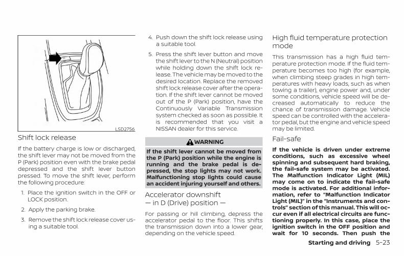
Shift lock releaseIf the battery charge is low or discharged,the shift lever may not be moved from theP (Park) position even with the brake pedaldepressed and the shift lever buttonpressed. To move the shift lever, performthe following procedure:
1. Place the ignition switch in the OFF orLOCK position.
2. Apply the parking brake.
3. Remove the shift lock release cover us-ing a suitable tool.
4. Push down the shift lock release usinga suitable tool.
5. Press the shift lever button and movethe shift lever to the N (Neutral) positionwhile holding down the shift lock re-lease. The vehicle may be moved to thedesired location. Replace the removedshift lock release cover after the opera-tion. If the shift lever cannot be movedout of the P (Park) position, have theContinuously Variable Transmissionsystem checked as soon as possible. Itis recommended that you visit aNISSAN dealer for this service.
WARNINGIf the shift lever cannot be moved fromthe P (Park) position while the engine isrunning and the brake pedal is de-pressed, the stop lights may not work.Malfunctioning stop lights could causean accident injuring yourself and others.
Accelerator downshift— in D (Drive) position —For passing or hill climbing, depress theaccelerator pedal to the floor. This shiftsthe transmission down into a lower gear,depending on the vehicle speed.
High fluid temperature protectionmodeThis transmission has a high fluid tem-perature protection mode. If the fluid tem-perature becomes too high (for example,when climbing steep grades in high tem-peratures with heavy loads, such as whentowing a trailer), engine power and, undersome conditions, vehicle speed will be de-creased automatically to reduce thechance of transmission damage. Vehiclespeed can be controlled with the accelera-tor pedal, but the engine and vehicle speedmay be limited.
Fail-safeIf the vehicle is driven under extremeconditions, such as excessive wheelspinning and subsequent hard braking,the fail-safe system may be activated.The Malfunction Indicator Light (MIL)may come on to indicate the fail-safemode is activated. For additional infor-mation, refer to “Malfunction IndicatorLight (MIL)” in the “Instruments and con-trols” section of this manual. This will oc-cur even if all electrical circuits are func-tioning properly. In this case, place theignition switch in the OFF position andwait for 10 seconds. Then push the
LSD2756
Starting and driving 5-23

switch back to the ON position. The ve-hicle should return to its normal operat-ing condition. If it does not return to itsnormal operating condition, have thetransmission checked. It is recom-mended that you visit a NISSAN dealerfor this service.
WARNINGWhen the high fluid temperature pro-tection mode or fail-safe operation oc-curs, vehicle speed may be gradually re-duced. The reduced speed may be lowerthan other traffic, which could increasethe chance of a collision. Be especiallycareful when driving. If necessary, pullto the side of the road at a safe placeand allow the transmission to return tonormal operation, or have it repaired ifnecessary.
WARNING∙ Be sure the parking brake is fully re-
leased before driving. Failure to do socan cause brake failure and lead to anaccident.
∙ Do not release the parking brake fromoutside the vehicle.
∙ Do not use the shift lever in place ofthe parking brake. When parking, besure the parking brake is fullyengaged.
∙ To help avoid risk of injury or deaththrough unintended operation of thevehicle and/or its systems, do notleave children, people who require theassistance of others or pets unat-tended in your vehicle. Additionally,the temperature inside a closed ve-hicle on a warm day can quickly be-come high enough to cause a signifi-cant risk of injury or death to peopleand pets.
To engage: Firmly depress the parkingbrake.
To release:
1. Firmly apply the foot brake.
2. Move the shift lever to the P (Park) po-sition.
3. Firmly depress the parking brake pedaland it will release.
4. Before driving, be sure the brake warn-ing light goes out.
LSD0158
PARKING BRAKE
5-24 Starting and driving

The SPORT mode switch adjusts the en-gine and transmission points to enhanceperformance. Push the SPORT modeswitch on the instrument panel to activate.The SPORT mode indicator appears in themeter.
NOTE:
In the SPORT mode, fuel economy maybe reduced.
The ECO mode helps to enhance the fueleconomy by controlling the throttle sensi-tivity and transmission points.
To turn on the ECO mode, push the ECOmode switch. The ECO mode indicator willremain lit while the mode is active.
To turn off the ECO mode, push the ECOmode switch again. The ECO mode indica-tor will turn off.
The ECO mode cannot be turned off whilethe accelerator pedal is depressed, even ifthe ECO mode switch is pushed to OFF.Release the accelerator pedal to turn offthe ECO mode.
The ECO mode will turn off automatically ifa malfunction occurs in the system.
Turn off the ECO mode or depress the ac-celerator pedal fully when:
∙ Driving with a heavy load of passengersor cargo in the vehicle
∙ Driving on a steep uphill slope
∙ ECO mode may affect air conditionerperformance
NOTE:
Selecting this drive mode will not neces-sarily improve fuel economy as manydriving factors influence its effective-ness.
LIC2417 LIC2416
SPORT MODE SWITCH ECO MODE SWITCH
Starting and driving 5-25
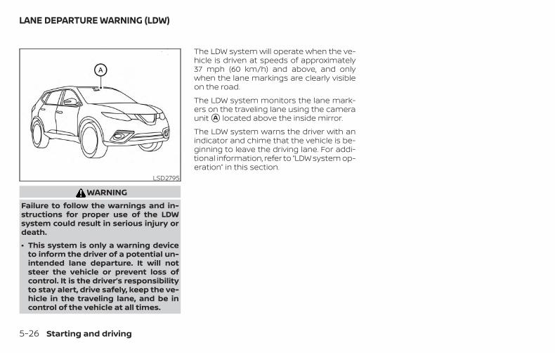
WARNINGFailure to follow the warnings and in-structions for proper use of the LDWsystem could result in serious injury ordeath.
∙ This system is only a warning deviceto inform the driver of a potential un-intended lane departure. It will notsteer the vehicle or prevent loss ofcontrol. It is the driver’s responsibilityto stay alert, drive safely, keep the ve-hicle in the traveling lane, and be incontrol of the vehicle at all times.
The LDW system will operate when the ve-hicle is driven at speeds of approximately37 mph (60 km/h) and above, and onlywhen the lane markings are clearly visibleon the road.
The LDW system monitors the lane mark-ers on the traveling lane using the cameraunit �A located above the inside mirror.
The LDW system warns the driver with anindicator and chime that the vehicle is be-ginning to leave the driving lane. For addi-tional information, refer to “LDW system op-eration” in this section.
LSD2795
LANE DEPARTURE WARNING (LDW)
5-26 Starting and driving

LDW SYSTEM OPERATIONThe LDW system provides a lane departurewarning function when the vehicle is drivenat speeds of approximately 37 mph(60 km/h) and above and the lane mark-ings are clear. When the vehicle ap-proaches either the left or the right side ofthe traveling lane, a warning chime willsound and the LDW indicator on the instru-ment panel will blink to alert the driver.
The warning function will stop when thevehicle returns inside of the lane markers.
LSD3307
Starting and driving 5-27
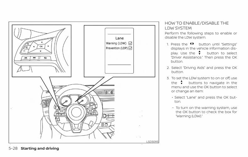
HOW TO ENABLE/DISABLE THELDW SYSTEMPerform the following steps to enable ordisable the LDW system.
1. Press the button until “Settings”displays in the vehicle information dis-play. Use the button to select“Driver Assistance.” Then press the OKbutton.
2. Select “Driving Aids” and press the OKbutton.
3. To set the LDW system to on or off, usethe buttons to navigate in themenu and use the OK button to selector change an item:
∙ Select “Lane” and press the OK but-ton.
– To turn on the warning system, usethe OK button to check the box for“Warning (LDW).”
LSD3093
5-28 Starting and driving

LDW SYSTEM LIMITATIONS
WARNINGListed below are the system limitationsfor the LDW system. Failure to follow thewarnings and instructions for properuse of the LDW system could result inserious injury or death.
∙ The system will not operate at speedsbelow approximately 37 mph(60 km/h) or if it cannot detect lanemarkers.
∙ Excessive noise will interfere with thewarning chime sound, and the chimemay not be heard.
∙ Do not use the LDW system under thefollowing conditions as it may notfunction properly:
– During bad weather (rain, fog,snow, etc.).
– When driving on slippery roads,such as on ice or snow.
– When driving on winding or un-even roads.
– When there is a lane closure due toroad repairs.
– When driving in a makeshift ortemporary lane.
– When driving on roads where thelane width is too narrow.
– When driving without normal tireconditions (for example, tire wear,low tire pressure, installation ofspare tire, tire chains, nonstandardwheels).
– When the vehicle is equipped withnon-original brake parts or sus-pension parts.
– When you are towing a trailer orother vehicle.
∙ The system may not function prop-erly under the following conditions:
– On roads where there are multipleparallel lane markers; lane mark-ers that are faded or not paintedclearly; yellow painted lane mark-ers; non-standard lane markers; orlane markers covered with water,dirt, snow, etc.
– On roads where the discontinuedlane markers are still detectable.
– On roads where there are sharpcurves.
– On roads where there are sharplycontrasting objects, such as shad-ows, snow, water, wheel ruts,seams or lines remaining afterroad repairs. (The LDW systemcould detect these items as lanemarkers.)
– On roads where the traveling lanemerges or separates.
– When the vehicle’s traveling direc-tion does not align with the lanemarker.
– When traveling close to the vehiclein front of you, which obstructs thelane camera unit detection range.
– When rain, snow, dirt or an objectadheres to the windshield in frontof the lane camera unit.
– When the headlights are not brightdue to dirt on the lens or if the aim-ing is not adjusted properly.
– When strong light enters the lanecamera unit. (For example, the lightdirectly shines on the front of thevehicle at sunrise or sunset.)
Starting and driving 5-29
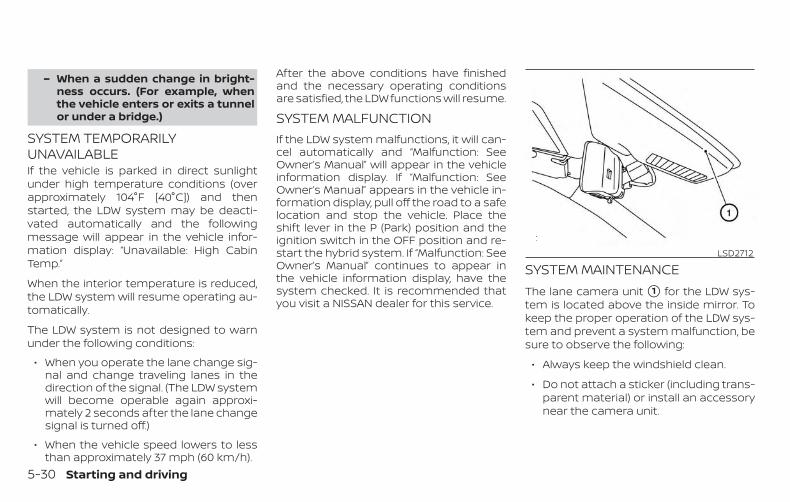
– When a sudden change in bright-ness occurs. (For example, whenthe vehicle enters or exits a tunnelor under a bridge.)
SYSTEM TEMPORARILYUNAVAILABLEIf the vehicle is parked in direct sunlightunder high temperature conditions (overapproximately 104°F [40°C]) and thenstarted, the LDW system may be deacti-vated automatically and the followingmessage will appear in the vehicle infor-mation display: “Unavailable: High CabinTemp.”
When the interior temperature is reduced,the LDW system will resume operating au-tomatically.
The LDW system is not designed to warnunder the following conditions:
∙ When you operate the lane change sig-nal and change traveling lanes in thedirection of the signal. (The LDW systemwill become operable again approxi-mately 2 seconds after the lane changesignal is turned off.)
∙ When the vehicle speed lowers to lessthan approximately 37 mph (60 km/h).
After the above conditions have finishedand the necessary operating conditionsare satisfied, the LDW functions will resume.
SYSTEM MALFUNCTIONIf the LDW system malfunctions, it will can-cel automatically and “Malfunction: SeeOwner’s Manual” will appear in the vehicleinformation display. If “Malfunction: SeeOwner’s Manual” appears in the vehicle in-formation display, pull off the road to a safelocation and stop the vehicle. Place theshift lever in the P (Park) position and theignition switch in the OFF position and re-start the hybrid system. If “Malfunction: SeeOwner’s Manual” continues to appear inthe vehicle information display, have thesystem checked. It is recommended thatyou visit a NISSAN dealer for this service.
SYSTEM MAINTENANCEThe lane camera unit �1 for the LDW sys-tem is located above the inside mirror. Tokeep the proper operation of the LDW sys-tem and prevent a system malfunction, besure to observe the following:
∙ Always keep the windshield clean.
∙ Do not attach a sticker (including trans-parent material) or install an accessorynear the camera unit.
LSD2712
5-30 Starting and driving
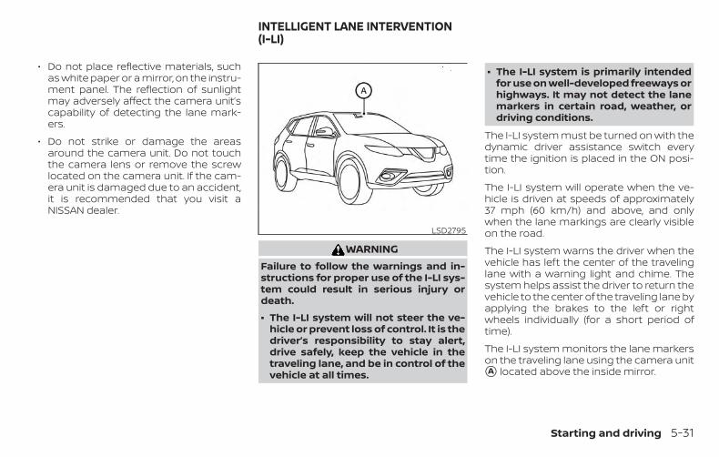
∙ Do not place reflective materials, suchas white paper or a mirror, on the instru-ment panel. The reflection of sunlightmay adversely affect the camera unit’scapability of detecting the lane mark-ers.
∙ Do not strike or damage the areasaround the camera unit. Do not touchthe camera lens or remove the screwlocated on the camera unit. If the cam-era unit is damaged due to an accident,it is recommended that you visit aNISSAN dealer.
WARNINGFailure to follow the warnings and in-structions for proper use of the I-LI sys-tem could result in serious injury ordeath.
∙ The I-LI system will not steer the ve-hicle or prevent loss of control. It is thedriver’s responsibility to stay alert,drive safely, keep the vehicle in thetraveling lane, and be in control of thevehicle at all times.
∙ The I-LI system is primarily intendedfor use on well-developed freeways orhighways. It may not detect the lanemarkers in certain road, weather, ordriving conditions.
The I-LI system must be turned on with thedynamic driver assistance switch everytime the ignition is placed in the ON posi-tion.
The I-LI system will operate when the ve-hicle is driven at speeds of approximately37 mph (60 km/h) and above, and onlywhen the lane markings are clearly visibleon the road.
The I-LI system warns the driver when thevehicle has left the center of the travelinglane with a warning light and chime. Thesystem helps assist the driver to return thevehicle to the center of the traveling lane byapplying the brakes to the left or rightwheels individually (for a short period oftime).
The I-LI system monitors the lane markerson the traveling lane using the camera unit�A located above the inside mirror.
LSD2795
INTELLIGENT LANE INTERVENTION(I-LI)
Starting and driving 5-31

�1 Dynamic driver assistance switch
�2 Lane Departure Warning (LDW) indica-tor
�3 Intelligent Lane Intervention (I-LI) indi-cator (if so equipped)
I-LI SYSTEM OPERATIONThe I-LI system operates above approxi-mately 37 mph (60 km/h). When the vehicleapproaches either the left or the right sideof the traveling lane, a warning chime willsound and the LDW indicator (orange) onthe instrument panel will blink to alert thedriver. Then, the I-LI system will automati-cally apply the brakes for a short period oftime to help assist the driver to return thevehicle to the center of the traveling lane.
To turn on the I-LI system, push the dy-namic driver assistance switch on the in-strument panel after starting the hybridsystem. The I-LI indicator on the instru-ment panel will illuminate. Push the dy-namic driver assistance switch again toturn off the I-LI system. The I-LI indicator willturn off.
LSD3315
5-32 Starting and driving

HOW TO ENABLE/DISABLE THE I-LISYSTEMPerform the following steps to enable ordisable the I-LI system.
1. Press the button until “Settings”displays in the vehicle information dis-play. Use the button to select“Driver Assistance.” Then press the OKbutton.
2. Select “Driving Aids” and press the OKbutton.
3. To set the I-LI system to on or off, usethe buttons to navigate in themenu and use the OK button to selector change an item:
∙ Select “Lane” and press the OK but-ton.
– To turn on the warning system, usethe OK button to check the box for“Prevention (LDP).”
4. Push the dynamic driver assistanceswitch to turn the system on or off.
LSD3093
Starting and driving 5-33

I-LI SYSTEM LIMITATIONS
WARNINGListed below are the system limitationsfor the I-LI system. Failure to follow thewarnings and instructions for properuse of the I-LI system could result inserious injury or death.
∙ The I-LI system may activate if youchange lanes without first activatingyour turn signal or, for example, if aconstruction zone directs traffic tocross an existing lane marker. If thisoccurs you may need to apply correc-tive steering to complete your lanechange.
∙ Because the I-LI may not activate un-der the road, weather, and lanemarker conditions described in thissection, it may not activate every timeyour vehicle begins to leave its laneand you will need to apply correctivesteering.
∙ When the I-LI system is operating,avoid excessive or sudden steeringmaneuvers. Otherwise, you could losecontrol of the vehicle.
∙ The I-LI system will not operate atspeeds below approximately 37 mph(60 km/h) or if it cannot detect lanemarkers.
∙ Do not use the I-LI system under thefollowing conditions as it may notfunction properly:
– During bad weather (rain, fog,snow, etc.).
– When driving on slippery roads,such as on ice or snow.
– When driving on winding or un-even roads.
– When there is a lane closure due toroad repairs.
– When driving in a makeshift ortemporary lane.
– When driving on roads where thelane width is too narrow.
– When driving without normal tireconditions (for example, tire wear,low tire pressure, installation ofspare tire, tire chains, non-standard wheels).
– When the vehicle is equipped withnonoriginal brake parts or suspen-sion parts.
– When you are towing a trailer orother vehicle.
– On roads where there are multipleparallel lane markers; lane mark-ers that are faded or not paintedclearly; yellow painted lane mark-ers; non-standard lane markers; orlane markers covered with water,dirt, snow, etc.
– On roads where discontinued lanemarkers are still detectable.
– On roads where there are sharpcurves.
– On roads where there are sharplycontrasting objects, such as shad-ows, snow, water, wheel ruts,seams or lines remaining afterroad repairs. (The I-LI system coulddetect these items as lanemarkers.)
– On roads where the traveling lanemerges or separates.
5-34 Starting and driving
– When the vehicle’s traveling direc-tion does not align with the lanemarker.
– When traveling close to the vehiclein front of you, which obstructs thelane camera unit detection range.
– When rain, snow or dirt adheres tothe windshield in front of the lanecamera unit.
– When the headlights are not brightdue to dirt on the lens or if the aim-ing is not adjusted properly.
– When strong light enters the lanecamera unit. (For example, the lightdirectly shines on the front of thevehicle at sunrise or sunset.)
– When a sudden change in bright-ness occurs. (For example, whenthe vehicle enters or exits a tunnelor under a bridge.)
∙ Excessive noise will interfere with thewarning chime sound, and the chimemay not be heard.
While the I-LI system is operating, you mayhear a sound of brake operation. This isnormal and indicates that the I-LI system isoperating properly.
SYSTEM TEMPORARILYUNAVAILABLECondition A:
The warning and assist functions of the I-LIsystem are not designed to work under thefollowing conditions:
∙ When you operate the lane change sig-nal and change the traveling lanes inthe direction of the signal. (The I-LI sys-tem will be deactivated for approxi-mately 2 seconds after the lane changesignal is turned off.)
∙ When the vehicle speed lowers to lessthan approximately 37 mph (60 km/h).
After the above conditions have finishedand the necessary operating conditionsare satisfied, the warning and assist func-tions will resume.
Condition B:
The assist function of the I-LI system is notdesigned to work under the following con-ditions (warning is still functional):
∙ When the brake pedal is depressed.
∙ When the steering wheel is turned as faras necessary for the vehicle to changelanes.
∙ When the vehicle is accelerated duringI-LI system operation.
∙ When the Intelligent Cruise Control (ICC)approach warning occurs.
∙ When the hazard warning flashers areoperated.
∙ When driving on a curve at high speed.
After the above conditions have finishedand the necessary operating conditionsare satisfied, the I-LI system application ofthe brakes will resume.
Condition C:
If the following messages appear in thevehicle information display, a chime willsound and the I-LI system will be turned offautomatically.
∙ “Unavailable: Road is slippery”:When the VDC system (except TractionControl System [TCS] function) or ABSoperates.
∙ “Unavailable: VDC OFF”:When the VDC system is turned off.
Starting and driving 5-35

Action to take:
When the above conditions no longer exist,turn off the I-LI system. Push the dynamicdriver assistance switch again to turn theI-LI system back on.
Temporary disabled status at high tem-perature:
If the vehicle is parked in direct sunlightunder high temperature conditions (overapproximately 104°F [40°C]) and then theI-LI system is turned on, the I-LI systemmay be deactivated automatically and thefollowing message will appear on the ve-hicle information display: “Unavailable: HighCabin Temp.” When the interior tempera-ture is reduced, the system will resume op-erating automatically.
SYSTEM MALFUNCTIONIf the I-LI system malfunctions, it will cancelautomatically. The I-LI system warning light(orange) will illuminate in the display.
If the I-LI system warning light (orange) illu-minates in the display, pull off the road to asafe location and stop the vehicle. Turn thehybrid system off and restart the hybridsystem. If the I-LI system warning light (or-ange) continues to illuminate, have the I-LIsystem checked. It is recommended thatyou visit a NISSAN dealer for this service.
SYSTEM MAINTENANCEThe lane camera unit �1 for the I-LI systemis located above the inside mirror. To keepthe proper operation of the I-LI system andprevent a system malfunction, be sure toobserve the following:
∙ Always keep the windshield clean.
∙ Do not attach a sticker (including trans-parent material) or install an accessorynear the camera unit.
LSD2712
5-36 Starting and driving

∙ Do not place reflective materials, suchas white paper or a mirror, on the instru-ment panel. The reflection of sunlightmay adversely affect the camera unit’scapability of detecting the lane mark-ers.
∙ Do not strike or damage the areasaround the camera unit. Do not touchthe camera lens or remove the screwlocated on the camera unit. If the cam-era unit is damaged due to an accident,it is recommended that you visit aNISSAN dealer.
WARNINGFailure to follow the warnings and in-structions for proper use of the BSWsystem could result in serious injury ordeath.
∙ The BSW system is not a replacementfor proper driving procedures and isnot designed to prevent contact withvehicles or objects. When changinglanes, always use the side and rearmirrors and turn and look in the direc-tion your vehicle will move to ensure itis safe to change lanes. Never relysolely on the BSW system.
The BSW system helps alert the driver ofother vehicles in adjacent lanes whenchanging lanes.
The BSW system uses radar sensors �1installed near the rear bumper to detectother vehicles in an adjacent lane.
LSD2439
BLIND SPOT WARNING (BSW)
Starting and driving 5-37

The radar sensors can detect vehicles oneither side of your vehicle within the detec-tion zone shown as illustrated. This detec-tion zone starts from the outside mirror ofyour vehicle and extends approximately10 ft (3.0 m) behind the rear bumper, andapproximately 10 ft (3.0 m) sideways.
Detection zoneSSD1030
LSD3306
5-38 Starting and driving

1. Side BSW/RCTA Indicator Light
2. BSW indicator
BSW SYSTEM OPERATIONThe BSW system operates above approxi-mately 20 mph (32 km/h).
If the radar sensors detect a vehicle in thedetection zone, the side BSW/RCTA indica-tor light (1) illuminates. If the turn signal isthen activated, the system chimes (twice),the side BSW/RCTA indicator light flashes,and the BSW indicator illuminates (yellow)in the vehicle information display. The sideBSW/RCTA indicator light continues toflash until the detected vehicle leaves thedetection zone.
The side BSW/RCTA indicator light illumi-nates for a few seconds when the ignitionswitch is placed in the ON position.
The brightness of the side BSW/RCTA indi-cator light is adjusted automatically de-pending on the brightness of the ambientlight.
If a vehicle comes into the detection zoneafter the driver activates the turn signal,then only the side BSW/RCTA indicator lightflashes and no chime sounds. For addi-tional information, refer to “BSW drivingsituations” in this section.
The BSW system automatically turns onevery time the hybrid system is started, aslong as it is activated using the settingsmenu on the vehicle information display.
Starting and driving 5-39

HOW TO ENABLE/DISABLE THEBSW SYSTEMPerform the following steps to enable ordisable the BSW system.
1. Press the button until “Settings”displays in the vehicle information dis-play. Use the button to select“Driver Assistance.” Then press the OKbutton.
2. Select “Driving Aids” and press the OKbutton.
3. Select “Blind Spot” and press the OKbutton.
– To turn on the warning system, usethe OK button to check the box for“Warning (BSW).”
NOTE:
When enabling/disabling the system,the system will retain current settingseven if the hybrid system is restarted.
LSD3095
5-40 Starting and driving

BSW SYSTEM LIMITATIONS
WARNINGListed below are the system limitationsfor the BSW system. Failure to operatethe vehicle in accordance with thesesystem limitations could result in seri-ous injury or death.
∙ The BSW system cannot detect all ve-hicles under all conditions.
∙ The radar sensors may not be able todetect and activate BSW when certainobjects are present such as:
– Pedestrian, bicycles, animals.
– Vehicles such as motorcycles, lowheight vehicles, or high groundclearance vehicles.
– Oncoming vehicles.
– Vehicles remaining in the detec-tion zone when you acceleratefrom a stop.
– A vehicle merging into an adjacentlane at a speed approximately thesame as your vehicle.
– A vehicle approaching rapidly frombehind.
– A vehicle which your vehicle over-takes rapidly.
– A vehicle that passes through thedetection zone quickly.
– When overtaking several vehiclesin a row, the vehicles after the firstvehicle may not be detected if theyare traveling close together.
∙ The radar sensors’ detection zone isdesigned based on a standard lanewidth. When driving in a wider lane,the radar sensors may not detect ve-hicles in an adjacent lane. When driv-ing in a narrow lane, the radar sensorsmay detect vehicles driving two lanesaway.
∙ The radar sensors are designed to ig-nore most stationary objects; how-ever, objects such as guardrails, walls,foliage and parked vehicles may oc-casionally be detected. This is a nor-mal operation condition.
∙ The following conditions may reducethe ability of the radar to detect othervehicles:
– Severe weather
– Road spray
– Ice/frost/snow/dirt build-up onthe vehicle
∙ Do not attach stickers (includingtransparent material), install accesso-ries or apply additional paint near theradar sensors. These conditions mayreduce the ability of the radar to de-tect other vehicles.
∙ Excessive noise (for example, audiosystem volume, open vehicle window)will interfere with the chime sound,and it may not be heard.
Starting and driving 5-41

BSW DRIVING SITUATIONSIndicator on
Indicator off
Indicator flashing
Another vehicle approachingfrom behindIllustration 1: The side BSW/RCTA indicatorlight illuminates if a vehicle enters the de-tection zone from behind in an adjacentlane.
Illustration 2: If the driver activates theturn signal when another vehicle is in thedetection zone, then the system chimes(twice) and the side indicator light flashes.
NOTE:
∙ The radar sensors may not detect ve-hicles which are approaching rapidlyfrom behind.
∙ If the driver activates the turn signalbefore a vehicle enters the detectionzone, the side indicator light will flashbut no chime will sound when theother vehicle is detected.
Illustration 1 – Approaching from behindLSD2299
Illustration 2 – Approaching from behindLSD2300
5-42 Starting and driving

Overtaking another vehicleIllustration 3: The side indicator light illu-minates if you overtake a vehicle and thatvehicle stays in the detection zone for ap-proximately 2 seconds.
Illustration 4: If the driver activates theturn signal while another vehicle is in thedetection zone, then the system chimes(twice) and the side indicator light flashes.
NOTE:
∙ When overtaking several vehicles in arow, the vehicles after the first vehiclemay not be detected if they are trav-eling close together.
∙ The radar sensors may not detectslower moving vehicles if they arepassed quickly.
∙ If the driver activates the turn signalbefore a vehicle enters the detectionzone, the side indicator light will flashbut no chime will sound when theother vehicle is detected. .
Illustration 3 – Overtaking anothervehicle
LSD2302Illustration 4 – Overtaking another
vehicle
LSD2303
Starting and driving 5-43

Entering from the sideIllustration 5: The side indicator light illu-minates if a vehicle enters the detectionzone from either side.
Illustration 6: If the driver activates theturn signal while another vehicle is in thedetection zone, then the system chimes(twice) and the side indicator light flashes.
NOTE:
∙ If the driver activates the turn signalbefore a vehicle enters the detectionzone, the side indicator light will flashbut no chime will sound when theother vehicle is detected.
∙ The radar sensors may not detect avehicle which is traveling at about thesame speed as your vehicle when itenters the detection zone.
Illustration 5 – Entering from the sideLSD2305
Illustration 6 – Entering from the sideLSD2308
5-44 Starting and driving

SYSTEM TEMPORARILYUNAVAILABLEWhen radar blockage is detected, the sys-tem will be deactivated automatically. The“Side Radar Obstruction” warning messagewill appear in the vehicle information dis-play.
The system is not available until the condi-tions no longer exist.
The radar sensors may be blocked by tem-porary ambient conditions such as splash-ing water, mist or fog. The blocked condi-tion may also be caused by objects such asice, frost or dirt obstructing the radar sen-sors.
NOTE:
If the BSW system stops working, theRCTA system will also stop working.
Action to take:
When the above conditions no longer exist,the system will resume automatically.
LSD2735
Starting and driving 5-45
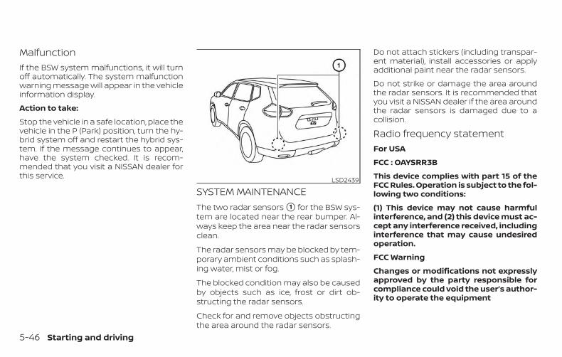
MalfunctionIf the BSW system malfunctions, it will turnoff automatically. The system malfunctionwarning message will appear in the vehicleinformation display.
Action to take:
Stop the vehicle in a safe location, place thevehicle in the P (Park) position, turn the hy-brid system off and restart the hybrid sys-tem. If the message continues to appear,have the system checked. It is recom-mended that you visit a NISSAN dealer forthis service.
SYSTEM MAINTENANCEThe two radar sensors �1 for the BSW sys-tem are located near the rear bumper. Al-ways keep the area near the radar sensorsclean.
The radar sensors may be blocked by tem-porary ambient conditions such as splash-ing water, mist or fog.
The blocked condition may also be causedby objects such as ice, frost or dirt ob-structing the radar sensors.
Check for and remove objects obstructingthe area around the radar sensors.
Do not attach stickers (including transpar-ent material), install accessories or applyadditional paint near the radar sensors.
Do not strike or damage the area aroundthe radar sensors. It is recommended thatyou visit a NISSAN dealer if the area aroundthe radar sensors is damaged due to acollision.
Radio frequency statementFor USA
FCC : OAYSRR3B
This device complies with part 15 of theFCC Rules. Operation is subject to the fol-lowing two conditions:
(1) This device may not cause harmfulinterference, and (2) this device must ac-cept any interference received, includinginterference that may cause undesiredoperation.
FCC Warning
Changes or modifications not expresslyapproved by the party responsible forcompliance could void the user’s author-ity to operate the equipment
LSD2439
5-46 Starting and driving
For Canada
Applicable law: Canada 310
This device complies with IndustryCanada licence-exempt RSS standard(s).Operation is subject to the following twoconditions: (1) this device may not causeinterference, and (2) this device must ac-cept any interference, including interfer-ence that may cause undesired opera-tion of the device.
Frequency bands: 24.05 – 24.25GHz
Output power: less than 20 milliwatts
WARNINGFailure to follow the warnings and in-structions for proper use of the RCTAsystem could result in serious injury ordeath.
∙ The RCTA system is not a replacementfor proper driving procedures and isnot designed to prevent contact withvehicles or objects. When backing outof a parking space, always use theside and rear mirrors and turn andlook in the direction your vehicle willmove. Never rely solely on the RCTAsystem.
The RCTA system will assist you whenbacking out from a parking space. Whenthe vehicle is in reverse, the system is de-signed to detect other vehicles approach-ing from the right or left of the vehicle. If thesystem detects cross traffic, it will alert you.
REAR CROSS TRAFFIC ALERT (RCTA)
Starting and driving 5-47

1. Side BSW/RCTA Indicator Light
RCTA SYSTEM OPERATIONThe RCTA system can help alert the driverof an approaching vehicle when the driveris backing out of a parking space.
When the shift position is in R (Reverse) andthe vehicle speed is less than approxi-mately 5 mph (8 km/h), the RCTA system isoperational.
If the radar detects an approaching vehiclefrom either side, the system chimes (once)and the side BSW/RCTA indicator lightflashes on the side the vehicle is approach-ing from.
LSD2734
5-48 Starting and driving
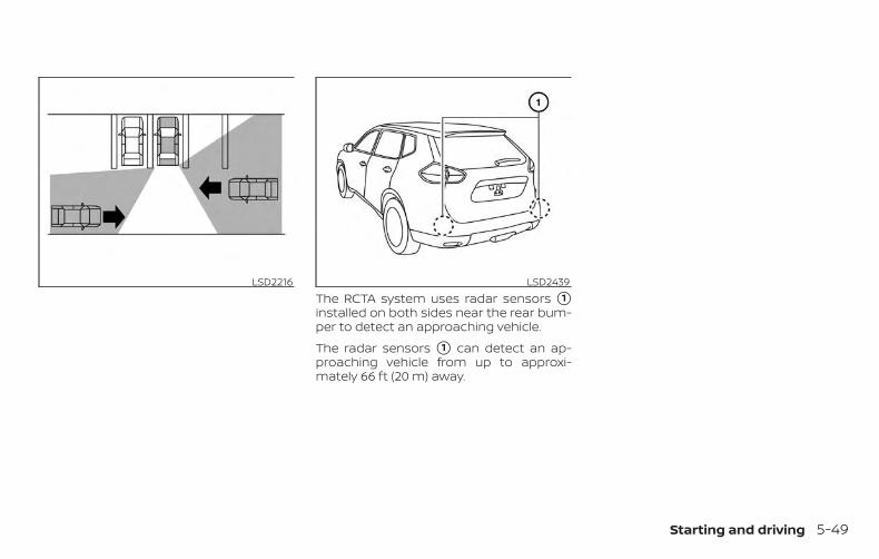
The RCTA system uses radar sensors �1installed on both sides near the rear bum-per to detect an approaching vehicle.
The radar sensors �1 can detect an ap-proaching vehicle from up to approxi-mately 66 ft (20 m) away.
LSD2216 LSD2439
Starting and driving 5-49

HOW TO ENABLE/DISABLE THERCTA SYSTEMPerform the following steps to enable ordisable the RCTA system.
1. Press the button until “Settings”displays in the vehicle information dis-play. Use the button to select“Driver Assistance.” Then press the OKbutton.
2. Select “Parking Aids” and press the OKbutton.
3. Select “Cross Traffic” and press the OKbutton.
4. Use the OK button to enable or disablethe system.
NOTE:
When enabling/disabling the system,the system setting will be retained evenif the hybrid system is restarted.
LSD2768
5-50 Starting and driving
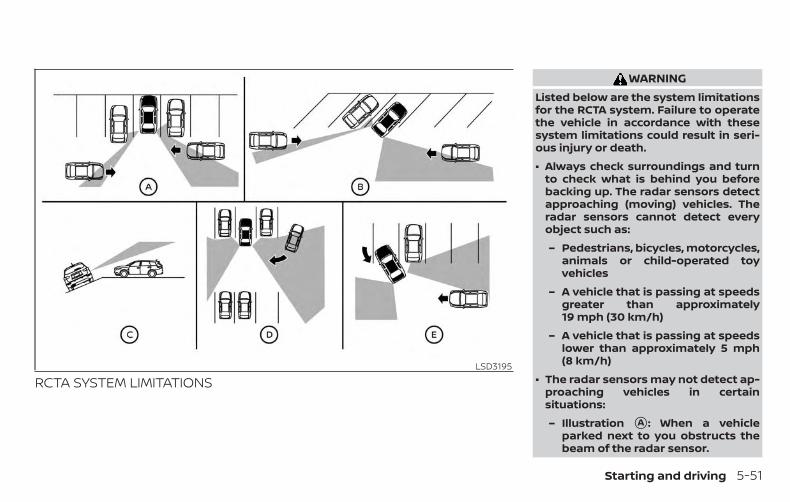
RCTA SYSTEM LIMITATIONS
WARNINGListed below are the system limitationsfor the RCTA system. Failure to operatethe vehicle in accordance with thesesystem limitations could result in seri-ous injury or death.
∙ Always check surroundings and turnto check what is behind you beforebacking up. The radar sensors detectapproaching (moving) vehicles. Theradar sensors cannot detect everyobject such as:
– Pedestrians, bicycles, motorcycles,animals or child-operated toyvehicles
– A vehicle that is passing at speedsgreater than approximately19 mph (30 km/h)
– A vehicle that is passing at speedslower than approximately 5 mph(8 km/h)
∙ The radar sensors may not detect ap-proaching vehicles in certainsituations:
– Illustration �A : When a vehicleparked next to you obstructs thebeam of the radar sensor.
LSD3195
Starting and driving 5-51
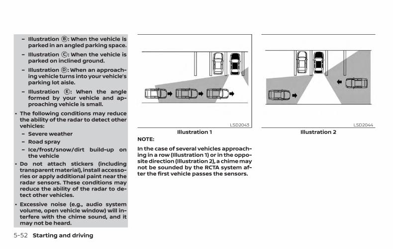
– Illustration �B : When the vehicle isparked in an angled parking space.
– Illustration �C : When the vehicle isparked on inclined ground.
– Illustration �D : When an approach-ing vehicle turns into your vehicle’sparking lot aisle.
– Illustration �E : When the angleformed by your vehicle and ap-proaching vehicle is small.
∙ The following conditions may reducethe ability of the radar to detect othervehicles:– Severe weather– Road spray– Ice/frost/snow/dirt build-up on
the vehicle∙ Do not attach stickers (including
transparent material), install accesso-ries or apply additional paint near theradar sensors. These conditions mayreduce the ability of the radar to de-tect other vehicles.
∙ Excessive noise (e.g., audio systemvolume, open vehicle window) will in-terfere with the chime sound, and itmay not be heard.
NOTE:
In the case of several vehicles approach-ing in a row (Illustration 1) or in the oppo-site direction (Illustration 2), a chime maynot be sounded by the RCTA system af-ter the first vehicle passes the sensors.
Illustration 1LSD2043
Illustration 2LSD2044
5-52 Starting and driving
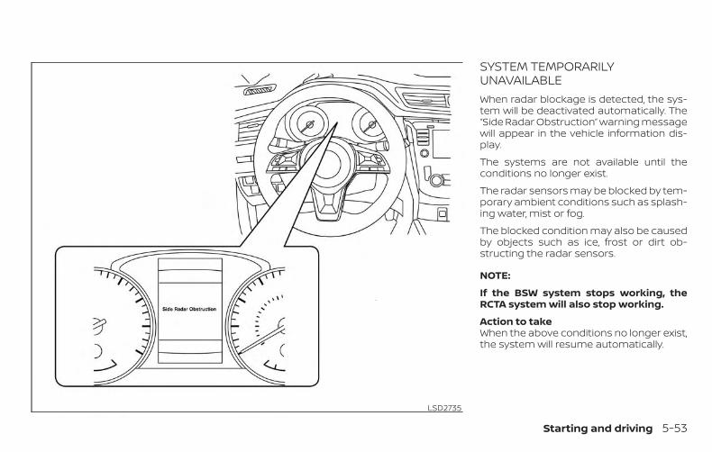
SYSTEM TEMPORARILYUNAVAILABLEWhen radar blockage is detected, the sys-tem will be deactivated automatically. The“Side Radar Obstruction” warning messagewill appear in the vehicle information dis-play.
The systems are not available until theconditions no longer exist.
The radar sensors may be blocked by tem-porary ambient conditions such as splash-ing water, mist or fog.
The blocked condition may also be causedby objects such as ice, frost or dirt ob-structing the radar sensors.
NOTE:
If the BSW system stops working, theRCTA system will also stop working.
Action to takeWhen the above conditions no longer exist,the system will resume automatically.
LSD2735
Starting and driving 5-53
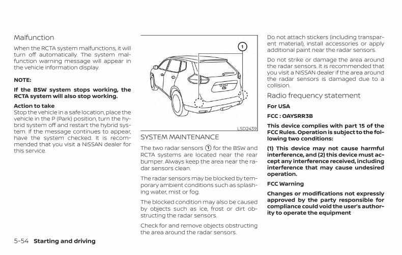
MalfunctionWhen the RCTA system malfunctions, it willturn off automatically. The system mal-function warning message will appear inthe vehicle information display.
NOTE:
If the BSW system stops working, theRCTA system will also stop working.
Action to takeStop the vehicle in a safe location, place thevehicle in the P (Park) position, turn the hy-brid system off and restart the hybrid sys-tem. If the message continues to appear,have the system checked. It is recom-mended that you visit a NISSAN dealer forthis service.
SYSTEM MAINTENANCEThe two radar sensors �1 for the BSW andRCTA systems are located near the rearbumper. Always keep the area near the ra-dar sensors clean.
The radar sensors may be blocked by tem-porary ambient conditions such as splash-ing water, mist or fog.
The blocked condition may also be causedby objects such as ice, frost or dirt ob-structing the radar sensors.
Check for and remove objects obstructingthe area around the radar sensors.
Do not attach stickers (including transpar-ent material), install accessories or applyadditional paint near the radar sensors.
Do not strike or damage the area aroundthe radar sensors. It is recommended thatyou visit a NISSAN dealer if the area aroundthe radar sensors is damaged due to acollision.
Radio frequency statementFor USA
FCC : OAYSRR3B
This device complies with part 15 of theFCC Rules. Operation is subject to the fol-lowing two conditions:
(1) This device may not cause harmfulinterference, and (2) this device must ac-cept any interference received, includinginterference that may cause undesiredoperation.
FCC Warning
Changes or modifications not expresslyapproved by the party responsible forcompliance could void the user’s author-ity to operate the equipment
LSD2439
5-54 Starting and driving

For Canada
Applicable law: Canada 310
This device complies with IndustryCanada licence-exempt RSS standard(s).Operation is subject to the following twoconditions: (1) this device may not causeinterference, and (2) this device must ac-cept any interference, including interfer-ence that may cause undesired opera-tion of the device.
Frequency bands: 24.05 – 24.25GHz
Output power: less than 20 milliwatts
PRECAUTIONS ON CRUISECONTROL
�1 RES+ switch
�2 CANCEL switch
�3 SET- switch
�4 Cruise control switch
∙ If the cruise control system malfunc-tions, it cancels automatically. Theindicator in the vehicle information dis-play then blinks to warn the driver.
∙ If the indicator blinks, turn thecruise control switch off and have thesystem checked. It is recommendedthat you visit a NISSAN dealer for thisservice.
∙ The indicator may blink when thecruise control switch is turned on whilepushing the RES+, SET-, or CANCELswitch. To properly set the cruise con-trol system, use the following proce-dures.
WARNINGDo not use the cruise control when driv-ing under the following conditions:
∙ When it is not possible to keep thevehicle at a set speed.
∙ In heavy traffic or in traffic that variesin speed.
∙ On winding or hilly roads.
∙ On slippery roads (rain, snow, ice, etc.).
∙ In very windy areas.
Doing so could cause a loss of vehiclecontrol and result in an accident.
LSD3251
CRUISE CONTROL (if so equipped)
Starting and driving 5-55
CRUISE CONTROL OPERATIONSThe cruise control allows driving at a speedbetween 25 - 89 mph (40 - 144 km/h) with-out keeping your foot on the acceleratorpedal.
To turn on the cruise control, push thecruise control switch on. The indica-tor in the vehicle information display willilluminate.To set cruising speed, accelerate the ve-hicle to the desired speed, push the SET-switch and release it. Take your foot off theaccelerator pedal. Your vehicle maintainsthe set speed.
∙ To pass another vehicle, depress theaccelerator pedal. When you release thepedal, the vehicle returns to the previ-ously set speed.
∙ The vehicle may not maintain the setspeed when going up or down steephills. If this happens, drive without thecruise control.
To cancel the preset speed, use one of thefollowing three methods:
∙ Push the CANCEL switch.
∙ Tap the brake pedal.
∙ Push the cruise control switch off.The indicator in the vehicle infor-mation display goes out.
The cruise control is automatically can-celed if:
∙ You depress the brake pedal whilepushing the RES+ or SET- switch. Thepreset speed is deleted from memory.
∙ The vehicle slows down more than8 mph (13 km/h) below the set speed.
∙ You move the shift lever to N (Neutral).
To reset at a faster cruising speed, useone of the following three methods:
∙ Depress the accelerator pedal. Whenthe vehicle attains the desired speed,push and release the SET- switch.
∙ Push and hold the RES+ switch. Whenthe vehicle attains the speed you desire,release the switch.
∙ Push and release the RES+ switch. Eachtime you do this, the set speed in-creases by about 1 mph (1.6 km/h).
To reset at a slower cruising speed, useone of the following three methods:
∙ Lightly tap the brake pedal. When thevehicle attains the desired speed, pushthe SET- switch and release it.
∙ Push and hold the SET- switch. Releasethe switch when the vehicle slows tothe desired speed.
∙ Push and release the SET- switch. Eachtime you do this, the set speed de-creases by about 1 mph (1.6 km/h).
To resume the preset speed, push andrelease the RES+ switch. The vehicle re-turns to the last set cruising speed whenthe vehicle speed is over 25 mph (40 km/h).
To turn off the cruise control, use one ofthe following three methods:
∙ Push the CANCEL switch.
∙ Tap the brake pedal.
∙ Push the cruise control switch off.The indicator in the vehicle infor-mation display goes out.
5-56 Starting and driving

�A ICC switch
WARNINGFailure to follow the warnings and in-structions for proper use of the ICC sys-tem could result in serious injury ordeath.
∙ The ICC system is only an aid to assistthe driver and is not a collision warn-ing or avoidance device. It is the driv-er’s responsibility to stay alert, drivesafely, and be in control of the vehicleat all times.
∙ Always observe posted speed limitsand do not set the speed over them.
∙ Always drive carefully and attentivelywhen using the ICC system. Read andunderstand the Owner’s Manual thor-oughly before using the ICC system.To avoid serious injury or death, donot rely on the system to prevent ac-cidents or to control the vehicle’sspeed in emergency situations. Donot use the ICC system except in ap-propriate road and traffic conditions.
LSD3096
INTELLIGENT CRUISE CONTROL (ICC)(if so equipped)
Starting and driving 5-57

∙ In the conventional (fixed speed)cruise control mode, a warning chimewill not sound to warn you if you aretoo close to the vehicle ahead. Payspecial attention to the distance be-tween your vehicle and the vehicleahead of you or a collision could occur.
The ICC system maintains a selected dis-tance from the vehicle in front of you withinthe speed range of 0 to 90 mph (0 to144 km/h) up to the set speed. The setspeed can be selected by the driver be-tween 20 to 90 mph (32 to 144 km/h).
The vehicle travels at a set speed when theroad ahead is clear.
The ICC system can be set to one of twocruise control modes:
∙ Vehicle-to-vehicle distance controlmode: For maintaining a selected dis-tance between your vehicle and the ve-hicle in front of you up to the presetspeed
∙ Conventional (fixed speed) cruisecontrol mode: For cruising at a presetspeed
Push the ICC switch �A to choose thecruise control mode between the vehicle-to-vehicle distance control mode and theconventional (fixed speed) cruise controlmode.
Once a control mode is activated, it cannotbe changed to the other cruise controlmode. To change the mode, push the ICCswitch �A once to turn the system off. Thenpush the ICC switch �A again to turn thesystem back on and select the desiredcruise control mode.
Always confirm the setting in the ICC sys-tem display.
For the vehicle-to-vehicle distance controlmode, refer to “Vehicle-to-vehicle distancecontrol mode” in this section.
For the conventional (fixed speed) cruisecontrol mode, refer to “Conventional (fixedspeed) cruise control mode” in this section.
5-58 Starting and driving
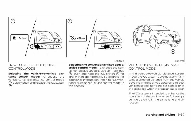
HOW TO SELECT THE CRUISECONTROL MODESelecting the vehicle-to-vehicle dis-tance control mode: To choose thevehicle-to-vehicle distance control mode�1 , quickly push and release the ICC switch�A .
Selecting the conventional (fixed speed)cruise control mode: To choose the con-ventional (fixed speed) cruise control mode�2 , push and hold the ICC switch �A forlonger than approximately 1.5 seconds. Foradditional information, refer to “Conven-tional (fixed speed) cruise control mode” inthis section.
VEHICLE-TO-VEHICLE DISTANCECONTROL MODEIn the vehicle-to-vehicle distance controlmode, the ICC system automatically main-tains a selected distance from the vehicletraveling in front of you according to thatvehicle’s speed (up to the set speed), or atthe set speed when the road ahead is clear.
The ICC system is intended to enhance theoperation of the vehicle when following avehicle traveling in the same lane and di-rection.
LSD3269 LSD2731
Starting and driving 5-59
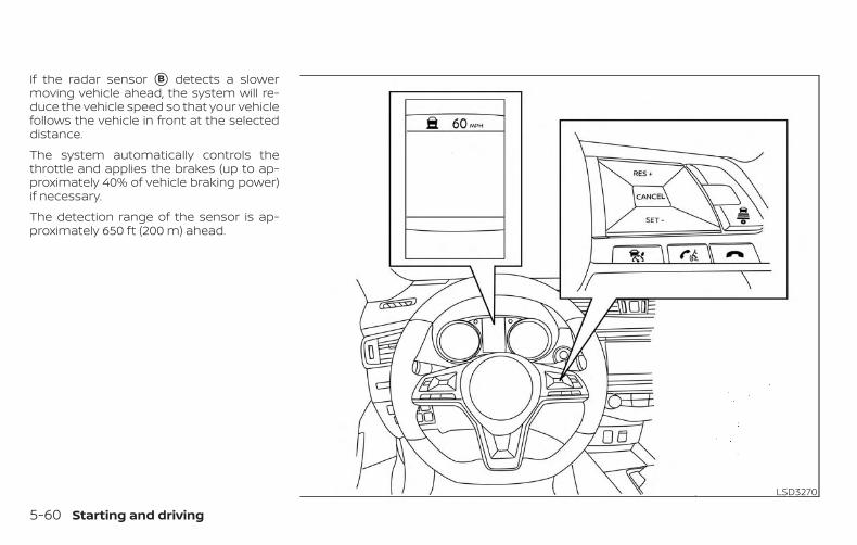
If the radar sensor �B detects a slowermoving vehicle ahead, the system will re-duce the vehicle speed so that your vehiclefollows the vehicle in front at the selecteddistance.
The system automatically controls thethrottle and applies the brakes (up to ap-proximately 40% of vehicle braking power)if necessary.
The detection range of the sensor is ap-proximately 650 ft (200 m) ahead.
LSD3270
5-60 Starting and driving

VEHICLE-TO-VEHICLE DISTANCECONTROL MODE OPERATIONThe vehicle-to-vehicle distance controlmode is designed to maintain a selecteddistance from the vehicle in front of youand can reduce the speed to match aslower vehicle ahead. The system will de-celerate the vehicle as necessary and if thevehicle ahead comes to a stop, the vehicledecelerates to a standstill. However, the ICCsystem can only apply up to 40% of thevehicle’s total braking power.
This system should only be used when traf-fic conditions allow vehicle speeds to re-main fairly constant or when vehiclespeeds change gradually. If a vehiclemoves into the traveling lane ahead or if avehicle traveling ahead rapidly decelerates,the distance between vehicles may be-come closer because the ICC system can-not decelerate the vehicle quickly enough.If this occurs, the ICC system will sound awarning chime and blink the system dis-play to notify the driver to take necessaryaction.
The system will cancel and a warningchime will sound if the speed is below ap-proximately 15 mph (24 km/h) and a vehicleis not detected ahead. The system will also
disengage when the vehicle goes abovethe maximum set speed.
For additional information, refer to “Ap-proach warning” in this section.
The following items are controlled in thevehicle-to-vehicle distance control mode:
∙ When there are no vehicles travelingahead, the vehicle-to-vehicle distancecontrol mode maintains the speed setby the driver. The set speed range isbetween approximately 20 and 90 mph(32 and 144 km/h).
∙ When there is a vehicle traveling ahead,the vehicle-to-vehicle distance controlmode adjusts the speed to maintainthe distance, selected by the driver,from the vehicle ahead. If the vehicleahead comes to a stop, the vehicle de-celerates to a standstill within the limi-tations of the system. The system willcancel once it judges a standstill with awarning chime.
∙ When the vehicle traveling ahead hasmoved out from its lane of travel, thevehicle-to-vehicle distance controlmode accelerates and maintains ve-hicle speed up to the set speed.
The ICC system does not control vehiclespeed or warn you when you approachstationary and slow moving vehicles. Youmust pay attention to vehicle operation tomaintain proper distance from vehiclesahead when approaching toll gates or traf-fic congestion.
Starting and driving 5-61

When driving on the freeway at a set speedand approaching a slower traveling vehicleahead, the ICC system will adjust the speedto maintain the distance, selected by thedriver, from the vehicle ahead. If the vehicleahead changes lanes or exits the freeway,the ICC system will accelerate and main-tain the speed up to the set speed. Payattention to the driving operation to main-tain control of the vehicle as it acceleratesto the set speed.
The vehicle may not maintain the setspeed on winding or hilly roads. If this oc-curs, you will have to manually control thevehicle speed.
Normally when controlling the distance toa vehicle ahead, this system automaticallyaccelerates or decelerates your vehicle ac-cording to the speed of the vehicle ahead.Depress the accelerator to properly accel-erate your vehicle when acceleration is re-quired for a lane change. Depress the brakepedal when deceleration is required tomaintain a safe distance to the vehicleahead due to its sudden braking or if avehicle cuts in. Always stay alert when us-ing the ICC system.
VEHICLE-TO-VEHICLE DISTANCECONTROL MODE SWITCHESThe system is operated by the ICC switchand four control switches, all mounted onthe steering wheel.
1. CANCEL switch:
Deactivates the system without eras-ing the set speed.
2. RES+ switch:
Resumes set speed or increasesspeed incrementally.
SSD0254 LSD3265
5-62 Starting and driving
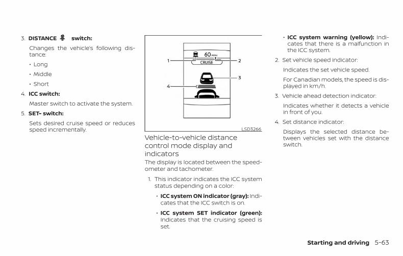
3. DISTANCE switch:
Changes the vehicle’s following dis-tance:
∙ Long
∙ Middle
∙ Short
4. ICC switch:
Master switch to activate the system.
5. SET- switch:
Sets desired cruise speed or reducesspeed incrementally.
Vehicle-to-vehicle distancecontrol mode display andindicatorsThe display is located between the speed-ometer and tachometer.
1. This indicator indicates the ICC systemstatus depending on a color:
∙ ICC system ON indicator (gray): Indi-cates that the ICC switch is on.
∙ ICC system SET indicator (green):Indicates that the cruising speed isset.
∙ ICC system warning (yellow): Indi-cates that there is a malfunction inthe ICC system.
2. Set vehicle speed indicator:
Indicates the set vehicle speed.
For Canadian models, the speed is dis-played in km/h.
3. Vehicle ahead detection indicator:
Indicates whether it detects a vehiclein front of you.
4. Set distance indicator:
Displays the selected distance be-tween vehicles set with the distanceswitch.
LSD3266
Starting and driving 5-63

Operating vehicle-to-vehicledistance control modeTo turn on the cruise control, quickly pushand release the ICC switch �A . The ICC sys-tem ON indicator (gray), set distance indi-cator and set vehicle speed indicator �Bcome on in a standby state for setting.
To set cruising speed, accelerate your ve-hicle to the desired speed, push the SET–switch �C and release it. The ICC system setindicator (green), vehicle ahead detectionindicator, set distance indicator and set ve-hicle speed indicator �B will come on. Takeyour foot off the accelerator pedal. Yourvehicle will maintain the set speed.
When the SET– switch is pushed under thefollowing conditions, the system cannot beset and the ICC indicators will blink for ap-proximately 2 seconds:
∙ When traveling below 20 mph (32 km/h)and a vehicle ahead is not detected
∙ When the shift lever is not in the D (Drive)or Manual mode
∙ When the parking brake is applied
∙ When the brakes are operated by thedriver
LSD3100 LSD3101 LSD3102
5-64 Starting and driving
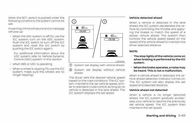
When the SET– switch is pushed under thefollowing conditions, the system cannot beset.
A warning chime will sound and a messagewill pop up:
∙ When the VDC system is off (To use theICC system, turn on the VDC system.Push the ICC switch to turn off the ICCsystem and reset the ICC switch bypushing the ICC switch again.)
For additional information about theVDC system, refer to “Vehicle DynamicControl (VDC) system” in this section.
∙ When ABS or VDC is operating
∙ When a wheel is slipping (To use the ICCsystem, make sure the wheels are nolonger slipping.)
�1 System set display with vehicle ahead
�2 System set display without vehicleahead
The driver sets the desired vehicle speedbased on the road conditions. The ICC sys-tem maintains the set vehicle speed, simi-lar to standard cruise control, as long as novehicle is detected in the lane ahead. TheICC system displays the set speed.
Vehicle detected ahead
When a vehicle is detected in the laneahead, the ICC system decelerates the ve-hicle by controlling the throttle and apply-ing the brakes to match the speed of aslower vehicle ahead. The system thencontrols the vehicle speed based on thespeed of the vehicle ahead to maintain thedriver selected distance.
NOTE:
∙ The stop lights of the vehicle come onwhen braking is performed by the ICCsystem.
∙ When the brake operates, a noise maybe heard. This is not a malfunction.
When a vehicle ahead is detected, the ve-hicle ahead detection indicator comes on.The ICC system will also display the setspeed and selected distance.
Vehicle ahead not detected
When a vehicle is no longer detectedahead, the ICC system gradually acceler-ates your vehicle to resume the previouslyset vehicle speed. The ICC system thenmaintains the set speed.
LSD3103
Starting and driving 5-65

When a vehicle is no longer detected, thevehicle ahead detection indicator turns off.
If a vehicle ahead appears during accelera-tion to the set vehicle speed or any time theICC system is in operation, the system con-trols the distance to that vehicle.
When a vehicle is no longer detected underapproximately 15 mph (24 km/h), the sys-tem will be canceled.
When passing another vehicle, the setspeed indicator �A will flash when the ve-hicle speed exceeds the set speed. The ve-hicle detect indicator will turn off when thearea ahead of the vehicle is open. When thepedal is released, the vehicle will return tothe previously set speed.
Even though your vehicle speed is set in theICC system, you can depress the accelera-tor pedal when it is necessary to accelerateyour vehicle rapidly.
How to change the set vehiclespeedTo cancel the preset speed, use one of thefollowing methods:
∙ Push the CANCEL switch. The set ve-hicle speed indicator will go out.
∙ Tap the brake pedal. The set vehiclespeed indicator will go out.
∙ Turn the ICC switch off. The ICC indica-tors will go out.
To reset at a faster cruising speed, useone of the following methods:
∙ Depress the accelerator pedal. Whenthe vehicle attains the desired speed,push and release the SET– switch.
∙ Push and hold the RES+ switch. The setvehicle speed will increase by approxi-mately 5 mph (5 km/h).
∙ Push, then quickly release the RES+switch. Each time you do this, the setspeed will increase by approximately1 mph (1 km/h).
LSD3267
5-66 Starting and driving

To reset at a slower cruising speed, useone of the following methods:
∙ Lightly tap the brake pedal. When thevehicle attains the desired speed, pushthe SET– switch and release it.
∙ Push and hold the SET– switch. The setvehicle speed will decrease by approxi-mately 5 mph (5 km/h).
∙ Push, then quickly release the SET–switch. Each time you do this, the setspeed will decrease by approximately1 mph (1 km/h).
To resume the preset speed, push andrelease the RES+ switch. The vehicle willresume the last set cruising speed whenthe vehicle speed is over 20 mph (32 km/h).
How to change the set distanceto the vehicle aheadThe distance to the vehicle ahead can beselected at any time depending on the traf-fic conditions.
Each time the distance switch �A ispushed, the set distance will change tolong, middle, short and back to long again,in that sequence.
Distance Approximate distance at60 mph (100 km/h) [ft (m)]
1. Long 200 (60)2. Middle 150 (45)3. Short 100 (30)
∙ The distance to the vehicle ahead willchange according to the vehicle speed.The higher the vehicle speed, the longerthe distance.
∙ If the hybrid system is stopped, the setdistance becomes “long.” (Each time thehybrid system is started, the initial set-ting becomes “long.”)
LSD2683 LSD2429
Starting and driving 5-67

Approach warningIf your vehicle comes closer to the vehicleahead due to rapid deceleration of that ve-hicle or if another vehicle cuts in, the sys-tem warns the driver with the chime andICC system display. Decelerate by depress-ing the brake pedal to maintain a safe ve-hicle distance if:
∙ The chime sounds.
∙ The vehicle ahead detection indicatorblinks.
The warning chime may not sound insome cases when there is a short distancebetween vehicles. Some examples are:
∙ When the vehicles are traveling at thesame speed and the distance betweenvehicles is not changing.
∙ When the vehicle ahead is travelingfaster and the distance between ve-hicles is increasing.
∙ When a vehicle cuts in near your vehicle.
The warning chime will not sound when:
∙ The vehicle approaches other vehiclesthat are parked or moving slowly.
∙ The accelerator pedal is depressed,overriding the system.
NOTE:
The approach warning chime may soundand the system display may blink whenthe ICC sensor detects objects on theside of the vehicle or on the side of theroad. This may cause the ICC system todecelerate or accelerate the vehicle. TheICC sensor may detect these objectswhen the vehicle is driven on windingroads, narrow roads, hilly roads, or whenentering or exiting a curve. In thesecases you will have to manually controlthe proper distance ahead of your ve-hicle.
Also, the sensor sensitivity can be affectedby vehicle operation (steering maneuver ordriving position in the lane) or traffic or ve-hicle condition (for example, if a vehicle isbeing driven with some damage).
Automatic cancellationA chime sounds under the following condi-tions and the control is automatically can-celed:
∙ When the vehicle ahead is not detectedand your vehicle is traveling below thespeed of 15 mph (24 km/h)
∙ When the system judges the vehicle isat a standstill
∙ When the shift lever is not in the D (Drive)position or Manual mode
∙ When the parking brake system is ap-plied
∙ When the VDC system is turned off
∙ When VDC operates
∙ When distance measurement be-comes impaired due to adhesion of dirtor obstruction to the sensor
∙ When a wheel slips
∙ When the radar signal is temporarily in-terrupted
5-68 Starting and driving

VEHICLE-TO-VEHICLE DISTANCECONTROL MODE LIMITATIONS
WARNINGListed below are the system limitationsfor the ICC system. Failure to operatethe vehicle in accordance with thesesystem limitations could result in seri-ous injury or death.
∙ The ICC system is primarily intendedfor use on straight, dry, open roadswith light traffic. It is not advisable touse the ICC system in city traffic orcongested areas.
∙ The ICC system will not adapt auto-matically to road conditions. This sys-tem should be used in evenly flowingtraffic. Do not use the system on roadswith sharp curves, or on icy roads, inheavy rain or in fog.
∙ As there is a performance limit to thedistance control function, never relysolely on the ICC system. This systemdoes not correct careless, inattentiveor absentminded driving, or over-come poor visibility in rain, fog, orother bad weather. Decelerate the ve-hicle speed by depressing the brakepedal, depending on the distance tothe vehicle ahead and the surround-ing circumstances in order to main-tain a safe distance between vehicles.
∙ If the vehicle ahead comes to a stop,the vehicle decelerates to a standstillwithin the limitations of the system.The system will cancel once it judgesthat the vehicle has come to a stand-still and sound a warning chime. Toprevent the vehicle from moving, thedriver must depress the brake pedal.
∙ Always pay attention to the operationof the vehicle and be ready to manu-ally control the proper following dis-tance. The ICC system may not be ableto maintain the selected distance be-tween vehicles (following distance) orselected vehicle speed under somecircumstances.
∙ The system may not detect the ve-hicle in front of you in certain road orweather conditions. To avoid acci-dents, never use the ICC system underthe following conditions:
– On roads where the traffic is heavyor there are sharp curves
– On slippery road surfaces such ason ice or snow, etc.
– During bad weather (rain, fog,snow, etc.)
– When rain, snow or dirt adhere to thebumper around the distance sensor
– On steep downhill roads (the ve-hicle may go beyond the set ve-hicle speed and frequent brakingmay result in overheating thebrakes)
– On repeated uphill and downhillroads
– When traffic conditions make it dif-ficult to keep a proper distance be-tween vehicles because of fre-quent acceleration or deceleration
– Interference by other radarsources
Starting and driving 5-69

∙ Do not use the ICC system if you aretowing a trailer. The system may notdetect a vehicle ahead.
∙ In some road or traffic conditions, avehicle or object can unexpectedlycome into the sensor detection zoneand cause automatic braking. Alwaysstay alert and avoid using the ICC sys-tem where not recommended in thiswarning section.
The radar sensor will not detect the follow-ing objects:
∙ Stationary and slow moving vehicles
∙ Pedestrians or objects in the roadway
∙ Oncoming vehicles in the same lane
∙ Motorcycles traveling offset in the travellane
The sensor generally detects the signalsreturned from the vehicle ahead. Therefore,if the sensor cannot detect the reflectionfrom the vehicle ahead, the ICC systemmay not maintain the selected distance.
The following are some conditions in whichthe sensor cannot properly detect a ve-hicle ahead and the system may not oper-ate properly:
∙ When snow or road spray from travelingvehicles reduces the sensor’s detection.
∙ When your vehicle is towing a trailer, etc.
∙ When excessively heavy baggage isloaded in the rear seat or cargo area ofyour vehicle.
The ICC system is designed to automati-cally check the sensor’s operation withinthe limitations of the system.
When the sensor is covered with dirt or isobstructed, the system will automaticallybe canceled. If the sensor is covered withice, a transparent or translucent vinyl bag,etc., the ICC system may not detect them.In these instances, the vehicle-to-vehicledistance control mode may not cancel andmay not be able to maintain the selectedfollowing distance from the vehicle ahead.Be sure to check and clean the sensorregularly.
The detection zone of the radar sensor islimited. A vehicle ahead must be in the de-tection zone for the vehicle-to-vehicle dis-tance detection mode to maintain the se-lected distance from the vehicle ahead.
A vehicle ahead may move outside of thedetection zone due to its position withinthe same lane of travel. Motorcycles maynot be detected in the same lane ahead ifthey are traveling offset from the centerlineof the lane. A vehicle that is entering thelane ahead may not be detected until thevehicle has completely moved into thelane.
If this occurs, the ICC system may warnyou by blinking the system indicator andsounding the chime. The driver mayhave to manually control the proper dis-tance away from vehicle traveling ahead.
5-70 Starting and driving

SSD0252
Starting and driving 5-71
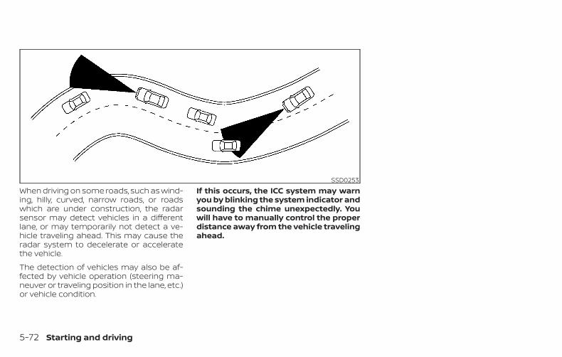
When driving on some roads, such as wind-ing, hilly, curved, narrow roads, or roadswhich are under construction, the radarsensor may detect vehicles in a differentlane, or may temporarily not detect a ve-hicle traveling ahead. This may cause theradar system to decelerate or acceleratethe vehicle.
The detection of vehicles may also be af-fected by vehicle operation (steering ma-neuver or traveling position in the lane, etc.)or vehicle condition.
If this occurs, the ICC system may warnyou by blinking the system indicator andsounding the chime unexpectedly. Youwill have to manually control the properdistance away from the vehicle travelingahead.
SSD0253
5-72 Starting and driving

SYSTEM TEMPORARILYUNAVAILABLEThe following are conditions in which theICC system may be temporarily unavail-able. In these instances, the ICC systemmay not cancel and may not be able tomaintain the selected following distancefrom the vehicle ahead.
Condition A
Under the following conditions, the ICC systemis automatically canceled. A chime will soundand the system will not be able to be set:
∙ When the VDC system is turned off
∙ When the VDC operates
∙ When a vehicle ahead is not detectedand your vehicle is traveling below thespeed of 15 mph (24 km/h)
∙ When the system judges the vehicle isat a standstill
∙ When the shift lever is not in the D (Drive)or Manual mode
∙ When the parking brake is applied
∙ When a wheel slips
∙ When the radar signal is temporarily in-terruptedLSD2832
Starting and driving 5-73

Action to take
When the conditions listed above are nolonger present, turn the system off usingthe ICC switch. Turn the ICC system back onto use the system.
Condition B
When the radar sensor area of the frontbumper is covered with dirt or is ob-structed, the ICC system will automaticallybe canceled.
The chime will sound and the “Unavailable:Front Radar Obstruction” warning mes-sage will appear in the vehicle informationdisplay.
When driving on roads with limited roadstructures (for example, long bridges, des-erts, snow fields, driving next to long walls),the system may illuminate the systemwarning light (orange) and display the “Un-available: Front Radar Obstruction” mes-sage.
Action to take
If the warning message appears, stop thevehicle in a safe place, place the shift leverin the P (Park) position, and turn the hybridsystem off. When the radar signal is tempo-rarily interrupted, clean the sensor area ofthe front bumper and restart the hybridsystem. If the “Unavailable: Front Radar Ob-struction” warning message continues tobe displayed, have the system checked. It isrecommended that you visit a NISSANdealer for this service.
Condition C
When the ICC system is not operatingproperly, a chime sounds and the ICC sys-tem warning light (orange) will come on.
LSD2685
5-74 Starting and driving

Action to take
If the warning light comes on, park the ve-hicle in a safe place. Turn the hybrid systemoff, restart the hybrid system, resume driv-ing and set the ICC system again.
If it is not possible to set the system orthe indicator stays on, it may indicatethat the system is malfunctioning. Al-though the vehicle is still drivable undernormal conditions, have the vehiclechecked. It is recommended that youvisit a NISSAN dealer for this service.
SYSTEM MAINTENANCEThe sensor for the ICC system �A is locatedon the front of the vehicle.
To keep the ICC system operating properly,be sure to observe the following:
∙ Always keep the sensor area clean.
∙ Do not strike or damage the areasaround the sensor.
∙ Do not attach a sticker (including trans-parent material) or install an accessorynear the sensor. This could cause failureor malfunction.
∙ Do not attach metallic objects near thesensor area (brush guard, etc.). Thiscould cause failure or malfunction.
∙ Do not alter, remove, or paint the frontbumper. Before customizing or restor-ing the front bumper, it is recom-mended that you visit a NISSAN dealer.
Radio frequency statementFor USA
FCC ID OAYARS4B
This device complies with Part 15 of the FCCRules. Operation is subject to the followingtwo conditions:
1. This device may not cause harmful in-terference, and
2. This device must accept any interfer-ence received, including interferencethat may cause undesired operation.
FCC Warning
Changes or modifications not expresslyapproved by the party responsible forcompliance could void the user’s authorityto operate the equipment.
LSD3105 LSD2690
Starting and driving 5-75
For Canada
Model: ARS4–B
IC: 4135A-ARS4B
FCC ID: OAYARS4B
This device complies with Part 15 of the FCCRules and with Industry Canada licence-exempt RSS standard(s). Operation is sub-ject to the following two conditions:
1. This device may not cause harmful in-terference, and
2. This device must accept any interfer-ence received, including interferencethat may cause undesired operation.
Le présent appareil est conforme aux CNRd’Industrie Canada applicables aux appar-eils radio exempts de licence. L’exploitationest autorisée aux deux conditions suiv-antes:
1. L’appareil ne doit pas produire debrouillage, et
2. L’utilisateur de l’appareil doit acceptertout brouillage radioélectrique subi,même si le brouillage est susceptibled’en compromettre le fonctionnement.
Radio Frequency Radiation Exposure Infor-mation:
This equipment complies with FCC radia-tion exposure limits set forth for an uncon-trolled environment.
This equipment should be installed andoperated with minimum distance of 30 cmbetween the radiator and your body.
The transmitter must not be co-located oroperating in conjunction with any other an-tenna or transmitter.
Cet équipement est conforme aux limitesd’exposition aux rayonnements IC établiespour un environnement non contrôlé. Cetéquipement doit être installé et utilisé avecun minimum de 30 cm de distance entre lasource de rayonnement et votre corps.
FCC Notice
Changes or modifications not expresslyapproved by the party responsible forcompliance could void the user’s authorityto operate the equipment.
CONVENTIONAL (fixed speed)CRUISE CONTROL MODEThis mode allows driving at a speed be-tween 25 to 90 mph (40 to 144 km/h) with-out keeping your foot on the acceleratorpedal.
WARNING∙ In the conventional (fixed speed)
cruise control mode, a warning chimedoes not sound to warn you if you aretoo close to the vehicle ahead, as nei-ther the presence of the vehicle aheadnor the vehicle-to-vehicle distance isdetected.
∙ Pay special attention to the distancebetween your vehicle and the vehicleahead of you or a collision could occur.
∙ Always confirm the setting in the ICCsystem display.
∙ Do not use the conventional (fixedspeed) cruise control mode whendriving under the followingconditions:
– When it is not possible to keep thevehicle at a set speed
5-76 Starting and driving

– In heavy traffic or in traffic that var-ies in speed
– On winding or hilly roads
– On slippery roads (rain, snow, ice,etc.)
– In very windy areas
∙ Doing so could cause a loss of vehiclecontrol and result in an accident.
Conventional (fixed speed) cruisecontrol switches
1. CANCEL switch:Deactivates the system without eras-ing the set speed
2. RES+ switch:Resumes set speed or increases speedincrementally
3. ICC switch:Master switch to activate the system
4. SET- switch:Sets desired cruise speed or reducesspeed incrementally
Conventional (fixed speed) cruisecontrol mode display andindicatorsThe display is located in the vehicle infor-mation display.
1. Cruise indicator:This indicator indicates the condition ofthe ICC system depending on a color.
∙ Cruise control ON indicator (gray): In-dicates that the ICC switch is on
∙ Cruise control SET indicator (green):Indicates that the cruising speed isset
LSD3271 LSD3268
Starting and driving 5-77

∙ Cruise control warning (yellow): Indi-cates that there is a malfunction inthe ICC system
2. Set vehicle speed indicator:This indicator indicates the set vehiclespeed. For Canadian models, thespeed is displayed in km/h.
Operating conventional (fixedspeed) cruise control modeTo turn on the conventional (fixed speed)cruise control mode, push and hold the ICCswitch �A for longer than about 1.5 sec-onds.
When pushing the ICC switch on, the con-ventional (fixed speed) cruise control modedisplay and indicators �B are displayed inthe vehicle information display. After youhold the ICC switch on for longer thanabout 1.5 seconds, the ICC system displayturns off. The cruise indicator appears. Youcan now set your desired cruising speed.
Pushing the ICC switch again will turn thesystem completely off. When the ignitionswitch is placed in the OFF position, thesystem is also automatically turned off.
To use the ICC system again, quickly pushand release the ICC switch (vehicle-to ve-hicle distance control mode) or push andhold it (conventional cruise control mode)again to turn it on.
CAUTIONTo avoid accidentally engaging cruisecontrol, make sure to turn the ICC switchoff when not using the ICC system.LSD3107
5-78 Starting and driving
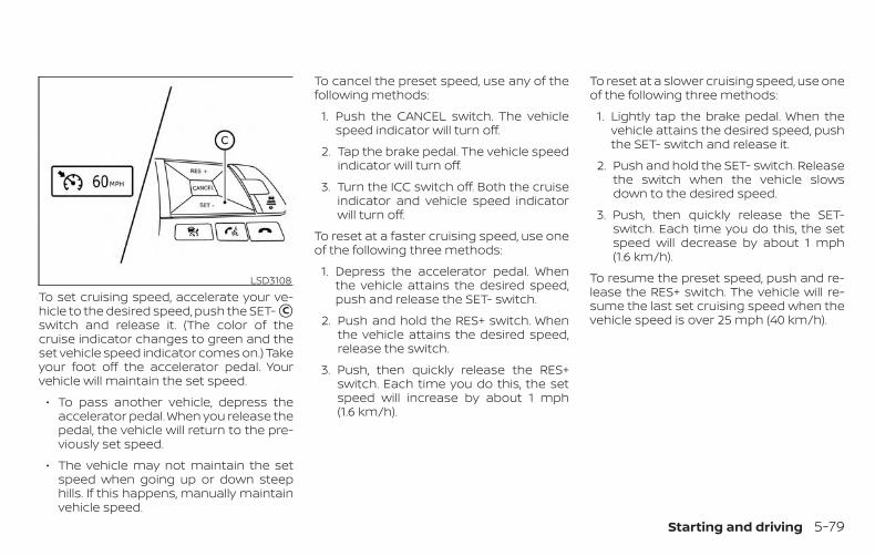
To set cruising speed, accelerate your ve-hicle to the desired speed, push the SET- �Cswitch and release it. (The color of thecruise indicator changes to green and theset vehicle speed indicator comes on.) Takeyour foot off the accelerator pedal. Yourvehicle will maintain the set speed.
∙ To pass another vehicle, depress theaccelerator pedal. When you release thepedal, the vehicle will return to the pre-viously set speed.
∙ The vehicle may not maintain the setspeed when going up or down steephills. If this happens, manually maintainvehicle speed.
To cancel the preset speed, use any of thefollowing methods:
1. Push the CANCEL switch. The vehiclespeed indicator will turn off.
2. Tap the brake pedal. The vehicle speedindicator will turn off.
3. Turn the ICC switch off. Both the cruiseindicator and vehicle speed indicatorwill turn off.
To reset at a faster cruising speed, use oneof the following three methods:
1. Depress the accelerator pedal. Whenthe vehicle attains the desired speed,push and release the SET- switch.
2. Push and hold the RES+ switch. Whenthe vehicle attains the desired speed,release the switch.
3. Push, then quickly release the RES+switch. Each time you do this, the setspeed will increase by about 1 mph(1.6 km/h).
To reset at a slower cruising speed, use oneof the following three methods:
1. Lightly tap the brake pedal. When thevehicle attains the desired speed, pushthe SET- switch and release it.
2. Push and hold the SET- switch. Releasethe switch when the vehicle slowsdown to the desired speed.
3. Push, then quickly release the SET-switch. Each time you do this, the setspeed will decrease by about 1 mph(1.6 km/h).
To resume the preset speed, push and re-lease the RES+ switch. The vehicle will re-sume the last set cruising speed when thevehicle speed is over 25 mph (40 km/h).
LSD3108
Starting and driving 5-79
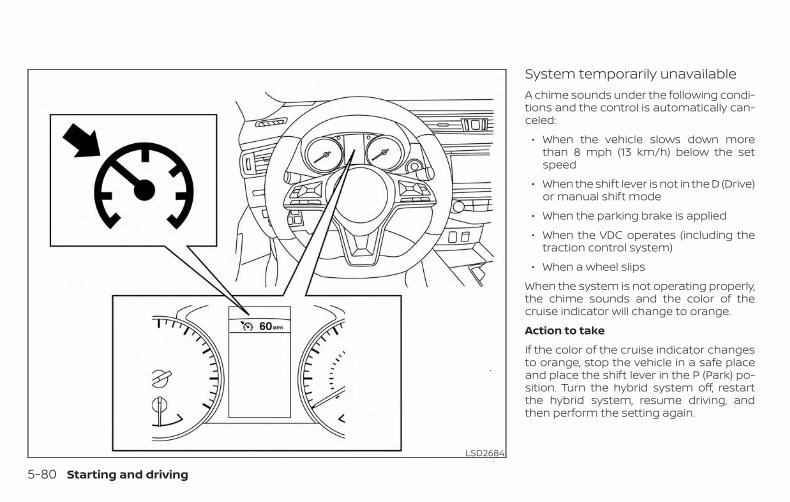
System temporarily unavailableA chime sounds under the following condi-tions and the control is automatically can-celed:
∙ When the vehicle slows down morethan 8 mph (13 km/h) below the setspeed
∙ When the shift lever is not in the D (Drive)or manual shift mode
∙ When the parking brake is applied
∙ When the VDC operates (including thetraction control system)
∙ When a wheel slips
When the system is not operating properly,the chime sounds and the color of thecruise indicator will change to orange.
Action to take
If the color of the cruise indicator changesto orange, stop the vehicle in a safe placeand place the shift lever in the P (Park) po-sition. Turn the hybrid system off, restartthe hybrid system, resume driving, andthen perform the setting again.
LSD2684
5-80 Starting and driving
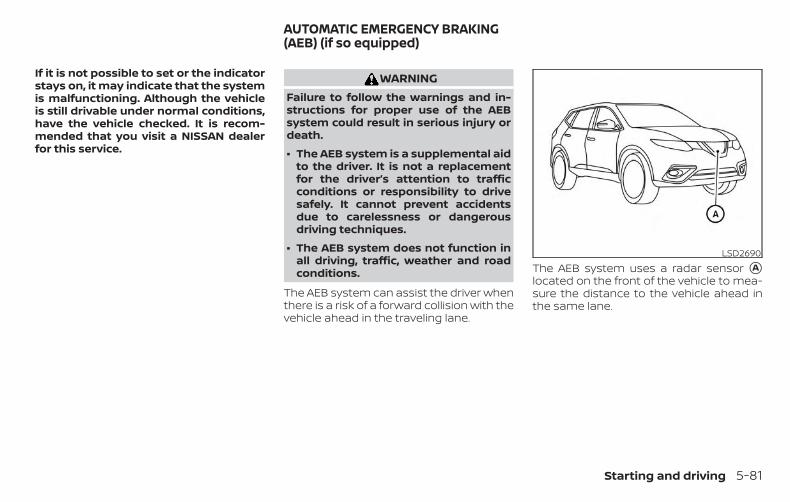
If it is not possible to set or the indicatorstays on, it may indicate that the systemis malfunctioning. Although the vehicleis still drivable under normal conditions,have the vehicle checked. It is recom-mended that you visit a NISSAN dealerfor this service.
WARNINGFailure to follow the warnings and in-structions for proper use of the AEBsystem could result in serious injury ordeath.
∙ The AEB system is a supplemental aidto the driver. It is not a replacementfor the driver’s attention to trafficconditions or responsibility to drivesafely. It cannot prevent accidentsdue to carelessness or dangerousdriving techniques.
∙ The AEB system does not function inall driving, traffic, weather and roadconditions.
The AEB system can assist the driver whenthere is a risk of a forward collision with thevehicle ahead in the traveling lane.
The AEB system uses a radar sensor �Alocated on the front of the vehicle to mea-sure the distance to the vehicle ahead inthe same lane.
LSD2690
AUTOMATIC EMERGENCY BRAKING(AEB) (if so equipped)
Starting and driving 5-81
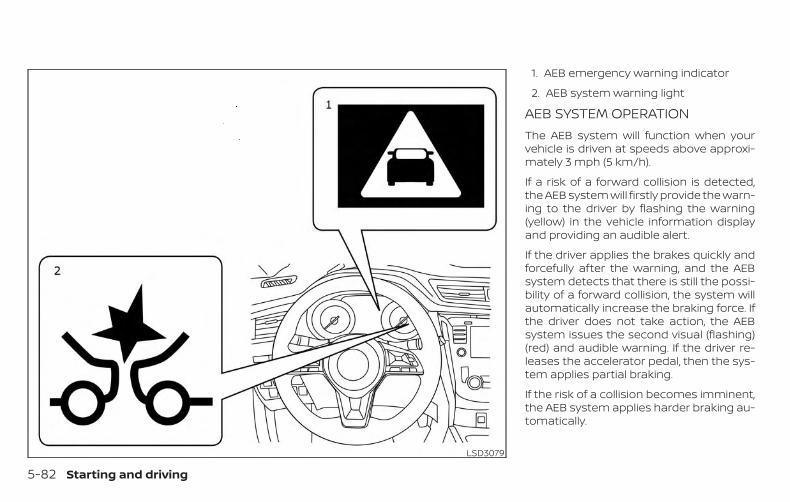
1. AEB emergency warning indicator
2. AEB system warning light
AEB SYSTEM OPERATIONThe AEB system will function when yourvehicle is driven at speeds above approxi-mately 3 mph (5 km/h).
If a risk of a forward collision is detected,the AEB system will firstly provide the warn-ing to the driver by flashing the warning(yellow) in the vehicle information displayand providing an audible alert.
If the driver applies the brakes quickly andforcefully after the warning, and the AEBsystem detects that there is still the possi-bility of a forward collision, the system willautomatically increase the braking force. Ifthe driver does not take action, the AEBsystem issues the second visual (flashing)(red) and audible warning. If the driver re-leases the accelerator pedal, then the sys-tem applies partial braking.
If the risk of a collision becomes imminent,the AEB system applies harder braking au-tomatically.
LSD3079
5-82 Starting and driving

While the AEB system is operating, you mayhear the sound of brake operation. This isnormal and indicates that the AEB systemis operating properly.
NOTE:
The vehicle’s brake lights come on whenbraking is performed by the AEB system.
Depending on vehicle speed and distanceto the vehicle ahead, as well as driving androadway conditions, the system may helpthe driver avoid a forward collision or mayhelp mitigate the consequences of a colli-sion, should one be unavoidable. If thedriver is handling the steering wheel, accel-erating or braking, the AEB system willfunction later or will not function.
The automatic braking will cease under thefollowing conditions:
∙ When the steering wheel is turned as faras necessary to avoid a collision.
∙ When the accelerator pedal is de-pressed.
∙ When there is no longer a vehicle de-tected ahead.
If the AEB system has stopped the vehicle,the vehicle will remain at a standstill forapproximately 2 seconds before thebrakes are released.
Starting and driving 5-83
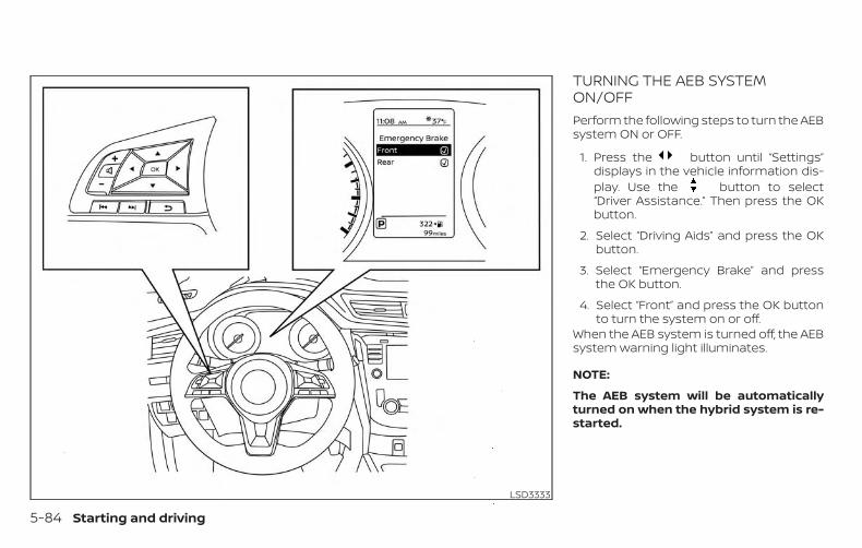
TURNING THE AEB SYSTEMON/OFFPerform the following steps to turn the AEBsystem ON or OFF.
1. Press the button until “Settings”displays in the vehicle information dis-play. Use the button to select“Driver Assistance.” Then press the OKbutton.
2. Select “Driving Aids” and press the OKbutton.
3. Select “Emergency Brake” and pressthe OK button.
4. Select “Front” and press the OK buttonto turn the system on or off.
When the AEB system is turned off, the AEBsystem warning light illuminates.
NOTE:
The AEB system will be automaticallyturned on when the hybrid system is re-started.
LSD3333
5-84 Starting and driving

AEB SYSTEM LIMITATIONS
WARNINGListed below are the system limitationsfor the AEB system. Failure to operatethe vehicle in accordance with thesesystem limitations could result in seri-ous injury or death.
∙ The AEB system cannot detect all ve-hicles under all conditions.
∙ The radar sensor does not detect thefollowing objects:
– Pedestrians, animals or obstaclesin the roadway.
– Oncoming vehicles.
– Crossing vehicles.
∙ The radar sensor has some perfor-mance limitations. If a stationary ve-hicle is in the vehicle’s path, the AEBsystem will not function when the ve-hicle is driven at speeds over approxi-mately 50 mph (80 km/h).
∙ The radar sensor may not detect a ve-hicle ahead in the followingconditions:
– Dirt, ice, snow or other materialcovering the radar sensor.
– Interference by other radarsources.
– Snow or road spray from travelingvehicles.
– If the vehicle ahead is narrow (e.g.,motorcycle).
– When driving on a steep downhillslope or roads with sharp curves.
∙ In some road or traffic conditions, theAEB system may unexpectedly applypartial braking. When acceleration isnecessary, continue to depress theaccelerator pedal to override thesystem.
∙ Braking distances increase on slip-pery surfaces.
∙ The system is designed to automati-cally check the sensor’s functionality,within certain limitations. The systemmay not detect some forms of ob-structions of the sensor area such asice, snow, stickers, etc. In these cases,the system may not be able to warnthe driver properly. Be sure that youcheck, clean and clear the sensor arearegularly.
∙ Excessive noise will interfere with thewarning chime sound, and the chimemay not be heard.
Starting and driving 5-85
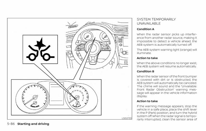
SYSTEM TEMPORARILYUNAVAILABLECondition A
When the radar sensor picks up interfer-ence from another radar source, making itimpossible to detect a vehicle ahead, theAEB system is automatically turned off.
The AEB system warning light (orange) willilluminate.
Action to take
When the above conditions no longer exist,the AEB system will resume automatically.
Condition B
When the radar sensor of the front bumperis covered with dirt or is obstructed, theAEB system will automatically be canceled.The chime will sound and the “Unvailable:Front Radar Obstruction” warning mes-sage will appear in the vehicle informationdisplay.
Action to take
If the warning message appears, stop thevehicle in a safe place, place the shift leverin the P (Park) position, and turn the hybridsystem off. When the radar signal is tempo-rarily interrupted, clean the sensor area ofLSD2733
5-86 Starting and driving

the front bumper and restart the hybridsystem. If the “Unavailable: Front Radar Ob-struction” warning message continues tobe displayed, have the system checked. It isrecommended that you visit a NISSANdealer for this service.
Condition C
When driving on roads with limited roadstructures or buildings (for example, longbridges, deserts, snow fields, driving next tolong walls), the system may illuminate thesystem warning light and display the “Un-available: Front Radar Obstruction” mes-sage.
Action to take
When the above driving conditions no lon-ger exist, turn the system back on.
SYSTEM MALFUNCTIONIf the AEB system malfunctions, it will beturned off automatically, a chime willsound, the AEB system warning light (or-ange) will illuminate and the warning mes-sage [Malfunction] will appear in the vehicleinformation display.
Action to take
If the warning light (orange) comes on, stopthe vehicle in a safe location, turn the hy-brid system off and restart the hybrid sys-tem. If the warning light continues to illumi-nate, have the AEB system checked. It isrecommended that you visit a NISSANdealer for this service.
SYSTEM MAINTENANCEThe sensor �A is located on the front of thevehicle.
To keep the system operating properly, besure to observe the following:
∙ Always keep the sensor area of the frontbumper clean.
∙ Do not strike or damage the areasaround the sensor.
∙ Do not cover or attach stickers or simi-lar objects on the front bumper nearthe sensor area. This could cause failureor malfunction.
LSD2690
Starting and driving 5-87
∙ Do not attach metallic objects near thesensor area (brush guard, etc.). Thiscould cause failure or malfunction.
∙ Do not alter, remove or paint the frontbumper. Before customizing or restor-ing the front bumper, it is recom-mended that you visit a NISSAN dealer.
Radio frequency statement
For USA
FCC ID OAYARS4B
This device complies with Part 15 of theFCC Rules. Operation is subject to the fol-lowing two conditions:
1. This device may not cause harmfulinterference, and
2. This device must accept any interfer-ence received, including interferencethat may cause undesired operation.
FCC Warning
Changes or modifications not expresslyapproved by the party responsible forcompliance could void the user’s author-ity to operate the equipment.
For Canada
Model: ARS4–B
IC: 4135A-ARS4B
FCC ID: OAYARS4B
This device complies with Part 15 of the FCCRules and with Industry Canada licence-exempt RSS standard(s). Operation is sub-ject to the following two conditions:
1. This device may not cause interfer-ence, and
2. This device must accept any interfer-ence received, including interferencethat may cause undesired operationof the device.
Le présent appareil est conforme auxCNR d’Industrie Canada applicables auxappareils radio exempts de licence.L’exploitation est autorisée aux deuxconditions suivantes:
1. L’appareil ne doit pas produire debrouillage, et
2. L’utilisateur de l’appareil doit ac-cepter tout brouillage radioélec-trique subi, même si le brouillage estsusceptible d’en compromettre lefonctionnement.
Radio frequency radiation exposure in-formation:
This equipment complies with FCC and ICradiation exposure limits set forth for anuncontrolled environment.
This equipment should be installed andoperated with minimum distance of30 cm between the radiator and yourbody.
This transmitter must not be co-locatedor operating in conjunction with anyother antenna or transmitter.
Cet équipement est conforme aux lim-ites d’exposition aux rayonnements ICétablies pour un environnement noncontrôlé.
Cet équipement doit être installé etutilisé avec un minimum de 30 cm dedistance entre la source de rayonnementet votre corps.
FCC Notice
Changes or modifications not expresslyapproved by the party responsible forcompliance could void the user’s author-ity to operate the equipment.
5-88 Starting and driving

WARNINGFailure to follow the warnings and in-structions for proper use of the AEBwith Pedestrian Detection systemcould result in serious injury or death.
∙ The AEB with Pedestrian Detectionsystem is a supplemental aid to thedriver. It is not a replacement for thedriver’s attention to traffic conditionsor responsibility to drive safely. It can-not prevent accidents due to care-lessness or dangerous drivingtechniques.
∙ The AEB with Pedestrian Detectionsystem does not function in all driv-ing, traffic, weather and roadconditions.
The AEB with Pedestrian Detection systemcan assist the driver when there is a risk ofa forward collision with the vehicle ahead inthe traveling lane or with a pedestrianahead in the traveling lane.
The AEB with Pedestrian Detection systemuses a radar sensor located on the front ofthe vehicle �B to measure the distance tothe vehicle ahead in the same lane. Forpedestrians, the AEB with Pedestrian De-tection system uses a camera installed be-hind the windshield �A in addition to theradar sensor.
LSD2799
AUTOMATIC EMERGENCY BRAKING(AEB) WITH PEDESTRIAN DETECTION(if so equipped)
Starting and driving 5-89

1. AEB with Pedestrian Detection emer-gency warning indicator
2. AEB with Pedestrian Detection systemwarning light
AEB WITH PEDESTRIANDETECTION SYSTEM OPERATIONThe AEB system operates at speeds aboveapproximately 3 mph (5 km/h). For the pe-destrian detection function, the systemoperates at speeds between 6 – 37 mph (10– 60 km/h).
If a risk of a forward collision is detected,the AEB with Pedestrian Detection systemwill firstly provide the warning to the driverby flashing the warning (yellow) in the ve-hicle information display and providing anaudible alert. If the driver applies the brakesquickly and forcefully after the warning,and the AEB with Pedestrian Detection sys-tem detects that there is still the possibilityof a forward collision, the system will auto-matically increase the braking force.
If the driver does not take action, the AEBwith Pedestrian Detection system issuesthe second visual (flashing) (red) and au-dible warning. If the driver releases the ac-celerator pedal, then the system appliespartial braking. If the risk of a collision be-LSD3079
5-90 Starting and driving
comes imminent, the AEB with PedestrianDetection system applies harder brakingautomatically.
While the AEB with Pedestrian Detectionsystem is operating, you may hear thesound of brake operation. This is normaland indicates that the AEB with PedestrianDetection system is operating properly.
NOTE:
The vehicle’s brake lights come on whenany braking is performed by the AEBwith Pedestrian Detection system.
Depending on vehicle speed and distanceto the vehicle or pedestrian ahead, as wellas driving and roadway conditions, the sys-tem may help the driver avoid a forwardcollision or may help mitigate the conse-quences if a collision should be unavoid-able. If the driver is handling the steeringwheel, accelerating or braking, the AEB withPedestrian Detection system will functionlater or will not function.
The automatic braking will cease under thefollowing conditions:
∙ When the steering wheel is turned toavoid a collision.
∙ When the accelerator pedal is de-pressed.
∙ When there is no longer a vehicle or apedestrian detected ahead.
If the AEB with Pedestrian Detection sys-tem has stopped the vehicle, the vehiclewill remain at a standstill for approximately2 seconds before the brakes are released.
Starting and driving 5-91

TURNING THE AEB WITHPEDESTRIAN DETECTION SYSTEMON/OFFPerform the following steps to enable ordisable the AEB with Pedestrian Detectionsystem.
1. Press the button until “Settings”displays in the vehicle information dis-play. Use the button to select“Driver Assistance.” Then press the OKbutton.
2. Select “Driving Aids” and press the OKbutton.
3. Select “Emergency Brake” and pressthe OK button.
4. Select “Front” and press the OK buttonto turn the system on or off.
When the AEB with Pedestrian Detectionsystem is turned off, the AEB with Pedes-trian Detection system warning light illumi-nates.
NOTE:
The AEB with Pedestrian Detection sys-tem will be automatically turned onwhen the hybrid system is restarted.
LSD3333
5-92 Starting and driving

AEB WITH PEDESTRIANDETECTION SYSTEM LIMITATIONS
WARNINGListed below are the system limitationsfor the AEB with Pedestrian Detectionsystem. Failure to operate the vehicle inaccordance with these system limita-tions could result in serious injury ordeath.
∙ The AEB with Pedestrian Detectionsystem cannot detect all vehicles orpedestrians under all conditions.
∙ The AEB with Pedestrian Detectionsystem does not detect the followingobjects:
– Small pedestrians (including smallchildren), animals and cyclists.
– Pedestrians in wheelchairs or us-ing mobile transport such asscooters, child-operated toys, orskateboards.
– Pedestrians who are seated or oth-erwise not in a full upright stand-ing or walking position.
– Oncoming vehicles
– Crossing vehicles
– Obstacles on the roadside
∙ The AEB with Pedestrian Detectionsystem has some performancelimitations.
– If a stationary vehicle is in the vehi-cle’s path, the AEB with PedestrianDetection system will not functionwhen the vehicle is driven atspeeds over approximately50 mph (80 km/h).
– For pedestrian detection, the AEBwith Pedestrian Detection systemwill not function when the vehicleis driven at speeds over approxi-mately 37 mph (60 km/h) or belowapproximately 6 mph (10 km/h).
∙ The AEB with Pedestrian Detectionsystem will not function for pedestri-ans in darkness or in tunnels, even ifthere is street lighting in the area.
∙ The AEB with Pedestrian Detectionsystem may not function if the vehicleahead is narrow (for example, amotorcycle).
∙ The AEB with Pedestrian Detectionsystem may not function if the speeddifference between the two vehicles istoo small.
∙ The radar sensor AEB with PedestrianDetection system may not functionproperly or detect a vehicle ahead inthe following conditions:
– Poor visibility (conditions such asrain, snow, fog, dust storms, sand-storms, and road spray from othervehicles)
– Driving on a steep downhill slopeor roads with sharp curves.
– Driving on a bumpy road surface,such as an uneven dirt road.
– If dirt, ice, snow or other material iscovering the radar sensor area.
– Interference by other radarsources.
– The camera area of the windshieldis fogged up, or covered with dirt,water drops, ice, snow, etc.
Starting and driving 5-93
– Strong light (for example, sunlightor high beams from oncoming ve-hicles) enters the front camera.Strong light causes the areaaround the pedestrian to be cast ina shadow, making it difficult to see.
– A sudden change in brightness oc-curs. (For example, when the ve-hicle enters or exits a tunnel or ashaded area or lightning flashes.)
– The poor contrast of a person tothe background, such as havingclothing color or pattern which issimilar to the background.
– The pedestrian’s profile is partiallyobscured or unidentifiable due tothe pedestrian transporting lug-gage, wearing bulky or very loose-fitting clothing or accessories.
∙ The system performance may de-grade in the following conditions:
– The vehicle is driven on a slipperyroad.
– The vehicle is driven on a slope.
– Excessively heavy baggage isloaded in the rear seat or the trunkroom of your vehicle.
∙ The system is designed to automati-cally check the sensor’s (radar andcamera) functionality, within certainlimitations. The system may not de-tect blockage of sensor areas coveredby ice, snow or stickers, for example.In these cases, the system may not beable to warn the driver properly. Besure that you check, clean and clearsensor areas regularly.
∙ In some road and traffic conditions,the AEB with Pedestrian Detectionsystem may unexpectedly apply par-tial braking. When acceleration is nec-essary, depress the accelerator pedalto override the system.
∙ Excessive noise will interfere with thewarning chime sound, and the chimemay not be heard.
5-94 Starting and driving
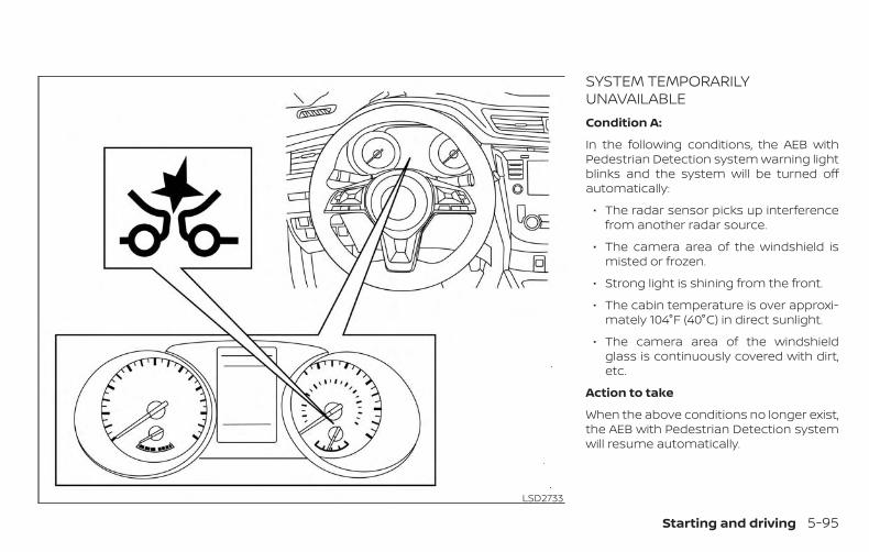
SYSTEM TEMPORARILYUNAVAILABLECondition A:
In the following conditions, the AEB withPedestrian Detection system warning lightblinks and the system will be turned offautomatically:
∙ The radar sensor picks up interferencefrom another radar source.
∙ The camera area of the windshield ismisted or frozen.
∙ Strong light is shining from the front.
∙ The cabin temperature is over approxi-mately 104°F (40°C) in direct sunlight.
∙ The camera area of the windshieldglass is continuously covered with dirt,etc.
Action to take
When the above conditions no longer exist,the AEB with Pedestrian Detection systemwill resume automatically.
LSD2733
Starting and driving 5-95

NOTE:
When the inside of the windshield on thecamera area is misted or frozen, it willtake a period of time to remove it afterthe A/C turns on. If dirt appears on thisarea, it is recommended that you visit aNISSAN dealer.
Condition B
When the radar sensor of the front bumperis covered with dirt or is obstructed, theAEB with Pedestrian Detection system willautomatically be canceled. The chime willsound and the “Unavailable: Front RadarObstruction” warning message will appearin the vehicle information display.
Action to take
If the warning message appears, stop thevehicle in a safe place, place the shift leverin the P (Park) position, and turn the hybridsystem off. When the radar signal is tempo-rarily interrupted, clean the sensor area ofthe front bumper and restart the hybridsystem. If the “Unavailable: Front Radar Ob-struction” warning message continues tobe displayed, have the system checked. It isrecommended that you visit a NISSANdealer for this service.
Condition C
When driving on roads with limited roadstructures or buildings (for example, longbridges, deserts, snow fields, driving next tolong walls), the system may illuminate thesystem warning light and display the “Un-available: Front Radar Obstruction” message.
Action to take
When the above driving conditions no lon-ger exist, turn the system back on.
SYSTEM MALFUNCTIONIf the AEB with Pedestrian Detection sys-tem malfunctions, it will be turned off auto-matically, a chime will sound, the AEB withPedestrian Detection system warning light(orange) will illuminate and the warningmessage [Malfunction] will appear in thevehicle information display.
Action to take
If the warning light (orange) comes on, stopthe vehicle in a safe location, turn the hy-brid system off and restart the hybrid sys-tem. If the warning light continues to illumi-nate, have the AEB with PedestrianDetection system checked. It is recom-mended that you visit a NISSAN dealer forthis service.
SYSTEM MAINTENANCEThe radar sensor is located on the front ofthe vehicle �B . The camera is located onthe upper side of the windshield �A .
To keep the AEB with Pedestrian Detectionsystem operating properly, be sure to ob-serve the following:
∙ Always keep the sensor areas of thefront bumper and windshield clean.
∙ Do not strike or damage the areasaround the sensors (e.g., bumper, wind-shield).
LSD2799
5-96 Starting and driving

∙ Do not cover or attach stickers, or installany accessory near the sensors. Thiscould block sensor signals and/orcause failure or malfunction.
∙ Do not attach metallic objects near theradar sensor (brush guard, etc.). Thiscould cause failure or malfunction.
∙ Do not place reflective materials, suchas white paper or a mirror, on the instru-ment panel. The reflection of sunlightmay adversely affect the camera unit’sdetection capability.
∙ Do not alter, remove or paint the frontbumper. Before customizing or restor-ing the front bumper, it is recom-mended that you visit a NISSAN dealer.
Radio frequency statementFor USA
FCC ID OAYARS4B
This device complies with Part 15 of theFCC Rules. Operation is subject to the fol-lowing two conditions:
1. This device may not cause harmfulinterference, and
2. This device must accept any interfer-ence received, including interferencethat may cause undesired operation.
FCC Warning
Changes or modifications not expresslyapproved by the party responsible forcompliance could void the user’s author-ity to operate the equipment.
For Canada
Model: ARS4–B
IC: 4135A-ARS4B
FCC ID: OAYARS4B
This device complies with Part 15 of theFCC Rules and with Industry Canadalicence-exempt RSS standard(s). Opera-tion is subject to the following two con-ditions:
1. This device may not cause interfer-ence, and
2. This device must accept any interfer-ence received, including interferencethat may cause undesired operationof the device.
Le présent appareil est conforme auxCNR d’Industrie Canada applicables auxappareils radio exempts de licence.L’exploitation est autorisée aux deuxconditions suivantes:
1. L’appareil ne doit pas produire debrouillage, et
2. L’utilisateur de l’appareil doit ac-cepter tout brouillage radioélec-trique subi, même si le brouillage estsusceptible d’en compromettre lefonctionnement.
Radio frequency radiation exposure in-formation:
This equipment complies with FCC and ICradiation exposure limits set forth for anuncontrolled environment.
This equipment should be installed andoperated with minimum distance of30 cm between the radiator and yourbody.
This transmitter must not be co-locatedor operating in conjunction with anyother antenna or transmitter.
Starting and driving 5-97

Cet équipement est conforme aux lim-ites d’exposition aux rayonnements ICétablies pour un environnement noncontrôlé.
Cet équipement doit être installé etutilisé avec un minimum de 30 cm dedistance entre la source de rayonnementet votre corps.
FCC Notice
Changes or modifications not expresslyapproved by the party responsible forcompliance could void the user’s author-ity to operate the equipment.
WARNINGFailure to follow the warnings and in-structions for proper use of the RABsystem could result in serious injury ordeath.
∙ The RAB system is a supplemental aidto the driver. It is not a replacementfor proper driving procedures. Alwaysuse the side and rear mirrors and turnand look in the direction you will movebefore and while backing up. Neverrely solely on the RAB system. It is thedriver’s responsibility to stay alert,drive safely, and be in control of thevehicle at all times.
∙ There is a limitation to the RAB systemcapability. The RAB system is not ef-fective in all situations.
The RAB system can assist the driver whenthe vehicle is backing up and approachingobjects directly behind the vehicle.
The RAB system detects obstacles behindthe vehicle using the parking sensors �1located on the rear bumper.
NOTE:
You can temporarily cancel the sonarfunction in the vehicle, but the RAB sys-tem will continue to operate. For addi-tional information, please refer to “RearSonar System (RSS)” in this section.
LSD3334
REAR AUTOMATIC BRAKING (RAB) (ifso equipped)
5-98 Starting and driving
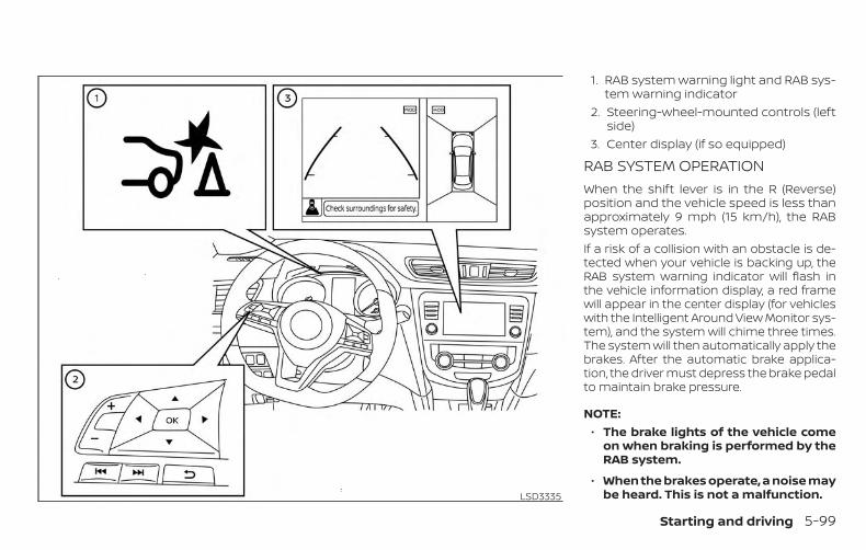
1. RAB system warning light and RAB sys-tem warning indicator
2. Steering-wheel-mounted controls (leftside)
3. Center display (if so equipped)
RAB SYSTEM OPERATIONWhen the shift lever is in the R (Reverse)position and the vehicle speed is less thanapproximately 9 mph (15 km/h), the RABsystem operates.If a risk of a collision with an obstacle is de-tected when your vehicle is backing up, theRAB system warning indicator will flash inthe vehicle information display, a red framewill appear in the center display (for vehicleswith the Intelligent Around View Monitor sys-tem), and the system will chime three times.The system will then automatically apply thebrakes. After the automatic brake applica-tion, the driver must depress the brake pedalto maintain brake pressure.
NOTE:∙ The brake lights of the vehicle come
on when braking is performed by theRAB system.
∙ When the brakes operate, a noise maybe heard. This is not a malfunction.LSD3335
Starting and driving 5-99

TURNING THE RAB SYSTEMON/OFFPerform the following steps to turn the RABsystem ON or OFF.
1. Press the button until “Settings”displays in the vehicle information dis-play. Use the button to select“Driver Assistance.” Then press the OKbutton.
2. Select “Driving Aids” and press the OKbutton.
3. Select “Emergency Brake” and pressthe OK button.
4. To set the RAB system to on or off, usethe OK button to check the box for“Rear.”
When the RAB system is turned off, the RABsystem warning light illuminates.
NOTE:
The RAB system will be automaticallyturned on when the hybrid system is re-started.
LSD3333
5-100 Starting and driving

RAB SYSTEM LIMITATIONS
WARNINGListed below are the system limitationsfor the RAB system. Failure to follow thewarnings and instructions for properuse of the RAB system could result inserious injury or death.
∙ When the vehicle approaches an ob-stacle while the accelerator or brakepedal is depressed, the function maynot operate or the start of the opera-tion may be delayed. The RAB systemmay not operate or may not performsufficiently due to vehicle conditions,driving conditions, the traffic environ-ment, the weather, road surface con-ditions, etc. Do not wait for the systemto operate. Operate the brake pedalby yourself as soon as necessary.
∙ If it is necessary to override RAB op-eration, strongly press the acceleratorpedal.
∙ Always check your surroundings andturn to check what is behind you be-fore and while backing up. The RABsystem detects stationary objects be-hind the vehicle. The RAB system doesnot detect the following objects:
– Moving objects
– Low objects
– Narrow objects
– Wedge-shaped objects
– Objects close to the bumper (lessthan approximately 1 ft [30 cm])
– Objects that suddenly appear
– Thin objects such as rope, wire,chain, etc.
∙ The RAB system may not operate forthe following obstacles:
– Obstacles located high off theground
– Obstacles in a position offset fromyour vehicle
– Obstacles, such as spongy materi-als or snow, that have soft outersurfaces and can easily absorb asound wave
∙ The RAB system may not operate inthe following conditions:
– There is rain, snow, ice, dirt, etc., at-tached to the sonar sensors.
– A loud sound is heard in the areaaround the vehicle.
– The surface of the obstacle is di-agonal to the rear of the vehicle.
∙ The RAB system may unintentionallyoperate in the following conditions:
– There is overgrown grass in thearea around the vehicle.
– There is a structure (e.g., a wall, tollgate equipment, a narrow tunnel, aparking lot gate) near the side ofthe vehicle.
– There are bumps, protrusions, ormanhole covers on the roadsurface.
– The vehicle drives through adraped flag or a curtain.
– There is an accumulation of snowor ice behind the vehicle.
– An ultrasonic wave source, such asanother vehicle’s sonar, is near thevehicle.
Starting and driving 5-101

∙ Once the automatic brake control op-erates, it does not operate again if thevehicle approaches the sameobstacle.
∙ The automatic brake control can onlyoperate for a short period of time.Therefore, the driver must depressthe brake pedal.
∙ In the following situations, the RABsystem may not operate properly ormay not function sufficiently:
– The vehicle is driven in badweather (rain, fog, snow, etc.).
– The vehicle is driven on a steep hill.
– The vehicle’s posture is changed(e.g., when driving over a bump).
– The vehicle is driven on a slipperyroad.
– The vehicle is turned sharply byturning the steering wheel fully.
– Snow chains are used.
– Wheels or tires other than NISSANrecommended are used.
– The brakes are cold at low ambienttemperatures or immediately afterdriving has started.
– The braking force becomes poordue to wet brakes after drivingthrough a puddle or washing thevehicle.
∙ Turn the RAB system off in the follow-ing conditions to prevent the occur-rence of an unexpected accident re-sulting from sudden systemoperation:
– The vehicle is towed.
– The vehicle is carried on a flatbedtruck.
– The vehicle is on the chassisdynamometer.
– The vehicle drives on an unevenroad surface.
– Suspension parts other than thosedesignated as genuine parts areused. (If the vehicle height or thevehicle body inclination ischanged, the system may not de-tect an obstacle correctly.)
∙ Excessive noise (e.g., audio systemvolume, an open vehicle window) willinterfere with the chime sound, and itmay not be heard.
SYSTEM MALFUNCTIONIf the RAB system malfunctions, it will beturned off automatically, the RAB systemwarning light will illuminate, and the “Sys-tem fault” warning message will appear inthe vehicle information display.
Action to take
If the warning light illuminates, park the ve-hicle in a safe location, turn the hybrid sys-tem off, and restart the hybrid system. If thewarning light continues to illuminate, havethe RAB system checked. It is recom-mended that you visit a NISSAN dealer forthis service.
NOTE:
If the RAB system cannot be operatedtemporarily, the RAB system warninglight blinks.
5-102 Starting and driving

SYSTEM MAINTENANCEObserve the following items to ensureproper operation of the system:
∙ Always keep the parking sensors �1clean.
∙ If the parking sensors are dirty, wipethem off with a soft cloth while beingcareful to not damage them.
∙ Do not subject the area around theparking sensors �1 to strong impact.Also, do not remove or disassemble theparking sensors. If the parking sensorsand peripheral areas are deformed inan accident, etc., have the sensorschecked. It is recommended that youvisit a NISSAN dealer for this service.
∙ Do not install any stickers (includingtransparent stickers) or accessories onthe parking sensors �1 and their sur-rounding areas. This may cause a mal-function or improper operation.
CAUTIONDuring the first 1,200 miles (2,000 km),follow these recommendations to ob-tain maximum engine performanceand ensure the future reliability andeconomy of your new vehicle. Failure tofollow these recommendations may re-sult in shortened engine life and re-duced engine performance.
∙ Avoid driving for long periods at con-stant speed, either fast or slow, and donot run the engine over 4,000 rpm.
∙ Do not accelerate at full throttle in anygear.
∙ Avoid quick starts.
∙ Avoid hard braking as much as pos-sible.
LSD3334
BREAK-IN SCHEDULE
Starting and driving 5-103

Follow these easy-to-use Fuel EfficientDriving Tips to help you achieve the mostfuel economy from your vehicle.
1. Use Smooth Accelerator and BrakePedal Application
∙ Avoid rapid starts and stops.
∙ Use smooth, gentle accelerator andbrake application whenever possible.
∙ Maintain constant speed while com-muting and coast whenever pos-sible.
2. Maintain Constant Speed
∙ Look ahead to try and anticipate andminimize stops.
∙ Synchronizing your speed with trafficlights allows you to reduce your num-ber of stops.
∙ Maintaining a steady speed can mini-mize red light stops and improve fuelefficiency.
3. Use Air Conditioning (A/C) at HigherVehicle Speeds
∙ Below 40 mph (64 km/h), it is moreefficient to open windows to cool thevehicle due to reduced engine load.
∙ Above 40 mph (64 km/h), it is moreefficient to use A/C to cool the vehicledue to increased aerodynamic drag.
∙ Recirculating the cool air in the cabinwhen the A/C is on reduces coolingload.
4. Drive at Economical Speeds and Dis-tances
∙ Observing the speed limit and notexceeding 60 mph (97 km/h) (wherelegally allowed) can improve fuel effi-ciency due to reduced aerodynamicdrag.
∙ Maintaining a safe following distancebehind other vehicles reduces un-necessary braking.
∙ Safely monitoring traffic to anticipatechanges in speed permits reducedbraking and smooth accelerationchanges.
∙ Select a gear range suitable to roadconditions.
5. Use Cruise Control
∙ Using cruise control during highwaydriving helps maintain a steadyspeed.
∙ Cruise control is particularly effectivein providing fuel savings when drivingon flat terrains.
6. Plan for the Shortest Route
∙ Utilize a map or navigation system todetermine the best route to savetime.
7. Avoid Idling
∙ Shutting off your hybrid system whensafe for stops exceeding 30–60 sec-onds saves fuel and reduces emis-sions.
8. Buy an Automated Pass for TollRoads
∙ Automated passes permit drivers touse special lanes to maintain cruis-ing speed through the toll and avoidstopping and starting.
9. Winter Warm Up
∙ Limit idling time to minimize impactto fuel economy.
∙ Vehicles typically need no more than30 seconds of idling at start-up toeffectively circulate the engine oil be-fore driving.
FUEL EFFICIENT DRIVING TIPS
5-104 Starting and driving
∙ Your vehicle will reach its ideal oper-ating temperature more quicklywhile driving versus idling.
10. Keeping your Vehicle Cool
∙ Park your vehicle in a covered parkingarea or in the shade whenever pos-sible.
∙ When entering a hot vehicle, openingthe windows will help to reduce theinside temperature faster, resulting inreduced demand on your A/C sys-tem.
∙ Keep your engine tuned up.
∙ Follow the recommended scheduledmaintenance.
∙ Keep the tires inflated to the correctpressure. Low tire pressure increasestire wear and lowers fuel economy.
∙ Keep all the wheels in correct align-ment. Improper alignment increasestire wear and lowers fuel economy.
∙ Use the recommended viscosity engineoil. For additional information, refer to“Engine oil and oil filter recommenda-tions” in the “Technical and consumerinformation” section of this manual.
If any malfunction occurs in the AWD sys-tem while the engine is running, the masterwarning light will come on.
The master warning light may illuminatewhile trying to free a stuck vehicle due tohigh powertrain oil temperature. The driv-ing mode may change to 2–Wheel Drive.AUTO mode may change to LOCK modebefore the warning light illuminates. If themaster warning light illuminates duringoperation, stop the vehicle with the engineidling in a safe place immediately. Then, ifthe light turns off after a while, you cancontinue driving.
A large difference between the diametersof the front and rear wheels will make thewarning light illuminate. Pull off the road ina safe area and idle the engine. Check thatall tire sizes are the same, tire pressure iscorrect, and the tires are not worn.
INCREASING FUEL ECONOMY ALL-WHEEL DRIVE (AWD) (if soequipped)
Starting and driving 5-105
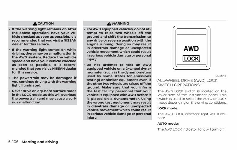
CAUTION∙ If the warning light remains on after
the above operation, have your ve-hicle checked as soon as possible. It isrecommended that you visit a NISSANdealer for this service.
∙ If the warning light comes on whiledriving, there may be a malfunction inthe AWD system. Reduce the vehiclespeed and have your vehicle checkedas soon as possible. It is recom-mended that you visit a NISSAN dealerfor this service.
∙ The powertrain may be damaged ifyou continue driving with the warninglight illuminated.
∙ Never drive on dry, hard surface roadsin the LOCK mode, as this will overloadthe powertrain and may cause a seri-ous malfunction.
WARNING∙ For AWD equipped vehicles, do not at-
tempt to raise two wheels off theground and shift the transmission toany drive or reverse position with theengine running. Doing so may resultin drivetrain damage or unexpectedvehicle movement which could resultin serious vehicle damage or personalinjury.
∙ Do not attempt to test an AWDequipped vehicle on a 2–wheel dyna-mometer (such as the dynamometersused by some states for emissionstesting) or similar equipment even ifthe other two wheels are raised off theground. Make sure that you informthe test facility personnel that yourvehicle is equipped with AWD before itis placed on a dynamometer. Usingthe wrong test equipment may resultin drivetrain damage or unexpectedvehicle movement which could resultin serious vehicle damage or personalinjury.
ALL-WHEEL DRIVE (AWD) LOCKSWITCH OPERATIONSThe AWD LOCK switch is located on thelower side of the instrument panel. Thisswitch is used to select the AUTO or LOCKmode depending on the driving conditions.
LOCK mode:
The AWD LOCK indicator light will illumi-nate.
AUTO mode:
The AWD LOCK indicator light will turn off.
LIC2645
5-106 Starting and driving

AWD mode Wheels driven AWD LOCK indicator light Use conditions
AUTO
Distribution of torqueto the front and rearwheels changesautomatically, depend-ing on road conditionsencountered [100:0]←→ [50:50]. This resultsin improved drivingstability. *1
For driving on pavedor slippery roads.
LOCK AWD *2, *3 For driving on roughroads.
*1 When the rotation difference between the front and rear wheels is large, the AWD modemay change from AUTO to LOCK for a while; however, this is not a malfunction.
*2 The LOCK mode will change to AUTO mode automatically when the vehicle has beendriven at a high speed. The AWD LOCK indicator light turns off.
*3 LOCK mode will automatically be canceled when the ignition switch is placed in the OFFposition.
∙ The AWD torque distribution betweenthe front and rear wheels can be dis-played in the video information display.
∙ If the AWD LOCK switch is operatedwhile accelerating or decelerating, or ifthe ignition switch is placed in the OFFposition, you may feel a jolt. This is nor-mal.
∙ The oil temperature of the powertrainparts will increase if the vehicle is con-tinuously operated under conditionswhere the difference in rotation be-tween the front and rear wheels is large(wheel slip), such as when driving thevehicle on rough roads or through sandor mud or freeing a stuck vehicle. Inthese cases, the master warning lightilluminates and the AWD modechanges to 2–Wheel Drive to protect thepowertrain parts. Stop driving with theengine idling and wait until the warninglight turns off and the AWD returns tothe AUTO mode. If the warning light re-mains on, have your vehicle checked assoon as possible. It is recommendedthat you visit a NISSAN dealer for thisservice.
Starting and driving 5-107

WARNING∙ When driving straight, shift the AWD
LOCK switch to AUTO. Do not operatethe AWD LOCK switch when making aturn or backing up.
∙ Do not operate the AWD LOCK switchwith the front wheel spinning.
∙ Engine idling speed is high whilewarming up the engine. Be especiallycareful when starting or driving onslippery surfaces.
∙ When turning the vehicle in LOCKmode on paved roads, you may feel abraking effect. This is a normal condi-tion of the AWD model. WARNING
∙ Do not stop or park the vehicle overflammable materials such as drygrass, waste paper or rags. They mayignite and cause a fire.
∙ Safe parking procedures require thatboth the parking brake be set and thetransmission placed into P (Park). Fail-ure to do so could cause the vehicle tomove unexpectedly or roll away and re-sult in an accident. Make sure the shiftlever has been pushed as far forward asit can go and cannot be moved withoutdepressing the foot brake pedal.
∙ Never leave the engine running whilethe vehicle is unattended.
∙ To help avoid risk of injury or deaththrough unintended operation of thevehicle and/or its systems, do notleave children, people who require theassistance of others or pets unat-tended in your vehicle. Additionally,the temperature inside a closed ve-hicle on a warm day can quickly be-come high enough to cause a signifi-cant risk of injury or death to peopleand pets.
WSD0050
PARKING/PARKING ON HILLS
5-108 Starting and driving
1. Firmly apply the parking brake.
2. Move the shift lever to the P (Park) po-sition.
3. To help prevent the vehicle from rollinginto traffic when parked on an incline, itis a good practice to turn the wheels asillustrated.
∙ HEADED DOWNHILL WITH CURB �A :
Turn the wheels into the curb andmove the vehicle forward until the curbside wheel gently touches the curb.
∙ HEADED UPHILL WITH CURB �B :
Turn the wheels away from the curband move the vehicle back until thecurb side wheel gently touches thecurb.
∙ HEADED UPHILL OR DOWNHILL, NOCURB �C :
Turn the wheels toward the side of theroad so the vehicle will move awayfrom the center of the road if it moves.
4. Place the ignition switch in the LOCKposition.
WARNING∙ If the hybrid system is not running or
is turned off while driving, the powerassist for the steering will not work.Steering will be harder to operate
∙ When the power steering warninglight illuminates with the hybrid sys-tem running, there will be no powerassist for the steering. You will stillhave control of the vehicle but thesteering will be harder to operate.Have the power steering systemchecked. It is recommended that youvisit a NISSAN dealer for this service.
The power steering system is designed toprovide power assist while driving to oper-ate the steering wheel with light force.
When the steering wheel is operated re-peatedly or continuously while parking ordriving at a very low speed, the power as-sist for the steering wheel will be reduced.This is to prevent overheating of the powersteering system and protect it from gettingdamaged. While the power assist is re-duced, steering wheel operation will be-come heavy. If the steering wheel opera-tion is still performed, the power steeringmay stop and the power steering warninglight will illuminate. In a safe location, stop
the hybrid system and push the ignitionswitch to the OFF position. The tempera-ture of the power steering system will godown after a period of time and the powerassist level will return to normal after start-ing the hybrid system. The power steeringwarning light will go off. Avoid repeatingsuch steering wheel operations that couldcause the power steering system to over-heat.
You may hear a noise from the front of thevehicle when the steering wheel is oper-ated. This is a normal operational noiseand is not a malfunction.
If the power steering warning light PS illu-minates while the hybrid system is running,it may indicate the power steering systemis not functioning properly and may needservicing. Have the power steering systemchecked. It is recommended that you visit aNISSAN dealer for this service.
When the power steering warning light illu-minates with the hybrid system running,there will be no power assist for the steer-ing but you will still have control of the ve-hicle. At this time, greater steering effort isrequired to operate the steering wheel, es-pecially in sharp turns and at low speeds.
POWER STEERING
Starting and driving 5-109
For additional information, refer to “Powersteering warning light” in the “Instrumentsand controls” section of this manual.
The brake system has two separate hy-draulic circuits. If one circuit malfunctions,you will still have braking at two wheels.
BRAKE PRECAUTIONSVacuum assisted brakesThe brake booster aids braking by usingengine vacuum. If the engine stops, youcan stop the vehicle by depressing thebrake pedal. However, greater foot pres-sure on the brake pedal will be required tostop the vehicle and stopping distance willbe longer.
Using the brakesAvoid resting your foot on the brake pedalwhile driving. This will overheat the brakes,wear out the brake pads faster, and reducegas mileage.
To help reduce brake wear and to preventthe brakes from overheating, reduce speedand downshift to a lower gear before goingdown a slope or long grade. Overheatedbrakes may reduce braking performanceand could result in loss of vehicle control.
WARNING∙ While driving on a slippery surface, be
careful when braking, accelerating ordownshifting. Abrupt braking or ac-celerating could cause the wheels toskid and result in an accident.
∙ If the engine is not running or isturned off while driving, the power as-sist for the brakes will not work. Brak-ing will be harder.
Wet brakesWhen the vehicle is washed or driventhrough water, the brakes may get wet. Asa result, your braking distance will be lon-ger and the vehicle may pull to one sideduring braking.
To dry the brakes, drive the vehicle at a safespeed while lightly pressing the brakepedal to heat up the brakes. Do this untilthe brakes return to normal. Avoid drivingthe vehicle at high speeds until the brakesfunction correctly.
BRAKE SYSTEM
5-110 Starting and driving

Parking brake break-inBreak in the parking brake shoes wheneverthe stopping effect of the parking brake isweakened or whenever the parking brakeshoes and/or drums/rotors are replaced,in order to assure the best braking perfor-mance.
This procedure is described in the vehicleservice manual. It is recommended thatyou visit a NISSAN dealer for this service.
ANTI-LOCK BRAKING SYSTEM (ABS)
WARNING∙ The ABS is a sophisticated device, but
it cannot prevent accidents resultingfrom careless or dangerous drivingtechniques. It can help maintain ve-hicle control during braking on slip-pery surfaces. Remember that stop-ping distances on slippery surfaceswill be longer than on normal sur-faces even with ABS. Stopping dis-tances may also be longer on rough,gravel or snow covered roads, or if youare using tire chains. Always maintaina safe distance from the vehicle infront of you. Ultimately, the driver isresponsible for safety.
∙ Tire type and condition may also af-fect braking effectiveness.
– When replacing tires, install thespecified size of tires on all fourwheels.
– When installing a spare tire, makesure that it is the proper size andtype as specified on the Tire andLoading Information label. For ad-ditional information, refer to “Tireand Loading Information label” inthe “Technical and consumer infor-mation” section of this manual.
– For additional information, refer to“Wheels and tires” in the “Do-it-yourself” section of this manual.
The ABS controls the brakes so the wheelsdo not lock during hard braking or whenbraking on slippery surfaces. The systemdetects the rotation speed at each wheeland varies the brake fluid pressure to pre-vent each wheel from locking and sliding.By preventing each wheel from locking, thesystem helps the driver maintain steeringcontrol and helps to minimize swervingand spinning on slippery surfaces.
Using the systemDepress the brake pedal and hold it down.Depress the brake pedal with firm steadypressure, but do not pump the brakes. TheAnti-lock Braking System will operate toprevent the wheels from locking up. Steerthe vehicle to avoid obstacles.
WARNINGDo not pump the brake pedal. Doing somay result in increased stoppingdistances.
Self-test featureThe Anti-lock Braking System (ABS) includeselectronic sensors, electric pumps, hydraulicsolenoids and a computer. The computerhas a built-in diagnostic feature that teststhe system each time you start the hybridsystem and move the vehicle at a low speedin forward or reverse. When the self-test oc-curs, you may hear a “clunk” noise and/or feela pulsation in the brake pedal. This is normaland does not indicate a malfunction. If thecomputer senses a malfunction, it switchesthe ABS off and illuminates the ABS warninglight on the instrument panel. The brake sys-tem then operates normally, but withoutanti-lock assistance.
Starting and driving 5-111

If the ABS warning light illuminates duringthe self-test or while driving, have the ve-hicle checked. It is recommended that youvisit a NISSAN dealer for this service.
Normal operationThe Anti-lock Braking System (ABS) oper-ates at speeds above 3 - 6 mph (5 -10 km/h). The speed varies according toroad conditions.
When the ABS senses that one or morewheels are close to locking up, the actuatorrapidly applies and releases hydraulic pres-sure. This action is similar to pumping thebrakes very quickly. You may feel a pulsa-tion in the brake pedal and hear a noisefrom under the hood or feel a vibrationfrom the actuator when it is operating. Thisis normal and indicates that the ABS is op-erating properly. However, the pulsationmay indicate that road conditions are haz-ardous and extra care is required whiledriving.
BRAKE ASSISTWhen the force applied to the brake pedalexceeds a certain level, the Brake Assist isactivated generating greater braking forcethan a conventional brake booster evenwith light pedal force.
WARNINGThe Brake Assist is only an aid to assistbraking operation and is not a collisionwarning or avoidance device. It is thedriver’s responsibility to stay alert, drivesafely and be in control of the vehicle atall times.
The VDC system uses various sensors tomonitor driver inputs and vehicle motion.Under certain driving conditions, the VDCsystem helps to perform the followingfunctions:
∙ Controls brake pressure to reducewheel slip on one slipping drive wheelso power is transferred to a non-slipping drive wheel on the same axle.
∙ Controls brake pressure and engineoutput to reduce drive wheel slip basedon vehicle speed (traction control func-tion).
∙ Controls brake pressure at individualwheels and engine output to help thedriver maintain control of the vehicle inthe following conditions:
– Understeer (vehicle tends to not fol-low the steered path despite in-creased steering input)
– Oversteer (vehicle tends to spin dueto certain road or driving conditions)
The VDC system can help the driver tomaintain control of the vehicle, but it can-not prevent loss of vehicle control in all driv-ing situations.
VEHICLE DYNAMIC CONTROL (VDC)SYSTEM
5-112 Starting and driving

When the VDC system operates, theindicator light in the instrument panelflashes so note the following:
∙ The road may be slippery or the systemmay determine some action is requiredto help keep the vehicle on the steeredpath.
∙ You may feel a pulsation in the brakepedal and hear a noise or vibration fromunder the hood. This is normal and indi-cates that the VDC system is workingproperly.
∙ Adjust your speed and driving to theroad conditions.
For additional information, refer to “Slip in-dicator light” and “Vehicle Dynamic Control(VDC) OFF indicator light” in the “Instru-ments and controls” section of this manual.
If a malfunction occurs in the system,the indicator light comes on in theinstrument panel. The VDC system auto-matically turns off when these indicatorlights are on.The VDC OFF switch is used to turn off theVDC system. The indicator light andthe AEB system warning light or AEB with
Pedestrian Detection system warning lightilluminates to indicate the VDC system isoff.
When the VDC OFF switch is used to turn offthe system, the VDC system still operatesto prevent one drive wheel from slipping bytransferring power to a non-slipping drivewheel. The indicator light flashes ifthis occurs. All other VDC functions are offand the indicator light will not flash.The VDC system is automatically reset toon when the ignition switch is placed in theOFF position then back to the ON position.
The computer has a built-in diagnostic fea-ture that tests the system each time youstart the hybrid system and move the ve-hicle forward or in reverse at a slow speed.When the self-test occurs, you may hear aclunk noise and/or feel a pulsation in thebrake pedal. This is normal and is not anindication of a malfunction.
WARNING∙ The VDC system is designed to help
the driver maintain stability but doesnot prevent accidents due to abruptsteering operation at high speeds orby careless or dangerous drivingtechniques. Reduce vehicle speed andbe especially careful when driving andcornering on slippery surfaces and al-ways drive carefully.
∙ Do not modify the vehicle’s suspen-sion. If suspension parts such asshock absorbers, struts, springs, sta-bilizer bars, bushings and wheels arenot NISSAN recommended for yourvehicle or are extremely deteriorated,the VDC system may not operateproperly. This could adversely affectvehicle handling performance, andthe indicator light may flash orilluminate.
∙ If brake related parts such as brakepads, rotors and calipers are notNISSAN recommended or are ex-tremely deteriorated, the VDC systemmay not operate properly andthe indicator light mayilluminate.
Starting and driving 5-113

∙ If engine control related parts are notNISSAN recommended or are ex-tremely deteriorated, the indica-tor light may illuminate.
∙ When driving on extremely inclinedsurfaces such as higher banked cor-ners, the VDC system may not operateproperly and the indicator lightmay flash or illuminate. Do not driveon these types of roads.
∙ When driving on an unstable surfacesuch as a turntable, ferry, elevator orramp, the indicator light mayflash or illuminate. This is not a mal-function. Restart the hybrid systemafter driving onto a stable surface.
∙ If wheels or tires other than theNISSAN recommended ones are used,the VDC system may not operateproperly and the indicator lightmay flash or illuminate.
∙ The VDC system is not a substitute forwinter tires or tire chains on a snowcovered road.
BRAKE FORCE DISTRIBUTIONDuring braking while driving through turns,the system optimizes the distribution offorce to each of the four wheels dependingon the radius of the turn.
WARNING∙ The VDC system is designed to help
the driver maintain stability but doesnot prevent accidents due to abruptsteering operation at high speeds orby careless or dangerous drivingtechniques. Reduce vehicle speed andbe especially careful when driving andcornering on slippery surfaces and al-ways drive carefully.
∙ Do not modify the vehicle’s suspen-sion. If suspension parts such asshock absorbers, struts, springs, sta-bilizer bars, bushings and wheels arenot NISSAN recommended for yourvehicle or are extremely deteriorated,the VDC system may not operateproperly. This could adversely affectvehicle handling performance, andthe indicator light may flash orilluminate.
∙ If brake related parts such as brakepads, rotors and calipers are notNISSAN recommended or are ex-tremely deteriorated, the VDC systemmay not operate properly andthe indicator light mayilluminate.
∙ If engine control related parts are notNISSAN recommended or are ex-tremely deteriorated, the indica-tor light may illuminate.
∙ When driving on extremely inclinedsurfaces such as higher banked cor-ners, the VDC system may not operateproperly and the indicator lightmay flash or illuminate. Do not driveon these types of roads.
∙ When driving on an unstable surfacesuch as a turntable, ferry, elevator orramp, the indicator light mayflash or illuminate. This is not a mal-function. Restart the hybrid systemafter driving onto a stable surface.
5-114 Starting and driving

∙ If wheels or tires other than theNISSAN recommended ones are used,the VDC system may not operateproperly and the indicator lightmay flash or illuminate.
∙ The VDC system is not a substitute forwinter tires or tire chains on a snowcovered road.
The chassis control is an electric controlmodule that includes the following func-tions:
∙ Intelligent Trace Control
∙ Intelligent Engine Brake
∙ Active Ride Control
INTELLIGENT TRACE CONTROL(I-TC)This system senses driving based on thedriver’s steering and acceleration/brakingpatterns, and controls brake pressure atindividual wheels to aid tracing at cornersand help smooth vehicle response.
The I-TC can be set to on (enabled) or off(disabled) through the vehicle informationdisplay “Settings” page. For additional infor-mation, refer to “Vehicle information dis-play” in the “Instruments and controls” sec-tion of this manual.
When the Vehicle Dynamic Control (VDC)OFF switch is used to turn off the VDC sys-tem, the I-TC is also turned off.
CHASSIS CONTROL
Starting and driving 5-115

When the I-TC is operated and the “ChassisControl” mode is selected in the vehicle in-formation display, the I-TC graphics areshown in the vehicle information display.For additional information, refer to “Vehicleinformation display” in the “Instrumentsand controls” section of this manual.
If the “Chassis Control System Error: SeeOwner’s Manual” warning message ap-pears in the vehicle information display, itmay indicate that the I-TC is not function-ing properly. Have the system checked assoon as possible. It is recommended thatyou visit a NISSAN dealer for this service.
WARNINGThe I-TC may not be effective depend-ing on the driving condition. Alwaysdrive carefully and attentively.
When the I-TC is operating, you may feel apulsation in the brake pedal and hear anoise. This is normal and indicates that theI-TC is operating properly.
Even if the I-TC is turned off, some functionswill remain on to assist the driver (for ex-ample, avoidance scenes).
INTELLIGENT ENGINE BRAKE (I-EB)The I-EB function adds subtle decelerationby controlling Continuously Variable Trans-mission (CVT) gear ratio, depending on thecornering condition calculated from driv-er’s steering input and plural sensors. Thisbenefit is for easier traceability and lessworkload of adjusting speed with brakingat corners.
The I-EB also enhances braking feel byadding subtle deceleration with CVT gearratio control according to driver’s brakepedal operation
The I-EB can be set to on (enabled) or off(disabled) through the vehicle informationdisplay “Settings” page. For additional infor-mation, refer to “Vehicle information dis-play” in the “Instruments and controls” sec-tion of this manual.
LSD2185
5-116 Starting and driving
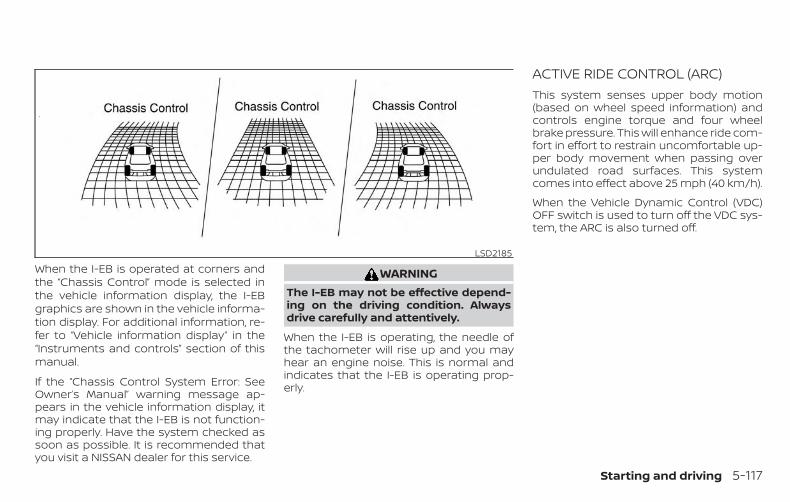
When the I-EB is operated at corners andthe “Chassis Control” mode is selected inthe vehicle information display, the I-EBgraphics are shown in the vehicle informa-tion display. For additional information, re-fer to “Vehicle information display” in the“Instruments and controls” section of thismanual.
If the “Chassis Control System Error: SeeOwner’s Manual” warning message ap-pears in the vehicle information display, itmay indicate that the I-EB is not function-ing properly. Have the system checked assoon as possible. It is recommended thatyou visit a NISSAN dealer for this service.
WARNINGThe I-EB may not be effective depend-ing on the driving condition. Alwaysdrive carefully and attentively.
When the I-EB is operating, the needle ofthe tachometer will rise up and you mayhear an engine noise. This is normal andindicates that the I-EB is operating prop-erly.
ACTIVE RIDE CONTROL (ARC)This system senses upper body motion(based on wheel speed information) andcontrols engine torque and four wheelbrake pressure. This will enhance ride com-fort in effort to restrain uncomfortable up-per body movement when passing overundulated road surfaces. This systemcomes into effect above 25 mph (40 km/h).
When the Vehicle Dynamic Control (VDC)OFF switch is used to turn off the VDC sys-tem, the ARC is also turned off.
LSD2185
Starting and driving 5-117
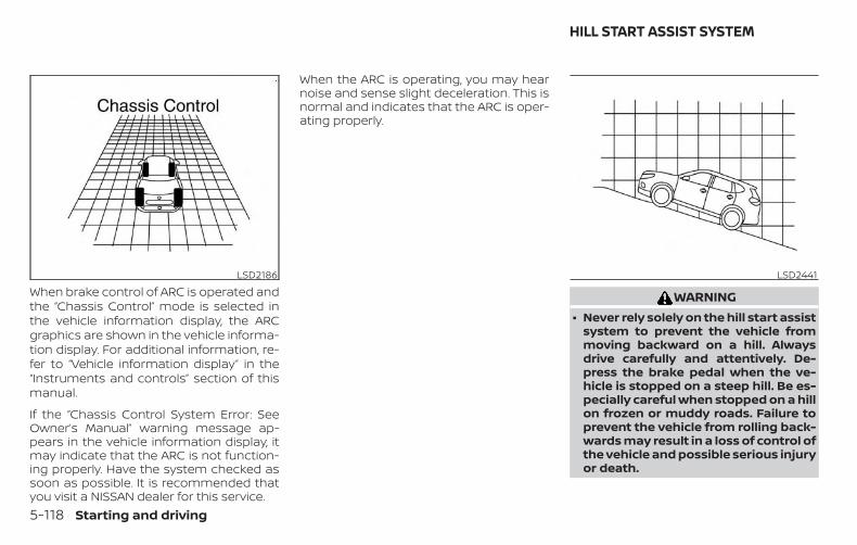
When brake control of ARC is operated andthe “Chassis Control” mode is selected inthe vehicle information display, the ARCgraphics are shown in the vehicle informa-tion display. For additional information, re-fer to “Vehicle information display” in the“Instruments and controls” section of thismanual.
If the “Chassis Control System Error: SeeOwner’s Manual” warning message ap-pears in the vehicle information display, itmay indicate that the ARC is not function-ing properly. Have the system checked assoon as possible. It is recommended thatyou visit a NISSAN dealer for this service.
When the ARC is operating, you may hearnoise and sense slight deceleration. This isnormal and indicates that the ARC is oper-ating properly.
WARNING∙ Never rely solely on the hill start assist
system to prevent the vehicle frommoving backward on a hill. Alwaysdrive carefully and attentively. De-press the brake pedal when the ve-hicle is stopped on a steep hill. Be es-pecially careful when stopped on a hillon frozen or muddy roads. Failure toprevent the vehicle from rolling back-wards may result in a loss of control ofthe vehicle and possible serious injuryor death.
LSD2186 LSD2441
HILL START ASSIST SYSTEM
5-118 Starting and driving

∙ The hill start assist system is not de-signed to hold the vehicle at a stand-still on a hill. Depress the brake pedalwhen the vehicle is stopped on asteep hill. Failure to do so may causethe vehicle to roll backwards and mayresult in a collision or serious personalinjury.
∙ The hill start assist may not preventthe vehicle from rolling backwards ona hill under all load or road conditions.Always be prepared to depress thebrake pedal to prevent the vehiclefrom rolling backwards. Failure to doso may result in a collision or seriouspersonal injury.
When the vehicle is stopped on a hill, the hillstart assist system automatically keepsthe brakes applied. This helps prevent thevehicle from rolling backward in the time ittakes the driver to release the brake pedaland apply the accelerator.
Hill start assist will operate automaticallyunder the following conditions:
∙ The shift lever is moved to a forward orreverse gear.
∙ The vehicle is stopped completely on ahill by applying the brake.
The maximum holding time is 2 seconds.After 2 seconds the vehicle will begin to rollback and hill start assist will stop operatingcompletely.
Hill start assist will not operate when theshift lever is moved to N (Neutral) or P (Park)or on a flat and level road.
The RSS sounds a tone to inform the driverof obstacles near the bumper.
When the “DISPLAY” key is on, the sonarview will automatically appear in thetouch-screen display. An additional view ofthe sonar status will appear in the vehicleinformation display for reference.
LSD3247
REAR SONAR SYSTEM (RSS) (if soequipped)
Starting and driving 5-119

WARNING∙ The RSS is a convenience but it is not a
substitute for proper parking.
∙ The driver is always responsible forsafety during parking and other ma-neuvers. Always look around andcheck that it is safe to do so beforeparking.
∙ Read and understand the limitationsof the RSS as contained in this section.The colors of the corner sonar indica-tor and the distance guide lines in therear view indicate different distancesto the object.
∙ Inclement weather or ultrasonicsources such as an automatic carwash, a truck’s compressed-airbrakes or a pneumatic drill may affectthe function of the system; this mayinclude reduced performance or afalse activation.
∙ This function is designed as an aid tothe driver in detecting large station-ary objects to help avoid damagingthe vehicle.
∙ The system is not designed to preventcontact with small or moving objects.Always move slowly. The system willnot detect small objects below thebumper, and may not detect objectsclose to the bumper or on the ground.
∙ The system may not detect the fol-lowing objects: fluffy objects such assnow, cloth, cotton, glass, wool, etc.;thin objects such as rope, wire andchain, etc.; or wedge-shaped objects.
If your vehicle sustains damage to thebumper fascia, leaving it misaligned orbent, the sensing zone may be alteredcausing inaccurate measurement of ob-stacles or false alarms.
CAUTION∙ Excessive noise (such as audio system
volume or an open vehicle window)will interfere with the tone and it maynot be heard.
∙ Keep the sonar sensors (located onthe bumper fascia) free from snow, iceand large accumulations of dirt. Donot clean the sensors with sharp ob-jects. If the sensors are covered, theaccuracy of the sonar function will bediminished.
SYSTEM OPERATIONThe system informs with a visual and au-dible alert of rear obstacles when the shiftlever is in the R (Reverse) position.Sonar Operation Table
RR SensorRange Sound Display
P x †R o oN x †D x †
o – Display/Beep when detect† – Display on camera viewx – No Display and Beep
The system is deactivated at speeds above6 mph (10 km/h). It is reactivated at lowerspeeds.
5-120 Starting and driving
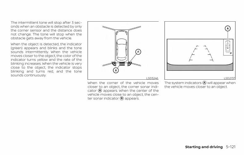
The intermittent tone will stop after 3 sec-onds when an obstacle is detected by onlythe corner sensor and the distance doesnot change. The tone will stop when theobstacle gets away from the vehicle.
When the object is detected, the indicator(green) appears and blinks and the tonesounds intermittently. When the vehiclemoves closer to the object, the color of theindicator turns yellow and the rate of theblinking increases. When the vehicle is veryclose to the object, the indicator stopsblinking and turns red, and the tonesounds continuously.
When the corner of the vehicle movescloser to an object, the corner sonar indi-cator �A appears. When the center of thevehicle moves close to an object, the cen-ter sonar indicator �B appears.
The system indicators �A will appear whenthe vehicle moves closer to an object.
LSD3246 LSD2137
Starting and driving 5-121

HOW TO ENABLE/DISABLE THESONAR SYSTEMThe system is automatically activatedwhen the ignition is in the ON position andthe shift lever is in the R (Reverse) position.
Perform the following steps to enable ordisable the sonar system:
1. Press the button until “Settings”displays in the vehicle information dis-play. Use the button to select“Driver Assistance.” Then press the OKbutton.
2. Select “Parking Aids” and press the OKbutton.
3. Select “Rear Sensor” and press the OKbutton to turn the system on or off.
– Select “Display” to display the park-ing sensor in the vehicle informationdisplay when the sonar system acti-vates.
– Select “Range” to change the sonarsystem distance to “Far,” “Mid,” or“Near.”
LSD3336
5-122 Starting and driving

SONAR LIMITATIONS
WARNINGListed below are the system limitationsfor the sonar system. Failure to operatethe vehicle in accordance with thesesystem limitations could result in seri-ous injury or death.
∙ Read and understand the limitationsof the sonar system as contained inthis section. Inclement weather mayaffect the function of the sonar sys-tem; this may include reduced perfor-mance or a false activation.
∙ The system is deactivated at speedsabove 6 mph (10 km/h). It is reacti-vated at lower speeds.
∙ Inclement weather or ultrasonicsources such as an automatic carwash, a truck’s compressed-airbrakes or a pneumatic drill may affectthe function of the system; this mayinclude reduced performance or afalse activation.
∙ The system is not designed to preventcontact with small or moving objects.Always move slowly. The system willnot detect small objects below thebumper or on the ground.
∙ The system may not detect the fol-lowing objects: fluffy objects such assnow, cloth, cotton, glass-wool, etc.;thin objects such as rope, wire andchain, etc.; or wedge-shaped objects.
∙ The system may not detect objects atspeeds above 3 mph (5 km/h) andmay not detect certain angular ormoving objects.
SYSTEM TEMPORARILYUNAVAILABLEWhen sonar blockage is detected, the sys-tem will be deactivated automatically.
The system is not available until the condi-tions no longer exist.
The sonar sensors may be blocked by tem-porary ambient conditions such as splash-ing water, mist or fog. The blocked condi-tion may also be caused by objects such asice, frost or dirt obstructing the sonar sen-sors.
Action to take:
When the above conditions no longer exist,the system will resume automatically.
Starting and driving 5-123

SYSTEM MAINTENANCEThe sonar sensors �1 are located on therear bumper. Always keep the area nearthe sonar sensors clean.
The sonar sensors may be blocked by tem-porary ambient conditions such as splash-ing water, mist or fog.
The blocked condition may also be causedby objects such as ice, frost or dirt ob-structing the sonar sensors.
Check for and remove objects obstructingthe area around the sonar sensors.
Do not attach stickers (including transpar-ent material), install accessories or applyadditional paint near the sonar sensors.
Do not strike or damage the area aroundthe sonar sensors. It is recommended thatyou visit a NISSAN dealer if the area aroundthe sonar sensors is damaged due to acollision.
FREEING A FROZEN DOOR LOCKTo prevent a door lock from freezing, applyde-icer through the key hole. If the lockbecomes frozen, heat the key before in-serting it into the key hole, or use theNISSAN Intelligent Key®.
ANTIFREEZEIn the winter when it is anticipated that thetemperature will drop below 32°F (0°C),check the antifreeze to assure proper win-ter protection. For additional information,refer to “Engine cooling system” in the “Do-it-yourself ” section of this manual.
12–VOLT BATTERYIf the 12–volt battery is not fully chargedduring extremely cold weather conditions,the battery fluid may freeze and damagethe battery. To maintain maximum effi-ciency, the 12–volt battery should bechecked regularly. For additional informa-tion, refer to “12–volt battery” in the “Do-it-yourself ” section of this manual.
LSD3334
COLD WEATHER DRIVING
5-124 Starting and driving

DRAINING OF COOLANT WATERIf the vehicle is to be left outside withoutantifreeze, drain the cooling system, includ-ing the engine block. Refill before operatingthe vehicle. For additional information, referto “Changing engine coolant” in the “Do-it-yourself ” section of this manual.
TIRE EQUIPMENT1. SUMMER tires have a tread designed to
provide superior performance on drypavement. However, the performanceof these tires will be substantially re-duced in snowy and icy conditions. Ifyou operate your vehicle on snowy oricy roads, NISSAN recommends the useof MUD & SNOW or ALL SEASON TIRESon all four wheels. It is recommendedthat you visit a NISSAN dealer for the tiretype, size, speed rating and availabilityinformation.
2. For additional traction on icy roads,studded tires may be used. However,some U.S. states and Canadian prov-inces prohibit their use. Check local,state and provincial laws before install-ing studded tires.
Skid and traction capabilities of studdedsnow tires on wet or dry surfaces may bepoorer than that of non-studded snowtires.
3. Tire chains may be used. For additionalinformation, refer to “Tire chains” in the“Do-it-yourself ” section of this manual.
SPECIAL WINTER EQUIPMENTIt is recommended that the following itemsbe carried in the vehicle during winter:
∙ A scraper and stiff-bristled brush to re-move ice and snow from the windowsand wiper blades.
∙ A sturdy, flat board to be placed underthe jack to give it firm support.
∙ A shovel to dig the vehicle out of snow-drifts.
∙ Extra washer fluid to refill thewindshield-washer fluid reservoir.
DRIVING ON SNOW OR ICE
WARNING∙ Wet ice (32°F, 0°C and freezing rain),
very cold snow or ice can be slick andvery hard to drive on. The vehicle willhave much less traction or “grip” un-der these conditions. Try to avoid driv-ing on wet ice until the road is saltedor sanded.
∙ Whatever the condition, drive withcaution. Accelerate and slow downwith care. If accelerating or down-shifting too fast, the drive wheels willlose even more traction.
∙ Allow more stopping distance underthese conditions. Braking should bestarted sooner than on dry pavement.
∙ Allow greater following distances onslippery roads.
Starting and driving 5-125

∙ Watch for slippery spots (glare ice).These may appear on an otherwiseclear road in shaded areas. If a patchof ice is seen ahead, brake beforereaching it. Try not to brake while onthe ice, and avoid any sudden steeringmaneuvers.
∙ Do not use the cruise control on slip-pery roads.
∙ Snow can trap dangerous exhaustgases under your vehicle. Keep snowclear of the exhaust pipe and fromaround your vehicle.
5-126 Starting and driving

6 In case of emergency
Hazard warning flasher switch . . . . . . . . . . . . . . . . . . 6-2Emergency hybrid system shut off . . . . . . . . . . . . . . 6-2Flat tire . . . . . . . . . . . . . . . . . . . . . . . . . . . . . . . . . . . . . . . . . . 6-3
Tire Pressure Monitoring System(TPMS). . . . . . . . . . . . . . . . . . . . . . . . . . . . . . . . . . . . . . . . 6-3Changing a flat tire . . . . . . . . . . . . . . . . . . . . . . . . . . . 6-4
Hybrid system stops operating while driving. . . . .6-11If the vehicle does not start . . . . . . . . . . . . . . . . . . . . . .6-11
Confirm battery is discharged . . . . . . . . . . . . . . . .6-11
Emergency start . . . . . . . . . . . . . . . . . . . . . . . . . . . . .6-11Jump starting . . . . . . . . . . . . . . . . . . . . . . . . . . . . . . . . . . 6-12Push starting . . . . . . . . . . . . . . . . . . . . . . . . . . . . . . . . . . . 6-14If your vehicle overheats . . . . . . . . . . . . . . . . . . . . . . . . 6-15Towing your vehicle . . . . . . . . . . . . . . . . . . . . . . . . . . . . 6-16
Towing recommended by NISSAN . . . . . . . . . . . 6-16Vehicle recovery (freeing a stuckvehicle) . . . . . . . . . . . . . . . . . . . . . . . . . . . . . . . . . . . . . . 6-18
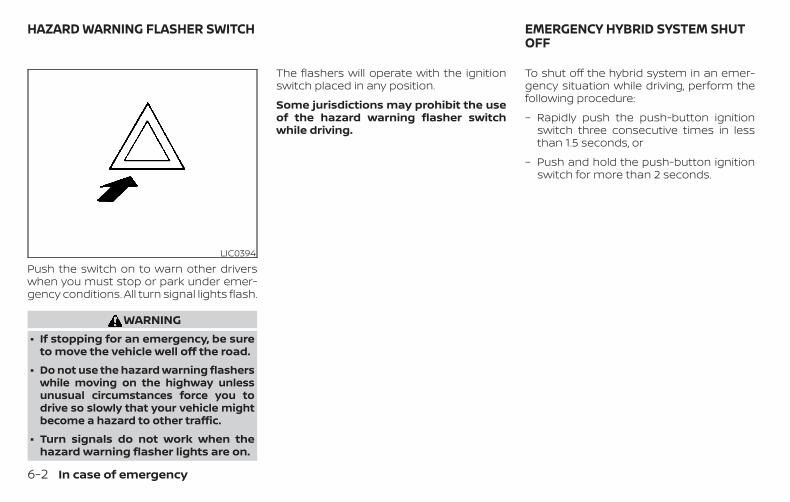
Push the switch on to warn other driverswhen you must stop or park under emer-gency conditions. All turn signal lights flash.
WARNING∙ If stopping for an emergency, be sure
to move the vehicle well off the road.
∙ Do not use the hazard warning flasherswhile moving on the highway unlessunusual circumstances force you todrive so slowly that your vehicle mightbecome a hazard to other traffic.
∙ Turn signals do not work when thehazard warning flasher lights are on.
The flashers will operate with the ignitionswitch placed in any position.
Some jurisdictions may prohibit the useof the hazard warning flasher switchwhile driving.
To shut off the hybrid system in an emer-gency situation while driving, perform thefollowing procedure:
– Rapidly push the push-button ignitionswitch three consecutive times in lessthan 1.5 seconds, or
– Push and hold the push-button ignitionswitch for more than 2 seconds.
LIC0394
HAZARD WARNING FLASHER SWITCH EMERGENCY HYBRID SYSTEM SHUTOFF
6-2 In case of emergency

TIRE PRESSURE MONITORINGSYSTEM (TPMS)This vehicle is equipped with Tire PressureMonitoring System (TPMS). It monitors tirepressure of all tires except the spare. Whenthe low tire pressure warning light is lit, andthe “Tire Pressure Low - Add Air” warningappears in the vehicle information display,one or more of your tires is significantlyunder-inflated. If equipped, the system alsodisplays pressure of all tires (except thespare tire) on the display screen by sendinga signal from a sensor that is installed ineach wheel. If the vehicle is being drivenwith low tire pressure, the TPMS will acti-vate and warn you of it by the low tire pres-sure warning light. This system will activateonly when the vehicle is driven at speedsabove 16 mph (25 km/h). For additional in-formation, refer to “Warning lights, indicatorlights and audible reminders” in “Instru-ments and controls” section and the “TirePressure Monitoring System (TPMS)” in the“Starting and driving” sections of thismanual.
WARNING∙ Radio waves could adversely affect
electric medical equipment. Thosewho use a pacemaker should contactthe electric medical equipmentmanufacturer for the possible influ-ences before use.
∙ If the low tire pressure warning lightilluminates while driving, avoid sud-den steering maneuvers or abruptbraking, reduce vehicle speed, pull offthe road to a safe location and stopthe vehicle as soon as possible. Driv-ing with under-inflated tires may per-manently damage the tires and in-crease the likelihood of tire failure.Serious vehicle damage could occurand may lead to an accident and couldresult in serious personal injury.Check the tire pressure for all fourtires. Adjust the tire pressure to therecommended COLD tire pressureshown on the Tire and Loading Infor-mation label to turn the low tire pres-sure warning light OFF. If the light stillilluminates while driving after adjust-ing the tire pressure, a tire may be flator the TPMS may be malfunctioning. Ifyou have a flat tire, replace it with a
spare tire as soon as possible, If no tireis flat and all tires are properly in-flated, have the vehicle checked. It isrecommended that you visit a NISSANdealer for this service.
∙ When replacing a wheel without TPMSsuch as the spare tire, TPMS will notfunction and the low tire pressurewarning light will flash for approxi-mately 1 minute. The light will remainon after 1 minute. Have your tires re-placed and/or TPMS system reset assoon as possible. It is recommendedthat you visit a NISSAN dealer forthese services.
∙ Replacing tires with those not origi-nally specified by NISSAN could affectthe proper operation of the TPMS.
∙ Do not inject any tire liquid or aerosoltire sealant into the tires, as this maycause a malfunction of the tire pres-sure sensors.
FLAT TIRE
In case of emergency 6-3

CHANGING A FLAT TIREIf you have a flat tire, follow the instructionsbelow:
Stopping the vehicle1. Safely move the vehicle off the road and
away from traffic.
2. Turn on the hazard warning flashers.
3. Park on a level surface and apply theparking brake. Move the shift lever to P(Park).
4. Turn off the hybrid system.
5. Raise the hood to warn other trafficand to signal professional road assis-tance personnel that you need assis-tance.
6. Have all passengers get out of the ve-hicle and stand in a safe place, awayfrom traffic and clear of the vehicle.
WARNING∙ Make sure the parking brake is se-
curely applied and the shift lever isshifted into P (Park).
∙ Never change tires when the vehicle ison a slope, ice or slippery areas. This ishazardous.
∙ Never change tires if oncoming trafficis close to your vehicle. Wait for pro-fessional road assistance.
A. BlocksB. Flat tire
Blocking wheelsPlace suitable blocks at both the front andback of the wheel diagonally opposite theflat tire to prevent the vehicle from movingwhen it is jacked up.
WARNINGBe sure to block the wheel as the vehiclemay move and result in personal injury.
LCE2142
6-4 In case of emergency

Getting the spare tire and toolsOpen the rear liftgate. Pull up on the handleto lift the luggage board. For additional in-formation, refer to “Storage” in the “Instru-ments and controls” section of this manual.
1. The jack and tool kit are located in thestorage compartment to the left.
2. Remove the storage door by pressingthe two release tabs �A simultane-ously.
3. Unhook the clips �B restraining the jackand tool kit.
4. Remove the tool kit.
5. Remove the jack.
LCE2314 LCE2315 LCE2437
In case of emergency 6-5

6. Lift the floorboard. 7. Use the slotted end of the jack tool toremove the clips that are holding thefloor board in place by pressing thecenter pin downwards.
8. To loosen the bolt, turn counterclock-wise.
9. Once loosened, remove the bolt.
10. Remove the spare tire.
LCE2376 LCE2313 LCE2316
6-6 In case of emergency

Changing the spare tire withBOSE® sub-woofer (if soequipped)
1. To loosen the bolt, turn counterclock-wise.
2. Once loosened, remove the bolt.
3. Place the sub-woofer in the upper rightcorner of the storage compartment,leaning against the rear row passengerside seat.
4. Remove the spare tire.
5. After removing the spare tire, returnthe sub-woofer to the cargo area.
6. Tighten the bolt in the center of thesub-woofer.
NOTE:
The sub-woofer will be held loosely inplace with the bolt while the spare tire isin use. Using the sub-woofer while thespare tire is in use could further loosen orcause damage to the sub-woofer.
7. Once the flat tire has been replaced,return the spare tire to the cargo area.
8. Secure the spare tire and sub-wooferin place with the bolt.
LCE2318 LCE2320
In case of emergency 6-7

Jacking up vehicle and removingthe damaged tire
WARNING∙ Never get under the vehicle while it is
supported only by the jack. If it is nec-essary to work under the vehicle, sup-port it with safety stands.
∙ Use only the jack provided with yourvehicle to lift the vehicle. Do not usethe jack provided with your vehicle onother vehicles. The jack is designedfor lifting only your vehicle during atire change.
∙ Use the correct jack-up points. Neveruse any other part of the vehicle forjack support.
∙ Never jack up the vehicle more thannecessary.
∙ Never use blocks on or under the jack.
∙ Do not start or run the hybrid systemwhile vehicle is on the jack. It maycause the vehicle to move. This is es-pecially true for vehicles with limitedslip differentials.
LCE2325
6-8 In case of emergency

∙ Do not allow passengers to stay in thevehicle while it is on the jack.
∙ Never run the engine with a wheel(s)off the ground. It may cause the ve-hicle to move.
Always refer to the illustrations for the cor-rect placement and jack-up points for yourspecific vehicle model and jack type.
Carefully read the caution label attachedto the jack body and the following in-structions.
1. Loosen each wheel nut 1 or 2 turns byturning counterclockwise with thewheel nut wrench. Do not remove thewheel nuts until the tire is off theground.
2. Place the jack directly under the jack-uppoint as illustrated so the top of the jackcontacts the vehicle at the jack-up point.Align the jack head between the 2notches in the front or the rear asshown. Also fit the groove of the jackhead between the notches as shown.
The jack should be used on firm andlevel ground.
3. To lift the vehicle, securely hold the jacklever and rod with both hands. Carefullyraise the vehicle until the tire clears theground. Remove the wheel nuts, andthen remove the tire.
SCE0002
In case of emergency 6-9
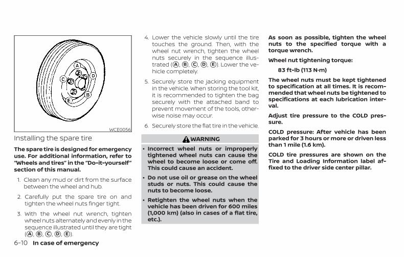
Installing the spare tireThe spare tire is designed for emergencyuse. For additional information, refer to“Wheels and tires” in the “Do-it-yourself”section of this manual.
1. Clean any mud or dirt from the surfacebetween the wheel and hub.
2. Carefully put the spare tire on andtighten the wheel nuts finger tight.
3. With the wheel nut wrench, tightenwheel nuts alternately and evenly in thesequence illustrated until they are tight(�A , �B , �C , �D , �E ).
4. Lower the vehicle slowly until the tiretouches the ground. Then, with thewheel nut wrench, tighten the wheelnuts securely in the sequence illus-trated (�A , �B , �C , �D , �E ). Lower the ve-hicle completely.
5. Securely store the jacking equipmentin the vehicle. When storing the tool kit,it is recommended to tighten the bagsecurely with the attached band toprevent movement of the tools, other-wise noise may occur.
6. Securely store the flat tire in the vehicle.
WARNING∙ Incorrect wheel nuts or improperly
tightened wheel nuts can cause thewheel to become loose or come off.This could cause an accident.
∙ Do not use oil or grease on the wheelstuds or nuts. This could cause thenuts to become loose.
∙ Retighten the wheel nuts when thevehicle has been driven for 600 miles(1,000 km) (also in cases of a flat tire,etc.).
As soon as possible, tighten the wheelnuts to the specified torque with atorque wrench.
Wheel nut tightening torque:
83 ft-lb (113 N·m)
The wheel nuts must be kept tightenedto specification at all times. It is recom-mended that wheel nuts be tightened tospecifications at each lubrication inter-val.
Adjust tire pressure to the COLD pres-sure.
COLD pressure: After vehicle has beenparked for 3 hours or more or driven lessthan 1 mile (1.6 km).
COLD tire pressures are shown on theTire and Loading Information label af-fixed to the driver side center pillar.
WCE0056
6-10 In case of emergency

WARNING∙ If the hybrid system stops operating
while driving, the power assist for thebrakes and steering will not work.Braking and steering will be harder.
∙ If the hybrid system stops operatingwhile driving, do not open any dooruntil the vehicle comes to a completestop. Opening a door will lock thesteering wheel. This may cause thedriver to lose control of the vehicleand could result in serious vehicledamage or personal injury.
The hybrid system may stop operatingwhile driving if the high-voltage battery be-comes discharged, the 12-volt battery be-comes discharged or the fuel tank isempty. If the hybrid system stops operat-ing while driving, perform the following:
1. Reduce your speed gradually. Pull to theside of the road to a safe area.
2. Turn on the hazard warning flashers.
3. Set the push-button ignition switch atOFF, and try to start the hybrid system.
4. If the hybrid system will not start, referto the “If the vehicle does not start” inthis section of the manual.
Before attempting to jump start the ve-hicle, make sure the fuel tank is not emptyand the correct starting procedure is fol-lowed. For additional information, refer to“Starting the NISSAN PURE DRIVE® HybridSystem” in the “Starting and driving” sectionof this manual. Do not drive the vehicle onbattery power only if the fuel tank is empty.The Li-ion battery will become dischargedand the hybrid system will turn off.
CONFIRM BATTERY ISDISCHARGEDConfirm the battery is discharged by push-ing the ignition switch to the ON position.Confirm the instrument cluster or headlights come on at the normal brightnesslevels or that other accessories such as theaudio system come on. Push the ignitionswitch to turn the hybrid system on.
If any of the following conditions occur, the12-volt battery might discharge:
∙ The instrument cluster and/or head-lights are not normal brightness.
∙ Audio accessories cannot be turned on.
∙ The hybrid system does not becomeREADY to drive mode.
∙ The ignition switch cannot be placed inthe ON position.
Check the following if you notice any of theabove conditions:
1. Check that the 12-volt battery terminalsare tight and clean. For additional infor-mation, refer to “12-volt battery” in the“Do-it-yourself ” section of this manual. Ifthe 12-volt battery terminals are loose,it is recommended that you visit aNISSAN dealer.
2. If the 12-volt battery terminals are tightand clean, try to jump start the vehicle.For additional information, refer to“Jump starting” in this section.
EMERGENCY STARTWhen the hybrid system cannot be started,the following procedure can be used if thehybrid system and push-button ignitionswitch function normally:
1. Put the transmission in P (Park) posi-tion.
2. Push the ignition switch to the ON po-sition.
3. Depress the brake pedal.
HYBRID SYSTEM STOPS OPERATINGWHILE DRIVING
IF THE VEHICLE DOES NOT START
In case of emergency 6-11
4. Push and hold the ignition switch forabout 90 seconds. Even if the hybridsystem starts using this procedure, thesystem may be malfunctioning. Do notcontinue to use this emergency proce-dure to start the system. Have the ve-hicle checked. It is recommended thatyou visit a NISSAN dealer for this ser-vice.
If the hybrid system still does not start, it isrecommended that you visit a NISSANdealer for this service.
Jump starting provides power to the12–volt system to allow the electrical sys-tems to operate. The electrical systemsmust be operating to allow the Li-ion bat-tery to be charged. Jump starting does notcharge the Li-ion battery.
To start the hybrid system with a boosterbattery, the instructions and precautionsbelow must be followed.
WARNING∙ The engine may start at any time
without warning when the ignition ison and the hybrid system is in theREADY mode. When jump startingkeep your hands, clothing, hair andtools away from fans, belts and anyother parts that can move to avoidpersonal injury.
∙ If done incorrectly, jump starting canlead to a 12–volt battery explosion, re-sulting in severe injury or death. Itcould also damage your vehicle.
∙ Explosive hydrogen gas is alwayspresent in the vicinity of the battery.Keep all sparks and flames away fromthe battery. Make sure that the venttube is mounted.
∙ Do not allow battery fluid to come intocontact with eyes, skin, clothing orpainted surfaces. Battery fluid is acorrosive sulfuric acid solution whichcan cause severe burns. If the fluidshould come into contact with any-thing, immediately flush the con-tacted area with water.
∙ Keep 12–volt battery out of the reachof children.
∙ The booster battery must be rated at12 volts. Use of an improperly ratedbattery can damage your vehicle.
∙ Whenever working on or near a bat-tery, always wear suitable eye protec-tors (for example, goggles or indus-trial safety spectacles) and removerings, metal bands, or any other jew-elry. Do not lean over the batterywhen jump starting.
∙ Do not attempt to jump start a frozenbattery. It could explode and causeserious injury.
∙ Your vehicle has an automatic enginecooling fan. It could come on at anytime. Keep hands and other objectsaway from it.
JUMP STARTING
6-12 In case of emergency

∙ Always follow the instructions below.Failure to do so could result in dam-age to the charging system and causepersonal injury.
CAUTIONDo not attempt to jump start a hybridvehicle as a booster vehicle.
1. Locate the fusible link box behind theengine air cleaner.
2. Push the tab in and lift up �A to removethe lid and expose the remote positivebattery terminal �B .
3. If the booster battery is in another ve-hicle position the two vehicles to bringtheir batteries near each other.
Do not allow the two vehicles totouch.
4. Apply the parking brake. Move the shiftlever to P (Park). Switch off all unneces-sary electrical systems (lights, heater,air conditioner, etc.).
5. Connect jumper cables in the se-quence illustrated (�B , �C , �D , �E ).
LCE2170
In case of emergency 6-13

CAUTION∙ Always connect positive (�) to posi-
tive (�) and negative (�) to bodyground (for example, strut mountingbolt, engine lift bracket, etc.) — not tothe battery.
∙ Make sure the jumper cables do nottouch moving parts in the enginecompartment and that the cableclamps do not contact any othermetal.
∙ Do not keep the starter motor en-gaged for more than 10 seconds. If theengine does not start right away,place the ignition switch in the OFFposition and wait 10 seconds.
6. Start the engine of the booster vehicleand let it run for a few minutes.
7. Hold down the brake pedal and pressthe START button. The vehicle instru-ments and gauges will light up, and thegreen "READY" light will come ON. Foradditional information, refer to “Warn-ing lights, indicator lights and audiblereminders” in the “Instrument and con-trols” section of this manual.
CAUTIONIf the green READY light does not comeon, press the START button to turn thehybrid system OFF. Carefully discon-nect the negative cable then the posi-tive cable. Have vehicle taken to dealer-ship for repair.
8. After the green READY light in the me-ter display comes on, carefully discon-nect the negative cable and then thepositive cable.
CAUTION∙ Continuously Variable Transmission
(CVT) models cannot be push-startedor tow-started. Attempting to do somay cause transmission damage.
∙ Do not push start this vehicle. Thethree-way catalyst may be damaged.
PUSH STARTING
6-14 In case of emergency
WARNING∙ Do not continue to drive if your vehicle
overheats. Doing so could cause en-gine damage or a vehicle fire.
∙ To avoid the danger of being scalded,never remove the radiator or coolantreservoir cap while the engine is stillhot. When the radiator or coolant res-ervoir cap is removed, pressurized hotwater will spurt out, possibly causingserious injury.
∙ Do not open the hood if steam is com-ing out.
If your vehicle is overheating (indicated bythe “Hybrid System Overheated Stop Ve-hicle” vehicle information display warning),or if you feel a lack of engine power, detectabnormal noise, etc. take the followingsteps.
1. Move the vehicle safely off the road, ap-ply the parking brake and move theshift lever to P (Park).
Do not turn off the NISSAN PUREDRIVE® Hybrid System.
2. Turn off the air conditioner. Open all thewindows, move the heater or air condi-tioner temperature control to maxi-mum hot and fan control to highspeed.
3. Get out of the vehicle. Look and listenfor steam or coolant escaping from theradiator before opening the hood. (Ifsteam or coolant is escaping, turn offthe hybrid system.) Do not open thehood further until no steam or coolantcan be seen.
4. Open the engine hood.
WARNINGIf steam or water is coming from theengine, stand clear to prevent gettingburned.
5. Also check if the cooling fan is running.The radiator hoses and radiator shouldnot leak water. If the coolant is leakingor the cooling fan does not run, stopthe hybrid system.
6. Visually check drive belts for damageor looseness. Also check if the coolingfan is running. The radiator hoses andradiator should not leak water. If cool-ant is leaking, the water pump belt ismissing or loose, or the cooling fandoes not run, stop the hybrid system.
WARNINGBe careful not to allow your hands, hair,jewelry or clothing to come into contactwith, or get caught in, engine belts orthe engine cooling fan. The engine cool-ing fan can start at any time.
7. After the engine cools down, check thecoolant level in the engine coolant res-ervoir tank with the engine running. Addcoolant to the engine coolant reservoirtank if necessary. Have your vehicle re-paired. It is recommended that you visita NISSAN dealer for this service.
IF YOUR VEHICLE OVERHEATS
In case of emergency 6-15

When towing your vehicle, all jurisdictionaland local regulations for towing must befollowed. Incorrect towing equipmentcould damage your vehicle. Towing in-structions are available from a NISSANdealer. Local service operators are gener-ally familiar with the applicable laws andprocedures for towing. To assure propertowing and to prevent accidental damageto your vehicle, NISSAN recommends hav-ing a service operator tow your vehicle. It isadvisable to have the service operatorcarefully read the following precautions:
WARNING∙ Never ride in a vehicle that is being
towed.
∙ Never get under your vehicle after ithas been lifted by a tow truck.
CAUTION∙ When towing, make sure that the
transmission, axles, steering systemand powertrain are in working condi-tion. If any of these conditions apply,dollies or a flatbed tow truck must beused.
∙ Always attach safety chains beforetowing.
For additional information, refer to “Flattowing for all-wheel drive vehicle” in the“Technical and consumer information” sec-tion of this manual.
TOWING RECOMMENDED BYNISSANNISSAN recommends towing your vehiclebased upon the type of drivetrain. For addi-tional information, refer to the diagrams inthis section to ensure that your vehicle isproperly towed.
TOWING YOUR VEHICLE
6-16 In case of emergency

All-Wheel Drive (AWD) models withContinuously VariableTransmission (CVT)NISSAN recommends that towing dolliesbe used when towing your vehicle or placethe vehicle on a flatbed truck as illustrated.
CAUTIONNever tow All-Wheel Drive (AWD) mod-els equipped with a Continuously Vari-able Transmission (CVT) with any of thewheels on the ground as this may causeserious and expensive damage to thetransfer case and transmission.
LCE2238
In case of emergency 6-17

Front-Wheel Drive models withContinuously VariableTransmission (CVT)NISSAN recommends that your vehicle betowed with the driving (front) wheels off theground or place the vehicle on a flatbedtruck as illustrated.
CAUTION∙ Never tow CVT models with the front
wheels on the ground or four wheelson the ground (forward or backward),as this may cause serious and expen-sive damage to the transmission. If itis necessary to tow the vehicle withthe rear wheels raised always usetowing dollies under the front wheels.
∙ When towing CVT models with therear wheels on the ground or on tow-ing dollies:
– Place the ignition switch in the OFFposition, and secure the steeringwheel in a straight-ahead positionwith a rope or similar device. Neversecure the steering wheel by plac-ing the ignition switch in the LOCKposition. This may damage thesteering lock mechanism (formodels with a steering lockmechanism).
VEHICLE RECOVERY (freeing astuck vehicle)
WARNINGTo avoid vehicle damage, serious per-sonal injury or death when recovering astuck vehicle:
∙ Contact a professional towing serviceto recover the vehicle if you have anyquestions regarding the recoveryprocedure.
∙ Tow chains or cables must be at-tached only to main structural mem-bers of the vehicle.
∙ Do not use the vehicle tie-downs totow or free a stuck vehicle.
LCE2239
6-18 In case of emergency

∙ Only use devices specifically designedfor vehicle recovery and follow themanufacturer’s instructions.
∙ Always pull the recovery devicestraight out from the front of the ve-hicle. Never pull at an angle.
∙ Route recovery devices so they do nottouch any part of the vehicle exceptthe attachment point.
If your vehicle is stuck in sand, snow, mud,etc., use a tow strap or other device de-signed specifically for vehicle recovery. Al-ways follow the manufacturer’s instruc-tions for the recovery device.
Rocking a stuck vehicle
WARNING∙ Stand clear of a stuck vehicle.
∙ Do not spin your tires at high speed.This could cause them to explode andresult in serious injury. Parts of yourvehicle could also overheat and bedamaged.
If your vehicle is stuck in sand, snow, mud,etc., use the following procedure:
1. Turn off the Vehicle Dynamic Control(VDC) system.
2. Make sure the area in front and behindthe vehicle is clear of obstructions.
3. Turn the steering wheel right and left toclear an area around the front tires.
4. Slowly rock the vehicle forward andbackward.
∙ Shift back and forth between R (Re-verse) and D (Drive).
∙ Apply the accelerator as little as pos-sible to maintain the rocking motion.
∙ Release the accelerator pedal beforeshifting between R (Reverse) and D(Drive).
∙ Do not spin the tires above 34 mph(55 km/h).
5. If the vehicle cannot be freed after afew tries, contact a professional towingservice to remove the vehicle.
In case of emergency 6-19

MEMO
6-20 In case of emergency
7 Appearance and care
Cleaning exterior . . . . . . . . . . . . . . . . . . . . . . . . . . . . . . . . 7-2Washing. . . . . . . . . . . . . . . . . . . . . . . . . . . . . . . . . . . . . . 7-2Waxing . . . . . . . . . . . . . . . . . . . . . . . . . . . . . . . . . . . . . . . 7-2Removing spots . . . . . . . . . . . . . . . . . . . . . . . . . . . . . . 7-3Underbody . . . . . . . . . . . . . . . . . . . . . . . . . . . . . . . . . . . 7-3Glass . . . . . . . . . . . . . . . . . . . . . . . . . . . . . . . . . . . . . . . . . 7-3Aluminum alloy wheels . . . . . . . . . . . . . . . . . . . . . . . 7-3Chrome parts . . . . . . . . . . . . . . . . . . . . . . . . . . . . . . . . 7-3Tire dressings . . . . . . . . . . . . . . . . . . . . . . . . . . . . . . . . 7-3
Cleaning interior. . . . . . . . . . . . . . . . . . . . . . . . . . . . . . . . . 7-4Lithium-ion (Li-ion) battery air vent . . . . . . . . . . . 7-5
Air fresheners . . . . . . . . . . . . . . . . . . . . . . . . . . . . . . . . 7-5Power moonroof (if so equipped) . . . . . . . . . . . . . 7-5Floor mats (if so equipped) . . . . . . . . . . . . . . . . . . . 7-6Seat belts . . . . . . . . . . . . . . . . . . . . . . . . . . . . . . . . . . . . 7-7Cleaning the seat tracks. . . . . . . . . . . . . . . . . . . . . . 7-7
Corrosion protection . . . . . . . . . . . . . . . . . . . . . . . . . . . . 7-7Most common factors contributing tovehicle corrosion . . . . . . . . . . . . . . . . . . . . . . . . . . . . . 7-7Environmental factors influence therate of corrosion. . . . . . . . . . . . . . . . . . . . . . . . . . . . . . 7-7Protect your vehicle from corrosion . . . . . . . . . . 7-8

In order to maintain the appearance ofyour vehicle, it is important to take propercare of it.
To protect the paint surfaces, wash yourvehicle as soon as you can:
∙ After a rainfall to prevent possible dam-age from acid rain.
∙ After driving on coastal roads.
∙ When contaminants such as soot, birddroppings, tree sap, metal particles orbugs get on the paint surface.
∙ When dust or mud builds up on the sur-face.
Whenever possible, store or park your ve-hicle inside a garage or in a covered area.
When it is necessary to park outside, park ina shady area or protect the vehicle with abody cover.
Be careful not to scratch the paint sur-face when putting on or removing thebody cover.
WASHINGWash dirt off with a wet sponge and plentyof water. Clean the vehicle thoroughly us-ing a mild soap, a special vehicle soap orgeneral purpose dishwashing liquid mixedwith clean, lukewarm (never hot) water.
CAUTION∙ Do not use car washes that use acid in
the detergent. Some car washes, es-pecially brushless ones, use someacid for cleaning. The acid may reactwith some plastic vehicle compo-nents, causing them to crack. Thiscould affect their appearance, andalso could cause them not to functionproperly. Always check with your carwash to confirm that acid is not used.
∙ Do not wash the vehicle with stronghousehold soap, strong chemical de-tergents, gasoline or solvents.
∙ Do not wash the vehicle in direct sun-light or while the vehicle body is hot,as the surface may becomewater-spotted.
∙ Avoid using tight-napped or roughcloths, such as washing mitts. Caremust be taken when removingcaked-on dirt or other foreign sub-stances so the paint surface is notscratched or damaged.
Rinse the vehicle thoroughly with plenty ofclean water.
Inside edges, seams and folds on thedoors, hatches and hood are particularlyvulnerable to the effects of road salt. There-fore, these areas must be cleaned regularly.Take care that the drain holes in the loweredge of the door are open. Spray waterunder the body and in the wheel wells toloosen the dirt and wash away road salt.
A damp chamois can be used to dry thevehicle to avoid water spots.
WAXINGRegular waxing protects the paint surfaceand helps retain new vehicle appearance.Polishing is recommended to removebuilt-up wax residue and to avoid a weath-ered appearance before re-applying wax.
A NISSAN dealer can assist you in choosingthe proper product.
CLEANING EXTERIOR
7-2 Appearance and care
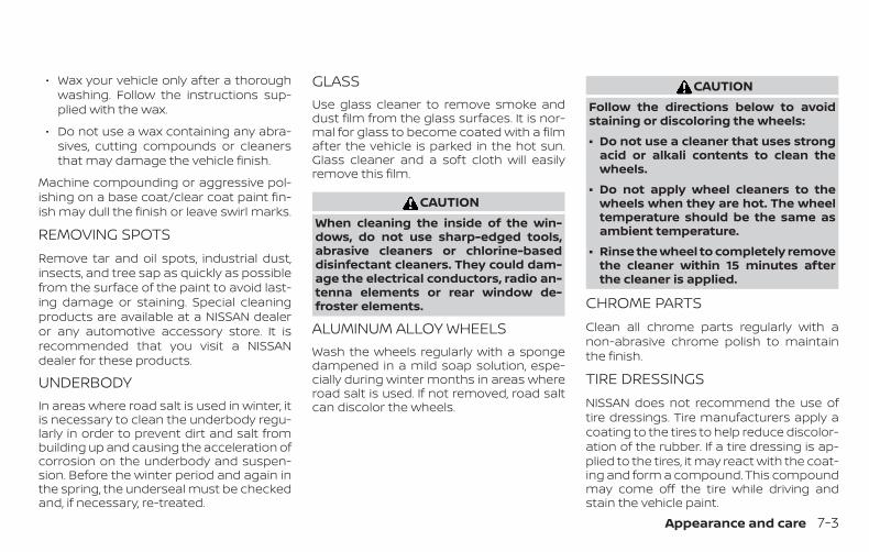
∙ Wax your vehicle only after a thoroughwashing. Follow the instructions sup-plied with the wax.
∙ Do not use a wax containing any abra-sives, cutting compounds or cleanersthat may damage the vehicle finish.
Machine compounding or aggressive pol-ishing on a base coat/clear coat paint fin-ish may dull the finish or leave swirl marks.
REMOVING SPOTSRemove tar and oil spots, industrial dust,insects, and tree sap as quickly as possiblefrom the surface of the paint to avoid last-ing damage or staining. Special cleaningproducts are available at a NISSAN dealeror any automotive accessory store. It isrecommended that you visit a NISSANdealer for these products.
UNDERBODYIn areas where road salt is used in winter, itis necessary to clean the underbody regu-larly in order to prevent dirt and salt frombuilding up and causing the acceleration ofcorrosion on the underbody and suspen-sion. Before the winter period and again inthe spring, the underseal must be checkedand, if necessary, re-treated.
GLASSUse glass cleaner to remove smoke anddust film from the glass surfaces. It is nor-mal for glass to become coated with a filmafter the vehicle is parked in the hot sun.Glass cleaner and a soft cloth will easilyremove this film.
CAUTIONWhen cleaning the inside of the win-dows, do not use sharp-edged tools,abrasive cleaners or chlorine-baseddisinfectant cleaners. They could dam-age the electrical conductors, radio an-tenna elements or rear window de-froster elements.
ALUMINUM ALLOY WHEELSWash the wheels regularly with a spongedampened in a mild soap solution, espe-cially during winter months in areas whereroad salt is used. If not removed, road saltcan discolor the wheels.
CAUTIONFollow the directions below to avoidstaining or discoloring the wheels:
∙ Do not use a cleaner that uses strongacid or alkali contents to clean thewheels.
∙ Do not apply wheel cleaners to thewheels when they are hot. The wheeltemperature should be the same asambient temperature.
∙ Rinse the wheel to completely removethe cleaner within 15 minutes afterthe cleaner is applied.
CHROME PARTSClean all chrome parts regularly with anon-abrasive chrome polish to maintainthe finish.
TIRE DRESSINGSNISSAN does not recommend the use oftire dressings. Tire manufacturers apply acoating to the tires to help reduce discolor-ation of the rubber. If a tire dressing is ap-plied to the tires, it may react with the coat-ing and form a compound. This compoundmay come off the tire while driving andstain the vehicle paint.
Appearance and care 7-3

If you choose to use a tire dressing, take thefollowing precautions:
∙ Use a water-based tire dressing. Thecoating on the tire dissolves more easilythan with an oil-based tire dressing.
∙ Apply a light coat of tire dressing to helpprevent it from entering the tiretread/grooves (where it would be diffi-cult to remove).
∙ Wipe off excess tire dressing using a drytowel. Make sure the tire dressing iscompletely removed from the tiretread/grooves.
∙ Allow the tire dressing to dry as recom-mended by the tire dressing manufac-turer.
Occasionally remove loose dust from theinterior trim, plastic parts and seats using avacuum cleaner or soft bristled brush. Wipethe vinyl and leather (if so equipped) sur-faces with a clean, soft cloth dampened inmild soap solution, then wipe clean with adry, soft cloth.
Regular care and cleaning is required inorder to maintain the appearance of theleather (if so equipped).
Before using any fabric protector, read themanufacturer’s recommendations. Somefabric protectors contain chemicals thatmay stain or bleach the seat material.
Use a cloth dampened only with water toclean the meter and gauge lens.
WARNINGDo not use water or acidic cleaners (hotsteam cleaners) on the seat. This candamage the seat or occupant classifi-cation sensor. This can also affect theoperation of the air bag system and re-sult in serious personal injury.
CAUTION∙ Never use benzine, thinner or any
similar material.
∙ Small dirt particles can be abrasiveand damaging to leather surfacesand should be removed promptly. Donot use saddle soap, car waxes, pol-ishes, oils, cleaning fluids, solvents,detergents or ammonia-based clean-ers as they may damage the leather’snatural finish.
∙ Never use fabric protectors unlessrecommended by the manufacturer.
∙ Do not use glass or plastic cleaner onmeter or gauge lens covers. It maydamage the lens cover.
CLEANING INTERIOR
7-4 Appearance and care

LITHIUM-ION (Li-ion) BATTERY AIRVENT
CAUTION∙ Do not place objects over or into the air
vent. The Li-ion battery or DC/DC con-verter may overheat and be damaged.
∙ Do not allow any liquid to get on or inthe air vent. It may cause a short cir-cuit and damage the Li-ion battery orDC/DC converter.
∙ Clean the air vent regularly to preventthe Li-ion battery or DC/DC converterfrom overheating.
Regularly clean the air vent with a dry clothto prevent the vent from being blocked.
AIR FRESHENERSMost air fresheners use a solvent thatcould affect the vehicle interior. If you usean air freshener, take the following precau-tions:
∙ Hanging-type air fresheners can causepermanent discoloration when theycontact vehicle interior surfaces. Placethe air freshener in a location that al-lows it to hang free and not contact aninterior surface.
∙ Liquid-type air fresheners typically clipon the vents. These products can causeimmediate damage and discolorationwhen spilled on interior surfaces.
Carefully read and follow the manufactur-er’s instructions before using the air fresh-eners.
POWER MOONROOF (if soequipped)The sunshade is made from a tricot mate-rial.
CAUTIONTo help prevent damaging the moon-roof while cleaning:
∙ Do not rub the material with a cloth.Doing so can damage the surface ofthe material or cause a stain tospread.
∙ Never use benzine, thinner or anysimilar chemical to clean the sun-shade. This may discolor the moon-roof and damage the surface.
∙ Clean water based stains by pattingthe surface with a clean soft clothdampened in warm water. Press aclean dry cloth onto the surface to re-move as much dampness as possibleand then let air dry.
∙ Clean oil based stains by patting thesurface with a clean soft cloth damp-ened in warm water. Press a clean drycloth onto the surface to remove asmuch dampness as possible and thenlet air dry.
LHV2057
Appearance and care 7-5
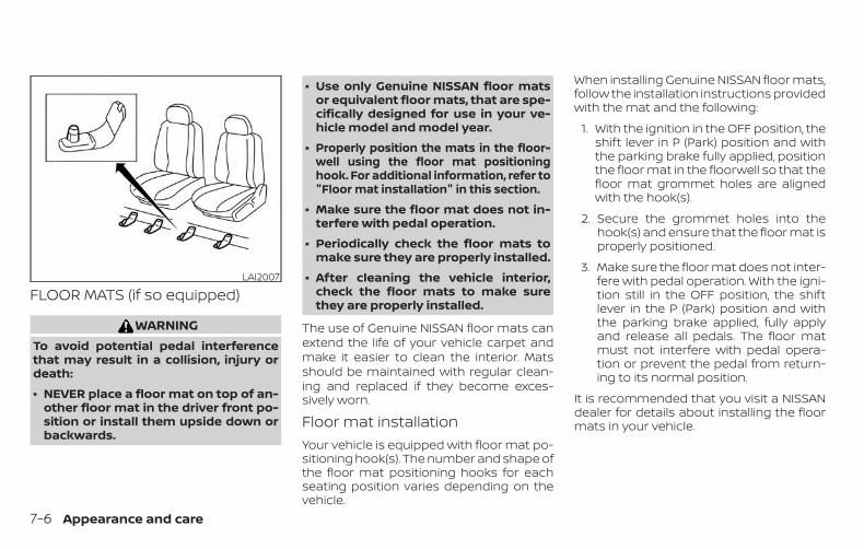
FLOOR MATS (if so equipped)
WARNINGTo avoid potential pedal interferencethat may result in a collision, injury ordeath:
∙ NEVER place a floor mat on top of an-other floor mat in the driver front po-sition or install them upside down orbackwards.
∙ Use only Genuine NISSAN floor matsor equivalent floor mats, that are spe-cifically designed for use in your ve-hicle model and model year.
∙ Properly position the mats in the floor-well using the floor mat positioninghook. For additional information, refer to"Floor mat installation" in this section.
∙ Make sure the floor mat does not in-terfere with pedal operation.
∙ Periodically check the floor mats tomake sure they are properly installed.
∙ After cleaning the vehicle interior,check the floor mats to make surethey are properly installed.
The use of Genuine NISSAN floor mats canextend the life of your vehicle carpet andmake it easier to clean the interior. Matsshould be maintained with regular clean-ing and replaced if they become exces-sively worn.
Floor mat installationYour vehicle is equipped with floor mat po-sitioning hook(s). The number and shape ofthe floor mat positioning hooks for eachseating position varies depending on thevehicle.
When installing Genuine NISSAN floor mats,follow the installation instructions providedwith the mat and the following:
1. With the ignition in the OFF position, theshift lever in P (Park) position and withthe parking brake fully applied, positionthe floor mat in the floorwell so that thefloor mat grommet holes are alignedwith the hook(s).
2. Secure the grommet holes into thehook(s) and ensure that the floor mat isproperly positioned.
3. Make sure the floor mat does not inter-fere with pedal operation. With the igni-tion still in the OFF position, the shiftlever in the P (Park) position and withthe parking brake applied, fully applyand release all pedals. The floor matmust not interfere with pedal opera-tion or prevent the pedal from return-ing to its normal position.
It is recommended that you visit a NISSANdealer for details about installing the floormats in your vehicle.
LAI2007
7-6 Appearance and care

The illustration shows the location of thefloor mat positioning hooks.
SEAT BELTSThe seat belts can be cleaned by wipingthem with a sponge dampened in a mildsoap solution. Allow the belts to dry com-pletely in the shade before using them. Foradditional information, refer to “Seat beltmaintenance” in the “Safety—Seats, seatbelts and supplemental restraint system”section of this manual.
WARNINGDo not allow wet seat belts to roll up inthe retractor. NEVER use bleach, dye orchemical solvents to clean the seatbelts, since these materials may se-verely weaken the seat belt webbing.
CLEANING THE SEAT TRACKS
CAUTIONPeriodically clean the seat tracks to pre-vent reduction of ability to move theseats.
Clean periodically with a high-poweredvacuum cleaner. Dirt and debris may re-duce the ability to adjust the seat. A wetcleansing agent may be used if necessary.
MOST COMMON FACTORSCONTRIBUTING TO VEHICLECORROSIONMost vehicle corrosion is caused by:
∙ The accumulation of moisture-retaining dirt and debris in body panelsections, cavities, and other areas.
∙ Damage to paint and other protectivecoatings caused by gravel and stonechips or minor traffic collisions.
ENVIRONMENTAL FACTORSINFLUENCE THE RATE OFCORROSIONMoistureAccumulation of sand, dirt and water onthe vehicle body underside can acceleratecorrosion. Wet floor coverings will not drycompletely inside the vehicle and shouldbe removed for drying to avoid floor panelcorrosion.
Positioning hooksLAI2046
CORROSION PROTECTION
Appearance and care 7-7

Relative humidityCorrosion will be accelerated in areas ofhigh relative humidity, especially those ar-eas where the temperatures stay abovefreezing and where atmospheric pollutionexists and road salt is used.
TemperatureHigh temperatures accelerate the rate ofcorrosion to those parts which are not wellventilated.
Air pollutionIndustrial pollution, the presence of salt inthe air in coastal areas, or heavy road saltuse accelerates the corrosion process.Road salt also accelerates the disintegra-tion of paint surfaces.
PROTECT YOUR VEHICLE FROMCORROSION
∙ Wash and wax your vehicle often tokeep the vehicle clean.
∙ Always check for minor damage to thepaint and repair it as soon as possible.
∙ Keep drain holes at the bottom of thedoors open to avoid water accumula-tion.
∙ Check the underbody for accumulationof sand, dirt or salt. If present, wash withwater as soon as possible.
CAUTION∙ NEVER remove dirt, sand or other de-
bris from the passenger compart-ment by washing it out with a hose.Remove dirt with a vacuum cleaner orbroom.
∙ Never allow water or other liquids tocome in contact with electronic com-ponents inside the vehicle as this maydamage them.
Chemicals used for road surface de-icingare extremely corrosive. They acceleratecorrosion and deterioration of underbodycomponents such as the exhaust system,fuel and brake lines, brake cables, floor panand fenders.
In winter, the underbody must becleaned periodically.
For additional protection against rust andcorrosion, which may be required in someareas, it is recommended that you consulta NISSAN dealer.
7-8 Appearance and care

8 Do-it-yourself
Maintenance precautions . . . . . . . . . . . . . . . . . . . . . . . 8-2Engine compartment check locations . . . . . . . . . . . 8-3Engine cooling system . . . . . . . . . . . . . . . . . . . . . . . . . . 8-4
Checking engine coolant level . . . . . . . . . . . . . . . . 8-5Changing engine coolant. . . . . . . . . . . . . . . . . . . . . 8-5
Inverter cooling system . . . . . . . . . . . . . . . . . . . . . . . . . 8-6Checking inverter coolant level . . . . . . . . . . . . . . . 8-7Changing inverter coolant . . . . . . . . . . . . . . . . . . . . 8-7
Engine oil. . . . . . . . . . . . . . . . . . . . . . . . . . . . . . . . . . . . . . . . 8-7Checking engine oil level . . . . . . . . . . . . . . . . . . . . . 8-7Changing engine oil . . . . . . . . . . . . . . . . . . . . . . . . . . 8-8Changing engine oil filter . . . . . . . . . . . . . . . . . . . . 8-10
Continuously Variable Transmission (CVT)fluid . . . . . . . . . . . . . . . . . . . . . . . . . . . . . . . . . . . . . . . . . . . . .8-11Brake fluid . . . . . . . . . . . . . . . . . . . . . . . . . . . . . . . . . . . . . . .8-11Windshield-washer fluid . . . . . . . . . . . . . . . . . . . . . . . . 8-12
Windshield-washer fluid reservoir. . . . . . . . . . . . 8-1212-Volt Battery. . . . . . . . . . . . . . . . . . . . . . . . . . . . . . . . . . 8-13
Jump starting . . . . . . . . . . . . . . . . . . . . . . . . . . . . . . . 8-14Spark plugs . . . . . . . . . . . . . . . . . . . . . . . . . . . . . . . . . . . . 8-14
Replacing spark plugs . . . . . . . . . . . . . . . . . . . . . . . 8-14
Air cleaner. . . . . . . . . . . . . . . . . . . . . . . . . . . . . . . . . . . . . . 8-15In-cabin microfilter . . . . . . . . . . . . . . . . . . . . . . . . . . 8-16
Windshield wiper blades . . . . . . . . . . . . . . . . . . . . . . . . 8-16Cleaning . . . . . . . . . . . . . . . . . . . . . . . . . . . . . . . . . . . . 8-16Replacing . . . . . . . . . . . . . . . . . . . . . . . . . . . . . . . . . . . 8-17
Brakes. . . . . . . . . . . . . . . . . . . . . . . . . . . . . . . . . . . . . . . . . . 8-19Fuses. . . . . . . . . . . . . . . . . . . . . . . . . . . . . . . . . . . . . . . . . . .8-20
Engine compartment . . . . . . . . . . . . . . . . . . . . . . .8-20Passenger compartment. . . . . . . . . . . . . . . . . . . . 8-21
Battery replacement . . . . . . . . . . . . . . . . . . . . . . . . . . . 8-22NISSAN Intelligent Key® . . . . . . . . . . . . . . . . . . . . . . 8-22
Lights . . . . . . . . . . . . . . . . . . . . . . . . . . . . . . . . . . . . . . . . . . 8-23Headlights. . . . . . . . . . . . . . . . . . . . . . . . . . . . . . . . . . . 8-23Fog lights (if so equipped) . . . . . . . . . . . . . . . . . . . 8-24Exterior and interior lights . . . . . . . . . . . . . . . . . . . 8-25
Wheels and tires. . . . . . . . . . . . . . . . . . . . . . . . . . . . . . . .8-28Tire pressure . . . . . . . . . . . . . . . . . . . . . . . . . . . . . . . .8-28Tire labeling . . . . . . . . . . . . . . . . . . . . . . . . . . . . . . . . . 8-31Types of tires . . . . . . . . . . . . . . . . . . . . . . . . . . . . . . . . 8-34Tire chains . . . . . . . . . . . . . . . . . . . . . . . . . . . . . . . . . . 8-35Changing wheels and tires . . . . . . . . . . . . . . . . . . 8-36

When performing any inspection or main-tenance work on your vehicle, always takecare to prevent serious accidental injury toyourself or damage to the vehicle. The fol-lowing are general precautions whichshould be closely observed.
WARNING∙ Park the vehicle on a level surface, ap-
ply the parking brake securely andblock the wheels to prevent the ve-hicle from moving. Move the shift le-ver to P (Park).
∙ Be sure the ignition switch is in theOFF or LOCK position when perform-ing any parts replacement or repairs.
∙ If you must work with the engine run-ning, keep your hands, clothing, hairand tools away from moving fans,belts and any other moving parts.
∙ It is advisable to secure or remove anyloose clothing and remove any jew-elry, such as rings, watches, etc. be-fore working on your vehicle.
∙ Always wear eye protection wheneveryou work on your vehicle.
∙ Your vehicle is equipped with an auto-matic engine cooling fan. It may comeon at any time without warning, evenif the ignition switch is in the OFF po-sition and the engine is not running.To avoid injury, always disconnect thenegative battery cable before work-ing near the fan.
∙ If you must run the engine in an en-closed space such as a garage, be surethere is proper ventilation for exhaustgases to escape.
∙ Never get under the vehicle while it issupported only by a jack. If it is neces-sary to work under the vehicle, sup-port it with safety stands.
∙ Keep smoking materials, flame andsparks away from the fuel tank andbattery.
∙ Because the fuel lines on gasoline en-gine models are under high pressureeven when the engine is off, it is recom-mended that you visit a NISSAN dealerfor service of the fuel filter or fuel lines.
CAUTION∙ Do not work under the hood while the
engine is hot. Turn the engine off andwait until it cools down.
∙ Avoid contact with used engine oil andcoolant. Improperly disposed engineoil, engine coolant and/or other vehiclefluids can damage the environment. Al-ways conform to local regulations fordisposal of vehicle fluid.
∙ Never leave the engine or Continu-ously Variable Transmission (CVT) re-lated component harnesses discon-nected while the ignition switch is inthe ON position.
∙ Never connect or disconnect the batteryor any transistorized component whilethe ignition switch is in the ON position.
This “Do-it-yourself ” section gives instruc-tions regarding only those items which arerelatively easy for an owner to perform.
A Genuine NISSAN service manual is alsoavailable. For additional information, referto “Owner’s Manual/Service Manual orderinformation” in the “Technical and con-sumer information” section of this manual.
You should be aware that incomplete orimproper servicing may result in operatingdifficulties or excessive emissions, andcould affect warranty coverage. If in doubtabout any servicing, it is recommendedthat you have it done by a NISSAN dealer.
MAINTENANCE PRECAUTIONS
8-2 Do-it-yourself
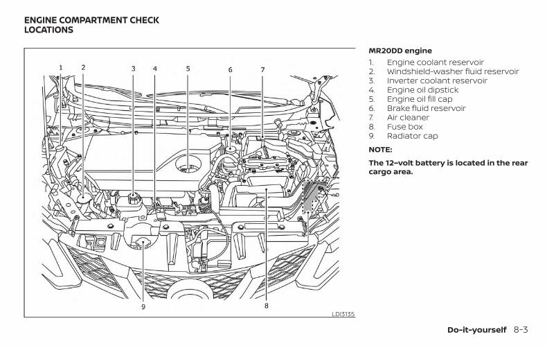
MR20DD engine1. Engine coolant reservoir2. Windshield-washer fluid reservoir3. Inverter coolant reservoir4. Engine oil dipstick5. Engine oil fill cap6. Brake fluid reservoir7. Air cleaner8. Fuse box9. Radiator cap
NOTE:
The 12–volt battery is located in the rearcargo area.
LDI3135
ENGINE COMPARTMENT CHECKLOCATIONS
Do-it-yourself 8-3

The engine cooling system is filled at thefactory with a pre-diluted mixture of 50%Genuine NISSAN Long LifeAntifreeze/Coolant (blue) and 50% water toprovide year-round antifreeze and coolantprotection. The antifreeze solution con-tains rust and corrosion inhibitors. Addi-tional engine cooling system additives arenot necessary.
WARNING∙ Never remove the radiator or coolant
reservoir cap when the engine is hot.Wait until the engine and radiator cooldown. Serious burns could be causedby high pressure fluid escaping fromthe radiator. For additional informa-tion on precautions, refer to “If yourvehicle overheats” in the “In case ofemergency” section of this manual.
∙ The radiator is equipped with a pres-sure type radiator cap. To prevent en-gine damage, use only a GenuineNISSAN radiator cap.
CAUTION∙ Never use any additives in the coolant
such as radiator sealer in the coolingsystem. This may cause damage toelectrical equipment such as the mo-tor and inverter, and also to engineand transmission.
∙ When adding or replacing coolant, besure to use only Genuine NISSAN LongLife Antifreeze/Coolant (blue) orequivalent. Genuine NISSAN Long LifeAntifreeze/Coolant (blue) is pre-diluted to provide antifreeze protec-tion to -34° F (-37° C). If additionalfreeze protection is needed due toweather where you operate your ve-hicle, add Genuine NISSAN Long LifeAntifreeze/Coolant (blue) concen-trate following the directions on thecontainer. If an equivalent coolantother than Genuine NISSAN Long LifeAntifreeze/Coolant (blue) is used, fol-low the coolant manufacturer’s in-structions to maintain minimum anti-freeze protection to -34° F (-37° C). The
use of other types of coolant solu-tions other than Genuine NISSAN LongLife Antifreeze/Coolant (blue) orequivalent may damage the enginecooling system.
∙ The life expectancy of the factory-fillcoolant is 105,000 miles (168,000 km)or 7 years. Mixing any other type ofcoolant other than Genuine NISSANLong Life Antifreeze/Coolant (blue),including Genuine NISSAN Long LifeAntifreeze/Coolant (green), or the useof non-distilled water will reduce thelife expectancy of the factory-fill cool-ant. For additional information, referto the "Maintenance and schedules"section of this manual.
ENGINE COOLING SYSTEM
8-4 Do-it-yourself
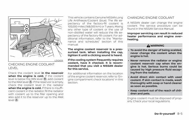
CHECKING ENGINE COOLANTLEVELCheck the coolant level in the reservoirwhen the engine is cold. If the coolantlevel is below the MIN level �B , add coolantto the MAX level �A . If the reservoir is empty,check the coolant level in the radiatorwhen the engine is cold. If there is insuffi-cient coolant in the radiator, fill the radiatorwith coolant up to the filler opening andalso add it to the reservoir up to the MAXlevel �A .
This vehicle contains Genuine NISSAN LongLife Antifreeze/Coolant (blue). The life ex-pectancy of the factory-fill coolant is105,000 miles (168,000 km) or 7 years. Mixingany other type of coolant or the use ofnon-distilled water will reduce the life ex-pectancy of the factory-fill coolant. For ad-ditional information, refer to the "Mainte-nance and schedules" section of thismanual.
The engine coolant reservoir is a pres-surized tank. When installing the cap,tighten it until a clicking sound is heard.
If the cooling system frequently requirescoolant, have it checked. It is recom-mended that you visit a NISSAN dealerfor this service.
For additional information on the locationof the engine coolant reservoir, refer to “En-gine compartment check locations” in thissection.
CHANGING ENGINE COOLANTA NISSAN dealer can change the enginecoolant. The service procedure can befound in the NISSAN Service Manual.
Improper servicing can result in reducedheater performance and engine over-heating.
WARNING∙ To avoid the danger of being scalded,
never change the coolant when theengine is hot.
∙ Never remove the radiator or enginecoolant reservoir cap when the en-gine is hot. Serious burns could becaused by high pressure fluid escap-ing from the radiator.
∙ Avoid direct skin contact with usedcoolant. If skin contact is made, washthoroughly with soap or hand cleaneras soon as possible.
∙ Keep coolant out of the reach of chil-dren and pets.
Engine coolant must be disposed of prop-erly. Check your local regulations.
LDI2659
Do-it-yourself 8-5

The inverter cooling system is filled at thefactory with a pre-diluted mixture of 50%Genuine NISSAN Long LifeAntifreeze/Coolant (blue) and 50% water toprovide year-round antifreeze and coolantprotection. The antifreeze solution con-tains rust and corrosion inhibitors. Addi-tional inverter cooling system additives arenot necessary.
WARNING∙ Never remove the coolant reservoir
cap when the engine and inverter arehot. Wait until the engine and invertercool down. Serious burns could becaused by high pressure fluid escap-ing from the reservoir.
∙ The inverter reservoir is equippedwith a pressure type cap. To preventengine and inverter damage, use onlya Genuine NISSAN inverter reservoircap.
CAUTION∙ Never use any additives in the coolant
such as radiator sealer in the coolingsystem. This may cause damage toelectrical equipment such as the mo-tor and inverter, as well as the engineand transmission.
∙ When adding or replacing coolant, besure to use only a Genuine NISSANLong Life Antifreeze/Coolant (blue) orequivalent. Genuine NISSAN Long LifeAntifreeze/Coolant (blue) is pre-diluted to provide antifreeze protec-tion to -34° F (-37° C). If additional an-tifreeze protection is needed due toweather where you operate your ve-hicle, add Genuine NISSAN Long LifeAntifreeze/Coolant (blue). The use ofother types of coolant solutions otherthan Genuine NISSAN Long LifeAntifreeze/Coolant (blue) or equiva-lent, may damage the inverter coolingsystem.
∙ The life expectancy of the factory-fillcoolant is 125,000 miles (200,000 km)or 15 years. Mixing any other type ofcoolant other than Genuine NISSANLong Life Antifreeze/Coolant (blue),including Genuine NISSAN Long LifeAntifreeze/Coolant (green), or the useon non-distilled water will reduce thelife expectancy of factory-fill coolant.For additional information, refer tothe "Maintenance and schedules"section of this manual.
INVERTER COOLING SYSTEM
8-6 Do-it-yourself

CHECKING INVERTER COOLANTLEVELCheck the coolant level in the reservoirwhen the engine and inverter are cold.The coolant level should be between theMIN level �B , add coolant to the MAX level�A .
If the inverter cooling system frequentlyrequires coolant, have it checked. It isrecommended that you visit a NISSANdealer for this service.
CHANGING INVERTER COOLANTIt is recommended that major cooling sys-tem repairs be done by a NISSAN dealer.The service procedure can be found in theNISSAN Service Manual.
Improper servicing can result in inverteroverheating.
WARNING∙ To avoid the danger of being scalded,
never change the coolant when theinverter is hot.
∙ Never remove the cap when the in-verter is hot. Serious burns could becaused by high pressure fluid escap-ing from the inverter coolantreservoir.
∙ Avoid direct skin contact with usedcoolant. If skin contact is made, washthoroughly with soap or hand cleaneras soon as possible.
∙ Keep coolant out of the reach of chil-dren and pets.
Engine coolant must be disposed of prop-erly. Check your local regulations.
CHECKING ENGINE OIL LEVEL1. Park the vehicle on a level surface and
apply the parking brake.
2. Start the hybrid system and let it idleuntil it reaches operating temperature.
3. Turn off the hybrid system. Wait morethan 10 minutes for the oil to drainback into the oil pan.
4. Remove the dipstick and wipe it clean.Reinsert it all the way.
LDI3078 LDI3053
ENGINE OIL
Do-it-yourself 8-7
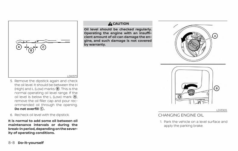
5. Remove the dipstick again and checkthe oil level. It should be between the H(High) and L (Low) marks �B . This is thenormal operating oil level range. If theoil level is below the L (Low) mark �A ,remove the oil filler cap and pour rec-ommended oil through the opening.Do not overfill �C .
6. Recheck oil level with the dipstick.
It is normal to add some oil between oilmaintenance intervals or during thebreak-in period, depending on the sever-ity of operating conditions.
CAUTIONOil level should be checked regularly.Operating the engine with an insuffi-cient amount of oil can damage the en-gine, and such damage is not coveredby warranty.
CHANGING ENGINE OIL1. Park the vehicle on a level surface and
apply the parking brake.
LDI0371
LDI3305
8-8 Do-it-yourself
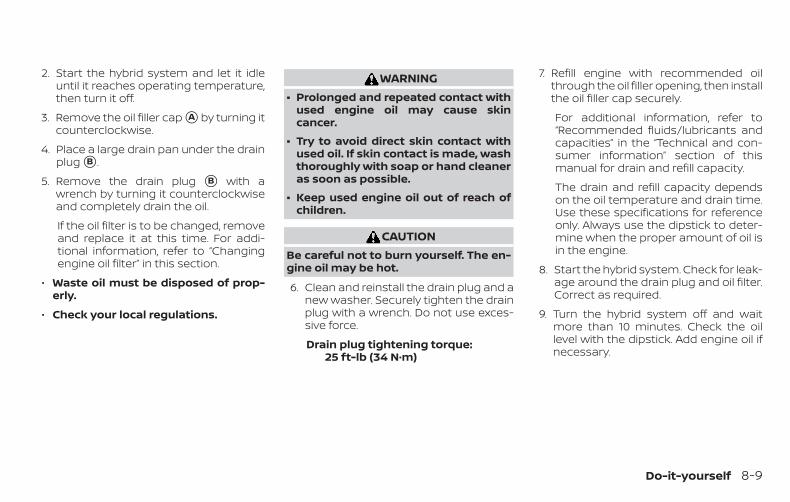
2. Start the hybrid system and let it idleuntil it reaches operating temperature,then turn it off.
3. Remove the oil filler cap �A by turning itcounterclockwise.
4. Place a large drain pan under the drainplug �B .
5. Remove the drain plug �B with awrench by turning it counterclockwiseand completely drain the oil.
If the oil filter is to be changed, removeand replace it at this time. For addi-tional information, refer to “Changingengine oil filter” in this section.
∙ Waste oil must be disposed of prop-erly.
∙ Check your local regulations.
WARNING∙ Prolonged and repeated contact with
used engine oil may cause skincancer.
∙ Try to avoid direct skin contact withused oil. If skin contact is made, washthoroughly with soap or hand cleaneras soon as possible.
∙ Keep used engine oil out of reach ofchildren.
CAUTIONBe careful not to burn yourself. The en-gine oil may be hot.
6. Clean and reinstall the drain plug and anew washer. Securely tighten the drainplug with a wrench. Do not use exces-sive force.
Drain plug tightening torque:25 ft-lb (34 N·m)
7. Refill engine with recommended oilthrough the oil filler opening, then installthe oil filler cap securely.
For additional information, refer to“Recommended fluids/lubricants andcapacities” in the “Technical and con-sumer information” section of thismanual for drain and refill capacity.
The drain and refill capacity dependson the oil temperature and drain time.Use these specifications for referenceonly. Always use the dipstick to deter-mine when the proper amount of oil isin the engine.
8. Start the hybrid system. Check for leak-age around the drain plug and oil filter.Correct as required.
9. Turn the hybrid system off and waitmore than 10 minutes. Check the oillevel with the dipstick. Add engine oil ifnecessary.
Do-it-yourself 8-9

CHANGING ENGINE OIL FILTER1. Park the vehicle on a level surface and
apply the parking brake.
2. Turn the hybrid system off.
3. Place a large drain pan under the oilfilter �B .
4. Remove oil filter �B with an oil filterwrench by turning it counterclockwise.Then remove the oil filter by turning itby hand.
CAUTIONBe careful not to burn yourself. The en-gine oil may be hot.
5. Wipe the engine oil filter sealing surfacewith a clean rag.
CAUTION∙ Be sure to remove any old gasket
material remaining on the sealingsurface of the engine. Failure to doso could lead to an oil leak and en-gine damage.
∙ The dipstick must be inserted inplace to prevent oil spillage fromthe dipstick hole when filling theengine with oil.
6. Coat the gasket on the new filter withclean engine oil.
7. Screw on the oil filter until a slight resis-tance is felt, then tighten an additional2/3 turn.
8. Start the hybrid system and check forleakage around the oil filter. Correct asrequired.
9. Turn the hybrid system off and waitmore than 10 minutes. Check the oillevel. Add engine oil if necessary.
LDI3085
8-10 Do-it-yourself

CAUTION∙ NISSAN recommends using Genuine
NISSAN CVT Fluid NS-3 (or equivalent)ONLY in NISSAN CVTs. Do not mix withother fluids.
∙ Do not use Automatic TransmissionFluid (ATF) or Manual transmissionfluid in a NISSAN CVT, as it may dam-age the CVT. Damage caused by theuse of fluids other than as recom-mended is not covered underNISSAN’s New Vehicle LimitedWarranty.
∙ Using fluids that are not equivalent toGenuine NISSAN CVT Fluid NS-3 mayalso damage the CVT. Damage causedby the use of fluids other than as rec-ommended is not covered underNISSAN’s New Vehicle LimitedWarranty.
When checking or replacement of CVT fluidis required, it is recommended that you visita NISSAN dealer for this service.
WARNING∙ Use only new fluid from a sealed con-
tainer. Old, inferior or contaminatedfluid may damage the brake system.The use of improper fluids can dam-age the brake system and affect thevehicle’s stopping ability.
∙ Clean the filler cap before removing.
∙ Brake fluid is poisonous and shouldbe stored carefully in marked contain-ers out of reach of children.
CAUTIONDo not spill the fluid on any painted sur-faces. This will damage the paint. If fluidis spilled, immediately wash the surfacewith water.
Check the fluid level in the reservoir. If thebrake fluid is below the MIN line �B , thebrake warning light will illuminate. Addbrake fluid up to the MAX line �A . For addi-tional information on brake fluid type, referto “Recommended fluids/lubricants andcapacities” in the “Technical and consumerinformation” section of this manual.
If the brake fluid must be added frequently,the brake system should be thoroughlychecked. It is recommended that you visit aNISSAN dealer for this service.
LDI3079
CONTINUOUSLY VARIABLETRANSMISSION (CVT) FLUID
BRAKE FLUID
Do-it-yourself 8-11

WINDSHIELD-WASHER FLUIDRESERVOIRFill the windshield-washer fluid reservoirperiodically. Add windshield-washer fluidwhen the “Low Washer Fluid” warning mes-sage (if so equipped) shows on the vehicleinformation display or when there is nofluid in the dip tube.
To check the fluid level with the dip tube,use your finger to plug the center hole �A ofthe cap/tube assembly, then remove itfrom the reservoir. If there is no fluid in thedip tube, add fluid.
To fill the windshield-washer fluid reservoir,lift the cap off the reservoir and pour thewindshield-washer fluid into the reservoiropening.
Add a washer solvent to the washer forbetter cleaning. In the winter season, add awindshield washer antifreeze. Follow themanufacturer’s instructions for the mix-ture ratio.
Refill the reservoir more frequently whendriving conditions require an increasedamount of windshield-washer fluid.
Recommended fluid is Genuine NISSANWindshield Washer Concentrate Cleaner &Antifreeze or equivalent.
CAUTION∙ Do not substitute engine antifreeze
coolant for windshield-washer fluid.This may result in damage to thepaint.
∙ Do not fill the windshield-washer fluidreservoir with washer fluid concen-trates at full strength. Some methylalcohol based washer fluid concen-trates may permanently stain thegrille if spilled while filling thewindshield-washer fluid reservoir.
∙ Pre-mix washer fluid concentrateswith water to the manufacturer’s rec-ommended levels before pouring thefluid into the windshield-washer fluidreservoir. Do not use the windshield-washer fluid reservoir to mix thewasher fluid concentrate and water.
LDI3130
WINDSHIELD-WASHER FLUID
8-12 Do-it-yourself

∙ If the battery is labeled “do not open” it ismaintenance free and battery fluidshould not be checked. It is recom-mended that you visit a NISSAN dealeror a qualified specialist workshop toconfirm the battery’s performance.
∙ Keep the battery surface clean and dry.Clean the battery with a solution of bak-ing soda and water.
∙ Make certain the terminal connectionsare clean and securely tightened.
∙ If the vehicle is not to be used for30 days or longer, disconnect the nega-tive (-) battery terminal cable to preventdischarge.
NOTE:
Care should be taken to avoid situationsthat can lead to potential battery dis-charge and potential no-start conditionssuch as:
1. Installation or extended use of elec-tronic accessories that consume bat-tery power when the hybrid system isnot running (Phone chargers, GPS,DVD players, etc.).
2. Vehicle is not driven regularly and/oronly driven short distances.
In these cases, the battery may need tobe charged to maintain battery health.
WARNING∙ Do not expose the battery to flames,
an electrical spark or a cigarette. Hy-drogen gas generated by the batteryis explosive. Explosive gases cancause blindness or injury. Do not allowbattery fluid to contact your skin,eyes, fabrics or painted surfaces. Sul-furic acid can cause blindness or in-jury. After touching a battery or bat-tery cap, do not touch or rub youreyes. Thoroughly wash your hands. Ifthe acid contacts your eyes, skin orclothing, immediately flush with wa-ter for at least 15 minutes and seekmedical attention.
∙ If the 12-volt battery needs to be re-placed, use a battery of the same de-sign. Using the wrong battery cancause hydrogen gas to build up in thevehicle , which could lead to explosionand personal injury.
∙ When working on or near a battery,always wear suitable eye protectionand remove all jewelry.
∙ Battery posts, terminals and relatedaccessories contain lead and leadcompounds. Wash hands afterhandling.
∙ Keep battery out of the reach ofchildren.
12-VOLT BATTERY
Do-it-yourself 8-13
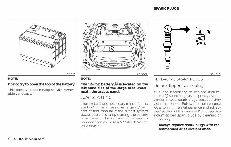
NOTE:
Do not try to open the top of the battery.
This battery is not equipped with remov-able vent caps.
NOTE:
The 12–volt battery�A is located on theleft hand side of the cargo area under-neath the access panel.
JUMP STARTINGIf jump starting is necessary, refer to “Jumpstarting” in the “In case of emergency” sec-tion of this manual. If the hybrid systemdoes not start by jump starting, the batterymay have to be replaced. It is recom-mended that you visit a NISSAN dealer forthis service.
REPLACING SPARK PLUGSIridium-tipped spark plugsIt is not necessary to replace iridium-tipped �A spark plugs as frequently as con-ventional type spark plugs because theylast much longer. Follow the maintenancelog shown in the “Maintenance and sched-ules” section of this manual. Do not serviceiridium-tipped spark plugs by cleaning orregapping.
∙ Always replace spark plugs with rec-ommended or equivalent ones.
LDI2817 LDI3082 SDI1895
SPARK PLUGS
8-14 Do-it-yourself

WARNINGBe sure the engine and ignition switchare off and that the parking brake isengaged securely.
CAUTIONBe sure to use the correct socket to re-move the spark plugs. An incorrectsocket can damage the spark plugs.
If replacement is required, it is recom-mended that you visit a NISSAN dealer forthis service.
The viscous paper type filter elementshould not be cleaned and reused. Replaceit according to the maintenance log shownin the "Maintenance and schedules" sec-tion of this manual.
To remove the air cleaner filter:
1. Pinch retaining clips �2 inward to un-lock, move tab �1 frontward and re-move air duct �B upward.
NOTE:
Do not bend retaining clips outward orthey may break.
2. Unlatch the retaining clips �C andmove air cleaner cover �D forward.
3. Remove air cleaner filter.
Follow the removal instruction in reverseorder to install air cleaner filter, air cleanercover and air cleaner duct.
LDI3192 LDI2819
AIR CLEANER
Do-it-yourself 8-15

NOTE:
After installing a new air cleaner filter,make sure the air cleaner cover and aircleaner duct are seated correctly and allthe retaining clips are latched.
WARNING∙ Operating the engine with the air
cleaner removed can cause you orothers to be burned. The air cleanernot only cleans the air, it stops theflame if the engine backfires. If it isn’tthere, and the engine backfires, youcould be burned. Do not drive with theair cleaner removed, and be carefulwhen working on the engine with theair cleaner removed.
∙ Never pour fuel into the throttle bodyor attempt to start the engine withthe air cleaner removed. Doing socould result in serious injury.
IN-CABIN MICROFILTERThe in-cabin microfilter restricts the entryof airborne dust and pollen particles andreduces some objectionable outsideodors. The filter is located behind the glovebox. For additional information, refer to the“Maintenance and schedules” section ofthis manual for change intervals.
If replacement is required, it is recom-mended that you visit a NISSAN dealer forthis service.
CLEANINGIf your windshield is not clear after usingthe windshield-washer or if a wiper bladechatters when running, wax or other mate-rial may be on the blade or windshield.
Clean the outside of the windshield with awasher solution or a mild detergent. Yourwindshield is clean if beads do not formwhen rinsing with clear water.
Clean each blade by wiping it with a clothsoaked in a washer solution or a mild de-tergent. Then rinse the blades with clearwater. If your windshield is still not clearafter cleaning the blades and using thewiper, replace the blades.
CAUTIONWorn windshield wiper blades candamage the windshield and impairdriver vision.
WINDSHIELD WIPER BLADES
8-16 Do-it-yourself
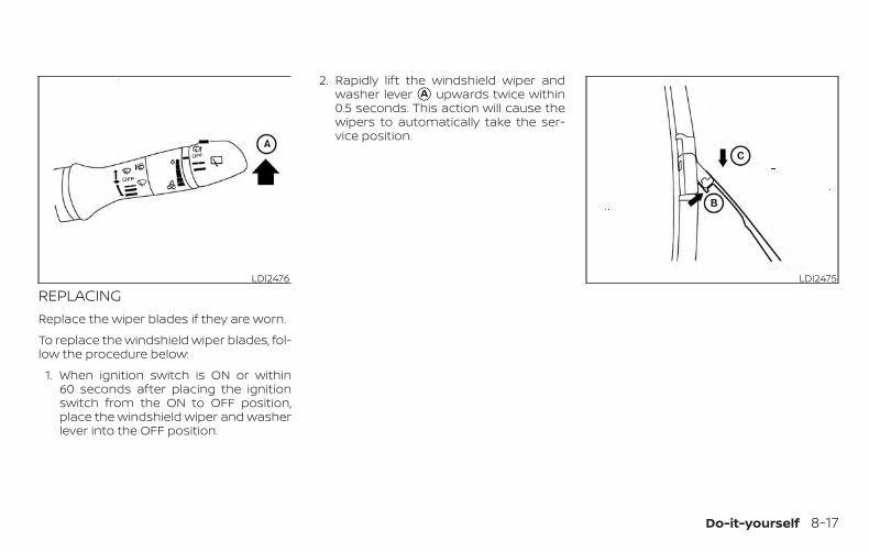
REPLACINGReplace the wiper blades if they are worn.
To replace the windshield wiper blades, fol-low the procedure below:
1. When ignition switch is ON or within60 seconds after placing the ignitionswitch from the ON to OFF position,place the windshield wiper and washerlever into the OFF position.
2. Rapidly lift the windshield wiper andwasher lever �A upwards twice within0.5 seconds. This action will cause thewipers to automatically take the ser-vice position.
LDI2476 LDI2475
Do-it-yourself 8-17
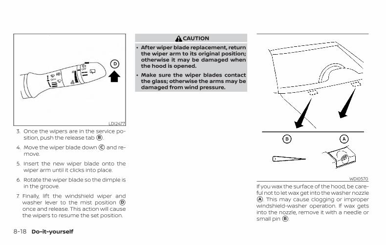
3. Once the wipers are in the service po-sition, push the release tab �B .
4. Move the wiper blade down �C and re-move.
5. Insert the new wiper blade onto thewiper arm until it clicks into place.
6. Rotate the wiper blade so the dimple isin the groove.
7. Finally, lift the windshield wiper andwasher lever to the mist position �Donce and release. This action will causethe wipers to resume the set position.
CAUTION∙ After wiper blade replacement, return
the wiper arm to its original position;otherwise it may be damaged whenthe hood is opened.
∙ Make sure the wiper blades contactthe glass; otherwise the arms may bedamaged from wind pressure.
If you wax the surface of the hood, be care-ful not to let wax get into the washer nozzle�A . This may cause clogging or improperwindshield-washer operation. If wax getsinto the nozzle, remove it with a needle orsmall pin �B .
LDI2477
WDI0570
8-18 Do-it-yourself
Rear window wiper bladeIf checking or replacement is required, it isrecommended that you visit a NISSANdealer for this service.
If the brakes do not operate properly, havethe brakes checked. It is recommendedthat you visit a NISSAN dealer for this ser-vice.
Self-adjusting brakesYour vehicle is equipped with self-adjustingbrakes.
The front and rear disc-type brakes self-adjust every time the brake pedal is ap-plied.
WARNINGHave your brake system checked if thebrake pedal height does not return tonormal. It is recommended that youvisit a NISSAN dealer for this service.
Brake pad wear indicatorsThe disc brake pads on your vehicle haveaudible wear indicators. When a brake padrequires replacement, a high pitchedscraping or screeching sound will be heardwhen the vehicle is in motion. The noise willbe heard whether or not the brake pedal isdepressed. Have the brakes checked assoon as possible if the wear indicatorsound is heard.
Under some driving or climate conditions,occasional brake squeak, squeal or othernoise may be heard. Occasional brakenoise during light to moderate stops is nor-mal and does not affect the function orperformance of the brake system.
Proper brake inspection intervals shouldbe followed. For additional information re-garding brake inspections, refer to the ap-propriate maintenance schedule informa-tion in the "Maintenance and schedules"section of this manual.
BRAKES
Do-it-yourself 8-19

If any electrical equipment does not oper-ate, check for an open fuse.
Fuses are used in the passenger compart-ment and engine compartment. Sparefuses are provided and can be found in thepassenger compartment fuse box.
When installing a fuse make sure the fuse isinstalled in the fuse box securely.
ENGINE COMPARTMENT
WARNINGNever use a fuse of a higher or loweramperage rating than that specified onthe fuse box cover. This could damagethe electrical system or electronic con-trol units or cause a fire
If any electrical equipment does not comeon, check for an open fuse.
For checking and replacing fuses, it is rec-ommended that you visit a NISSAN dealerfor this service.
Fusible linksIf the electrical equipment does not oper-ate and fuses are in good condition, checkthe fusible links. If any of these fusible linksare melted, replace with only GenuineNISSAN parts.
LDI2385 LDI3084
FUSES
8-20 Do-it-yourself
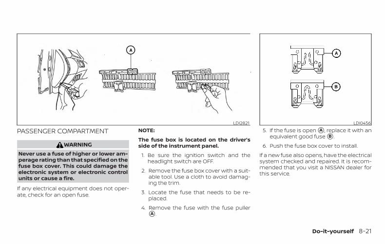
PASSENGER COMPARTMENT
WARNINGNever use a fuse of higher or lower am-perage rating than that specified on thefuse box cover. This could damage theelectronic system or electronic controlunits or cause a fire.
If any electrical equipment does not oper-ate, check for an open fuse.
NOTE:
The fuse box is located on the driver’sside of the instrument panel.
1. Be sure the ignition switch and theheadlight switch are OFF.
2. Remove the fuse box cover with a suit-able tool. Use a cloth to avoid damag-ing the trim.
3. Locate the fuse that needs to be re-placed.
4. Remove the fuse with the fuse puller�A .
5. If the fuse is open �A , replace it with anequivalent good fuse �B .
6. Push the fuse box cover to install.
If a new fuse also opens, have the electricalsystem checked and repaired. It is recom-mended that you visit a NISSAN dealer forthis service.
LDI2821 LDI0456
Do-it-yourself 8-21
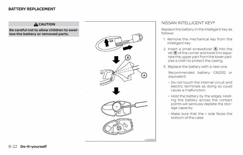
CAUTIONBe careful not to allow children to swal-low the battery or removed parts.
NISSAN INTELLIGENT KEY®Replace the battery in the Intelligent Key asfollows:
1. Remove the mechanical key from theIntelligent Key.
2. Insert a small screwdriver �A into theslit �B of the corner and twist it to sepa-rate the upper part from the lower part.Use a cloth to protect the casing.
3. Replace the battery with a new one.
Recommended battery: CR2032 orequivalent.
∙ Do not touch the internal circuit andelectric terminals as doing so couldcause a malfunction.
∙ Hold the battery by the edges. Hold-ing the battery across the contactpoints will seriously deplete the stor-age capacity.
∙ Make sure that the + side faces thebottom of the case.
LDI2001
BATTERY REPLACEMENT
8-22 Do-it-yourself

4. Close the lid securely as illustrated with�C and �D .
5. Operate the buttons to check the op-eration.
It is recommended that you visit a NISSANdealer for this service if you need assis-tance for replacement.
FCC Notice:
For USA:This device complies with Part 15 of theFCC Rules. Operation is subject to the fol-lowing two conditions: (1) This devicemay not cause harmful interference, and(2) this device must accept any interfer-ence received, including interferencethat may cause undesired operation.
Note: Changes or modifications not ex-pressly approved by the party respon-sible for compliance could void the user’sauthority to operate the equipment.
For Canada:This device complies with IndustryCanada licence-exempt RSS standard(s).Operation is subject to the following twoconditions: (1) this device may not causeinterference, and (2) this device must ac-cept any interference, including interfer-ence that may cause undesired opera-tion of the device.
HEADLIGHTSFor additional information on headlightbulb replacement, refer to the instructionsoutlined in this section.
Replacing the halogen headlightbulb (if so equipped)The headlight is a semi-sealed beam typewhich uses a replaceable headlight (halo-gen) bulb. They can be replaced from insidethe engine compartment without remov-ing the headlight assembly.
If headlight bulb replacement is required, itis recommended that you visit a NISSANdealer for this service.
WDI0568
LIGHTS
Do-it-yourself 8-23

CAUTION∙ Aiming is not necessary after replac-
ing the bulb. When aiming adjustmentis necessary, it is recommended thatyou visit a NISSAN dealer for thisservice.
∙ Do not leave the headlight assemblyopen without a bulb installed for along period of time. Dust, moisture,smoke, etc. entering the headlightbody may affect bulb performance.Remove the bulb from the headlightassembly just before a replacementbulb is installed.
∙ Only touch the base when handlingthe bulb. Never touch the glass enve-lope. Touching the glass could signifi-cantly affect bulb life and/or head-light performance.
∙ High pressure halogen gas is sealedinside the halogen bulb. The bulb maybreak if the glass envelope isscratched or the bulb is dropped.
∙ Use the same number and wattage asshown in the chart.
Fog may temporarily form inside the lensof the exterior lights in the rain or in a carwash. A temperature difference betweenthe inside and the outside of the lenscauses the fog. This is not a malfunction. Iflarge drops of water collect inside the lens,it is recommended that you visit a NISSANdealer for this service.
Replacing the LED headlight bulb(if so equipped)If LED headlight bulb replacement is re-quired, it is recommended that you visit aNISSAN dealer for this service.
FOG LIGHTS (if so equipped)For additional information on fog light bulbreplacement, refer to the instructions out-lined in this section.
Replacing the fog light bulbIf replacement is required, it is recom-mended that you visit a NISSAN dealer forthis service.
CAUTION∙ High pressure halogen gas is sealed
inside the halogen bulb. The bulb maybreak if the glass envelope isscratched or the bulb is dropped.
∙ When handling the bulb, do not touchthe glass envelope.
∙ Use the same number and wattage asoriginally installed as shown in thechart.
∙ Do not leave the bulb out of the foglight for a long period of time as dust,moisture and smoke may enter thefog light body and affect the perfor-mance of the fog light.
8-24 Do-it-yourself

EXTERIOR AND INTERIOR LIGHTSItem Wattage (W) Bulb No.
Headlight assembly (Type A) (if so equipped)*High 65 H9Low 55 H11Turn 28/8 7444NASide marker — —Daytime running lights — —
Headlight assembly (Type B) (if so equipped)*High — —Low — —Turn 28/8 7444NASide marker — —Daytime running lights — —
Front fog lights (if so equipped)* 35 H8Door mirror turn signal light — —Map light* — —Vanity mirror light 1.8 —Glove box light* — —Personal lights (if so equipped) 8 —Cargo light* 8 —High-mounted stop light* — —Rear combination light*
Stop 21 7440Tail/ Stop — —Turn 21 WY21WSide marker 5 W5W
Backup (reversing) assembly*Backup 18 921Tail — —
License plate light* 5 W5W
* It is recommended that you visit a NISSAN dealer for replacement.
Always check with the Parts Department at a NISSAN dealer for the latest parts information.
Do-it-yourself 8-25
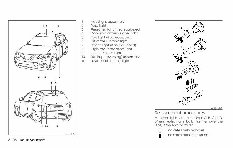
1. Headlight assembly2 Map light3 Personal light (if so equipped)4. Door mirror turn signal light5. Fog light (if so equipped)6. Daytime running light7. Room light (if so equipped)8. High mounted stop light9. License plate light10. Backup (reversing) assembly11. Rear combination light
Replacement proceduresAll other lights are either type A, B, C or D.When replacing a bulb, first remove thelens, lamp and/or cover.
Indicates bulb removalIndicates bulb installationLDI2822
WDI0263
8-26 Do-it-yourself
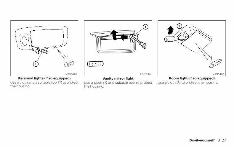
Use a cloth and a suitable tool �1 to protectthe housing.
Use a cloth �1 and suitable tool to protectthe housing.
Use a cloth �1 to protect the housing.Personal lights (if so equipped)
WDI0670Vanity mirror light
LDI2096Room light (if so equipped)
WDI0206
Do-it-yourself 8-27

If you have a flat tire, refer to “Flat tire” inthe “In case of emergency” section ofthis manual.
TIRE PRESSURETire Pressure Monitoring System(TPMS)
WARNINGRadio waves could adversely affectelectric medical equipment. Those whouse a pacemaker should contact theelectric medical equipment manufac-turer for the possible influences beforeuse.
This vehicle is equipped with the Tire Pres-sure Monitoring System (TPMS). It monitorstire pressure of all tires except the spare.When the low tire pressure warning light islit and the “Tire Pressure Low – Add Air”warning appears in the vehicle informationdisplay, one or more of your tires is signifi-cantly under-inflated. If equipped, the sys-tem also displays pressure of all tires (ex-cept the spare tire) on the display screen bysending a signal from a sensor that is in-stalled in each wheel.
The TPMS will activate only when the ve-hicle is driven at speeds above 16 mph
(25 km/h). Also, this system may not detecta sudden drop in tire pressure (for examplea flat tire while driving).
For additional information, refer to “Low tirepressure warning light” in the “Instrumentsand controls” section, “Tire Pressure Moni-toring System (TPMS)” in the “Starting anddriving” section and “Flat tire” in the “In caseof emergency” section of this manual.
Tire inflation pressureCheck the tire pressures (includingthe spare) often and always prior tolong distance trips. The recom-mended tire pressure specificationsare shown on the F.M.V.S.S./C.M.V.S.S.certification label or the Tire andLoading Information label under the“Cold Tire Pressure” heading. The Tireand Loading Information label is af-fixed to the driver side center pillar.Tire pressures should be checkedregularly because:
∙ Most tires naturally lose air overtime.
∙ Tires can lose air suddenly whendriven over potholes or other ob-jects or if the vehicle strikes acurb while parking.
The tire pressures should bechecked when the tires are cold. Thetires are considered COLD after thevehicle has been parked for 3 ormore hours, or driven less than 1 mile(1.6 km) at moderate speeds.The TPMS with Easy-Fill Tire Alertprovides visual and audible signalsoutside the vehicle for inflating thetires to the recommended COLD tirepressure. For additional information,refer to “TPMS with Easy-Fill TireAlert” in the “Starting and driving”section of this manual.
WHEELS AND TIRES
8-28 Do-it-yourself

Incorrect tire pressure, includingunder inflation, may adversely af-fect tire life and vehicle handling.
WARNING∙ Improperly inflated tires can fail
suddenly and cause anaccident.
∙ The Gross Vehicle Weight Rating(GVWR) is located on theF.M.V.S.S./C.M.V.S.S. certifica-tion label. The vehicle weightcapacity is indicated on the Tireand Loading Information label.Do not load your vehicle beyondthis capacity. Overloading yourvehicle may result in reducedtire life, unsafe operating condi-tions due to premature tire fail-ure, or unfavorable handlingcharacteristics and could alsolead to a serious accident. Load-ing beyond the specified capac-ity may also result in failure ofother vehicle components.
∙ Before taking a long trip, orwhenever you heavily load yourvehicle, use a tire pressuregauge to ensure that the tirepressures are at the specifiedlevel.
∙ For additional information re-garding tires, refer to “Impor-tant Tire Safety Information”(US) or “Tire Safety Information”(Canada) in the Warranty Infor-mation Booklet.
Do-it-yourself 8-29

Tire and Loading Informationlabel
�1 Seating capacity: The maximumnumber of occupants that canbe seated in the vehicle.
�2 Tire size - refer to “Tire labeling” inthis section.
�3 Cold tire pressure: Inflate thetires to this pressure when thetires are cold. Tires are consid-ered COLD after the vehicle hasbeen parked for 3 or more hours,or driven less than 1 mile (1.6 km)at moderate speeds. The rec-ommended cold tire inflation isset by the manufacturer to pro-vide the best balance of tirewear, vehicle handling, driveabil-ity, tire noise, etc., up to the vehi-cle’s GVWR.
�4 Original tire size: The size of thetires originally installed on thevehicle at the factory.
�5 Spare tire size.
�6 Vehicle load limit: Refer to “Ve-hicle loading information” in the“Technical and consumer infor-mation” section of this manual.
LDI2737
8-30 Do-it-yourself

Checking tire pressure1. Remove the valve stem cap from
the tire.2. Press the pressure gauge
squarely onto the valve stem. Donot press too hard or force thevalve stem sideways, or air willescape. If the hissing sound of airescaping from the tire is heardwhile checking the pressure, re-position the gauge to eliminatethis leakage.
3. Remove the gauge.
4. Read the tire pressure on thegauge stem and compare to thespecification shown on the Tireand Loading Information label.
5. Add air to the tire as needed. Iftoo much air is added, press thecore of the valve stem brieflywith the tip of the gauge stem torelease pressure. Recheck thepressure and add or release airas needed.
6. Install the valve stem cap.7. Check the pressure of all other
tires, including the spare.
Size Cold Tire Infla-tion Pressure
Front and RearOriginal Tire:225/65R17 102H
41 psi, 280 kPa
Front and RearOriginal Tire:225/60R18 100H
41 psi, 280 kPa
Spare Tire:T155/90D17 101M 60 psi, 420 kPa
TIRE LABELINGFederal law requires tire manufac-turers to place standardized infor-mation on the sidewall of all tires.This information identifies and de-scribes the fundamental character-istics of the tire and also provides theTire Identification Number (TIN) forsafety standard certification. The TINcan be used to identify the tire incase of a recall.
LDI0393Example
WDI0394
Do-it-yourself 8-31

�1 Tire size (example: P215/65R1595H)
1. P: The “P” indicates the tire is de-signed for passenger vehicles(not all tires have this informa-tion).
2. Three-digit number (215): Thisnumber gives the width in milli-meters of the tire from sidewalledge to sidewall edge.
3. Two-digit number (65): Thisnumber, known as the aspectratio, gives the tire’s ratio ofheight to width.
4. R: The “R” stands for radial.5. Two-digit number (15): This num-
ber is the wheel or rim diameterin inches.
6. Two- or three-digit number (95):This number is the tire’s load in-dex. It is a measurement of howmuch weight each tire can sup-port. You may not find this infor-mation on all tires because it isnot required by law.
7. H: Tire speed rating. You shouldnot drive the vehicle faster thanthe tire speed rating.
ExampleWDI0395
8-32 Do-it-yourself

�2 TIN (Tire Identification Number)for a new tire (example: DOT XX XXXXX XXXX)
1. DOT: Abbreviation for the “De-partment Of Transportation”.The symbol can be placedabove, below or to the left orright of the Tire IdentificationNumber.
2. Two-digit code: Manufacturer’sidentification mark.
3. Two-digit code: Tire size.4. Three-digit code: Tire type code
(Optional).5. Four numbers represent the
week and year the tire was built.For example, the numbers 3103means the 31st week of 2003. Ifthese numbers are missing thenlook on the other sidewall of thetire.
�3 Tire ply composition and materialThe number of layers or plies ofrubber-coated fabric in the tire. Tiremanufacturers also must indicatethe materials in the tire, which in-clude steel, nylon, polyester and oth-ers.
�4 Maximum permissible inflationpressureThis number is the greatest amountof air pressure that should be put inthe tire. Do not exceed the maximumpermissible inflation pressure.
�5 Maximum load ratingThis number indicates the maxi-mum load in kilograms and poundsthat can be carried by the tire. Whenreplacing the tires on the vehicle, al-ways use a tire that has the sameload rating as the factory installedtire.
ExampleLDI2786
Do-it-yourself 8-33

�6 Term of “tubeless” or “tube type”
Indicates whether the tire requiresan inner tube (“tube type”) or not(“tubeless”).
�7 The word “radial”The word “radial” is shown if the tirehas radial structure.
�8 Manufacturer or brand nameManufacturer or brand name isshown.Other Tire-related Terminology
In addition to the many terms thatare defined throughout this section,Intended Outboard Sidewall is (1) thesidewall that contains a whitewall,bears white lettering or bearsmanufacturer, brand, and/or modelname molding that is higher ordeeper than the same molding onthe other sidewall of the tire, or (2)the outward facing sidewall of anasymmetrical tire that has a particu-lar side that must always face out-ward when mounted on a vehicle.
TYPES OF TIRES
WARNING∙ When changing or replacing tires, be
sure all four tires are of the same type(i.e., Summer, All Season or Snow) andconstruction. A NISSAN dealer may beable to help you with informationabout tire type, size, speed rating andavailability.
∙ Replacement tires may have a lowerspeed rating than the factoryequipped tires, and may not matchthe potential maximum vehiclespeed. Never exceed the maximumspeed rating of the tire.
∙ Replacing tires with those not origi-nally specified by NISSAN could affectthe proper operation of the low tirepressure warning system.
∙ For additional information regardingtires, refer to “Important Tire SafetyInformation” (US) or “Tire Safety Infor-mation” (Canada) in the Warranty In-formation Booklet.
∙ Always use tires of the same type,size, brand, construction and treadpattern on all four wheels. Failure todo so may result in a circumferencedifference between tires on the frontand rear axles which can cause theVDC system to malfunction resultingin personal injury or death, excessivetire wear and may damage the trans-mission, transfer case and differentialgears.
All-Wheel Drive (AWD) models
CAUTION∙ ONLY use spare tires specified for the
AWD model.
If excessive tire wear is found, it is recom-mended that all four tires be replaced withtires of the same size, brand, constructionand tread pattern. The tire pressure andwheel alignment should also be checkedand corrected as necessary. Contact aNISSAN dealer.
8-34 Do-it-yourself

All season tiresNISSAN specifies All Season tires on somemodels to provide good performance allyear, including snowy and icy road condi-tions. All Season tires are identified by ALLSEASON and/or M&S on the tire sidewall.Snow tires have better snow traction thanAll Season tires and may be more appropri-ate in some areas.
Summer tiresNISSAN specifies summer tires on somemodels to provide superior performanceon dry roads. Summer tire performance issubstantially reduced in snow and ice.Summer tires do not have the tire tractionrating “M&S” on the tire sidewall.
If you plan to operate your vehicle in snowyor icy conditions, NISSAN recommends theuse of SNOW tires or ALL SEASON tires on allfour wheels.
Snow tiresIf snow tires are needed, it is necessary toselect tires equivalent in size and load rat-ing to the original equipment tires. If you donot, it can adversely affect the safety andhandling of your vehicle.
Generally, snow tires have lower speed rat-ings than factory equipped tires and maynot match the potential maximum vehiclespeed. Never exceed the maximum speedrating of the tire.
If you install snow tires, they must be thesame size, brand, construction and treadpattern on all four wheels.
For additional traction on icy roads, stud-ded tires may be used. However, some U.S.states and Canadian provinces prohibittheir use. Check local, state and provinciallaws before installing studded tires. Skidand traction capabilities of studded snowtires on wet or dry surfaces may be poorerthan that of non-studded snow tires.
TIRE CHAINSUse of tire chains may be prohibited ac-cording to location. Check the local lawsbefore installing tire chains. When installingtire chains, make sure they are the propersize for the tires on your vehicle and areinstalled according to the chain manufac-turer’s suggestions. Use only SAE class “S”chains. Class “S” chains are used on ve-hicles with restricted tire to vehicle clear-ance. Vehicles that can use Class “S” chainsare designed to meet the minimum clear-ances between the tire and the closest ve-
hicle suspension or body component re-quired to accommodate the use of awinter traction device (tire chains orcables). The minimum clearances are de-termined using the factory equipped tiresize. Other types may damage your vehicle.Use chain tensioners when recommendedby the tire chain manufacturer to ensure atight fit. Loose end links of the tire chainmust be secured or removed to preventthe possibility of whipping action damageto the fenders or underbody. If possible,avoid fully loading your vehicle when usingtire chains. In addition, drive at a reducedspeed. Otherwise, your vehicle may bedamaged and/or vehicle handling andperformance may be adversely affected.
Do not use tire chains on dry roads. Drivingwith chains in such conditions can causedamage to the various mechanisms of thevehicle due to some overstress.
Do-it-yourself 8-35

CHANGING WHEELS AND TIRESTire rotationNISSAN recommends rotating thetires every 5,000 miles (8,000 km).
For additional information on tire re-placing procedures, refer to “Flat tire”in the “In case of emergency” sectionin this manual.
As soon as possible, tighten thewheel nuts to the specified torquewith a torque wrench.
Wheel nut tightening torque:83 ft-lb (113 N·m)
The wheel nuts must be kept tight-ened to specifications at all times.It is recommended that wheel nutsbe tightened to specification ateach tire rotation interval.
WARNING∙ After rotating the tires, check
and adjust the tire pressure.∙ Retighten the wheel nuts when
the vehicle has been driven for600 miles (1,000 km) (also incases of a flat tire, etc.).
∙ Do not include the spare tire inthe tire rotation.
∙ For additional information re-garding tires, refer to “Impor-tant Tire Safety Information”(US) or “Tire Safety Information”(Canada) in the Warranty Infor-mation Booklet.
Tire wear and damage1. Wear indicator
2. Location mark
WARNING∙ Tires should be periodically in-
spected for wear, cracking,bulging or objects caught in thetread. If excessive wear, cracks,bulging or deep cuts are found,the tire(s) should be replaced.
WDI0258 WDI0259
8-36 Do-it-yourself

∙ The original tires have built-intread wear indicators. When thewear indicators are visible, thetire(s) should be replaced.
∙ Tires degrade with age and use.Have tires, including the spare,over 6 years old checked by aqualified technician becausesome tire damage may not beobvious. Replace the tires asnecessary to prevent tire failureand possible personal injury.
∙ Improper service of the sparetire may result in serious per-sonal injury. If it is necessary torepair the spare tire, it is recom-mended that you visit a NISSANdealer for this service.
∙ For additional information re-garding tires, refer to “Impor-tant Tire Safety Information”(US) or “Tire Safety Information”(Canada) in the Warranty Infor-mation Booklet.
Replacing wheels and tiresWhen replacing a tire, use the same size,tread design, speed rating and load carry-ing capacity as originally equipped. Rec-ommended types and sizes are shown in“Wheels and tires” in the “Technical and con-sumer information” section of this manual.
WARNING∙ The use of tires other than those rec-
ommended or the mixed use of tiresof different brands, construction(bias, bias-belted or radial), or treadpatterns can adversely affect the ride,braking, handling, VDC system,ground clearance, body-to-tire clear-ance, tire chain clearance, speedom-eter calibration, headlight aim andbumper height. Some of these effectsmay lead to accidents and could re-sult in serious personal injury.
∙ For 2WD models, if your vehicle wasoriginally equipped with four tiresthat were the same size and you areonly replacing two of the four tires,install the new tires on the rear axle.Placing new tires on the front axlemay cause loss of vehicle control insome driving conditions and cause anaccident and personal injury
∙ If the wheels are changed for any rea-son, always replace with wheelswhich have the same off-set dimen-sion. Wheels of a different off-setcould cause premature tire wear, de-grade vehicle handling characteris-tics, affect the VDC system and/or in-terference with the brakediscs/drums. Such interference canlead to decreased braking efficiencyand/or early brake pad/shoe wear.For additional information on wheeloff-set dimensions, refer to “Wheelsand tires” in the “Technical and con-sumer information” section of thismanual.
Do-it-yourself 8-37
∙ When replacing a wheel without theTPMS such as the spare tire, the TPMSwill not function and the low tire pres-sure warning light will flash for ap-proximately 1 minute. The light will re-main on after 1 minute. Have yourtires replaced and/or TPMS systemreset as soon as possible. It is recom-mended that you visit a NISSAN dealerfor this service.
∙ Replacing tires with those not origi-nally specified by NISSAN could affectthe proper operation of the TPMS.
∙ The TPMS sensor may be damaged ifit is not handled correctly. Be carefulwhen handling the TPMS sensor.
∙ When replacing the TPMS sensor, theID registration may be required. It isrecommended that you visit a NISSANdealer for ID registration.
∙ Do not use a valve stem cap that is notspecified by NISSAN. The valve stemcap may become stuck.
∙ Be sure that the valve stem caps arecorrectly fitted. Otherwise the valvemay be clogged up with dirt andcause a malfunction or loss ofpressure.
∙ Do not install a damaged or deformedwheel or tire even if it has been re-paired. Such wheels or tires couldhave structural damage and could failwithout warning.
∙ The use of retread tires is notrecommended.
∙ For additional information regardingtires, refer to “Important Tire SafetyInformation” (US) or “Tire Safety Infor-mation” (Canada) in the Warranty In-formation Booklet.
CAUTIONAlways use tires of the same type, size,brand, construction (bias, bias-beltedor radial), and tread pattern on all fourwheels. Failure to do so may result in acircumference difference between tireson the front and rear axles which willcause excessive tire wear and maydamage the transmission, transfer caseand differential gears (AWD models).
If excessive tire wear is found, it is recom-mended that all four tires be replaced withtires of the same size, brand, constructionand tread pattern. The tire pressure andwheel alignment should also be checked
and corrected as necessary. It is recom-mended that you visit a NISSAN dealer forthis service.
Wheel balanceUnbalanced wheels may affect vehiclehandling and tire life. Even with regular use,wheels can get out of balance. Therefore,they should be balanced as required.
Wheel balance service should be per-formed with the wheels off the vehicle.Spin balancing the wheels on the vehiclecould lead to mechanical damage.
∙ For additional information regardingtires, refer to “Important Tire SafetyInformation” (US) or “Tire Safety In-formation” (Canada) in the WarrantyInformation Booklet.
Care of wheels∙ Wash the wheels when washing the ve-
hicle to maintain their appearance.
∙ Clean the inner side of the wheels whenthe wheel is changed or the undersideof the vehicle is washed.
∙ Do not use abrasive cleaners whenwashing the wheels.
8-38 Do-it-yourself

∙ Inspect wheel rims regularly for dentsor corrosion. Such damage may causeloss of pressure or poor seal at the tirebead.
∙ NISSAN recommends waxing the roadwheels to protect against road salt inareas where it is used during winter.
Spare tire (TEMPORARY USE ONLYspare tire)When replacing a wheel without the TPMSsuch as the spare tire, the TPMS will notfunction.
Observe the following precautions if theTEMPORARY USE ONLY spare tire must beused. Otherwise, your vehicle could bedamaged or involved in an accident:
WARNING∙ The spare tire should be used for
emergency use only. It should be re-placed with the standard tire at thefirst opportunity to avoid possible tireor differential damage.
∙ Drive carefully while the TEMPORARYUSE ONLY spare tire is installed. Avoidsharp turns and abrupt braking whiledriving.
∙ Periodically check spare tire inflationpressure. Always keep the pressure ofthe TEMPORARY USE ONLY spare tireat 420 kPa, 4.2 bar (60 psi).
∙ With the TEMPORARY USE ONLY sparetire installed do not drive the vehicleat speeds faster than 50 mph(80 km/h).
∙ When driving on roads covered withsnow or ice, the TEMPORARY USEONLY spare tire should be used on therear wheels and the original tire usedon the front wheels (drive wheels).
∙ Tire tread of the TEMPORARY USEONLY spare tire will wear at a fasterrate than the standard tire. Replacethe spare tire as soon as the treadwear indicators appear.
∙ Do not use the spare tire on othervehicles.
∙ Do not use more than one spare tire atthe same time.
∙ Do not tow a trailer when the TEMPO-RARY USE ONLY spare tire is installed.
CAUTION∙ Do not use tire chains on a TEMPO-
RARY USE ONLY spare tire. Tire chainswill not fit properly and may causedamage to the vehicle.
∙ Because the TEMPORARY USE ONLYspare tire is smaller than the originaltire, ground clearance is reduced. Toavoid damage to the vehicle, do notdrive over obstacles. Also, do not drivethe vehicle through an automatic carwash since it may get caught.
Do-it-yourself 8-39

MEMO
8-40 Do-it-yourself

9 Maintenance and schedules
Maintenance requirements. . . . . . . . . . . . . . . . . . . . . . 9-2General maintenance . . . . . . . . . . . . . . . . . . . . . . . . 9-2Scheduled maintenance . . . . . . . . . . . . . . . . . . . . . 9-2Where to go for service . . . . . . . . . . . . . . . . . . . . . . . 9-2
General maintenance . . . . . . . . . . . . . . . . . . . . . . . . . . . 9-2Explanation of general maintenanceitems. . . . . . . . . . . . . . . . . . . . . . . . . . . . . . . . . . . . . . . . . 9-2
Explanation of scheduled maintenance items . . . 9-5Emission control system maintenance:. . . . . . . 9-5Chassis and body maintenance:. . . . . . . . . . . . . . 9-6
Maintenance schedules . . . . . . . . . . . . . . . . . . . . . . . . . 9-7
Additional maintenance items forsevere operating conditions . . . . . . . . . . . . . . . . . . 9-7
Standard maintenance . . . . . . . . . . . . . . . . . . . . . . . . . . 9-8Emission control system maintenance . . . . . . . 9-8Chassis & body maintenance. . . . . . . . . . . . . . . . 9-10
Maintenance under severe operatingconditions. . . . . . . . . . . . . . . . . . . . . . . . . . . . . . . . . . . . . . 9-12
Severe driving conditions . . . . . . . . . . . . . . . . . . . . 9-12Hybrid Electronic Vehicle (HEV) Li-ion batteryreplacement record . . . . . . . . . . . . . . . . . . . . . . . . . . . . 9-13Maintenance log . . . . . . . . . . . . . . . . . . . . . . . . . . . . . . . 9-15
Some day-to-day and regular mainte-nance is essential to maintain your vehiclegood mechanical condition, as well as itsemissions and engine performance.
It is the owner’s responsibility to make surethat the scheduled maintenance, as well asgeneral maintenance, is performed.
As the vehicle owner, you are the only onewho can ensure that your vehicle receivesproper maintenance. You are a vital link inthe maintenance chain.
GENERAL MAINTENANCEGeneral maintenance includes those itemswhich should be checked during normalday-to-day operation. They are essentialfor proper vehicle operation. It is your re-sponsibility to perform these proceduresregularly as prescribed.
Performing general maintenance checksrequires minimal mechanical skill and onlya few general automotive tools.
These checks or inspections can be doneby yourself, a qualified technician or, if youprefer, a NISSAN dealer.
SCHEDULED MAINTENANCEThe maintenance items listed in this sec-tion are required to be serviced at regularintervals. However under severe drivingconditions, additional or more frequentmaintenance will be required.
WHERE TO GO FOR SERVICEIf maintenance service is required or yourvehicle appears to malfunction, have thesystems checked and serviced. It is recom-mended that you visit a NISSAN dealer forthis service.
NISSAN technicians are well-trained spe-cialists and are kept up-to-date with thelatest service information through techni-cal bulletins, service tips and training pro-grams. They are completely qualified towork on NISSAN vehicles before work be-gins.
You can be confident that a NISSAN deal-er’s service department can perform theservice needed to meet the maintenancerequirements on your vehicle.
During the normal day-to-day operation ofthe vehicle, general maintenance shouldbe performed regularly as prescribed inthis section. If you detect any unusualsounds, vibrations or smells, be sure tocheck for the cause or have it checkedpromptly. In addition, it is recommendedthat you visit a NISSAN dealer if you thinkthat repairs are required.
When performing any checks or mainte-nance work, closely observe the “Mainte-nance precautions” in the “Do-it-yourself ”section of this manual.
EXPLANATION OF GENERALMAINTENANCE ITEMSAdditional information on the followingitems with “ * ” is found in the “Do-it-yourself” section of this manual.
Outside the vehicleThe maintenance items listed here shouldbe performed from time to time, unlessotherwise specified.
MAINTENANCE REQUIREMENTS GENERAL MAINTENANCE
9-2 Maintenance and schedules
Doors and engine hood: Check that thedoors and engine hood operate properly.Also ensure that all latches lock securely.Lubricate hinges, latches, latch pins, rollersand links if necessary. Make sure that thesecondary latch keeps the hood fromopening when the primary latch is re-leased.
When driving in areas using road salt orother corrosive materials, check lubrica-tion frequently.
Lights*: Clean the headlights on a regularbasis. Make sure that the headlights, stoplights, tail lights, turn signal lights, and otherlights are all operating properly and in-stalled securely. Also check headlight aim.
Road wheel nuts (lug nuts)*: When check-ing the tires, make sure no wheel nuts aremissing, and check for any loose wheelnuts. Tighten if necessary.
Tire rotation*: Tires should be rotated ev-ery 5,000 miles (8,000 km).
Tires*: Check the pressure with a gaugeoften and always prior to long distancetrips. If necessary, adjust the pressure in alltires, including the spare, to the pressurespecified. Check carefully for damage, cutsor excessive wear.
Tire Pressure Monitoring System (TPMS)transmitter components: Replace theTPMS transmitter grommet seal, valve coreand cap when the tires are replaced due towear or age.
Wheel alignment and balance: If the ve-hicle should pull to either side while drivingon a straight and level road, or if you detectuneven or abnormal tire wear, there maybe a need for wheel alignment. If the steer-ing wheel or seat vibrates at normal high-way speeds, wheel balancing may beneeded.
For additional information regarding tires,refer to “Important Tire Safety Information”(US) or “Tire Safety Information” (Canada) inthe Warranty Information Booklet.
Windshield: Clean the windshield on aregular basis. Check the windshield at leastevery six months for cracks or other dam-age. Have a damaged windshield repairedby a qualified repair facility.
Windshield wiper blades*: Check forcracks or wear if they do not wipe properly.
Inside the vehicleThe maintenance items listed here shouldbe checked on a regular basis, such as
when performing scheduled maintenance,cleaning the vehicle, etc.
Accelerator pedal: Check the pedal forsmooth operation and make sure thepedal does not catch or require uneveneffort. Keep the floor mat away from thepedal.
Brake pedal: Check the pedal for smoothoperation. If the brake pedal suddenly goesdown further than normal, the pedal feelsspongy or the vehicle seems to take longerto stop, have your vehicle checked imme-diately. It is recommended that you visit aNISSAN dealer for this service. Keep thefloor mat away from the pedal.
Brakes: Check that the brakes do not pullthe vehicle to one side when applied.
Continuously Variable Transmission(CVT) P (Park) position mechanism: On afairly steep hill check that the vehicle is heldsecurely with the shift lever in the P (Park)position without applying any brakes.
Parking brake: Check the parking brakeoperation regularly. The vehicle should besecurely held on a fairly steep hill with onlythe parking brake applied. If the parking
Maintenance and schedules 9-3

brake needs adjustment, it is recom-mended that you visit a NISSAN dealer forthis service.
Seats: Check seat position controls suchas seat adjusters, seatback recliner, etc., toensure they operate smoothly and alllatches lock securely in every position.Check that the head restraints/headrestsmove up and down smoothly and the locks(if so equipped) hold securely in all latchedpositions.
Seat belts: Check that all parts of the seatbelt system (for example, buckles, anchors,adjusters and retractors) operate properlyand smoothly, and are installed securely.Check the belt webbing for cuts, fraying,wear or damage.
Steering wheel: Check for changes in thesteering system, such as excessive freeplay, hard steering or strange noises.
Warning lights and chimes: Make sure allwarning lights and chimes are operatingproperly.
Windshield defroster: Check that the aircomes out of the defroster outlets properlyand in sufficient quantity when operatingthe heater or air conditioner.
Windshield wiper and washer*: Checkthat the wipers and washer operate prop-erly and that the wipers do not streak.
Under the hood and vehicleThe maintenance items listed here shouldbe checked periodically (for example, eachtime you check the engine oil or refuel).
12-Volt battery*: This vehicle is equippedwith a sealed maintenance free battery. It isrecommended that you visit a NISSANdealer for service.
NOTE:
Care should be taken to avoid situationsthat can lead to potential battery dis-charge and potential no-start conditionssuch as:
1. Installation or extended use of elec-tronic accessories that consume bat-tery power when the hybrid system isnot running (Phone chargers, GPS,DVD players, etc.).
2. Vehicle is not driven regularly and/oronly driven short distances.
In these cases, the battery may need tobe charged to maintain battery health.
Brake fluid level*: Make sure that the brakefluid level is between the MAX and MIN lineson the reservoir.
Engine coolant level*: Check the coolantlevel when the engine is cold.
Inverter coolant level*: Check the coolantlevel when the inverter is cold.
Engine oil level*: Check the level afterparking the vehicle on a level spot andturning off the engine. Wait more than15 minutes for the oil to drain back into theoil pan.
Exhaust system: Make sure there are noloose supports, cracks or holes. If thesound of the exhaust seems unusual orthere is a smell of exhaust fumes, immedi-ately have the exhaust system inspected. Itis recommended that you visit a NISSANdealer for this service. For additional infor-mation, refer to “Exhaust gas (carbon mon-oxide)” in the “Starting and driving” sectionof this manual.
9-4 Maintenance and schedules

Fluid leaks: Check under the vehicle forfuel, oil, water or other fluid leaks after thevehicle has been parked for a while. Waterdripping from the air conditioner after useis normal. If you should notice any leaks or iffuel fumes are evident, check for the causeand have it corrected immediately.
Radiator and hoses: Check the front of theradiator and clean off any dirt, insects,leaves, etc., that may have accumulated.Make sure the hoses have no cracks, defor-mation, rot or loose connections.
Underbody: The underbody is frequentlyexposed to corrosive substances such asthose used on icy roads or to control dust. Itis very important to remove these sub-stances, otherwise rust may form on thefloor pan, frame, fuel lines and around theexhaust system. At the end of winter, theunderbody should be thoroughly flushedwith plain water, being careful to cleanthose areas where mud and dirt may accu-mulate. For additional information, refer tothe “Appearance and care” section of thismanual.
Windshield-washer fluid*: Check thatthere is adequate fluid in the reservoir.
The following descriptions are provided togive you a better understanding of thescheduled maintenance items that shouldbe regularly checked or replaced. Themaintenance schedule indicates at whichmileage/time intervals each item requiresservice.
In addition to scheduled maintenance,your vehicle requires that some items bechecked during normal day-to-day opera-tion. For additional information, refer to“General maintenance” in this section.
Items marked with “*” are recommendedby NISSAN for reliable vehicle operation.You are not required to perform mainte-nance on these items in order to maintainthe warranties which come with yourNISSAN. Other maintenance items and in-tervals are required.
When applicable, additional informationcan be found in the “Do-it-yourself ” sectionof this manual.
NOTE:
NISSAN does not advocate the use ofnon-OEM approved aftermarket flush-ing systems and strongly advisesagainst performing these services on aNISSAN product. Many of the aftermar-ket flushing systems use non-OEM ap-proved chemicals or solvents, the use ofwhich has not been validated by NISSAN.
For recommended fuel, lubricants, fluids,grease, and refrigerant, refer to “Recom-mended fluids/lubricants and capaci-ties” in the “Technical and consumer in-formation” section of this manual.
EMISSION CONTROL SYSTEMMAINTENANCE:Engine air filter: Replace at specified inter-vals. When driving for prolonged periods industy conditions, check/replace the filtermore frequently.
EXPLANATION OF SCHEDULEDMAINTENANCE ITEMS
Maintenance and schedules 9-5

Engine coolant*: Replace coolant at thespecified interval. When adding or replac-ing coolant, be sure to use only GenuineNISSAN Long Life Antifreeze/Coolant (blue)or equivalent with the proper mixture. (Foradditional information on the proper mix-ture for your area, refer to “Engine coolingsystem” in the “Do-it-yourself ” section ofthis manual.)
NOTE: Mixing any other type of coolantor the use of non-distilled water may re-duce the recommended service intervalof the coolant.
Hybrid Electronic Vehicle (HEV) invertercoolant: Replace coolant at the specifiedinterval. When adding or replacing coolant,be sure to use only Genuine NISSAN LongLife Antifreeze/Coolant (blue) or equivalentwith the proper mixture. (For additional in-formation on the proper mixture for yourarea, refer to “Engine cooling system” in the“Do-it-yourself ” section of this manual.)
NOTE: Mixing any other type of coolantor the use of non-distilled water may re-duce the recommended service intervalof the coolant.
Engine oil and oil filter: Replace engine oiland oil filter at the specified intervals. Forrecommended oil grade and viscosity refer
to “Recommended fluids/lubricants andcapacities” in the “Technical and consumerinformation” section of this manual.
Engine valve clearance*: Inspect only ifvalve noise increase. Adjust valve clearanceif necessary.
Evaporative emissions control vaporlines*: Check vapor lines for leaks or loose-ness. Tighten connections or replace partsas necessary.
Fuel filter*: Periodic maintenance is not re-quires. (in-tank type filter)
Fuel lines*: Check the fuel hoses, pipingand connections for leaks, looseness, ordeterioration. Tighten connections or re-place parts as necessary.
Spark plugs: Replace at specified intervals.Install new plugs of the same type as origi-nally equipped.
CHASSIS AND BODYMAINTENANCE:Brake lines and cables: Visually inspect forproper installation. Check for chafing,cracks, deterioration, and signs of leaking.Replace any deteriorated or damagedparts immediately.
Brake pads and rotors: Check for wear,deterioration and fluid leaks. Replace anydeteriorated or damaged parts immedi-ately.
Exhaust system: Visually inspect the ex-haust pipes, muffler and hangers for leaks,cracks, deterioration, and damage. Tightenconnections or replace parts as necessary.
In-cabin microfilter: Replace at specifiedintervals. When driving for prolonged peri-ods in dusty conditions, replace the filtermore frequently.
Propeller shaft(s): Check for damage,looseness, and grease leakage. (AWD)
Steering gear and linkage, axle and sus-pension parts, drive shaft boots: Checkfor damage, looseness, and leakage of oilor grease. Under severe driving conditions,inspect more frequently.
Tire rotation: Tires should be rotated every5,000 miles (8,000 km) according to the in-structions under “Explanation of generalmaintenance items” in this section. Whenrotating tires, check for damage and un-even wear. Replace if necessary.
Transmission fluid/oil, differential oil,transfer case oil: Visually inspect for signsof leakage at specified intervals.
9-6 Maintenance and schedules

If using a car-top carrier or driving on roughor muddy roads:
∙ Replace the fluid/oil every 20,000 miles(32,000 km) or 24 months.
∙ Replace the CVT fluid every 30,000 miles(48,000 km).
Off-road maintenance: Check the follow-ing items frequently whenever you driveoff-road through deep sand, mud or water:
∙ Brake pads and rotors
∙ Brake lines and hoses
∙ Differential, transmission and transfercase oil
∙ Steering linkage
∙ Propeller shaft(s) and front drive shafts
∙ Engine air filter
To help ensure smooth, safe and economi-cal driving, NISSAN provides two mainte-nance schedules that may be used, de-pending upon the conditions in which youusually drive. These schedules containboth distance and time intervals, up to120,000 miles (192,000 km)/144 months. Formost people, the odometer reading will in-dicate when service is needed. However, ifyou drive very little, your vehicle should beserviced at the regular time intervalsshown in the schedule.
After 120,000 miles (192,000 km)/144 months, continue maintenance atthe same mileage/time intervals.
ADDITIONAL MAINTENANCE ITEMSFOR SEVERE OPERATINGCONDITIONSAdditional maintenance items for severeoperating conditions should be per-formed on vehicles that are driven underespecially demanding conditions. Addi-tional maintenance items should be per-formed if you primarily operate your vehicleunder the following conditions:
∙ Repeated short trips of less than 5 miles(8 km).
∙ Repeated short trips of less than10 miles (16 km) with outside tempera-tures remaining below freezing.
∙ Operating in hot weather in stop-an-go“rush hour” traffic.
∙ Extensive idling and/or low speed driv-ing for long distances, such as police,taxi or door-to-door delivery use.
∙ Driving in dusty conditions.
∙ Driving on rough, muddy or salt spreadroads.
∙ Using a car-top carrier.
NOTE:
For vehicles operated in Canada, bothstandard and severe maintenance itemsshould be performed at every interval.
MAINTENANCE SCHEDULES
Maintenance and schedules 9-7

The following tables show the standardmaintenance schedule. Depending uponweather and atmospheric conditions,varying road surfaces, individual drivinghabits and vehicle usage, additional ormore frequent maintenance may be re-quired. After 120,000 miles(192,000 km)/144 months, continuemaintenance at the same mileage/timeinterval.EMISSION CONTROL SYSTEM MAINTENANCE
Abbreviations: I = Inspect and correct or replace as necessary, R = Replace
MAINTENANCE OPERATIONPerform at number of miles, kilometers or
months, whichever comes first.miles x 1,000(km x 1,000)
Months
MAINTENANCE INTERVAL5
(8)6
10(16)12
15(24)18
20(32)24
25(40)30
30(48)36
35(56)42
40(64)48
45(72)54
50(80)60
55(88)66
60(96)72
Air cleaner filter See NOTE (1) R REVAP vapor lines I* I* I*Fuel lines I* I* I*Fuel filter See NOTE (2)Engine coolant* See NOTE (3)(4)Inverter coolant See NOTE (4)(5)Engine oil R R R R R R R R R R R REngine oil filter R R R R R R R R R R R RSpark plugs See NOTE (6) Replace every 105,000 miles (168,000 km)Intake and exhaust valve clearances* See NOTE (7)
STANDARD MAINTENANCE
9-8 Maintenance and schedules
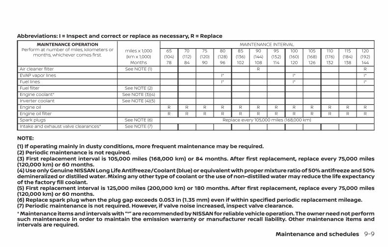
Abbreviations: I = Inspect and correct or replace as necessary, R = ReplaceMAINTENANCE OPERATION
Perform at number of miles, kilometers ormonths, whichever comes first.
miles x 1,000(km x 1,000)
Months
MAINTENANCE INTERVAL65
(104)78
70(112)84
75(120)90
80(128)96
85(136)102
90(144)108
95(152)114
100(160)120
105(168)126
110(176)132
115(184)138
120(192)144
Air cleaner filter See NOTE (1) R REVAP vapor lines I* I* I*Fuel lines I* I* I*Fuel filter See NOTE (2)Engine coolant* See NOTE (3)(4)Inverter coolant See NOTE (4)(5)Engine oil R R R R R R R R R R R REngine oil filter R R R R R R R R R R R RSpark plugs See NOTE (6) Replace every 105,000 miles (168,000 km)Intake and exhaust valve clearances* See NOTE (7)
NOTE:(1) If operating mainly in dusty conditions, more frequent maintenance may be required.(2) Periodic maintenance is not required.(3) First replacement interval is 105,000 miles (168,000 km) or 84 months. After first replacement, replace every 75,000 miles(120,000 km) or 60 months.(4) Use only Genuine NISSAN Long Life Antifreeze/Coolant (blue) or equivalent with proper mixture ratio of 50% antifreeze and 50%demineralized or distilled water. Mixing any other type of coolant or the use of non-distilled water may reduce the life expectancyof the factory fill coolant.(5) First replacement interval is 125,000 miles (200,000 km) or 180 months. After first replacement, replace every 75,000 miles(120,000 km) or 60 months.(6) Replace spark plug when the plug gap exceeds 0.053 in (1.35 mm) even if within specified periodic replacement mileage.(7) Periodic maintenance is not required. However, if valve noise increased, inspect valve clearance.* Maintenance items and intervals with “*” are recommended by NISSAN for reliable vehicle operation. The owner need not performsuch maintenance in order to maintain the emission warranty or manufacturer recall liability. Other maintenance items andintervals are required.
Maintenance and schedules 9-9

CHASSIS & BODY MAINTENANCE
Abbreviations: I = Inspect and correct or replace as necessary, R = Replace, [ ] = At specified mileage only.
MAINTENANCE OPERATIONPerform at number of miles, kilometers or months, which-
ever comes first.miles x 1,000(km x 1,000)
Months
MAINTENANCE INTERVAL5
(8)6
10(16)12
15(24)18
20(32)24
25(40)30
30(48)36
35(56)42
40(64)48
45(72)54
50(80)60
55(88)66
60(96)72
Brake lines & cables I I I I I IBrake pads & rotors� I I I I I IBrake fluid� R R RCVT fluid See NOTE (1) [R] [R]CVT fluid (for leaks) I I I I I ITransfer fluid & differential gear oil See NOTE (2) I I I I I ISteering gear and linkage, axle and suspension parts� I I ITire rotation See NOTE (3)Propeller shaft & drive shaft boots (AWD models)� I I I I I IExhaust system� I I IIn-cabin microfilter R R R RNISSAN Intelligent Key® battery I R R R
9-10 Maintenance and schedules

Abbreviations: I = Inspect and correct or replace as necessary, R = Replace, [ ] = At specified mileage only.
MAINTENANCE OPERATIONPerform at number of miles, kilometers or
months, whichever comes first.miles x 1,000(km x 1,000)
Months
MAINTENANCE INTERVAL65
(104)78
70(112)84
75(120)90
80(128)96
85(136)102
90(144)108
95(152)114
100(160)120
105(168)126
110(176)132
115(184)138
120(192)144
Brake lines and cables I I I I I IBrake pads and rotors� I I I I I IBrake fluid� R R RCVT fluid See NOTE (1) [R] [R]CVT fluid (for leaks) I I I I I ITransfer fluid & differential gear oil See NOTE (2) I I I I I ISteering gear and linkage, axle and suspensionparts�
I I I
Tire rotation See NOTE (3)Propeller shaft & drive shaft boots (AWD mod-els)�
I I I I I I
Exhaust system� I I IIn-cabin microfilter R R R RNISSAN Intelligent Key® battery R R R R
NOTE:
Maintenance items with “�” should be performed more frequently according to “Maintenance under severe driving conditions”.(1) If repeatedly driving short distances, driving in mountainous areas, diving in hill area or low speed driving (average speed< 19 mph (30 km/h)), replace the CVT fluid every 15,000 miles (24,000 km).(2) If using a car-top carrier or driving on rough or muddy roads, change (not just inspect) oil at every 20,000 miles (32,000 km) or24 months.(3) For additional information on tire rotation, refer to “General maintenance” in this section.
Maintenance and schedules 9-11

The maintenance intervals shown on thepreceding pages are for normal operatingconditions. If the vehicle is mainly operatedunder severe driving conditions as shownbelow, more frequent maintenance mustbe performed on the following items asshown in the table.
SEVERE DRIVING CONDITIONS∙ Repeated short trips of less than 5 miles
(8 km).
∙ Repeated short trips of less than10 miles (16 km) with outside tempera-tures remaining below freezing.
∙ Operating in hot weather in stop-and-go “rush hour” traffic.
∙ Extensive idling and/or low speed driv-ing for long distance, such as police, taxior door-to-door delivery use.
∙ Driving in dusty conditions.
∙ Driving on rough, muddy or salt spreadroads.
∙ Using a car-top carrier.
Maintenance operation: Inspect = Inspect and correct or replace as necessary.
Maintenance item Maintenance operation Maintenance intervalBrake fluid Replace Every 10,000 miles (16,000 km) or 12 monthsBrake pads & rotors Inspect Every 5,000 miles (8,000 km) or 6 monthsSteering gear & linkage, axle & suspension parts Inspect Every 5,000 miles (8,000 km) or 6 monthsPropeller shaft & drive shaft boots (AWD models) Inspect Every 5,000 miles (8,000 km) or 6 monthsExhaust system Inspect Every 5,000 miles (8,000 km) or 6 months
MAINTENANCE UNDER SEVEREOPERATING CONDITIONS
9-12 Maintenance and schedules

When replacing the Li-ion battery pack, besure to record the serial No. in the spaceprovided.
HYBRID ELECTRONIC VEHICLE (HEV)LI-ION BATTERY REPLACEMENTRECORD
Maintenance and schedules 9-13
LTI2263
9-14 Maintenance and schedules

5,000 Miles (8,000 km) or 6MonthsDealer Name:Date:Mileage:DealerStamp:
10,000 Miles (16,000 km) or 12MonthsDealer Name:Date:Mileage:DealerStamp:
15,000 Miles (24,000 km) or 18MonthsDealer Name:Date:Mileage:DealerStamp:
20,000 Miles (32,000 km) or 24MonthsDealer Name:Date:Mileage:DealerStamp:
25,000 Miles (40,000 km) or 30MonthsDealer Name:Date:Mileage:DealerStamp:
30,000 Miles (48,000 km) or 36MonthsDealer Name:Date:Mileage:DealerStamp:
35,000 Miles (56,000 km) or 42MonthsDealer Name:Date:Mileage:DealerStamp:
40,000 Miles (64,000 km) or 48MonthsDealer Name:Date:Mileage:DealerStamp:
45,000 Miles (72,000 km) or 54MonthsDealer Name:Date:Mileage:DealerStamp:
MAINTENANCE LOG
Maintenance and schedules 9-15
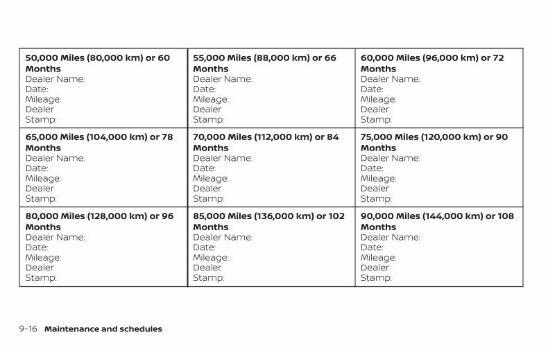
50,000 Miles (80,000 km) or 60MonthsDealer Name:Date:Mileage:DealerStamp:
55,000 Miles (88,000 km) or 66MonthsDealer Name:Date:Mileage:DealerStamp:
60,000 Miles (96,000 km) or 72MonthsDealer Name:Date:Mileage:DealerStamp:
65,000 Miles (104,000 km) or 78MonthsDealer Name:Date:Mileage:DealerStamp:
70,000 Miles (112,000 km) or 84MonthsDealer Name:Date:Mileage:DealerStamp:
75,000 Miles (120,000 km) or 90MonthsDealer Name:Date:Mileage:DealerStamp:
80,000 Miles (128,000 km) or 96MonthsDealer Name:Date:Mileage:DealerStamp:
85,000 Miles (136,000 km) or 102MonthsDealer Name:Date:Mileage:DealerStamp:
90,000 Miles (144,000 km) or 108MonthsDealer Name:Date:Mileage:DealerStamp:
9-16 Maintenance and schedules

95,000 Miles (152,000 km) or 114MonthsDealer Name:Date:Mileage:DealerStamp:
100,000 Miles (160,000 km) or120 MonthsDealer Name:Date:Mileage:DealerStamp:
105,000 Miles (168,000 km) or 126MonthsDealer Name:Date:Mileage:DealerStamp:
110,000 Miles (176,000 km) or 132MonthsDealer Name:Date:Mileage:DealerStamp:
115,000 Miles (184,000 km) or 138MonthsDealer Name:Date:Mileage:DealerStamp:
120,000 Miles (192,000 km) or 144MonthsDealer Name:Date:Mileage:DealerStamp:
Maintenance and schedules 9-17

MEMO
9-18 Maintenance and schedules

10 Technical and consumer information
Recommended fluids/lubricants andcapacities . . . . . . . . . . . . . . . . . . . . . . . . . . . . . . . . . . . . . . 10-2
Fuel recommendation. . . . . . . . . . . . . . . . . . . . . . . 10-4Engine oil and oil filterrecommendations . . . . . . . . . . . . . . . . . . . . . . . . . . 10-7Air conditioner system refrigerant andoil recommendations . . . . . . . . . . . . . . . . . . . . . . . 10-8
Specifications . . . . . . . . . . . . . . . . . . . . . . . . . . . . . . . . . . 10-9Engine . . . . . . . . . . . . . . . . . . . . . . . . . . . . . . . . . . . . . . 10-9Wheels and tires. . . . . . . . . . . . . . . . . . . . . . . . . . . . 10-10Dimensions and weights . . . . . . . . . . . . . . . . . . . 10-10
When traveling or registering in anothercountry. . . . . . . . . . . . . . . . . . . . . . . . . . . . . . . . . . . . . . . . . 10-11Vehicle identification . . . . . . . . . . . . . . . . . . . . . . . . . . . 10-11
Vehicle Identification Number (VIN)plate . . . . . . . . . . . . . . . . . . . . . . . . . . . . . . . . . . . . . . . . 10-11Vehicle identification number(chassis number) . . . . . . . . . . . . . . . . . . . . . . . . . . . . 10-11Engine serial number. . . . . . . . . . . . . . . . . . . . . . . 10-12F.M.V.S.S./C.M.V.S.S. certification label . . . . . . . . 10-12Emission control information label . . . . . . . . . 10-12Tire and Loading Information label . . . . . . . . . 10-13
Air conditioner specification label. . . . . . . . . . . 10-13Installing front license plate. . . . . . . . . . . . . . . . . . . . 10-13Vehicle loading information . . . . . . . . . . . . . . . . . . . 10-14
Terms . . . . . . . . . . . . . . . . . . . . . . . . . . . . . . . . . . . . . . 10-14Vehicle load capacity . . . . . . . . . . . . . . . . . . . . . . . 10-15Securing the load. . . . . . . . . . . . . . . . . . . . . . . . . . . 10-16Loading tips . . . . . . . . . . . . . . . . . . . . . . . . . . . . . . . . 10-17Measurement of weights . . . . . . . . . . . . . . . . . . . 10-17
Towing a trailer . . . . . . . . . . . . . . . . . . . . . . . . . . . . . . . . 10-18Flat towing for all–wheel drive vehicle(if so equipped) . . . . . . . . . . . . . . . . . . . . . . . . . . . . . 10-18Flat towing for front wheel drive vehicle(if so equipped) . . . . . . . . . . . . . . . . . . . . . . . . . . . . . 10-18
Uniform tire quality grading. . . . . . . . . . . . . . . . . . . . 10-19Emission control system warranty. . . . . . . . . . . . . 10-20Reporting safety defects . . . . . . . . . . . . . . . . . . . . . . 10-20Readiness for Inspection/Maintenance (I/M)test. . . . . . . . . . . . . . . . . . . . . . . . . . . . . . . . . . . . . . . . . . . . 10-21Event Data Recorders (EDR). . . . . . . . . . . . . . . . . . . . 10-22Owner’s Manual/Service Manual orderinformation . . . . . . . . . . . . . . . . . . . . . . . . . . . . . . . . . . . 10-22

The following are approximate capacities. The actual refill capacities may be slightly different. When refilling, follow the proceduredescribed in the “Do-it-yourself” section to determine the proper refill capacity.
Fluid type Capacity (approximate) Recommended Fluids/LubricantsMetric
MeasureUS
MeasureImperialMeasure
Fuel 55 L 14-1/2 gal 12-1/8 gal • For additional information, refer to “Fuel recommendation” inthis section.
Engine oil*1Drain and refill*1: For additionalinformation, refer to “Engineoil” in the “Do-it-yourself ”section of this manual.
With oil filterchange 3.9 L 4-1/8 qt 3-3/8 qt
• Genuine “Nissan Motor Oil 0W-20” (or equivalent) isrecommended.• If the above motor oil (or engine oil) is not available, a synthetic0W-20 GF-5 SN motor oil (or engine oil) may be used. Damagecaused by the use of motor oil (or engine oil) other than as rec-ommended is not covered under NISSAN’s/INFINITI’S New Ve-hicle Limited Warranty. For additional information, refer to “En-gine oil and oil filter recommendations” in this section.
Without oil filterchange 3.6 L 3-3/4 qt 3-1/8 qt
Engine coolantwith reservoir 7.4 L 2 gal 1-5/8 gal • Pre-diluted Genuine NISSAN Long Life Antifreeze/Coolant (blue)
or equivalentInverter coolant 2.3 L 5/8 gal 1/2 gal
Continuously Variable Transmission (CVT) fluid — — —
• Genuine NISSAN CVT Fluid NS-3• NISSAN recommends using Genuine NISSAN CVT Fluid NS-3 (orequivalent) ONLY in NISSAN CVTs. Do not mix with other fluids.Using fluids that are not equivalent to Genuine NISSAN CVT FluidNS-3 may damage the CVT. Damage caused by the use of fluidsother than as recommended is not covered under NISSAN’s NewVehicle Limited Warranty.
Differential gear oil — — — • Genuine NISSAN Differential Oil Hypoid Super GL-5 80W-90 orequivalent conventional (non-synthetic) oilTransfer oil — — —
RECOMMENDED FLUIDS/LUBRICANTS AND CAPACITIES
10-2 Technical and consumer information

Fluid type Capacity (approximate) Recommended Fluids/LubricantsMetric
MeasureUS
MeasureImperialMeasure
Brake fluid — — —• Genuine NISSAN Super Heavy Duty Brake Fluid or equivalentDOT 3• Available in mainland USA through a NISSAN dealer.
Multi-purpose grease — — — • NLGI No. 2 (Lithium Soap base or equivalent)
Air conditioning system refrigerant — — —
• HFC-134a (R-134a)• For additional information, refer to “Air conditioner system re-frigerant and oil recommendations” in this section of themanual.
Air conditioning system oil — — —• NISSAN A/C System Oil Type ND-OIL11 or exact equivalents• For additional information, refer to “Air conditioner system re-frigerant and oil recommendations” in this section.
Windshield-washer fluid 4.8 L 1-1/4 gal 1 gal • Genuine NISSAN Windshield Washer Concentrate Cleaner & An-tifreeze or equivalent
Technical and consumer information 10-3
FUEL RECOMMENDATIONUse unleaded regular gasoline with an oc-tane rating of at least 87 AKI (Anti-KnockIndex) number (Research octane number91).
CAUTION∙ Only vehicles with the E-85 filler door
label can operate on E-85. Fuel systemor other damage can occur if E-85 isused in vehicles that are not designedto run on E-85.
∙ Using a fuel other than that specifiedcould adversely affect the emissioncontrol system, and may also affectthe warranty coverage.
∙ Under no circumstances should aleaded gasoline be used, because thiswill damage the three-way catalyst.
∙ Do not use a fuel containing morethan 15% ethanol in your vehicle. Yourvehicle is not designed to run on a fuelcontaining more than 15% ethanol.Using a fuel containing more than 15%ethanol in a vehicle not specificallydesigned for a fuel containing morethan 15% ethanol can adversely affectthe emission control devices and sys-tems of the vehicle. Damage causedby such fuel is not covered by theNISSAN New Vehicle Limited Warranty.
∙ Do not use fuel that contains the oc-tane booster methylcyclopentadienylmanganese tricarbonyl (MMT). Usingfuel containing MMT may adverselyaffect vehicle performance and ve-hicle emissions. Not all fuel dispens-ers are labeled to indicate MMT con-tent, so you may have to consult yourgasoline retailer for more details.Note that Federal and California lawsprohibit the use of MMT in reformu-lated gasoline.
∙ U.S. government regulations requireethanol dispensing pumps to be iden-tified by a small, square, orange andblack label with the common abbre-viation or the appropriate percentagefor that region.
Gasoline specificationsNISSAN recommends using gasoline thatmeets the World-Wide Fuel Charter (WWFC)specifications where it is available. Many ofthe automobile manufacturers developedthis specification to improve emission con-trol system and vehicle performance. Askyour service station manager if the gaso-line meets the WWFC specifications.
Reformulated gasolineSome fuel suppliers are now producing re-formulated gasolines. These gasolines arespecially designed to reduce vehicle emis-sions. NISSAN supports efforts towardscleaner air and suggests that you use re-formulated gasoline when available.
10-4 Technical and consumer information
Gasoline containing oxygenatesSome fuel suppliers sell gasoline contain-ing oxygenates such as ethanol, MethylTert-butyl Ether (MTBE) and methanol withor without advertising their presence.NISSAN does not recommend the use offuels of which the oxygenate content andthe fuel compatibility for your NISSAN can-not be readily determined. If in doubt, askyour service station manager.
If you use oxygenate-blend gasoline,please take the following precautions asthe usage of such fuels may cause vehicleperformance problems and/or fuel systemdamage.
∙ The fuel should be unleaded and havean octane rating no lower than thatrecommended for unleaded gasoline.
∙ If an oxygenate-blend other thanmethanol blend is used, it shouldcontain no more than 15% oxygenate.
∙ If a methanol blend is used, it shouldcontain no more than 5% methanol(methyl alcohol, wood alcohol). Itshould also contain a suitableamount of appropriate cosolventsand corrosion inhibitors. If not prop-erly formulated with appropriate co-solvents and corrosion inhibitors,such methanol blends may cause fuelsystem damage and/or vehicle per-formance problems. At this time, suf-ficient data is not available to ensurethat all methanol blends are suitablefor use in NISSAN vehicles.
If any driveability problems such as enginestalling and difficult hot-starting are expe-rienced after using oxygenate-blend fuels,immediately change to a non-oxygenatefuel or a fuel with a low blend of MTBE.
Take care not to spill gasoline during re-fueling. Gasoline containing oxygenatescan cause paint damage.
E–15 fuelE-15 fuel is a mixture of approximately 15%fuel ethanol and 85% unleaded gasoline.E-15 can only be used in vehicles designedto run on E-15 fuel. U.S. government regula-tions require fuel ethanol dispensingpumps to be identified with small, square,
orange and black label with the commonabbreviation or the appropriate percent-age for that region.
E–85 fuelE-85 fuel is a mixture of approximately 85%fuel ethanol and 15% unleaded gasoline.E-85 can only be used in a Flexible FuelVehicle (FFV). Do not use E-85 in your ve-hicle. U.S. government regulations requirefuel ethanol dispensing pumps to be iden-tified by a small, square, orange and blacklabel with the common abbreviation or theappropriate percentage for that region.
Fuel containing MMTMMT, or methylcyclopentadienyl manga-nese tricarbonyl, is an octane boosting ad-ditive. NISSAN does not recommend theuse of fuel containing MMT. Such fuel mayadversely affect vehicle performance, in-cluding the emissions control system. Notethat while some fuel pumps label MMTcontent, not all do, so you may have toconsult your gasoline retailer for more de-tails.
Technical and consumer information 10-5

Aftermarket fuel additivesNISSAN does not recommend the use ofany aftermarket fuel additives (for ex-ample, fuel injector cleaner, octanebooster, intake valve deposit removers,etc.) which are sold commercially. Many ofthese additives intended for gum, varnishor deposit removal may contain active sol-vents or similar ingredients that can beharmful to the fuel system and engine.
Octane rating tipsUsing unleaded gasoline with an octanerating lower than recommended cancause persistent, heavy “spark knock.”(“Spark knock” is a metallic rappingnoise.) If severe, this can lead to enginedamage. If you detect a persistent heavyspark knock even when using gasolineof the stated octane rating, or if you hearsteady spark knock while holding asteady speed on level roads, it is recom-mended that you have a NISSAN dealercorrect the condition. Failure to correctthe condition is misuse of the vehicle, forwhich NISSAN is not responsible.
Incorrect ignition timing may result inspark knock, after-run and/or overheating,which may cause excessive fuel consump-tion or engine damage. If any of the abovesymptoms are encountered, have your ve-hicle checked. It is recommended that youvisit a NISSAN dealer for servicing.
However, now and then you may noticelight spark knock for a short time whileaccelerating or driving up hills. This is nota cause for concern, because you get thegreatest fuel benefit when there is lightspark knock for a short time under heavyengine load.
10-6 Technical and consumer information

ENGINE OIL AND OIL FILTERRECOMMENDATIONSSelecting the correct oilIt is essential to choose the correct grade,quality and viscosity engine oil to ensuresatisfactory engine life and performance.For additional information, refer to “Recom-mended fluids/lubricants and capacities”in this section. NISSAN recommends theuse of an energy conserving oil in order toimprove fuel economy.
Select only engine oils that meet theAmerican Petroleum Institute (API) certifi-cation or International Lubricant Standard-ization and Approval Committee (ILSAC)certification and SAE viscosity standard.These oils have the API certification markon the front of the container. Oils which donot have the specified quality label shouldnot be used as they could cause enginedamage.
Oil additivesNISSAN does not recommend the use of oiladditives. The use of an oil additive is notnecessary when the proper oil type is usedand maintenance intervals are followed.
Oil which may contain foreign matter orhas been previously used should not beused.
Oil viscosityThe engine oil viscosity or thicknesschanges with temperature. Because ofthis, it is important to select the engine oilviscosity based on the temperatures atwhich the vehicle will be operated beforethe next oil change. Choosing an oil viscos-ity other than that recommended couldcause serious engine damage.
Selecting the correct oil filterYour new NISSAN vehicle is equipped with ahigh-quality Genuine NISSAN oil filter. Whenreplacing, use a Genuine NISSAN oil filter orits equivalent for the reason described in“Change intervals.”
LTI2051
Technical and consumer information 10-7

Change intervalsThe oil and oil filter change intervals foryour engine are based on the use of thespecified quality oils and filters. Using en-gine oil and filters that are not of the speci-fied quality, or exceeding recommended oiland filter change intervals could reduceengine life. Damage to the engine causedby improper maintenance or use of incor-rect oil and filter quality and/or viscosity isnot covered by the NISSAN New VehicleLimited Warranty.
Your engine was filled with a high-qualityengine oil when it was built. You do not haveto change the oil before the first recom-mended change interval. Oil and filterchange intervals depend upon how youuse your vehicle.
Operation under the following conditionsmay require more frequent oil and filterchanges:
∙ repeated short distance driving at coldoutside temperatures
∙ driving in dusty conditions
∙ extensive idling
∙ stop and go commuting
For additional information, refer to the“Maintenance and schedules” section ofthis manual.
AIR CONDITIONER SYSTEMREFRIGERANT AND OILRECOMMENDATIONSThe air conditioner system in yourNISSAN vehicle must be charged with therefrigerant HFC-134a (R-134a) andNISSAN A/C system oil Type ND-OIL11 orthe exact equivalents.
CAUTIONThe use of any other refrigerant or oilwill cause severe damage to the air con-ditioning system and will require the re-placement of all air conditioner systemcomponents.
The refrigerant HFC-134a (R-134a) in yourNISSAN vehicle does not harm the earth’sozone layer. Although this refrigerant doesnot affect the earth’s atmosphere, certaingovernment regulations require the recov-ery and recycling of any refrigerant duringautomotive air conditioner system service.A NISSAN dealer has the trained techni-cians and equipment needed to recoverand recycle your air conditioner system re-frigerant.
It is recommended that you visit a NISSANdealer when servicing your air conditionersystem.
10-8 Technical and consumer information

ENGINE
Model MR20DD
Type Gasoline, 4-cycle, DOHCCylinder arrangement 4-cylinderBore x Stroke in (mm) 3.307 x 3.547 (84.0 x 90.1)Displacement cu in (cm3) 121.86 (1,997)Firing order 1-3-4-2
Idle speed
No adjustment is necessary.CVT (in N position)Ignition timing (degree B.T.D.C. at idle speed)CO % at idle
Spark plug DILKAR7D-11HSpark plug gap (Nominal) in (mm) 0.043 (1.1)
Camshaft operation Timing chainThis spark ignition system complies with the Canadian standard ICES-002.
SPECIFICATIONS
Technical and consumer information 10-9

WHEELS AND TIRESWheel type Offset in (mm) Size
Aluminum 1.38 (35) 17 x 7J1.38 (35) 18 x 7J
Tires Size
Non Run Flat 225/65R17225/60R18
Spare tires Size
Spare Wheel T155/90D17
DIMENSIONS AND WEIGHTSOverall length in (mm) 184.5 (4,686)Overall width in (mm) 72.4 (1,840)Overall height
with All-wheel drive in (mm) 68.5 (1,741)with front wheel drive in (mm) 67.8 (1,721)
Front and Rear Track in (mm) 62.8 (1,595.1)Wheelbase in (mm) 106.5 (2,706)Gross vehicle weight rating lbs. (kg) Refer to the “F.M.V.S.S./C.M.
V.S.S. certification label” onthe center pillar betweenthe driver’s side front and
rear doors.
Gross axle weight ratingFront lbs. (kg)Rear lbs. (kg)
10-10 Technical and consumer information

When planning to drive your NISSAN ve-hicle in another country, you should firstfind out if the fuel available is suitable foryour vehicle's engine.
Using fuel with an octane rating that is toolow may cause engine damage. All gaso-line vehicles must be operated with un-leaded gasoline. Therefore, avoid takingyour vehicle to areas where appropriatefuel is not available.
When transferring the registration ofyour vehicle to another country, state,province or district, it may be necessaryto modify the vehicle to meet local lawsand regulations.
The laws and regulations for motor vehicleemission control and safety standardsvary according to the country, state, prov-ince or district; therefore, vehicle specifica-tions may differ.
When any vehicle is to be taken into an-other country, state, province or districtand registered, its modifications, trans-portation and registration are the re-sponsibility of the user. NISSAN is not re-sponsible for any inconvenience thatmay result.
VEHICLE IDENTIFICATION NUMBER(VIN) PLATEThe vehicle identification number (VIN)plate is located as shown. This number isthe identification for your vehicle and isused in the vehicle registration.
VEHICLE IDENTIFICATION NUMBER(chassis number)The vehicle identification number is lo-cated as shown.
LTI2050 LTI2270
WHEN TRAVELING OR REGISTERINGIN ANOTHER COUNTRY
VEHICLE IDENTIFICATION
Technical and consumer information 10-11

ENGINE SERIAL NUMBERThe number is stamped on the engine asshown.
F.M.V.S.S./C.M.V.S.S. CERTIFICATIONLABELThe Federal/Canadian Motor VehicleSafety Standard (F.M.V.S.S./C.M.V.S.S.) certifi-cation label is affixed as shown. This labelcontains valuable vehicle information, suchas: (GVWR), (GAWR), month and year ofmanufacture, (VIN), etc. Review it carefully.
EMISSION CONTROLINFORMATION LABELThe emission control information label isattached to the underside of the hood asshown.
STI0466 WTI0099 LTI2072
10-12 Technical and consumer information

TIRE AND LOADING INFORMATIONLABELThe cold tire pressure is shown on the Tireand Loading Information label. The label islocated as shown.
AIR CONDITIONER SPECIFICATIONLABELThe air conditioner specification label is af-fixed to the underside of the hood asshown.
To mount the front license plate, attach thelicense plate bracket to the bumper fasciaat the location marks (small dimples) usingthe two provided screws �A .
LTI2251 LTI2271 LTI2352
INSTALLING FRONT LICENSE PLATE
Technical and consumer information 10-13

WARNING∙ It is extremely dangerous to
ride in a cargo area inside a ve-hicle. In a collision, people ridingin these areas are more likely tobe seriously injured or killed.
∙ Do not allow people to ride inany area of your vehicle that isnot equipped with seats andseat belts.
∙ Be sure everyone in your vehicleis in a seat and using a seat beltproperly.
TERMSIt is important to familiarize yourselfwith the following terms beforeloading your vehicle:
∙ Curb Weight (actual weight ofyour vehicle) - vehicle weight in-cluding: standard and optionalequipment, fluids, emergencytools, and spare tire assembly.This weight does not includepassengers and cargo.
∙ GVW (Gross Vehicle Weight) - curbweight plus the combined weightof passengers and cargo.
∙ GVWR (Gross Vehicle Weight Rat-ing) - maximum total combinedweight of the unloaded vehicle,passengers, luggage, hitch, trailertongue load and any other op-tional equipment. This informa-tion is located on theF.M.V.S.S./C.M.V.S.S. certificationlabel.
∙ GAWR (Gross Axle Weight Rating) -maximum weight (load) limitspecified for the front or rear axle.This information is located on theF.M.V.S.S./C.M.V.S.S. certificationlabel.
∙ GCWR (Gross Combined Weightrating) - The maximum totalweight rating of the vehicle, pas-sengers, cargo, and trailer.
∙ Vehicle Capacity Weight, Loadlimit, Total load capacity - maxi-mum total weight limit specifiedof the load (passengers andcargo) for the vehicle. This is themaximum combined weight ofoccupants and cargo that can beloaded into the vehicle. If the ve-hicle is used to tow a trailer, thetrailer tongue weight must be in-cluded as part of the cargo load.This information is located on theTire and Loading Information la-bel.
∙ Cargo capacity - permissibleweight of cargo, the subtractedweight of occupants from theload limit.
VEHICLE LOADING INFORMATION
10-14 Technical and consumer information

VEHICLE LOAD CAPACITYBefore driving a loaded vehicle, con-firm that you do not exceed theGross Vehicle Weight Rating (GVWR)or the Gross Axle Weight Rating(GAWR) for your vehicle. Both theGVWR and GAWR are located on theF.M.V.S.S./C.M.V.S.S. certification label.For additional information, refer to“Measurement of weights” in thissection.Do not exceed the load limit of yourvehicle shown as “The combinedweight of occupants and cargo” onthe Tire and Loading Information la-bel. Do not exceed the number ofoccupants shown as “Seating Ca-pacity” on the Tire and Loading Infor-mation label.To get “the combined weight of oc-cupants and cargo”, add the weightof all occupants, then add the totalluggage weight. Examples areshown in the following illustration.
ExampleLTI2335
Technical and consumer information 10-15
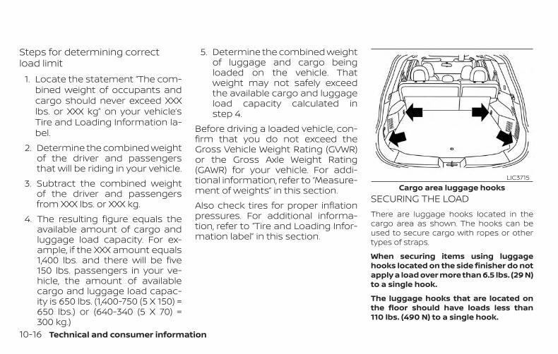
Steps for determining correctload limit
1. Locate the statement “The com-bined weight of occupants andcargo should never exceed XXXlbs. or XXX kg” on your vehicle’sTire and Loading Information la-bel.
2. Determine the combined weightof the driver and passengersthat will be riding in your vehicle.
3. Subtract the combined weightof the driver and passengersfrom XXX lbs. or XXX kg.
4. The resulting figure equals theavailable amount of cargo andluggage load capacity. For ex-ample, if the XXX amount equals1,400 lbs. and there will be five150 lbs. passengers in your ve-hicle, the amount of availablecargo and luggage load capac-ity is 650 lbs. (1,400-750 (5 X 150) =650 lbs.) or (640-340 (5 X 70) =300 kg.)
5. Determine the combined weightof luggage and cargo beingloaded on the vehicle. Thatweight may not safely exceedthe available cargo and luggageload capacity calculated instep 4.
Before driving a loaded vehicle, con-firm that you do not exceed theGross Vehicle Weight Rating (GVWR)or the Gross Axle Weight Rating(GAWR) for your vehicle. For addi-tional information, refer to “Measure-ment of weights” in this section.Also check tires for proper inflationpressures. For additional informa-tion, refer to “Tire and Loading Infor-mation label” in this section.
SECURING THE LOADThere are luggage hooks located in thecargo area as shown. The hooks can beused to secure cargo with ropes or othertypes of straps.
When securing items using luggagehooks located on the side finisher do notapply a load over more than 6.5 lbs. (29 N)to a single hook.
The luggage hooks that are located onthe floor should have loads less than110 lbs. (490 N) to a single hook.
Cargo area luggage hooksLIC3715
10-16 Technical and consumer information

WARNING∙ Properly secure all cargo with ropes or
straps to help prevent it from slidingor shifting. Do not place cargo higherthan the seatbacks. In a sudden stopor collision, unsecured cargo couldcause personal injury.
∙ The child restraint top tether strapmay be damaged by contact withitems in the cargo area. Secure anyitems in the cargo area. Your childcould be seriously injured or killed in acollision if the top tether strap isdamaged.
∙ Do not load your vehicle any heavierthan the GVWR or the maximum frontand rear GAWRs. If you do, parts ofyour vehicle can break, tire damagecould occur, or it can change the wayyour vehicle handles. This could resultin loss of control and cause personalinjury.
LOADING TIPS∙ The GVW must not exceed GVWR
or GAWR as specified on theF.M.V.S.S./C.M.V.S.S. certificationlabel.
∙ Do not load the front and rearaxle to the GAWR. Doing so willexceed the GVWR.
WARNING∙ Properly secure all cargo with
ropes or straps to help preventit from sliding or shifting. Do notplace cargo higher than theseatbacks. In a sudden stop orcollision, unsecured cargo couldcause personal injury.
∙ Do not load your vehicle anyheavier than the GVWR or themaximum front and rearGAWRs. If you do, parts of yourvehicle can break, tire damagecould occur, or it can change theway your vehicle handles. Thiscould result in loss of controland cause personal injury.
∙ Overloading not only canshorten the life of your vehicleand the tire, but can also causeunsafe vehicle handling andlonger braking distances. Thismay cause a premature tire fail-ure which could result in a seri-ous accident and personal in-jury. Failures caused byoverloading are not covered bythe vehicle’s warranty.
MEASUREMENT OF WEIGHTSSecure loose items to preventweight shifts that could affect thebalance of your vehicle. When the ve-hicle is loaded, drive to a scale andweigh the front and the rear wheelsseparately to determine axle loads.Individual axle loads should not ex-ceed either of the GAWR. The total ofthe axle loads should not exceed theGVWR. These ratings are given onthe vehicle certification label. Ifweight ratings are exceeded, moveor remove items to bring all weightsbelow the ratings.
Technical and consumer information 10-17

Do not tow a trailer with your vehicle.
FLAT TOWING FOR ALL–WHEELDRIVE VEHICLE (if so equipped)Towing your vehicle with all four wheels onthe ground is sometimes called flat towing.This method is sometimes used whentowing a vehicle behind a recreational ve-hicle, such as a motor home.
CAUTION∙ Failure to follow these guidelines can
result in severe transmission damage.
∙ Never flat tow your All-wheel drive(AWD) vehicle.
∙ DO NOT tow your All-wheel drive(AWD) vehicle with any wheels on theground. Doing so may cause seriousand expensive damage to thepowertrain.
∙ For emergency towing procedures re-fer to “Towing recommended byNISSAN” in the “In case of emergency”section of this manual.
FLAT TOWING FOR FRONT WHEELDRIVE VEHICLE (if so equipped)Towing your vehicle with all four wheels onthe ground is sometimes called flat towing.This method is sometimes used whentowing a vehicle behind a recreational ve-hicle, such as a motor home.
CAUTION∙ Failure to follow these guidelines can
result in severe transmission damage.
∙ Whenever flat towing your vehicle, al-ways tow forward, never backward.
∙ Never tow your front wheel drive ve-hicle with the front tires on theground. Doing so may cause seriousand expensive damage to thepowertrain.
∙ DO NOT tow your front wheel drivecontinuously variable transmissionvehicle with all four wheels on theground (flat towing). Doing so WILLDAMAGE internal transmission partsdue to lack of transmissionlubrication.
∙ For emergency towing procedures re-fer to “Towing recommended byNISSAN” in the “In case of emergency”section of this manual.
Continuously VariableTransmissionTo tow a vehicle equipped with a continu-ously variable transmission, an appropriatevehicle dolly MUST be placed under thetowed vehicle’s drive wheels. Always followthe dolly manufacturer’s recommenda-tions when using their product.
TOWING A TRAILER
10-18 Technical and consumer information
DOT (Department of Transportation) Qual-ity Grades: All passenger car tires mustconform to federal safety requirements inaddition to these grades.
Quality grades can be found where appli-cable on the tire sidewall between treadshoulder and maximum section width. Forexample:
Treadwear 200 Traction AA Temperature A
Treadwear
The treadwear grade is a comparative rat-ing based on the wear rate of the tire whentested under controlled conditions on aspecified government test course. For ex-ample, a tire graded 150 would wear oneand one-half (1 1/2) times as well on thegovernment course as a tire graded 100.The relative performance of tires dependsupon the actual conditions of their use,however, and may depart significantly fromthe norm due to variations in driving habits,service practices and differences in roadcharacteristics and climate.
Traction AA, A, B and C
The traction grades, from highest to low-est, are AA, A, B, and C. Those grades repre-sent the tire’s ability to stop on wet pave-ment as measured under controlled
conditions on specified government testsurfaces of asphalt and concrete. A tiremarked C may have poor traction perfor-mance.
WARNINGThe traction grade assigned to this tireis based on straight-ahead brakingtraction tests, and does not include ac-celeration, cornering, hydroplaning, orpeak traction characteristics.
Temperature A, B and C
The temperature grades are A (the high-est), B, and C, representing the tire’s resis-tance to the generation of heat, and itsability to dissipate heat when tested undercontrolled conditions on a specified indoorlaboratory test wheel. Sustained high tem-perature can cause the material of the tireto degenerate and reduce tire life, and ex-cessive temperature can lead to suddentire failure. The grade C corresponds to alevel of performance which all passengercar tires must meet under the Federal Mo-tor Vehicle Safety Standard No. 109. GradesB and A represent higher levels of perfor-mance on the laboratory test wheel thanthe minimum required by law.
WARNINGThe temperature grade for this tire isestablished for a tire that is properly in-flated and not overloaded. Excessivespeed, under-inflation, or excessiveloading, either separately or in combi-nation, can cause heat build-up andpossible tire failure.
UNIFORM TIRE QUALITY GRADING
Technical and consumer information 10-19

Your NISSAN vehicle is covered by the fol-lowing emission warranties:
For USA
1. Emission Defects Warranty
2. Emissions Performance Warranty
Details of this warranty may be found withother vehicle warranties in your Warranty In-formation Booklet which comes with yourNISSAN vehicle. If you did not receive a War-ranty Information Booklet, or it is lost, youmay obtain a replacement by writing to:
∙ Nissan North America, Inc.Consumer Affairs DepartmentP.O. Box 685003Franklin, TN 37068-5003
For Canada
Emission Control System Warranty
Details of this warranty may be found withother vehicle warranties in your Warranty In-formation Booklet which comes with yourNISSAN vehicle. If you did not receive a War-ranty Information Booklet, or it is lost, youmay obtain a replacement by writing to:
∙ Nissan Canada Inc.5290 Orbitor DriveMississauga, Ontario, L4W 4Z5
For USA
If you believe that your vehicle has adefect which could cause a crash orcould cause injury or death, youshould immediately inform the Na-tional Highway Traffic Safety Admin-istration (NHTSA) in addition to noti-fying NISSAN.
If NHTSA receives similar complaints,it may open an investigation, and if itfinds that a safety defect exists in agroup of vehicles, it may order a re-call and remedy campaign. However,NHTSA cannot become involved inindividual problems between you,your dealer, or NISSAN.
To contact NHTSA, you may call theVehicle Safety Hotline toll-free at1-888-327-4236 (TTY: 1-800-424-9153);go to http://www.safercar.gov; orwrite to: Administrator, NHTSA, 400Seventh Street, SW., Washington, D.C.20590. You can also obtain other in-formation about motor vehicle safetyfrom http://www.safercar.gov.
You may notify NISSAN by contact-ing our Consumer Affairs Depart-ment, toll-free, at 1-800-NISSAN-1.
For Canada
If you believe that your vehicle has adefect which could cause a crash orcould cause injury or death, youshould immediately inform Trans-port Canada in addition to notifyingNISSAN.If Transport Canada receives com-plaints, it may open an investigation,and if it finds that a safety defectexists in a group of vehicles, it mayrequest that NISSAN conduct a recallcampaign. However, TransportCanada cannot become involved inindividual problems between you,your dealer, or NISSAN.You may contact Transport Canada’sDefect Investigations and Recalls Divi-sion toll free at 1-800-333-0510. Youmay also report safety defects onlineat: https://wwwapps.tc.gc.ca/Saf-Sec-Sur/7/PCDB-BDPP/fc-
EMISSION CONTROL SYSTEMWARRANTY
REPORTING SAFETY DEFECTS
10-20 Technical and consumer information

cp.aspx?lang=eng (English speakers)or https://wwwapps.tc.gc.ca/Saf-Sec-Sur/7/PCDB-BDPP/fc-cp.aspx?lang=fra (French speakers)Additional information concerningmotor vehicle safety may be ob-tained from Transport Canada’sRoad Safety Information Centre at1-800-333-0371 or online atwww.tc.gc.ca/roadsafety (Englishspeakers) orwww.tc.gc.ca/securiteroutiere(French speakers).To notify NISSAN of any safety con-cerns please contact our ConsumerInformation Centre toll free at 1-800-387-0122.
WARNINGA vehicle equipped with All -Wheel Drive(AWD) should never be tested using atwo wheel dynamometer (such as thedynamometers used by some states foremissions testing), or similar equip-ment. Make sure you inform the test fa-cility personnel that your vehicle isequipped with AWD before it is placedon a dynamometer. Using the wrongtest equipment may result in drivetraindamage or unexpected vehicle move-ment which could result in serious ve-hicle damage or personal injury.
Due to legal requirements in some statesand Canadian Provinces, your vehicle maybe required to be in what is called the“ready condition” for anInspection/Maintenance (I/M) test of theemission control system.
The vehicle is set to the “ready condition”when it is driven through certain drivingpatterns. Usually, the ready condition canbe obtained by ordinary usage of the ve-hicle.
If a powertrain system component is re-paired or the battery is disconnected, thevehicle may be reset to a “not ready” condi-tion. Before taking the I/M test, check thevehicle’s inspection/maintenance testreadiness condition. Place the ignitionswitch in the ON position without startingthe engine. If the Malfunction IndicatorLight (MIL) comes on steady for 20 secondsand then blinks for 10 seconds , the I/M testcondition is “not ready”. If the MIL does notblink after 20 seconds, the I/M test condi-tion is “ready”. It is recommended that youvisit a NISSAN dealer to set the “ready con-dition” or to prepare the vehicle for testing.
READINESS FOR INSPECTION/MAINTENANCE (I/M) TEST
Technical and consumer information 10-21
This vehicle is equipped with an Event DataRecorder (EDR). The main purpose of anEDR is to record, in certain crash or nearcrash-like situations, such as an air bagdeployment or hitting a road obstacle, datathat will assist in understanding how a ve-hicle’s systems performed. The EDR is de-signed to record data related to vehicle dy-namics and safety systems for a shortperiod of time, typically 30 seconds or less.The EDR in this vehicle is designed to re-cord such data as:
∙ How various systems in your vehiclewere operating;
∙ Whether or not the driver and passen-ger safety belts were buckled/fastened;
∙ How far (if at all) the driver was depress-ing the accelerator and/or brake pedal;and,
∙ How fast the vehicle was traveling.
∙ Sounds are not recorded.
These data can help provide a better un-derstanding of the circumstances in whichcrashes and injuries occur. NOTE: EDR dataare recorded by your vehicle only if a non-trivial crash situation occurs; no data arerecorded by the EDR under normal drivingconditions and no personal data (e.g.name, gender, age and crash location) arerecorded. However, other parties, such aslaw enforcement, could combine the EDRdata with the type of personally identifyingdata routinely acquired during a crash in-vestigation.
To read data recorded by an EDR, specialequipment is required and access to thevehicle or the EDR is needed. In addition tothe vehicle manufacturer and NISSANdealer, other parties, such as law enforce-ment, that have the special equipment, canread the information if they have access tothe vehicle or the EDR. EDR data will only beaccessed with the consent of the vehicleowner or lessee or as otherwise required orpermitted by law.
Genuine NISSAN Service Manuals for thismodel year and prior can be purchased. AGenuine NISSAN Service Manual is the bestsource of service and repair information foryour vehicle. This manual is the same oneused by the factory-trained techniciansworking at NISSAN dealerships. GenuineNISSAN Owner’s Manuals can also be pur-chased.
For USA
For current pricing and availability of Genu-ine NISSAN Service Manuals, contact:
www.nissan-techinfo.com
For current pricing and availability of Genu-ine NISSAN Owner’s Manuals, contact:
1-800-247-5321
For Canada
To purchase a copy of a Genuine NISSANService Manual or Owner’s Manual, for thismodel year and prior, please contact thenearest NISSAN dealer. For the phone num-ber and location of a NISSAN dealer in yourarea, call the NISSAN Information Center at1-800-387-0122 and a bilingual NISSAN rep-resentative will assist you.
EVENT DATA RECORDERS (EDR) OWNER’S MANUAL/SERVICEMANUAL ORDER INFORMATION
10-22 Technical and consumer information

11 Index12-volt battery . . . . . . . . . . . . . . . .5-124
A
Active Ride Control (ARC) . . . . . . . . . .5-117Air bag (See supplemental restraintsystem) . . . . . . . . . . . . . . . . . . . . .1-45Air bag system
Front (See supplemental front impactair bag system) . . . . . . . . . . . . . .1-52
Air bag warning labels . . . . . . . . . . . .1-63Air bag warning light. . . . . . . . . .1-64, 2-16Air bag warning light,supplemental . . . . . . . . . . . . . .1-64, 2-16Air cleaner housing filter . . . . . . . . . .8-15Air conditioner
Air conditioner operation . . . . . . . .4-31Air conditioner specification label . .10-13Air conditioner system refrigerant and oilrecommendations . . . . . . . . . . . .10-8Air conditioner system refrigerantrecommendations . . . . . . . . . . . .10-8Heater and air conditioner controls. .4-31Servicing air conditioner . . . . . . . .4-34
Alarm system(See vehicle security system) . . . . . . .2-40All-Wheel Drive . . . . . . . . . . . . .5-105, 6-17All-Wheel Drive (AWD) LOCK switch . . .5-106Anchor point locations . . . . . . . . . . .1-28Antenna . . . . . . . . . . . . . . . . . . . .4-35Antifreeze . . . . . . . . . . . . . . . . . . .5-124Anti-lock brake warning light . . . . . . . .2-11
Anti-lock Braking System (ABS) . . . . . .5-111Approaching Vehicle Sound for Pedestrians(VSP) System . . . . . . . . . . . . . . . .HEV-11Armrests . . . . . . . . . . . . . . . . . . . . .1-5Assist charge gauge . . . . . . . . . . . . .2-7Audible reminders . . . . . . . . . . . . . .2-20Autolight switch . . . . . . . . . . . . . . .2-46Automatic
Automatic drive positioner . . . .3-39, 3-41Automatic power window switch. . .2-69
Automatic anti-glare inside mirror . . . .3-36Automatic door locks . . . . . . . . . . . . .3-6Automatic drive positioner . . . . . .3-39, 3-41Automatic Emergency Braking(AEB). . . . . . . . . . . . . .2-11, 2-12, 2-16, 5-81Automatic Emergency Braking (AEB) withPedestrian Detection . . . . . . . . . . . .5-89AWD . . . . . . . . . . . . . . . . . . .5-105, 6-17
B
Battery . . . . . . . . . . . . . . . . . . . . .8-13Charge warning light . . . . . . . . . . .2-11
Battery replacement . . . . . . . . . . . .8-22Key fob . . . . . . . . . . . . . . . . . . .8-22NISSAN Intelligent Key® . . . . . . . . .8-22
Before starting the NISSAN PURE DRIVE®Hybrid System . . . . . . . . . . . . . . . . .5-17Blind Spot Warning (BSW) . . . . . . . . . .5-37Booster seats . . . . . . . . . . . . . . . . .1-41Brake
Anti-lock Braking System (ABS) . . . .5-111
Brake fluid . . . . . . . . . . . . . . . . .8-11Brake light (See stop light) . . . . . . .8-25Brake system. . . . . . . . . . . . . . .5-110Brake warning light. . . . . . . . . . . .2-12Brake wear indicators. . . . . . .2-20, 8-19Parking brake operation . . . . . . . .5-24Self-adjusting brakes . . . . . . . . . .8-19
Brake Assist . . . . . . . . . . . . . . . . . .5-112Brake fluid . . . . . . . . . . . . . . . . . . .8-11Brakes. . . . . . . . . . . . . . . . . . . . . .8-19Brake system. . . . . . . . . . . . . . . . .5-110Break-in schedule . . . . . . . . . . . . . .5-103Brightness control
Instrument panel . . . . . . . . . . . . .2-51Bulb check/instrument panel . . . . . . .2-11Bulb replacement . . . . . . . . . . . . . .8-25
C
Capacities and recommended fuel/lubricants. . . . . . . . . . . . . . . . . . . .10-2Cargo area storage bin . . . . . . . . . . .2-64Cargo cover . . . . . . . . . . . . . . . . . .2-65Cargo light . . . . . . . . . . . . . . . . . . .2-74Cargo(See vehicle loading information) . . . .10-14Car phone or CB radio. . . . . . . . . . . .4-35Chassis control. . . . . . . . . . . . . . . .5-115Checking bulbs . . . . . . . . . . . . . . . .2-11Check tire pressure . . . . . . . . . . . . .2-35Child restraints . . . . . . .1-20, 1-21, 1-23, 1-25

LATCH (Lower Anchors and Tethers forCHildren) System. . . . . . . . . . . . . .1-25Precautions on childrestraints . . . . . . . . .1-23, 1-30, 1-36, 1-41Top tether strap anchor pointlocations. . . . . . . . . . . . . . . . . . .1-28
Child restraint with top tether strap . . . .1-27Child safety rear door lock . . . . . . . . . .3-7Chimes, audible reminders . . . . . . . . .2-20Cleaning exterior and interior . . . . . .7-2, 7-4C.M.V.S.S. certification label . . . . . . . . .10-12Cold weather driving . . . . . . . . . . . .5-124Console box. . . . . . . . . . . . . . . . . . .2-61Console light . . . . . . . . . . . . . . . . . .2-73Continuously Variable Transmission(CVT) . . . . . . . . . . . . . . . . . . . . . . .5-19
Continuously Variable Transmission(CVT) fluid . . . . . . . . . . . . . . . . . .8-11Driving with Continuously VariableTransmission (CVT) . . . . . . . . . . . .5-19
ControlsHeater and air conditioner controls . .4-31
CoolantCapacities and recommendedfuel/lubricants . . . . . . . . . . . . . . .10-2Changing engine coolant . . . . . . . . .8-5Checking engine coolant level . . . . . .8-5Checking inverter coolant level . . . . .8-7
Corrosion protection . . . . . . . . . . . . . .7-7Cruise control . . . . . . . . . . . . . . . . .5-55Cup holders. . . . . . . . . . . . . . . . . . .2-62
D
Defroster switchRear window and outside mirrordefroster switch . . . . . . . . . . . . . .2-45
Dimensions and weights . . . . . . . . . .10-10Dimmer switch for instrument panel . . .2-51Display . . . . . . . . . . . . . . . . . . . . . .2-21Door locks . . . . . . . . . . . . . . . . . .3-4, 3-5Drive positioner, Automatic . . . . . .3-39, 3-41Driving
Cold weather driving . . . . . . . . . .5-124Driving with Continuously VariableTransmission (CVT) . . . . . . . . . . . .5-19Precautions when starting anddriving. . . . . . . . . . . . . . . . . .5-4, 5-12
Driving the vehicle . . . . . . . . . . . . . . .5-19Dynamic driver assistance switch . . . .2-54
E
E-CALL (SOS) SWITCH . . . . . . . . . . . . .2-57ECO mode switch . . . . . . . . . . . . . . .5-25Economy - fuel . . . . . . . . . . . . . . . .5-105Efficient use of your vehicle . . . . . . . .HEV-11Emergency hybrid system shut off . . . .5-16Emergency shut-off system . . . . . . .HEV-4Emission control information label . . . .10-12Emission control system warranty . . . .10-20Energy monitors. . . . . . . . . . . . . . .HEV-6Engine
Capacities and recommendedfuel/lubricants . . . . . . . . . . . . . . .10-2Changing engine coolant . . . . . . . . .8-5Changing engine oil . . . . . . . . . . . .8-8
Changing engine oil filter. . . . . . . . .8-10Checking engine coolant level . . . . . .8-5Checking engine oil level . . . . . . . . .8-7Engine compartment checklocations . . . . . . . . . . . . . . . . . . .8-3Engine cooling system . . . . . . . . . .8-4Engine oil . . . . . . . . . . . . . . . . . . .8-7Engine oil and oil filterrecommendation . . . . . . . . . . . . .10-7Engine oil viscosity. . . . . . . . . . . . .10-7Engine serial number . . . . . . . . . .10-12Engine specifications . . . . . . . . . . .10-9
Event Data recorders . . . . . . . . . . . .10-22Exhaust gas (Carbon monoxide). . . . . . .5-4Explanation of maintenance items . . . . .9-2Explanation of scheduled maintenanceitems . . . . . . . . . . . . . . . . . . . . . . .9-5Extended storage switch . . . . . . . . . .2-59Eyeglass case . . . . . . . . . . . . . . . . .2-62
F
Flashers(See hazard warning flasher switch) . . . .6-2Flat tire . . . . . . . . . . . . . . . . . . . . . .6-3Floor mat positioning aid . . . . . . . . . . .7-6Fluid
Brake fluid . . . . . . . . . . . . . . . . . .8-11Capacities and recommendedfuel/lubricants . . . . . . . . . . . . . . .10-2Continuously Variable Transmission(CVT) fluid . . . . . . . . . . . . . . . . . .8-11Engine coolant . . . . . . . . . . . . . . .8-4Engine oil . . . . . . . . . . . . . . . . . . .8-7
11-2
Inverter coolant . . . . . . . . . . . . . . .8-6Windshield-washer fluid . . . . . . . . .8-12
F.M.V.S.S. certification label . . . . . . . . .10-12Fog light switch . . . . . . . . . . . . . . . .2-52Front air bag system(See supplemental restraint system) . . .1-52Front-door pocket . . . . . . . . . . . . . .2-60Front power seat adjustment . . . . . . . .1-4Front seats . . . . . . . . . . . . . . . . . . . .1-2Fuel
Capacities and recommendedfuel/lubricants . . . . . . . . . . . . . . .10-2Fuel economy . . . . . . . . . . . . . . .5-105Fuel-filler door and cap . . . . . . . . . .3-31Fuel gauge . . . . . . . . . . . . . . . . . .2-6Fuel octane rating . . . . . . . . . . . . .10-6Fuel recommendation . . . . . . . . . .10-4Loose fuel cap warning . . . . . . . . .2-35
Fuel efficient driving tips . . . . . . . . . .5-104Fuel-filler door . . . . . . . . . . . . . . . . .3-31Fuel gauge . . . . . . . . . . . . . . . . . . . .2-6Fuses . . . . . . . . . . . . . . . . . . . . . .8-20Fusible links. . . . . . . . . . . . . . . . . . .8-20
G
Garage door opener, HomeLink® UniversalTransceiver . . . . . .2-75, 2-76, 2-77, 2-78, 2-78Gas cap . . . . . . . . . . . . . . . . . . . . .3-31Gauge
Fuel gauge . . . . . . . . . . . . . . . . . .2-6Odometer . . . . . . . . . . . . . . . . . .2-5Power meter . . . . . . . . . . . . . . . . .2-7Speedometer . . . . . . . . . . . . . . . .2-4
Tachometer . . . . . . . . . . . . . . . . .2-6Trip odometer . . . . . . . . . . . . . . . .2-5
General maintenance . . . . . . . . . . . . .9-2Glove box . . . . . . . . . . . . . . . . . . . .2-61
H
Hazard warning flasher switch. . . . . . . .6-2Headlight and turn signal switch. . . . . .2-46Headlight control switch . . . . . . . . . . .2-46Headlights . . . . . . . . . . . . . . . . . . .8-23Head restraints. . . . . . . . . . . . . . . . . .1-7Heated seats . . . . . . . . . . . . . . . . . .2-53Heated steering wheel switch . . . . . . .2-54Heater
Heater and air conditioner controls . .4-31Heater operation . . . . . . . . . . . . .4-32
High-voltage cautions . . . . . . . . . . .HEV-3High voltage components . . . . . . . .HEV-12Hill start assist system. . . . . . . . . . . .5-118HomeLink® UniversalTransceiver . . . . . .2-75, 2-76, 2-77, 2-78, 2-78Hood . . . . . . . . . . . . . . . . . . . . . . .3-23Hook
Luggage hook . . . . . . . . . . . . . . .2-64Horn . . . . . . . . . . . . . . . . . . . . . . .2-52Hybrid System
Stops operating while driving . . . . . .6-11Vehicle does not start . . . . . . . . . . .6-11
Hybrid vehicle characteristics . . . . . .HEV-13Hybrid vehicle precautions . . . . . . . .HEV-12
I
Ignition switchPush-button ignition switch . . . . . . .5-14
Immobilizer system. . . . . . . . . . .2-42, 5-17Important vehicle information label . . .10-12In-cabin microfilter . . . . . . . . . . . . . .8-16Increasing fuel economy . . . . . . . . . .5-105Indicator
NISSAN Intelligent Key® battery dischargeindicator . . . . . . . . . . . . . . . . . . .5-16
Indicator lights and audible reminders(See warning/indicator lights and audiblereminders) . . . . . . . . . . . . . .2-10, 2-11, 2-17Information display . . . . . . . . . . . . . .2-21Inside automatic anti-glare mirror. . . . .3-36Instrument brightness control . . . . . . .2-51Instrument panel . . . . . . . . . . . . .0-6, 2-2Instrument panel dimmer switch . . . . .2-51Intelligent Around View Monitor . . . . . . .4-11Intelligent Cruise Control (ICC) . . . . . . .5-57Intelligent Engine Brake (I-EB) . . . . . . .5-116Intelligent Key system
Key operating range . . . . . . . . . . . .3-9Key operation . . . . . . . . . . . . . . . .3-10Mechanical key . . . . . . . . . . . . . . .3-3Remote keyless entry operation . . . .3-13Troubleshooting guide . . . . . . . . . .3-18Warning signals . . . . . . . . . . . . . .3-18
Intelligent Lane Intervention (I-LI) . . . . . .5-31Intelligent Trace Control (I-TC) . . . . . . .5-115Interior light . . . . . . . . . . . . . . .2-72, 2-74Inverter
Checking inverter coolant level . . . . .8-7Inverter cooling system . . . . . . . . . .8-6
11-3

ISOFIX child restraints . . . . . . . . . . . . .1-25
J
Jump starting . . . . . . . . . . . . . .6-12, 8-14
K
Key . . . . . . . . . . . . . . . . . . . . . . . . .3-2Key fob battery replacement . . . . . . . .8-22Keyless entry
With Intelligent Key system(See Intelligent Key system) . . . . . . .3-13
KeysNISSAN Intelligent Key® . . . . . . . .3-2, 3-7NISSAN Vehicle Immobilizer Systemkeys . . . . . . . . . . . . . . . . . . . . . .3-4
L
LabelTire and Loading Information label . .10-13
LabelsAir conditioner specification label . . .10-13C.M.V.S.S. certification label . . . . . . .10-12Emission control information label . .10-12Engine serial number . . . . . . . . . .10-12F.M.V.S.S. certification label . . . . . . .10-12Tire and Loading Information label . .10-13Vehicle identification number (VIN) . .10-11Vehicle identification number (VIN)plate . . . . . . . . . . . . . . . . . . . . .10-11Warning labels (for SRS). . . . . . . . . .1-63
Lane Departure Warning (LDW) . . . . . . .5-26LATCH (Lower Anchors and Tethers forCHildren) System. . . . . . . . . . . . . . . .1-25LED Daytime Running Lights (DRL)system. . . . . . . . . . . . . . . . . . . . . .2-50License plate
Installing the license plate . . . . . . .10-13Liftgate . . . . . . . . . . . . . . . . . . . . .3-24Liftgate release . . . . . . . . . . . . . . . .3-29Light
Air bag warning light . . . . . . . .1-64, 2-16Brake light (See stop light) . . . . . . . .8-25Bulb check/instrument panel . . . . . .2-11Bulb replacement . . . . . . . . . . . . .8-25Charge warning light . . . . . . . . . . .2-11Console light . . . . . . . . . . . . . . . .2-73Exterior and Interior lights . . . . . . . .8-25Fog lights . . . . . . . . . . . . . . . . . .8-24Fog light switch . . . . . . . . . . . . . .2-52Headlight and turn signal switch. . . .2-46Headlight control switch . . . . . . . . .2-46Headlights . . . . . . . . . . . . . . . . .8-23Interior light . . . . . . . . . . . . .2-72, 2-74Light bulbs . . . . . . . . . . . . . . . . .8-23Low tire pressure warning light . . . . .2-13Low windshield-washer fluid warninglight. . . . . . . . . . . . . . . . . . . . . .2-34Passenger air bag and status light. . .1-55Personal lights . . . . . . . . . . . . . . .2-73Security indicator light . . . . . . . . . .2-19Spotlights (See map light) . . . . . . . .2-73Warning/indicator lights and audiblereminders . . . . . . . . . . . .2-10, 2-11, 2-17
Lights . . . . . . . . . . . . . . . . . . . . . .8-23Map lights . . . . . . . . . . . . . . . . . .2-73
Lithium-ion (Li-ion) Battery . . . . . . . .HEV-2
LockChild safety rear door lock . . . . . . . .3-7Door locks . . . . . . . . . . . . . . . .3-4, 3-5Liftgate release . . . . . . . . . . . . . .3-29Power door locks . . . . . . . . . . . . . .3-6
Loose fuel cap warning . . . . . . . .2-35, 3-33Low fuel warning light . . . . . .2-15, 2-16, 2-34Low tire pressure warning light . . . . . . .2-13Low windshield-washer fluid warninglight. . . . . . . . . . . . . . . . . . . . . . . .2-34Luggage hook . . . . . . . . . . . . . . . . .2-64Luggage rack (see roof rack) . . . . . . . .2-66Luggage(See vehicle loading information) . . . . .10-14Luggage storage (see vehicle loadinginformation) . . . . . . . . . . . . . . . . . .2-64
M
MaintenanceGeneral maintenance . . . . . . . . . . .9-2Inside the vehicle . . . . . . . . . . . . . .9-3Maintenance precautions. . . . . . . . .8-2Outside the vehicle . . . . . . . . . . . . .9-2Seat belt maintenance . . . . . . . . . .1-20Under the hood and vehicle . . . . . . .9-4
Maintenance log . . . . . . . . . . . . . . . .9-15Maintenance requirements. . . . . . . . . .9-2Maintenance schedules . . . . . . . . . . . .9-7Maintenance under severe operationconditions . . . . . . . . . . . . . . . . . . . .9-12Malfunction indicator light . . . . . . . . . .2-18Manual front seat adjustment . . . . . . . .1-3Map lights . . . . . . . . . . . . . . . . . . . .2-73Memory Seat . . . . . . . . . . . . . . .3-39, 3-41
11-4

Meters and gauges. . . . . . . . . . . . . . .2-4Instrument brightness control . . . . .2-51
MirrorAutomatic anti-glare inside mirror. . .3-36Outside mirrors . . . . . . . . . . . . . .3-38Rearview. . . . . . . . . . . . . . . . . . .3-36Vanity mirror . . . . . . . . . . . . . . . .3-35
Mirrors . . . . . . . . . . . . . . . . . . . . . .3-36Moonroof . . . . . . . . . . . . . . . . . .2-70, 7-5Moving Object Detection (MOD) . . . . . .4-24
N
NissanConnect® Owner's Manual . . . . . .4-2NISSAN Intelligent Key® . . . . . . . . . .3-2, 3-7NISSAN Intelligent Key® battery dischargeindicator . . . . . . . . . . . . . . . . . . . . .5-16NISSAN PURE DRIVE® Hybrid System . .HEV-2NISSAN Vehicle ImmobilizerSystem . . . . . . . . . . . . . . . . . .2-42, 5-17
O
Octane rating (See fuel octane rating) . .10-6Odometer . . . . . . . . . . . . . . . . . . . .2-5Oil
Capacities and recommendedfuel/lubricants . . . . . . . . . . . . . . .10-2Changing engine oil . . . . . . . . . . . .8-8Changing engine oil filter. . . . . . . . .8-10Checking engine oil level . . . . . . . . .8-7Engine oil . . . . . . . . . . . . . . . . . . .8-7Engine oil and oil filterrecommendation . . . . . . . . . . . . .10-7
Engine oil viscosity. . . . . . . . . . . . .10-7Operation of the hybrid system . . . . .HEV-5Outside mirrors . . . . . . . . . . . . . . . .3-38Overhead sunglasses holder . . . . . . . .2-62Owner's manual order form . . . . . . . .10-22Owner's manual/service manual orderinformation . . . . . . . . . . . . . . . . . .10-22
P
ParkingParking brake operation . . . . . . . . .5-24Parking/parking on hills. . . . . . . . .5-109
Parking brake . . . . . . . . . . . . . . . . .5-24Personal lights . . . . . . . . . . . . . . . . .2-73Power
Power door locks . . . . . . . . . . . . . .3-6Power outlet . . . . . . . . . . . . . . . .2-57Power rear windows . . . . . . . . . . .2-69Power steering system . . . . . . . . .5-109Power windows . . . . . . . . . . . . . .2-67Rear power windows . . . . . . . . . . .2-69
Power meter . . . . . . . . . . . . . . . . . . .2-7Power outlet . . . . . . . . . . . . . . . . . .2-57Power steering . . . . . . . . . . . . . . . .5-109Precautions
Maintenance precautions. . . . . . . . .8-2On-pavement and off-road drivingprecautions . . . . . . . . . . . . . . . . .5-9Precautions on boosterseats . . . . . . . . . . . .1-23, 1-30, 1-36, 1-41Precautions on childrestraints . . . . . . . . .1-23, 1-30, 1-36, 1-41Precautions on seat belt usage . . . . .1-11
Precautions on supplemental restraintsystem . . . . . . . . . . . . . . . . . . . .1-45Precautions when starting anddriving. . . . . . . . . . . . . . . . . .5-4, 5-12
Push starting . . . . . . . . . . . . . . . . . .6-14
R
RadioCar phone or CB radio . . . . . . . . . .4-35
Readiness for inspection maintenance(I/M) test . . . . . . . . . . . . . . . . . . . .10-21Rear Automatic Braking (RAB) . . . . . . .5-98Rear Cross Traffic Alert (RCTA). . . . . . . .5-47Rear Door Alert . . . . . . . . . . . . .2-39, 2-56Rear power windows . . . . . . . . . . . . .2-69Rear Sonar System (RSS) . . . . . . . . . .5-119Rearview mirror . . . . . . . . . . . . . . . .3-36RearView Monitor . . . . . . . . . . . . . . . .4-3
Adjusting the screen . . . . . . . . . . . .4-9Rear window and outside mirror defrosterswitch . . . . . . . . . . . . . . . . . . . . . .2-45Rear window wiper and washerswitches. . . . . . . . . . . . . . . . . . . . .2-44Recommended Fluids . . . . . . . . . . . .10-2Recorders
Event Data . . . . . . . . . . . . . . . . .10-22Refrigerant recommendation. . . . . . . .10-8Regenerative brake . . . . . . . . . . . .HEV-10Registering a vehicle in anothercountry . . . . . . . . . . . . . . . . . . . . .10-11Remote Hybrid Start . . . . . . . . . . . . .5-18Remote Start . . . . . . . . . . . . . . . . . .3-20Reporting safety defects (US only) . . . .10-20
11-5
Road accident cautions . . . . . . . . . .HEV-3Roof rack . . . . . . . . . . . . . . . . . . . .2-66
S
SafetyChild safety rear door lock . . . . . . . .3-7Child seat belts . . . . . .1-23, 1-30, 1-36, 1-41Reporting safety defects (US only) . .10-20
Seat adjustmentFront manual seat adjustment . . . . . .1-3Front power seat adjustment . . . . . .1-4
Seatback pockets . . . . . . . . . . . . . . .2-60Seat belt
Child safety . . . . . . . . . . . . . . . . .1-20Infants and small children . . . . . . . .1-21Injured Person. . . . . . . . . . . . . . . .1-14Larger children . . . . . . . . . . . . . . .1-21Precautions on seat belt usage . . . . .1-11Pregnant women. . . . . . . . . . . . . .1-14Seat belt extenders . . . . . . . . . . . .1-19Seat belt maintenance . . . . . . . . . .1-20Seat belts . . . . . . . . . . . . . . . .1-11, 7-7Shoulder belt height adjustment . . . .1-18Three-point type with retractor . . . . .1-14
Seat belt extenders . . . . . . . . . . . . . .1-19Seat belt warning light . . . . . . . . .1-14, 2-16Seats
Adjustment . . . . . . . . . . . . . . . . . .1-2Armrests . . . . . . . . . . . . . . . . . . .1-5Automatic drive positioner . . . .3-39, 3-41Front seats . . . . . . . . . . . . . . . . . .1-2Heated seats . . . . . . . . . . . . . . . .2-53Manual front seat adjustment . . . . . .1-3
Seats/floor mats . . . . . . . . . . . . . . . .7-6
Security indicator light . . . . . . . . . . . .2-19Security system (NISSAN Vehicle ImmobilizerSystem), engine start . . . . . . . . . .2-42, 5-17Security systems
Vehicle security system . . . . . . . . .2-40Self-adjusting brakes . . . . . . . . . . . . .8-19Service manual order form. . . . . . . . .10-22Servicing air conditioner . . . . . . . . . . .4-34Shoulder belt height adjustment . . . . . .1-18Sonar
Rear system . . . . . . . . . . . . . . . .5-119Spark plug replacement . . . . . . . . . . .8-14Spark plugs . . . . . . . . . . . . . . . . . . .8-14Specifications. . . . . . . . . . . . . . . . . .10-9Speedometer . . . . . . . . . . . . . . . . . .2-4Speedometer and odometer . . . . . . . .2-4SPORT mode switch . . . . . . . . . . . . .5-25Spotlights (See map light) . . . . . . . . . .2-73SRS warning label . . . . . . . . . . . . . . .1-63Standard maintenance . . . . . . . . . . . .9-8Starting
Jump starting . . . . . . . . . . . .6-12, 8-14Precautions when starting anddriving. . . . . . . . . . . . . . . . . .5-4, 5-12Push starting . . . . . . . . . . . . . . . .6-14
Starting the NISSAN PURE DRIVE® HybridSystem. . . . . . . . . . . . . . . . . . . . . .5-18Steering
Power steering system . . . . . . . . .5-109Steering wheel . . . . . . . . . . . . . . . . .3-34Stop light . . . . . . . . . . . . . . . . . . . .8-25Storage . . . . . . . . . . . . . . . . . . . . .2-60Storage bin . . . . . . . . . . . . . . . . . . .2-64Sunglasses case. . . . . . . . . . . . . . . .2-62Sunglasses holder . . . . . . . . . . . . . .2-62
Sunroof . . . . . . . . . . . . . . . . . . .2-70, 7-5Sunroof (see Moonroof) . . . . . . . . . . .2-70Sun visors . . . . . . . . . . . . . . . . . . . .3-34Supplemental air bag warning labels . . .1-63Supplemental air bag warninglight. . . . . . . . . . . . . . . . . . . . .1-64, 2-16Supplemental front impact air bagsystem . . . . . . . . . . . . . . . . . . . . . .1-52Supplemental restraint system
Information and warning labels . . . .1-63Precautions on supplemental restraintsystem . . . . . . . . . . . . . . . . . . . .1-45
Supplemental restraint system(Supplemental air bag system) . . . . . . .1-45Switch
Autolight switch . . . . . . . . . . . . . .2-46Automatic power window switch . . .2-69Fog light switch . . . . . . . . . . . . . .2-52Hazard warning flasher switch. . . . . .6-2Headlight and turn signal switch. . . .2-46Headlight control switch . . . . . . . . .2-46Instrument brightness control . . . . .2-51Power door lock switch . . . . . . . . . .3-6Rear window and outside mirrordefroster switch . . . . . . . . . . . . . .2-45Rear window wiper and washerswitches. . . . . . . . . . . . . . . . . . .2-44Turn signal switch . . . . . . . . . . . . .2-51
T
Tachometer . . . . . . . . . . . . . . . . . . .2-6Theft (NISSAN Vehicle Immobilizer System),engine start . . . . . . . . . . . . . . .2-42, 5-17Three-way catalyst . . . . . . . . . . . . . . .5-5
11-6
TireFlat tire . . . . . . . . . . . . . . . . . . . .6-3Spare tire. . . . . . . . . . . . . . . .6-5, 8-39Tire and Loading Information label . .10-13Tire chains . . . . . . . . . . . . . . . . .8-35Tire pressure . . . . . . . . . . . . . . . .8-28Tire rotation . . . . . . . . . . . . . . . .8-36Types of tires . . . . . . . . . . . . . . . .8-34Uniform tire quality grading . . . . . .10-19Wheels and tires . . . . . . . . . . . . . .8-28Wheel/tire size. . . . . . . . . . . . . . .10-10
Tire pressureLow tire pressure warning light . . . . .2-13
Tire Pressure Monitoring System (TPMS) . .5-5Top tether strap child restraint . . . . . . .1-27Towing
4-wheel drive models . . . . . . . . . . .6-18Flat towing . . . . . . . . . . . . . . . . .10-18Tow truck towing . . . . . . . . . . . . .6-16Trailer towing . . . . . . . . . . . . . . .10-18
Towing a trailer . . . . . . . . . . . . . . . .10-18Transceiver
HomeLink® UniversalTransceiver . . . .2-75, 2-76, 2-77, 2-78, 2-78
TransmissionContinuously Variable Transmission(CVT) fluid . . . . . . . . . . . . . . . . . .8-11Driving with Continuously VariableTransmission (CVT) . . . . . . . . . . . .5-19
Travel (See registering a vehicle in anothercountry) . . . . . . . . . . . . . . . . . . . . .10-11Trip odometer . . . . . . . . . . . . . . . . . .2-5Turn signal switch . . . . . . . . . . . . . . .2-51
U
Uniform tire quality grading . . . . . . . .10-19USB/iPod® Charging Ports. . . . . . . . . .4-35
V
Vanity mirror . . . . . . . . . . . . . . . . . .3-35Vehicle dimensions and weights . . . . .10-10Vehicle does not start . . . . . . . . . . . . .6-11Vehicle Dynamic Control (VDC) OFFswitch . . . . . . . . . . . . . . . . . . . . . .2-55Vehicle Dynamic Control (VDC)system . . . . . . . . . . . . . . . . . . . . .5-112Vehicle identification . . . . . . . . . . . . .10-11Vehicle identification number (VIN) . . . .10-11Vehicle identification number (VIN)(Chassis number) . . . . . . . . . . . . . . .10-11Vehicle identification number (VIN)plate . . . . . . . . . . . . . . . . . . . . . . .10-11Vehicle immobilizer system . . . . . .2-42, 5-17Vehicle Information Display . . . . . . . . .2-21Vehicle loading information . . . . . . . .10-14Vehicle recovery . . . . . . . . . . . . .6-18, 6-19Vehicle security system . . . . . . . . . . .2-40Vehicle security system (NISSAN VehicleImmobilizer System), engine start . .2-42, 5-17Ventilators . . . . . . . . . . . . . . . . . . .4-29Visors . . . . . . . . . . . . . . . . . . . . . .3-34
W
WarningAir bag warning light . . . . . . . .1-64, 2-16Anti-lock brake warning light . . . . . .2-11Battery charge warning light . . . . . .2-11Brake warning light . . . . . . . . . . . .2-12Hazard warning flasher switch. . . . . .6-2Loose fuel cap warning . . . . . .2-35, 3-33Low fuel warning light . . . .2-15, 2-16, 2-34Low tire pressure warning light . . . . .2-13Low windshield-washer fluid warninglight. . . . . . . . . . . . . . . . . . . . . .2-34Passenger air bag and status light. . .1-55Seat belt warning light . . . . . . .1-14, 2-16Supplemental air bag warninglight. . . . . . . . . . . . . . . . . . .1-64, 2-16TPMS. . . . . . . . . . . . . . . . . . . . . .2-4Vehicle security system . . . . . . . . .2-40Warning/indicator lights and audiblereminders . . . . . . . . . . . .2-10, 2-11, 2-17Warning labels (for SRS). . . . . . . . . .1-63
Warning/indicator lights and audiblereminders . . . . . . . . . . . . . .2-10, 2-11, 2-17
Audible reminders . . . . . . .2-10, 2-11, 2-17Checking bulbs . . . . . . . . . . . . . . .2-11Indicator lights . . . . . . . . .2-10, 2-11, 2-17Warning lights. . . . . . . . . .2-10, 2-11, 2-17
Warning lights. . . . . . . . . . . .2-10, 2-11, 2-17Warning lights, indicator lights and audiblereminders . . . . . . . . . . . . . . . . . . . .2-10
11-7

Washer switchRear window wiper and washerswitches. . . . . . . . . . . . . . . . . . .2-44
Weights(See dimensions and weights) . . . . . . .10-10Wheels and tires . . . . . . . . . . . . . . . .8-28Wheel/tire size. . . . . . . . . . . . . . . . .10-10When traveling or registering in anothercountry . . . . . . . . . . . . . . . . . . . . .10-11Windows. . . . . . . . . . . . . . . . . . . . .2-67
Locking passengers' windows . . . . .2-68Power rear windows . . . . . . . . . . .2-69Power windows . . . . . . . . . . . . . .2-67Rear power windows . . . . . . . . . . .2-69
Windshield-washer fluid . . . . . . . . . . .8-12Windshield wiper blades . . . . . . . . . . .8-16Wiper
Rear window wiper and washerswitches. . . . . . . . . . . . . . . . . . .2-44Wiper blades . . . . . . . . . . . . . . . .8-16
Wiper and washer switch . . . . . . . . . .2-43
11-8

MEMO

MEMO
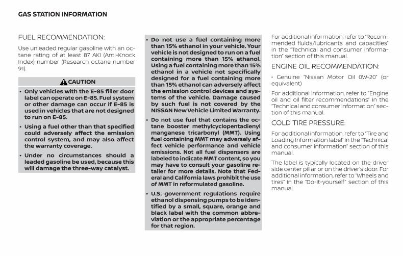
FUEL RECOMMENDATION:Use unleaded regular gasoline with an oc-tane rating of at least 87 AKI (Anti-KnockIndex) number (Research octane number91).
CAUTION∙ Only vehicles with the E-85 filler door
label can operate on E-85. Fuel systemor other damage can occur if E-85 isused in vehicles that are not designedto run on E-85.
∙ Using a fuel other than that specifiedcould adversely affect the emissioncontrol system, and may also affectthe warranty coverage.
∙ Under no circumstances should aleaded gasoline be used, because thiswill damage the three-way catalyst.
∙ Do not use a fuel containing morethan 15% ethanol in your vehicle. Yourvehicle is not designed to run on a fuelcontaining more than 15% ethanol.Using a fuel containing more than 15%ethanol in a vehicle not specificallydesigned for a fuel containing morethan 15% ethanol can adversely affectthe emission control devices and sys-tems of the vehicle. Damage causedby such fuel is not covered by theNISSAN New Vehicle Limited Warranty.
∙ Do not use fuel that contains the oc-tane booster methylcyclopentadienylmanganese tricarbonyl (MMT). Usingfuel containing MMT may adversely af-fect vehicle performance and vehicleemissions. Not all fuel dispensers arelabeled to indicate MMT content, so youmay have to consult your gasoline re-tailer for more details. Note that Fed-eral and California laws prohibit the useof MMT in reformulated gasoline.
∙ U.S. government regulations requireethanol dispensing pumps to be iden-tified by a small, square, orange andblack label with the common abbre-viation or the appropriate percentagefor that region.
For additional information, refer to “Recom-mended fluids/lubricants and capacities”in the “Technical and consumer informa-tion” section of this manual.
ENGINE OIL RECOMMENDATION:• Genuine “Nissan Motor Oil 0W-20” (orequivalent)
For additional information, refer to “Engineoil and oil filter recommendations” in the“Technical and consumer information” sec-tion of this manual.
COLD TIRE PRESSURE:For additional information, refer to “Tire andLoading Information label” in the “Technicaland consumer information” section of thismanual.
The label is typically located on the driverside center pillar or on the driver’s door. Foradditional information, refer to “Wheels andtires” in the “Do-it-yourself ” section of thismanual.
GAS STATION INFORMATION
RECOMMENDED NEW VEHICLEBREAK-IN PROCEDURE:During the first 1,200 miles (2,000 km) ofvehicle use, follow the break-in procedurerecommendations for the future reliabilityand economy of your new vehicle. For ad-ditional information, refer to “Break-inschedule” in the “Starting and driving” sec-tion of this manual. Failure to follow theserecommendations may result in vehicledamage or shortened engine life.


HT32-D
Printing : July 2018Publication No.:
Printed in the U.S.A.OM19EA HT32U0