company · 2019-01-18 · 3 company tecnomatic italia is a young and dynamic company that produces...
TRANSCRIPT


3
COMP
ANY
Tecnomatic Italia is a young and dynamic company that produces cam switches.In addition to the production of the range of standard cam switches from 12A to 63A we produce special scheme products based on customer specifications, providing a complete service.Our headquarters is located in Treviso in the heart of the productive Veneto region. Inside, we have a modern laboratory where the switches are assembled, and through accurate test tests, we guarantee the quality and reliability of each single product.The produced product is subjected to periodic and constant visits by control commissions for the renewal of certifications, so we are able to always guarantee the highest standards for compliance with all safety regulations for the use of our products.Our product is used in various industrial sectors, starting from electrical distribution boards, food industry machines, woodworking machines, pressure washers, electric motors, welding machines and many others.To offer a complete service to our customers, we have a wide range of complementary items such as: buttons, contactors, thermal relays, control boxes, pilot lights, craine control boxes, selectors disconnectors that, together with our switch and switch, constitute a complete package high technology.We strongly believe in our products, the result of professionalism and quality, our goal is to constantly renew ourselves through the use of new materials and new types of design, in order to make our cam switches, always in the vanguard and technologically advanced. Moreover, thanks to the quality of our product, the service offered and the flexibility and speed of deliveries, we want to satisfy all the companies even the most demanding.Therefore, in a world economy where the market requires greater flexibility and professionalism, even through innovative, reliable and quality solutions, we can guarantee that we are always clear on our mission, so much so that we also want to be a point of reference in the future. in the field of industrial automation components, promoting our brand to be recognized all over the world as a product entirelyMade in Italy.

4
GENE
RAL I
NDEX
General Index
HD SERIES CAM SWITCH .................................................................................5HF SERIES CAM SWITCH .................................................................................6BODIES CODIFICATION MAP .............................................................................7ELECTRICAL SCHEMES OFF – ON SWITCHES ....................................................8ELECTRICAL SCHEMES CHANGE OVER SWITCHES ...........................................9ELECTRICAL SCHEMES STEP SWITCHES ..........................................................10ELECTRICAL SCHEMES MOTOR SWIRCHES ......................................................11ELECTRICAL SCHEMES MOTOR SWITCHES.......................................................12ELECTRICAL SCHEMES AMMETER AND VOLTMETER SWITCHES .......................14ACTUATOR CODIFICATION ................................................................................15ACCESSORIES .................................................................................................16DIMENSIONS PANEL MOUNTING .....................................................................17DIMENSIONS BASE MOUNTING .......................................................................19DIMENSIONS DIN MOUNTING ..........................................................................20PANEL MOUNTING VERSION LIST ....................................................................21PANEL MOUNTING VERSION LIST ....................................................................22BASE MOUNTING VERSION LIST ......................................................................22DIN MOUNTING VERSION LIST ........................................................................22SPECIFICATIONS .............................................................................................23HD TECHINICAL DATA ......................................................................................24HF TECHINCAL DATA .......................................................................................26PUSH BUTTON ...............................................................................................28SELECTORS ....................................................................................................31EMERGENCY STOP Ø 22 ..................................................................................32JOYSTICK ........................................................................................................33CONTACT BLOCK .............................................................................................34ACCESSORIES .................................................................................................35ILLUMINATED ROCKER SWITCH AND PILOT LIGHT ...........................................36CONTROL BOXES .............................................................................................37CRAINE CONTROL BOXES ................................................................................38HN SERIES CONTACTORS ................................................................................40JA25 SERIES THERMAL RELAY ........................................................................42

5
• Class self-extinguishing thermoplastic body
• M3 metric screw fixing
• Differents metal control shaft
• IP20 degree of protection contacts
• Quick connection terminals Faston straight/45°/90°
• Different types and size of fixing screws can be supplied on request
• Gold contacts for low voltage signal control
HD SERIES CAM SWITCH
• HD 12A• HD 16A• HD 20A
DESC
RIPT
ION
6
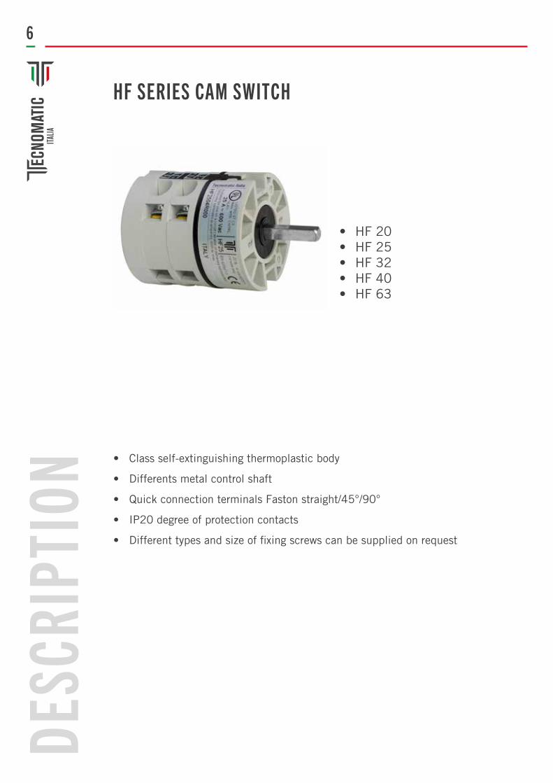
• Class self-extinguishing thermoplastic body
• Differents metal control shaft
• Quick connection terminals Faston straight/45°/90°
• IP20 degree of protection contacts
• Different types and size of fixing screws can be supplied on request
HF SERIES CAM SWITCH
• HF 20• HF 25• HF 32• HF 40• HF 63
DESC
RIPT
ION

7
BODY CODIFICATION MAP
Off-On switch 1 poleOff-On switch 2 polesOff-On switch 3 polesOff-On switch 4 polesChange over switch 1 poleStep switch 1-2 without zero 1 poleChange over switch 2 poleStep switch 1-2 without zero 2 polesChange over switch 3 poleStep switch 1-2 without zero 3 polesReversing switch 3 polesChanging switch dahlander poleStar delta starter switchReversing switch pole changingStar delta change over switch with reverseVoltmeter switch phase/neutralVoltmeter switch phase/phaseVoltmeter switch phase/phase for 2 circuitsVoltmeter switch phase/phase + phase neutralAmmeter switch 1 pole for 3 current transformersAmmeter switch 2 poles for 3 current transformersOff – on switch with spring returnStarter switch single phase with aux. phaseReversing starter switch single phase + aux. phaseOff-on Switch 1 pole with spring returnReversing switch 3 poles with spring return to zeroChange over switch 4 poles Step switch 1-2 without zero 4 polesChange over switch 1 pole with separate entryStep switch 1-2 without zero 1 pole with separated entryChange over switch 2 poles with separate entryStep switch 1-2 without zero 2 poles with separated entryChange over switch 3 poles with separate entryStep switch 1-2 without zero 3 poles with separated entryChange over switch 4 poles with separate entryStep switch 1-2 without zero 4 poles with separated entryOff on switch 4 polesReversing switch single phase with centrifugal cut – out
0102030405
05D06
06D07
07D0809101112151617182225293132353640
40D41
41D42
42D43
43D44
44D4546
1612 20
20 25 4032 63
SERIES MOUNTING TYPE ACTUATOR CODIFICATION
AMPEREHD
Seepag. 21
HF
F/R Panel mounting
Base mounting
Mounting
T
DIN
HD 12 03 R 812
STANDARD SCHEMES
8
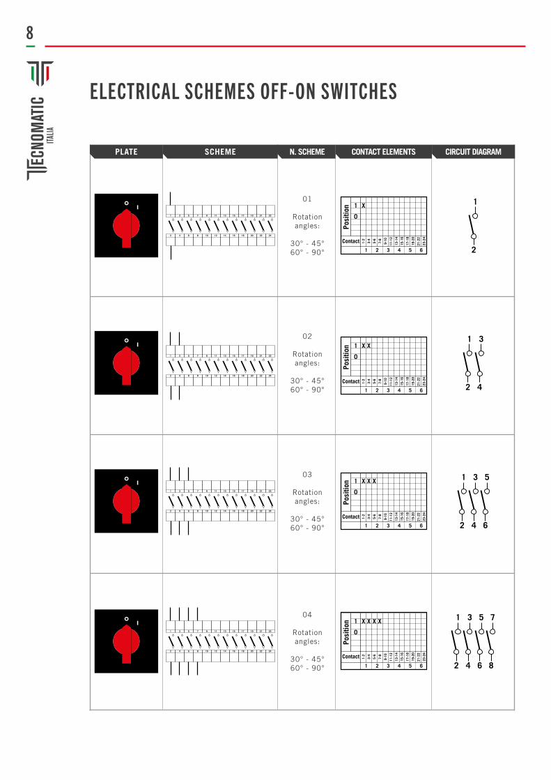
ELECTRICAL SCHEMES OFF-ON SWITCHES
01
Rotation angles:
30° - 45°60° - 90°
1
2
02
Rotation angles:
30° - 45°60° - 90°
1
2
3
4
03
Rotation angles:
30° - 45°60° - 90°
1
2
3
4
5
6
04
Rotation angles:
30° - 45°60° - 90°
1
2
3
4
5
6
7
8
1 3 5 7 9 11 13 15 17 19 21 23
2 4 6 8 10 12 14 16 18 20 22 24
1 3 5 7 9 11 13 15 17 19 21 23
2 4 6 8 10 12 14 16 18 20 22 24
1 3 5 7 9 11 13 15 17 19 21 23
2 4 6 8 10 12 14 16 18 20 22 24
1 3 5 7 9 11 13 15 17 19 21 23
2 4 6 8 10 12 14 16 18 20 22 24
PLATE SCHEME CONTACT ELEMENTS CIRCUIT DIAGRAMN. SCHEME
Posi
tion
Contact
Posi
tion
Contact
Posi
tion
Contact
Posi
tion
Contact
9
PLATE SCHEME CONTACT ELEMENTS CIRCUIT DIAGRAMN. SCHEME
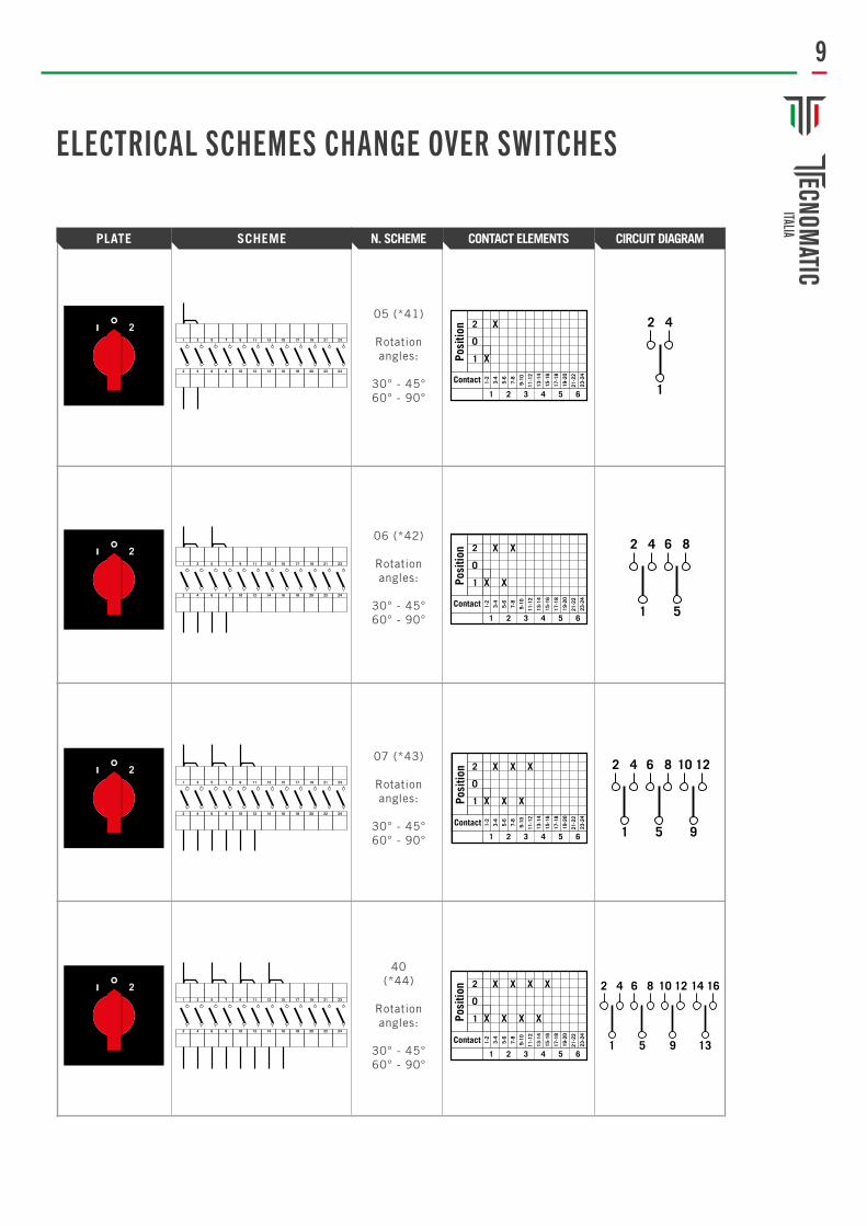
ELECTRICAL SCHEMES CHANGE OVER SWITCHES
07 (*43)
Rotation angles:
30° - 45°60° - 90°
2 4
1
6 8
5
10 12
9
40(*44)
Rotation angles:
30° - 45°60° - 90°
05 (*41)
Rotation angles:
30° - 45°60° - 90°
2 4
1
06 (*42)
Rotation angles:
30° - 45°60° - 90°
2 4
1
6 8
5
2
2
2
2
1 3 5 7 9 11 13 15 17 19 21 23
2 4 6 8 10 12 14 16 18 20 22 24
1 3 5 7 9 11 13 15 17 19 21 23
2 4 6 8 10 12 14 16 18 20 22 24
1 3 5 7 9 11 13 15 17 19 21 23
2 4 6 8 10 12 14 16 18 20 22 24
1 3 5 7 9 11 13 15 17 19 21 23
2 4 6 8 10 12 14 16 18 20 22 24
Posi
tion
Contact
Posi
tion
Contact
Posi
tion
Contact
Posi
tion
Contact

10
ELECTRICAL SCHEMES STEP SWITCHES
06D (*42D)
Rotation angles:
60°
2 4
1
6 8
5
05D (*41D)
Rotation angles:
60°
2 4
1
07D (*43D)
Rotation angles:
60°
2 4
1
6 8
5
10 12
9
40D (*44D)
Rotation angles:
60°
2 4
1
6 8
5
10 12
9
14 16
13
2
2
2
2
1 3 5 7 9 11 13 15 17 19 21 23
2 4 6 8 10 12 14 16 18 20 22 24
1 3 5 7 9 11 13 15 17 19 21 23
2 4 6 8 10 12 14 16 18 20 22 24
1 3 5 7 9 11 13 15 17 19 21 23
2 4 6 8 10 12 14 16 18 20 22 24
1 3 5 7 9 11 13 15 17 19 21 23
2 4 6 8 10 12 14 16 18 20 22 24
PLATE SCHEME CONTACT ELEMENTS CIRCUIT DIAGRAMN. SCHEME
Posi
tion
Contact
Posi
tion
Contact
Posi
tion
Contact
Posi
tion
Contact

11
09
Rotation angles:
30° - 45°60° - 90°
10
Rotation angles:
30° - 45°60° - 90°
11
Rotation angles:
30° - 45°
ELECTRICAL SCHEMES MOTOR SWITCHES
08
Rotation angles:
30° - 45°60° - 90°
2
2
1 3 5 7 9 11 13 15 17 19 21 23
2 4 6 8 10 12 14 16 18 20 22 24
TW V U
S R
1 3 5 7 9 11 13 15 17 19 21 23
2 4 6 8 10 12 14 16 18 20 22 24
1 3 5 7 9 11 13 15 17 19 21 23
2 4 6 8 10 12 14 16 18 20 22 24
1 3 5 7 9 11 13 15 17 19 21 23
2 4 6 8 10 12 14 16 18 20 22 24
PLATE SCHEME CONTACT ELEMENTS CIRCUIT DIAGRAMN. SCHEME
Posi
tion
Contact
Posi
tion
Contact
Posi
tion
Contact
Posi
tion
Contact

12
12
Rotation angles:
30° - 45°60° - 90°
31
Rotation angles:
30°
32
Rotation angles:
30°
35
Rotation angles:
30°
1
2
ELECTRICAL SCHEMES MOTOR SWITCHES
1 3 5 7 9 11 13 15 17 19 21 23
2 4 6 8 10 12 14 16 18 20 22 24
1 3 5 7 9 11 13 15 17 19 21 23
2 4 6 8 10 12 14 16 18 20 22 24
1 3 5 7 9 11 13 15 17 19 21 23
2 4 6 8 10 12 14 16 18 20 22 24
1 3 5 7 9 11 13 15 17 19 21 23
2 4 6 8 10 12 14 16 18 20 22 24
PLATE SCHEME CONTACT ELEMENTS CIRCUIT DIAGRAMN. SCHEME
Posi
tion
Contact
Posi
tion
Contact
Posi
tion
Contact
Posi
tion
Contact

13
ELECTRICAL SCHEMES MOTOR SWITCHES
36
Rotation angles:
30° - 45°60° - 90°
45
Rotation angles:
30° - 45°60° - 90°
1
2
3
4
5
6
7
8
46
Rotation angles:
30° - 45°60° - 90°
29
Rotation angles:
30°
2
1 3 5 7 9 11 13 15 17 19 21 23
2 4 6 8 10 12 14 16 18 20 22 24
2
1 3 5 7 9 11 13 15 17 19 21 23
2 4 6 8 10 12 14 16 18 20 22 24
1 3 5 7 9 11 13 15 17 19 21 23
2 4 6 8 10 12 14 16 18 20 22 24
1 3 5 7 9 11 13 15 17 19 21 23
2 4 6 8 10 12 14 16 18 20 22 24
PLATE SCHEME CONTACT ELEMENTS CIRCUIT DIAGRAMN. SCHEME
Contactor
CamSwitches
ControlCoil
Posi
tion
Contact
Posi
tion
Contact
Posi
tion
Contact
Posi
tion
Contact

14
ELECTRICAL SCHEMES AMMETER AND VOLTMETER SWITCHES
15
Rotation angles:
30° - 45°60° - 90°
16
Rotation angles:
30° - 45°60° - 90°
18
Rotation angles:
30° - 45°60° - 90°
22
Rotation angles:
30° - 45°60° - 90°
25
Rotation angles:
30°
General notes: all the wiring diagrams can be realized with angle of rotation30° - 45° - 60°-90°. Normally all the switches are made with a 30 °, except for the amperometric and voltmetric switches (45 ° angle of rotation) and the star-angle starters (60 ° angle of rotation).
L1
L2
L3
L1
L2
L3
L1L2L1N
L2N
L3N
L2L3
L3L1
1 3 5 7 9 11 13 15 17 19 21 23
2 4 6 8 10 12 14 16 18 20 22 24
1 3 5 7 9 11 13 15 17 19 21 23
2 4 6 8 10 12 14 16 18 20 22 24
1 3 5 7 9 11 13 15 17 19 21 23
2 4 6 8 10 12 14 16 18 20 22 24
1 3 5 7 9 11 13 15 17 19 21 23
2 4 6 8 10 12 14 16 18 20 22 24
L1L2
L2L3
L3L1
1 3 5 7 9 11 13 15 17 19 21 23
2 4 6 8 10 12 14 16 18 20 22 24
PLATE SCHEME CONTACT ELEMENTS CIRCUIT DIAGRAMN. SCHEME
Posi
tion
Contact
Posi
tion
Contact
Posi
tion
Contact
Posi
tion
Contact
Posi
tion
Contact

15
Base mounting
Plate
F1BPadlockable plate 52x52mm
F1Plate 52x52mm
R9Plate ø60mm
F3Padlockable plate 76x76mm
F2Plate 76x76mm
GREY DIN PLATE 45x62mm
PROTECTION PLATEø68mm
PADLOCKABLE PLATEø68mm
F1NPlate 48x48mm
R8Plate ø50mm
Panel mounting
52x52mm
ø50mm
ø60mm
48x48mm
76x76mm
52x52mm
76x76mm
ESECUZIONE DIMENSIONE COLORI
PROTECTION CLASS IP65
MOUNTING TYPE

16
FASTON FASTON 45° FASTON 90°
PADLOCKABLE KNOBØ50mm
PADLOCKABLE KNOB Ø65mm
EXTENSION UNIT
SUPPORT DIN RAIL MOUNTING
KNOBØ34mm Lenght 50mm
SOFT BOOT PROTECTION
SQUARE LONG DOOR LOCK DIFFERENT LEIGHTS
HF 40/63° SERIES CONTACT PROTECTION
HD SERIES CONTACT PROTECTION
HF SERIES CONTACT PROTECTION
BOOT PROTECTION
PLATE PROTECTION IP 65
ACCESSORIES
BUTTON KNOBØ26mm Lenght 40mm

17
SERIE PLATE SIDE BASE MOUNTING QUOTE +/- 0,05mm
REAR PANEL MOUNTING
HD 12-16AR8R9
HF 20-32AR8R9
HD 12-16AF1F2
*The L dimension refers to the switches with a single element, for each addi-tional element add the measure E
TypeHD12R8HD16R8HD12R9HD16R9
D43434343
L*38,538,538,538,5
E9,59,59,59,5
S22,522,525,525,5
TypeHF20R8HF20R9HF25R8HF25R9HF32R8HF32R9
TypeHF20F1HF20F2HF25F1HF25F2HF32F1HF32F2
TypeHD12F1HD12F2HD16F1HD16F2
D49,549,5 49,5 49,549,549,5
D43434343
L*43,543,543,543,543,543,5
L*38,538,538,538,5
E121212121212
E9,59,59,59,5
S22,525,522,525,522,525,5
S26302630
ø50 - 60mm
ø50 - 60mm
52x52 76x76mm
HF 20-32AF1F2
D49,549,549,549,549,549,5
L*43,543,543,543,543,543,5
E121212121212
S263026302630
52x52 76x76mm
HD 12-16AR6
TypeHD12R6HD16R6
D4343
L*38,538,5
E9,59,5
S28,228,2
Ø68mm

18
*The L dimension refers to the switches with a single element, for each additional element add the measure E
REAR PANEL MOUNTING
HF 20-32AR6
HD 12-16AF3
HF 20-32AF3
TypeHF20R6HF25R6HF32R6
TypeHD12F3HD16F3
TypeHD12T1HD12T1BHD12T1CHD12T2HD12T3HD16T1HD16T1BHD16T1CHD16T2HD16T3
TypeHF20F3HF25F3HF32F3
D4343
D49,549,5 49,5
D49,549,549,5
L*38,538,5
L*43,543,543,5
L*43,543,543,5
E9,59,5
E121212
E121212
S32,532,5
S28,228,228,2
S32,532,532,5
55x55 76x76mm
55x55 76x76mm
55x55 76x76mm
HD 12-16AT1T3
D69,569,569,569,569,569,569,569,569,569,5
L*38,538,538,538,538,538,538,538,538,538,5
E9,59,59,59,59,59,59,59,59,59,5
S85767690
90,585767690
90,5
Ø68mm
SERIE PLATE SIDE BASE MOUNTING QUOTE +/- 0,05mm

19
*The L dimension refers to the switches with a single element, for each additional element add the measure E
BASE MOUNTING
TypeHF20T1HF20T1BHF20T1CHF20T2HF20T3HF25T1HF25T1BHF25T1CHF25T2HF25T3HF32T1HF32T1BHF32T1CHF32T2HF32T3
D69,569,569,569,569,569,569,569,569,569,569,569,569,569,569,5
L*43,543,543,543,543,543,543,543,543,543,543,543,543,543,543,5
E121212121212121212121212121212
S85767690
90,585767690
90,585767690
90,5
HF 20-32AT1T3
HF 40-63AT1
T1BT1CT2T3
HF40-63AF1-F2-F3
55x55 76x76mm
55x55 76x76mm
52x52 76x76mm
TypeHF40-63F1HF40-63F2HF40-63F3
TypeHF40-63T1HF40-63T1BHF40-63T1CHF40-63T2HF40-63T3
D69,569,569,5
PARALLEL CONNECTIONS
PARALLEL CONNECTIONS
D69,569,569,569,569,5
L*55,555,555,5
L*55,555,555,555,555,5
E242424
E2424242424
S2630
32,5
S85767690
90,5
SERIE PLATE SIDE BASE MOUNTING QUOTE +/- 0,05mm

20
SERIE PLATE SIDE QUOTE +/- 0,05mm
DIN RAIL MOUNTING
HD 12-16ADIN1DIN2
HD12-16TDHF20-32TDHF40-63TD
* The L dimension refers to the three-element switches, for each additional element, add the measure E
** The L dimension refers to the switches with a single element, for each additional element add the measure E
TypeHD12-16TDHF20-32TDHF40-63TD
D565656
L**28,543,543,5
E9,51212
S242424
TypeHD12DHD16D
D5656
L*47,547,5
E9,59,5
S36,536,5
B11,211,2
B11,222,522,5
ø45mm
45x52,5mm

21
REAR PANEL MOUNTINGCOD. DescriptionR811 Black or yellow plastic plate ø50mm red knob ø26mm
R812 Black or yellow plastic plate ø50mm black knob ø26mm
R813 Black or yellow plastic plate ø50mm grey knob ø26mm
R814 Black or yellow plastic plate ø50mm yellow knob ø26mm
R921 Black or yellow plastic plate ø60mm red knob ø34mm
R922 Black or yellow plastic plate ø60mm black knob ø34mm
R923 Black or yellow plastic plate ø60mm grey knob ø34mm
R924 Black or yellow plastic plate ø60mm yellow knob ø34mm
R641 Yellow padlockable plate ø68mm red padlockable knob Ø65mm
R642 Yellow padlockable plate ø68mm black padlockable knob Ø65mm
R643 Yellow padlockable plate ø68mm grey padlockable knob Ø65mm
R7A41 Black padlockable plate ø68mm red padlockable knob Ø65mm
R7A42 Black padlockable plate ø68mm black padlockable knob Ø65mm
R7A43 Black padlockable plate ø68mm grey padlockable knob Ø65mm
R1241 Grey padlockable plate ø68mm red padlockable knob Ø65mm
R1242 Grey padlockable plate ø68mm black padlockable knob Ø65mm
R1243 Grey padlockable plate ø68mm grey padlockable knob Ø65mm
R6A21 Yellow proteced plate ø68mm red knob Ø34mm
R6A22 Yellow proteced plate ø68mm black knob Ø34mm
R6A23 Yellow proteced plate ø68mm grey knob Ø34mm
R721 Black proteced plate ø68mm red knob Ø34mm
R722 Black proteced plate ø68mm black knob Ø34mm
R723 Black proteced plate ø68mm grey knob Ø34mm
R1321 Grey proteced plate ø68mm red knob Ø34mm
R1322 Grey proteced plate ø68mm black knob Ø34mm
R1323 Grey proteced plate ø68mm grey knob Ø34mm
F111 Black plate 52x52mm red knob ø26mm
F112 Black plate 52x52mm black knob ø26mm
F113 Black plate 52x52mm grey knob ø26mm
F114 Black plate 52x52mm yellow knob ø26mm
F1A11 Grey plate 52x52mm red knob ø26mm
F1A12 Grey plate 52x52mm black knob ø26mm
F1A13 Grey plate 52x52mm grey knob ø26mm
F1A14 Grey plate 52x52mm yellow knob ø26mm
F221 Black plate 76x76mm red knob ø34mm
F222 Black plate 76x76mm black knob ø34mm
F223 Black plate 76x76mm grey knob ø34mm
F224 Black plate 76x76mm yellow knob ø34mm
F2A21 Grey plate 76x76mm red knob ø34mm
F2A22 Grey plate 76x76mm black knob ø34mm
F2A23 Grey plate 76x76mm grey knob ø34mm
F2A24 Grey plate 76x76mm yellow knob ø34mm
F341 Yellow padlockable plate 76x76mm red padlockable knob Ø65mm
F342 Yellow padlockable plate 76x76mm black padlockable knob Ø65mm
F343 Yellow padlockable plate 76x76mm grey padlockable knob Ø65mm
F441 Black padlockable plate 76x76mm red padlockable knob Ø65mm
F442 Black padlockable plate 76x76mm black padlockable knob Ø65mm
F443 Black padlockable plate 76x76mm grey padlockable knob Ø65mm

22
DIN1 Grey Din plate with red button
DIN2 Grey Din plate with black button
COD. Description
F1041 Grey padlockable plate 76x76mm red padlockable knob Ø65mm
F1042 Grey padlockable plate 76x76mm black padlockable knob Ø65mm
F1043 Grey padlockable plate 76x76mm grey padlockable knob Ø65mm
F1B51 Yellow padlockable plate 55x55mm red padlockable knob Ø50mm
F1B52 Yellow padlockable plate 55x55mm black padlockable knob Ø50mm
F1B53 Yellow padlockable plate 55x55mm grey padlockable knob Ø50mm
F3A21 Yellow proteced plate 76x76mm red knob Ø34mm
F3A22 Yellow proteced plate 76x76mm black knob Ø34mm
F3A23 Yellow proteced plate 76x76mm grey knob Ø34mm
F521 Black proteced plate 76x76mm red knob Ø34mm
F522 Black proteced plate 76x76mm black knob Ø34mm
F1121 Grey proteced plate 76x76mm red knob Ø34mm
F1122 Grey proteced plate 76x76mm black knob Ø34mm
F1123 Grey proteced plate 76x76mm grey knob Ø34mm
T111 Black plate 52x52mm red knob ø26mm
T112 Black plate 52x52mm black knob ø26mm
T113 Black plate 52x52mm grey knob ø26mm
T221 Black plate 76x76mm red knob ø34mm
T222 Black plate 76x76mm black knob ø34mm
T223 Black plate 76x76mm grey knob ø34mm
T341 Yellow padlockable plate 76x76mm red padlockable knob Ø65mm
T342 Yellow padlockable plate 76x76mm black padlockable knob Ø65mm
T343 Yellow padlockable plate 76x76mm grey padlockable knob Ø65mm
T441 Black padlockable plate 76x76mm red padlockable knob Ø65mm
T442 Black padlockable plate 76x76mm black padlockable knob Ø65mm
T443 Black padlockable plate 76x76mm grey padlockable knob Ø65mm
T1041 Grey padlockable plate 76x76mm red padlockable knob Ø65mm
T1042 Grey padlockable plate 76x76mm black padlockable knob Ø65mm
T1043 Grey padlockable plate 76x76mm grey padlockable knob Ø65mm
T1B51 Yellow padlockable plate 55x55mm red padlockable knob Ø50mm
T1B52 Yellow padlockable plate 55x55mm black padlockable knob Ø50mm
T1B53 Yellow padlockable plate 55x55mm grey padlockable knob Ø50mm
T3A21 Yellow proteced plate 76x76mm red knob Ø34mm
T3A22 Yellow proteced plate 76x76mm black knob Ø34mm
T3A23 Yellow proteced plate 76x76mm grey knob Ø34mm
T521 Black proteced plate 76x76mm red knob Ø34mm
T522 Black proteced plate 76x76mm black knob Ø34mm
T523 Black proteced plate 76x76mm grey knob Ø34mm
T1121 Grey proteced plate 76x76mm red knob Ø34mm
T1122 Grey proteced plate 76x76mm black knob Ø34mm
T1123 Grey proteced plate 76x76mm grey knob Ø34mm
REAR PANEL MOUNTING
BASE MOUNTING
DIN RAILMONTING

23
SPECIFICATIONS
All the appliances are built in compliance with the EN 60947-3 standards
Control motor and three phase load switch
SerieRated
thermal current
Rated insulation
voltage
AC 1AC 21B3x380V
Ui [V]Ith2 [A]
HD12 12 660
660
660
660
660
660
660
HF20 20
HF32 32
HD63 63
HD16 16
HF25
[KW]
7,5
12,5
20
10
1725
AC 2AC 22B3x380V
[KW]
4
9
14
7,5
12
[HP]
5,5
12
19
10
16
AC 3AC 23B3x380V
[KW]
3,5
7,5
5
9,5
[HP]
4,5
10
6,7
13
HF40 40
1. Impossibility of casual contact with live parts (electric finger proof terminals)2. Absence of earth clamp, being all rotating parts insulated from live parts.3. Extreme ease of modification to the initial scheme, given the total modularity..4. Total interchangeability with the most common types on the market.
TECHNICAL FEATURES
CHARACTERISTICS

24
HD TECHNICAL DATA
Rated operating current le: alternate current
RATED OPERATING CURRENT le: direct current
AC-21A Switching resistive loads, including moderate overloads
DC-21A Switching resistive loads, including moderate overloads 50V (1 pole)
DC-22A Switching of mixed resistive and inductive loads, including moderate overloads 30V (1 pole)
Power dissipation for each pole
AC-22A Switching of mixed resistive and inductive loads, including moderate overloads
AC23A Switching of motor loads or other highly inductive loads 1 phase - 2 poles
AC23A Switching of motor loads or other highly inductive loads 3 phases - 3 poles
AC-3 Squirrel cage motors: starting, swtiching off motors during runnin 1 phase - 2 poles
AC-3 Squirrel cage motors: starting, swtiching off motors during running 3 phases - 3 poles
AC-23A Rated breaking capability in (cos ϕ = 0,45)
IEC 947-3 EN 60947-3
Rated insulation voltage
Rated thermal current for open switch
Rated thermal current for enclosed switch
Rated operating voltage
Rated impulse withstand voltage
Rated operation frequency
HD 20HD 16HD 12
A
A
V
K V
A
V
A
Hz
16
16
660
4
400
16
16
50
20
20
660
6
400
20
20
50
400V
110V A/Kw
230V A/Kw
400V
Ui
Uimp
Ithe
Ue
Ith
12
A 12 1610
A 10 128
W 0,3 0,450,3
12
14/1,5
14/3,1
18/2,1
18/4,1
12/1,1
12/2,2
13/4,2
13/7,5
16/5,1
16/9,1
230V A/Kw
400V A/Kw
10/2,5
10/4,2
12/1,1
12/2,5
16/1,5
16/3,5
110V A/Kw
230V A/Kw
10/0,95
10/2,1
10/3,1
10/5,1
12/4,5
10/7,5
230V A/Kw
400V A/Kw
8/2,1
8/3,5
110
110
135
130
230V A/Kw
400V A/Kw
110
110
660
4
400
12
12
50

25
HD TECHNICAL DATA
Short circuit characteristics
UL 508 Characteristics
File File
Rated short time withstand current
General Use
Mechanical characteristics
Connections according to IEC 947 and EN 60947-1
Certifications
Ambient conditions
Mechanical lifetime
Connecting capability with flexible wires
UL - USA
Operating ambient temperature
Connection terminal screw
CE mark- Europe
Connecting capability with solid wires
IMQ - Italia
Storage ambient temperature
Screwing torque
Protection class terminals
Electrical lifetime
Open angles
(120 cicles/hour)
mm2
AC-21
mm2
Contact double breaking
30° - 45° - 60° - 90°
Standard motor load 1 phase - 2 poles
3 phases - 3 polesStandard motor load
With fuses class G
Rated short-circuit make capacity
Rated conditional short-circuit current
HD 20HD 16HD 12
A
A
Hp
Hp
Hp
Hp
Hp
Hp
KA
A
A
300
5
20
16
1,5
0,75
1
3
7,5
1,5
5
7,5
500
10
25
1,5
0,75
lcw 1s
600 Va
Mil. Man.
Min - Max
Type
Type
Mil. Man.
Min - Max
C°
C°
Nm
120 Va
240 Va
200 Va
240 Va
480 Va
600 Va
Icm
500V
300
5
1200 1200 2800
16
12
1,5
2x1,5-2,5
E102112
25-55
M3
Yes
2x1,5-4
No
30-70
0,8
IP20
2x1,5-2,5
E102112
25-55
M3
Yes
2x1,5-4
No
30-70
0,8
IP20
2x2,5-4
No
25-55
M3
Yes
2x2,5-6
No
30-70
0,8
IP20
1
0,5
1,5
5
1
3
5

26
HF TECHNICAL DATA
Rated operating current le: alternate current
RATED OPERATING CURRENT le: direct current
HF 63HF 40HF 32HF 25
V
A
A
W
K V
A
V
A
A
A
Hz
660
400
40
40
660
66 66
400
63
63
Ui
110V A/Kw
230V A/Kw
230V A/Kw
110V A/Kw
230V A/Kw
400V A/Kw
230V A/Kw
400V A/Kw
230V A/Kw
400V A/Kw
400V
400V
Uimp
Ith
Ue
Ith
660660
400400
32
32
25
25
50 5050 50
2520
20 16
0,45 0,85 0,850,45
25/2,220/1,5
30/9,125/7,5
20/1,516/1,1
23/7,518/5,5
220220
32
32
25
25
30/5,525/4,1
27/1522/10,9
25/3,920/3,7
20/10,916/7,5
220220
A
KA
A
A
lcw 1s
Icm
500V
500500
1010
28002800
3225
IEC 947-3 EN 60947-3
Rated insulation voltage
Rated thermal current for open switch
Rated thermal current for enclosed switch
Rated operating voltage
Rated impulse withstand voltage
Rated operation frequency
AC-21A Switching resistive loads, including moderate overloads
AC-22A Switching of mixed resistive and inductive loads, including moderate overloads
AC-23A Rated breaking capability in (cos ϕ = 0,45)
Power dissipation for each pole
DC-21A Switching resistive loads, including moderate overloads 50V (1 pole)
DC-22A Switching of mixed resistive and inductive loads, including moderate overloads 30V (1 pole)
Short circuit characteristics
Rated short time withstand current
With fuses class G
Rated short-circuit make capacity
Rated conditional short-circuit current
AC23A Switching of motor loads or other highly inductive loads 1 phase - 2 poles
AC23A Switching of motor loads or other highly inductive loads 3 phases - 3 poles
AC-3 Squirrel cage motors: starting, swtiching off motors during runnin 1 phase - 2 poles
AC-3 Squirrel cage motors: starting, swtiching off motors during running 3 phases - 3 poles
27
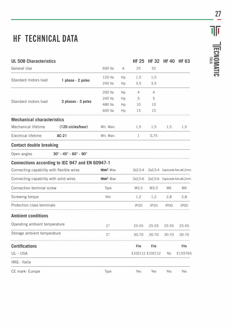
HF TECHNICAL DATA
File File File
HF 63HF 40HF 32HF 25A
Hp
Hp
Hp
Hp
Hp
Hp
32
0,75
1,5
3,5
4
10
5
15
1,5 1,5
600 Va
Mil. Man.
Min - Max
Type
Type
Mil. Man.
Min - Max
C°
C°
Nm
120 Va
240 Va
200 Va
240 Va
480 Va
600 Va
25
1,51,5
2x2,5-4
E102112
25-55
Yes
2x2,5-6
30-70
1,2
IP20
2x2,5-4 Capicorda foro ø6,2mm
Capicorda foro ø6,2mm
E102112
25-55
Yes
2x2,5-6
30-70
1,2
IP20
No E155765
25-55 25-55
M6M3,5 M3,5 M6
Yes Yes
30-70 30-70
2,8 2,8
IP00 IP00
1
1,5
3,5
4
10
5
15
UL 508 CharacteristicsGeneral Use
Standard motors load 1 phase - 2 poles
3 phases - 3 polesStandard motors load
Mechanical characteristics
Connections according to IEC 947 and EN 60947-1
Certifications
Ambient conditions
Mechanical lifetime
Connecting capability with flexible wires
UL - USA
Operating ambient temperature
Connection terminal screw
CE mark- Europe
Connecting capability with solid wires
IMQ - Italia
Storage ambient temperature
Screwing torque
Protection class terminals
Electrical lifetime
Open angles
(120 cicles/hour)
mm2
AC-21
mm2
Contact double breaking
30° - 45° - 60° - 90°

28
Ø 22 PUSH BUTTONS

29 B
100
SERI
ES
ROU
ND
PUSH
BU
TTON
MB1
00D
SERI
ES M
ONOB
LOCK
RO
UN
D PU
SH B
UTT
ON B
200H
SER
IES
PUSH
BU
TTON
HIG
H P
OSIT
ION
BOX / PCS10
BOX / PCS10
BOX / PCS10
COLORS
COLORS
COLORS
COLORS
Ø 22 PUSH BUTTONS
BOX / PCS10
MBS
DØ S
ERIE
S M
ONOB
LOCK
PIL
OT L
IGH
T (L
ED)
24V o 220V

30
DOUBLE HEAD HIGH POSITION WITH SPRING
BOX / PCS8
DOUBLE HEAD HIGH POSITION WITH SPRING
DOUBLE AND FLAT HEAD PUSH BUTTON WITH
EXTENDED STOP
BOX / PCS8
PUSH BUTTONS
DOUBLE AND FLAT HEAD PUSH BUTTON WITH
SPRING
BOX / PCS8
DOBLE AND FLAT HEAD PUSH BUTTON WITH
SPRING
BOX / PCS8
BOX / PCS8
B132
K20H
BB1
32K2
1HB
B132
K20K
YB1
32K2
1KY
B121
B30Y
Y

31B1
00SL
SER
IES
ILLU
MIN
ATED
SE
LECT
OR
B100
A SE
RIES
KEY
SE
LECT
ORB1
00S2
0 SE
RIES
SE
LECT
ORB1
00S
SERI
ES
SELE
CTOR
CP10
0S S
ERIE
S SE
LECT
ORM
B100
S SE
RIES
M
ONOB
LOCK
SEL
ECTO
R
BOX / PCS10
BOX / PCS10
BOX / PCS10
BOX / PCS10
BOX / PCS10
BOX / PCS10
COLORS
SELECTORS
COLORS

32
EMERGENCY STOP Ø 22
Ø 30 CYLINDRICAL HEAD EMERGENCY STOP PUSH
BUTTON
BOX / PCS10
BOX / PCS10
Ø 40 MUSHROOM HEAD EMERGENCY STOP PUSH
BUTTON
BOX / PCS10
Ø 40 MUSHROOM HEAD EMERGENCY STOP
MONOBLOCK BUTTON
BOX / PCS10
Ø 60/90 MUSHROOM HEAD EMERGENCY STOP
PUSH BUTTON
BOX / PCS10
Ø 40 MUSHROOM HEAD EMERGENCY STOP PUSH
BUTTONWITH LIGHTING
B200
E30
B200
EM
B200
ECP
200E
B200
E60

33CP
707D
J
JOYSTICK 2 POSITIONS - 4 POSITIONS
1
2
1
3 4
2
1
2
1
3 4
2

34
B1 S
ERIE
SB2
SER
IES
B3 S
ERIE
SB3
SER
IES
WIT
H
CON
TACT
BLO
CK F
OR
ILLU
MIN
ATIO
N
BOX / PCS20
BOX / PCS20
BOX / PCS20
BOX / PCS20
CONTACT BLOCK
3 4
1 2
X1 X2
X1 2

35BE
BBE
BK20
BEP6
0BE
P90
BOX / PCS20
BOX / PCS20
BOX / PCS20
BOX / PCS20
BOX / PCS20
SILICON COVER FOR SINGLE
BUTTON
SILICON COVER FOR DOUBLE
BUTTON
EMERGENCY PROTECTIVE
COVER
PLATE Ø 60 EMERGENCY
STOP
PLATE Ø 90 EMERGENCY
STOP
ACCESSORIES

36
ILLUMINATED ROCKER SWITCH – PILOT LIGHTA1
4BK1
1A1
2W1K
11S1
00S1
02S1
05
BOX / PCS 10
BOX / PCS 10
BOX / PCS 10
BOX / PCS 10
BOX / PCS 10
COLORS
COLORS
COLORS
COLORS
COLORS

37
CONTROL BOXES
CON
TROL
BOX
E
CONTROL BOX WITH DIFFERENT PUSH BUTTONS
AND CONTACT BLOCK
CON
TROL
BOX
E W
ITH
PU
SH
BUTT
ON B
100
COLORS
CON
TROL
BOX
E W
ITH
EM
ERGE
NCY
ST
OP P
USH
BU
TTON
COLORS
COLORS
EMERGENCY STOP PUSH BUTTONØ30 Ø40

38
CRAINE CONTROL BOXES
General specification
OperatingTemperature: min./max °C -5 / +85Mechanical Life (Operating Frequency): 1.000.000 operations min. Withoud load 3000 operations / hourElecrical Life (Operating Frequency): 100.000 operations min. At full load 1200 operations /hour PV Block Tightening Torque: PV 0.6-0.8 Nm. PV Block Connection Profile: 1x0.5mm2 Wire Profile: 2x2.5mm2Cable Dimensions: Φ8-φ17 Proection Degree: IP65 Technical Information: PV3E30B4Standards: TS EN 60947 5-1In Contact Blocks: VDE 0660 UL508

39

40
HN SERIES CONTACTORS

41
CODECONTACT DIAGRAM
AUXILIARY CONTACTS
RATED THERMAL CURRENT
RATED CURRENT IN AC 3 380V
CONTROLLABLE POWERS OF THREE PHASE MOTORS
CAT. AC2-AC3 220-240V 380-415V 660V
HN910N
HN1710N
HN33N
HN1310N
HN2510N
HN46N
HN75N
HN901N
HN1701N
HN40N
HN65N
HN1301N
HN2501N
HN55N
HN90N
1NO
1NO
1NO
1NO
-
-
-
1NC
1NC
1NC
1NC
-
-
2NO + 2NC
2NO + 2NC
20 A 9 A
30 A 17 A
20 A 13 A
30 A 25 A
45 A 33 A
60 A 46 A
100 A 75 A
45 A 40 A
80 A 65 A
65 A 55 A
110 A 90 A
2.2 kW
3.2 kW
4 kW
6 kW
7.5 kW
15 kW
18.5 kW
11 kW
17 kW
22 kW
26 kW
4 kW
6 `kW
7.5 kW
11 kW
15 kW
22 kW
35 kW
22 kW
30 kW
37 kW
45 kW
4.5 kW
6.5 kW
8.5 kW
12.5 kW
18.5 kW
25 kW
45 kW
30 kW
33 kW
55 kW
67 kW

42
JA25 SERIES THERMAL RELAYJA
25A
CIRCUIT DIAGRAM: JA SERIES THERMAL RELAY SELECTION TABLE
General Specifications
Operating Temperature: min./max -5/+40°CMechanical Life: ≥100.000 (600 op/hour) Electrical Life: ≥100.000 (600 op/hour) Cable Tightening Torque: 1.8 NmWire Profile: 1,5 mm² - 2,5 mm²Standards: TS EN 60947 4-1Range of use: AC 3Insulation Voltage: Ui 690VFrequency: f 50-60HzOperating Current: le 25AStroke resistance voltage: Uimp 6 kV Short circuit breaking capacity: Ics 50 kADielectric Strength (For 1 min.): 1890V ACThermal Current Range: 0.15-0.25 A
JA25A 0.15 - 0.25 JA25B 0.22 - 0.33 JA25C 0.30 - 0.45 JA25D 0.42 - 0.63 JA25E 0.60 - 0.90 JA25F 0.85 - 1.27 JA25G 1.20 - 1.75 JA25H 1.70 - 2.60
JA25I 2.50 - 3.70 JA25L 3.60 - 5.40 JA25M 5.30 - 7.50 JA25N 7.30 - 10.2 JA250 10.0 -15.0 JA25P 13.5 - 20.0 JA25Q 18.0 - 26.0


44
NOTE
S

45
NOTE
S

46
NOTE
S

47
NOTE
S

Progetto grafico ed impaginazioneMida Computers s.a.s.
Via Piave, 1/D - 31050 Ponzano V.to (TV)
StampaTipografia Marca Print