contents€¦ · · 2018-02-04contents chapter page 1. press tool 1 ... lancing. (ii) bending (a)...
TRANSCRIPT

CONTENTS CHAPTER PAGE
1. PRESS TOOL 1-9
2. JIGS AND FIXTURE 1-7
3. INSTALLATION & TESTING OF MACHINE TOOLS 1-13
4. SPECIAL CASTING AND POWER METALLURGY 1-12
5. NON CONVENTIONAL MACHINING PROCESS 1-13

CHAPTER-1 PRESS TOOL
The press is a metal forming machine tool designed to shape or cut metal by applying
Mechanical force or pressure.
The metal is formed to be desired shape without removal of chips.
The presses are exclusively intended for mass production work & they represents the
fastest and most efficient way to form a sheet metal into finished products.
TYPES OF PRESSES:-
The classifications of different types of presses are given below:-
(i) Classification based on source or power:-
(a) Hand press or ball press / fly press.
(b) Power press / power hammer.
(i) Classification based on design of frame.
(a) Gap
(b) Inclinable
(c) Adjustable
(d) Horn
(e) Start side
(f) Pillar
FLY PRESS:-
- The Fly press or ball press is the most simple of all presses & is operated by hand.
- The frame of the machine is a rigid ‘c’ shaped casting which is subjected to the severe
thrust exerted by a ram.
- The typical shape of the frame leaves the front open which facilitates the feeding of the
sheet metal below the ram from the side of the machine.

- The screw of the press operates in a nut, which is incorporated in the top end of the
frame.
- The two heavy cast iron balls are mounted at the two ends of the ram which is bolted to
the screw, so that when the handle is turned it causes the screw to rotate within the
nut.
- The connecting arrangement between the screw & the ram is such that when the screw
is rotated, the ram only slides up and down within the guide.
- The sheet metal to be formed is placed between the punch and die.
- The press is operated by a sharp, practical revolution of the arm by pulling the handle &
the kinetic energy is stored upon the two heavy balls mounted on the arm.
- As the ram is forced downward, the resistance offered by the plate against deformation
is overcome by the tremendous thrust exerted by the punch on the plate at the expense
of the stored to the desired shape.
POWER PRESS:-
- The Constructional, power press is similar to fly press the only difference is the ram
instead of driven by hand is driven by power.

- The power press may be designated as mechanical or hydraulic according to the type of
working merchandisable use to transmit power is to ram.
- In a mechanical press the rotary motion offered from an electric motor is converted into
reciprocating moment of the ram by using different mechanical uses.
- In hydraulic press the fluid under high press high pumped is one site of the piston and
then the other in a hydraulic cylinder to drive the reciprocating moment.
- In above fig in the power press is driven by cranks & connecting rod
mechanism the working of the press is similar to that of a hand press the punch is fitted
to end of Ram & the die attached to the bolster plate. The flywheel is mounted the end
of the crank shaft stores of the energy for maintaining Construct downward speed
other ram when the sheet metal is pressed is to punch into to the die.
POWER PRESS PARTS:-
The different parts of power press are:-
(1) Base
(2) Frame
(3) Bolster Plate

(4) Ram or slide
(5) Pitman
(6) Crank Shaft or eccentric
(7) Fly wheel
(8) Clutch
(9) Brake
Base:-
The base is the supporting member of the press and provides arrangement for fitting
and clamping the frame in an inclined press.
Frame:-
All presses except the straight side type have “c” shaped frame to take up the vertical
thrust of the ram.
Bolster Plate:-
The bolster plate is afloat fitted on the base or supporting the die block and other
accessories of the press.
Ram:-
The Ram is the reciprocating member of the press that slides within the press and
guides and supports the punch at bottom end.
Pitman:-
The pitman is the connecting rod in a crank or eccentric driven press, the position of
stoke of the ram can be changed by altering the length of the connecting rod.

Crank eccentric or other driving Mechanism:-
The rotary movement or the motors converted into the reciprocating movement of the
ram by crank and connecting rod eccentric and connecting rod, eccentric and connecting rod or
many other mechanisms which are described in figure.
Fly wheel:-
The flywheel is mounted at the end of the driving shaft and is connected to it through a
clutch. The energy is stored up in the flywheel during die periods and it is expended to maintain
the constant speed of the ram when the punch is pressed into the work. The fly wheel is
directly coupled with the electric motor.
Clutch:-
The clutch is used for connecting rod disconnecting the driving shaft with the fly wheel
when it is necessary to start or stop the movement of the ram.
Brakes:-
The brakes are used to stop the movement of the driving shaft, immediately after it is
disconnected from the flywheel.
METHODS OF PUNCHES SUPPORT:-
The punches are usually held in steel punch plates of the punch holder which is again
clamped to the lower end of the ram. The various methods of securing punches is punch plates
are illustrated in fig.

View A :-
The punch is forced in the punch plate and the top end of the punch is flattened to fit in
the countersunk recess.
View B:-
The punch is clamped in the punch plate by a set screw and is located by a slot cut in the
punch plate.
View C:-
The shank end of the punch is forced in the punch plate and then the top end of the
punch is flattened to fit in the countersunk recess.
View D:-
The punch is secured to the plate by grub screws.

View E:-
The flange end of the punch is secured to the plate by means of set screws.
View F:-
The punch is secured to the plate of set screw and is located by a dowel pln.
View G:-
The punch is introduced through the back of the plate and fits into the recess; it is then
clamped to the plate by set screw.
View H:-
The punch is secured by a set screw and is located by two dowel plans.
View I:-
The flange end of the punch is secured to the plate by set screws from the punch end.
Types of Dies and Operations:-
Classification based on operations performed:-
(i) Shearing :-
(a) Piercing
(b) Punching
(c) Perforating
(d) Blanking
(e) Cutting off

(f) Parting
(g) Notching
(h) Slitting
(i) Lancing.
(ii) Bending
(a) Angle bending
(b) Curling
(c) Forming
(d) Plunging
(iii) Drawing
(a) Cupping
(iv) Squeezing
(a) Coining
(b) Embossing
(c) Flattening or plainshing.
2. CLASSIFICATION BASED ON CONSTRUCTION:-
(a) Simple
(b) Follow or progressive
(c) Compound

SIMPLE DIE:-
- In a simple die only one operation is performed at each stroke of the ram. All the dies
which are described before are simple dies.
FOLLOW OR PROGRESSIVE DIE:-
- In a progressive die two or more operations are performed simultaneously at a single
stroke of the press by mounting separate sets of dies and punches at two or more
different stations.
- The metal is progressed from one station to the other till the complete part obtained.
The progressive punching and the blanking die is illustrated in fig.

COMPOUND DIE:-
- In a compound die two or more cutting operations are accomplished at one station of
the press in every stroke of the ram.
- The blanking die and the piercing punch and bolted to the ram. The spring loaded
stripper plate is housed within the blanking die. The lower die, body has cutting edges
both on its outward and inward surfaces. The outside cutting edges operate as a die for
the piercing punch.
- The sheet metal is place on the lower the block and as the ram descends, the plate is
first blanked and then pierced by the successive dies sets.
ADVANTAGES & DISADVANTAGES OF DIES & PUNCHES:-
ADVANTAGES:-
- Requires minimal space in the press.
- Leaves all burrs in one direction.
- Superior accuracy between holes & trim edges.
- More economical to build than a progressive die.
- Die casting dies retain their accuracy for a very long time.
- High surface finish is obtained& often no further finishing is required.
DISADVANTAGES:-
- The limited space which ends to leave die components this & weak. This contracts the
loads shock on punches & matrixes resulting in tooling failures.

- All metals & alloys cannot be cat.
- The cost of M/C &, dies & other equipment used is high.
- Not economical for small quality production.
- Heavy casting cannot be cast.
- Special precautions cannot be cost.
- Special precautions are necessary for evacuation of air from die cavity otherwise cause
porosity.
CHAPTER-2 JIGS AND FIXTURE
JIG:-
- A Jig may be defined as a device which holds and locates a work piece and guides
and controls one or more cutting tools.
- The holding of the work & guiding of the holes are such that they are located in two
positions relative to each other.
(JIG)
FIXTURE:-
- A fixture may be defined as a device which holds & locates a workpiece during an
inspection or for a manufacturing operation.
- The fixture does not guide the tool.

Difference between Jig & Fixture:-
- A fixture holds & position the work doesn’t guide the tool, where as a jig holds,
locates and as well as guide the tool.
- The fixtures are generally heavier in construction & are bolted rigidly on the machine
table where as the Jigs are made lighter for quicker handling & clamping with the
table is often necessary.
- The fixtures are employed for holding work in moiling grinding planning or turning
operations where are the jigs are used for holding the work is guiding the tool
particularly is drilling reaming or tapping operations.
Advantage of using of Jig & Fixture:-
- To reduce the cost of production as their use eliminates the laying out of work and
setting up or tools.
- To increase the production.
- To assure high accuracy of the parts.
- To provide for interchange ability.
- To enable heavy and complex- shaped parts to be machined by being hold rigidly to
a machine.
- Reduce quality control expenses.

- Increased versatility of machine tool.
- Less skilled labour.
- Saving labour.
- Their use partially automates the m/c tool there by lowering the rate of accidents.
PRINCIPLE OF LOCATIONS:-
- The location refers to the establishment of a desire relationship between the
workpiece & the jig or fixture. Correct location influences the accuracy of the
finished product.
- The jig & the fixtures are so designed that all possible movements of the
components must be restricted.
- The determination of the locating points & clamping of the work piece serve to
restrict the movements of the components in any direction, while setting it at the
correct position relative to the jig.
- The locating points are determined by fast finding out the possible degrees of
freedom of the work piece, which are then restrained by suitable arrangement
which served as locations.
- In order to study the complete location of the workpiece within a jig and fixture let
us consider the work pieces in the above space.

- The work pieces in assume to have through and flat faces. In a state of freedom it
may move in either of the two opposite direction along three mutually
perpendicular xx, yy, zz.
- The six moments are called “movement of translocation”.
- The work pieces can rotating in either of two opposite directions around each axis,
clock wise & antilock wise. This six moment are called “rotational moment”.
- The sum of these two types of moments gives the 12 of freedom of a work places in
space.
- To confine the work piece accurately & positively in another fixed body (jig or
fixture) the movement of the work piece in any of the twelve degrees of freedom
must be restricted.
(a) The workpiece in resting on three pins A, B &C which are inserted in the base of the
fixed body.
The work piece cannot rotate about the axes xx & yy and also it cannot move down
word. In this way the five degrees of freedom 1, 2, 3, 4 &5 have been arrested.
(b) Two more pins D & E are inserted in the fixed body in a plane perpendicular to the plane
containing the pins A, B and C. Now the work piece cannot rotate about the Z-axis is and
also it cannot move towards the left. Hence, the addition of pins D and E restrict three
more degrees of freedom namely 6, 7 & 8.
(c) The another point in the 2nd vertical face of the fixed body, arrests degree of freedom.
Thus 6 locating pins 3 in the base of the fixed body, arrests degree of the fixed body 2 in

the vertical plane & line another vertical plane the 3 planes being perpendicular plane
the 3 planes being perpendicular to one another, restrict nine degrees of freedom.
(d) The three degrees of freedom namely 10, 11& 12 are still free. To restrict these degrees
of freedom needed. But this will completely enclosed the work piece making its loading
unloading into the jig or fixture impossible, Due to this these remaining 3 degrees of
freedom may be arrested by means of a clamping device.
The above method of locating a work piece in a jig or a fixture is called 3-2-1 principle of
6 point location principle.
Various types of Jigs:-
(a) Plate jig:-
- The plate Jig is an improvement of template jig by incorporating drill bushes on the
template. The plate jigs are employed to drill holes on large parts maintain accurate
spacing with each other.
(b) Template Jig:-

- The template jig is the simplex of all types. A plate to 2 having holes at the desired
position. Such as template which is fixed on the component 1 to be drill. The drill 21
is guided to through these holes of template 2 & the required holes are drilled on
the work piece at the relative positions with each other as on the template.
(c) Diameter jig:-
- The diameter jig is used to drill radial holes on a cylindrical or spherical work pieces.
The work 1 is placed on the fixed v-bolt 6 & then clamped by the clamping place – 7
which also locates the work. The tool is guided through the drill bush 8 which is set
radially with the work.
(d) Box jig:-
- The box jig is of box like construction with in which the components are located the
bottom 18. The work 1 is clamped by rotating the can handle which also locates it
the drill bush 3 guides the tool. The jigs are generally employed to drill a no of holes
on a component form different angle.

Various type of Fixture:-
(a) Screw :-
- The screw clamp is used to grip the work on its edges. This type of clamping
arrangement enables the top surface of the work to be machined without any
difficulty. Through the clamping method is quite simple, it Posses following defects.
(i) Longer time is required for clamping or unclamping the work.
(ii) The clamping force changes from the component to component.
(iii) Large effort is required to clamp a work.
(iv) Indentation marks are left on the edges of the work by the pointed ends of the
screws.

(b) Flats :-
- The flat clamp supports the work by the clamp face which is pressed against the
work by tightening the nut. There are several types of flat clamps.
(c) Wedge Clamp:-
- The wedge clamp is employed to grip the work 1 by the wedge block 3, which is
made to slide by rotating the screw. The wedge block grips the work against to the
fixed bottom 2 fitted on the other end of the jig body.

CHAPTER-3 INSTALLATION & TESTING OF MACHINE TOOLS
ALIGNMENT TEST FOR LATHE:-
The following alignment tests are conducted on the lathe.
1. Levelling of the installation.
2. Straightness of saddle in horizontal plane.
3. Alignment of both the centres in the vertical planes.
4. True running of taper socket in main spindles.
5. Parallelism of main spindle to the saddle movement.
6. True running of locating cylinder of main spindle.
7. True running of head stock centre.
8. Axial slip of lead screw
(i) Test for levelling of installation:-
(a) In longitudinal direction.
(b) In transverse direction.
Instruments used:- Spirit level, gauge block to suit the guide ways of the lathe bed.
Procedure:- The gauge block with the spirit level is placed on the bed ways on the
front position, back position and in the cross wise direction. The position of the
bubble in the sprit level is checked and the readings are taken. The setup for testing
the bed of a centre lathe is shown in figure.
Permissible errors:- Front guide ways 0.02 mm / meter convex only. Rear guide
ways, 0.01 to 0.02 convexity. Bed level in cross-wise direction 0.02mm / meter. No
twist is permitted. The errors in level may be corrected by setting wedges at suitable
points under the support feel or pads of the machine.
(ii) Straightness of saddle in horizontal plane:-

Instruments used:- Cylindrical test mandrel (600 mm long), dial indicator.
Procedure:- The material is held between centres. The dial indicator is mounted on
the saddle. The spindle of the dial indicator is allowed to touch the mandrel. The
saddle is then moved longitudinally along the length of the mandrel. Readings are
taken at different places.
Permissible error:-0.02 mm over length of mandrel.
(iii) Alignment of both the centres in the vertical planes:-
Instrument used:- Cylindrical mandrel (600 mm long), dial gauge.
Procedure:- The test mandrel is held between centres. The dial indicator is mounted
on the saddle in vertical plane as shown in figure:-
Then the saddle along with the dial gauge is travelled longitudinally along
the bed ways, over the entire length of the mandrel and the readings are taken at
different places.
Permissible error:- 0.02 mm over 600 mm length of the mandrel.
(iv) True running of taper socket in main spindle:-
Instruments used:- Test mandrel with taper shank and 300 mm long cylindrical
measuring part, dial gauge.
Procedure:- The test mandrel is held with its taper shank in a head stock spindle
socket. The dial gauge is mounted on the saddle. The dial gauge spindle is made to

touch with the mandrel. The saddle is then travelled longitudinally along the bed
ways and readings are taken at the points A and B as shown in figure.
Permissible errors:- Position A, 0.01 mm; Position B, 0.02mm.
(v) Parallelism of main spindle to saddle movement:-
(a) In a vertical plane
(b) In horizontal plane
Instrument used:- Test mandrel with tapper shank and 300mm. Long cylindrical
measuring part, dial gauge.
Procedure:- The dial gauge is mounted on the saddle. The dial gauge spindle is made
to touch the mandrel and the saddle is moved to and fro. It is checked in vertical as
shown in horizontal plane.
Parallelism of main spindle to saddle movement.
Permissible error.
(a) 0.02 / 300 mm mandrel rising towards free end only.
(b) 0.02 / 300 mm mandrel inclined at free end towards tool pressure only.
(vi) True running of locating cylinder of main spindle:-
Instrument used:- Dial gauge.
Procedure:- The dial gauge is mounted on the bed, touching at a point on main
spindle. The main spindle is rotated by hand and readings of dial gauge are taken.
Permissible error. 0.01mm.
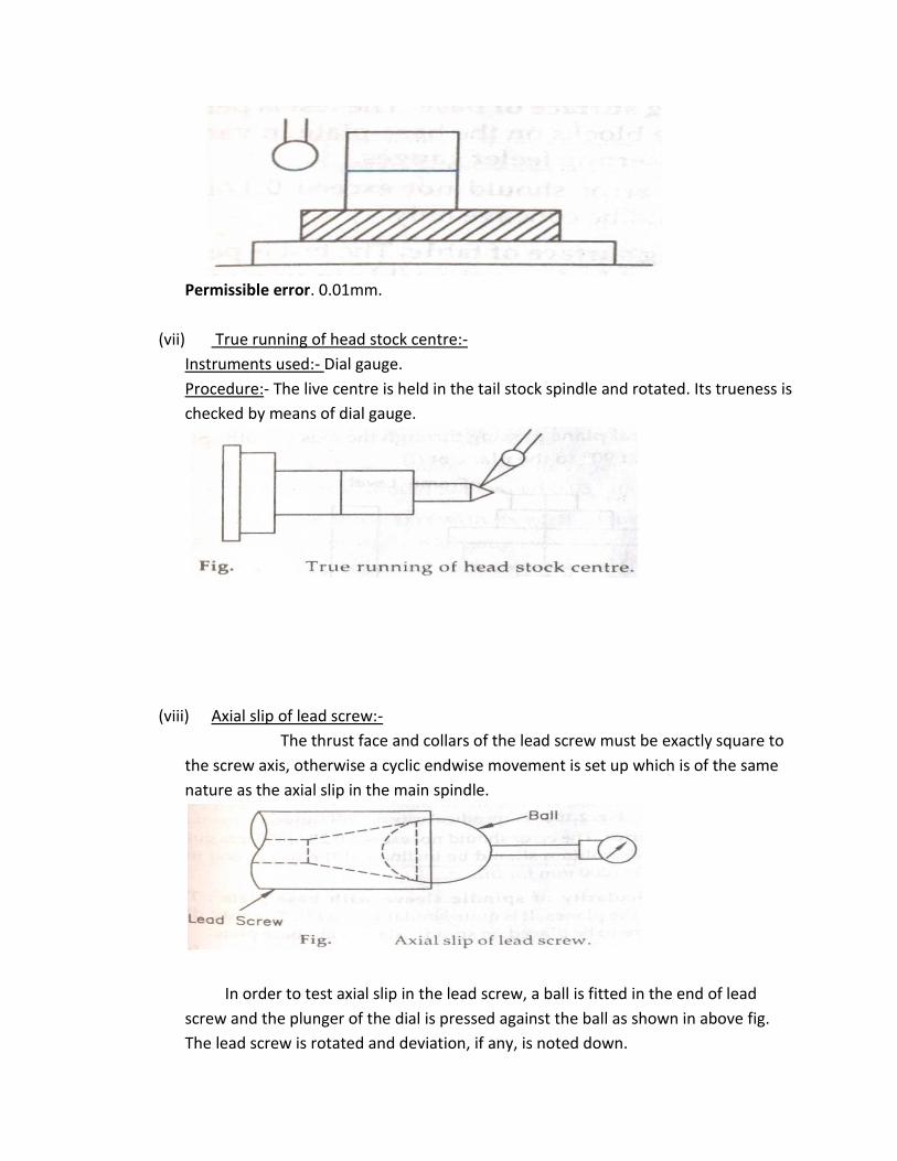
(vii) True running of head stock centre:-
Instruments used:- Dial gauge.
Procedure:- The live centre is held in the tail stock spindle and rotated. Its trueness is
checked by means of dial gauge.
(viii) Axial slip of lead screw:-
The thrust face and collars of the lead screw must be exactly square to
the screw axis, otherwise a cyclic endwise movement is set up which is of the same
nature as the axial slip in the main spindle.
In order to test axial slip in the lead screw, a ball is fitted in the end of lead
screw and the plunger of the dial is pressed against the ball as shown in above fig.
The lead screw is rotated and deviation, if any, is noted down.

ALIGNMENT TEST ON DRILLING MACHINES:-
There are two types of drilling machines:-
i. Alignment test on pillar type drilling m/c.
ii. Alignment test on radial drilling m/c.
(i) Alignment test on pillar type drilling m/c:-
(1) Flatness of clamping surface or base:-
The test is performed by placing a straight edge on two gauge
blocks on the base plate in various positions and the error is noted down by
inserting feeler gauges.
Permissible error:- The error should not exceed 0.1/1000 mm clamping surface
and the surface should be concave only.
(2) Flatness of clamping surface of table:-
The test is performed by placing a straight edge on two gauge
blocks on the table in various positions and the error is noted down by inserting
feeler gauges. In this permissible error is same as in flatness of clamping surface
of base (i.e., 0.1/1000 mm).
(3) Perpendicularity of drill guide to the table base plate:-
Instrument used:- Frame level.
Procedure:- The squareness of the drill head guide to the table is tested. The
test is performed by placing the frame level on guide column and table and the
error is noted by noting the difference between the readings of two level. The
level is measured in two conditions.
(i) In a vertical plane passing through the axis of both spindle and column.
(ii) In plane at 90˚ to the plane at (i)

Permissible error:- The error should not exceed 0.25/1000 mm guide column
for (i) and the guide column should be inclined at the upper end towards the
front only and 0.15/1000 mm for (ii).
(4) Perpendicularity of spindle sleeve with base plate:-
This test is performed in both the planes. It is quite similar to test (3). The
only difference is that frame levels are to be placed on the spindle sleeve and
base plate.
Permissible error:- The error should not exceed 0.25/1000 mm for plane (i) and
the sleeve should be inclined towards column only, and 0.15/1000 mm for
plane(ii).
(5) True running of spindle taper:-
Instrument used:- Test mandrel, dial gauge.
Procedure:- the test mandrel is placed in the tapered hole of spindle and a dial
indicator is fixed on the table and its feeler made to scan the mandrel. The
spindle is rotated slowly and readings of indicator noted down.
Permissible error:- the error should not exceed 0.03/100mm for machines.
(6) Parallelism of the spindle axis with its vertical movements:-
Instruments used:- Test mandrels, dial gauges
Procedure:- this test is performed into two planes(A) and(B) at right angles to
each other. The test mandrel is fitted into the taper hole of the spindle and the
dial gauge is fixed on the table with feeler touching the mandrel.
The spindle is adjusted in the middle position of its travel. The spindle
is moved in upper and lower directions of the middle position with slow vertical
feed mechanism and the readings of the dial gauge are noted down.

Permissible error:- 0.03/100mm for plane (A). 0.05/300mm for plane(B).
(7) Squareness of clamping surface of the table to its axis:-
Instruments used:- Dial gauge.
Procedure:- The dial indicator is mounted in the tapered hole of the spindle and
its feeler is made to touch the surface of the table. The table is then moved
slowly and the readings of the dial gauge noted down.
Permissible error:- It should be not exceed 0.05/300mm diameter.
(8) Squareness of the spindle axis with table:-
Instruments used:- Straight edge, dial gauge.
Procedure:- This test is performed by placing the straight edge in positions AA’
and BB’.
The work table is arranged in the middle of its vertical travel.

The dial gauge is mounted in the tapered hole of the spindle and its feeler is
made to touch the straight edge first at A and readings are taken. Then the
spindle is rotated by 180˚ so that the feeler touches at point A’ and again the
reading is taken. The difference of these two readings is the error in squareness
of spindle axis with table. Similar readings are taken by placing the straight edge
in position BB’.
Permissible error:- The permissible errors are 0.08/300mm with lower end of
spindle inclined towards column only for set up AA’ and 0.05/300mm for set up
BB’.
(ii) Alignment test on radial drilling m/c:-
(1) Saddle movement parallel to the base plate:-
Instrument used:- Dial gauge
Procedure:- A dial gauge is fixed to the spindle, with its plunger bearing on the
surface of the base plate, the saddle is then moved along the arm and the
readings are taken.
Permissible error:- Any deviation from parallelism with the base plate should be
on inclination upward towards the column, not exceeding 0.16mm per meter.
(2) To check the parallelism of arm itself as it rotates:-
A dial gauge is fixed in the spindle, with its plunger bearing on the surface of the
base plate. The arm is then rotated slowly on the column and the readings are
taken near the edge of the base plate, with its saddle in three different positions
as shown in fig.

Permissible error:- 0.16mm per meter.
(3) Spindle and feed movement square with base plate:-
Instrument used:- Dial gauge with suitable attachment for fixing horizontal rod
to the spindle.
Procedure:- To check the squareness of the spindle, a horizontal rod is fixed to
the spindle, with a dial gauge, attached at a radius of about 300mm, as shown in
fig. The plunger of the dial gauge is arranged to bear on the base plate and is
brought into the two positions shown in the figure by rotation of the spindle.
Readings should be taken with the spindle in four different positions, namely
near to and remote from the column with the arm first low and then high up on
the column.
Permissible error:- in any position, the departure from squareness should not
exceed 0.16mm per meter.
(4) Squareness of the feed motion:-
Instruments used:- Dial gauge, true square.
Procedure:- the dial gauge is held in the spindle with its plunger horizontal and
rearing on the dial gauge readings, as the spindle is moved up and down,
measure the error. The test should be performed with the spindle near to the
column and also at the end of the arm.

ALIGNMENT TEST ON MILLING MACHINE:-
(1) Flatness of work table:-
(a) In longitudinal direction
(b) In transverse direction
Measuring instrument:- Spirit level
Procedure:- A sprit level is placed directly on the table at points about 25 to 30
apart at A, B, C for longitudinal tests and D, E and F for the transverse test. After
that the readings are noted.
Permissible error:- Direction A-B-C, 0.04mm
Direction D-E-F, 0.04mm
(2) Parallelism of the work table surface to the main spindle:-
Instrument used:- Dial indicator, test mandrel 300mm long, sprit level.
Procedure:- The table is adjusted in the horizontal plane by a sprit level and is
then set in its mean position longitudinally. The mandrel is fixed in the spindle
taper. A dial gauge is set on the machine table, and the feeler adjusted to touch
the lower surface of the mandrel.

Permissible error:- 0.02/300mm
(3) Parallelism of the clamping surface of the work table in its longitudinal motion:-
Instruments used:- Dial gauge , straight edge
Procedure:- A dial gauge is fixed to the spindle. It is adjusted to touch the table
surface. The table is then moved in longitudinal direction and readings are
noted. If the table surface is uneven, it is necessary to place a straight edge on its
surface and the dial gauge feeler is made to rest on the top surface of the
straight edge.
Permissible error:- 0.02 up to 500mm length, 0.03 up to 1000mm and 0.04
above 1000mm length.
(4) Parallelism of the cross movement of the work table to the main spindle:-
(a) In a vertical plane
(b) In horizontal plane
Instrument used:- Dial gauge, test mandrel with taper shank.

Procedure:- The work table is set in its mean position. The mandrel is held in the
spindle. A dial gauge fixed to the table is adjusted so that its spindle touches the
surface of the mandrel. The table is moved cross-wise and the error is measured
in the vertical plane.
(Parallelism of the cross movement of the work table)
Permissible error:- 0.02 for the overall transverse movement of the work table.
(5) True running of internal taper of the main spindle:-
Instruments used:- 300mm long test mandrel, dial gauge
Procedure:- The test mandrel with its taper shank is held in the main spindle.
Dial gauge is kept scanning the periphery of the mandrel. Spindle is rotated and
dial gauge readings are noted at different points.
(True running of Internal taper of the main spindle.)
Permissible error:- 0.01 to 0.02mm .
(6) Squareness of the centre T- slot of work table with main spindle:-

Instruments used:- Dial gauge, special bracket.
Procedure:- To check the perpendicularity of the locating slot and the axis of the
main spindle. The table should be arranged in the middle position of its
longitudinal movement and a bracket in the locating slot. A dial gauge should be
fixed in the spindle taper. Observe the readings from the dial gauge.
Permissible error:- 0.025mm to 300mm.
(7) Parallelism between the main spindle and guiding surface of the overhanging
arm:-
Instruments used:- Dial gauge, mandrel
Procedure:- The over-hanging arm is clamped in its extreme extended position.
The dial gauge is fixed to the arbour support.
The feeler of the dial gauge is adjusted to touch the top or ride of the test
mandrel. The arbour support can then be moved along the over-hanging arm
and the deviation from parallelism observed on the dial gauge.

CHAPTER-4 SPECIAL CASTING AND POWER METALLURGY
CASTING – The process of pouring molten metal into the mould and allowing it to solidify is
known as casting.
Special Castings:-
(1) Die casting
(2) Investment casting
(3) Centrifugal casting
(1) Die Casting :-
- The process of forcing the molten metal into the metallic mould (die) cavity under
pressure and allowing it to solidify.
- Pressure is generally obtained by hydraulically or Pneumatically.
- The range of the pressure is (70 -5000) Kg/cm2
- The range of the pressure will be maintained during the solidification of casting.
- In this type of casting the liquid metal will be injected into the die.
- A die casting machine performs the following functions:
Holding two die halves firmly together.
Closing the die
Injecting the molten metal into die.
Opening the die
Ejecting the casting out of the die.
Die casting is of two types.
Hot chamber method
Cold chamber method

Hot Chamber Method of die casting:-
- In hot chamber machine the melting unit constitutes an integral part of the process.
The injection chamber is immersed in the molten metal at all times. At first the metal
is melted in melting pot. After the metal reaches the molten state, the injection
chamber is operated by air pressure which forces the metal into the die to complete
the casting. The air pressure is maintained till the solidification of casting. When the
solidification of the casting is completed the movable die will be opened. The die is
having two halves. One half is stationary die and another half is movable die.
Stationary is fixed one and movable die can be opened and closed. After opening of
the movable the casting is removed by the help of ejector pins.
Advantages –
- Simple in constriction
- Operation is simple.
- It requires less space.

Disadvantages–
(1) Production rate is lower.
(2) Compressed air does not produce pressure on molten metal.
(3) Life and efficiencies are less.
Applications – Hot chamber method of die casting can produce the casting of low melting point
metals such as zinc, tin and lead.
COLD CHAMBER METHOD OF DIE CASTING –
The molten metal is poured into the cold chamber and this molten metal is forced
hydraulically into the die is known as cold chamber method of die casting.
Process:- The metal is melted in a melting pot. In this method the melting pot is separated from
cold chamber machine. After the metal reaches into molten state, the molten metal is poured
into ladle. From the ladle the molten metal is poured into the cold chamber after the die is
closed and all cores are locked in position. The molten metal is entered into the die by the help
of hydraulic ram. The pressure required to force the metal into the die is of the order of (200-
2000) kg/cm2 and hence high squeezing action is exerted on the metal while it solidifies. Once
the casting has solidified, the movable half of the die opens. Cores are withdrawn, ram moves
to the backward and the ejector is advanced to force the casting out of the die half.
Advantages-

- Lower temperature of molten metal with higher injection pressure will produce
castings of dense structure.
- Sustained dimensional accuracy and free from blow holes.
- Increases its life and efficiency due to separation of melting pot and injection unit.
Disadvantages-
- It requires more area.
- Working parts are costly.
Applications-
- Aluminium, magnesium, brass and low melting points material can be cast.
(2) Investment Casting:-
It is a lost wax method of casting.
Process –
- The liquid wax is injected (150 – 170)0F into the metallic die at pressure (7 – 70)
kg/cm2. After cooling the wax mould is removed out of the metallic die. The silicate
slurry is prepared in a pot.
- The constituents of silicate slurry are 91.2% sand, 33.8% water, 6.5% calcium
phosphate 2.3% magnesium oxide and meshed silica. After the preparation of silicate
slurry is over then the wax mould is dipped in the solution of silicate slurry. The wax
mould can be dipped for 6 to7 time. Now the wax mould is coated with silicate slurry.
- The silicate moulds are allowed to cool in air. Then the moulds are taken into auto
clave machine. In auto clave machine the wax is removed out of the mould by the
application of steam. The wax from the silicate mould is collected in wax collector.

- The silicate mould is taken into pre-heater for pre-heating. Before pouring the molten
metal into the mould the pre-heating is required. Pre-heating is to remove vapours
and any wax linings present on inside wall of the mould.
- The metal is melted in a melting pot. After the metal reaches into molten stage, the
molten metal is poured into the ladle. From the ladle the molten metal is poured into
the silicate mould. Then the casting is allowed to cool and solidify in air.
Advantages:-
(1) Complex shapes which are difficult by any other methods are possible.
(2) Very close tolerance and excellence surface finish can be obtained.

(3) Little or no machining is required.
(4) Almost any metal can be cast.
(5) No flash on parting lines.
(6) Stronger components
(7) Strength is higher
(8) Light stressed wax impression dies have a very long life.
Disadvantages:-
(1) Expensive due to preparation of wax patterns and shell moulds.
(2) It is a time consuming process.
Applications:-
- Textile industries
- Automobile industries
- Food industries
- Oil gas industries
- Pump and valve industries.
(3) Centrifugal casting:-
The casting which utilizes the molten metal into the rotating mould.
The centrifugal casting is classified into three types
(1) True centrifugal costing
(2) Semi-centrifugal casting
(3) Centrifuging casting.
True centrifugal casting-

- In utilizes the forces generated by the centrifugal action to distribute the molten
metal in the rotating mould.
- Centrifugal force play a major role in shaping and feeding of the casting.
- Mould is rotated about its own axis at a predetermined speed.
- Moulds may be rotated about its horizontal axis or vertical axis.
- Moulds for longer parts may be rotated about its horizontal axis.
- Moulds for smaller parts may be rotated about its vertical axis.
- The molten metal for the cast part is introduced to the mould from an external source
by the help of a pouring spout. The liquid metal flows down into the rotating mould.
- The metal casting will harden as the mould continuous to rotate.
- By the help of the pipe puller the casting can be extracted from the mould.
- The forces play a major role for the solidification of casting.
- Due to the greater force in outer region of the rim that portion will be denser.

- All the impurities will remain in less denser region of metal casting, closer to the
centre of the axis of rotation.
- Impurities are solid inclusions and trapped air.
- The impurities will be removed by the machining process.
Advantages:-
- No use of sprues, risers or other gating systems.
- Good surface finish
- Quality castings with good dimensional accuracy can be produced.
- Material of high density and with few impurities is produced in the outer regions of
cylindrical parts.
- Large metal casting 10ft in diameter, and 50ft long can be produced.
- High melting point materials iron, steel can be cast.
- Core is not required.
Disadvantages:-
- All alloys cannot be cast.
- Small items cannot be cast by this process.
Applications:-

- Manufacturing of various tubes and pipes such as sewage pipes, gas pipes, water
supply lines, rings, bushing, the liner for engine cylinder, brake drums, street lamp
posts.
Semi centrifugal Casting:-
- The molten material for the metal casting is poured into a pouring basin and is
distributed through a central sprue to the areas of the mould. The forces generated by
the rotation of the mould ensure the distribution of molten material to all regions of
the casting.
- As the metal casting solidifies in a rotating mould the forces constantly push the
material out from the central sprue.
Centrifuging casting:-
- Centrifuging casting is the third main branch of centrifugal casting process used for
industrial manufacture of cast parts.

- In centrifuging casting moulds are arranged around the central sprue.
- These moulds contain all the necessary geometry for the cast part. Runners travel
from the central sprue to the mould entrances.
- The molten material is introduced into the central sprue. The entire system is rotated
about its axis with the central sprue at the centre of rotation. When an object is
rotated, forces are produced that act directly away from the centre of the axis of
rotation.
- The molten material moves into the moulds from the centre through the runners.
When the correct amount of molten metal to manufacture the casting is poured and
distributed completely into the moulds, the apparatus will continue to rotate as
solidification is occurring.
- During the solidification of the casting the moulds will be rotated. The forces acting on
the material farther from the centre are greater than the forces, those are acting on
the material closer to the centre.
- The material is dense at the outer region and the material is less denser at the area
closer of the centre of rotation.
- The impurities such as inclusions and trapped air will be deposited at the less denser
region.
- The impurities can be removed by the help of machining process.

Advantages:-
- Cast parts with thin walled sections can be manufactured.
- High density, high mechanical strength and fine grained structure can be produced.
- Desired shape can be manufactured.
- Great surface finish can be achieved.
Disadvantages:-
- All alloys cannot be cast.
- Small items can be produced.
Powder Metallurgy
Definition- It is a process of forming metal parts by heating compacted metal powders to
just below their melting points.
Flow chart of powder metallurgy:-

1. Metal powder is prepared from the metals.
2. The metal powders are mixed with additives (binders of Lubricants)
3. Forming of the mixed powder into compact form.
4. The compact powders are introduced into the die.
5. Then sintering will be started. Sintering of the compact to enhance integrity and
strength.
6. Sintering is the process of heating the powder at a temperature below the melting point
of the major constituents.
7. Sintering - (a) Solid phase sintering
(b) Liquid phase sintering
(a) Solid Phase sintering – In this the minor constituents will not turn into liquid stage.
(b) Liquid Phase Sintering – In this case the minor constituents will turn into liquid stage.
8. Secondary Operations:-
These are the finishing processers to the sintered part. Finishing processes are
annealing, polishing, machining if required, surface treatment to avoid corrosion.
Applications:-
- Manufacturing of brake linings, clutch plate, connecting rod crank shaft, cam shaft
and piston rings.
- Porous material such as bearing & filters can be manufactured.
- Tungsten filaments of electric bulb, radio valves, x-ray tube, oscillator valve.
- Military defence application.
- Atomic energy application.
- Manufacturing of grinding wheels.
- Clocks & timing devices, type writers, calculators, and permanent magnet can be
manufactured.
- Manufacturing of toothed components like gear.
- Material which are very difficult for machining- wire drawing dies, press tools, stone
hammers & rock drilling bits can be manufactured.

- Manufacturing of nozzles for rocket & missiles.
- Jet engine parts.
Advantages:-
- Accuracy is better
- Surface is good.
- Machining Processes are eliminated.
- Longer life of the product.
- Uniformity of structure.
- Void, blow holes are absent
- No material is wasted as scrap.
- Highly gratified labour is not required.
- Porous parts can be manufactured.
- Mixed powders of copper & lead can be successfully shaped by powder metallurgy.
- Product cost is cheaper.
- Hard tool bits can be formed.
Disadvantages:-
- Complicated shapes cannot be achieved.
- Don’t have good physical properties.

CHAPTER-5 NON CONVENTIONAL MACHINING PROCESS
Non conventional machining methods:
1. Electro discharge machining(EDM)
2. Electro chemical machining(ECM)
3. Abrasive jet machining(AJM)
4. Ultrasonic machining(USM)
5. Plasma arc machining(PAM)
6. Electron beam machining(EBM)
7. Laser beam machining(LBM)
1. Electro discharge machining:
- It has been recognized that a powerful spark, such as at the terminals of an
automobile battery will cause pitting of the metal at both the anode and the
cathode.
- Power is supplied from an AC service to a rectifier for generating the spark.
- DC output is then feed to the spark generation circuit.
- Tool, work and servomechanism are connected to the circuit.
- The function of the servomechanism is to maintain a very small gap between the
tool and work. The gap maintained is (0.025 to 0.75) mm.

- The tool and the work are submerged in dielectric fluid having poor electrical
conductivity.
- The spark is the transient electric discharge between the work and tool.
- When the potential difference (voltage) is sufficiently large across the gap the
dielectric fluid becomes ionized and breaks down to form the spark.
- The condenser discharges the current in the form of a spark.
- The time interval of spark is (10 to 30) microseconds.
- The current density is (5 to 500) A/mm2.
- The thousands of spark discharge occur/second across the gap between tool and
work which results a temperature 12000° C.
- At each discharge heat transfers from high temperature spark to both tool and work.
- It melts the metal in a thin surface layer.
- Work – anode
Tool – cathode
Dielectric fluids are based such as white spirit, paraffin, petroleum base hydrocarbon
fluids, transformer oil, kerosene and mineral oil.
Dielectric fluid cools the cutting zone.
Tool materials are based such as copper, brass, alloys of zinc and tin, hardened plain
carbon steel, tungsten carbide, graphite etc.
Advantages of EDM
- Complex shapes can be produced which are difficult to produce in conventional
methods.
- Extremely hard materials with very close tolerance can be achieved.
- There is no direct contact between work and tool. So delicate sections and weak
materials can be machined without any distortion.
- A good surface finish can be obtained.
- Very fine holes can be drilled.
- The chips, burrs can be easily cleaned from the surface due to the presence of
dielectric fluid.
- Cutting forces are zero.
Disadvantages of EDM
- Only electrically conducting materials can be machined by EDM.
- The low rate of material removal.
- Power consumption is very high.

- Excessive tool wear occurs during machining.
- Fire hazard associated with use of combustible oil based dielectrics.
- Cost is more.
- Time consuming process.
- Reproducing sharp corners on the work piece is difficult.
Application of EDM
- Manufacturing of the dies, press tools for the press machines.
- Manufacturing of moulds for the foundry shop.
- Manufacturing of the dies for the forging shop.
- Dies for the injection moulding machines.
- This process is useful for machining of small holes, orifices or slots in diesel fuel
injection nozzles, in air craft engines, air brake, valve etc.
- This process is suitable for machining burr free intricate shapes, narrow slots and
blind cavities etc.
2. Electro chemical machining (ECM):
- In ECM the principle of electrolysis is based for the removal of material from the
metal surface. The principle of electrolysis is based on Faraday’s laws of electrolysis.
- Work piece – anode , tool – cathode
- The tool is hollow tubular type to provide passage for circulation electrolyte
between the tool face and the work.
- As the power supply is switched on and the current starts flowing through the
circuit.
- Electrons are removed from the surface of the atoms of the work piece.

- The cat-ions tend to migrate to the hollow cutting tool.
- Before these ions can get deposited on the cutting tool face, these are swept away
by rapidly flowing electrolyte.
- The anions which move towards DC supply for the neutralization.
- The tool is fed towards the work piece automatically at constant velocity to control
the gap between the work and the tool.
- The sides of the tool are insulated to concentrate the metal removal action at the
bottom face of the tool.
- The electrolyte with burs form the tank is lifted by the help of pump and reused
again.
- The filter is provided for the filtration of burrs and dirt particles after the pump.
- The electrolyte is used 20% common salt (NaCl) solution. It acts as coolant during
metal removal.
Advantage of ECM:
- Tool does not contact the work piece. So less tool, wear, less heat and less stress are
produced.
- Tool can be repeatedly used.
- It is simple and versatile method.
- Surface finish can be extremely good.
- The process character does not depend upon the physical properties of the metal.
Disadvantages of ECM:

- High tool cost.
- 40000 Amps of current must be supplied. Power consumption is higher.
- The saline (acidic) electrolyte posses the risk of corrosion to tool, work piece and
equipment.
Applications of ECM:
- Die sinking operation
- Drilling jet engine turbine blades.
- Multiple holes drilling.
- Machining steam turbine blades within closed limits.
3. Ultrasonic machining (USM):
- Ultrasonic machining is a kind of grinding method.
- Abrasive slurry is pumped between tool and work.
- The equipment consists of a transducer, a tool holder and a tool.
- The linear oscillatory motion of the tool is obtained by transducer which converts
electric energy into mechanical energy.
- The transducer consists of a stack of nickel laminations those are wound with a coil.
- When a high frequency of current is passed through the coil changes in the electro-
magnetic field produce longitudinal strains in the laminations.
- These longitudinal strains are transmitted to the tool through a tool holder.

- The tool oscillates linearly with amplitude of about 0.05 mm.
- By the help of oscillation of the tool and abrasive slurry the material is removed
from the work piece.
- The tool is brazed, soldered or fastened mechanically to the transducer through a
too holder.
- The abrasive used in this process is aluminium oxide, boron carbide and silicon
carbide grains.
- The abrasive slurry can be prepared by taking the mixture of boron carbide and
silicon carbide and paraffin and aluminium oxide and paraffin.
- Water and paraffin acts as coolant.
- The tool used is may be copper, brass etc.
Advantages of USM:
- Good surface finish.
- Higher structure integrity.
- Any material can be machined.
- It can be machined hard, brittle, fragile and non conducting materials.
- No heat is generated in work, no change of physical structure of material.
- Non-metal can be machined.
- It is burr less and distortion less process.

Disadvantages of USM:
- Low metal removal rate.
- Tool wear rate is higher due to abrasive particles.
- Ultrasonic machining is used only when the hardness of work is greater than 45 HRC.
Applications of USM:
- Machining of hard, brittle and non-conductive materials.
- It is used chiefly for drilling holes, engraving.
- It is used for broaching and slicing etc.
4. Plasma arc machining (PAM):
- All the gases burning at high temperatures are ionized gases.
- In plasma arc machining, the gases are ionized by placing an arc across the path of
gas flow.
- The gas molecules get dissociated, causing large amounts of thermal energy to be
liberated. This generates high temperature which removes the metal by melting and
vaporization.
Process:
- An arc is struck between tungsten cathode and the water cooled copper anode.

- An inert gas such as argon is passed through a small chamber in which the arc is
maintained.
- As the gas flows out of the nozzle, it is heated and gets ionized the arc and forms the
coving plasma flame.
- The temperature of the plasma flame is (11000 to 28000)° C.
- The temperature melts the work piece surface and cuts.
- The cathode is eroded by the high spark temperature and must be adjustable.
Advantages of PAM:
- Easy to operate.
- A semiskilled operator can used this machine.
- It can cut both ferrous and non-ferrous materials.
- The plasma torch is easy to operate.
Disadvantages of PAM:
- Cutter’s electrode, nozzle sometimes requires frequent replacement which adds the
cost of operation.
- Non-conductive materials cannot be cut such as wood and plastic.
- Plasma arc leaves (4-6)° bevel on the cutting edge. This angle is visible in thicker
pieces.
Applications of PAM:
- Stainless steel and aluminium alloys cannot cut.

- Compared to ordinary flame plasma flame cuts the plain carbon steel four times
faster.
5. Abrasive jet machining (AJM):
- In this method the material is removed from the surface of the work piece by
colliding a focused jet of fine abrasive particles carried by compressed gas.
- The abrasive jet with compressed gas leaves through a nozzle at a velocity of the
order 300 m/sec and strikes the surface of the work piece producing impact loading
on it.
- Due to impact loading the micro-cracks occur and small chips of material get
loosened.
- The fresh surface is achieved.
- The abrasive material is used are aluminum oxide, silicon carbide and glass beads
etc.
Advantages of AJM:
- Flexibility and low heat production.

- Very good surface finish.
- Hard materials can be machined.
- Complete profiles can be created.
- Easily transportable of gas and abrasive material tank so any surface of the work
piece can be machined.
Disadvantages of AJM:
- Very slow rate of operation.
- Abrasive cannot be re-used.
- Slow material removal rate.
- Process produces a taper cut.
- Sometimes frequent replacement of nozzle brings an extra cost.
Applications of AJM:
- Ideal for cutting intricate profile out of brittle, hard, heat sensitive and thin materials.
6. Electron beam machining (EBM):
- Electron-beam machining is a metal removal process by a high velocity focused stream of
electrons which heats, melts and vaporizes the work material at the point of bombardment.
The production of free electrons is obtained from thermo-electronic cathodes wherein
metal are heated to the temperature at which the electrons acquire sufficient speed for
escaping the space around the cathode. The acceleration of the electrons is carried by an
electric field while the focusing and concentration are done by controlled magnetic fields.

The kinetic energy of a beam of free electrons is transformed into heat energy as a result of
the interaction of the electrons with the workpiece material. EBM is therefore, a thermo-
electric process.
- The figure shows the principle of operation of Electron-beam machining. Abeam of electrons
is emitted from the electron gun which is basically a triode consisting of
* A cathode which is a hot tungsten filament (2500˚C) emitting high negative potential
electrons.
* A grid cup, negatively based with respect to the filament.
* An anode which is heats at ground potential, and through which the high velocity
electrons pass.
- The gun is supplied with electric current from a high voltage D.C source. The flow of
electrons is controlled by the negative bias applied to the grid cup.
- The electrons passing through the anode are accelerated to two-thirds of the velocity of
light by applying 50 to 150 kV at the anode, and this speed is maintained till they strike the
workpiece.
- Due to the pattern of the electrostatic field produced by the grid cup, the electrons are
focused and made to flow in the form of converging beam through a hole in the anode.
- A magnetic deflection coil is used to make the electron beam circular having a cross
sectional diameter of 0.01 to 0.02 mm and deflect it anywhere.
- A built in microscope with a magnification of 40 on the work piece enables the
operator to accurately locate the beam impact and observe the actual machining
operation.
- As the beam impacts on the work piece surface the kinetic energy of high velocity
electron is immediately converted into the thermal energy and it vaporized the
material at the spot of its impact.
- The power density being very high (about 1.5 billion W/cm3) it takes a few
microseconds to melt and vaporize the material at the spot of its impact.
- The process is carried out in repeated pulses of short duration.
- The pulse frequency may range from 1 to 16000 Hz and duration may range from 4
to 64,000 micro seconds.
- The application of the above principle is also found in electron beam drilling in which
an organic or synthetic backing material is sandwiched on the other side of the
component.
- The beam rapidly penetrates the work piece, vaporizing it and reaches the backing
material which in turn vaporizes rapidly with an explosive release of vapour at high
pressure.
- The high vapour pressure of the backing material expels the original metal vapour
generated at the initial stage, making a clean hole.
-

Accuracy:
- Typical tolerances are about 10 % of slot width or hole diameter.
- Taper of about 4° included angle is present in slots and holes and this limits the
depth-to-width ratio.
- The depth-to diameter ratio can reach 20:1 with multiple pulses.
- Heat affected zones of up to 0.03 mm deep have been observed.
- The stock removal rate is generally in the region of 1.5 mm3/s with a penetration
rate of about 0.25 mm/s faster.
Application of EBM:
- To drill fine gas orifices, less than 0.002 mm, in space nuclear reactors, turbine
blades for supersonic aero engines.
- To produce metering holes in injector nozzles in diesel engines, etc.
- To scribe thin films.
- To remove small broken taps from holes.
Advantages and limitations:
- EBM is an excellent method for micro finishing.
- It can drill holes of cut slots which otherwise cannot be made.
- It is possible to cut any known material, metal or non-metal that can exist in
vacuum.
- Besides, there is no cutting tool pressure or wear.
- As a result, distortion-free machining having precise dimensions can be achieved.
- The biggest disadvantage is the high equipment cost and employment of high skill
operator.
- Besides, only small cuts are possible.
- Further, requirement of vacuum restricts the size of specimens that can be
machined.
7. Laser beam machining (LBM):
- A laser is a device which produces a beam of light.
- The laser light is the powerful source of power.
- The laser is pumped by a flash of high intensity light from a flash lamp.
- The lamp is fired by discharging a large capacitor through electric power (250-1000)
watts.

- The intense radiation from the lamp excites fluorescent impurity atoms to a higher
energy level.
- When the atoms fall back to the original energy level through the series of energy
levels, an intense beam of visible light is emitted.
- When the light is reflected back from the coated rod ends, more atoms are excited
and stimulated to return to their ground level.
- When this light is focused with ordinary lenses at a spot on the work piece, high
energy density is obtained which will melt and vaporize the metal.
Advantages of LBM:
- Flexibility
- Fully automated
- No solvent chemical is used.
- Holding the work in right position is easier.
- Do not require a lot of time for cutting.
- Use less energy as compared to plasma arc machining.
- Rubber, ceramic, wood and plastic can be machined.
- Elimination the risk of material contamination.
- Laser cutting is done by computer programming saving manpower.
- The chance of accidents and injuries are less due to less human involvement.
- Efficiency of the machine is very high.

- Reduced the chance of warping the material.
Disadvantages of LBM:
- High power consumption.
- Cutting plastic with laser, plastic emits fumes which subjected to heat. The fumes
released can be toxic.
- Carelessness in adjusting the laser distance and temperature may lead to burning of
some materials.
Applications of LBM:
- It can be used for drilling, scribing, cutting and shaping.
- Drilling holes in rubber baby bottle nipples, holes in nylon buttons, holes in surgical
needles, flow holes in oil or gas orifices etc.
- To drill holes in diamond dies.
- Aerospace application
- For cutting of non-metals.