2016 technology recumbent recline in style! · pdf fileintroduction dear customer, thank you...
TRANSCRIPT

Operating manual and service instructions for HP Velotechnik tricycles
Sept. 2015
. . .recline in style!2016 recumbenttechnology
HPwww.hpvelotechnik.com
Velotechnik

The upper picture shows the Scorpion fs 26 S-Pedelec, the lower picture shows the Scorpion fs 26. Relevant component are alike on all tricycles depending on the model and individual configuration.
Parts marked with "*" are options or required for S-Pedelec when using on public roads in the scope of German StVZO (German traffic regulations) Parts marked with " **" belong to the optional electric assist system.

Introduction
Dear customer,
thank you for buying a recumbent tricycle designed by HP VELOTECHNIK and congratulations on the purchase of your new recumbent tricycle! With this high-quality touring tricycle, you will enjoy many years of ex-hilarating riding pleasure.
Your safety and your satisfaction are our main concern. On the follow-ing pages, this manual will inform you about important safety issues as well as maintenance and care instructions.
Even if you have many years of experience with bicycles please do take your time to read this manual carefully before the first ride. Your re-cumbent tricycle is designed with the latest recumbent technology by HP VELOTECHNIK that partly needs special treatment and care.
In this manual you will find detailed instructions on how to optimize your tricycle to meet your demands and riding style as well as your size and weight. In addition to this, we have put together a collection of in-formation on care and maintenance as well as special technical advice from our engineers. Important: Please send us the attached warranty registration form for your extended warranty (see page 88.)
This guide helps you to keep your tricycle in perfect condition so you will always experience maximum fun, comfort and safety.
Enjoy yourselves and have a great ride!
Paul J.W. Hollants, Dipl.-Ing. Daniel Pulvermüller
and the HP VELOTECHNIK team
Content
Safety instructions 2 General safety instructions 2 Intended use 5 Load capacity 5 Final assembly 6 Bolts and nuts 7 Quick release levers 7 The first miles 8 Safety instructions (bicycle) 9 Legal requirements 9 No alteration of parts 9 Frame number and identification marks 9 Added parts and accessories 10 Fairings 11 Replacement of parts 11 Do not take kids with you 11 Pedelec system 11 Trailer on Scorpion fs 26 /Enduro, Scorpion plus 20 and Scorpion plus 26 11
Trailer on Scorpion, Scorpion fx, Scorpion fs 20, Scorpion plus 20 12
Trailer on Gekko fx 20 and Gekko fx 26 12 Safety instructions (S-Pedelec) 13 Legal requirements 13 Exchanging parts 13 Identification plate 14 Added parts and accessories 14 S-Pedelec system 15 No riding without accumulator 15 No alteration of parts 15 Do not take kids with you 15 Trailers 15 Riding a recumbent tricycle 16 Learning the new riding technique 16 Handling instructions 16 How to ride correctly and safely 17 Slowly increase the strain 18 Adjusting your new tricycle 19 Adjusting the seat position 19 The BodyLink-seat for Scorpion, Scorpion fx, Scorpion fs 20, Scorpion fs 26 /S-Pedelec /Enduro, Scorpion plus 20 /plus 26 19
The ErgoMesh-seat for Scorpion, Scorpion fx, Scorpion fs 20, Scorpion fs 26 /S-Pedelec /Enduro, Scorpion plus 20 /plus 26 22
The Gekko fx 20 mesh-seat 23 The head rest 24 Adjusting to your size 25 Adjusting the front boom 25 Adjusting the length with front boom quick adjust 28
Adjusting the handlebars 29 A good setting for the handlebars 29 Setting the width and angle on Scorpion, Scorpion fx, Scorpion fs 20, Scorpion fs 26 /S-Pedelec /Enduro, Scorpion plus 20 /plus 26 29
Setting the angle of the handlebar on Gekko fx 20 and Gekko fx 26 30
Adjusting the cable length 31 Handlebar grips 31 Folding 32 Taking off the seat 32 Folding of Scorpion, Scorpion fx, Scorpion fs 20 32
Folding the Scorpion fs 26 /Enduro /S-Pedelec, Scorpion plus 20 /plus 26 33
Folding the Gekko fx 20 and Gekko fx 26 36 Lighting system 41 Lighting systems for bicycles 41 Lighting system of Scorpion fs 26 S-Pedelec 43 Brakes 44 Handling of the brakes 44 Maintenance of the brakes 45 Cable operated (mechanical) brakes 46 Hydraulic brakes 46 Gear system and chain 48 Handling of the gear system 48 Adjusting the gear system 49 Chain 50 Chain tubes 51 Replacing the tubes 52 Chain roller 53 Wheels 55 Disassembling the wheels 55 Tyres 55

Content
Con
tent
Front wheels of all Scorpion and Gekko models 56
Rear wheel of Scorpion, Scorpion fx, Scorpion fs 20, Scorpion plus 20 and Gekko fx 20 56
Rear wheel of Scorpion fs 26, Scorpion plus 26 and Gekko fx 26 56
Wheels of Scorpion fs 26 S-Pedelec 56 Spokes 57 Headset 58 Adjusting the headset on Scorpion, Scorpion fx, Gekko fx 20 and Gekko fx 26 58
Wheel alignment 59 Measuring toe-setting on Scorpion, Scorpion fx, Gekko fx 20 and Gekko fx 26 59
Measuring toe setting on Scorpion fs 20, Scorpion fs 26 /Enduro /S-Pedelec, Scorpion plus 20 and Scorpion plus 26 59
Adjusting toe setting 59 Setting of camber angle on Scorpion fs 20, Scorpion fs 26 /Enduro /S-Pedelec, Scorpion plus 20 and Scorpion plus 26 (informations for bicycle mechanics) 62
Adjusting the suspension 64 Suspension and damping of Scorpion, Scorpion fx /fs 20 /fs 26 /Enduro /S-Pedelec, Scorpion plus 20 /plus 26 64
Rear suspension element 66 Adjusting the rear suspension element of all Scorpion models 66
Steel spring rear shock DV-22 66 Air shock ROCKSHOX Monarch 69 Front suspension elements 72 Adjusting and maintenance on the front suspension of Scorpion fs 20, Scorpion fs 26 /Enduro /S-Pedelec, Scorpion plus 20 and Scorpion plus 26 72
Swing arm pivot 79 Swing arm pivot on Scorpion models 79 Mudguards 80 Front mudguards 80 Mounting of front mudguard on Scorpion fs 20, Scorpion fs 26 /S-Peldelec, Scorpion plus 20 / plus 26 80
Mounting of front mudguards on Scorpion, Scorpion fx, Gekko fx 20 and Gekko fx 26 81
Water bottle cages 82 Water bottle cage 82 Water bottle cages for ErgoMesh- and Gekko-seats 82
Water bottle cages for BodyLink-Sitz 82 Maintenance and care 83 Maintenance routine 83 Wear and tear 83 Cleaning and conservation 83 Storing the bicycle 85 Transport in the car 85 Tightening torques 86 Table of tightening torques for all Scorpion models 86
Tightening torques for Gekko fx 20 and Gekko fx 26 87
Warranty 88 Warranty policy 88 Warranty pass 89 Service plan 97

2
General safety instructions The manuals of component manufacturers such as the brake manufacturer, the gear sys-tem manufacturer, and the pedal manufac-turer also belong to this manual. They give detailed information on operating and main-taining these specific parts. Please read the manuals of the part manufacturers as carefully as this manual. Please provide this manual to any other user of your recumbent before us-ing it.
The maintenance and adjustment of this re-cumbent partly requires special tools and skills. Do only works within your limits and, for the purpose of your own safety, do not go beyond.
Should you be uncertain at any point, get in contact with your local dealer. The instruc-tions in this manual apply only to a completely assembled HP VELOTECHNIK tricycle with stan-dard parts from the series production of HP VELOTECHNIK. On special demand HP VELOTECHNIK delivers frame kits to put a specialist dealer in a position to assemble a tricycle individually. In this case the manuals on the operation and maintenance of the parts only represent a guideline, please read every manual of every part manufacturer separately.
The specialist dealer is responsible for the ex-pert assembly, please contact him for detailed information! A tricycle that has been assem-bled from a frame kit must always be tested and approved by a qualified bicycle mechanic before your first ride.
The texts in the grey boxes are particularly important for your safety. Please read them carefully. The signs explained below will be used in this document without bee-ing explained again!
Danger! Texts that begin with "Danger!" mark an immediate danger for your life and your health. Please read them carefully.
Attention! Hints with the text "Attention" are important for your safety1
Safety instructions

General safety instructions
3
Safe
ty in
stru
ctio
ns Gekko fx 20
Gekko fx 26
Scorpion
Scorpion fx
Scorpion fs 20

General safety instructions
4
Scorpion fs 26
Scorpion fs 26 Enduro
Scorpion fs 26 S-Pedelec
Scorpion plus 20
Scorpion plus 26

General safety instructions
5
Safe
ty in
stru
ctio
ns Intended use
Your HP VELOTECHNIK tricycle is a bike for the use on streets and paved roads.
This tricycle is not designed for the use in rac-ing and off-road riding, for jumping or acro-batics, and you must not ride across curbs, stairs, etc.
The Scorpion fs 26 Enduro is a bicycle that can additionally be used on unpaved roads.
The Scorpion fs 26 S-Pedelec belongs to the EU-vehicle classification category L2e (three-wheel moped) with speeds of up to 45 km/h (28 mph).
Using your bike on public roads is only al-lowed if it has been equipped with the acces-sories that are required by the applicable traffic regulations of the country in which you are using it.
Never drive without holding on! Before your first ride, read the chapter “Riding a recum-bent tricycle” on page 17 and get carefully used to the different vehicle performance.
Damage through inappropriate use, assembly errors, accidents or similar activities and wilful damage results in the loss of any warranty.
The intended use also includes the precise observation of the prescribed usage and main-tenance regulations and instructions.
Load capacity
It is important to adjust the spring stiffness of the suspension according to the load, see the chapter about adjusting the suspension in this manual, page 65.
Scorpion fx, Scorpion fs 26 /Enduro /S-Pedelec
The maximum load (rider + luggage) is 140 kg (308 lbs). The maximum total weight (bicycle + rider + luggage) is 160 kg (352 lbs). The lo-wer limit is valid. With a coupled trailer, the maximum total weight must not exceed 160 kg (352 lbs). When riding the Scorpion fs 26 Enduro on unpaved roads the maximum load is 110 kg (242 lbs), the maximum total weight is 130 kg (286 lbs).
The permitted axle load is 100 kg (220 lbs) on the front axle and 95 kg (209 lbs) on the rear axle.
Scorpion, Scorpion plus 20 /plus 26
The maximum load (rider + luggage) is 150 kg (330 lbs). The maximum total weight (bicycle + rider + luggage) is 170 kg (374 lbs). The lower limit is valid. With a coupled trailer, the maximum total weight must not exceed 170 kg (374 lbs).
Scorpion fs 20, Gekko fx 20 and Gekko fx 26
The maximum load (rider + luggage) is 130 kg (286 lbs). The maximum total weight (bicycle + rider + luggage) is 150 kg (330 lbs). The lower limit is valid. With a coupled trailer, the maximum total weight must not exceed 150 kg (330 lbs).

General safety instructions
6
Danger! Additional loading can influence the handling of your tricycle con-siderably. If you plan on riding with heavy luggage we advise you to make a test ride on a street with no traffic to get used to the new situation.
The load should be placed as close to the body of the rider as possible, since this results in better riding performance. You can also improve the handling of the tricycle by posi-tioning the centre of gravity of the luggage as low as possible, so pack heavy items in the bottom of your panniers.
Take care that your luggage is safely stored on the racks. Bags must be tightly fastened to the racks so they can not move. Make sure that loose parts like straps or belts can not touch the wheels, the derailleur, or the suspension.
The rear rack is designed for standard tricycle panniers. On Scorpion tricycles with 26 inch rear wheels, only side bags can be used.
Take care that your luggage does not cover the lighting system and the reflectors of your tricycle and that they stay fully functional.
Maximum load for carriers:
The maximum load on the rear rack is 25 kg (55 lbs).
The maximum load on the lowrider rack for Scorpion fx, Scorpion plus 20 and Scorpion plus 26 is 25 kg (55 lbs).
Carrier on Scorpion fs 20
Lowrider on Scorpion fx
Final assembly
Your tricycle has been delivered to your spe-cialist dealer only partly assembled.
Your dealer has to have carefully finished the assembly, perhaps altered the specification of your tricycle to meet your special require-ments and performed a test ride. Please make sure that this pre-delivery service is recorded in the Warranty Pass at the end of this man-ual.
All screws must be checked and tightened, especially on the handlebar, stem, knuckles, swing arm pivot and wheels. Please follow the tightening torque settings listed in the table on page 88.
Derailleurs and brakes must be checked and adjusted. Please follow the instructions in the manuals of the parts manufacturers that come with this manual.

General safety instructions
7
Safe
ty in
stru
ctio
ns Bolts and nuts
Screws gradually settle in and hence they can come loose. Therefore check the screws regularly if they are tightened appropriately with a torque wrench.
In the tables on page 88 and 89 you will find the prescribed tightening torques, they refer to greased screws!
Attention! Screws must be tightened with prescribed tightening torque. In this manual tightening torques are given in "Nm“ (Newton meter). Always use a torque wrench wherever a torque setting is given in this manual. Never rely on "feeling". Screws tightened too much or not enough can break, which can lead to dangerous accidents. In case you don't own a torque wrench have your bicycle me-chanic do the respective work. You will find tables with the prescribed torque set-tings on page 88 and 89 in this manual.
The grease also prevents your screws from seizing in their threads so that they won't un-screw anymore. In particular, screws made of stainless steel are susceptible to this and therefore have always to be put in with grease.
Do use high quality acid free grease, if possible a lubricant with added solid particles like Tef-lon or MoS2. Their ingredients still work properly after the thinner grease has been removed from the contact surfaces.
Alternatively you can use thread locker that you apply to the screw before you put it into the thread.
Always check the screws very diligently for signs of corrosion. Rust at the screw heads may also lead to the screw seizing in the
thread. When the metallic and shiny coating of galvanised screws comes off and discloses dull, gray-brown steel you have to exchange the screw.
When you exchange screws please only use screws of the same type. Screws come in dif-ferent strength classes. Please only use galva-nised screws of the same type and strength, corresponding to the German strength class 8.8 or stainless steel screws grade A2-70, when not given any other recommendation. If you are in doubt please ask your specialist dealer.
Quick release levers
Quick release levers hold wheels and seat in position.
A quick release lever consists of two basic parts: the lever on one side provides the clamping force. With the adjusting nut on the other side you adjust the clamping tension on the screw thread.
Danger! An incompletely or im-properly closed quick release can result in parts coming loose and hence in a crash, possibly resulting in serious injury.
To open the quick release, move the lever away from the frame. In doing so the inscrip-tion "open" should be visible on the lever.
To close the quick release, move the lever with power in the other direction so that the word "close" is visible on the outward side of the lever. At the start of the lever's motion, for, say, half of its movement, the lever should move very easily, without any clamping action.
In the second half of the lever's movement the force on the leer should increase considera-

General safety instructions
8
bly, corresponding in the end to 15-20 kg (46 lbs).
In its final position, the lever should come parallel with the tricycle and should not stick out to one side.
Check the security of the lever by attempting to twist the lever. If the lever can be made to pivot around in a circle the clamping is too loose. You must re-open the quick release, hold the lever and increase the clamping ten-sion. Do this by screwing the adjustment nut on the other side by half a turn. Close the lever and check the clamping anew.
Finally, check that the part being secured is firmly fixed: Lift each wheel several inches off the ground and give it a slap onto the tire from above. A properly fixed wheel will re-main secure in the frame's dropouts.
Parts that are fastened with a quick release open easily. Thus, they are more susceptible to theft. Therefore, always secure the wheels with a lock when you park your tricycle. It is also possible to exchange the quick releases with special security screws (e.g. from PITLOCK) that can only be opened with a spe-cial tool. For this please consult your local specialist dealer.
Danger! Check the proper set-ting of quick release levers always before riding, especially when the bicycle has been unattended.
The first miles
The first 300 km (186 miles) are an important for breaking in the tricycle. During the first use of a new tricycle the screws may settle and become loose. Cables and spokes may
stretch. Bearings may show play. Please be very attentive during that period.
After 300 km or after two months at the lat-est you will have to take your tricycle to a bi-cycle mechanic for the first service. Please record this first service and the works per-formed in the warranty pass on page 91. This first service is the prerequisite for further use of the tricycle and for your warranty claims.

9
Safe
ty in
stru
ctio
ns
Safety instructions (bicycle) Legal requirements
When you ride your tricycle on public roads it must comply with national legislation and guidelines. They will vary from country to country.
In general, there are minimum standards for brakes, reflectors and lighting systems, as well as usually a general duty to ensure that your vehicle is in roadworthy safe condition. There will also be a duty to ride in a safe and re-sponsible manner. If you ride your HP VELOTECHNIK tricycle in traffic you should be sure to observe all the applicable laws and regulations.
In most countries, including Germany and the UK, two independent braking systems are re-quired. Do not ride with only one brake working! Please contact your local dealer to find out about your legal obligations.
In the scope of German StVZO your equip-ment has to meet the following requirements:
• two functional, independent brakes • a dynamo or battery driven lighting system
with a white headlight aiming forward whose beam center touches the road 10 m ahead
• a red taillight and a red rear reflector which may be combined
• at least one white reflector aiming forward and a red large area reflector with “Z” label aiming to the back
• two yellow reflectors attached to the spokes in every wheel; may be substituted by tires or rims with white reflective ring
• yellow pedal reflectors on both sides for the pedals
• a bell
As an addition, we recommend to mount a flag on a pole for better visibility in traffic. You can find a bracket for the pole at the rear rack or the rear light mount.
The safety equipment on your tricycle must be checked before every ride and maintained in proper condition.
Traffic regulations may change. Please check currently valid regulations or ask your special-ist dealer.
No alteration of parts
Attention! You are not allowed to perform any work on the parts of the tricycle, especially frame, fork, handlebar and seat, which might endanger their solid-ity.
These works include drilling holes, welding, brazing, paint methods that add heat or any other chemical treatment. If any of these works is done improperly it may result in a loss of strength by direct damage or increased susceptibility to corrosion.
Frame number and identification marks
The frame number is placed on the postions described below. If needed, an additional iden-tification number can be engraved at the de-scribed places on the frame.
However, we recommend to use adhesive stickers for additional identification numbers.
Scorpion fs 26 /Enduro /S-Pedelec, Scor-pion plus 20, Scorpion plus 26
The frame number is placed on the inner side of the gusset plate at the main frame rear end.
For additional identification numbers on Scor-pion fs 26 and Scorpion plus models, use the area below the cable guidance on the upper side of the seat tube (facing to the main frame).

Safety instructions (bicycle)
10
Position for identification mark on the Scorpion fs 26 frames
Scorpion, Scorpion fs 20 and Scorpion fx
On Scorpion, Scorpion fs 20 and Scorpion fx use the lower stay on the right side of the gusset sheet for identification numbers, as like the position of the frame number on the other side.
Position of frame number on Scorpion fs 20 and Scor-pion fx
Gekko fx 20, Gekko fx 26
On Gekko fx 20 and Gekko fx 26 frames, the identification number can be engraved besides the frame number on the cross tubes gusset sheet. (Some older models have the frame number engraved on the rear end between the chain stays facing to the tire.)
Position of frame number on Gekko models
Added parts and accessories
Attention! Mounting additional parts or accessories is at your own risk. It is important that you carefully read the in-stallation guide of the manufacturer. Addi-tions to the handlebar like fairings, handlebar fittings, bottle holders, etc. may impair your safety due to additional loading or clips with sharp edges.
Additional accessories may impair the func-tion of your recumbent tricycle. We advise you to generally ask your dealer before you mount any special parts or accessories to your tricycle.
Take care that the handlebar and the suspen-sion always stay moveable. You must not add any parts to the handlebar or the seat that might endanger the rider through sharp edged or pointed shapes while steering, getting on and off the tricycle or bumping against some-thing.
Before you purchase a bell or a lighting sys-tem make sure that these accessories con-form to your national laws and regulations.
Additional accessories may invalidate the op-erating licence or impair the function of your S-Pedelec. This may also be valid for accesso-

Safety instructions (bicycle)
11
Safe
ty in
stru
ctio
ns ries and parts that are not in the category of
parts that can only be exchanged with parts identical in construction. Before mounting parts and accessories, it is recommended to contact your bicycle dealer or a vehicle ex-amination organisation (like TÜV, Dekra, GTÜ...).
Check the special safety instructions for the S-Pedelec on page 13.
Fairings
As a front fairing for recumbent tricycle, you may use the Streamer fairing offered by HP VELOTECHNIK. Please take care to assure a good vision over the fairing and sufficient freedom of movement below.
Please take into account that any fairing makes the tricycle more prone to crosswind influ-ences. In strong wind or gusts of wind unsafe situations may occur. Please remove the fair-ing before riding in such weather conditions.
Front fairing „Streamer“on the Scorpion tricycle
Replacement of parts
The replacement of parts relevant for safety (especially brakes, lighting system, stem, han-dlebar, knuckles, drive train, suspension ele-ments) should only be done with original parts by a bicycle mechanic, since it requires a certain degree of skill, suitable tools and me-chanical aptitude.
Any technical change you perform on your own is at your own risk!
Danger! If any part is deformed (e.g. due to an accident or overload), espe-cially frame, knuckles, handlebar, seat mountings, pedals, cranks and brakes, it is not allowed to use it any further or repair it. Do not try to straighten bent parts. You must replace them for your own safety. If you do not replace a damaged part it can result in a total failure of the part and you may be seriously injured!
Do not take kids with you
HP VELOTECHNIK tricycles are not designed for the transport of children. You are not al-lowed to mount a child's seat. It is only al-lowed to transport children in a trailer that has been specially designed for that purpose.
Pedelec system
Instructions for the use and safety of the op-tional pedelec systems are referred in the sys-tems manufacturer's manuals. Please read them carefully before use.
Trailer on Scorpion fs 26 /Enduro, Scorpion plus 20 and Scorpion plus 26
You are allowed to use trailers (double trail only) up to 40 kg (88 lbs).
We recommend using a trailer hitch mounted to the rear dropout. Please make sure the maximum allowed load on the trailer hitch is not exceeded.
Always check that the suspension and the trailer still work properly after you have mounted the trailer.
When using pedelec systems, you may need special accessories from HP VELOTECHNIK to mount the trailer coupling.

Safety instructions (bicycle)
12
Trailer on Scorpion, Scorpion fx, Scor-pion fs 20, Scorpion plus 20
You are allowed to use trailers (double trail only) up to 40 kg (88 lbs). When using a rear rack, you will need our special HP VELOTECHNIK / WEBER coupling.
Please make sure the maximum allowed load on the trailer hitch is not exceeded.
ZWEIPLUSZWEI offers a special, lowered cou-pling for Chariot trailers on 20 inch rear wheels.
Always check that the suspension and the trailer still work properly after you have mounted the trailer.
When using pedelec systems, you may need special accessories from HP VELOTECHNIK to mount the trailer coupling.
Trailer on Gekko fx 20 and Gekko fx 26
You are allowed to use trailers (double trail only) up to 40 kg (88 lbs). When using a rear rack, you will need our special HP VELOTECHNIK / WEBER coupling.
Please make sure the maximum allowed load on the trailer hitch is not exceeded.
ZWEIPLUSZWEI offers a special, lowered cou-pling for Chariot trailers on 20 inch rear wheels.

13
Safe
ty in
stru
ctio
ns
Safety instructions (S-Pedelec)
Attention! The situation de-scribed below is valid for Germany only. For legal requirements in your country, please contact the authorities.
Legal requirements
According to law, the Scorpion fs 26 S-Pedelec is not a bicycle but a motor vehicle class L2E (three-wheeled small motorcycles with a maximum design speed up to 45 km/h). The construction speed, that is the speed that the vehicle will reach without using muscle power, is 20 km/h. With additional power from the rider’s muscles, up to 45 km/h can be reached. At that speed, the motor assis-tance is switched of completely.
To be allowed to use the S-Pedelec on public roads, there must be an operating licence for it and it must be equipped with a insurance plate.
The operating licence is provided by HP VELOTECHNIK together with the vehicle and needs to be handed out to the customer by the dealer. The keeper of the Scorpion fs 26 S-Pedelec must contract a motor vehicle liability insurance and will receive an insurance plate in doing so.
The operating licence already assures that the S-Pedelec meets all legal requirements for tak-ing part in public traffic in Germany by the time it is being put into operation. The rider always has to carry the operating licence and the insurance card while riding.
By the time this manual was edited the follow-ing regulations apply in Germany:
The rider must wear a proper helmet while riding the S-Pedelec.
To ride the Scorpion fs 26 S-Pedelec a driving license class M or AM is required.
Please catch up on present regulations in your country regarding driving licences, the use of bicycle lanes, riding on paths away from the road, wearing helmets etc. frequently.
Exchanging parts
Exchanging parts may invalidate the operating licence of your S-Pedelec.
When issuing the operating licence some parts are defined that can only be exchanged by parts identical in construction. Such are:
• frame parts • chassis parts • wheels • propulsion unit: motor, accumulator, con-
sole • brakes • lighting system • handlebars, stem • console for insurance plate and rear light
and license plate illumination
The following parts are only allowed to be exchanged by parts including design approval: • tires (see p. 58) • rear mirror
The following parts may be exchanged by parts recommended by HP VELOTECHNIK:
• springs and dampers • brake pads • seat (BodyLink to ErgoMesh or ErgoMesh
XL and vice versa, not ErgoMesh HS or BodyLink with long seat connection sheets)
• fenders
Safety instructions (S-Pedelec)
14
Parts with no exchange restrictions are the following:
• gearing system, chain rings, sprockets • cranks • pedals (with reflectors incl. design approval) • grips • tubes
Danger! If any part is deformed (e.g. due to an accident or overload), espe-cially frame, knuckles, handlebar, seat mountings, pedals, cranks and brakes, it is not allowed to use it any further or repair it. Do not try to straighten bent parts. You must replace them for your own safety. If you do not replace a damaged part it can result in a total failure of the part and you may be seriously injured!
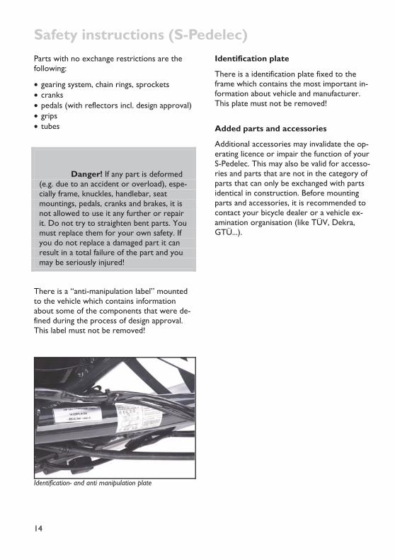
There is a “anti-manipulation label” mounted to the vehicle which contains information about some of the components that were de-fined during the process of design approval. This label must not be removed!
Identification- and anti manipulation plate
Identification plate
There is a identification plate fixed to the frame which contains the most important in-formation about vehicle and manufacturer. This plate must not be removed!
Added parts and accessories
Additional accessories may invalidate the op-erating licence or impair the function of your S-Pedelec. This may also be valid for accesso-ries and parts that are not in the category of parts that can only be exchanged with parts identical in construction. Before mounting parts and accessories, it is recommended to contact your bicycle dealer or a vehicle ex-amination organisation (like TÜV, Dekra, GTÜ...).

Safety instructions (S-Pedelec)
15
Safe
ty in
stru
ctio
ns Fairings
As a front fairing for Scorpion fs 26 S-Pedelec you may use the Streamer fairing offered by HP VELOTECHNIK. Please take care to assure a good vision over the fairing and sufficient freedom of movement below.
Please take into account that any fairing makes the tricycle more prone to crosswind influ-ences. In strong wind or gusts of wind unsafe situations may occur. Please remove the fair-ing before riding in such weather conditions.
The front fairing„Streamer“ on the S-Pedelec
S-Pedelec system
Instructions for the use and safety of the S-Pedelec systems are referred in the systems manufacturer's manuals. Please read them carefully before use.
No riding without accumulator
According to the regulations in your country, it might not be allowed to ride the Scor-pion fs 26 S-Pedelec without a properly charged accumulator installed. The accumula-tor provides electric energy for lighting sys-tem and brake light. Without accumulator, these features will not work.
No alteration of parts
Attention! You are not allowed to perform any work on the parts of the tricycle, especially frame, fork, handlebar and seat, which might endanger their solid-ity.
These works include drilling holes, welding, brazing, paint methods that add heat or any other chemical treatment. If any of these works is done improperly it may result in a loss of strength by direct damage or increased susceptibility to corrosion.
Do not take kids with you
The transport of children with the Scor-pion fs 26 S-Pedelec is not allowed. You are not allowed to mount a child's seat.
Trailers
Towing a child trailer is not allowed.
It is allowed to tow a trailer for goods (multi-track only). It must be type approved. Its weight must not exceed 40 kg.
We recommend using a trailer hitch mounted to the rear dropout. Please make sure the maximum allowed load on the trailer hitch is not exceeded. Always check that the suspen-sion and the trailer still work properly after you have mounted the trailer.
Because of the S-Pedelec system of Scorpion fs 26 S-Pedelec, you may need special acces-sories from HP VELOTECHNIK to mount the trailer coupling.

16
Riding a recumbent tricycle Learning the new riding technique
Your new tricycle has been assembled by your dealer and adjusted together with you as described on the pages 19 and following in the chapter "Adjusting your new tricycle". Before you sit down on your tricycle and enjoy your first ride please make yourself familiar with the instructions on riding technique and han-dling.
To ride this recumbent you will have to make yourself acquainted with the different riding position. Make sure that you and all other fu-ture users of this tricycle will have read this manual carefully prior to the first ride. If you are in doubt please consult your local dealer.
Before the first ride the users of this recum-bent have to practice and make themselves familiar with the different handling. We rec-ommend to practice on a quiet road away from traffic. Before you ride the tricycle in traffic you must master the handling com-pletely.
Attention! When getting on and off the tricycle, make sure to avoid pulling at the handle bars or stepping on the tie rods. To get off the tricycle, sit upright on the front seat edge and then stand up. Grip the front wheels or the seat back as extra support, not the handlebars. If you pull firmly at the handlebars, the steering can be damaged.
Danger! Never touch the ground with your feet while the tricycle is still moving. The feet could be caught on the ground and be pulled backwards and dragged under the cross bar which could lead to a serious injury. We strongly rec-ommend using a pedal binding system like clipless pedals or toe clips and straps.
Keep all three wheels on the ground while riding. If you are cornering too fast, your tri-cycle can be upset and fall over. Lean into curves when turning sharply. At high speed, keep your upper body quiet as any upper body movements can influence the steering of the tricycle.
Practice cornering away from traffic to learn what speed is safe at a specific turning angle.
If you lift up a front wheel, immediately steer in the opposite direction to bring it safely back to the ground.
Danger! Please be aware that due to your low seat height other road us-ers may notice you very late. Ride anticipa-tory with this in mind.
This is especially important while riding in darkness. You yourself have a much better view than others perceive you. Ride defen-sively. We recommend mounting a well visible and reflecting flag to the tricycle while using it in traffic. Find more information about lighting systems on page 42. Please ask your dealer for more information.
Handling instructions
Riding a recumbent tricycle
17
Han
dlin
g in
stru
ctio
ns
How to ride correctly and safely
Attention! Always carry your tricycle over stairs and curb stones. Do not ride through big road holes. Especially when road holes are filled with water it is very difficult to guess how deep they really are.
In case you hit such an obstacle frame and steering may be damaged which can result in a serious fall. At first, the damage may be unno-ticed. Please check your tricycle immediately for deformations and cracks. If you are in doubt please consult your local dealer.
Do not ride freehand
Danger! In order to ride safely you have to keep both hands at the han-dlebar. Even when signalling keep at least one hand at the handlebar. Otherwise, un-foreseen bumps in the road or oscillations of the steering may lead to a serious fall.
How to ride correctly and safely
Always adjust your speed to the traffic, the road and the weather conditions. Ride slowly in curves and on unknown roads. Always ride at a safe distance from other road users, and when you ride in a group never ride side by side.
When you approach a traffic light never ride past the line of waiting cars since even the most attentive car driver may not see you due to your low riding position.
When riding the S-Pedelec, be aware of the higher speed level this vehicle provides. It may be unfamiliar for other people in traffic. Ride
defensively. Only ride at higher speeds where and when this is safe!
Wear protective clothing
Riding a tricycle is a potentially dangerous sport where accidents can happen even when you take care of every safety instruction pre-scribed.
We recommend you to wear an approved bi-cycle helmet that fits well. Protect yourself by wearing special sports clothing that fits tight and is reflective. If you're wearing wide pants use clips to protect them from getting caught in the chain – or use an old fashioned method and put the pants in your sockets.
When you fall with a recumbent you’ll usually land on the side of your hips and your hands. Wearing reinforced cycling shorts and gloves reduces the danger of skin injuries considera-bly.
Use clipless pedals
The pedals of your recumbent tricycle can be upgraded on demand with a binding system. As soon as you are comfortable with riding your Scorpion you should use those clipless pedals. Due to the rigid connection between shoe and pedal you don't have to keep your foot on the pedals with pressure anymore. This enables a more relaxed and round pedal-ling movement where you may even pull a lit-tle on the pedals. Without this connection to the pedals your feet may come off suddenly which may result in a fall. Modern system pedals with binding therefore contribute to safe riding.
At first you will have to practice with these pedals to make sure that you can get off quickly in a dangerous situation. Please read the manual of the pedal manufacturer that comes with this manual and have your dealer explain the use of the pedals to you. In the beginning set the release force of the binding

Riding a recumbent tricycle
18
to a low value to make sure you can get off safely.
Please use exclusively the original shoe plates / cleats from the manufacturer of the pedals, do not use any other brand. If you're using shoe plates that are not authorised the bind-ing system won't work properly.
Slowly increase the strain
We recommend you to perform only short rides without much power during the first weeks.
Always use a low gear and ride with a high pedalling frequency. Only after having ac-quired some training do increase the strain slowly.
When you ride on a recumbent you use dif-ferent muscles than on a conventional bicycle, and they have to be trained first. The very high position of the bottom bracket requires your muscles and blood transport system to slowly familiarise with the new position.
In case of an overload the blood circulation in your legs may be affected which shows in loss of power, a prickling in the toes, falling asleep of the legs or cramps. When you feature a sporty way of riding it can take up to 6 months until you have become accustomed to your new recumbent.
If there is pain in your knees occuring while riding this is usually the result of too much power put into pedalling. The good support of the back sometimes misleads to putting the full power of the legs in the pedal, similar to the leg training machines in a fitness center. When you repeat it regularly it is harmful for the knees. Pain in the knees often results from an overuse of the muscles in the knee that can also be strengthened by exercise.
Also, a wrong adjustment of the front boom to the leg length (in most cases too short) can lead to pain in the knees.

19
Han
dlin
g in
stru
ctio
ns
Adjusting your new tricycle Your position on the recumbent bicycle is es-sential for your riding comfort, well-being and efficient cycling. Therefore you should adjust the frame, seat, handlebar and suspension to your individual requirements.
In order to adapt the bicycle as closely as pos-sible to your body dimensions and to find your ideal position you need to adjust the front boom, seat and handlebars.
Danger! All procedures de-scribed here require a certain degree of skill, suitable tools and mechanical aptitude. After any adjustment perform a static check and take a test ride on a quiet street, away from traffic. If you have any doubts please contact your local dealer.
If your tricycle is equipped with the optional front boom-quick adjust, please read the in-structions in the separate manual in addition to the following instructions.
Adjusting the seat position
For all Scorpion models, there are two alter-native Seats available: The BodyLink-seat and the ErgoMesh seat. In the following, the de-tailed setting options for both seats are de-scribed.
On the Gekko models, the seat is integrated into the frame and remains on the tricycle.
The BodyLink-seat for Scorpion, Scorpion fx, Scorpion fs 20, Scorpion fs 26 /S-Pedelec /Enduro, Scorpion plus 20 /plus 26
The BodyLink seat allows adjustment of length, seat back angle and lower seat angle. The adjustment of the seat length and the proper seat angle is crucial for a comfortable feeling while riding your recumbent.
The upper curve of the seat back in the area of the shoulder blades determines the correct seat length: Through this shape the shoulder and neck area is lifted from the recumbent position so that the head rests in a natural and relaxed position. For this reason you should-n't need a head rest if you have the right seat position. On long rides, a head rest can in-crease your riding comfort as you can relax your neck for a few seconds by leaning back. You can mount our custom headrest to your existing seat.
The seat is too small when you have the im-pression that your back is pressed too much into a "hunchback". It is too large when you have the impression that the seat angle is too far leaned back when you are in the most up-right position, or when you hit the upper seat edge with the back of your head when you look upwards.
Seat adjustment on tricycles with BodyLink-seats
Adjusting the seat length
Take off the seat cover (see page 21). Open the quick release lever for the seat back angle adjustment, so that the seat is not bent with inner tension. Loosen the 4 screws at the in-ner side of the seat back with an allen key SW4 a few turns. Step behind your tricycle and hold the seat back with both hands. Pull or push the seat back to achieve the pre-ferred seat length. To achieve the smallest

Adjusting your new tricycle
20
possible seat length, move the 2 upper screws from the top to the middle holes.
Tighten all 4 screws with 5 – 6 Nm. Move the seat back rest to the preferred angle and close the quick release lever firmly. Reinstall the seat cover
Attention! Do not loosen or tighten the 4 screws in the lower seat part to adjust the seat length. Maximum tighten-ing torque of these screws is 3 – 4 Nm.
Attention! To avoid noise from the seat when loaded, the contact surfaces between the two seat shells need to be separated by self-adhesive plastic sheets and all contact surfaces of seat and seat mountings and frame need to be lubricated with grease.
Length adjustment of the Airflow cushion
The optional Airflow-cushion consists of two parts that connect in a V-type shape. Loosen the Velcro mounting of the upper part, and place it in the desired position, than fasten the Velcro.
Adjusting the seat back angle
A great advantage of the BodyLink seat on your recumbent tricycle is the possibility to adjust the seat back angle very quickly. For beginners or rides in the city you can choose an upright seat position for a better view, and for longer rides you can choose a flat position for better aerodynamics.
The seat back is fastened with a quick release lever on a slotted aluminium seat mounting. You can adjust the seat back angle by 10 de-grees by simply opening the quick release le-
ver. In the medium seat position the angle is about 35° from horizontal.
Adjusting the seat back angle is easy when you push the seat back with your hands on the backside close to the seat mounting into the desired position. By pulling at the upper seat edge, tension may be created which causes the adjustment mechanism to lock up.
Because of the flexibility of the BodyLink seat and the special shape of the seat mountings, the seat effectively pivots around a central axis, approximately in the area of the lower lumbar vertebrae. This is the place where you support most of your pedalling force while riding, so this point determines the distance to the pedals. The advantage of this design is that you adjust the distance from the seat to the bottom bracket only once as described above; a change in the seat angle does not re-quire an adjustment of the front boom.
Adjusting the front seat edge
The front seat edge can be slightly lowered to accommodate smaller riders. With a lower front seat edge, it is easier to put your feet on the ground without pressure from the seat edge on the back of your legs. With a higher front seat edge, the seat will give more sup-port and avoid the feeling of „sliding down the seat“ that occurs with upright seat angles.
To adjust the front seat edge, open the quick release lever at both the lower and the upper seat half, so that the seat is not under inner tension. Thus you need less force for the ad-justment. Push or pull the seat front edge firmly to reach the desired position and close the quick release lever firmly. Then adjust the seat back angle as described above.
If the quick release lever pressure is to loose when closed, open the lever and turn the screw on the end of the quick release axle clockwise. The low profile design of the screw head gives more clearance for the drive train.

Adjusting your new tricycle
21
Han
dlin
g in
stru
ctio
ns
Adjusting the lumbar support
The BodyLink seat is ergonomically shaped and supports the natural S-curve of your spi-ne. Forces from pedalling are supported in the area of your lower back just above your hips. The amount of support in this area (lumbar support) is adjustable by moving the seat back and lower seat against each other.
To get more lumbar support, lower the seat front edge and put the seat back in a more reclined position.
To get less lumbar support, rise the front seat edge and put the seat back more upright.
For maximum adjustment, loosen the 4 screws for the seat length adjustment in the seat back. Thus the lobes of the lower seat part can move more easily into the desired shape. Tighten the screws and quick releases as described above.
Attention! The three quick re-leases have to be closed firmly (tightening force 15-20 kg / 45 lbs) to safely hold the seat. You must not open them while riding. After they have been closed the imprint "close" must be visible. If the quick releases are not properly tightened the seat can move while riding and you may lose con-trol over your tricycle. Please pay attention to the instructions about quick release levers on page 8.
Seat cushion
The standard seat cushion consists of a 1,4 cm thick layer of flexible EVA foam. This is a black foam material with closed cells that is also used in the production of high quality camping mats. It feels very comfortable without ap-pearing too soft or spongy. It is waterproof so you can dry your seat with a sweep of your hand in case your bicycle has become wet.
In order to take off the seat cushion lift up the upper part a little bit from the seat. Then you grab the cushion on both sides together with the end of the Velcro that sticks out slightly and remove the cushion slowly. In case the Velcro comes off fasten it again with a good glue.
Attention! The seat cushion is fastened with Velcro and you can take it off. For this purpose it is important not to simply grab the foam and take it off since the Velcro could come off.
Attention! Never expose the seat cushion to extreme heat or focused sunlight. The material warms up consid-erably. The heat may melt the glue of the Velcro. The seat cushion can be damaged when the rays of the sun are bundled through a lens. Take care to never leave any bubble wrap on the seat in the sun. The air bubbles in the film act like a burn-ing glass and shrink the seat cushion.
For better ventilation, the Airflow Cushion is available as accessory. This cushion consists of several layers: A rigid mesh and a soft mesh, which provides for an approximately 1 cm thick air cushion with excellent circulation. These two layers are wrapped up in a cover that consists of fine mesh like it is known from high quality rucksacks. You can wash the Airflow Cushion at 30° centigrade and it dries very quickly.
The seat cushion suffers from wear by con-stant use. The mesh parts under punctual pressure can be pressed together perma-nently after some time of usage. In order to still provide a good riding comfort, the Air-

Adjusting your new tricycle
22
flow Cushion features additional rigid mesh padding.
Raincover
To keep the seat dry when your tricycle is parked you can additionally purchase a rain-cover. It can be carried in the optional Micro-bag or in the bag the ErgoMesh seat is equipped standard with.
Attention! Don’t sit down on the raincover. It may get damaged.
The ErgoMesh-seat for Scorpion, Scor-pion fx, Scorpion fs 20, Scorpion fs 26 /S-Pedelec /Enduro, Scorpion plus 20 /plus 26
The ErgoMesh seat is ergonomically shaped and supports the natural S-curve of your spi-ne. Forces from pedalling are supported in the area of your lower back just above your hips (lumbar support).
Eight tension belts on the back side of the seat allow the adjustment oft the seat net to your needs.
Does the seat feel to soft or gives you the feeling of sitting on the seat frame, increase the tension of the belts on the back side of the seat.
Is it hard or uncomfortable, or do you feel li-ke slipping off when going through curves, re-lease the belts in the relating area.
It may be necessary to put a high force on the belts to apply sufficient tension to the belts. If it can not be done by hand, make use of a flat nose pliers and pull the lose end of the belts firmly. To easily loosen the belt, pull up the round end of the strap retainer.
The angle of all ErgoMesh-seats can be ad-justed. Loosen the upper and the lower quick-
release lever – the middle lever should remain closed.
Move the seat into the desired angle. Then close the upper and lower quick-release lever, regarding the sheets are completely covered by the hole diameter of the clamping surface.
To adapt the tricycle perfectly to your needs, we offer the following versions of the Ergo-Mesh-Seat besides the standard version.
ErgoMesh-seat standard (l.) and ErgoMesh HS (r.)
The ErgoMesh XL-versions
All ErgoMesh-seats are available as XL ver-sion. These are 3 cm longer and 5 cm wider than the standard versions. They are meant to give strongly build persons a comfortable seat option.
The ErgoMesh plus versions
The ErgoMesh-plus seats have been designed to simplify getting on and off the tricycle. With a plus of 11 cm seat height compared to the ErgoMesh-standard seats, they give you a better overview in traffic.
Attention! When using the Er-goMesh plus seats, be careful when riding through bends. Due to the increased height the tricycle may tend to tip over easily.
Adjusting your new tricycle
23
Han
dlin
g in
stru
ctio
ns
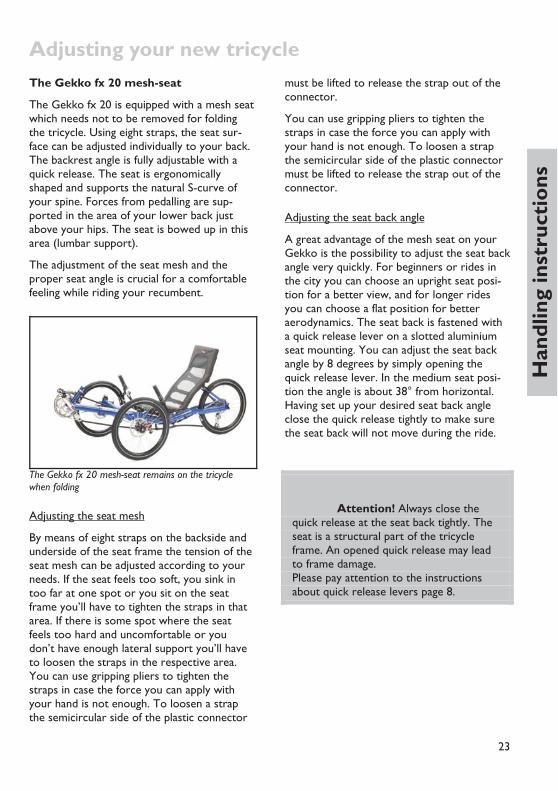
The Gekko fx 20 mesh-seat
The Gekko fx 20 is equipped with a mesh seat which needs not to be removed for folding the tricycle. Using eight straps, the seat sur-face can be adjusted individually to your back. The backrest angle is fully adjustable with a quick release. The seat is ergonomically shaped and supports the natural S-curve of your spine. Forces from pedalling are sup-ported in the area of your lower back just above your hips. The seat is bowed up in this area (lumbar support).
The adjustment of the seat mesh and the proper seat angle is crucial for a comfortable feeling while riding your recumbent.
The Gekko fx 20 mesh-seat remains on the tricycle when folding
Adjusting the seat mesh
By means of eight straps on the backside and underside of the seat frame the tension of the seat mesh can be adjusted according to your needs. If the seat feels too soft, you sink in too far at one spot or you sit on the seat frame you’ll have to tighten the straps in that area. If there is some spot where the seat feels too hard and uncomfortable or you don’t have enough lateral support you’ll have to loosen the straps in the respective area. You can use gripping pliers to tighten the straps in case the force you can apply with your hand is not enough. To loosen a strap the semicircular side of the plastic connector
must be lifted to release the strap out of the connector.
You can use gripping pliers to tighten the straps in case the force you can apply with your hand is not enough. To loosen a strap the semicircular side of the plastic connector must be lifted to release the strap out of the connector.
Adjusting the seat back angle
A great advantage of the mesh seat on your Gekko is the possibility to adjust the seat back angle very quickly. For beginners or rides in the city you can choose an upright seat posi-tion for a better view, and for longer rides you can choose a flat position for better aerodynamics. The seat back is fastened with a quick release lever on a slotted aluminium seat mounting. You can adjust the seat back angle by 8 degrees by simply opening the quick release lever. In the medium seat posi-tion the angle is about 38° from horizontal. Having set up your desired seat back angle close the quick release tightly to make sure the seat back will not move during the ride.
Attention! Always close the quick release at the seat back tightly. The seat is a structural part of the tricycle frame. An opened quick release may lead to frame damage. Please pay attention to the instructions about quick release levers page 8.

Adjusting your new tricycle
24
The head rest
Both seat types can be equipped with a head / neck rest which is adjustable in height and an-gle.
To relax the muscles in your neck on long rides you can purchase a head / neck rest to mount on the seat frame. Its height and incli-nation is adjustable at the clamp. Wearing a helmet the headrest pad should be positioned under the lower helmet edge next to your neck. Adjust the inclination in a way that the headrest does just not touch your neck/head while riding. It may be necessary to cut the two tubes protruding the clamp on the under-side to prevent them from touching your back.
Use the long holes and the screw hidden un-der the cushion (BodyLink-seat) or the mounting clamp (ErgoMesh- and Gekko-seat) for setting up the correct position. (There is also a mounting clamp with quick-release lev-ers available.)
Attention! Do not push or carry your tricycle on the head rest, this may damage the head rest or the seat!

25
Han
dlin
g in
stru
ctio
ns
Adjusting to your size Adjusting the front boom
In order to adjust the leg length you have to move the front boom (the front part of the frame where the cranks are mounted) in the main frame.
Loosing the bolts to adjust the front boom.
Unscrew the bolts M8x35 under the main tube with a 6 mm Allen key. Take a grip on the front derailleur tube or both cranks and move the front boom further into the frame or pull it out while cautiously turning it.
Before you pull out the front boom shift the chain to the smallest chain ring and sprocket. Turn the cranks a little bit backwards while pulling. Thus the chain is not under tension.
Attention! After you have un-screwed the clamping bolts take them off and examine them for deformation. Lubri-cate threads and heads thoroughly. Then re-fit the bolts. If they don't turn easily you will have to replace the bolts.
Adjust the front boom in a way that your leg is fully extended when your heel (wearing flat shoes) is in the foremost position on the pedal. Experience shows that the pedal-to-
seat distance on a recumbent can be slightly longer than on a conventional bicycle.
While you are pedalling, the ball of your foot should be positioned above the centre of the pedal axle.
It is important that your leg is not fully straightened when the crank is in the fore-most position. If the distance is too long it is difficult to overcome this dead point, pedalling becomes uncomfortable and there is too much strain on the sinews of your feet and legs. If the distance is too short you may suf-fer from knee pain.
Danger! When you insert the front boom, the front boom and the inner wall of the tube must be totally free from grease, otherwise it will not clamp prop-erly and may turn while you are riding. This can result in serious accidents.
Adjust the front boom so that your knee will not be fully straightened when pedalling.

Adjusting to your size
26
Attention! When you move the front boom take care that its end does not damage any light cables that possibly come out of the main frame. Please inform your-self about the length of the front boom on your tricycle before you do any work. While moving the front boom you also have to move the light cables. The light ca-ble must never be stressed by pulling.
For riders with short leg length the front boom has to be cut by a bicycle mechanic, so it can be inserted maximum possible. It is im-portant to trim the end of the tube neatly.
The bare metal of the shortened tube end has to be protected against corrosion with a paint stick or wax spray.
The maximum insertion of the front boom is limited by possible heel cycle of the frame’s cross bar, depending on the rider’s shoe size. Please check before riding your tricycle that there is enough heel clearance. For shorter riders under 175 cm body height we recom-mend to use shorter cranks.
On the left underside of the front boom there is a fine line. Align this line with the sticker on the main tube’s front end right above the clamping bolts to adjust the bottom bracket axle to a horizontal position. Additionally, you can look beyond the bottom bracket shell at the rear wheel axle and align the front boom parallel to it. Align your eyes with the bottom bracket axle and not the front derailleur tube. Then sit down on your tricycle and check the position.
Attention! The minimum inser-tion depth of the front boom into the main frame is 8 cm (3 1/5"). The end of the front boom must not be visible in the clamping slot when you look at the main frame from below, since this may result in a damage of the frame.
The rear end of the front boon must never be visible in the clamping slot.
Tighten the bolts with a torque wrench (tightening torque 14 – 16 Nm). On your first ride check whether there is sufficient clamp-ing.
The plastic bush between front boom and main frame must be visible at all time.

Adjusting to your size
27
Han
dlin
g in
stru
ctio
ns
Danger! There must be a bush-ing (a slotted tube of plastic with edges to the front and the clamping slot) in the main frame’s front boom hole that is glued in the frame. This bush ensures safe clamping of the front boom and protects the paint. It is important to take care that this bush is always visible at the front end of the main frame. The lower slot has to be aligned in coincidence with the slot in the main frame. If this bush is missing or moved to the back of the tube while inserting the front boom, safe clamping is no longer guaranteed, even if it seems to be the case at first glance. If the front boom is not clamped properly it may turn and lead to a fall. A missing or misaligned bush will lead to frame damage.
Danger! If the bolts are tight-ened too much or bent, the screw or the frame can break! If the clamping is insuffi-cient the front boom can turn during a ride which may cause your feet to slip from the pedals and lead to injuries.
After moving the bottom bracket tube your dealer has to adjust the chain length. By de-fault your recumbent tricycle comes with a very long chain so the adjustment range of the tricycle can be fully used without the need to lengthen the chain.
After the basic adjustment of the leg length done by your dealer before handing over the tricycle, the chain has to be shortened so that the derailleur cage is not fully turned forward while shifting on the largest chain ring in front and the smallest sprocket behind. The derail-leur must still be able to compensate a length change of the chain of at least 4 cm (1 1/2"). In
order to choose the right chain length, please consult the manual of the derailleur manufac-turer.
Danger! After the chain has been shortened it must be closed with a special closing link or a chain riveting tool that expands the rivet while riveting (i.e. ROHLOFF-Revolver). A poorly joined chain may break and thus lead to damage or in-jury. Chain length adjustments or chain changes should be done by your bicycle mechanic.
We recommend to slightly readjusting the front boom every 3 months in order to pro-vide a slightly different position to your mus-cles and ankles. You might also find a more comfortable and more efficient riding position.
Check that there is at least a 5 cm (2") clearance be-tween the end of the chain tube and other parts of the drive train
A wrong adjustment may lead to pain in your knees and inefficient pedalling. In addition we recommend riding with a high pedalling ca-dence, which means to pedal fast and with lit-tle pressure. Pedalling with too much pressure may also lead to pain in the knees.

Adjusting to your size
28
Attention! Take care that the chain tubes have a clearance of at least 5 cm (2") to the rear derailleur and the front derailleur even under maximum ten-sion of the chain and make sure that the tubes are held tight in their fastenings. The front upper tube can be moved to the rear for length adjustment. Shorten the tubes if necessary. If the end of the chain tube gets in touch with the rotating chain rings it can be locked-up and destroyed. The chain tubes must be prevented from moving by a rubber tube over the retention spring.
Adjusting the length with front boom quick adjust
The front boom quick adjust is additional equipment for HP VELOTECHNIK recumbents that feature a telescopic front boom for leg length adjustment. It replaces the standard bolts of the front boom clamping by quick re-lease levers. Two pulleys provide chain length compensation while moving the front boom.
Routing of the chain over the idlers of the front boom quick adjust
The front boom must be clean and free from wax or tenacious remains of chain lube to make sure it can be easily slid in and out.
First, shift the chain to the largest chain ring and the largest sprocket to check the correct chain length.
Open both quick release levers. Slide the front boom into the frame or pull it out until you’ve reached the required frame length.
To slide the front boom in, grip the cranks and turn them against the tensioned chain. The force on the chain helps to move the front boom into the frame tube.
To pull the front boom out, grip the derailleur tube if available. If you pull at the cranks, you’ll have to turn them backwards at the same time, else the tensioned chain will balk the motion.
Moving the front boom is easier when turning it a little bit from side to side. When doing this, make sure the pulley bracket doesn’t scratch the frame and its lug won’t be bent. That’s why we recommend to only turn the front boom clockwise (and back afterwards) when looking from the front.
Align the bottom bracket axis horizontally when looking from the front. Close both quick release levers.
Move the chain to the smallest chain ring and the smallest sprocket. Check the chain length. The rear derailleur cage should not be com-pletely swivelled to the back to still apply ten-sion to the chain.
Please pay attention to the instructions about quick release levers on page 8.

29
Han
dlin
g in
stru
ctio
ns
Adjusting the handlebars A good setting for the handlebars
While riding you should allow your arms to rest in a relaxed position on the handlebars. Do not push or pull on the handlebars. If the handlebars turn in the stem clamping during the ride stop immediately and tighten the clamping screw of the handlebars. If the han-dlebars are not sufficiently clamped the han-dlebars or the stem may be damaged or deformed. In this case, safe clamping can no longer be guaranteed, not even with the cor-rect tightening torque, and handlebars and stem have to be replaced.
Attention! When getting on and off the tricycle, make sure to avoid pulling at the handle bars or stepping on the tie rods. To get off the tricycle, sit upright on the front seat edge and then stand up. Grip the front wheels or the seat back as an ex-tra support, not the handlebars. If you pull firmly at the handlebars, the steering mechanism can be damaged.
The handlebar on tricycle of the Scorpion series allows adjustment in width (1) and angle (2)
Setting the width and angle on Scorpion, Scorpion fx, Scorpion fs 20, Scorpion fs 26 /S-Pedelec /Enduro, Scorpion plus 20 /plus 26
The handlebar consists of two parts. They are mounted to the stem by a slotted clamp on each side. The adjustment range in width is 3.5 cm on each side, giving a total range of 7 cm (aprox. 2 ¾").
Most riders are comfortable with an 85° angle so that the bent grips point upwards and slightly forward. The more upright the grip position and the narrower the handlebar width, the larger the minimum possible turn-ing circle as the handlebars touch your legs or the seat earlier.
In order to change the angle or the width, loosen the screws of the stem/handlebar clamping. Move the handlebars until they are in your favourite position. Tighten the clamp-ing screws with 8 – 10 Nm. Check the cor-rect clamping of the handlebars by sitting down on your tricycle and pulling the handle-bars. The handlebars must not turn in the stem.
Danger! If the handlebar grips are adjusted pointing too far forward or too wide, your hands or the brake levers can touch the front wheels or mudguards when cornering sharp, leading to injury. Make sure you have at least 5 cm (2“) clearance between brake levers and front wheels / mudguards at all steering angles.
Adjusting the handlebars
30
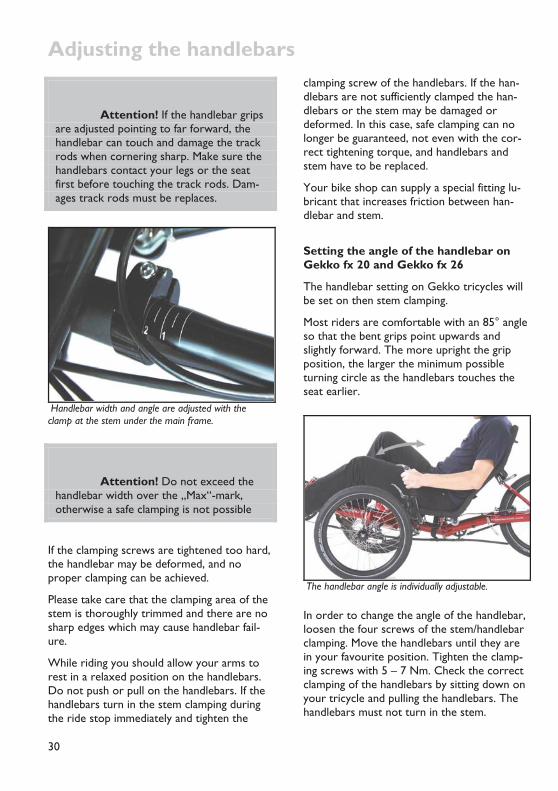
Attention! If the handlebar grips are adjusted pointing to far forward, the handlebar can touch and damage the track rods when cornering sharp. Make sure the handlebars contact your legs or the seat first before touching the track rods. Dam-ages track rods must be replaces.
Handlebar width and angle are adjusted with the clamp at the stem under the main frame.
Attention! Do not exceed the handlebar width over the „Max“-mark, otherwise a safe clamping is not possible
If the clamping screws are tightened too hard, the handlebar may be deformed, and no proper clamping can be achieved.
Please take care that the clamping area of the stem is thoroughly trimmed and there are no sharp edges which may cause handlebar fail-ure.
While riding you should allow your arms to rest in a relaxed position on the handlebars. Do not push or pull on the handlebars. If the handlebars turn in the stem clamping during the ride stop immediately and tighten the
clamping screw of the handlebars. If the han-dlebars are not sufficiently clamped the han-dlebars or the stem may be damaged or deformed. In this case, safe clamping can no longer be guaranteed, not even with the cor-rect tightening torque, and handlebars and stem have to be replaced.
Your bike shop can supply a special fitting lu-bricant that increases friction between han-dlebar and stem.
Setting the angle of the handlebar on Gekko fx 20 and Gekko fx 26
The handlebar setting on Gekko tricycles will be set on then stem clamping.
Most riders are comfortable with an 85° angle so that the bent grips point upwards and slightly forward. The more upright the grip position, the larger the minimum possible turning circle as the handlebars touches the seat earlier.
The handlebar angle is individually adjustable.
In order to change the angle of the handlebar, loosen the four screws of the stem/handlebar clamping. Move the handlebars until they are in your favourite position. Tighten the clamp-ing screws with 5 – 7 Nm. Check the correct clamping of the handlebars by sitting down on your tricycle and pulling the handlebars. The handlebars must not turn in the stem.

Adjusting the handlebars
31
Han
dlin
g in
stru
ctio
ns
If the clamping screws are tightened too hard, the handlebar may be deformed, and no proper clamping can be achieved.
Danger! If the handlebar grips are adjusted pointing too far forward or too wide, your hands or the brake levers can touch the front wheels or mudguards when cornering sharp, leading to injury. Make sure you have at least 5 cm (2“) clearance between brake levers and front wheels / mudguards at all steering angles.
Handlebar width is adjusted at the stem clamp under the seat.
Danger! Please take care that the clamping area of the stem is thoroughly trimmed and there are no sharp edges which may cause handlebar failure.
Adjusting the cable length
You can make smaller adjustments by moving the cables in their guides at the frame and the stem, so there is enough clearance for all movements. If this is not the case you will
have to have your specialist dealer shorten the cables or replace them by longer ones.
Attention! After having adjusted the handlebar position you have to read-just the length of the brake cables and shifter cables. The cables have to run smoothly without any sharp turns and they should not be bent sharply or stretched when the handlebar is at maximum angle. Also avoid large bows that could be caught up by the front wheels or other parts or touch objects under your tricycle.
Cover all contact areas where cables move and touch the frame with sturdy transparent tape. This protects the paint against scratching and wear.
Handlebar grips
The grips on the handlebar are susceptible to wear and tear. Have your grips replaced by your bike shop once they don't feel comfort-able any more. The grips always need to be attached firmly to the handlebar.

32
Folding Taking off the seat
First step when folding a tricycle out of the Scorpion family, the seat needs to be re-moved.
Open all three quick release levers of the seat mountings: Unscrew the nut of the upper seat quick release approximately 4 turns. Turn the quick release levers of the middle and lower seat quick release counter clockwise ap-proximately 4 turns.
With a water bottle mounting installed, space is limited and it may be easier to hold the quick release lever and turn the flat nut on the right side (chain side) of the seat mount-ings with a 5 mm Allen key.
Pull the lower seat half out of its mountings, then the upper seat half. After dismounting the seat tighten the quick release again to the quick release axle from bending when the folding buffer touches the frame.
Attention! When storing the seat, please take care not to bend or break the seat mountings. Protect the edges of the seat mountings with padding to avoid scratching other objects with the seat mountings.
Folding of Scorpion, Scorpion fx, Scor-pion fs 20
Folding the frame
The folding hinge features a snap-in function. It makes folding easier and prevents the frame from folding even when the quick release is not fastened.
To fold the frame, stand in front of the main frame’s cross tube and look to the rear wheel.
Grab the quick release lever on top of the folding hinge (1) and pull it upwards. Swivel the lever until it touches the front frame part.
Use your right hand to pull the whole hinge upwards a little bit. At the same time press the securing tab (2) downwards with your thumb. Now lower the frame to open the folding hinge. Lower the frame until the pro-tection plate below the stem touches the ground.
Quick release lever (1) and securing tab (2) of the folding hinge
The chain tubes are connected by a flexible rubber joint positioned in the area of the fold-ing hinge. Make sure all cables and electric wires are long enough to allow proper folding.
Grab the rear frame part and swivel it to the front. The strap mounted to the seat tube must be inserted into the fastener mounted under the left crossbeam. Press the frame parts together until the rubber bumper at-tached to the seat tube touches the front frame part.
Taking off the front wheels
To achieve an even smaller package, you can take off the front wheels (see page 56). In this case you will also have to remove the front mudguards (see page 83).

Folding
33
Han
dlin
g in
stru
ctio
ns
Unfolding
To unfold and reassemble your tricycle, please follow the steps above in the opposite order. Make sure that after unfolding the quick re-lease lever rests on the front frame part. Else the snap-in mechanism will not work prop-erly.
Lift the folding hinge until the securing tab snaps in. Now close the quick release lever until it touches the rear frame part.
Danger! Before riding your tri-cycle, make sure the quick release is se-curely closed. The securing tab must be locked and the quick release lever must be laying on the rear frame part. Cables or wires must run free. The handlebar must turn easily and freely. All seat quick re-leases must be closed properly. Please pay attention to the instructions about quick release levers on page 8.
Folding the Scorpion fs 26 /Enduro /S-Pedelec, Scorpion plus 20 /plus 26
Folding the frame
Attention! Close upper quick release lever after removing the seat! Oth-erwise there is a risk to damage the axis quick release lever that carries the folding buffer.
The folding hinge features a snap-in function. It makes folding easier and prevents the frame from folding even when the quick release is not fastened.
Before folding shift your gears to smallest chainring and smallest sprocket. This will make folding easier.
Attention! If the gear system is not in smallest sprocket and smallest chainring the chain may be tightened so far that the rear derailleur can be damaged or the derailleur hanger can be torn.
To fold the frame stand behind the main frame’s cross tube and look to the left front wheel. Grab the quick release lever on the left side of the frame and pull it upwards and to the fore.
Opening the quick-release lever of the folding hinge
Swivel the lever past the lower seat quick re-lease until it touches the front frame part.
Use your right hand to pull the whole hinge upwards a little bit. At the same time pull away the securing tab from the hinge with your fingertips to open the folding hinge. If necessary push a little bit from the side where the quick release lever is situated.

Folding
34
Securing tap on a Scorpion plus 26
Opening the securing tab of the folding hinge
While folding take care that the handlebars are in a position where they will not crash into the frame rear part. On tricycles with long handlebars, please use the quick release at the stem clamp to fold the left handlebar side to the front (see page 29). On Scorpion plus 20 and Scorpion plus 26 fold the handle-bar to the back.
Make sure that after unfolding the frame the handlebar is set back into its original position and the quick release lever is closed com-pletely.
Move the chain tubes besides the folding hinge
Attention! Make sure all cables and electric wires are long enough to allow proper folding. The chain tubes are con-nected by a flexible rubber joint positioned in the area of the folding hinge.
Locking the frame with the hook-and-loop strap on the cross tube
When the tricycle is folded, the frame must be protected against unwanted unfolding. To do so the Velcro strap attached to the seat tube must be stripped away. Attach it to the cross tube where its counterpart is posi-tioned. Always apply the Velcro so that the buffer is pulled to the centre of the tube. Re-member to close the quick release lever with

Folding
35
Han
dlin
g in
stru
ctio
ns
the folding buffer tightly. Otherwise, the axis may be distorted when folding.
Taking off the front wheels
To achieve an even smaller package, you can take off the front wheels (see page 56). In this case you will also have to remove the front mudguards (see page 82)
Unfolding
To unfold and reassemble your tricycle, please follow the steps above in the opposite order.
Make sure that after unfolding the quick re-lease lever rests on the front frame part. Else the snap-in mechanism will not work prop-erly.
Lift the folding hinge until the securing tab snaps in noticeably. Some momentum will be helpful. Now close the quick release lever un-til it touches the rear frame part.
Mounting the seat
As first step merge the lower seat connection sheets with their respective connection tube on the frame. Align the seat to the frame cen-ter. Then slide the middle and upper seat connection sheets with their openings on the respective quick release. Be careful to not cause any paint damage. With the BodyLink-seat it is possible to first push in the middle seat connection and then the upper because of its flexibility. In case the seat can not be mounted easily check the quick releases are loosened enough (if necessary unscrew the nuts a little bit more). It may be helpful to punch the seat with your hand to properly fit the seat to the tricycle. Close the quick re-
leases. Please refer to the hints given on page 8.
Danger! Before riding your tri-cycle, make sure the quick release is se-curely closed. The securing tab must be locked and the quick release lever must be laying on the rear frame part. Cables or wires must run free. The handlebar must turn easily and freely. All seat quick re-leases must be closed properly. Please pay attention to the instructions about quick release levers on page 8.

Folding
36
Folding the Gekko fx 20 and Gekko fx 26
Folding with D.F.F.-move
Thanks to the Dual-Flat-Fold (D.F.F.) technol-ogy, your Gekko fx 20 or Gekko fx 26 folds from a comfortable touring tricycle to a com-pact package within 10 seconds. Then it can be stored upright or towed on its integrated rollers.
To fold the tricycle stand on the right side next to the seatback.
1. Open the quick release behind the seat and swivel the seatback to the front.
2. Take the Velcro strap off the second strap and apply it to the soft Velcro under the cross tube to secure the seatback in its position.
3. Open the quick release at the folding hinge. Release the safety bolt against spring pressure. Slightly open the folding hinge. Swivel the quick release lever to the upside so that it is held in an upright position by the sheet metal.
4. Grab the main tube with your right hand in front of the seatback (knuckles facing to the right, away from the frame). Push a little bit to prevent the folding hinge snapping in. Grab the left seat stay with your left hand from the upside (knuckles facing the rear wheel).
5. Now do the D.F.F.-move: Lift the frame, turn it sideways and fold the rear wheel transversely below the frame in a smooth mo-tion. Make sure the folding buffer passes through the long hole in the stem under part to lock the steering. The buffer must not crash on the stem under part as the sheet metal may be deformed.

Folding
37
Han
dlin
g in
stru
ctio
ns
6. Push the frame together until you can hear the locking sheet metal snaps in.
7. Place the folded Gekko fx 20 or Gekko fx 26 upright on the integrated rollers and the buffer inside the folding hinge.
Attention! Don’t turn the cranks after folding. To pull the folded tri-cycle you have to pull it at the frame, not at the cranks or pedals. Else the chain roller or the chain retention hook may be damaged.
Unfolding with D.F.F.-move
To unfold the Gekko fx 20 or Gekko fx 26 stand next to the left front wheel.
1. Grab the left seat stay with your left hand (knuckles facing to the rear wheel). Slide your right hand between main tube and seatback and push the locking sheet metal's tongue away from the seatback. At the same time slightly open the frame with the left hand.
2. Grab the main tube directly in front of the seatback (knuckles facing away from the tricy-cle).
3. Do the reverse D.F.F.-move: Lift the pack-age with drive and pull both frame parts away from each other. Push the folding hinge away from your body. The securing bolt snaps in. Turn the tricycle outward during the move and put it down on the floor.

Folding
38
4. Close the folding hinge quick release.
5. Release the Velcro under the cross tube and put it back on the seat strap.
6. Rearrange the seatback to your desired po-sition and close the quick release.
Taking off the front wheels
To achieve an even smaller package, you can take off the front wheels (see page 56). In this case you will also have to remove the front mudguards (see page 83).

Folding
39
Han
dlin
g in
stru
ctio
ns
Folding on the floor
Alternatively, the Gekko fx 20 or Gekko fx 26 can be folded on the floor:
1. Open the quick release behind the seat and swivel the seatback to the front.
2. Take the Velcro strap off the second strap and apply it to the soft Velcro under the cross tube to secure the seatback in its position.
3. Turn the tricycle on the right front wheel.
Attention! Don’t rest the tricy-cle on the rear rack. It may become de-formed.
4. Open the quick release at the folding hinge. Release the safety bolt against spring pressure. Slightly open the folding hinge. Swivel the quick release lever to the upside so that it is held in an upright position by the sheet metal.
5. Swivel the rear part forward comfortably. Make sure the folding buffer passes through the long hole in the stem under part to lock the steering.
6. Push the frame together until you can hear the locking sheet metal snaps in.
7. Tilt the folded Gekko fx 20 or Gekko fx 26 sideways to make it stand upright on the on the integrated rollers and the buffer inside the folding hinge.
Unfolding on the floor
To unfold the Gekko fx 20 or Gekko fx 26, stand next to the rear wheel of the tricycle standing on its rollers.
1. Tilt the tricycle on the right front wheel.
2. Use your right hand to push the locking sheet metal's tongue downwards. Grab the seat stays with your left hand.
3. Swivel the rear part of the tricycle com-pletely to the right. The folding hinge’s secur-ing bolt snaps in.
4. Tilt the tricycle back on its wheels
5. Close the folding hinge quick release.
6. Release the Velcro under the cross tube and put it back on the seat strap.
7. Rearrange the seatback to your desired po-sition and close the quick release.

Folding
40
Danger! Make sure the folding hinge is properly closed. The safety bolt must be snapped in correctly and the quick release fastened tightly.
Attention! Always tightly close the quick release at the seat back. The seat is a structural part of the tricycle frame. An opened quick release may lead to frame damage. Please pay attention to the in-structions about quick release levers on page 8.

41
Han
dlin
g in
stru
ctio
ns
Lighting system Lighting systems for bicycles
If you want to ride your tricycle on public streets, it must be equipped with a legal light system. Do not only use your lights in the dark but also in the twilight of dusk and dawn. Due to laws and regulations the brightness of bicycle lights may be considerably lower than that of other vehicles. Therefore always keep in mind that other road-users may only see you very late or not at all.
For the bicycles, HP VELOTECHNIK offers a dy-namo light systems with a tire dynamo or a hub dynamo. The S-Pedelec lighting system is powered by the propulsion system’s accumu-lator, which is also available for bicycles with GO SWISSDRIVE pedelec system.
Both light systems come with strong LEDs for headlamp and rear light. The LEDs last con-siderably longer (approx. 100.000 working hours) than a light bulb. For your safety the light system has a parking light system both at the front and at the rear light, which makes the LEDs shine on approximately 10 minutes after you have stopped riding. The electronic system is maintenance free. Because of the capacitors used you don't have to worry about batteries.
The cables and the contacts can be affected by corrosion or mechanical damage. Therefore, check the light system before every ride.
Tire dynamo
You turn on the light system with the tire dy-namo at the rear wheel by unlocking the swivelling dynamo. For this purpose you press the red button at the dynamo until it moves towards the rear wheel. To turn the light off, swivel the dynamo back to its initial position by hand.
Danger! Do not try to move the dynamo while riding, your hands can be caught in the wheel and be injured! To turn the light system on or off stop riding, get up from your tricycle and only then move the dynamo.
Danger! The dynamo must al-ways be safely fastened to the bracket at the frame, so that it can not turn. If the screws come loose the dynamo can get caught in the spokes and block the rear wheel – danger of a serious fall! Always check the position and secure attachment of the dynamo before a ride.
You can adjust the pressure of the dynamo against the wheel with the turning knob at the side. The pressure is right when the dynamo wheel just does not slip at the wheel, if the light flickers, the pressure is too low and you have to increase it. The dynamo should be positioned in a way that the extension of the dynamo axle points through the center of the wheel. Take care that the dynamo is mounted safely and can’t be turned. Worn dynamo wheels can be exchanged. Please ask your specialist dealer.

Lighting system
42
For the hub generator light system and battery powered light systems on pedelecs and Scorpion fs 26 S-Pedelec, there is an integrated switch at the front light to turn the lights on and of.
You switch on the tire dynamo by pressing the red but-ton. To switch off the dynamo move it away from the wheel.
Hub dynamo
The lighting system with a hub dynamo is switched on electrically. For this purpose you will find a switch on the back of the rear light with three labelled switch positions. With the switch you can turn the lighting system ON, OFF or set it to SENSOR. In the SENSOR po-sition a twilight sensor in the lamp turns the lighting system on and off automatically de-pending on the brightness of the environment.
The SON hub dynamo is highly efficient and works silently. When the dynamo is turned off it has a very low turning resistance. Although you can feel the single poles of the used per-manent magnets very distinctly when turning it by hand the real rolling resistance is minute. (The loss is below 1 W at 15 km/h / 9,5 mph.)
SON dynohub

Lighting system
43
Han
dlin
g in
stru
ctio
ns
Lighting system of Scorpion fs 26 S-Pedelec
The Scorpion fs 26 S-Pedelec lighting system is supplied with 12 V DC out of the propul-sion system’s accumulator.
To turn the system on and off there is a switch at the back of the headlight with two positions ON and OFF. Additionally, there is a legally required position light mounted under the headlight. It is switched on and off to-gether with the headlight.
The S-Pedelec rear light has braking light and license plate illumination
Danger! Do not switch the lights on or of while driving. There is a serious danger of accidents!
Only ride your S-Pedelec with accumulator installed. Without accumulator lighting system and brake light are out of function. The light-ing equipment according to S-Pedelec regula-tion is not sufficient to use the S-Pedelec as a bike according to German StVZO rules even during daytime.
Please pay attention to your countries regula-tions for public traffic!
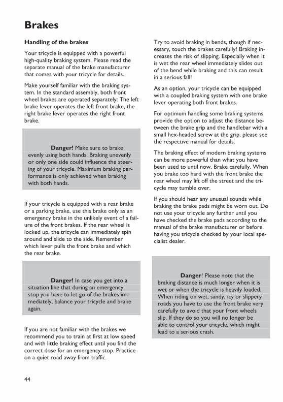
44
BrakesHandling of the brakes
Your tricycle is equipped with a powerful high-quality braking system. Please read the separate manual of the brake manufacturer that comes with your tricycle for details.
Make yourself familiar with the braking sys-tem. In the standard assembly, both front wheel brakes are operated separately: The left brake lever operates the left front brake, the right brake lever operates the right front brake.
Danger! Make sure to brake evenly using both hands. Braking unevenly or only one side could influence the steer-ing of your tricycle. Maximum braking per-formance is only achieved when braking with both hands.
If your tricycle is equipped with a rear brake or a parking brake, use this brake only as an emergency brake in the unlikely event of a fail-ure of the front brakes. If the rear wheel is locked up, the tricycle can immediately spin around and slide to the side. Remember which lever pulls the front brake and which the rear brake.
Danger! In case you get into a situation like that during an emergency stop you have to let go of the brakes im-mediately, balance your tricycle and brake again.
If you are not familiar with the brakes we recommend you to train at first at low speed and with little braking effect until you find the correct dose for an emergency stop. Practice on a quiet road away from traffic.
Try to avoid braking in bends, though if nec-essary, touch the brakes carefully! Braking in-creases the risk of slipping. Especially when it is wet the rear wheel immediately slides out of the bend while braking and this can result in a serious fall!
As an option, your tricycle can be equipped with a coupled braking system with one brake lever operating both front brakes.
For optimum handling some braking systems provide the option to adjust the distance be-tween the brake grip and the handlebar with a small hex-headed screw at the grip, please see the respective manual for details.
The braking effect of modern braking systems can be more powerful than what you have been used to until now. Brake carefully. When you brake too hard with the front brake the rear wheel may lift off the street and the tri-cycle may tumble over.
If you should hear any unusual sounds while braking the brake pads might be worn out. Do not use your tricycle any further until you have checked the brake pads according to the manual of the brake manufacturer or before having you tricycle checked by your local spe-cialist dealer.
Danger! Please note that the braking distance is much longer when it is wet or when the tricycle is heavily loaded. When riding on wet, sandy, icy or slippery roads you have to use the front brake very carefully to avoid that your front wheels slip. If they do so you will no longer be able to control your tricycle, which might lead to a serious crash.
Brakes
45
Han
dlin
g in
stru
ctio
ns
Danger! Always make sure that the disc or rims and brake pads are free of oil and grease. If these parts are dirty please do not use your tricycle. You can clean oily discs with alcohol or a special spray. Oily brake pads have to be replaced. If you are in doubt, please have your spe-cialist dealer maintain your braking system. Riding with contaminated braking systems can result in serious accidents!
Danger! Never touch neither the brake disc nor the brake caliper after long braking as this may cause serious in-jury (risk of burns).
Danger! Disc brakes can over-heat on long down hill rides, fade and fail! On down hill rides, do not brake con-stantly, but in several intervals with higher pressure. If you notice that the brake power starts to fade, stop immediately and let your brakes cool down.
New braking systems, new brake pads and new brake discs need a break-in period to achieve maximum brake power. This period lasts for about 30 – 40 stops from about 30 km/h (20mph), which should be done in a safe area without traffic.
Parking brake
Always secure your tricycle against rolling away when parked.
In the standard assembly, the brake levers are equipped with a parking brake-button that
locks the pulled lever. To release the parking brake, pull the brake lever.
As an option the tricycle can be equipped with a parking brake that is operated with a thumb-shifter mounted at the handlebar. It is connected with a V-brake at the rear wheel. Make sure to fully open the parking brake be-fore you start riding.
Maintenance of the brakes
Attention: Always read the brakes manufacturers manuals carefully be-fore doing any maintenance or repair jobs on the brakes! Here you can find detailed information and pictures of how to do it!
The brake pads suffer from wear due to fric-tion and have to be exchanged then. Depend-ing on riding conditions, they can last between a few hundred up to several thousand kilome-tres. Please read the manual of the brake manufacturer carefully.
Check before every ride:
• that the braking system does not have any damages or leaks by activating the lever, holding it and checking the hose connec-tions for possible leaks.
• that the brake lever pressure is ok by pull-ing the lever and ensuring that full braking performance is achieved before the lever touches the handlebar. If this is not the case, adjust the cable or change the brake pads, for hydraulic disc brakes pull the lever several times (pump) until it feels firm.
• check the hydraulic braking system for the correct pressure by pulling the lever, hold-ing the pressure and checking the hose connections, bleeding screw and compen-sating tank for possible leaks.

Brakes
46
Cable operated (mechanical) brakes
The brake pads of your brakes are worn when you can pull the lever further and fur-ther to the handlebar before the pads touch the rim.
To compensate the wear of the brake pads you can tighten the cable with the adjuster barrel where the cable touches the brake lever. First loosen the locknut, then unscrew the barrel so far that the wheel still turns barely not touching the pads, hold the barrel and tighten the locknut again towards the brake lever housing. Take care that the bar-rel’s slot points downwards to prevent mois-ture from entering.
Keep the brake cable clean where it is not protected by the cable housing. Due to the mounting position of the brake lever, mois-ture and dirt may enter the cable and cause drag and excessive wear. Lubricate the ends of the cable to protect against moisture.
Attention! Damaged cables with single wires sticking out have to be re-placed immediately. Otherwise your brak-ing system may fail
Danger! Please take care that the cable ends are always protected with a cap. Always keep the cables shortly trimmed. Leaving too much cable extend-ing past the cable anchor can result in the cable catching in the rotor or wheel caus-ing the wheel to lock up.
Mechanical disc brakes
To readjust the brake pads you have to use the big red knobs on each side of the brake
caliper. Adjust the inner and the outer pad evenly. In case you are not sure, have this ad-justment work done by a qualified bicycle me-chanic.
Check your brake pads frequently as ex-plained in the manual supplied by the brake manufacturer. Worn brake pads, oily or dam-aged pads must be replaced immediately by a qualified bicycle mechanic.
Hydraulic brakes
Hydraulic brakes on HP VELOTECHNIK tricycles use low viscosity mineral oil that, contrary to DOT brake fluid used in cars, does not ab-sorb water. Thus, you don't have to change the oil. Please read the brake manufacturer’s manual that comes with the tricycle.
Danger! All maintenance work on the hydraulic system of your brakes may only be carried out by a qualified technician. In case these works are carried out without the required knowledge and skills the braking system might fail which can lead to a serious crash.
In case of a damaged hose or any leakage of oil always consult a qualified technician in a bike shop.
Hydraulic disc brakes
Hydraulic disc brakes feature a fully automatic pad wear adjustment. Brake pads and discs are subject to wear, therefore regularly check the thickness of your brake pads and discs and replace them if necessary. The minimum thickness of the brake pad is 1 mm, of the brake disc it is 1,7 mm. For further and more detailed information on your disc brake model
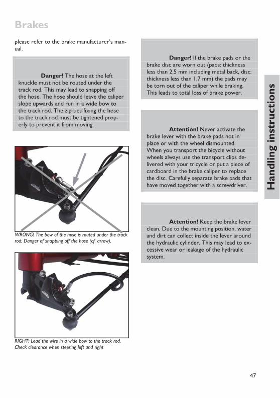
Brakes
47
Han
dlin
g in
stru
ctio
ns
please refer to the brake manufacturer’s man-ual.
Danger! The hose at the left knuckle must not be routed under the track rod. This may lead to snapping off the hose. The hose should leave the caliper slope upwards and run in a wide bow to the track rod. The zip ties fixing the hose to the track rod must be tightened prop-erly to prevent it from moving.
WRONG! The bow of the hose is routed under the track rod: Danger of snapping off the hose (cf. arrow).
RIGHT: Lead the wire in a wide bow to the track rod. Check clearance when steering left and right
Danger! If the brake pads or the brake disc are worn out (pads: thickness less than 2,5 mm including metal back, disc: thickness less than 1,7 mm) the pads may be torn out of the caliper while braking. This leads to total loss of brake power.
Attention! Never activate the brake lever with the brake pads not in place or with the wheel dismounted. When you transport the bicycle without wheels always use the transport clips de-livered with your tricycle or put a piece of cardboard in the brake caliper to replace the disc. Carefully separate brake pads that have moved together with a screwdriver.
Attention! Keep the brake lever clean. Due to the mounting position, water and dirt can collect inside the lever around the hydraulic cylinder. This may lead to ex-cessive wear or leakage of the hydraulic system.

48
Gear system and chainHandling of the gear system
With the gear system you can adjust the ped-alling frequency, i.e. the number of revolutions of the crank per minute, to the terrain and the desired speed.
Your pedalling frequency should stay between 80 – 100 revolutions per minute and not fall below 60 while going uphill. If necessary con-sult your local dealer and have him adapt the gear range to your style of riding.
Your recumbent tricycle comes standard with a derailleur gear or with an internal hub gear system. The following section refers to the derailleur gear system only. Please also refer to the manual of the gear manufacturer.
You operate the gear changer with the grip shifters or bar end shifters on the handlebars. The right lever for the rear derailleur has an index derailleur system that positions the chain always on the chosen sprocket, so that you don't have to "search" for the gears. The left barend shifter is not indexed so you have to adjust the front derailleur while shift-ing by slightly moving the shifter to stop the front derailleur from dragging against the chain while pedalling.
Riding a recumbent requires foresighted gear shifting. Before stopping you should timely change in a low gear to make it easy to start off again, without having to pedal heavily.
Attention! Under no circum-stances allow the tricycle to roll back while changing the rear gears, or try to pull the tricycle backwards when the gear shifter lever has been moved, as this will damage the rear derailleur.
You should only change the gears while you keep pedalling, smoothly and without applying
great force, all the time that the chain is mov-ing between the sprockets. Due to the long cables that expand under pressure and the housing that compresses under pressure it may be helpful for changing gears quickly to turn the bar end shifter a little bit farther than necessary to select a gear and turn it back to the indexed position once the chain has prop-erly shifted ("overshift").
When the chain length has been properly ad-justed you can choose every combination of front chain rings and rear sprockets to shift gears. However, it is useful to ride the lowest gears (the biggest rear sprocket) with the smallest chain ring, the middle gears with the middle chain ring and the highest (fastest) gears with the biggest chain ring. The setup of the chain rings and sprockets leads to an overlap of some gears. This means that different combinations of chain rings and sprockets can result in the same gear ratio. It would be possible to arrange a gear system so that double gears do not occur but this re-quires a lot of concentration when you shift gears while riding, since you will always have to change the rear sprockets as well as the front chain rings. If you would like to change the setup of your gears please consult your local dealer.
Danger! Practice shifting gears on a traffic-free street. In the course of this make yourself familiar with the functioning of the bar end shifters. Doing this in traffic could distract your attention from possible dangers.
Gear system and chain
49
Han
dlin
g in
stru
ctio
ns
Adjusting the gear system
Your dealer will adjust your derailleur gearing system carefully before handing over the tri-cycle. But during the first 300 kilometres (186 miles) of riding the cables can stretch, making the gear indexing imprecise. The chain then climbs only hesitantly onto the next sprocket.
Attention! Please read the man-ual of the gear system manufacturer care-fully before working on the gear system.
Adjusting the gear indexing for the rear derail-leur
Adjust the adjuster barrel where the shift ca-ble touches the rear derailleur. Do it in small steps of half a turn.
Check after each adjustment whether the chain moves smoothly up to the next larger sprocket. To do this, either turn the cranks by hand or ride the tricycle.
When the chain climbs up easily, you need to check that it still goes down easily onto the smallest sprocket. If necessary turn the ad-juster barrel a little more and then try shifting gears again.
Danger! If the chain shifts over the smallest or the biggest sprocket you have to readjust the end-limit adjusters of the rear or the front derailleur. Incorrect adjustment can lead to the chain coming off, getting stuck or damaging the spokes, which may result in serious falls. The ad-justment of the end-limit adjusters is a job for a professional bicycle mechanic.
Danger! If the tricycle falls over, the derailleur or its mounting can be bent which results in a change of the derailleur movement range. Check the movement range and have it readjusted by your bicy-cle mechanic, if necessary.
All moving parts of the gear system are af-fected by wear. Cleaning and lubricating these parts frequently can prolong the life of these parts. However, they will have to be replaced once worn out.
The cables have to be checked, cleaned and serviced regularly. Expect more wear and corrosion when the tricycle is often parked outside in bad weather conditions.
Attention! Damaged cables that show for example single wires have to be changed immediately. Otherwise they may damage your gear system. Take care that the ends of the cables are protected with fitting caps.

Gear system and chain
50
Chain
The chain is a wearing part that has to be lu-bricated regularly and to be changed at signs of excessive wear and tear. The amount of wear depends on maintenance and care as well as on the circumstances of your ride (rain, dirt, salt). Regular cleaning and lubricat-ing can increase the chain’s lifetime, neverthe-less the chain has to be changed when its wear limit is reached.
Lubricating the chain
Diligent lubrication is important. The chain of your recumbent tricycle is approximately 2.5 times longer than a standard bicycle chain (ap-proximately 3.8 m). But it also lasts longer since a chain only wears while bending at the sprockets and the chain rings.
Use good chain oil that won't leave a sticky film on the chain. The chain oil must not con-tain any aggressive chemical substances that might affect the surface of the chain tubes or chain idler.
Specialist stores sell biodegradable lubricants. HP VELOTECHNIK recommends a DryLube-type lubricant. This lubricant is purely based on PTFE (Teflon) that keeps the chain clean and dry. This way dirt simply falls off and the tubes always stay clean.
It is important that you clean the chain with a cloth before lubricating. Otherwise the fresh oil washes the dirt that clings to the chain into the gaps and the bushings where the dirt causes heavy wear.
Do not use any solvents to clean the chain! The solvent washes the oil off the bearing parts, stays there and dilutes the fresh oil so that a sufficient lubrication is not guaranteed. If you have treated the chain with a solvent you will have to heat it up with a hot air gun or boil it in chain grease.
Danger! Take care not to pour any oil on the rims, brake discs or the tires. The braking system could fail or the tires could slip away suddenly. The oil af-fects the rubber of your tires and can dam-age it. While lubricating cover the surrounding area.
An effective protection against corrosion is crucial for a long chain life. Some minutes af-ter you have oiled the chain rub it with a cloth to remove superfluous oil from the outer sur-face. Wax the chain thoroughly with a wax spray. The wax keeps off water, protects from corrosion and makes dirt fall off easily.
If the chain has become wet after riding in the rain you should put your bicycle in a dry and heated room, and every day you should turn the crank and so move the chain until it is dry again. Otherwise it is difficult for the moisture in the tubes to evaporate which may lead to corrosion at the chain.
Replacing the chain
The chain is one of the parts of the tricycle that will wear out. This shows in a stretching of the chain. Worn out chains do not fit the sprockets and chain rings any more and wear them away very quickly.
Check the chain for lengthening regularly. For this purpose, try to remove the chain from the chain ring. The chain may come off to a maximum of 5 mm. For a more precise read-ing you can buy a chain measurement gauge in your bicycle shop.
Only use chains that are suitable for the gear system of your tricycle. Otherwise a precise gear shifting is not guaranteed any more. Please consult your dealer on this topic. He will also assist you in checking your sprockets and chain rings. A new chain does not fit a
Gear system and chain
51
Han
dlin
g in
stru
ctio
ns
worn sprocket or chain ring. We recommend rust resistant Rustbuster-chains from KMC with smoothly rounded edges. They also pro-vide a good gear changing performance.
Attention! When you change the chain take care that the new chain does not show any sharp edges or burrs.
HP VELOTECHNIK delivers spare chains by the meter via your dealer. For this purpose please indicate the exact length of your chain or or-der it a little bit longer if you want to be sure it fits. You will need approximately 3,8 m of chain.
The chain length has to be fitted so that the arm of the derailleur is not fully stretched when you shift on the big chain ring in front and the big rear sprocket. The derailleur must still be able to compensate a shortening of the chain by 4 cm. Please also see the manual of the derailleur manufacturer on the choice of the correct chain length.
Attention! The chain has to be closed with a special joining link or a chain riveting tool that expands the ends of the rivet while riveting (ROHLOFF revolver). A poorly joined chain may break, you can come off the pedals and fall. If you are in doubt please have adjustments of the chain length or the changing of the chain be done by your bicycle mechanic.
Take care that the joining link is not bigger in size than the other chain links to avoid irregu-lar chain sounds. We recommend the joining
links by KMC. Every time you change the chain you also have to apply a new joining link.
Make sure that any chain links in the chain are not stiff, as this can cause some annoying and not obvious problems with the gear system.
Make sure that you have not twisted the chain 180 degrees before joining it back together.
Chain tubes
The chain protection tubes are made of a long lasting plastic that features very low friction, slow wear and good noise damping. The tubes protect your clothes against the chain oil as well as the chain against dirt from the road. The upper tubes are fastened with an inter-changeable retention spring, the lower tube runs through an adjustable clip.
The tubes are worn by the chain and have to be cut at the ends and expanded again (or ex-changed) after 3.000 – 5.000 km approxi-mately, depending on the chain type and the overall riding condition. You can extend this maintenance interval by turning the tubes by a quarter turn from time to time so that they do not keep wearing out in the same place.
The intensity of the wear depends mainly on the chain type. Please see also the instructions on "Chain" on page 51. In order to perform any work at the chain tubes you'll have to open the chain and finally close it again. Please see the instructions on "Chain" on page 38.
The distance of the upper chain tube to the chain wheel can be adjusted by sliding the tube in the retention spring. It must be se-cured with the rubber tube over the spring.

Gear system and chain
52
Danger! Take care that the chain tubes keep at least a 5 cm distance to the rear and front derailleur when the chain is stretched to the maximum, and that the tubes are well fastened. If necessary you will have to shorten the tubes. If the end of a chain tube gets into the rotating parts of the drive train the drive train can be blocked and the chain tubes may be de-stroyed.
Danger! The rear ends of the upper chain tube have to be secured against moving with a tight rubber tube over the retention spring. Without the rubber tube the chain tube may be dragged forward into the turning chain roller or chainring and thus be damaged by the chain.
Danger! Check the chain tubes frequently if they are damaged or defective. Replace defective chain tubes immediately. If the chain tubes are worn in the area of the retention spring or tube mountings, the chain will touch the retention spring, leading to failure of the spring and mount-ings. As a result, the chain tube can get into the drive train and block it!
Expanding the tube ends
The ends of the tubes are expanded like a trumpet so that the chain can enter smoothly without friction and without making noises.
When the ends are worn out you can renew them by expanding them again. Remove the
chain by opening the power link or open it with a special chain riveting tool. Cut the worn part of the tube exactly perpendicular with a sharp knife.
Heat the last 5 – 10 mm at the end of the tube with a gas burner, a hot air gun, or a candle and turn it permanently until the col-our of the utmost edge turns from a dull black to a shiny black. Now you expand the end with a proper tool, e.g. the rounded grip of a screwdriver. Quench the expanded end im-mediately with cold water. Take care that the tubes don't catch fire. At any rate work in a place with sufficient ventilation.
If the tube is too short after you have cut it so that there is not enough protection anymore it has to be replaced. You can buy spare tubes either as uncut tubes or already cut into the correct length, complete with retention spring from your specialist dealer.
Replacing the tubes
In order to exchange single parts in the upper chain tubes cut the old tube at the retention spring at the chain roller and pull the remain-ing part off the spring. Now move the smooth part of the new tube through the spring and rubber tube, then expand the tube end as de-scribed above.
Changing the complete upper chain protec-tion or the retention spring
Remove the bolt in the chain roller with an Allen key 6 mm. Take off the chain roller, the washer and the chain retention hook.
The end of the threaded tube in the frame is protected with a plastic tube. Take the reten-tion spring off this plastic tube and put on the new retention spring. Turn the spring so that the retention springs run under the spacer to the tubes and the wires lie between frame and chain tube; that way the spirals face outwards.
Gear system and chain
53
Han
dlin
g in
stru
ctio
ns
Push the bolt back through the chain roller, the washer and the chain retention hook, se-cure the thread with LOCTITE and tighten the bolt with 17 – 19 Nm. The recessed side of the chain roller has to face to the frame. Make sure the washer is placed between chain roller and plastic tube / frame.
Changing the lower chain tube
The chain tube is connected to the mounting plate by a rubber sleeve. For dismounting the chain tube, grab the sleeve on its rear end and pull it together with the chain tube to the rear. The rubber sleeves will release the rear tongue of the mounting plate then. Swivel the chain tube sidewards. Having done that pull the chain tube to the front to release the sleeve from the front tongue of the mounting plate. Replace the chain tube and mount it by following the above steps vice versa.
Chain roller
The chain roller guides the chain below the seat to the rear wheel and is an essential part of the HP VELOTECHNIK No Squat design. It ensures that the suspension is not influenced by pedalling.
Compared to other models the chain roller has a big diameter and it has a higher area in the middle to make the chain move as smoothly as possible. Due to this higher area the chain does not lie on the roller with its sharp edged links but with the bushes in the middle that work like small bushings. In addi-tion to a very low rolling resistance it also supports a quiet chain movement. A chain re-tention hook between the frame and the chain roller locks the roller at the bottom and keeps the chain on the roller when you pedal backwards.
Attention! If this chain retention hook is missing the chain may fall down. When you start pedalling then the chain roller, the seat or the frame may be dam-aged through the chain. Please consult your local specialist dealer in case this hook is missing.
The chain roller wears slowly and gradually shows a sprocket shape in the higher area in the middle. When this middle area is worn completely the links of the chain will run on the roller. In that case you will notice that the chain makes more noise while running and you should change the roller. You can pur-chase the plastic part without the bearing or the complete roller through your dealer.
Attention! The roller comes with two maintenance free sealed bearings. The bearings are exchangeable. Between the bearings there is a spacer that keeps the correct distance. If you forget to put in the spacer after you have dismounted the bearings they will be destroyed when you tighten the screw while remounting them.
The bearings must not be treated with a jet of water from a high-pressure cleaner or with solvents since this may destroy the sealings and remove grease from the bearings. If the bearings don't move smoothly anymore you'll have to replace them.

Gear system and chain
54
Chain roller, chain hook and chain tubes on Scorpion fs 26
Dismounting and mounting of the chain roller
To dismount the chain roller, the chain tubes need to be removed. See also hints on replac-ing the chain tubes (page 53)
The chain roller is mounted with a special high strength screw of the German strength grade 12.9 and it may only be replaced by a screw of the same type and strength.
The chain roller is not symmetrically shaped; the recessed side of the chain roller has to face to the frame, the flat (logo) side out-wards.
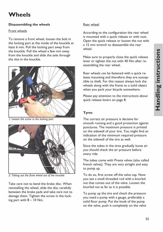
55
Han
dlin
g in
stru
ctio
ns
WheelsDisassembling the wheels
Front wheels To remove a front wheel, loosen the bolt in the locking part at the inside of the knuckle at least 6 mm. Pull the locking part away from the knuckle. Pull the wheel a few mm away from the knuckle and slide the axle through the slot in the knuckle.
1: Loosen the screw in the locking part
2: Taking out the front wheel out of the knuckle
Take care not to bend the brake disc. When reinstalling the wheel, slide the disc carefully between the brake pads and take care not to damage them. Tighten the screw in the lock-ing part with 8 – 10 Nm.
Rear wheel According to the configuration the rear wheel is mounted with a quick release or with nuts. Open the quick release or loosen the nut with a 15 mm wrench to disassemble the rear wheel. Make sure to properly close the quick release lever or tighten the nut with 40 Nm after re-assembling the rear wheel. Rear wheels can be fastened with a quick re-lease mounting and therefore they are suscep-tible to theft. For this reason always lock the wheels along with the frame to a solid object when you park your bicycle somewhere.
Please pay attention to the instructions about quick release levers on page 8.
Tyres
The correct air pressure is decisive for smooth running and a good protection against punctures. The maximum pressure is printed on the sidewall of your tire. You might find an indication of the minimum required pressure on the sidewall of the tire as well.
Since the tubes in the tires gradually loose air you should check the air pressure before every ride.
The tubes come with Presta valves (also called french valves). They are very airtight and easy to pump up.
To do so, first screw off the valve cap. Now you see a small threaded rod with a knurled nut that comes out of the valve. Loosen the knurled nut as far as it is possible.
To pump up the tire and check the pressure you need a pump with a gauge, preferably a solid floor pump. Put the knob of the pump on the valve, push it completely on the valve

Wheels
56
and then retract it a little bit. Now you can pump up your tire easily.
After you have pumped up the tire to the de-sired pressure pull off the pump knob. Secure the valve by turning the knurled nut on the threaded rod properly against the valve body. Finally put on the valve cap again.
Danger! Never pump up your tires beyond the maximum pressure. The tire may burst while riding or come off the rim, which may result in a serious fall and injury.
Danger! Check your tires for damage on a regular basis. You should ex-change tires with worn threads or dam-aged sidewalls. Damaged rim tapes have to be exchanged immediately. Damages at the tires may lead to a sudden burst of the tire and thus result in a serious fall and injury.
After you have exchanged the tires please check if the wheels turn freely and check the minimum distance between mudguards and frame.
Front wheels of all Scorpion and Gekko models
When you exchange tires please note the ma-ximum width limit of 50 mm (approximately. 2 "). On the front wheels you have to use ti-res of ISO size 406 (20").
Rear wheel of Scorpion, Scorpion fx, Scorpion fs 20, Scorpion plus 20 and Gekko fx 20
On the rear wheel you have to use a tire of ISO size 406 (20"). The tire width possible at your bicycle depends on the size of your rims. Please ask your local dealer.
Rear wheel of Scorpion fs 26, Scor-pion plus 26 and Gekko fx 26
On the rear wheel you have to use a tire of ISO size 559 (26"). The tire width possible at your bicycle depends on the size of your rims. Please ask your local dealer.
Wheels of Scorpion fs 26 S-Pedelec
You are only allowed to exchange tires mounted as standard with tires including de-sign approval of the following size:
Front wheels
• ETRTO 40-406 • ETRTO 47-406
Rear wheel
• ETRTO 40-559 • ETRTO 47-559
The tires need to feature a speed index that covers the maximum speed of 45 km/h (at least B). Additionally they need to feature a load index according to the maximum permit-ted axle load (front: 28, rear 26). These in-dexes are shown on the tire’s sidewall.
For tires 47-406 and 47-559 “SCHWALBE Ener-gizer“ (series tires) the recommended pres-sure is 5 bar. When using other tires please pay attention to their maximum allowed pres-sure.

Wheels
57
Han
dlin
g in
stru
ctio
ns
Spokes
The spokes of the wheels connect the rim to the hub. They transmit the braking power of the disc brakes, and in addition they transmit the pedal forces at the rear wheel.
The tricycle requires a high spoke tension (> 1000 N) as the wheels have to bear high side loads. Any damaged spokes must be re-placed immediately.
Attention! To true up the wheels you need special skills, please have this work done by an experienced bicycle mechanic.
Danger! Take care that your spokes are always in perfect condition and the spoke tension is balanced. Do not ride with wheels that run untrue or wheels with loose or missing spokes. These faults may lead to a total failure of the wheel while braking and result in a serious fall!

58
HeadsetAdjusting the headset on Scorpion, Scorpion fx, Gekko fx 20 and Gekko fx 26
The knuckles that connect the front wheels to the frame are supported by A-Head-type headsets. (The following informations are only valid for tricycles without front suspensions. For those, please refer to page 73).
The headsets must be adjusted in order to let the knuckles with the front wheels attached turn easily without showing play.
To check the bearing play, pull the front brake and grab the upper bearing cup with your other hand. Now move your tricycle back and forth. If the bearing has play the upper cup moves noticeably in contrast to the fixed part. In this case loosen the clamping screw of the clamp above the upper bearing and tighten the screw in the cap a bit more. Afterwards, fas-ten the clamp again.
View into head set with star fangled nut inside
To check whether the front wheel turns smoothly lift your bicycle at the frame so that the front wheel moves freely above the ground. When you hold the frame straight and push the handlebars slightly they should move smoothly from their middle position. If the bearing is too tight, loosen the clamping screw of the top clamp and loosen the hex-headed screw in the end cap a little bit by
turning it counter clockwise. Fasten the clamp again afterwards.
Danger! The hex-headed screw in the cap only adjusts the play of the head set bearing. This screw will not safely hold the knuckle in the frame. Take care that the clamp is tightened as prescribed after you have finished your adjustment. Please pay attention to the table of fastening torques on page 88
The holding sheet of the mudguard is fixed with the cap to the head seat
If your tricycle is not equipped with mud-guards, there will be a spacer (5 mm) between cap and clamp. When mudguards are installed, the spacer is replaced by the mudguard mounting. After adjustment of the head set bearing, align the mudguards in a way that they won’t touch the front wheel.

59
Han
dlin
g in
stru
ctio
ns
Wheel alignment Measuring toe-setting on Scorpion, Scorpion fx, Gekko fx 20 and Gekko fx 26
Both front wheels should be parallel to each other, viewed from above the tricycle, com-pare picture below.
The condition of the front ends of the front wheels being closer together than the rear ends of the front wheels (bv smaller than bh) is called toe-in, the condition of the front ends of the front wheels being further apart than the rear ends of the front wheels (bv larger than bh) is called toe-out. The measures are taken at wheel axle height on the rim side-walls.
If the front wheel alignment is incorrect, you will suffer excessive tire wear and increased tire drag. Check your front wheel alignment regularly. The proper tolerance on toe-in is 0 – 2 mm (1/16“). For correct measuring properly trued wheels are required.
To check the toe setting, turn the handlebars into the neutral position, so that the wheels are aligned straight forward. Measure the dis-tance between the front inner or outer edges of the front wheel rims and the rear inner or outer edges of the front wheel rims 25 cm (10“) above the ground.
The distance between the front edges bv must be 0 – 2 mm (1/16“) smaller than the distance between the rear edges bh.
It is important to measure the distances at the same height of 25 cm (10“) above the ground, as the front wheel are not exactly perpendicu-lar to the ground, viewed from the front of the tricycle. Measuring at varying heights re-sults in measuring errors.
Measuring toe setting on Scorpion fs 20, Scorpion fs 26 /Enduro /S-Pedelec, Scorpion plus 20 and Scorpion plus 26
The distance between the front edges on full suspension tricycles bv must be 0 – 2 mm (1/16“) smaller than the distance between the rear edges bh. If toe-in is checked in unloaded condition, the proper tolerance is 2 – 4 mm (1/16” – 1/8”). Then, the correct value is reached under normal riding conditions with the front wheels deflected by ca. 20 mm.
The adjusting procedure in other respects is the same as for models without front suspen-sion.
Adjusting toe setting
The front wheels are held by suspension struts which can turn at the ends of the main frame. The suspension struts are connected by tie rods to the handlebar stem.
The rod ends consist of ball-and-socket bear-ings that can be screwed in or out of the tie-rod for length adjustment. Length adjustment is done at the inner tie-rod end, at the con-

Wheel alignment
60
nection to the handlebar stem. The outer rod end is screwed completely into the rod and secured with thread locker. Do not try to turn this side of the rod end.
First make sure that the handlebar is aligned perpendicular to the main frame tube. Identify which wheel (or perhaps both wheels) needs adjustments of the toe-in by measuring the distance between rim wall and main tube on the most forward point and on the most backward point of the rim (value av and ah in the picture). The distances should be roughly identical for one wheel.
Remove the bolt that connects the inner rod-end to the handlebar stem, note the washer.
Hold the rod-end with a wrench and loosen the nut that is screwed against the rod-end.
Attention! Do not move the rod-end beyond its limits, or it will be de-stroyed or get excessive play. Always hold the rod end with a wrench or secure the tie rod with a wrench against turning when tightening the lock nut
Screw the rod-end into the tie-rod to enlarge the distance bv between the front edges of the front wheel. Screw the rod-end out of the tie-rod to decrease the distance of the front wheel edges.
Danger! The rod-end must be screwed at least 8 mm into the tie-rod. If it is screwed out to far, the thread could tear out and the tricycle could become un-steerable. This means that with a standard length of the thread of the rod-end of 24 mm, a maximum of 11 mm visible free thread length is allowed between rod-end and lock-nut.

Wheel alignment
61
Han
dlin
g in
stru
ctio
ns
Danger! The lock nut must be screwed tight to the tie-rod, otherwise the rod-end could loosen up or play could de-velop. Please pay attention to the table of fastening torques in page 88
Align both rod-ends parallel to each other. Grip the rod-end with a wrench and tighten the nut against the tie-rod with 4 – 5 Nm.
Attach the tie-rod to the handlebar stem: First, the screw is put through the hole in the stem (from upside to downside). Then slide the washer and the rod end onto the screw. Finally, put on the self-locking nut. Measure the toe-in as described above. Re-
peat the adjustment process until you reach the required toe-in setting.
On the other side of the track rod the rod end is mounted on the underside of the sus-pension strut’s steering lever. Between strut and rod end there is a washer and a spacer. There is an additional spacer between screw head and rod end.
Attention! Make sure the washer is between rod end and bracket to allow the full movability of the rod end.
Danger! Secure the thread of the bolt with LOCTITE adhesive. Check all connections of the steering system before every ride. If a connection loosens, the tri-cycle becomes unsteerable which may lad to serious injury.

Wheel alignment
62
Setting of camber- and caster angle on full suspension tricycles
Setting of camber angle on Scorpion fs 20, Scorpion fs 26 /Enduro /S-Pedelec, Scorpion plus 20 and Scorpion plus 26 (informations for bicycle mechanics)
The McPherson axle on the full suspension tricycles is equipped with adjustable wishbones. By adjusting the rod ends on the wishbones, the required axle specifications can be met. During assembly in our factory, the front axle was adjusted correctly. In case of replacement of worn-out or damaged parts the front axle needs to be readjusted. In unloaded condition, the following adjustment values must be met:
• toe setting: 2 – 4 mm toe-in • camber angle: +0,5° (+0,5°/-1,5°) • max. difference in camber angle le./ri.: 0,5° • caster angle: 76,7° (+/-1°)
For measuring, the tricycle must stand on a plane, non-inclined floor.
To measure the caster angle, the front wheels must point straightforward. Attach a protrac-tor to the front side of the fender bracket. Align the protractor perpendicular to the ground. Make sure the protractor only touches the fender bracket and not the frame’s headtube.
To measure the front wheel's camber angle position a long square next to the wheel con-centric with the wheel axis. Set the lower dis-tance between rim wall and square to 40 mm
(us = 40 mm). The upper measure so between rim wall and square should be 36 mm (+0,5°positive camber) now and must be in a range of 32 (+1° positive camber) to 48 mm (-1° negative camber). The difference between the measure so on the left and right wheel must not exceed 4 mm.
Attention! Always check the front axle specifications after accidents or unintended events such as riding through a deep road hole or contact with the curb at higher speed as well as after replacing axle components. An incorrect adjustment can lead to increased tire wear and uncontrol-lable handling.
For adjusting works, the tricycle should be mounted in a work stand, best upside down. The stabilizer bar must be disassembled.
To adjust the front axle both rod ends of one wishbone must be disassembled from the frame. Loosen the counter nuts and screw in or out the rod ends according to the table on the left. Values in between can be interpo-lated.
Check the values after provisionally reattach-ing the wishbone and wheel on a plane floor. Repeat the adjustment if necessary.
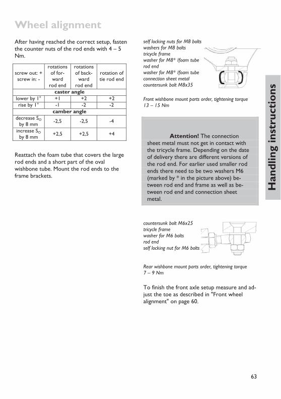
Wheel alignment
63
Han
dlin
g in
stru
ctio
ns
After having reached the correct setup, fasten the counter nuts of the rod ends with 4 – 5 Nm.
screw out: + screw in: -
rotations of for-ward
rod end
rotations of back-
ward rod end
rotation of tie rod end
caster angle lower by 1° +1 +2 +2 rise by 1° -1 -2 -2
camber angle decrease SO
by 8 mm -2,5 -2,5 -4
increase SO by 8 mm +2,5 +2,5 +4
Reattach the foam tube that covers the large rod ends and a short part of the oval wishbone tube. Mount the rod ends to the frame brackets.
self locking nuts for M8 bolts washers for M8 bolts tricycle frame washer for M8* /foam tube rod end washer for M8* /foam tube connection sheet metal countersunk bolt M8x35
Front wishbone mount parts order, tightening torque 13 – 15 Nm
Attention! The connection sheet metal must not get in contact with the tricycle frame. Depending on the date of delivery there are different versions of the rod end. For earlier used smaller rod ends there need to be two washers M6 (marked by * in the picture above) be-tween rod end and frame as well as be-tween rod end and connection sheet metal.
countersunk bolt M6x25 tricycle frame washer for M6 bolts rod end self locking nut for M6 bolts Rear wishbone mount parts order, tightening torque 7 – 9 Nm
To finish the front axle setup measure and ad-just the toe as described in "Front wheel alignment" on page 60.

64
Adjusting the suspensionSuspension and damping of Scorpion, Scorpion fx /fs 20 /fs 26 /Enduro /S-Pedelec, Scorpion plus 20 /plus 26
Rear suspension and full suspension tricycles allow compensation of bumps and roughness of the track for advanced comfort and reduce forces on the tricycle.
A well-adjusted suspension improves the trac-tion of your tricycle on uneven roads. Espe-cially when riding in a bend this allows a higher speed and also improves safety.
In order to achieve maximum riding comfort, the suspension settings have to match your weight as well as the road condition.
The goals of the adjustment are:
• maximum use of the available suspension travel without the suspension frequently bottoming out
• quick reaction of the suspension without obvious oscillation after having passed a bump
• avoiding self enforcing oscillations, that means increasing oscillations of the suspen-sion system due to pedalling influence, rhythmic body movements or permanent wavy underground
The improvement of road holding the suspen-sion gives you a plus of safety.
The suspension system of the rear swing arm consists of a spring and a damper.
Often, the terms suspension and damping are used inaccurate in everyday language.
The spring is the elastic element that com-presses and expands due to the load changes, which e.g. occur on bumpy roads. While ex-panding, the spring releases the same energy it took to compress it.
The rear swing arm is suspended with a steel coil spring in the standard version. The op-
tional rear shock ROCKSHOX Monarch uses air as spring medium.
The damper slows down the process of com-pression and expansion. That means the tricy-cle does not immediately "spring" back to the initial position or even further than that after having passed a bump. The damper converts spring energy into friction and finally into heat, and thus takes away energy from the suspen-sion system. The damper prevents the spring from swinging uncontrolled after an initial stimulation. In addition, the damper helps to avoid self enforcing oscillations of the suspen-sion caused by recurrent stimulation like ped-alling forces within a crank revolution or the rhythmic up and down movement of the legs.
In case you have mounted the optional sus-pension element ROCKSHOX Monarch, the hy-draulic damping of the rear suspension is adjustable. The more you increase the re-bound setting, the slower the system comes back to the normal position after a compres-sion.
Adjusting the suspension
You should always set the damping as low as possible to give the tricycle the possibility to quickly react even to several bumps in a row.
You can ride a recumbent tricycle with a con-siderably lower damping rate than for exam-ple a MTB: due to the relaxed and steady position of the body the recumbent does not experience extreme variations in the load as it is known from dancing on the pedals while riding uphill on a mountain bike.
In addition to this, varying pedalling forces have very little influence on the suspension of the tricycle due to the No Squat design of the suspension system of the tricycle. So when you adjust the damping, always start with a low damping rate.
It is necessary to choose the correct spring stiffness to have a well operating suspension

Adjusting the suspension
65
Han
dlin
g in
stru
ctio
ns
system. The spring stiffness is a measure for the compression of a spring at a certain load. It is either given in "N/mm" (Newton per Mil-limetres) or "lbs/inch" (Pounds per Inch). Sometimes you only find "lbs." printed on the springs. The spring stiffness of the optional air shock ROCKSHOX Monarch is set by adjusting the air pressure.
The suspension is designed in a way that the spring is compressed partly when you sit down on your tricycle. This is called negative suspension travel (or "sag") and it enables the spring to expand on bumpy roads. (This is in fact a definitely positive feature.) You should choose a spring stiffness with which this nega-tive suspension travel takes up around 30% of the overall suspension travel. This value usu-ally provides a very comfortable ride on your suspended recumbent tricycle.
Danger! While adjusting the rear suspension element never load the tricycle e.g. by resting on the seat or loading the rear rack when your hands or tools are close to the suspension element. Your hands may get caught and squeezed when the suspension compresses.
Adjusting to load
The luggage carrier of your recumbent tricy-cle is mounted to the suspended part of the frame. That way your luggage is also fully sus-pended and it spares the material. Most nota-bly, even under heavy load the suspension will compensate an uneven road much better and quicker compared to a design where the lug-gage carrier is mounted to the unsuspended parts, e.g. the rear swing arm.
Additional luggage changes the load on the wheels and their suspension. The springs are
further compressed initially through the load and there is less suspension travel for bumps while riding. Your suspension will bottom out more often.
The suspension of the front wheel is less af-fected since luggage at the rear rack almost only puts weight on the rear wheel. Only in case of heavy luggage on the lowrider under the seat there is an influence on the front wheel.
In order to compensate the variations in the load you can change the pre-load. For details see the following chapter.
Theoretically adjusting the preload can com-pensate for a load change of approx. 10 kg (23 lbs) at the rear wheel. In case of higher variations in the load you will have to ex-change the spring with a spring with different spring rate. In practice you can often do with-out it: With a suspension travel of 80 mm on the rear (and 60 mm on the front of full sus-pension tricycles there is a lot of suspension travel for a touring tricycle. When you choose the spring rate to have the full 80 mm at your disposal when your recumbent is under maximum load, you will have a somewhat smaller but still very comfortable suspension travel when you ride without luggage. The op-tional air shock ROCKSHOX Monarch can be easily pumped up to compensate load in-creases.

66
Rear suspension elementAdjusting the rear suspension element of all Scorpion models
Danger! While adjusting the rear suspension element never load the tricycle e.g. by resting on the seat or loading the rear rack when your hands or tools are close to the suspension element. Your hands may get caught and squeezed when the suspension compresses.
For the rear suspension a spring element is combined with a hydraulic damping unit in a suspension element. The damping results from fluid friction of oil flowing through thin holes of a valve in between two chambers inside the damper. A slightly noticeable sound that may occur from this oil flow is normal. Due to the fluid friction the spring element may heat up, therefore touch the spring element after a ride only very carefully.
Danger! The suspension ele-ments are filled with gas under high pres-sure. Never try to open the damper or to remove the screw at the gas tank. Inside the damper there are no user serviceable parts. In case of damage you will have to take the complete suspension element to your dealer.
The tricycle comes standard with a steel spring rear shock. As an option you can get the air shock ROCKSHOX Monarch that uses air as spring medium.
For a maximum of riding comfort the system should use about 30% of its travel while you sit on the tricycle in driving position. ("sag").
Steel spring rear shock DV-22
Adjustment
The preload determines how far the suspen-sion compresses when you are sitting on the tricycle while standing still.
Therefore it is necessary that you have the correct spring stiffness according to your weight. (On page 69 you will find more infor-mation about changing the springs).
Measure the distance between the two sus-pension element bolts or between rear rack and rear wheel while the tricycle is unloaded as well as while sitting on the tricycle in riding position. Also take into account possible lug-gage. Find out the total suspension travel pos-sible for your tricycle with the method described above, depending on the mounted add-on-parts and clips on the piston rod. The static compression should amount to about one third of the overall suspension travel.
You can affect this negative suspension travel depending on how much you weigh and how much you load your tricycle either by adjust-ing the suspension pre-load for fine tuning or by replacing the spring with a spring with a different stiffness in the rough tuning.
In order to adjust the suspension pre-load turn the adjustment ring on the threaded part of the suspension element by hand. Turning the adjustment ring clockwise (looking at it from behind) reduces the preload, turning it counter clockwise you screw the adjustment ring towards the spring and increase the sus-pension pre-load. It is helpful to turn the spring together with the adjustment ring.

Rear suspension element
67
Han
dlin
g in
stru
ctio
ns
Steel spring suspension element with fixed damping rate.
Danger! The adjustment ring has always to be screwed on so far that the spring has no play when unloaded. Other-wise the adjustment ring could come loose through shocks while riding and the slotted rear spring retention disc comes off. In that case the suspension element may be damaged or the rear wheel can hit the frame or rear rack, which may lead to se-rious falls. Always have an initial preload of at least half a turn on the spring.
The adjustment ring should be turned not more than five turns (measured from the re-laxed position) towards the spring. If the sus-pension compresses still too far even after six turns, the spring is too soft and has to be re-placed by a harder spring. A too high preload with a too soft spring will not take advantage of the full comfort potential.
Danger! Take care that the rear wheel or mudguard or suspension element never hit the frame, seat, rear rack or lug-gage box while the suspension is fully com-pressed. Therefore relax the spring completely by turning the spring retention disc on the thread of the spring element as far as pos-sible (before this, push the possibly existing safety spring ring from its slot in the threaded section as far as possible). Have a second person sit down on the tricycle and make the suspension bottom out by lean-ing on the seat or the rear rack. If the distance between the wheel or mud-guard and the frame, seat, or rear rack is smaller than 1 cm you will have to mount an additional spacer. In case you don't, the mudguard may break suddenly or the rear wheel might be blocked which can lead to serious crashes.
The suspension travel is adjusted by adding clips to the piston rod of the spring element.
Changing the steel spring (DV-22)
You can buy the spring for the rear suspen-sion element in different spring rates at your dealer.

Rear suspension element
68
We recommend the following spring rates, depending on the overall weight:
Load Spring stiffness
• up to 80 kg: 450 lbs/inch • up to 110 kg: 550 lbs/inch • up to 140 kg: 650 lbs/inch In addition to this, your dealer can also use springs with other spring rates or special lightweight springs made of titanium.
In most cases the rate is printed onto the spring. Pay attention to the correct imprint since the term "B650" that sometimes occurs does not necessarily mean 650 lbs/inch!
Spring length: DV22: 70 – 90 mm
In order to change the spring you will have to remove the rear screw and swivel away the rear frame.
Hold the main frame of your bicycle in a work stand.
If there is a safety ring at the thread of the suspension element move it to the end so you can unscrew the adjustment ring completely and then turn it to the outer position at the end. Remove the slotted spring retention disc at the other end.
Loosen the screws of the rear suspension element with two Allen keys and push the screw out of the suspension element’s eye.
Danger! If the bicycle does not stand on the ground while undoing the screws of the suspension element the rear swing arm may come down uncontrolled afterwards and hurt you seriously. In addi-tion to this the cables of the gear system and the brakes may overstretch and you will have to replace them. Ensure that the rear swing arm comes down in a con-trolled and gentle way by putting up a solid string or zip tie between the main frame and the rear swing arm.
Danger! When the bicycle is standing on the ground the frame and the swing arm come up against each other. Please make sure that this happens in a controlled and gentle fashion. Put a cloth between the contact surfaces. Otherwise, if they come up against each other uncon-trolled your hands may get caught between main frame, rear swing arm and suspension element and your bicycle may be damaged.
Move the rear swing arm down carefully. While doing this, take care that you don't bend or stretch any cables.
Remove the spring from the suspension ele-ment and put on the replacement spring. Make sure the new spring has the same di-ameter and length as the old spring and that it is supported safely by the adjustment ring.
Put back the slotted spring retention disc on the piston rod. If necessary, compress the spring a little bit. The spring retention disc has to match its support at the end of the suspen-sion element.
Secure the spring by tightening the adjustment ring until the spring doesn't show any more

Rear suspension element
69
Han
dlin
g in
stru
ctio
ns
play. If there is a safety spring ring, push it back into the slot on the thread.
Move the rear swing arm back up and connect the rear end of the suspension element with the rear swing arm using the bolt. Lubricate the bolt thoroughly.
Secure the screws of the suspension element with thread locker (e.g. LOCTITE 243) and tighten the screws with 6 – 8 Nm.
After having exchanged the spring you have to readjust the spring preload as described in the chapter on "Adjusting your new bicycle" on page 19.
Cleaning and lubricating
Do clean the suspension element, especially the polished piston rod, if it is dirty. Remain-ing dirt and sand can damage the seals of the hydraulic system and so shorten its life con-siderably. We recommend you to protect the suspension element from dirt with an elastic cover that you can buy at your local dealer when riding on dirty roads regularly.
From time to time grease the thread for the spring pre-load with a drop of acid-free oil. Thus, you can always turn the adjustment ring easily by hand. Once a year you have to grease the pivots of the suspension element. For that purpose dismount the suspension element as described under "Changing the spring" on page 69.
Remove the plastic spacers and pull the metal tube out off the bushing. Lubricate the bushing and the tubes with grease. Finally remount the suspension element.
Hydraulic dampers are affected by wear and tear through normal use. It depends on the usage of the tricycle, the amount of dirt on it and the maintenance and lubrication. After 3000 km the damper must receive an inspec-tion by a trained mechanic, worn out parts or the hydraulic cartridge can be replaced then. Due to wear of the seals oil can leak from the
damper. The internal oil can become foamy. This may lead to some noise when the damper is working. This noise does not affect the function of the damper. Only if there is no obvious damping after the first 5 mm of travel, the damper should be replaced.
Please also note the maintenance instructions of the damper manufacturer provided with your tricycle.
The bushings of the rear spring element need to be lu-bricated once a year.
Air shock ROCKSHOX Monarch
Attention! Please follow the in-structions in the separate manual provided by the rear shock manufacturer.
This rear shock contains pressurized air in a main („positive“) air chamber as suspension medium. Air shocks are lighter than steel spring rear shocks. Another advantage is that the spring stiffness can be easily adjusted with an air pump: By increasing the pressure the spring becomes harder.
Air shocks have progressive spring behaviour, whereas steel springs have linear spring be-haviour. This means that the air shock gets progressively harder, e.g. it is much stiffer when fully compressed than when only slightly compressed.

Rear suspension element
70
The advantage of this progressive spring be-haviour is the good bottom-out protection when heavily loaded.
The valve for the air chamber is located at the back end of the air shock. The valve is pro-tected by a metal valve cap.
To pump up the air shock you need a special air pump designed for bicycle air shocks. It must feature a fitting Schrader valve adaptor and a pressure indicator.
When attaching or removing the pump to/from the valve, you will lose some air pres-sure (about 0,5-1 bar). Take off the pump quickly.
Recommended pressure setting on Scor-pion fs 26 /Enduro / S-Pedelec, Scor-pion plus 26
Load pressure
• up to 80 kg (183 lbs) 7,5 bar • up to 110 kg (242 lbs) 9,0 bar • up to 140 kg (308 lbs) 10,5 bar
Recommended pressure setting on Scorpion, Scorpion fx, Scorpion fs 20, Scorpion plus 20
Load pressure
• up to 80 kg (183 lbs) 6,5 bar • up to 110 kg (242 lbs) 7,0 bar • up to 140 kg (308 lbs) 9,0 bar
Maximum allowed pressure: 18 bar.
Danger! Take care that the rear wheel or mudguard or suspension element never hit the frame, seat or rear rack box while the suspension is fully compressed. Therefore fully deflate the air shock. Have a second person sit down on the tricycle and make the suspension bottom out by pushing on the seat or the rear rack. If the distance between the wheel or mud-guard and the frame, seat or rear rack is smaller than 1 cm you will have to have your tricycle dealer mount an additional spacer inside the air shock. In case you don't, the mudguard may break suddenly or the rear wheel might be blocked which can lead to serious crashes.
Adjusting the damping
By adjusting the damping you can adjust the performance of the suspension precisely to your individual riding situation. A rough street with many harsh bumps that occur in a row or even cobblestones needs a low damping rate while a road with long stretched bumps that occur more regularly needs a stronger damping to achieve a smooth road holding.
When you add a lot of luggage you will need to adjust the spring stiffness; in that case an adjustment of the damping may even give you more riding comfort.
Finally, the oil used in the damper becomes thicker and more viscous at lower tempera-tures, which can be compensated through a change in the damper setting.
Please note that you can seriously spoil the riding comfort by a bad damper setting, espe-cially caused by unsystematic playing with the knobs that may result in much to high damp-ing values. In the worst case the suspension element will neither compress nor decom-

Rear suspension element
71
Han
dlin
g in
stru
ctio
ns
press. If you are in doubt please consult your local dealer.
The rebound damping prevents an eventual "jumping" of the rear wheel and provides a good traction. By improving the road surface contact the suspension of the recumbent tri-cycle also increases your riding safety.
Air Shock ROCKSHOX Monarch damping is adjusted with the red knob at the rear end. Watch correct mounting direction depending on your model! (Lever facing up-wards on Scorpions 26" models and downwards on Scorpion 20" models)
A higher damping value prolongs the time un-til the decompression movement is finished. Only then can the suspension compensate the next shock with the full suspension travel. Therefore, when you ride on very bumpy streets with shocks that occur fast in a row you might want to use a lower damping value.
A good setting for maximum comfort is achieved when the rear wheel decompresses completely after a shock and then oscillates only once. In order to check the adjustment you will need a second person that com-presses the suspension by pushing the tricycle down while you are sitting on the tricycle in the riding position. The other person can then observe the suspension movements.
In order to adjust the damping during decom-pression, turn the adjustment knob on top of the rear end of the suspension element.
If you turn the knob in direction of the „-“ you will get less damping and thus faster de-compression. Turning the knob in direction of the „+“ will give you more damping and thus slower decompression.
Attention! When mounting the Air shock to the frame, take care to place it in correct position: The lever must not get in contact with the frame or swing arm when the shock is being compressed. On Scorpion fs 26 tricycles, the blue lever must be on the rear facing upwards. On Scorpion, Scorpion fx and Scorpion fs 20 the blue lever must be on the rear fac-ing downwards.

72
Front suspension elementsAdjusting and maintenance on the front suspension of Scorpion fs 20, Scor-pion fs 26 /Enduro /S-Pedelec, Scor-pion plus 20 and Scorpion plus 26
Danger! While adjusting the front suspension, never load the tricycle, e.g. by resting on the seat or loading the racks when your hands or tools are close to the suspension struts. Your hands may be bruised when the suspension com-presses.
Full suspended tricycles of HP VELOTECHNIK are equipped with a suspended front axle. It is designed as a so called McPherson strut. That means, the left (or right) suspension strut's upper end is supported in the frame while it is linked to a single wishbone on its bottom end. The front wheel is directly attached to the suspension strut, which is the knuckle at the same time.
Inside the suspension strut a steel spring is combined with MCU-elastomers. The front suspension is damped by friction between stanchion tube and a circular elastomer band situated between the bushings as well as by friction inside the elastomers.
To decrease body roll in during fast cornering and to provide high comfort at the same time, the front axle is equipped with a stabilizer bar. This bar is linked elastically with both wishbones and the main frame. As the stabi-lizer bar works as a torsional spring, it sup-ports the outside wheel's suspension while cornering.
For maximum comfort, 30 % of the suspen-sion travel should be used when you sit on your tricycle in a normal driving position (the same is valid for the rear suspension). This means 20 mm of travel (so called "sag").
Your tricycle has reached a sag of 20 mm when the upper edge of the knuckle which you can feel underneath the shock boot coin-cides with the lower edge of the head tubes of the main frame. You can fine tune this sag according to your weight and your additional luggage by adjusting the preload of the springs. To change the spring rate in a wider range, you can replace the steel spring or inter-change elastomers and spacers inside the sus-pension struts. For further instructions, please see the chapter "Adjusting the suspension" on page 65. To adjust the preload of the front suspension, unscrew the strut end cap using a hex key size 5. Now the preload adjuster is visible, which can be turned by a hex key size 5, too.
Hex head screw for adjustment of the pre-load for the spring inside the knuckle
Turn the preload adjuster counter clockwise to decrease preload, turn it clockwise to in-crease preload. The maximum depth is lim-ited, so stop turning when resistance rises suddenly. After adjusting, place the cap on the strut and tighten it gently (1 – 2 Nm).

Front suspension elements
73
Han
dlin
g in
stru
ctio
ns
Danger! The mounted spring is under tension. Do not remove the preload adjuster when adjusting the spring preload. Make sure the adjusting disc's thread is fully screwed into the stanchion tube. Oth-erwise it may become loose and hurt you.
The damping rate can be altered by exchang-ing the elastomer bands inside the suspension struts, see “Removing and disassembling the suspension struts” on page 77.
Customizing the front suspension
The front suspension can be customized by different measures:
• - adjusting the preload (see page 22) • - exchanging the elastomers or spacers • - exchanging the steel springs • - exchanging the stabilizer bar • - exchanging the damping elastomer bands According to your order, the tricycle comes with standard suspension setup either up to 90 kg or above 90 kg.
Standard suspension setup up to 90 kg:
• - steel spring soft (red) • - 4 MCU elastomers 30 mm • - 1 spacer 30 mm • - stabilizer bar soft (white) • - low damping rate (elastomer bands
1,6 mm)
Standard suspension setup above 90 kg:
• - steel spring hard (yellow) • - 4 MCU elastomers 30 mm • - 1 spacer 30 mm • - stabilizer bar hard (grey) • - low damping rate (elastomer bands
1,6 mm)
Enclosed for individual setup:
• - 2 MCU elastomers 30 mm • - 2 spacers 30 mm • - 2 elastomer bands 1,7 mm, high damping
rate
These standard setups can be customized. As an example, you can find curves of different options in the diagram. The curve shape shows the characteristic of the suspension setup.
The characteristic is referred to as linear when the curve of suspension force related to suspension travel forms a straight line. Force and travel are related to each other by a con-stant factor, called spring rate, throughout the whole suspension travel. This is a typical char-acteristic of steel springs.
The characteristic is referred to as progres-sive (or rising rate) when the spring rate in-creases with suspension travel. In the diagram, this results in a curve with a left bend. Due to their design, elastomers and air springs show this characteristic (MCU elastomers show an almost linear characteristic in the first part of their travel, see curve nr. 4).

Front suspension elements
74
The tuning of your suspension bases on the choice of the steel spring according to your usual load. The soft spring moves the area of operation to low rider and luggage weight, the hard spring to high rider and luggage weight. The suspension characteristic is not affected by choosing another steel spring with different spring rate.
Varying the number of elastomers and their relation to the number of spacers inside the steel spring changes the area of operation as well as the suspension characteristic. It is al-lowed to have one or more blank spaces out of the five spaces available for elastomers or spacers. In this case the load during the first part of the travel is only taken by the steel spring and the elastomers only affect the sus-pension after the travel of the blank spaces is used up.
Attention! Do not install more than two spacers in one strut, otherwise the full suspension travel can not be reached. Spacers should always be installed at the top of the stack inside the spring to give room for the screw in the top cap. The setup must be similar in both suspen-sion struts of your tricycle.
Attention! The suspension must be set up in a way that avoids permanent bottoming out (a clearly recognizable bumping into the end stops). Permanent bottoming out may reduce the compo-nents' life time.
If you use your full suspension tricycle under different conditions and changing loads as well as on good and bad surfaces, a setup with a progressive characteristic for the whole travel is recommended to get a comfortable suspen-sion under all conditions of use. The elastom-ers support the steel spring from the beginning. By changing the relation between the number of elastomers and number of spacers, you can influence the suspension characteristic and the maximum force the strut can bear before it bottoms out.
Examples in the diagram are the curves nr. 1 and nr. 2 which show the standard setups. They feature moderate progression and in-creased maximum load compared to a single steel spring. (Setup: spacer-spacer-elastomer-elastomer-elastomer)
Will your tricycle always face the same load and only high quality roads, for example, you may tune your suspension characteristic to a more linear behaviour in the first two thirds of travel and a high progression in the remain-

Front suspension elements
75
Han
dlin
g in
stru
ctio
ns
ing third. The linear part provides very high comfort. The progression at the end prevents the strut from frequently bottoming out due to unusual high loads.
A characteristic like this (3) can be achieved by a steel spring which is responsible for tak-ing all the load at first and will be supported by only a few elastomers towards the end of travel. (Example setup: empty-spacer-spacer-elastomer-elastomer)
To exchange elastomers or spacers, the end cap and the preload adjuster (which is under tension) must be removed. Having done so, the steel spring and the inside elastomers and spacers can be taken out. The lower support of this suspension package is an axial bearing which consists of three parts. This bearing or its parts may stick to the spring (caused by lu-bricant). Make sure this axial bearing is mounted under the spring in the correct or-der (washer-bearing-washer) during reassem-bly. If there are elastomers left in the strut, a thin needle pricked into will help to remove them. Now the springs, elastomers, and spac-ers can be recombined. When screwing in the preload adjuster disc, make sure it is aligned straight. It must be screwed in against spring force, therefore the assistance of a second person might be asked.
Attention! Make sure that the axial bearing was mounted correctly be-tween spring and support plate inside the strut during assembly. A missing or wrongly placed axial bearing may damage the suspension strut or lead to steering heaviness.
Loosen the hex head bolt on the clamp before adjusting the-pre load
Stabilizer bar
To decrease body roll while cornering, the axle is equipped with a stabilizer bar. As long as the spring deflection height is the same on both front wheels, the stabilizer bar has no ef-fect. If one single wheel is moving upwards (e.g. the outside wheel due to the dynamic forces at high speed cornering), the stabilizer bar works as a torsional spring and increases the spring rate of this wheel. Besides, it transmits parts of this wheel's load to the op-posite wheel's suspension strut which then supports the higher-loaded wheel. As a result of this the single-sided suspension on bad quality roads will be harder compared to both wheels moving at the same time in the same direction.
If you prefer a very comfortable ride, it is pos-sible to mount the soft (white) stabilizer bar in spite of high loads and appropriate spring setup. However, the Scorpion fs 20 will lean more outwards in fast driven corners.
If you prefer a sporty style of riding with a minimum of body roll, you may also use the hard (grey) stabilizer bar with a soft spring setup.
To remove the stabilizer bar, simply unscrew both bolts which connect the stabilizer bar brackets to the frame plates. Now the stabi-lizer bar can be pulled out of its bushings in the wishbones. The aluminium brackets can

Front suspension elements
76
be removed afterwards. Assembly is done in reversed order.
Attention! Before inserting the countersunk bolts, make sure the brackets are fitted planar to the frame plates and the hole centres are aligned to each other. Otherwise you may damage the threads and destroy the brackets.
Removing and disassembling the suspension struts
To provide a long lasting, faultless function of the front suspension, the struts must be main-tained regularly according to the service plan on page 98. During design, great importance was attached to keep the bearings of the front suspension free from dirt and moisture. That's why the struts are equipped with a shock boot with vent holes situated inside the frame's steering tubes. This makes sure that predominantly clean and dry air is exchanged. Depending on the area and conditions the tri-cycle is operated in and under, dirt and mois-ture could nevertheless reach the bearings inside. Hence it is necessary, especially after riding under rainy and snowy or off road con-ditions, to check the struts for dirt and clean them. Under extreme conditions, we recom-mend to shorten the maintenance intervals given in the service plan.
Danger! While adjusting the front suspension, never load the tricycle, e.g. by resting on the seat or loading the racks when your hands or tools are close to the suspension struts. Your hands may be bruised when the suspension com-presses.
Attention! Use aging-resistant, lithium soap based grease to lubricate. Never use grease containing solid lubri-cants such as molybdenum disulfide or zinc sulphide.
Attention! Never clean your tricycle and especially parts of the suspen-sion with a pressure washer or steam cleaner. These devices remove lubricant and transport dirt into the bearings which causes higher wear.
Attention! Always secure the wishbones or track rods by tying them to the frame (e.g. using zip ties) to make sure they won't move until their stop. This would damage the spherical plain bearings and rod ends.
To clean the suspension strut occasionally, clean the shock boot and slide it down com-pletely. Clean the stanchion tube thoroughly with a soft, dry cloth. Apply a thin layer of grease or suitable oil. Finally, slide back the shock boot to its original position.
To maintain the suspension strut according to the service plan or to exchange the elastomer bands for damping adjustment, it has to be removed and disassembled. Therefore, fit the tricycle to a work stand in a way that provides easy access to the respective front wheel. Remove the front wheel. Remove the brake caliper according to the manufacturer's man-ual. Unfasten the fender (see page 82). De-mount the stabilizer bar as described above.

Front suspension elements
77
Han
dlin
g in
stru
ctio
ns
Unscrew the outer rod end of the track rod from the suspension strut. The lower collar of the rubber cap must be slid upwards to access the self-locking M6 nut.
Unscrew the hex bolt M6x40 A at the strut's lower end, which connects the strut with the wishbone.
Now remove the end cap B at the suspension strut's upper end. Unscrew and remove the clamp C as well as the spacer D, F, cap E and spacer F below. Pivot the strut in a way that it may pass the wishbone and push it down-wards to slide it out of the elastomer bearing G. In case the strut won't pass the wishbone, you have to dismount the wishbone's rear pivot point.
Exploded view of the suspension strut assembly
Slide off the washer H at the suspension strut's upper end. For further disassembly, cut the zip tie at the bottom of the shock boot 1 and slide the shock boot off the strut. Now screw in hex bolt A, on the underside of the strut for approximately 4 mm. Grab the sus-
pension strut firmly at the knuckle (lower black part) and beat the screw head with a rubber hammer to release the piston 6 inside.
Attention! We recommend us-ing CONCEPT-Lube available from HP VELOTECHNIK for best performance. You can also use aging-resistant, lithium soap based grease to lubricate. Never use grease containing solid lubricants such as molybdenum disulfide or zinc sulphide.
A hammer punch on the bolt releases the piston inside the knuckle.
Remove the hex bolt A and slide the stan-chion tube 3 (golden) out of the knuckle.
The elastomer band 8 can now be removed. Clean the sliding surfaces of the stanchion tube and the bushings 4, as well as the inside of the knuckle 2. Use a clean soft cloth. If there is noticeable play in the bushings or if the bushings are damaged, please contact your dealer. Lubricate the surfaces of the clean bushings 4. Check the proper position of the bottom out elastomer 5 inside the knuckle. Apply a thin layer of grease on the stanchion tube 3.

Front suspension elements
78
Applying grease to the bushings.
Insert the elastomer band without wrinkles in the knuckle between the two bushings. Slide the stanchion tube back into the knuckle. Slide on the shock boot and insert its upper end into the stanchion tube's groove. Apply a new zip tie to its lower end. Slide on the washer H. Press the suspension strut into the elas-tomer bearing in the frame. Assemble spacer F, cap E, spacer D, clamp C, and end cap B. Fix the suspension strut in its elastomer bear-ing by tightening the end cap with 1 – 2 Nm and fasten the clamp.
Connect the suspension strut with the spheri-cal plain bearing in the wishbone by the M6x40 hex bolt (part order: strut – thin seal-ing ring I – pivoting bearing J – spacer 6 mm long K with thick sealing ring L – screw head A). Tighten the screw with a torque of 9 – 10 Nm. By doing this, the piston is locked at the lower end of the suspension strut in its correct position.
Exploded view of the suspension strut interior
Attention! Use thread locker (e.g. LOCTITE 243) with all bolted connec-tions that are not equipped with self-locking nuts, else the connections may be-come loose.
When mounting the rod end at the suspen-sion strut, take care to assemble the parts in the correct order, from upside: screw head, steering lever, washer 6, spacer 6 mm length, rod end, self-locking nut M6. In case you have removed the rubber cap, circlip pliers will help you to reassemble.

79
Han
dlin
g in
stru
ctio
ns
Swing arm pivotSwing arm pivot on Scorpion models
The rear swing arm pivot comes with mainte-nance free bushings. They feature a self lubri-cating system with Teflon particles. The bushings sustain a very high load and they show almost no wear.
In case you notice play or a creaking noise at the rear swing arm please check the two screws that keep the axle in the frame. They have to be secured with thread locker.
Tightening torque: 17 – 19 Nm (Please follow the tightening torque settings listed in the table on page 88.)
Danger! If the screws at the axle are not tight enough this leads to play and noises when the spring compresses. In ex-treme cases the swing arm may come loose which leads to a serious fall. If the screws are too tight the thread of the axle may tear out or the screw may be dam-aged.
The bushings are exchangeable. For that pur-pose you will have to dismount the rear swing arm and send it together with the axle via your specialist dealer to HP VELOTECHNIK. Af-ter installation the bushings are machined to adjust them.
Unscrewing the axle bolts
Before being able to unscrew the axle bolts a possible rear rack must be disassembled. To do so both lower screws of the rear rack must be unscrewed completely, both upper screws must be loosened. Then, the rear rack can be swivelled upwards.
In case the rear swing arm is to be dis-mounted completely you can prevent the axle from turning by inserting a thin metal rod in
the hole of the axle through the hole in the rear swing arm under the axle.
Attention! There has to be a big washer between the main frame and the end of the bushing else the bushing is not able to function without play and the frame will be damaged.
You can prevent the axle from turning by inserting a thin metal rod in the hole of the axle. Upper picture: Scorpion fs 26 and Scorpion plus frames Lower picture: Scorpion fx

80
MudguardsMudguards are exposed to very strong vibra-tions, especially at suspended wheels, which may cause them to break. Please check the stays and mountings of the mudguards regu-larly for their position and check the mud-guards themselves for cracks or deformations. Replace damaged mudguards immediately.
Front mudguards
If the wheels are removed, the tricycle must not rest on the front mudguards. Loosen the screw between mudguard mounting and knuckle to remove the mudguard.
The front mudguards are adjustable in height to accommodate different tire heights by means of the slotted holes in the mudguard mounting.
After having performed service work or after replacing mudguards check if the wheels turn freely. There has to be a distance of at least 7 mm between mudguard and wheel.
Check whether the suspension can still be completely compressed with mounted mud-guards. The mudguards, stays, mountings, and screws must not touch other parts under maximum compression.
Danger! If branches or other obstacles get caught in the wheels while riding and are moved around they may drag the mudguards along. The mudguard can possibly fold up between frame and tire and hence block the wheel, which may lead to a serious fall. If you hear any un-known noises while riding stop immedi-ately and remove anything that might cling to the mudguards or the wheels.
Attention! You must not mount additional parts like rear lights or reflec-tors to the mudguards since those may break then. Retrofit mudguards are aligned at HP VELOTECHNIK before they are sent out. After assembling them to the tricycle a final alignment must be performed.
Mounting of front mudguard on Scorpion fs 20, Scorpion fs 26 /S-Peldelec, Scorpion plus 20 / plus 26
The front mudguard mounting is attached to a bracket on the suspension struts.
The sheet metal mounting bolts (facing the wheel) must be fastened with 7 – 9 Nm.
To remove the mudguards unscrew the sheet metal mounting bolts until the sheet metal can be pulled out. Secure or remove the sheet metal mounting bolts.
Retrofit mudguards are aligned at HP VELOTECHNIK before they are sent out. Af-ter assembling them to the tricycle a final alignment must be performed.
Danger! Make sure that the sheet metals are fastened with the correct tightening torque (7 – 9 Nm) and the screws are secured with retaining washers and thread locker. Frequently check the assembly. If a sheet metal becomes loose, the fender may be caught by the wheels and lock the wheel or flung away. This may lead to serious injury or fall!
.

Mudguards
81
Han
dlin
g in
stru
ctio
ns
Mounting of front mudguards on Scor-pion, Scorpion fx, Gekko fx 20 and Gekko fx 26
The front mudguard mounting is attached by headset’s cap and screw and fastened against the headset clamp. Make sure this clamp is fastened properly
The little screw in the mudguard mounting fits in the clamping slot of the headset clamp and secures the mounting against turning.
If you decide to uninstall the mudguards, re-place the mudguard mounting with a 5 mm spacer.
Mounting of front mudguards on Scorpion, Scorpion fx, Gekko fx 20 and Gekko fx 26

82
Water bottle cagesWater bottle cage
The derailleur tube at the front of the frame comes with threaded inserts M5 for an addi-tional water bottle cage as well.
A useful alternative to water bottles are sys-tems with a "water bag" and a drinking hose, e.g. from CAMELBAK. You can simply strap them behind the seat or on the rear rack.
Water bottle cages for ErgoMesh- and Gekko-seats
You can mount a water bottle cage with a special bracket behind the seat. Therefore, water bottle kits are available as special acces-sories from HP VELOTECHNIK.
There are threads in the back of ErgoMesh and Gekko seat frames to mount the water bottle brackets in an upper or lower position.
Gekko fx 20 with water bottle cages mounted in the lower position
Water bottle cages for BodyLink-Sitz
For the BodyLink-seat there is a special mounting sheet for the water bottle brackets available at HP VELOTECHNIK, witch allows mounting of water bottle brackets in the up-per or lower position of the seat!

83
Mai
nten
ance
and
car
e
Maintenance routine Your tricycle is equipped with the latest bicy-cle technology that does not require much maintenance.
However, you will have to maintain your bicy-cle regularly, as it is with other vehicles too. At least once a year the bicycle has to be taken to a bicycle mechanic for an overall ser-vice. Only this way a long lasting and safe function of all parts of your bicycle can be guaranteed. It maintains the value of your bi-cycle as well as the fun and the safety while riding for many years.
Read in this chapter how to perform smaller maintenance and care works between the services.
For a quick overview of the works to be done take a look at the Warranty Pass on page 91.
Attention! The maintenance works on this recumbent partly require special tools and skills. Do only work within your limits and, in the interests of your own safety, do not go beyond. Should you be uncertain at any point, get in con-tact with your local dealer.
Wear and tear
As on many other vehicles, some parts on a bicycle are affected by wear and tear. The life-time expectation of these parts depends on the intensity and type of use as well as on the maintenance and care. Please keep in mind that the process of wear and tear is normal and no reason for a warranty claim against your dealer or HP VELOTECHNIK.
You will find more specific information on wear and tear in the chapters on the relevant parts.
Cleaning and conservation
The frame of your recumbent tricycle has a high quality and environmentally friendly pow-der coating. The surfaces of the aluminium parts are either polished or anodised. Threads and technical contact areas can be unfinished and must be protected with wax.
To keep the surfaces brilliant over many years and to protect them effectively against corro-sion the bicycle has to be cleaned from dirt and then conserved.
Dried sweat but also environmental influences such as air pollution, dirt on the roads and es-pecially grit affects the parts, and not only may this cause flaws but also serious structural damage of the parts by corrosion.
In contrast to a widespread belief particularly the "non-rusting" aluminium is dramatically af-fected by grit! This kind of damage may not be visible in the beginning but it leads to a serious danger when the part breaks. Clean and con-serve your bicycle diligently!
The best things to clean your bicycle with are warm water and a soft cloth. If your bicycle is very dirty first take a wet sponge to soften the dirt and then remove it. In case of bad grease or oil stains you should use a special cleansing agent for bicycles in addition.
While cleaning your bicycle check it for any cracks, scratches, deformations, damaged parts, loose spokes etc. If you are in doubt please consult your local bike shop.
Maintenance and care

Maintenance routine
84
Attention! Do not use any cleansing agents that scrub or are chemi-cally aggressive since they affect the paint-work. Before using any cleansing agent please test it at a part of your bicycle that is not immediately visible.
Attention! Do not use any high-pressure cleaner. The strong jet of water goes through the seals of the bearings, blows away the lube and causes corrosion of the bearing parts and the chain. In addi-tion to this it may damage stickers.
Attention! Any damage of the paintwork has to be cleaned from rust and repaired immediately, else the damaged part in the frame gives way to corrosion that nests in the surrounding paintwork. This can result in damage of the frame.
In case of small scratches at the surface of the powder coating of the frame or the surface of the seat you can simply polish them away. You can buy a special polishing agent for epoxy resins at a specialist dealer for boat building. Do not use a polish for metal!
After cleaning the tricycle, dry it and treat the paintwork and the metal surfaces with wax. You can purchase this wax from your local bike dealer as a convenient spray.
The wax passes moisture and flows into tiny gaps and pores. After some minutes the sol-vent evaporates and leaves a dull and gluti-nous film. Now polish the waxed parts of
your bicycle with a soft cloth to make it real shiny.
Do not only wax the frame but also the spokes, hubs, screws and nuts etc. You can also conserve the chain with wax spray after lubricating it, see also the chapter on "Chain", page 51.
The frame has small holes for ventilation that prevent condensation in the frame. These holes must not be sealed. However, moisture may enter the frame through the holes. Therefore protect the inside of your frame by applying wax spray through the holes.
Protect the parts where cables or chain tubes may scratch the frame. You can buy special stickers at your bike dealer or extra strong transparent tape at your do-it-yourself-store. That way you avoid scratches in the powder coating and coating coming off.
Attention! Take care that after folding the tricycle there are no parts rub-bing against the frame. This may damage the paintwork.
Maintenance routine
85
Mai
nten
ance
and
car
e
Storing the bicycle
Before storing your bicycle over a longer pe-riod of time, e.g. during winter, please take care of the following steps:
• Clean your bicycle and protect it from cor-rosion as described in the chapter on "Cleaning".
• Store your bicycle in a dry and warm place. Avoid direct sun and storage close to the heating since it affects the rubber of your tires.
• Choose the smallest sprocket and the smallest chain ring. That way the cables are in the most relaxed position.
• The tubes of your tires loose air when standing over a longer period of time. If the bicycle then rests on flat tires the tires may be damaged. Therefore hang up your bicycle or check the air pressure regularly.
The winter months are a convenient period of time for the annual service since then you won't have to wait long for an appointment. Many dealers offer special prices for the win-ter check.
Transport in the car
The best way to transport your tricycle is in-side the car. Take care that it does not lie on the derailleur.
If you want to transport it outside the car we recommend a roof-rack or a rear carrier. Take care to fasten your tricycle at the frame only.
Please remove any parts that could come loose during transport (seat cushion, water bottles, luggage bags, pumps, pennants, etc.).

86
Tightening torques Table of tightening torques for all Scorpion models
The values indicated are meant for a friction value =0,125 (greased threads and screw heads). They only refer to the indicated parts. Please do always follow the values given in the manuals of the parts manufacturers since the following values may not be up to date due to changes in the product line! part connection screw tightening torque V-brake - brake lever handlebar/grip M6 SW5 4 Nm- brake caliper - caliper/frame M6 SW5 5 – 7 Nm - cable clamping M6 SW5 6 – 8 Nmdisc brake - brake lever handlebar/brake lever clamping M6 SW5 4 Nm- brake caliper caliper/frame M6 SW5 7 – 9 Nm- brake disc disc/hub M5 Torx T25 5 – 6 Nm- brake tube brake tube/brake lever SW8 4 Nmdynamo dynohub/mounting sheet M6 SW5 6 – 8 Nm mounting sheet/frame M5 SW4 4 – 6 Nmfolding hinge locking wedge screw M6 SW4 6 Nmsuspension element frame/susp. element/swing arm M6 SW4 6 – 8 Nmrear rack at the seat tube M6 SW5 7 – 9 Nmswing arm axle/frame M12x1 SW6 17 – 19 Nmbottom bracket cartridge/frame 50 – 60 Nmchain idler chain idler/frame M8 SW6 17 – 19 Nmcrank crank/axle SW8 35 Nm chain ring screws SW5 8 – 11 Nmhub cassette ring 38 – 42 Nm front hub quick mount M8 SW5/SW6 8 – 10 Nmquick release lever 9 – 12 Nmpedal pedal/crank SW15 35 – 40 Nmshifting lever twist shifter SW3 2 – 2,5 Nm barend shifter SW6 5 – 6 Nmderailleur derailleur/frame SW5 8 – 10 Nm cable clamping SW5 4 – 6 Nmmud guard stays/frame M5 SW4 4 – 5 Nmseat upper seat/seat mount M6 SW4 5 – 6 Nm lower seat/seat mount M6 SW4 3 – 4 Nmframe front boom clamping M8 SW6 14 – 16 Nmfront derailleur front derailleur/frame M5 SW5 5 – 6 Nm cable clamping M5 SW5 4 – 6 Nmhandlebar handlebar/stem M6 SW5 8 – 10 Nmstem main axle/bearing SW6 6 – 8 Nmfront axle A-Head-cap M6 SW5 1 – 2 Nm clamp on stanchion tube M6 SW5 7 – 9 Nm steering rod/knuckles M6 SW5 7 – 9 Nm wishbone/strut M6 SW 10 9 – 10 Nm wishbone/main frame M8 SW5 13 – 15 Nm wishbone/main frame M6 SW4 7 – 9 Nm

Tightening torques
87
Mai
nten
ance
and
car
e
Tightening torques for Gekko fx 20 and Gekko fx 26
The values indicated are meant for a friction value =0,125 (greased threads and screw heads). They only refer to the indicated parts. Please do always follow the values given in the manuals of the parts manufacturers since the following values may not be up to date due to changes in the product line! part connection screw tightening torqueV-brake - brake lever handlebar/grip M6 SW5 4 Nm- brake caliper - caliper/frame M6 SW5 5 – 7 Nm - cable clamping M6 SW5 6 – 8 Nmdisc brake - brake lever handlebar/brake lever clamping M6 SW5 4 Nm- brake caliper caliper/frame M6 SW5 7 – 9 Nm- brake disc disc/hub M5 Torx T25 5 – 6 Nm- brake tube brake tube/brake lever SW8 4 Nmdynamo dynohub/mounting sheet M6 SW5 6 – 8 Nm mounting sheet/frame M5 SW4 4 – 6 Nmrear rack at the seat tube M5 SW4 5 – 6 Nmbottom bracket cartridge/frame 50 – 60 Nmchain idler chain idler/frame M8 SW6 17 – 19 Nmcrank crank/axle SW8 35 Nm chain ring screws SW5 8 – 11 Nmhub cassette ring 38 – 42 Nm front hub quickmount M8 SW5/SW6 8 – 10 Nmquick release lever 9 – 12 Nmpedal pedal/crank SW15 35 – 40 Nmshifting lever twist shifter SW3 2 – 2,5 Nm barend shifter SW6 5 – 6 Nmderailleur derailleur/frame SW5 8 – 10 Nm cable clamping SW5 4 – 6 Nmfront derailleur front derailleur/frame M5 SW5 5 – 6 Nm cable clamping M5 SW5 4 – 6 Nmframe front boom clamping M8 SW6 14 – 16 Nm frame clamping M8 SW6 14 – 16 Nmmud guard stays/frame M5 SW4 4 – 5 Nmhandlebar handlebar/stem M5 SW4 4 – 6 Nmstem stem/axle M5 SW4 4 – 6 Nmheadset headset clamp M6 SW5 4 – 6 Nmtrack rods track rod/knuckles M6 SW5 7 – 9 Nm counter nut SW10 4 – 5 Nm

88
WarrantyWarranty policy
Your authorised dealer has to fully set up and adjust your bicycle, so that safe function is guaranteed. The dealer has to make a final safety check and carry out a test ride.
Your cycle dealer is obliged by law to ensure, among other things, that your bicycle is not affected by defects which materially diminish its value of suitability for the described pur-pose. The exact details will vary according to the country. In Germany, this liability ends two years after purchase.
In addition to this HP VELOTECHNIK offers a 10 year warranty on the frame against damage through material or manufacturing defects. This warranty applies only to the original pur-chaser.
Damage caused by wear and tear, corrosion or damage at the surface coating is excluded.
Damage caused by inappropriate use, inade-quate care and maintenance, falls, crashes, overloading through excess weight, incorrect assembly or modifications to the tricycle is also not covered. The onus rests with the purchaser. The warranty is void if any of the instructions in this manual are neglected.
Warranty is only valid for original parts from HP VELOTECHNIK. In case of warranty we will replace or repair the damaged part with a part of our choice or a new part equal to the old one (warranty obligation). We do not cover any transport, labour or any secondary costs.
The warranty is void when using the bicycle for commercial purpose such as rental or leasing
The warranty starts with the date of purchase (receipt of the tricycle dealer) of a new bicy-cle. The warranty is processed via the tricycle dealer who ordered the bicycle from us.
In case of damage the dealer has to send the damaged frame to us so that we can check it, if asked to do so by us.
In the event of any action that falls under war-ranty the original warranty period will not be prolonged and no new warranty will be given. If HP VELOTECHNIK refuses to count a repair as warranty case we will only carry out a re-pair with costs after having talked to the cus-tomer or his representative, the respective dealer.
It is necessary for the purchaser to fill in the enclosed warranty registration form to benefit from the extended warranty. This filled in form has to be sent to HP VELOTECHNIK within 4 weeks after the purchase.
The warranty is only valid when the warranty pass at the end of this manual has been filled in when you received your tricycle and when every inspection listed has been done and re-corded by your bicycle mechanic within the described time schedule.
In the event of any warranty the warranty pass together with a copy of the proof of pur-chase has to be sent to HP VELOTECHNIK through your dealer.
This warranty does not have any influence on the rights of the purchaser according to his statutory rights.

Warranty pass
89
War
rant
y
Warranty pass
With the HP VELOTECHNIK Warranty Pass you can assure the safety and proper function of your tricycle for many years.
Like any other vehicle your tricycle has to be checked for safe operation before riding. Your bicycle has to be maintained at regular inter-vals, at least once a year you will have to take your tricycle to a qualified bicycle mechanic for a thorough check.
The service plan on the next page shows you our mandatory maintenance and service works.
If you wish you can set an upper price limit for the service with your bicycle mechanic. If the necessary works exceed this limit you will be informed in advance.
You can avoid seasonal waiting periods in spring and summer when you have your an-nual inspection done in the quiet months from October to January. Many bike shops then have special winter check offers. At any rate do make an appointment. Clean your bicycle prior to the inspection since then many of the checks by sight can be done quickly and at low cost.
Please have your specialist dealer record every inspection and service work in the Warranty Pass. This is a requirement for the validity of our extended warranty that ex-ceeds the legal warranty.
name:
address:
telephone:
frame no. (see page 9 and following for fur-ther information):
I have received the bicycle in good condition, adjusted to my size and performed a test ride. I have been informed about the correct use of the recumbent, the components like derailleur and especially steering and brakes as well as the necessity of regular service and mainte-nance. I will read the manuals prior to the first ride and have all future users read them too. I am aware that I need to send the warranty registration form to HP VELOTECHNIK within four weeks of the purchase to qualify for the extended warranty.
Date:
customer's signature:
dealers signature and stamp:

Warranty pass
90
Service at delivery
At the delivery of a new tricycle:
Order No.:
mileage approx. km:
Date:
Dealer's Stamp and Signature:
Exchanged or additionally mounted parts:
(When you assemble a frame kit please list the components on an extra sheet and attach it to this Warranty Pass.)
1st service
No later than 300 kilometres or 2 months af-ter the purchase.
Order No.:
mileage approx. km:
Date:
Dealer's Stamp and Signature:
Exchanged or additionally mounted parts:

Warranty pass
91
War
rant
y
2nd service
No later than 3000 kilometres or one year af-ter the purchase.
Order No.:
mileage approx. km:
Date:
Dealer's Stamp and Signature:
Exchanged or additionally mounted parts:
3rd service
No later than 6000 kilometres or two years after the purchase.
Order No.:
mileage approx. km:
Date:
Dealer's Stamp and Signature:
Exchanged or additionally mounted parts:

Warranty pass
92
4th service
No later than 9000 kilometres or three years after the purchase.
Order No.:
mileage approx. km:
Date:
Dealer's Stamp and Signature:
Exchanged or additionally mounted parts:
5th service
No later than 12000 kilometres or four years after the purchase.
Order No.:
mileage approx. km:
Date:
Dealer's Stamp and Signature:
Exchanged or additionally mounted parts:

Warranty pass
93
War
rant
y
6th service
No later than 15000 kilometres or five years after the purchase.
Order No.:
mileage approx. km:
Date:
Dealer's Stamp and Signature:
Exchanged or additionally mounted parts:
7th service
No later than 18000 kilometres or six years after the purchase.
Order No.:
mileage approx. km:
Date:
Dealer's Stamp and Signature:
Exchanged or additionally mounted parts:

Warranty pass
94
8th service
No later than 21000 kilometres or seven years after the purchase.
Order No.:
mileage approx. km:
Date:
Dealer's Stamp and Signature:
Exchanged or additionally mounted parts:
9th service
No later than 24000 kilometres or eight years after the purchase.
Order No.:
mileage approx. km:
Date:
Dealer's Stamp and Signature:
Exchanged or additionally mounted parts:

Warranty pass
95
War
rant
y
10th service
No later than 27000 kilometres or nine years after the purchase.
Order No.:
mileage approx. km:
Date:
Dealer's Stamp and Signature:
Exchanged or additionally mounted parts:
11th service
No later than 30000 kilometres or ten years after the purchase.
Order No.:
mileage approx. km:
Date:
Dealer's Stamp and Signature:
Exchanged or additionally mounted parts:

Warranty pass
96
12th service
No later than 33000 kilometres or eleven years after the purchase.
Order No.:
mileage approx. km:
Date:
Dealer's Stamp and Signature:
Exchanged or additionally mounted parts:
13th service
No later than 36000 kilometres or twelve years after the purchase.
Order No.:
mileage approx. km:
Date:
Dealer's Stamp and Signature:
Exchanged or additionally mounted parts:

97
Serv
ice
plan
Service plan The service plan on the next pages is intended to give you a rough overview over the re-quired maintenance and service works. In no case it can replace the detailed instructions in this manual!
You can perform service works marked with a “ “ if you have the required skills and tools as for example a torque wrench.
If you discover any defects while checking your bicycle they have to be repaired immedi-ately. If you are in doubt please consult your local bike shop.
Works marked with a “ ” should only be car-ried out by a trained bicycle mechanic.
At the annual service the bicycle mechanic has to carry out all works listed as well as all ser-vices and maintenance works necessary ac-cording to the momentary technical standard and professional knowledge.
Please follow at any rate the manuals of the parts manufacturers.
The service intervals given in this Warranty Pass refer to an average use and a riding per-formance of 3.000 km per year.
When you ride more kilometres per year or often ride under bad conditions like rain, grit or dirt it is necessary to have shorter mainte-nance intervals.
In order to measure your riding performance we recommend to use a bicycle computer.
The regular service maintains the safe opera-tion and the value of your bicycle. Not only does the completed Warranty Pass record the maintenance works for the validation of your warranty but also does it prove the care and the value of your bicycle – a good thing to have when you are going to sell your tricycle one day.

Service plan
98
Service plan part work lighting system check function adjust headlamp and rear light, check cable contacts clean reflectors, replace missing reflectors tires check air pressure check tread and sidewalls brakes check for damages check for leaking oil check rigid feel brake lever blades when pads reach rotor check brake pads for wear suspension element clean and oil thread, push rod, air chamber lubricate bushes replace worn out parts / hydraulic cartridge suspension struts front check shock boot and clean stanchion tube (not for Scorpion, Scor- disassemble, lubricate Gekko fx 20 and check for play Gekko fx 26) replace worn out parts rear swing arm check function and bearing play, tighten axle screws bottom bracket bearings check bearing play rims check wall thickness, wear, condition chain grease and check for wear chain tubes check for wear expand ends or exchange tubes chain roller check for wear, check bearing crank check, tighten paintwork conserve and repair wheels check alignment and spoke tension handlebar check for damage / bends check track rod for proper mounting headset no headset used on full suspension models (service suspension strut bearings in-hubs check bearing play and brake discs mounting pedal check bearing play, check binding mechanism frame check clamping of the front boom clean and conserve check for damage, damage to paintwork quick release check correct closing derailleur check for movement and function clean and lubricate screws and nuts check and tighten mudguards check for damage and correct position valves check for correct position and air tightness stem check clamping check clamping screws cables dismount, lubricate, replace if necessary

Service plan
99
Serv
ice
plan
see page before every ridemonthly annually Note
42
56
45
67
73 every 6 months
81
51 52
54
56
59/73 8 7 82 recommended interval to replace aluminium stem: 2 years
47/50

HP Velotechnik OHG ● German recumbent technology ● Kapellenstraße 49 ● D - 65830 Kriftelphone ++49 6192 - 9799 2 - 0 ● fax ++49 6192 - 9799 2 - 299 ● [email protected] ● www.hpvelotechnik.com
2016 recumbenttechnology
HPwww.hpvelotechnik.com
Velotechnik