2016 internship report
TRANSCRIPT
MAKERERE UNIVERSITY
COLLEGE OF ENGINEERING, DESIGN ART &
TECHNOLOGY
DEPARTMENT OF CIVIL ENGINEERING
SCHOOL OF ENGINEERING
THIRD YEAR INDUSTRIAL TRAINING REPORT
(6TH JUNE TO 29TH JULY 2016)
NAME: KAGANZI KENBERT
REG NUMBER: 13/U/298
STD NUMBER: 213000715
DEPT SUPERVISOR: FIELD SUPERVISOR:
NAME: DR. TUMWESIGYE EMMANUEL NAME: DR. MWESIGE GODFREY
SIGNATURE……………………. SIGNATURE:………………………..
i
DECLARATION I KAGANZI KENBERT declare that this report is personally prepared and compiled by me, and
that the contents contained within this report have not been duplicated or published anywhere or
submitted to any university for any degree program by a student or any other person, unless
indicated. I have personally compiled it based on the experience and training I had under UB
consulting engineers Ltd, on the Seguku-Kasenge-Buddo road rebuilding project.
NAME: KAGANZI KENBERT
REG NO: 13/U/298
STUDENT NO: 213000715
SIGN ……………………………………….
DATE ………………………………………

ii
ACKNOWLEDGEMENTS I would like to thank the management and staff of UB Consulting Engineers Limited for the
opportunity they offered me to do undertake training with them
I would like to thank the management and staff of Abubaker Technical Services and General
Supplies Limited for the opportunity they offered me to do undertake training with them, on top
of which they tolerated my mistakes and too many questions as well as the facilitation offered in
term of meals.
I would like to thank my internship supervisor Dr. Tumwesigye Emmanuel for taking on the
responsibility to supervise me during my internship training
I would like to thank my parents for their unconditional willingness to meet all of my needs and
requirements as per the industrial training period, in terms of funding, advice and personal
guidance.
Finally, I would like to thank the Almighty God for the knowledge, wisdom, good health, safety
and ability he granted because without these, the success of this industrial training would not have
been possible.
iii
Table of Contents DECLARATION ............................................................................................................................. i
ACKNOWLEDGEMENTS ............................................................................................................ ii
LIST OF FIGURES ....................................................................................................................... vi
LIST OF TABLES ........................................................................................................................ vii
ABBREVIATIONS ..................................................................................................................... viii
ABSTRACT ................................................................................................................................... ix
CHAPTER ONE: INTRODUCTION ............................................................................................. 1
1.1 Background ........................................................................................................................... 1
1.2 Objectives ............................................................................................................................. 1
1.3 Project Setting ....................................................................................................................... 2
1.3.1 Consultant’s Background ............................................................................................... 3
1.3.2 Contractor’s Background ............................................................................................... 4
1.4 Road design specifications .................................................................................................... 5
1.5 Scope of works ...................................................................................................................... 5
CHAPTER TWO: LITERATURE REVIEW ................................................................................. 7
2.1 Pavement ............................................................................................................................... 7
2.1.1 Flexible Pavement .......................................................................................................... 8
2.1.2 Perpetual Pavement ........................................................................................................ 9
2.1.3 Rigid Pavement ............................................................................................................ 10
2.1.5 Rigid and Flexible Pavement Characteristics .............................................................. 11
2.2 Pavement Materials:............................................................................................................ 12
2.2.1 Soil ............................................................................................................................... 12
2.2.2 Aggregates: .................................................................................................................. 13
2.3 Earthworks .......................................................................................................................... 14
2.3.1 Site Investigation ......................................................................................................... 14
2.3.2 Clearing and grubbing.................................................................................................. 14
2.3.3 Excavation.................................................................................................................... 15
2.3.4 Cut and fill ................................................................................................................... 15
2.3.5 Embankments ............................................................................................................... 15
2.4 Asphalt Concrete Works ..................................................................................................... 16
iv
2.4.1 Terms used ................................................................................................................... 16
2.4.2 Pavement Surface Preparation ..................................................................................... 17
2.4.3 Mix Transport .............................................................................................................. 19
2.4.4 Mix placement ............................................................................................................. 19
2.4.5 Compaction .................................................................................................................. 22
2.4 Field Inspection ................................................................................................................... 25
2.5 Drainage Structures ............................................................................................................. 26
2.5.1 Objective of Drainage .................................................................................................. 26
2.5.2 Hydraulic Structures .................................................................................................... 26
2.5.3 Terms used ................................................................................................................... 26
2.5.5 Culverts ........................................................................................................................ 28
2.5.6 Culvert installation ....................................................................................................... 28
2.5.7 Sub-surface drainage .................................................................................................... 30
2.6 Surveying ............................................................................................................................ 31
2.6.1 Major survey operations .............................................................................................. 32
2.6.2 Surveying terms ........................................................................................................... 34
CHAPTER THREE: PRACTICAL WORKS ............................................................................... 35
3.1 FIELD SURVEY OPERATIONS ...................................................................................... 35
3.1.1 Setting out Road centerline .......................................................................................... 35
3.1.2 Setting out subgrade transverse dimensions ................................................................ 36
3.1.3 Road chaining .............................................................................................................. 36
3.1.4 Setting out levels on offset pegs for construction of a road layer ................................ 37
3.1.5 Checking levels on pegs............................................................................................... 38
3.1.6 Checking ground levels for finished road layers ......................................................... 39
3.1.7 Setting out the centerline on a finished road layer ....................................................... 40
3.2 Earthworks .......................................................................................................................... 41
3.2.1 Grubbing ...................................................................................................................... 41
3.2.2 Cutting.......................................................................................................................... 41
3.2.3 Filling ........................................................................................................................... 42
3.2.4 Laying the subbase layer .............................................................................................. 44
3.2.5 Preparing of stone base layer ....................................................................................... 45
v
3.2.6 Checking depth of constructed pavement layers ......................................................... 48
3.3 Insitu Geotechnical tests ..................................................................................................... 48
3.3.1 Dynamic Cone Penetrometer test (DCP) ..................................................................... 48
3.3.2 Field density test by sand replacement method ........................................................... 50
3.4 Asphalt Concrete works ...................................................................................................... 53
3.4.1 Cleaning ....................................................................................................................... 53
3.4.2 Priming process ............................................................................................................ 54
3.4.3 Tack coating ................................................................................................................. 57
3.4.4 Laying of asphalt concrete surfacing ........................................................................... 59
3.4.5 Checking level of compaction of wearing course ........................................................ 61
3.5 DRAINAGE ........................................................................................................................ 63
3.5.1 Introduction .................................................................................................................. 63
3.5.2 Drainage Features ........................................................................................................ 64
3.5.3 Cumber (cross slopes) .................................................................................................. 64
3.5.4 Roadside ditches .......................................................................................................... 64
CHAPTER FOUR: OBSERVATIONS, CONCLUSIONS AND RECOMMENDATIONS ....... 68
4.1 Achievements from the industrial training ......................................................................... 68
4.2 Challenges faced and suggested solutions; ......................................................................... 69
4.2.1 By the internship trainee .............................................................................................. 69
4.2.2 By the contractor .......................................................................................................... 69
4.3 Conclusion .......................................................................................................................... 72
CHAPTER FIVE: REFERENCES ............................................................................................... 73
vi
LIST OF FIGURES Figure 1: Project stakeholder set-up ............................................................................................... 3
Figure 2: Main features of a pavement (Ref: http://visualdictionary.com/) ................................... 7
Figure 3: Components of flexible pavement (Ref: E-info Wiki; Civil and Environmental
Engineering portal) ......................................................................................................................... 9
Figure 4: Generalized perpetual pavement design (Ref: onlinemanuals.txdot.gov) ....................... 9
Figure 5: Typical structure of rigid pavement (Ref: Highway Engineering class notes 2015) .... 10
Figure 6: Load transfer mechanism in flexible and rigid pavement (Ref: Handbook for highway
engineering, T.F. Fwa) .................................................................................................................. 12
Figure 7: Land clearing and grubbing along the Lubowa Hill View road by 140H Motor grader14
Figure 8: Push roller and truck hitch ............................................................................................. 20
Figure 9: Hopper on asphalt paving tractor .................................................................................. 21
Figure 10: Auger distributing HMA ............................................................................................. 21
Figure 11: 8tonne, 1500mm drum width Tandem steel wheel vibratory roller ............................ 23
Figure 12: 3 Front, 4 Rear wheel Dynapac Static Pneumatic tyred roller .................................... 24
Figure 13: Humboldt HS-5001EZ Troxler Nuclear Density Gauge ............................................. 25
Figure 14: Culvert cross-section ................................................................................................... 29
Figure 15: Culvert outlet/inlet ....................................................................................................... 30
Figure 16: Setting out involving horizontal control ...................................................................... 33
Figure 17: Illustration of dipping along road section.................................................................... 34
Figure 18: Using GPS to locate centerline of existing road.......................................................... 35
Figure 19: Labelling chainages along road ................................................................................... 37
Figure 20: A cut section reduced to the designed road formation ................................................ 41
Figure 21: Excavation and removal of unwanted material for dumping ...................................... 42
Figure 22: Filling and compaction during road bed preparation. ................................................. 43
Figure 23: Rock filling at the swamp ............................................................................................ 44
Figure 24: Laying of subbase at CH 4+200 .................................................................................. 45
Figure 25: Grading stone base and obtaining cross slopes ........................................................... 47
Figure 26: Laying of base layer .................................................................................................... 47
Figure 27: Casing for DCP test equipment ................................................................................... 49
Figure 28: Section of constructed base tested for density at CH 2+200 LHS .............................. 51
Figure 29: Excavating hole for testing .......................................................................................... 52
Figure 30: Sand replacement in excavated hole ........................................................................... 52
Figure 31: Cleaning surface in preparation for asphalt paving ..................................................... 54
Figure 32: Calibrating primer distributor truck ............................................................................ 55
Figure 33: Precautions to block roads from traffic to avoid work interruptions .......................... 56
Figure 34: Applying primer to the clean base surface .................................................................. 56
Figure 35: Spreading quarry dust on primed surface at section CH 0+300 – CH 1+200 ............. 57
Figure 36: Cleaning quarry dust off primed surface ..................................................................... 57
Figure 37: Marking off longitudinal road dimensions for paving works...................................... 58
vii
Figure 38: Applying tack coat to primed surface .......................................................................... 58
Figure 39: Determining temperature of premix on truck .............................................................. 59
Figure 40: Placing of asphalt concrete .......................................................................................... 60
Figure 41: Taking temperature measurements of placed asphalt concrete using thermocouple .. 61
Figure 42: Testing level of compaction using Troxler moisture density gauge ........................... 62
Figure 43: Drainage features along cross-section ......................................................................... 64
Figure 44: Finishing of the Stone pitching of the line drain ......................................................... 65
Figure 45: Setting out drainage channel/ trench ........................................................................... 66
Figure 46: Excavation of roadside ditches .................................................................................... 66
Figure 47: Stone pitched trench at CH 0+800 .............................................................................. 67
Figure 48: Site work disruptions and delays from heavy rains flooding excavated trenches and
carry rubbish to the road surface ................................................................................................... 70
Figure 49: Some of the disturbances that caused delays along the road ....................................... 71
LIST OF TABLES Table 2: Factors affecting compaction .......................................................................................... 22
Table 3: Pros and Cons of pneumatic tyred rollers (Ref: Russel W. Lenz 2011) ......................... 24
Table 4: Specification of Dumping Murrum for the Subbase....................................................... 44
Table 5: Specifications of stone base laying on site ..................................................................... 46
Table 6: The average results obtained CH 0+300 to CH 0+500. .................................................. 63
viii
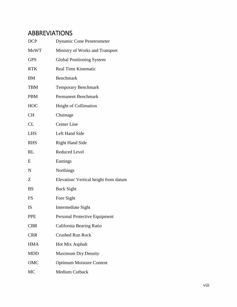
ABBREVIATIONS DCP Dynamic Cone Penetrometer
MoWT Ministry of Works and Transport
GPS Global Positioning System
RTK Real Time Kinematic
BM Benchmark
TBM Temporary Benchmark
PBM Permanent Benchmark
HOC Height of Collimation
CH Chainage
CL Center Line
LHS Left Hand Side
RHS Right Hand Side
RL Reduced Level
E Eastings
N Northings
Z Elevation/ Vertical height from datum
BS Back Sight
FS Fore Sight
IS Intermediate Sight
PPE Personal Protective Equipment
CBR California Bearing Ratio
CRR Crushed Run Rock
HMA Hot Mix Asphalt
MDD Maximum Dry Density
OMC Optimum Moisture Content
MC Medium Cutback

ix
ABSTRACT A successful industrial training is necessary for the award of a degree of a Bachelor of Science in
Civil engineering. The main aim of the training program was to expose students to a more practical
approach of theoretical concepts learnt at the university
This report depicts the activities carried out during my eight weeks, during the internship period
from 6th/June to 29th/August 2015 on the Seguku-Kasenge-Buddo (10 km) road redesign and build
project under Wakiso District Local Government (client). The project was contracted by Abubaker
Technical Services and General Supplies Limited and supervised by UB Consulting Engineers
Limited.
This report involves details of all the activities I was involved in during the internship period.
These have been separated into various sections namely; Introduction, Literature review, and
methodology.
The introduction is made up of objectives of training, brief background on the contractor and
consultant, a project setting layout, a summary of road design specifications as well as the scope
of works
Literature review was compiled on most of the aspects of the site works, from textbooks, internet
and published articles to describe some literal concepts of the works done on site and the theory
underlying most of the field practices carried out during the training. It is made up of pavement
types and properties, materials, theory behind earthworks, pavement layer construction, asphalt
concrete placement and compaction activities, drainage works and field surveying operations
Methodology including Field survey operations, Earthworks, Pavement layer construction,
asphalt works and drainage works
Field surveys involve setting out of road centerline and cross section on formation level, road
chaining, setting up pegs to assist in checking levels on constructed road and final validation works
and checks on finished layers
Earthworks are made up of the processes involved in preparing the subgrade (>95% CBR, 12m
width) for the overlying pavement layers such as grubbing, cutting and filling, rock filling at the
section in the swamp.

x
The process of pavement layer construction and asphalt concrete laying is then described as
required following the design specifications from the subbase (11m width, 170mm depth), base
(9.5m width, 150mm depth) to the wearing course (9m width, 30mm depth).
A description of several field tests carried out such DCP to determine subgrade strength (CBR
value) and bearing capacity, field density test by sand replacement method on compacted layers to
determine level of compaction of base and subbase, and nuclear density gauge tests to determine
level of compaction of asphalt concrete layer.
Drainage works involve the drainage features on site, setting out process, excavation, levelling and
finally stone pitching of the drain surfaces

1
CHAPTER ONE: INTRODUCTION This report includes a theoretical and technical account of the activities I participated in during my
eight week long industrial training from 6th June to 29th July 2016. The information in this report
is based on my personal observations, experience during participation in site activities,
consultation and the theoretical background obtained from the lecture rooms.
1.1 Background
Industrial training is an important part of training to students especially the engineering student
since it prepares the student for real work in the field.
This course introduces students to various technological skills in industries and provides on-the-
job training and exposure. It’s through this kind of training that the student is exposed to the real
application of the theoretical knowledge from the classroom to the field.
1.2 Objectives
Expose students to practical aspects of engineering and construction activities
Provide an opportunity to students to relate the knowledge obtained during lectures to
actual field operations
Create an understanding of the roles played by different project personnel during project
execution
Enable students learn how to work in a team (casual workers, technicians, engineers, etc).
Teach students different engineering ethics necessary for career building
Enhance problem solving capacity of the students using available appropriate technology
and surrounding condition
Enable students to have a hands-on with tools and equipment not readily available in the
University laboratories and are of great importance in the engineering field
Enable students appreciate various challenges faced in the field and critical areas
necessitating further research studies.

2
Create a more imaginative understanding, to students, of concepts taught in lecture rooms,
making the job of a lecturer much easier to carry out
Equip students with a feel of the work environment away from school, which may in turn
assist them during later decision making concerning aspects of study, work, and life
generally
1.3 Project Setting
The ongoing project is the “DESIGN AND BUILD OF SEGUKU-KASENGE-BUDDO
(10KM) AND LUBOWA (QUALITY SUPERMARKET) HILL VIEW ROAD (2.1KM)
WAKISO DISTRICT LOCAL GOVERNMENT LOT 1”:
CONTRACT NO. WAK1555/WRKS/2015-2016/00002
The contract agreement was made between the Wakiso District local government and Abubaker
Technical Services and General Supplies Limited (Main contractor), to carry out the project of
reconstruction /upgrading and periodic maintenance of Lubowa Quality Supermarket Hill view
Road (2.1 km) and Seguku Busawula Kasenge Buddo Road (10.0 km) LOT 1;
The project was contracted with an assigned duration of 18 months, with an expected starting date
of 26TH/03/2016 and last till 25TH/09/2017.
This project was overall estimated to cost Ushs. 15,188,224,517 ($4,467,125) fully funded by
Government of the Republic of Uganda as a rehabilitation grant.
The Figure 1 below depicts the structure of the stakeholders involved in the ongoing project, which
was deployed as the project sign board:

3
Figure 1: Project stakeholder set-up
1.3.1 Consultant’s Background
The consultants to the project are UB Consulting Engineers Ltd, established in Uganda in 2011
and is operated by indigenous Ugandans. UB Consulting Engineers Ltd. is a leading consultancy
service provider to both private and public sectors in the fields of engineering, management,
computing, architecture and surveying in East Africa, specializing in Materials and Geotechnical

4
Engineering, Structural & Bridge Engineering, Highways Engineering, Hydrology and
Hydraulics, Sociology.
Physical address:
P. O. Box 22509, Kampala | Plot 3, Nasuuna lane, Masanafu, Lugala – Rubaga division
Tel.: +256 200908255 or +256 414-581938
Email: [email protected] | www.ubconsulting.co.ug
1.3.2 Contractor’s Background
The main contractor to whom the project was awarded is Abubaker Technical Services and General
Supplies Limited, commended for its highly qualified and experienced team able to implement
complicated projects and meet the most challenging requirements.
The contractor has also been involved in some of the following projects as part of the company’s
experience:
Maintenance of Nakivubo channel section (From Jan 2008 to Dec 2009 worth Ushs.867M)
Periodic Maintenance of Nsambya and Hanlon Roads in Makindye Division (From Aug
2012 to Jan 2013 worth Ushs.3.7Bn)
Construction of Access Road to Petroleum Directorate Head Office Building in Entebbe
(March 2016 worth Ushs.1.7Bn)
Construction of Selected Infrastructure sub-projects in Mbarara Municipality (From March
2016 worth Ushs.18Bn)
And over 50 other projects have been contracted successfully by the indigenous company over the
years since 2005.
Physical address:
P.O. Box 29087 Kampala, Uganda
Telephone: +256-392-949990
Email: [email protected]
The site offices of the contractor were located at CH 2+300, offset 10m on the RHS.
5
Aims of the Project
The major aim of this project is to upgrade the existing gravel road which was ravaged by poor
drainage and has narrow sections to bituminous standards. This is owing to the considerable
increase in the volume of traffic. This will be achieved by;
Increasing the width of the road.
Implementing the geometric design for the new road, providing extra widening in corners,
super elevation and busy centers such as towns and trading centers.
Improving drainage especially in swampy areas through use of rock fill and providing
drainage conduits for example culverts, stone pitched trenches.
1.4 Road design specifications
The following design specifications shown in Table 1 below were adopted in the implementation
of the road construction for the Seguku-Kasenge-Buddo road project
PARAMETER REMARKS
Chainage 0+000 - 10+000
Location Seguku-Kasenge-Buddo
Lane Width 3.5 m
Number of lanes 2
Shoulder Width 1.0 m
Design Speed 50 km/hr
Design Life 10 years
Normal Camber (cross slope) 2.50%
1.5 Scope of works
My training on the Seguku-Kasenge-Buddo road project lasted from 7th June 2016 to 29th July
2016. I carried out my training affiliated to the consultant of the project, UB consulting engineers
Ltd.
During the 8-week internship period, I was involved in four major activities, namely:
Surveying and road setting out

6
Pavement layer construction and asphalt works
Insitu pavement layer tests
Drainage works
7
CHAPTER TWO: LITERATURE REVIEW 2.1 Pavement
A pavement is a structure made up of carefully selected and well-proportioned materials in
different layers designed to transfer loads applied to the surface so that the underlying subgrade
is not overstressed.
The major aims of pavement design are:
Structure - Provide a structure that has adequate strength to distribute the wheel
loads to the soil without undue deflection, compaction or consolidation.
Surface - Provide a surface that is adequately stable so as to not deform under traffic load,
is weather resistant, has adequate skid resistance, is adequately smooth and is
sufficiently wear resistant.
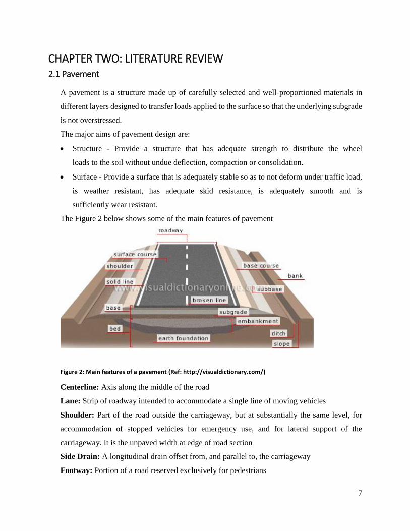
The Figure 2 below shows some of the main features of pavement
Figure 2: Main features of a pavement (Ref: http://visualdictionary.com/)
Centerline: Axis along the middle of the road
Lane: Strip of roadway intended to accommodate a single line of moving vehicles
Shoulder: Part of the road outside the carriageway, but at substantially the same level, for
accommodation of stopped vehicles for emergency use, and for lateral support of the
carriageway. It is the unpaved width at edge of road section
Side Drain: A longitudinal drain offset from, and parallel to, the carriageway
Footway: Portion of a road reserved exclusively for pedestrians
8
Subgrade: Is the formation or foundation layer, the structure that must eventually support all
loads that cone onto the pavement
Subbase: Is made up of granular material or stabilized material and it may be used in areas
where frost action is severe, where the subgrade soil is extremely weak, or where construction
working table is needed
Base: This is a layer or layers of very high stability and density. Its principal purpose is to
distribute or spread the stresses created by wheel loads acting on the wearing surface so that
the stresses transmitted to the subgrade will not result in excessive deformation foundation
layer
Road camber: The slope from a high point (typically at the center line of a road) across the
lanes of a highway. It is also called cross fall/cross slope.
Carriageway: Part of the roadway including the various traffic lanes and auxiliary lanes but
excluding shoulders
Roadway: Part of the road comprising the carriageway, shoulders and median
2.1.1 Flexible Pavement
A flexible pavement structure is typically composed of several layers of material with better
quality materials on top where the intensity of stress from traffic loads is high and lower quality
materials at the bottom where the stress intensity is low. Flexible pavements can be analyzed
as a multilayer system under loading.
When hot mix asphalt (HMA) is used as the surface course, it is the stiffest and may contribute
to the pavement strength. The underlying layers are less stiff but are still important to pavement
strength as well as drainage and frost protection (Russel W. Lenz 2011).
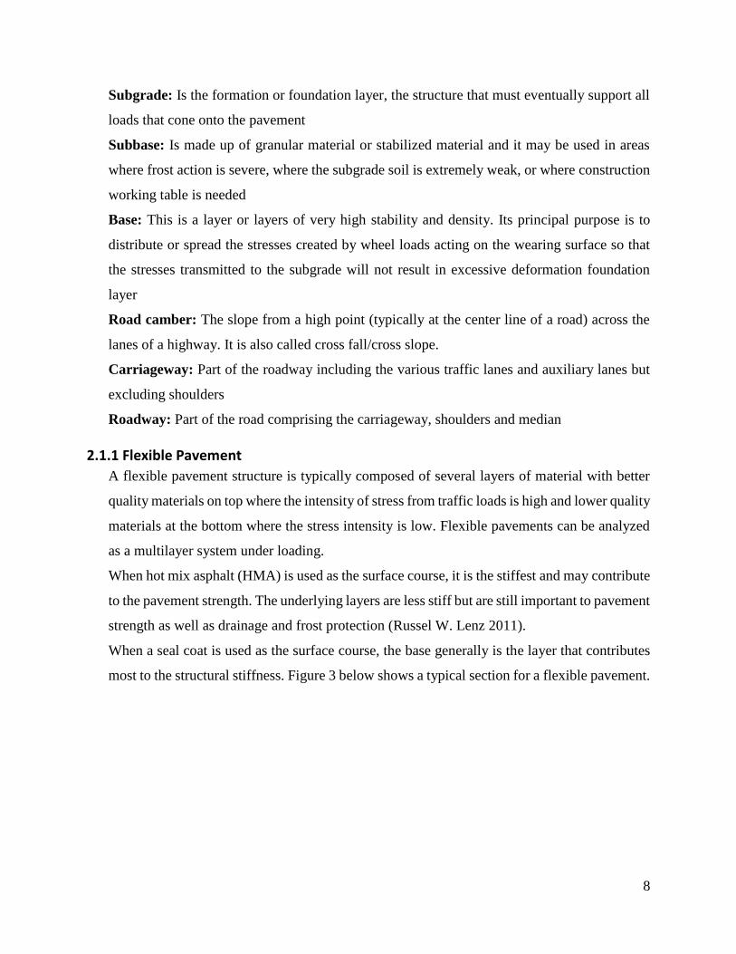
When a seal coat is used as the surface course, the base generally is the layer that contributes
most to the structural stiffness. Figure 3 below shows a typical section for a flexible pavement.
9
Figure 3: Components of flexible pavement (Ref: E-info Wiki; Civil and Environmental Engineering portal)
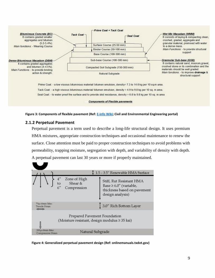
2.1.2 Perpetual Pavement
Perpetual pavement is a term used to describe a long-life structural design. It uses premium
HMA mixtures, appropriate construction techniques and occasional maintenance to renew the
surface. Close attention must be paid to proper construction techniques to avoid problems with
permeability, trapping moisture, segregation with depth, and variability of density with depth.
A perpetual pavement can last 30 years or more if properly maintained.
Figure 4: Generalized perpetual pavement design (Ref: onlinemanuals.txdot.gov)

10
Structural deterioration typically occurs due to either classical bottom-up fatigue cracking,
rutting of the HMA layers, or rutting of the subgrade. Perpetual pavement is designed to
withstand almost infinite number of axle loads without structural deterioration by limiting the
level of load-induced strain at the bottom of the HMA layers and top of the subgrade and using
deformation resistant HMA mixtures (Russel W. Lenz 2011).
2.1.3 Rigid Pavement
A rigid pavement structure is composed of a hydraulic cement concrete surface course and
underlying base and subbase courses. The surface course (concrete slab) is the stiffest layer
and provides the majority of strength. The base or subbase layers are orders of magnitude less
stiff than the PCC surface but still make important contributions to pavement drainage and
provide a working platform for construction equipment (Russel W. Lenz 2011).
A typical structure of a rigid pavement is as shown in the Figure 5 below
Rigid pavements are substantially stiffer than flexible pavements resulting in very low
deflections under loading.
Figure 5: Typical structure of rigid pavement (Ref: Highway Engineering class notes 2015)
2.1.3.1 Jointed Reinforced Concrete Pavement (JRCP)
JRCP uses contraction joints and reinforcing steel to control cracking. Transverse joint spacing
is longer than that for concrete pavement contraction design (CPCD). This rigid pavement
11
design option is no longer widely endorsed because of past difficulties in selecting effective
rehabilitation strategies (Russel W. Lenz 2011).
2.1.3.2 Concrete Pavement Contraction Design (CPCD)
Also known as the Joint Unreinforced Concrete Pavement (JUCP), CPCD uses contraction
joints to control cracking and does not use any reinforcing steel. Transverse joint spacing is
selected such that temperature and moisture stresses do not produce intermediate cracking
between joints (Russel W. Lenz 2011).
2.1.3.3 Continuously Reinforced Concrete Pavement
CRCP provides joint-free design. The formation of transverse cracks at relatively close
intervals is a distinctive characteristic of CRCP. These cracks are held tightly by the
reinforcement and should be of no concern as long as the cracks are uniformly spaced, do not
spall excessively, and a uniform non-erosive base is provided (Russel W. Lenz 2011).
2.1.4 Composite Pavement
A composite pavement is composed of both hot mix asphalt (HMA) and hydraulic cement
concrete. Typically, composite pavements are asphalt overlays on top of concrete pavements.
The HMA overlay may have been placed as the final stage of initial construction, or as part of
a rehabilitation or safety treatment. Composite pavement behavior under traffic loading is
essentially the same as rigid pavement (T.F. Fwa 2006)
2.1.5 Rigid and Flexible Pavement Characteristics
The primary structural difference between a rigid and flexible pavement is the manner in which
each type of pavement distributes traffic loads over the subgrade. A rigid pavement has a very
high stiffness and distributes loads over a relatively wide area of subgrade – a major portion
of the structural capacity is contributed by the slab itself as shown in Figure 6(b) below.
The load carrying capacity of a true flexible pavement is derived from the load-distributing
characteristics of a layered system (Yoder and Witczak, 1975) as shown in Figure 6(a) below.

12
Figure 6: Load transfer mechanism in flexible and rigid pavement (Ref: Handbook for highway engineering, T.F. Fwa)
2.2 Pavement Materials:
2.2.1 Soil
Soil is any un-cemented or weakly cemented accumulation of mineral particles formed by the
weathering of rocks, the void space between the particles containing water and/or air. (Craig,
2004). Soil is a most important part of the road structure. It is the soil that provides support to
the road from below and therefore it should possess sufficient strength and stability under most
adverse loading and climatic conditions.
Soil used in embankments should be incompressible. This will prevent differential settlement
in the sub-grade, to achieve this incompressibility the soil should be compacted and stabilized
adequately. (Singh, 2004).
Soil index properties
Types of soils vary from place to place and area to area. The index properties of soil are as
follows
Grain size distribution is in coarse grained soils and is determined by sieve analysis. For the
fine grained soils grain size distribution can be analyzed by sedimentation.
Sieve analysis process is sieving a soil sample through the set of sieves kept one over the other,
the largest sieve being at the top and the smallest at the bottom. The soil retained on each sieve
is weighed and expressed as a percentage of the total weight of the sample.
For consistency limits, atterberg’s tests are carried out to determine the consistency and plastic
behavior of the fine soils.
13
Liquid limit: It is the minimum moisture content at which the soil will flow under its own
weight when tapped 25 times in Casegrande apparatus device. This indicates the limit where
soil changes from plastic to liquid state. At this limit of moisture, the effect of cohesion and
internal friction becomes practically zero
Plastic limit: this indicates the percentage of moisture at which the soil sample changes with
decreasing wetness from a plastic to a semi-solid state. It is the maximum water content at
which soils can be rolled into threads approximately 3mm diameter without breaking.
Plastic index: the range of consistency within which soil exhibits plastic properties is called
the plastic range and it is indicated by the plastic index. Plastic index is the numerical
difference between liquid limit and plastic limit.
Shrinkage limit: it is the moisture content expressed as a percentage at which volume change
ceases.
After obtaining the soil limits, the soil is classified using Unified Soil Classification System
(USCS).
2.2.2 Aggregates:
Stone aggregate is a principle material used in pavement construction. In bituminous
pavements, aggregates constitute about 90% of the construction materials. This is the material
primarily responsible for bearing stress occurring on the road and also to resist wear due to
abrasive action of the traffic.
The aggregates are obtained from natural rock. There are soft and hard aggregates. Hard
aggregates are used to resist crushing effects and adverse weather conditions while soft
aggregates are used in gravel roads. Aggregates are specified according to their grain size,
shape, texture and gradation.
Favorable properties of aggregates
Strength
Hardness
Toughness
Soundness
Shape of aggregate
Surface texture and angularity
14
2.3 Earthworks
This refers to all soils material placed below the formation level including improved subgrade
layers, fill and prepared roadbed. It involves site investigation, clearing and grubbing,
excavation, and construction of the embankments, compaction and finishing operations.
(MWHC, 2005). The different classifications of earthworks are described below:
2.3.1 Site Investigation
A site investigation is required to determine the classification and the bearing strength of the
subgrade. The susceptibility of the subgrade to frost heave and the position of the water table
are also required. (Fwa, 2006).
Methods of investigations
Boring and probing – Involves the determination of the nature of the ground in a geological
structure and recovery of undisturbed samples for laboratory examination.
Geophysical techniques
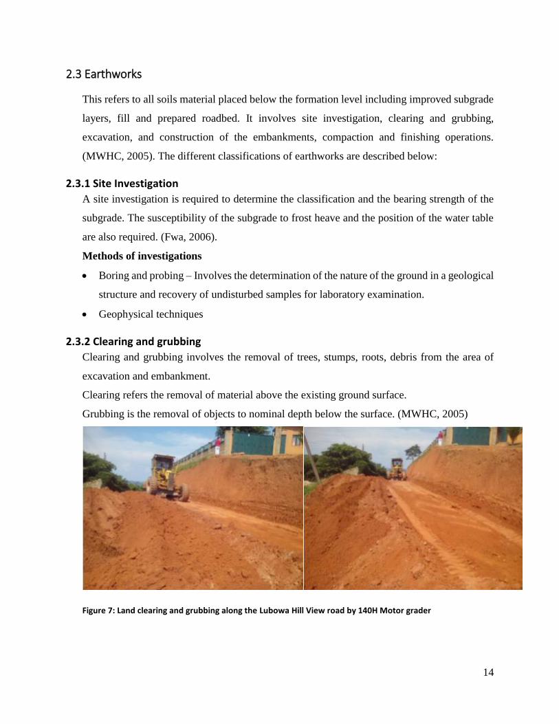
2.3.2 Clearing and grubbing
Clearing and grubbing involves the removal of trees, stumps, roots, debris from the area of
excavation and embankment.
Clearing refers the removal of material above the existing ground surface.
Grubbing is the removal of objects to nominal depth below the surface. (MWHC, 2005)
Figure 7: Land clearing and grubbing along the Lubowa Hill View road by 140H Motor grader
15
2.3.3 Excavation
Excavation is the process of loosening and removing rock or earth from its original position
and transporting it to a fill or waste deposit. Excavation involves; road and drainage
excavation, excavation for structures and borrow excavation. (MWHC, 2005)
2.3.4 Cut and fill
A cut is a section of the road where the formation level is below the original ground level
requiring excavations before the construction of the pavement layers as shown in figure 9.
A fill is a portion of a road prism consisting of approved material, which lies on the road bed
and is bounded by embankment side slopes and on which the subgrade is placed as shown
below.
2.3.5 Embankments
Embankments are used in road construction when the vertical alignment of the road has to be
raised above the level of the existing ground to satisfy the design standards, or prevent damage
from surface or ground water. Many embankments are only 0.5-1.5m high, but heights of 5m
may be used on major highways.
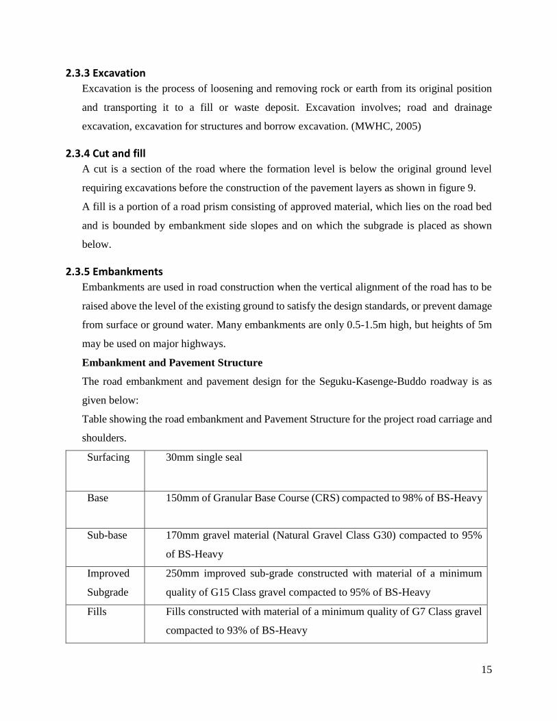
Embankment and Pavement Structure
The road embankment and pavement design for the Seguku-Kasenge-Buddo roadway is as
given below:
Table showing the road embankment and Pavement Structure for the project road carriage and
shoulders.
Surfacing 30mm single seal
Base 150mm of Granular Base Course (CRS) compacted to 98% of BS-Heavy
Sub-base 170mm gravel material (Natural Gravel Class G30) compacted to 95%
of BS-Heavy
Improved
Subgrade
250mm improved sub-grade constructed with material of a minimum
quality of G15 Class gravel compacted to 95% of BS-Heavy
Fills Fills constructed with material of a minimum quality of G7 Class gravel
compacted to 93% of BS-Heavy
16
Roadbed 150mm depth after clearing, grubbing and removal of topsoil and/or
other unsuitable material compacted to 93% of BS-Heavy.
2.4 Asphalt Concrete Works
Asphalt concrete mixes are made up of mixtures of aggregate and asphalt cement binder about
95% aggregate by weight, about 75% aggregate by volume ideally, 3-5% air voids
HMA mix designs are carried out to develop an economical blend of aggregates and asphalt
that meet design requirements using the Marshall or Hveem test
Required properties:
Flexibility due to high binder content of low viscosity
Short-term loadings elastic properties of binder-aggregate matrix
Long-term durability
Sufficient workability: Ease in which material is handled and laid and compacted
Sufficient strength and stability under traffic loads
Sufficient air voids
-Upper limit to prevent excessive environmental damage
-Lower limit to allow room for initial densification due to traffic
2.4.1 Terms used
Asphalt is the cementitious material being added as bituminous binder
Asphalt concrete is the asphalt mix in place on the road including levelling and surface courses
during and after spreading and compacting.
Asphalt Mix is the mix after the asphalt mix aggregate and asphalt have been blended together.
Asphalt Mix Design is the laboratory determination of the precise proportions of asphalt,
reclaimed asphalt concrete, additives, and all virgin aggregates to be blended together to meet
the specified properties for the asphalt mix.
Job Mix Formula is the field determination of the precise proportions of asphalt, reclaimed
asphalt concrete, additives, and all virgin aggregates to be blended together to meet the
specified properties for the asphalt mix as produced at the plant (MoWT 2010)
17
2.4.2 Pavement Surface Preparation
2.4.2.1 Surface Condition
The performance of a flexible pavement under traffic is directly related to the condition of the
surface on which the pavement layers are placed. For a full-depth asphalt pavement, if the
condition of the subgrade soil is poor, the ultimate durability of the roadway may be reduced.
For hot mix asphalt (HMA) layers placed on top of a new, untreated granular base course, the
base material should not be distorted by the trucks carrying the mix to the paver. For HMA
placed as an overlay on top of an existing HMA layer, the surface should be free of major
distresses, smooth and clean.
2.4.2.2 Prime Coat - Flexible Pavements
For flexible pavements, the graded subgrade or the top granular base layer may be prepared
with a prime coat. A prime coat is a sprayed application of a cutback (MC-30 or MC-70) or
emulsion asphalt applied to the surface of untreated subgrade or base layers. The prime coat
serves several purposes:
fills the surface voids and protect the base from weather
stabilizes the fines and preserve the base material
promotes bonding to the subsequent pavement layers.
2.4.2.3 Underseals
Existing Surface Preparation for Overlays includes an under seal which is a sprayed application
of asphalt binder (emulsion or hot applied asphalt binder) immediately covered by a layer of
one-sized aggregate. The underseal provides several benefits, such as waterproofing the
surface, sealing small cracks and protecting the underneath surface from solar radiations
2.4.2.4 Existing Surface Preparation for Overlays
The degree of surface preparation for an overlay is dependent on the condition and type of the
existing pavement. Generally, the existing pavement should be structurally sound, level, clean
and capable of bonding to the overlay. To meet these prerequisites, the existing pavement is
usually repaired, leveled, cleaned and then coated with a binding agent. This subsection covers:
repair
tack coats.
A tack coat material is an emulsion layer applied between HMA pavement lifts to promote
adequate bonding. If adjacent layers do not bond to one another they essentially behave as
18
multiple independent thin layers - none of which are designed to accommodate the anticipated
traffic-imposed bending stresses. Inadequate bonding between layers can result in
delamination (de-bonding) followed by longitudinal wheel path cracking, alligator cracking,
potholes, and other distresses such as rutting that greatly reduce pavement life.
Application
Tack coats should be applied uniformly across the entire pavement surface and result in more
than about 90% surface coverage. In order for this uniformity to be consistently achieved, all
aspects of the application must be considered and carefully controlled. Specific aspects are:
the condition of the pavement surface receiving the tack coat
the application rate
type of tack coat according to specified standards
Condition of the Pavement Surface Receiving the Tack Coat
The pavement surface receiving the tack coat should be clean and dry to promote maximum
bonding. Emulsified tack coat materials may be applied to cool and/or damp pavement
Since existing and milled pavements can be quite dirty and dusty, their surfaces should be
cleaned off by sweeping, washing or high pressure compressor blowing before any tack coat
is placed, otherwise the tack coat material may bond to the dirt and dust rather than the adjacent
pavement layers. This can result in excessive tracking of the tack coat material. Construction
vehicles and equipment pick up the tack-dirt mixture on their tires and leave the existing
roadway with little or no tack coat in the wheel paths
Application Rate
Tack coat application should result in a thin, uniform coating of tack coat material covering
approximately 90% of the pavement surface (Flexible Pavements of Ohio, 2001).
Too little tack coat can result in inadequate bonding between layers. Too much tack coat can
create a lubricated slippage plane between layers, or can cause the tack coat material to be
drawn into an overlay, negatively affecting mix properties and even creating a potential for
bleeding in thin overlays
Factors considered include:
Roughness of the pavement surface receiving the tack coat. Rough surfaces require more
tack coat than smooth surfaces.
19
Distributor vehicle. Several vehicle-related adjustments and settings are critical to
achieving uniform tack coat placement. Essentially the nozzle patterns, spray bar height
and distribution pressure must work together to produce uniform tack coat application.
Other Tack Coat Aspects considered include
Timing: Generally, a tack coat should be allowed enough time to break and set (emulsion)
before applying the next layer of hot mix asphalt (HMA).
Tracking: Tracking is the pick-up of tack coat material by vehicle tires. Tracking deposits
tack coat material on adjacent pavement surfaces. In extreme cases, tracking may deposit
enough tack coat material to distort pavement surfaces or hinder a driver's ability to
navigate (Flexible Pavements of Ohio, 2001).
Traffic on Tack Coats: Generally, traffic should not be allowed on tack coats. When a
tacked road surface is exposed to traffic, the potential exists for reduced skid resistance,
especially during wet weather (Flexible Pavements of Ohio, 2001). When tack coat
surfaces must be opened to traffic, they should be covered with stone-dust/sand to provide
friction and prevent pick-up
2.4.3 Mix Transport
Mix transport can have a large impact on flexible pavement construction quality and efficiency.
Mix characteristics such as laydown temperature, aggregate segregation and temperature (120-
150oC) differentials are largely determined by transport practices. Key considerations in mix
transport are:
truck bed cleanliness and lubrication
proper mix loading techniques in order to prevent aggregate segregation
haul distance and mix temperature
timely mix unloading and unloading of the correct mix.
If properly managed, mix transport can successfully move HMA from the production facility
to the paving site with little or no change in mix characteristics
2.4.4 Mix placement
Mix placement involves any equipment or procedures used to place the delivered HMA on the
desired surface at the desired thickness. The basic concept of the asphalt paving involves:
HMA is loaded in the front,
20
carried to the rear by a set of flight feeders (conveyor belts),
spread out by a set of augers,
then leveled and compacted by a screed.
This set of functions can be divided into two main systems; the tractor (or material feed system
and the screed.
Tractor (Material Feed System)
The tractor contains the material feed system, which accepts the HMA at the front of the paver,
moves it to the rear and spreads it out to the desired width in preparation for screed leveling
and compaction. The basic tractor components are
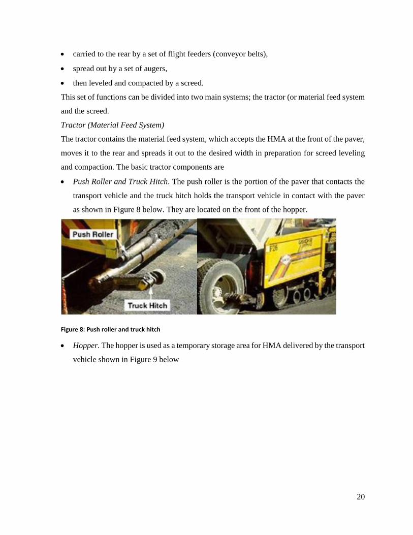
Push Roller and Truck Hitch. The push roller is the portion of the paver that contacts the
transport vehicle and the truck hitch holds the transport vehicle in contact with the paver
as shown in Figure 8 below. They are located on the front of the hopper.
Figure 8: Push roller and truck hitch
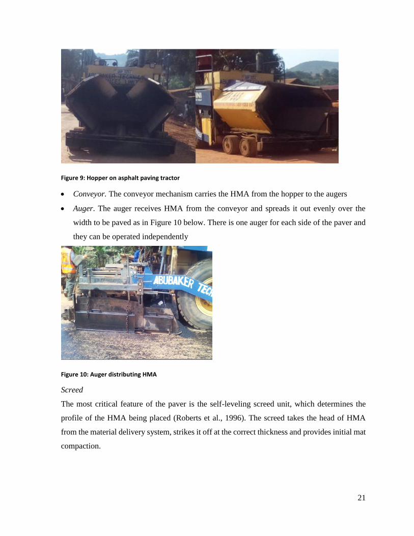
Hopper. The hopper is used as a temporary storage area for HMA delivered by the transport
vehicle shown in Figure 9 below
21
Figure 9: Hopper on asphalt paving tractor
Conveyor. The conveyor mechanism carries the HMA from the hopper to the augers
Auger. The auger receives HMA from the conveyor and spreads it out evenly over the
width to be paved as in Figure 10 below. There is one auger for each side of the paver and
they can be operated independently
Figure 10: Auger distributing HMA
Screed
The most critical feature of the paver is the self-leveling screed unit, which determines the
profile of the HMA being placed (Roberts et al., 1996). The screed takes the head of HMA
from the material delivery system, strikes it off at the correct thickness and provides initial mat
compaction.
22
2.4.5 Compaction
Compaction is the process by which the volume of air in an HMA mixture is reduced by using
external forces to reorient the constituent aggregate particles into a more closely spaced
arrangement. This reduction of air volume in a mixture produces a corresponding increase in
HMA unit weight, or density (Roberts et al., 1996).
Inadequate compaction results in a pavement with decreased stiffness, reduced fatigue life,
accelerated aging/decreased durability, rutting, raveling, and moisture damage (Hughes, 1989)
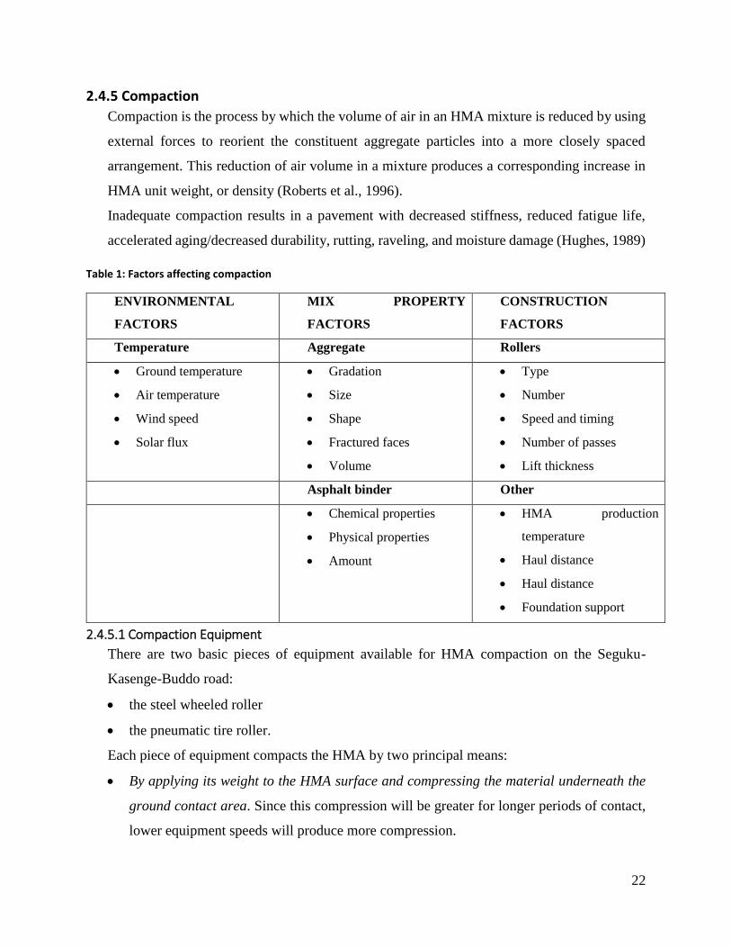
Table 1: Factors affecting compaction
ENVIRONMENTAL
FACTORS
MIX PROPERTY
FACTORS
CONSTRUCTION
FACTORS
Temperature Aggregate Rollers
Ground temperature
Air temperature
Wind speed
Solar flux
Gradation
Size
Shape
Fractured faces
Volume
Type
Number
Speed and timing
Number of passes
Lift thickness
Asphalt binder Other
Chemical properties
Physical properties
Amount
HMA production
temperature
Haul distance
Haul distance
Foundation support
2.4.5.1 Compaction Equipment
There are two basic pieces of equipment available for HMA compaction on the Seguku-
Kasenge-Buddo road:
the steel wheeled roller
the pneumatic tire roller.
Each piece of equipment compacts the HMA by two principal means:
By applying its weight to the HMA surface and compressing the material underneath the
ground contact area. Since this compression will be greater for longer periods of contact,
lower equipment speeds will produce more compression.
23
By creating a shear stress between the compressed material underneath the ground contact
area and the adjacent uncompressed material. When combined with equipment speed, this
produces a shear rate. Lowering equipment speed can decrease the shear rate, which
increases the shearing stress. Higher shearing stresses are more capable of rearranging
aggregate into denser configurations.
Steel Wheel Rollers
Steel wheel rollers are self-propelled compaction devices that use steel drums to compress the
underlying HMA. They can have one, two or even three drums, although tandem (2 drum)
rollers are most often used. The drums can be either static or vibratory
Since asphalt cement binder sticks to steel wheels, most steel wheel rollers spray water on the
drums to prevent HMA from sticking, and are equipped with a transverse bar on each drum to
wipe off HMA. This water will however cool the HMA and can reduce the time available for
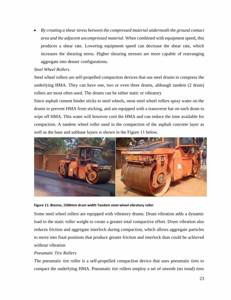
compaction. A tandem wheel roller used in the compaction of the asphalt concrete layer as
well as the base and subbase layers is shown in the Figure 11 below.
Figure 11: 8tonne, 1500mm drum width Tandem steel wheel vibratory roller
Some steel wheel rollers are equipped with vibratory drums. Drum vibration adds a dynamic
load to the static roller weight to create a greater total compactive effort. Drum vibration also
reduces friction and aggregate interlock during compaction, which allows aggregate particles
to move into final positions that produce greater friction and interlock than could be achieved
without vibration
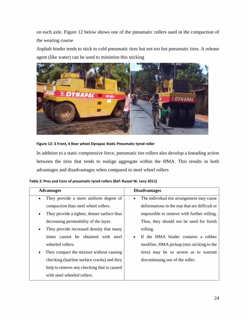
Pneumatic Tire Rollers
The pneumatic tire roller is a self-propelled compaction device that uses pneumatic tires to
compact the underlying HMA. Pneumatic tire rollers employ a set of smooth (no tread) tires
24
on each axle. Figure 12 below shows one of the pneumatic rollers used in the compaction of
the wearing course
Asphalt binder tends to stick to cold pneumatic tires but not too hot pneumatic tires. A release
agent (like water) can be used to minimize this sticking
Figure 12: 3 Front, 4 Rear wheel Dynapac Static Pneumatic tyred roller
In addition to a static compressive force, pneumatic tire rollers also develop a kneading action
between the tires that tends to realign aggregate within the HMA. This results in both
advantages and disadvantages when compared to steel wheel rollers
Table 2: Pros and Cons of pneumatic tyred rollers (Ref: Russel W. Lenz 2011)
Advantages Disadvantages
They provide a more uniform degree of
compaction than steel wheel rollers.
They provide a tighter, denser surface thus
decreasing permeability of the layer.
They provide increased density that many
times cannot be obtained with steel
wheeled rollers.
They compact the mixture without causing
checking (hairline surface cracks) and they
help to remove any checking that is caused
with steel wheeled rollers.
The individual tire arrangement may cause
deformations in the mat that are difficult or
impossible to remove with further rolling.
Thus, they should not be used for finish
rolling.
If the HMA binder contains a rubber
modifier, HMA pickup (mix sticking to the
tires) may be so severe as to warrant
discontinuing use of the roller.
25
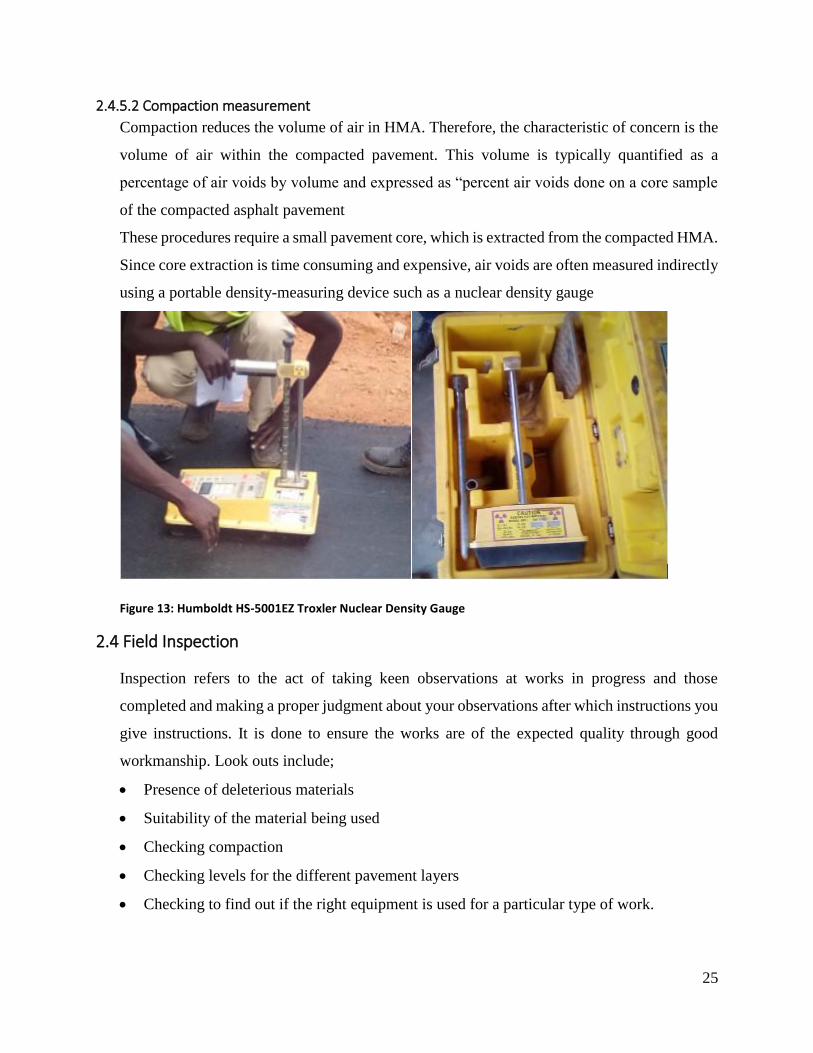
2.4.5.2 Compaction measurement
Compaction reduces the volume of air in HMA. Therefore, the characteristic of concern is the
volume of air within the compacted pavement. This volume is typically quantified as a
percentage of air voids by volume and expressed as “percent air voids done on a core sample
of the compacted asphalt pavement
These procedures require a small pavement core, which is extracted from the compacted HMA.
Since core extraction is time consuming and expensive, air voids are often measured indirectly
using a portable density-measuring device such as a nuclear density gauge
Figure 13: Humboldt HS-5001EZ Troxler Nuclear Density Gauge
2.4 Field Inspection
Inspection refers to the act of taking keen observations at works in progress and those
completed and making a proper judgment about your observations after which instructions you
give instructions. It is done to ensure the works are of the expected quality through good
workmanship. Look outs include;
Presence of deleterious materials
Suitability of the material being used
Checking compaction
Checking levels for the different pavement layers
Checking to find out if the right equipment is used for a particular type of work.
26
2.5 Drainage Structures
Drainage is very important both in relation to road pavement construction and maintenance.
This is the provision made for protecting the road from surface water or sub surface water. If
water is allowed to enter the structure of the road, the pavement will be weakened and will be
much susceptible to damage by traffic
2.5.1 Objective of Drainage
The main objective of drainage is to protect the project road and the adjacent lands against
potential damage from storm water and sub-surface water.
A good drainage system, properly maintained, is vital to the successful operation of a road. It
serves the following purpose;
To convey storm water from the surface of the carriageway to outfalls;
To control the level of the water table in the sub-grade beneath the carriageway;
To intercept ground and surface water flowing towards the road.
2.5.2 Hydraulic Structures
Hydraulic structures in roads include; bridges, box and pipe culverts, side drains, and catch
water drains.
A culvert is a specific type of stream crossing, used generally to convey water flow through
the road prism base. These usually consists of concrete, PVC or steel pipes, or a reinforced
concrete box, placed under the road within an embankment to provide suitable means of
conveying streams, or the contents of side drains under the road with no restrictions on traffic.
The most common shape used is circular, rectangular or square.
On this project, the bigger percentage of the culverts to be used was made of concrete diameter
of 900 mm.
2.5.3 Terms used
Culvert entrance: The downstream end of a culvert through which water enter to pass
upstream.
Culvert Exit: The upstream end of a culvert through which water exit to pass upstream
Culvert Inlet: The upstream end of a culvert through which stream flow enters.
Culvert Outlet: The downstream end of a culvert through which stream flow discharges.
Culvert End Structures
27
The Culvert End Structures includes; Head and Wing walls, Aprons, Catch basins and Drop
Inlets. The details of these structures are given below;
Headwall is a concrete, gabion, masonry, or timber wall built around the inlet or outlet of a
drainage pipe or structure to increase inlet flow capacity, reduce risk of debris damage, retain
the fill material and minimize scour around the structure.
Wing wall is a masonry or concrete structures built onto the side of culvert inlet and outlet
headwalls, designed to retain the roadway fill and direct water into and out of the drainage
structure while protecting the road and fill from erosion.
Apron is an extension of the head wall structure built at ground or stream level and designed
to protect the stream bottom from high flow velocities and to safely move water away from the
drainage structure.
Catch Basin - The excavated or constructed basin at the inlet of a culvert cross-drain pipe,
used to store water and direct it into the culvert pipe.
Drop Inlet - Masonry or concrete basin, or a vertical riser on a metal culvert inlet, usually of
the same diameter as the culvert, and often slotted, to allow water to flow into the culvert as
water flow rises around the outside. Drop inlets are often used on ditch relief culverts where
sediment or debris would plug the pipe. A drop inlet also helps control the elevation
2.5.4 Drainage of a Pavement
This is the process of interception and removal of water from over, under and the vicinity of
the pavement. Pavement performance and integrity often depends on the removal of water from
above and below the pavement surface. The principle function of highway drainage is to
remove surface water as rapidly and efficiently as possible from impermeable surfaces. (Fwa,
2006)
Drainage of the pavement has two main components namely:
Surface drainage,
Sub-surface drainage.
Surface water can enter the pavement construction through the porous surface, through cracks
that develop as the pavement ages and at the end of the carriage way if it cannot find its way
off the pavement. The following provisions ensure satisfactory surface drainage such that the
service life of the road is not reduced by the damage that can be inflicted by poor drainage on
the road;
28
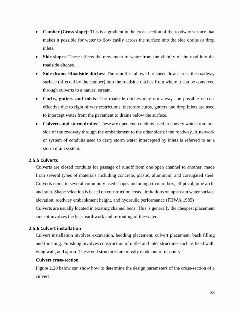
Camber (Cross slope): This is a gradient in the cross section of the roadway surface that
makes it possible for water to flow easily across the surface into the side drains or drop
inlets.
Side slopes: These effects the movement of water from the vicinity of the road into the
roadside ditches.
Side drains /Roadside ditches: The runoff is allowed to sheet flow across the roadway
surface (affected by the camber) into the roadside ditches from where it can be conveyed
through culverts to a natural stream.
Curbs, gutters and inlets: The roadside ditches may not always be possible or cost
effective due to right of way restrictions, therefore curbs, gutters and drop inlets are used
to intercept water from the pavement to drains below the surface.
Culverts and storm drains: These are open end conduits used to convey water from one
side of the roadway through the embankment to the other side of the roadway. A network
or system of conduits used to carry storm water intercepted by inlets is referred to as a
storm drain system.
2.5.5 Culverts
Culverts are closed conduits for passage of runoff from one open channel to another, made
from several types of materials including concrete, plastic, aluminum, and corrugated steel.
Culverts come in several commonly used shapes including circular, box, elliptical, pipe arch,
and arch. Shape selection is based on construction costs, limitations on upstream water surface
elevation, roadway embankment height, and hydraulic performance (FHWA 1985)
Culverts are usually located in existing channel beds. This is generally the cheapest placement
since it involves the least earthwork and re-routing of the water.
2.5.6 Culvert installation
Culvert installation involves excavation, bedding placement, culvert placement, back filling
and finishing. Finishing involves construction of outlet and inlet structures such as head wall,
wing wall, and apron. These end structures are mostly made out of masonry
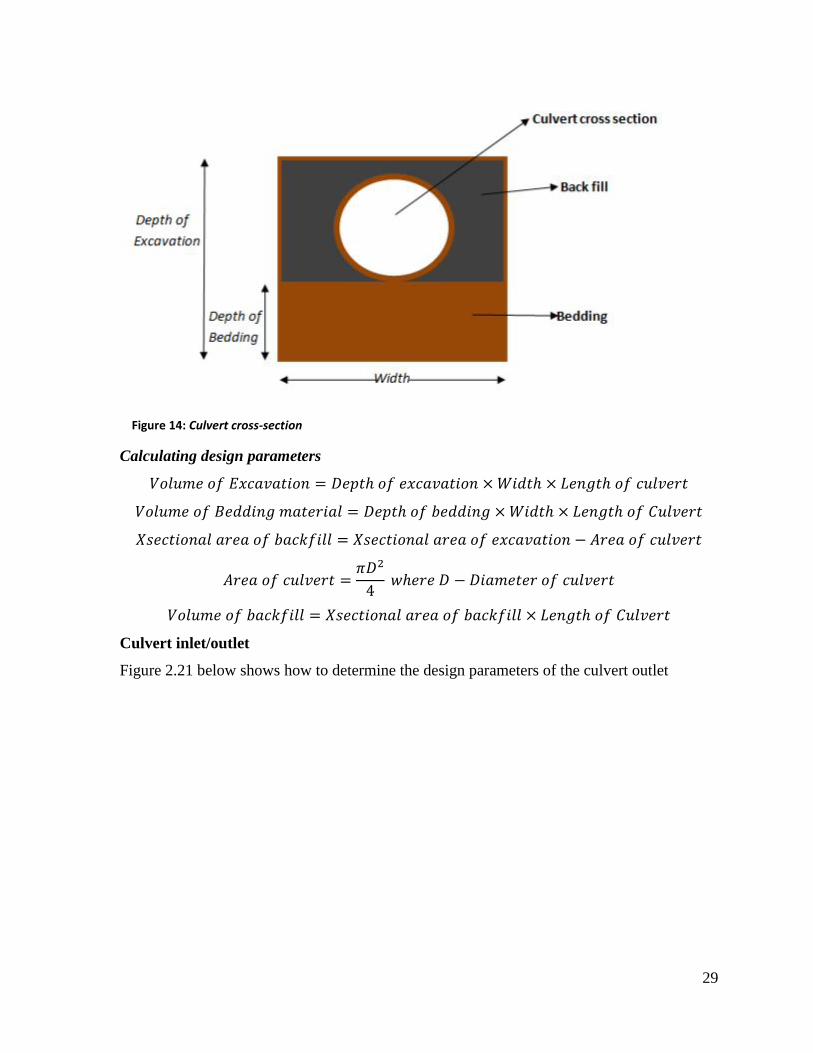
Culvert cross-section
Figure 2.20 below can show how to determine the design parameters of the cross-section of a
culvert
29
Figure 14: Culvert cross-section
Calculating design parameters
𝑉𝑜𝑙𝑢𝑚𝑒 𝑜𝑓 𝐸𝑥𝑐𝑎𝑣𝑎𝑡𝑖𝑜𝑛 = 𝐷𝑒𝑝𝑡ℎ 𝑜𝑓 𝑒𝑥𝑐𝑎𝑣𝑎𝑡𝑖𝑜𝑛 × 𝑊𝑖𝑑𝑡ℎ × 𝐿𝑒𝑛𝑔𝑡ℎ 𝑜𝑓 𝑐𝑢𝑙𝑣𝑒𝑟𝑡
𝑉𝑜𝑙𝑢𝑚𝑒 𝑜𝑓 𝐵𝑒𝑑𝑑𝑖𝑛𝑔 𝑚𝑎𝑡𝑒𝑟𝑖𝑎𝑙 = 𝐷𝑒𝑝𝑡ℎ 𝑜𝑓 𝑏𝑒𝑑𝑑𝑖𝑛𝑔 × 𝑊𝑖𝑑𝑡ℎ × 𝐿𝑒𝑛𝑔𝑡ℎ 𝑜𝑓 𝐶𝑢𝑙𝑣𝑒𝑟𝑡
𝑋𝑠𝑒𝑐𝑡𝑖𝑜𝑛𝑎𝑙 𝑎𝑟𝑒𝑎 𝑜𝑓 𝑏𝑎𝑐𝑘𝑓𝑖𝑙𝑙 = 𝑋𝑠𝑒𝑐𝑡𝑖𝑜𝑛𝑎𝑙 𝑎𝑟𝑒𝑎 𝑜𝑓 𝑒𝑥𝑐𝑎𝑣𝑎𝑡𝑖𝑜𝑛 − 𝐴𝑟𝑒𝑎 𝑜𝑓 𝑐𝑢𝑙𝑣𝑒𝑟𝑡
𝐴𝑟𝑒𝑎 𝑜𝑓 𝑐𝑢𝑙𝑣𝑒𝑟𝑡 =𝜋𝐷2
4 𝑤ℎ𝑒𝑟𝑒 𝐷 − 𝐷𝑖𝑎𝑚𝑒𝑡𝑒𝑟 𝑜𝑓 𝑐𝑢𝑙𝑣𝑒𝑟𝑡
𝑉𝑜𝑙𝑢𝑚𝑒 𝑜𝑓 𝑏𝑎𝑐𝑘𝑓𝑖𝑙𝑙 = 𝑋𝑠𝑒𝑐𝑡𝑖𝑜𝑛𝑎𝑙 𝑎𝑟𝑒𝑎 𝑜𝑓 𝑏𝑎𝑐𝑘𝑓𝑖𝑙𝑙 × 𝐿𝑒𝑛𝑔𝑡ℎ 𝑜𝑓 𝐶𝑢𝑙𝑣𝑒𝑟𝑡
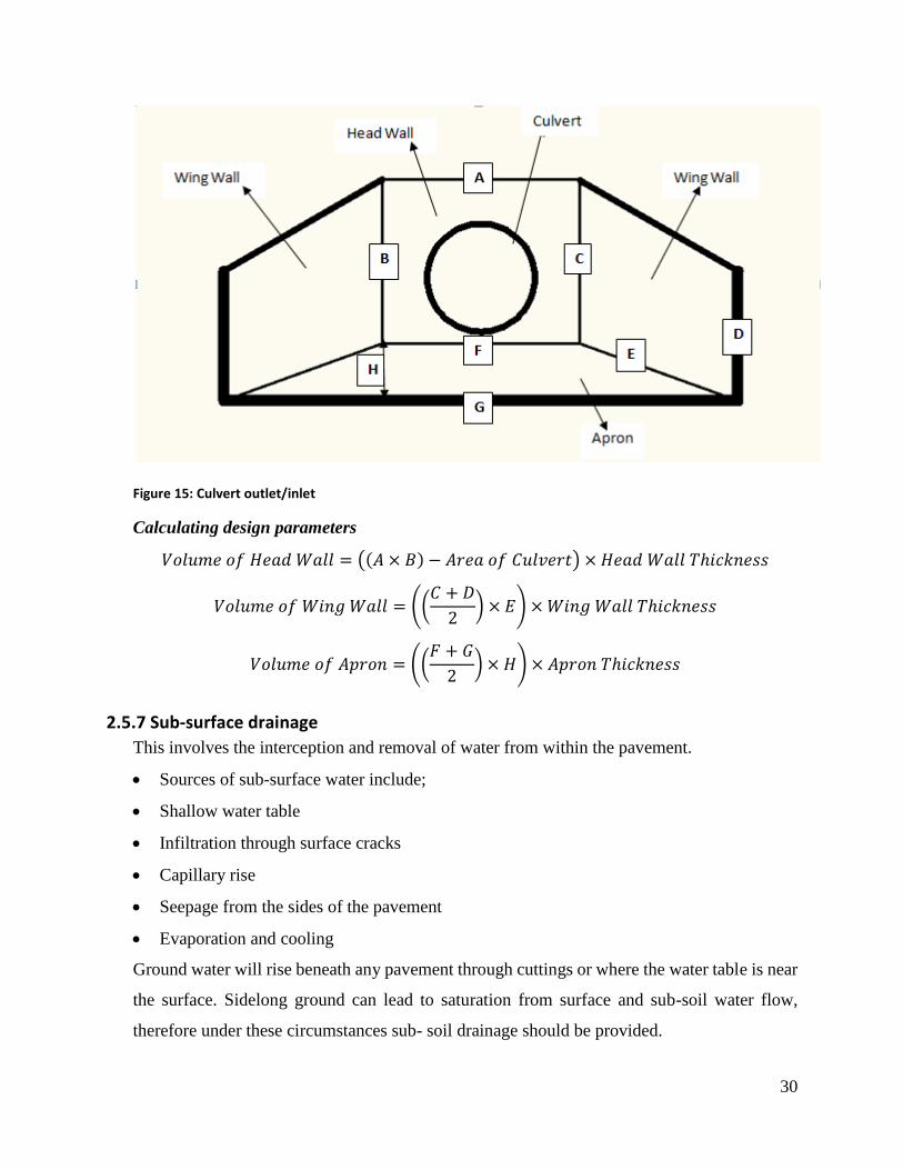
Culvert inlet/outlet
Figure 2.21 below shows how to determine the design parameters of the culvert outlet
30
Figure 15: Culvert outlet/inlet
Calculating design parameters
𝑉𝑜𝑙𝑢𝑚𝑒 𝑜𝑓 𝐻𝑒𝑎𝑑 𝑊𝑎𝑙𝑙 = ((𝐴 × 𝐵) − 𝐴𝑟𝑒𝑎 𝑜𝑓 𝐶𝑢𝑙𝑣𝑒𝑟𝑡) × 𝐻𝑒𝑎𝑑 𝑊𝑎𝑙𝑙 𝑇ℎ𝑖𝑐𝑘𝑛𝑒𝑠𝑠
𝑉𝑜𝑙𝑢𝑚𝑒 𝑜𝑓 𝑊𝑖𝑛𝑔 𝑊𝑎𝑙𝑙 = ((𝐶 + 𝐷
2) × 𝐸) × 𝑊𝑖𝑛𝑔 𝑊𝑎𝑙𝑙 𝑇ℎ𝑖𝑐𝑘𝑛𝑒𝑠𝑠
𝑉𝑜𝑙𝑢𝑚𝑒 𝑜𝑓 𝐴𝑝𝑟𝑜𝑛 = ((𝐹 + 𝐺
2) × 𝐻) × 𝐴𝑝𝑟𝑜𝑛 𝑇ℎ𝑖𝑐𝑘𝑛𝑒𝑠𝑠
2.5.7 Sub-surface drainage
This involves the interception and removal of water from within the pavement.
Sources of sub-surface water include;
Shallow water table
Infiltration through surface cracks
Capillary rise
Seepage from the sides of the pavement
Evaporation and cooling
Ground water will rise beneath any pavement through cuttings or where the water table is near
the surface. Sidelong ground can lead to saturation from surface and sub-soil water flow,
therefore under these circumstances sub- soil drainage should be provided.
31
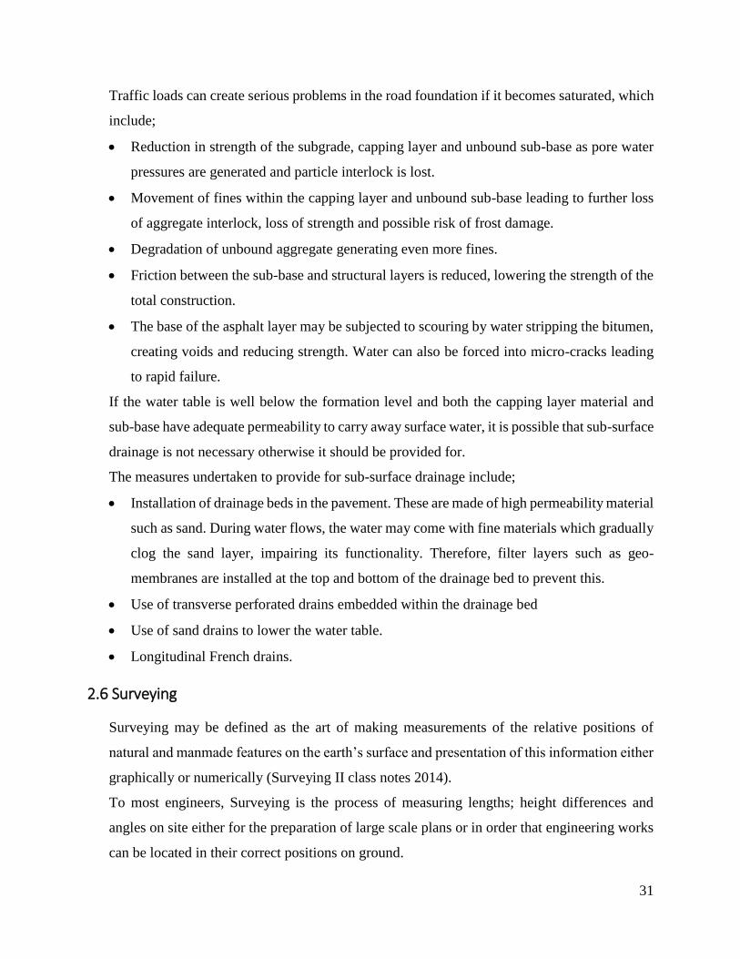
Traffic loads can create serious problems in the road foundation if it becomes saturated, which
include;
Reduction in strength of the subgrade, capping layer and unbound sub-base as pore water
pressures are generated and particle interlock is lost.
Movement of fines within the capping layer and unbound sub-base leading to further loss
of aggregate interlock, loss of strength and possible risk of frost damage.
Degradation of unbound aggregate generating even more fines.
Friction between the sub-base and structural layers is reduced, lowering the strength of the
total construction.
The base of the asphalt layer may be subjected to scouring by water stripping the bitumen,
creating voids and reducing strength. Water can also be forced into micro-cracks leading
to rapid failure.
If the water table is well below the formation level and both the capping layer material and
sub-base have adequate permeability to carry away surface water, it is possible that sub-surface
drainage is not necessary otherwise it should be provided for.
The measures undertaken to provide for sub-surface drainage include;
Installation of drainage beds in the pavement. These are made of high permeability material
such as sand. During water flows, the water may come with fine materials which gradually
clog the sand layer, impairing its functionality. Therefore, filter layers such as geo-
membranes are installed at the top and bottom of the drainage bed to prevent this.
Use of transverse perforated drains embedded within the drainage bed
Use of sand drains to lower the water table.
Longitudinal French drains.
2.6 Surveying
Surveying may be defined as the art of making measurements of the relative positions of
natural and manmade features on the earth’s surface and presentation of this information either
graphically or numerically (Surveying II class notes 2014).
To most engineers, Surveying is the process of measuring lengths; height differences and
angles on site either for the preparation of large scale plans or in order that engineering works
can be located in their correct positions on ground.
32
Land surveys can also be classified by purpose as follows:
a) Topographic surveys: Used to establish the position and shape of natural and manmade
features over a given area usually for purposes of producing a map of an area
Such surveys are normally classified according to the scale of the final map. Typical scales
are: 1:1000000, 1:50000, 1:10000, 1:1000, 1:500 etc.
b) Cadastral surveys: Undertaken to produce plans of property boundaries for legal purposes.
For instance, in many countries the registration of land ownership is based on cadastral
surveys/plans
c) Engineering surveys: Embrace all the survey work required before, during and after any
engineering works.
d) Hydrographic surveying: Carried out on water bodies like lakes, rivers and oceans. They
involve measuring water depth and investigating the nature of the sea bed in order to
produce navigational charts for mariners. Other uses of hydrographic surveys include:
offshore oil exploration and production, design, construction and maintenance of harbors
and inland water routes, scientific studies etc.
2.6.1 Major survey operations
i) Setting out – This describes the process of establishing on paper designs on ground.
Involves making an alignment for the proposed road using survey equipment. It comprises
pegging out the route, and establishing the width and level of the road.
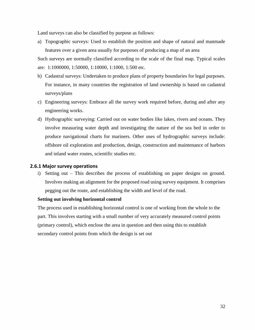
Setting out involving horizontal control
The process used in establishing horizontal control is one of working from the whole to the
part. This involves starting with a small number of very accurately measured control points
(primary control), which enclose the area in question and then using this to establish
secondary control points from which the design is set out

33
Figure 16: Setting out involving horizontal control
Once established and coordinated, control points can be used with a positioning technique to
set out E, N coordinates of the design points of the proposed structure. They are generally used
following the road centerline as the baseline.
Setting out involving vertical control
To provide a basis for vertical control, all levels on site will normally be reduced to a nearby
Benchmark (BM). The actual BM used is normally agreed upon by the engineer and the
contractor and is termed as the Master Benchmark (MBM). This is used for two main
purposes;
To establish points of known reduced level near to and on the elements of the
proposed scheme i.e. Temporary Bench marks (TBMs).
Used to check the reduced level of any nearby BMs and in case of any
discrepancy, their amended values are used.
When coordinated points are set out for horizontal control, the points are often leveled with
reference to either the MBM or TBM to provide vertical control
ii) Leveling – Involves determining the relative difference in elevation between two or more
points by measuring from the ground level to the line of collimation.
iii) Tape and offsetting – Often referred to as chain surveying deriving its name from the fact
that the principal item of equipment traditionally was a measuring chain which has been
replaced by an accurate steel band. (Bannister and Raymond 1998)
34
2.6.2 Surveying terms
Offset: A distance measured perpendicular from the main line of measurement/ a side shoot
measured from the centerline
Benchmark: A height reference point or mark of known level
Line of collimation: Optical axis of a telescope: also the line of sight through an instrument
when set horizontal
Datum: Horizontal, vertical or 3-dimensional coordinate reference definition
Formation level: Excavation level (height) on which permanent works constructed
Profile: A site marker delineating the shape/level etc of a construction element at that location
Total station: A combined distance and angle (electronic) measuring survey instrument
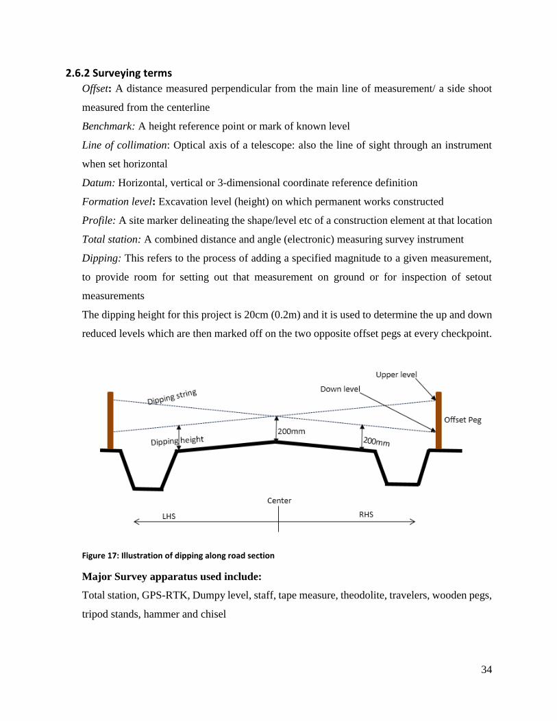
Dipping: This refers to the process of adding a specified magnitude to a given measurement,
to provide room for setting out that measurement on ground or for inspection of setout
measurements
The dipping height for this project is 20cm (0.2m) and it is used to determine the up and down
reduced levels which are then marked off on the two opposite offset pegs at every checkpoint.
Figure 17: Illustration of dipping along road section
Major Survey apparatus used include:
Total station, GPS-RTK, Dumpy level, staff, tape measure, theodolite, travelers, wooden pegs,
tripod stands, hammer and chisel
35
CHAPTER THREE: PRACTICAL WORKS 3.1 FIELD SURVEY OPERATIONS
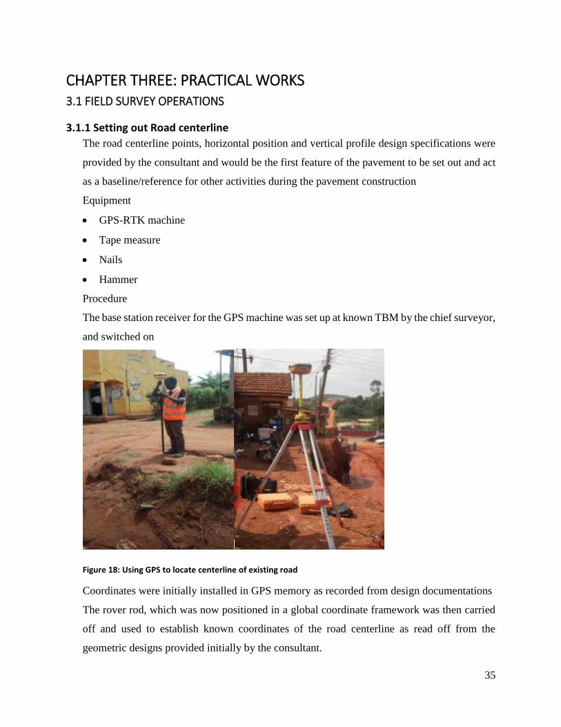
3.1.1 Setting out Road centerline
The road centerline points, horizontal position and vertical profile design specifications were
provided by the consultant and would be the first feature of the pavement to be set out and act
as a baseline/reference for other activities during the pavement construction
Equipment
GPS-RTK machine
Tape measure
Nails
Hammer
Procedure
The base station receiver for the GPS machine was set up at known TBM by the chief surveyor,
and switched on
Figure 18: Using GPS to locate centerline of existing road
Coordinates were initially installed in GPS memory as recorded from design documentations
The rover rod, which was now positioned in a global coordinate framework was then carried
off and used to establish known coordinates of the road centerline as read off from the
geometric designs provided initially by the consultant.
36
Along the movement of the rover rod, a known point was traced on the ground, located with
position by accurately horizontally adjusting the rover, until fairly accurate focus was
achieved, with the aid of variable tones of the sounding alarm.
At this centerline point, a nail was hammered into the ground to mark the location of the point
Referring to the same BM location of the base station receiver, points along the entire road
centerline were established at 20m intervals as provided in the geometric designs
3.1.2 Setting out subgrade transverse dimensions
The subgrade cross section, was obtained by use of the marked out centerline and section
details from the provided geometric designs. This was to help determine the cross dimensions
to be cut and levelled for subgrade construction
Equipment
Wooden pegs
Tape measure
Hammer
Chisel
Procedure
Using a tape measure, a distance of 6m was offset from the initially established centerline
points, measured perpendicular to the longitudinal centerline outline, on both the LHS and
RHS to obtain a 12m wide subgrade section
At each of these offsets, a wooden peg was driven into the ground to demarcate the transverse
dimensions of the road section. A chisel was used to create a hole in the ground in cases where
the ground was too hard to be penetrated by wooden peg alone
3.1.3 Road chaining
This involved writing out chainage numbers along road length as established in the initial
surveying activities. This was done with the main aim of providing labels along the road length,
which would in turn ease locating specified points along the road in the field, most especially
during inspection and further surveys.
Equipment
Weather resistant, visually clear paint (white)
Tape measure
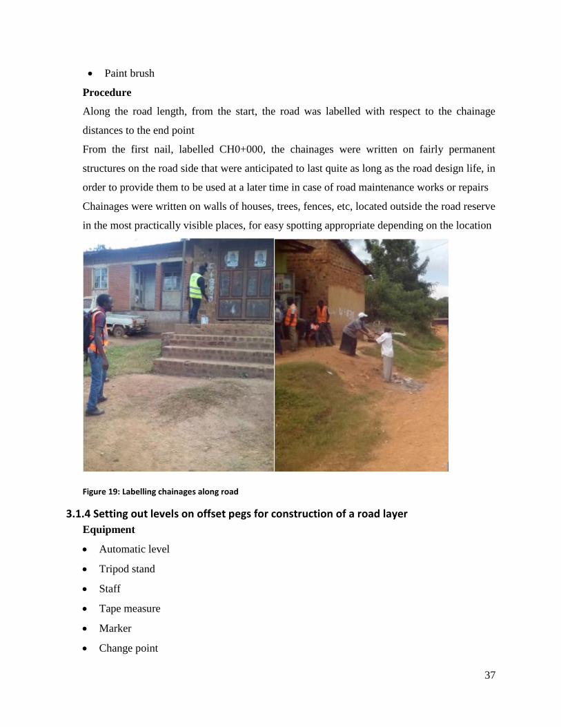
37
Paint brush
Procedure
Along the road length, from the start, the road was labelled with respect to the chainage
distances to the end point
From the first nail, labelled CH0+000, the chainages were written on fairly permanent
structures on the road side that were anticipated to last quite as long as the road design life, in
order to provide them to be used at a later time in case of road maintenance works or repairs
Chainages were written on walls of houses, trees, fences, etc, located outside the road reserve
in the most practically visible places, for easy spotting appropriate depending on the location
Figure 19: Labelling chainages along road
3.1.4 Setting out levels on offset pegs for construction of a road layer
Equipment
Automatic level
Tripod stand
Staff
Tape measure
Marker
Change point
38
Procedure
The automatic level was setup on the tripod stand at a convenient height, centered, leveled and
focused.
A BS reading was taken on a known nearby BM and the height of collimation (HOC)
calculated.
𝐻𝑂𝐶 = 𝐵𝑆 + 𝑅𝐿 𝑜𝑓 𝐵𝑒𝑛𝑐ℎ𝑚𝑎𝑟𝑘
The required down and up staff readings (including 0.2m for dipping) were calculated from;
𝑅𝑒𝑞𝑢𝑖𝑟𝑒𝑑 𝑢𝑝 𝑜𝑟 𝑑𝑜𝑤𝑛 𝑠𝑡𝑎𝑓𝑓𝑟𝑒𝑎𝑑𝑖𝑛𝑔
= 𝐻𝑂𝐶 − 𝐷𝑒𝑠𝑖𝑔𝑛 𝑢𝑝 𝑜𝑟 𝑑𝑜𝑤𝑛 𝑅𝐿 (𝑖𝑛𝑐𝑙𝑢𝑑𝑖𝑛𝑔 20𝑐𝑚 𝑑𝑖𝑝𝑝𝑖𝑛𝑔)
The staff was then held by the chainman on top of the peg, and then oriented vertically along
the length of the peg until the required staff reading was observed through the automatic level
The point at the bottom of the staff was then marked on the two pegs at each chainage using a
marker.
Change points were made after every appropriate distance, approximately 30m to ensure
intervisibility between points of sight
A foresight (FS) was then taken on a nearby benchmark as a check at the end of the survey, to
check for the margin of error.
3.1.5 Checking levels on pegs
Equipment
Automatic level,
Tripod
Calibrated staff
Procedure
The instrument (automatic level) was setup at a convenient height, centered, leveled and
focused.
A back sight (BS) reading was taken on a leveling staff held vertically at a benchmark (known
reduced level) and the height of the height of collimation (H.O.C) calculated from,
𝐻𝑂𝐶 = 𝐵𝑆 + 𝑅𝐿 𝑜𝑓 𝐵𝑒𝑛𝑐ℎ𝑚𝑎𝑟𝑘
The required upper and down staff readings (including 0.2m for dipping) to be checked for
were calculated from,
39
𝑅𝑒𝑞𝑢𝑖𝑟𝑒𝑑 𝑢𝑝 𝑜𝑟 𝑑𝑜𝑤𝑛 𝑠𝑡𝑎𝑓𝑓𝑟𝑒𝑎𝑑𝑖𝑛𝑔
= 𝐻𝑂𝐶 − 𝐷𝑒𝑠𝑖𝑔𝑛 𝑢𝑝 𝑜𝑟 𝑑𝑜𝑤𝑛 𝑅𝐿 (𝑖𝑛𝑐𝑙𝑢𝑑𝑖𝑛𝑔 20𝑐𝑚 𝑑𝑖𝑝𝑝𝑖𝑛𝑔)
Intermediate sights (IS) were taken on the already marked up and down levels on the pegs on
both the Left Hand Side (L.H.S) and Right Hand Side (R.H.S) of each marked peg checkpoint
to check whether they corresponded with the calculated required up/down staff readings and
the necessary corrections made using a marker.
The leveling staff would be held in contact with face of the peg and the chainman would be
directed by the surveyor to move the staff up and down until the calculated staff readings were
in focus at the cross hairs.
A foresight (FS) reading was taken on a nearby benchmark as a check that is,
𝑅𝑒𝑑𝑢𝑐𝑒𝑑 𝑙𝑒𝑣𝑒𝑙 𝑜𝑓 𝑏𝑒𝑛𝑐ℎ𝑚𝑎𝑟𝑘 = 𝐻𝑂𝐶 − 𝐹𝑆
3.1.6 Checking ground levels for finished road layers
This was done to ensure that the levels achieved during construction of the road layer
corresponded to those provided in the designs provided by the consultant.
Equipment
Automatic level
Tripod
Leveling staff
Fiber tape measure,
Change point (CP)
Nails.
Procedure
The instrument was setup on a tripod stand at a convenient height, centered, leveled and
focused.
A back sight (BS) reading was taken to a leveling staff held vertically at a nearby benchmark
and the height of collimation (H.O.C) calculated.
𝐻𝑂𝐶 = 𝐵𝑆 + 𝑅𝐿 𝑜𝑓 𝐵𝑒𝑛𝑐ℎ𝑚𝑎𝑟𝑘
Intermediate sights (IS) were taken along each chainage on the L.H.S and R.H.S at points
defining the end of the carriageway and shoulder as well as the centerline.
The reduced levels of these five points were calculated for every chainage from,
40
𝑅𝑒𝑑𝑢𝑐𝑒𝑑 𝑙𝑒𝑣𝑒𝑙 = 𝐻𝑂𝐶 − 𝐼𝑆
These measured reduced levels were compared with the design values for these five points
along each chainage and the discrepancy/error between the corresponding readings calculated
from,
𝐸𝑟𝑟𝑜𝑟 = 𝐷𝑒𝑠𝑖𝑔𝑛 𝑅𝐿 − 𝑀𝑒𝑎𝑠𝑢𝑟𝑒𝑑 𝑅𝐿
Therefore, a positive error indicates a fill (material should be brought and compacted in that
section to make up for the difference) and a negative difference indicates a cut (material should
be cut away from the section).
Requirements
The allowable difference was +/-20mm (0.02m)
3.1.7 Setting out the centerline on a finished road layer
The purpose of setting out centers on a finished road layer is to enable the placement of offset
pegs for construction of the next layer and they are also used in taking cross-sections/layouts
along chainage.
Equipment
Total station,
Rod with reflector prism,
Steel tape,
Tripod, nails,
Metallic hammer
Procedure
The total station was set up on the tripod stand at a convenient height, centered, leveled and
focused. The instrument was traversed on the nearby benchmark as a check.
For each chainage, the horizontal angle was set to 0°00’00’’ and the instrument fixed.
The rod with reflector prism was then moved to and fro in the road way by a chainman directed
by the surveyor looking through the telescope until the horizontal distance reading on the
screen of the instrument was 0.00m.
These points were marked on ground using nails and these were the points forming the
centerline of the road way between chainages under investigation.
The instrument was then traversed on a nearby benchmark (FS) as a check.
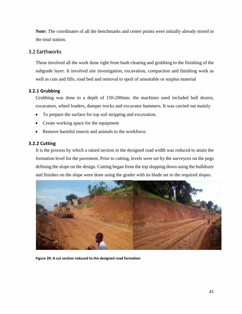
41
Note: The coordinates of all the benchmarks and center points were initially already stored in
the total station.
3.2 Earthworks
These involved all the work done right from bush clearing and grubbing to the finishing of the
subgrade layer. It involved site investigation, excavation, compaction and finishing work as
well as cuts and fills, road bed and removal to spoil of unsuitable or surplus material
3.2.1 Grubbing
Grubbing was done to a depth of 150-200mm. the machines used included bull dozers,
excavators, wheel loaders, dumper trucks and excavator hammers. It was carried out mainly
To prepare the surface for top soil stripping and excavation.
Create working space for the equipment
Remove harmful insects and animals to the workforce.
3.2.2 Cutting
It is the process by which a raised section in the designed road width was reduced to attain the
formation level for the pavement. Prior to cutting, levels were set by the surveyors on the pegs
defining the slope on the design. Cutting began from the top slopping down using the bulldozer
and finishes on the slope were done using the grader with its blade set to the required slopes.
Figure 20: A cut section reduced to the designed road formation
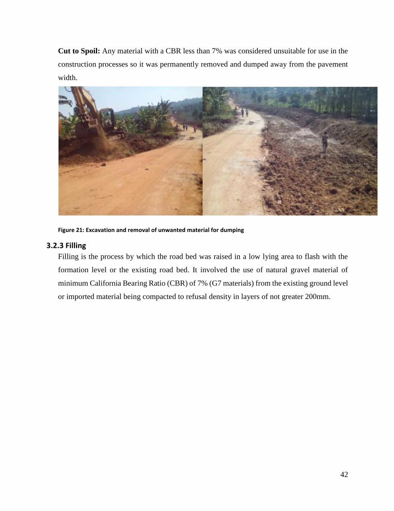
42
Cut to Spoil: Any material with a CBR less than 7% was considered unsuitable for use in the
construction processes so it was permanently removed and dumped away from the pavement
width.
Figure 21: Excavation and removal of unwanted material for dumping
3.2.3 Filling
Filling is the process by which the road bed was raised in a low lying area to flash with the
formation level or the existing road bed. It involved the use of natural gravel material of
minimum California Bearing Ratio (CBR) of 7% (G7 materials) from the existing ground level
or imported material being compacted to refusal density in layers of not greater 200mm.
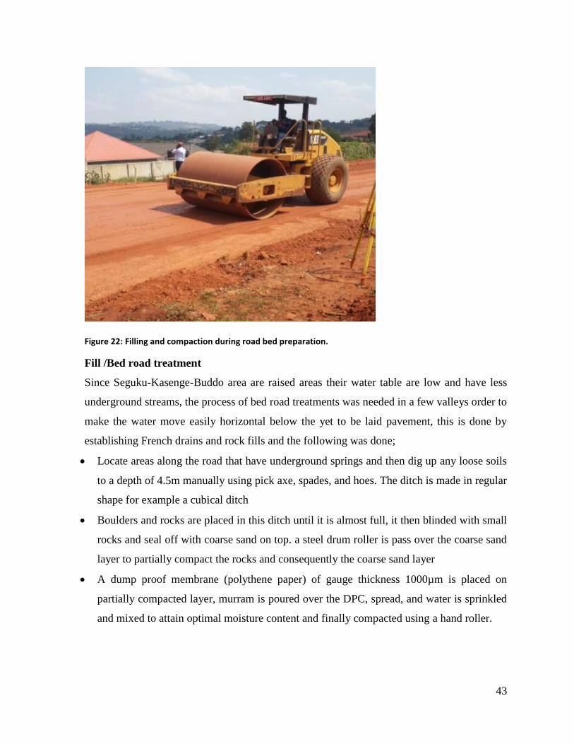
43
Figure 22: Filling and compaction during road bed preparation.
Fill /Bed road treatment
Since Seguku-Kasenge-Buddo area are raised areas their water table are low and have less
underground streams, the process of bed road treatments was needed in a few valleys order to
make the water move easily horizontal below the yet to be laid pavement, this is done by
establishing French drains and rock fills and the following was done;
Locate areas along the road that have underground springs and then dig up any loose soils
to a depth of 4.5m manually using pick axe, spades, and hoes. The ditch is made in regular
shape for example a cubical ditch
Boulders and rocks are placed in this ditch until it is almost full, it then blinded with small
rocks and seal off with coarse sand on top. a steel drum roller is pass over the coarse sand
layer to partially compact the rocks and consequently the coarse sand layer
A dump proof membrane (polythene paper) of gauge thickness 1000µm is placed on
partially compacted layer, murram is poured over the DPC, spread, and water is sprinkled
and mixed to attain optimal moisture content and finally compacted using a hand roller.
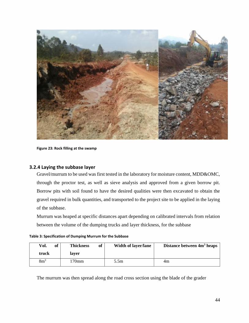
44
Figure 23: Rock filling at the swamp
3.2.4 Laying the subbase layer
Gravel/murrum to be used was first tested in the laboratory for moisture content, MDD&OMC,
through the proctor test, as well as sieve analysis and approved from a given borrow pit.
Borrow pits with soil found to have the desired qualities were then excavated to obtain the
gravel required in bulk quantities, and transported to the project site to be applied in the laying
of the subbase.
Murrum was heaped at specific distances apart depending on calibrated intervals from relation
between the volume of the dumping trucks and layer thickness, for the subbase
Table 3: Specification of Dumping Murrum for the Subbase
Vol. of
truck
Thickness of
layer
Width of layer/lane Distance between 4m3 heaps
8m3 170mm 5.5m 4m
The murrum was then spread along the road cross section using the blade of the grader
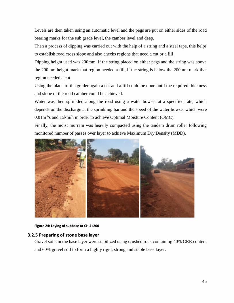
45
Levels are then taken using an automatic level and the pegs are put on either sides of the road
bearing marks for the sub grade level, the camber level and deep.
Then a process of dipping was carried out with the help of a string and a steel tape, this helps
to establish road cross slope and also checks regions that need a cut or a fill
Dipping height used was 200mm. If the string placed on either pegs and the string was above
the 200mm height mark that region needed a fill, if the string is below the 200mm mark that
region needed a cut
Using the blade of the grader again a cut and a fill could be done until the required thickness
and slope of the road camber could be achieved.
Water was then sprinkled along the road using a water bowser at a specified rate, which
depends on the discharge at the sprinkling bar and the speed of the water bowser which were
0.01m3/s and 15km/h in order to achieve Optimal Moisture Content (OMC).
Finally, the moist murram was heavily compacted using the tandem drum roller following
monitored number of passes over layer to achieve Maximum Dry Density (MDD).
Figure 24: Laying of subbase at CH 4+200
3.2.5 Preparing of stone base layer
Gravel soils in the base layer were stabilized using crushed rock containing 40% CRR content
and 60% gravel soil to form a highly rigid, strong and stable base layer.
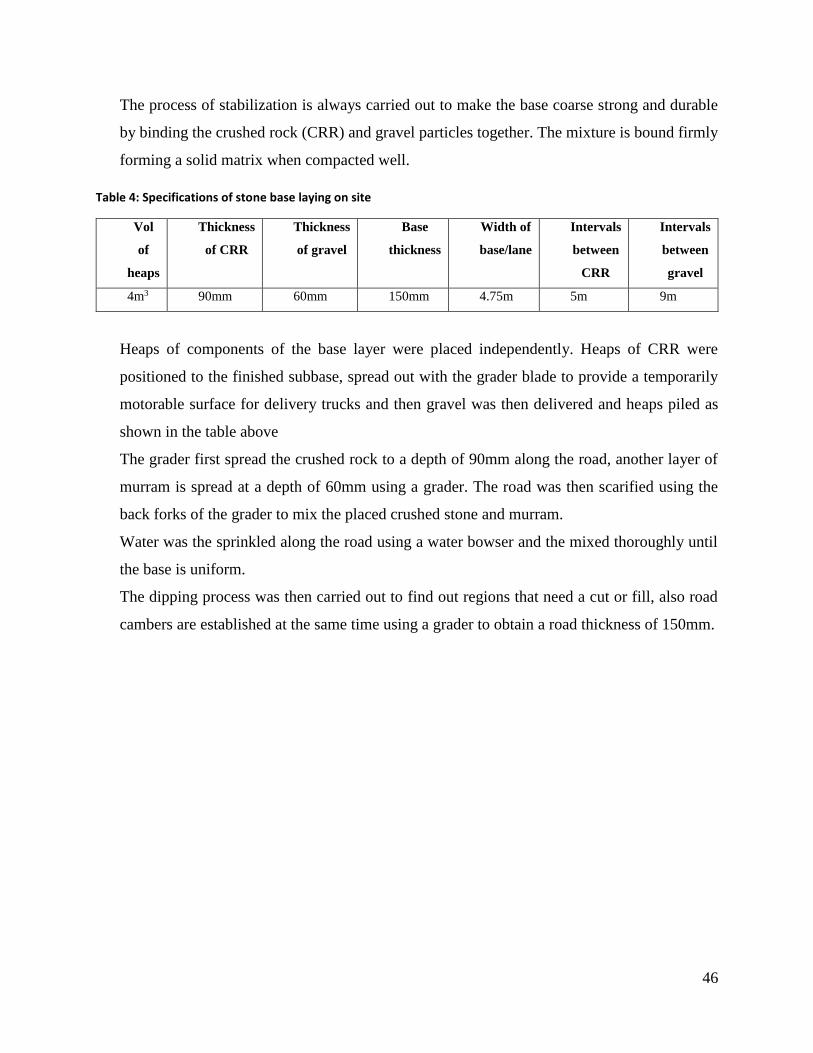
46
The process of stabilization is always carried out to make the base coarse strong and durable
by binding the crushed rock (CRR) and gravel particles together. The mixture is bound firmly
forming a solid matrix when compacted well.
Table 4: Specifications of stone base laying on site
Vol
of
heaps
Thickness
of CRR
Thickness
of gravel
Base
thickness
Width of
base/lane
Intervals
between
CRR
Intervals
between
gravel
4m3 90mm 60mm 150mm 4.75m 5m 9m
Heaps of components of the base layer were placed independently. Heaps of CRR were
positioned to the finished subbase, spread out with the grader blade to provide a temporarily
motorable surface for delivery trucks and then gravel was then delivered and heaps piled as
shown in the table above
The grader first spread the crushed rock to a depth of 90mm along the road, another layer of
murram is spread at a depth of 60mm using a grader. The road was then scarified using the
back forks of the grader to mix the placed crushed stone and murram.
Water was the sprinkled along the road using a water bowser and the mixed thoroughly until
the base is uniform.
The dipping process was then carried out to find out regions that need a cut or fill, also road
cambers are established at the same time using a grader to obtain a road thickness of 150mm.
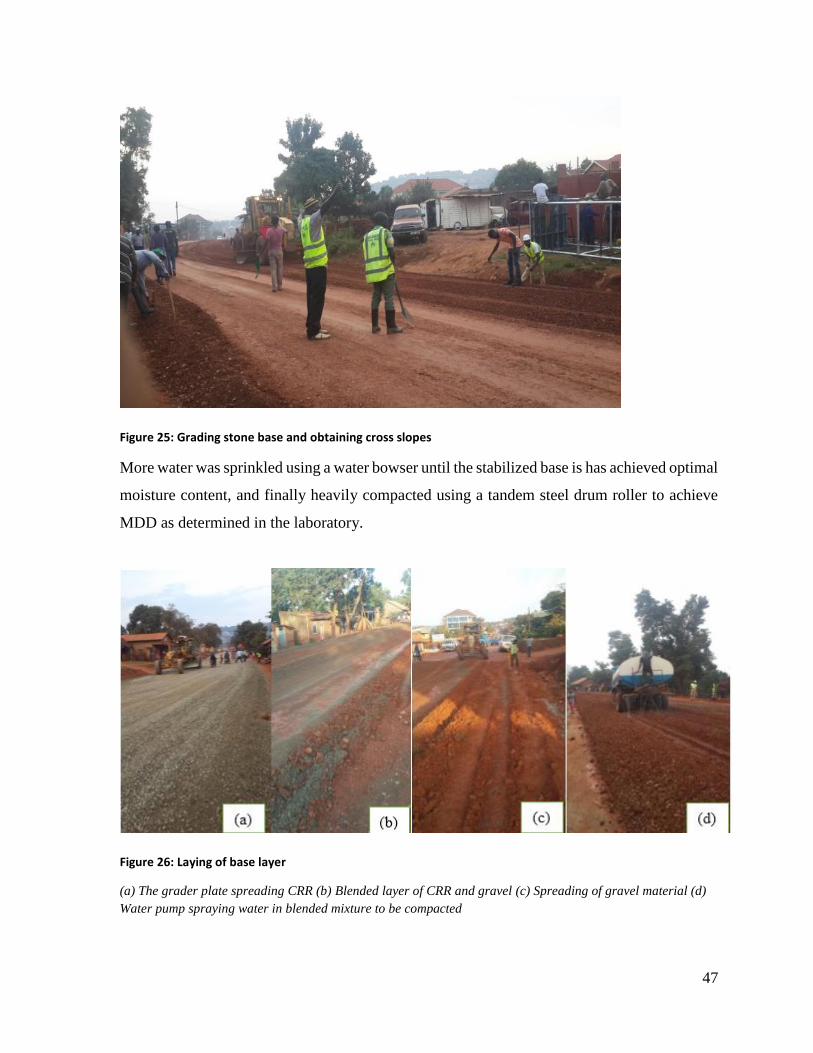
47
Figure 25: Grading stone base and obtaining cross slopes
More water was sprinkled using a water bowser until the stabilized base is has achieved optimal
moisture content, and finally heavily compacted using a tandem steel drum roller to achieve
MDD as determined in the laboratory.
Figure 26: Laying of base layer
(a) The grader plate spreading CRR (b) Blended layer of CRR and gravel (c) Spreading of gravel material (d)
Water pump spraying water in blended mixture to be compacted
48
3.2.6 Checking depth of constructed pavement layers
The depth of constructed pavement layers was checked manually along 100m intervals by a
shallow excavation/ coring process where a section along the road length was cored using a
pick axe, making an excavation of 𝐷𝑖𝑎𝑚𝑒𝑡𝑒𝑟 ≈ 50𝑚𝑚
The hole was dug to a 𝐷𝑒𝑝𝑡ℎ ≥ 350𝑚𝑚 and with the help of a steel tape, the depth of each
layer was observed and noted, as a validation check to determine whether the depth of each
layer conforms to the standards
3.3 Insitu Geotechnical tests
3.3.1 Dynamic Cone Penetrometer test (DCP)
The DCP test was carried out on Insitu soils to establish the strength of the existing subgrade,
and its ability to support traffic loads without risk of failing under bearing capacity or
settlement
Objective
To determine the mechanical properties of existing pavement layers for use in structural
pavement design and to provide a measure of a material’s insitu resistance to penetration.
Principle
The underlying principle of the DCP is that the rate of penetration of the cone, when driven by
a standard force, is inversely proportional to the strength of the material for example in the
CBR test. Where the pavement layers have different strengths, the boundaries between the
layers can be identified and the thickness of the layers determined
Reference
BS 5930:1999
Equipment
DCP machine
Bottom rod, top rod (hammer shaft), falling hammer (8kgs falling through 575mm), meter rule,
60° cone.
Refer to figure 3.20 for DCP apparatus.
Road safety wear and equipment for traffic control
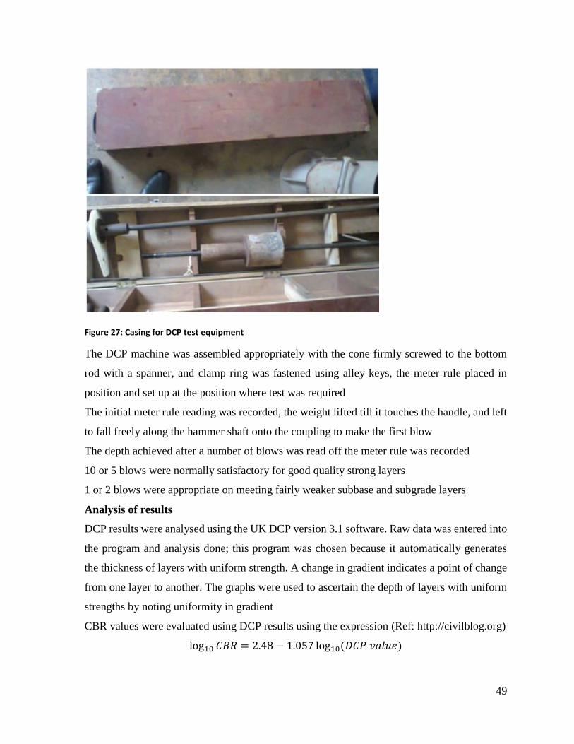
49
Figure 27: Casing for DCP test equipment
The DCP machine was assembled appropriately with the cone firmly screwed to the bottom
rod with a spanner, and clamp ring was fastened using alley keys, the meter rule placed in
position and set up at the position where test was required
The initial meter rule reading was recorded, the weight lifted till it touches the handle, and left
to fall freely along the hammer shaft onto the coupling to make the first blow
The depth achieved after a number of blows was read off the meter rule was recorded
10 or 5 blows were normally satisfactory for good quality strong layers
1 or 2 blows were appropriate on meeting fairly weaker subbase and subgrade layers
Analysis of results
DCP results were analysed using the UK DCP version 3.1 software. Raw data was entered into
the program and analysis done; this program was chosen because it automatically generates
the thickness of layers with uniform strength. A change in gradient indicates a point of change
from one layer to another. The graphs were used to ascertain the depth of layers with uniform
strengths by noting uniformity in gradient
CBR values were evaluated using DCP results using the expression (Ref: http://civilblog.org)
log10 𝐶𝐵𝑅 = 2.48 − 1.057 log10(𝐷𝐶𝑃 𝑣𝑎𝑙𝑢𝑒)
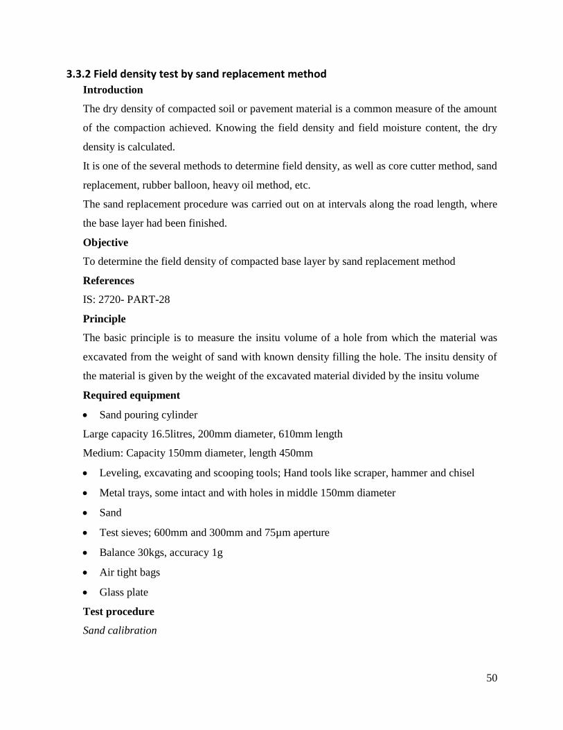
50
3.3.2 Field density test by sand replacement method
Introduction
The dry density of compacted soil or pavement material is a common measure of the amount
of the compaction achieved. Knowing the field density and field moisture content, the dry
density is calculated.
It is one of the several methods to determine field density, as well as core cutter method, sand
replacement, rubber balloon, heavy oil method, etc.
The sand replacement procedure was carried out on at intervals along the road length, where
the base layer had been finished.
Objective
To determine the field density of compacted base layer by sand replacement method
References
IS: 2720- PART-28
Principle
The basic principle is to measure the insitu volume of a hole from which the material was
excavated from the weight of sand with known density filling the hole. The insitu density of
the material is given by the weight of the excavated material divided by the insitu volume
Required equipment
Sand pouring cylinder
Large capacity 16.5litres, 200mm diameter, 610mm length
Medium: Capacity 150mm diameter, length 450mm
Leveling, excavating and scooping tools; Hand tools like scraper, hammer and chisel
Metal trays, some intact and with holes in middle 150mm diameter
Sand
Test sieves; 600mm and 300mm and 75µm aperture
Balance 30kgs, accuracy 1g
Air tight bags
Glass plate
Test procedure
Sand calibration
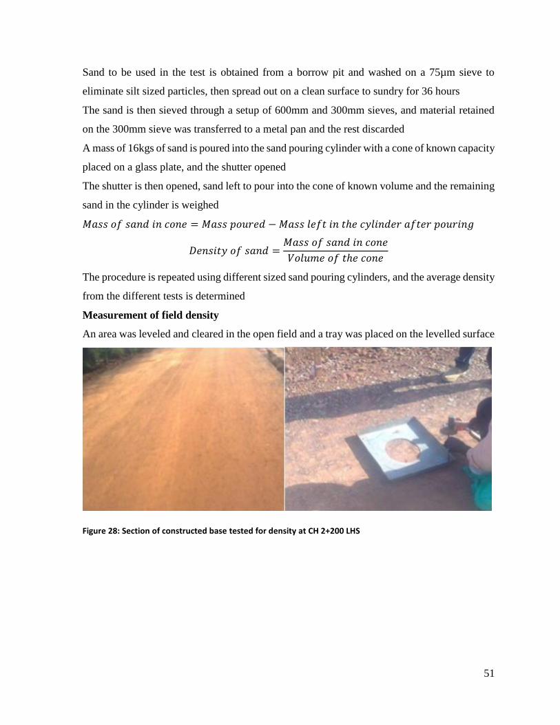
51
Sand to be used in the test is obtained from a borrow pit and washed on a 75µm sieve to
eliminate silt sized particles, then spread out on a clean surface to sundry for 36 hours
The sand is then sieved through a setup of 600mm and 300mm sieves, and material retained
on the 300mm sieve was transferred to a metal pan and the rest discarded
A mass of 16kgs of sand is poured into the sand pouring cylinder with a cone of known capacity
placed on a glass plate, and the shutter opened
The shutter is then opened, sand left to pour into the cone of known volume and the remaining
sand in the cylinder is weighed
𝑀𝑎𝑠𝑠 𝑜𝑓 𝑠𝑎𝑛𝑑 𝑖𝑛 𝑐𝑜𝑛𝑒 = 𝑀𝑎𝑠𝑠 𝑝𝑜𝑢𝑟𝑒𝑑 − 𝑀𝑎𝑠𝑠 𝑙𝑒𝑓𝑡 𝑖𝑛 𝑡ℎ𝑒 𝑐𝑦𝑙𝑖𝑛𝑑𝑒𝑟 𝑎𝑓𝑡𝑒𝑟 𝑝𝑜𝑢𝑟𝑖𝑛𝑔
𝐷𝑒𝑛𝑠𝑖𝑡𝑦 𝑜𝑓 𝑠𝑎𝑛𝑑 =𝑀𝑎𝑠𝑠 𝑜𝑓 𝑠𝑎𝑛𝑑 𝑖𝑛 𝑐𝑜𝑛𝑒
𝑉𝑜𝑙𝑢𝑚𝑒 𝑜𝑓 𝑡ℎ𝑒 𝑐𝑜𝑛𝑒
The procedure is repeated using different sized sand pouring cylinders, and the average density
from the different tests is determined
Measurement of field density
An area was leveled and cleared in the open field and a tray was placed on the levelled surface
Figure 28: Section of constructed base tested for density at CH 2+200 LHS
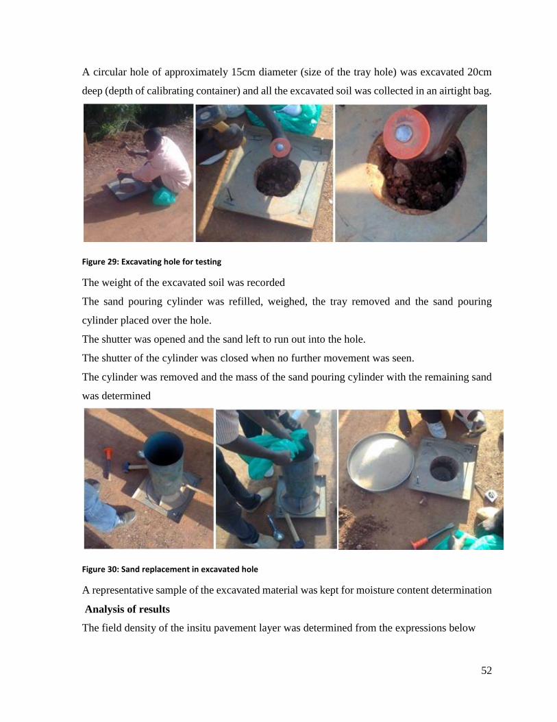
52
A circular hole of approximately 15cm diameter (size of the tray hole) was excavated 20cm
deep (depth of calibrating container) and all the excavated soil was collected in an airtight bag.
Figure 29: Excavating hole for testing
The weight of the excavated soil was recorded
The sand pouring cylinder was refilled, weighed, the tray removed and the sand pouring
cylinder placed over the hole.
The shutter was opened and the sand left to run out into the hole.
The shutter of the cylinder was closed when no further movement was seen.
The cylinder was removed and the mass of the sand pouring cylinder with the remaining sand
was determined
Figure 30: Sand replacement in excavated hole
A representative sample of the excavated material was kept for moisture content determination
Analysis of results
The field density of the insitu pavement layer was determined from the expressions below
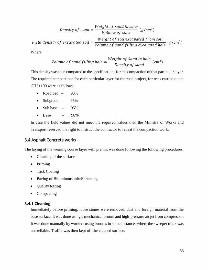
53
𝐷𝑒𝑛𝑠𝑖𝑡𝑦 𝑜𝑓 𝑠𝑎𝑛𝑑 =𝑊𝑒𝑖𝑔ℎ𝑡 𝑜𝑓 𝑠𝑎𝑛𝑑 𝑖𝑛 𝑐𝑜𝑛𝑒
𝑉𝑜𝑙𝑢𝑚𝑒 𝑜𝑓 𝑐𝑜𝑛𝑒 (𝑔/𝑐𝑚3)
𝐹𝑖𝑒𝑙𝑑 𝑑𝑒𝑛𝑠𝑖𝑡𝑦 𝑜𝑓 𝑒𝑥𝑐𝑎𝑣𝑎𝑡𝑒𝑑 𝑠𝑜𝑖𝑙 =𝑊𝑒𝑖𝑔ℎ𝑡 𝑜𝑓 𝑠𝑜𝑖𝑙 𝑒𝑥𝑐𝑎𝑣𝑎𝑡𝑒𝑑 𝑓𝑟𝑜𝑚 𝑠𝑜𝑖𝑙
𝑉𝑜𝑙𝑢𝑚𝑒 𝑜𝑓 𝑠𝑎𝑛𝑑 𝑓𝑖𝑙𝑙𝑖𝑛𝑔 𝑒𝑥𝑐𝑎𝑣𝑎𝑡𝑒𝑑 ℎ𝑜𝑙𝑒 (𝑔/𝑐𝑚3)
Where
𝑉𝑜𝑙𝑢𝑚𝑒 𝑜𝑓 𝑠𝑎𝑛𝑑 𝑓𝑖𝑙𝑙𝑖𝑛𝑔 ℎ𝑜𝑙𝑒 =𝑊𝑒𝑖𝑔ℎ𝑡 𝑜𝑓 𝑆𝑎𝑛𝑑 𝑖𝑛 ℎ𝑜𝑙𝑒
𝐷𝑒𝑛𝑠𝑖𝑡𝑦 𝑜𝑓 𝑠𝑎𝑛𝑑 (𝑐𝑚3)
This density was then compared to the specifications for the compaction of that particular layer.
The required compactions for each particular layer for the road project, for tests carried out at
CH2+100 were as follows:
Road bed – 93%
Subgrade – 95%
Sub base – 95%
Base – 98%
In case the field values did not meet the required values then the Ministry of Works and
Transport reserved the right to instruct the contractor to repeat the compaction work.
3.4 Asphalt Concrete works
The laying of the wearing course layer with premix was done following the following procedures:
Cleaning of the surface
Priming
Tack Coating
Paving of Bituminous mix/Spreading
Quality testing
Compacting
3.4.1 Cleaning
Immediately before priming, loose stones were removed, dust and foreign material from the
base surface. It was done using a mechanical broom and high-pressure air jet from compressor.
It was done manually by workers using brooms in some instances where the sweeper truck was
not reliable. Traffic was then kept off the cleaned surface.
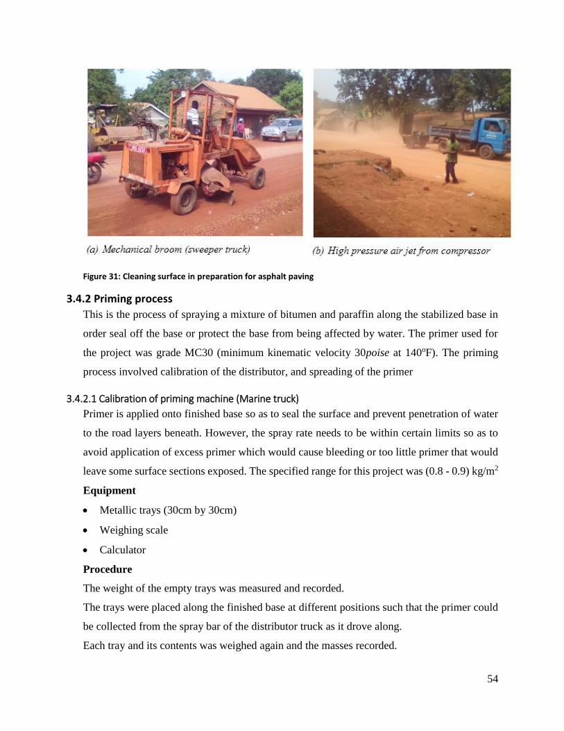
54
Figure 31: Cleaning surface in preparation for asphalt paving
3.4.2 Priming process
This is the process of spraying a mixture of bitumen and paraffin along the stabilized base in
order seal off the base or protect the base from being affected by water. The primer used for
the project was grade MC30 (minimum kinematic velocity 30poise at 140oF). The priming
process involved calibration of the distributor, and spreading of the primer
3.4.2.1 Calibration of priming machine (Marine truck)
Primer is applied onto finished base so as to seal the surface and prevent penetration of water
to the road layers beneath. However, the spray rate needs to be within certain limits so as to
avoid application of excess primer which would cause bleeding or too little primer that would
leave some surface sections exposed. The specified range for this project was (0.8 - 0.9) kg/m2
Equipment
Metallic trays (30cm by 30cm)
Weighing scale
Calculator
Procedure
The weight of the empty trays was measured and recorded.
The trays were placed along the finished base at different positions such that the primer could
be collected from the spray bar of the distributor truck as it drove along.
Each tray and its contents was weighed again and the masses recorded.

55
Figure 32: Calibrating primer distributor truck
The trays were used to monitor the priming process for a specified section of the road from
CH 0+300 to CH 0+700 to ensure the average spray rate of the distributor truck was within the
specified range to achieve the required primer thickness
The spray rate was determined as follows using one of the test trays:
𝐴𝑟𝑒𝑎 𝑜𝑓 𝑡𝑟𝑎𝑦 = 0.3 × 0.3 = 0.09𝑚2
𝑊𝑒𝑖𝑔ℎ𝑡 𝑜𝑓 𝑒𝑚𝑝𝑡𝑦 𝑡𝑟𝑎𝑦 = 1.960𝑘𝑔
𝑊𝑒𝑖𝑔ℎ𝑡 𝑜𝑓 𝑡𝑟𝑎𝑦 𝑤𝑖𝑡ℎ 𝑝𝑟𝑖𝑚𝑒𝑟 = 2.035𝑘𝑔
𝑊𝑒𝑖𝑔ℎ𝑡 𝑜𝑓 𝑝𝑟𝑖𝑚𝑒𝑟 = 2.035 − 1.960 = 0.075𝑘𝑔
𝑆𝑝𝑟𝑎𝑦 𝑟𝑎𝑡𝑒 =𝑊𝑒𝑖𝑔ℎ𝑡 𝑜𝑓 𝑝𝑟𝑖𝑚𝑒𝑟 𝑐𝑜𝑙𝑙𝑒𝑐𝑡𝑒𝑑
𝐴𝑟𝑒𝑎 𝑜𝑓 𝑡𝑟𝑎𝑦=
0.075
0.09= 0.833𝑘𝑔/𝑚2
The spray rate obtained in this trial was within acceptable range. In case the spray rate was out
of range, the driver would be directed by the technician to either increase or reduce speed of
the distributor accordingly.
3.4.2.2 Spreading the primer
With the surface blocked off from traffic, the clean stabilized base was sprinkled with some
water, at a faster rate to prevent any dust residual particles from interrupting the priming
process
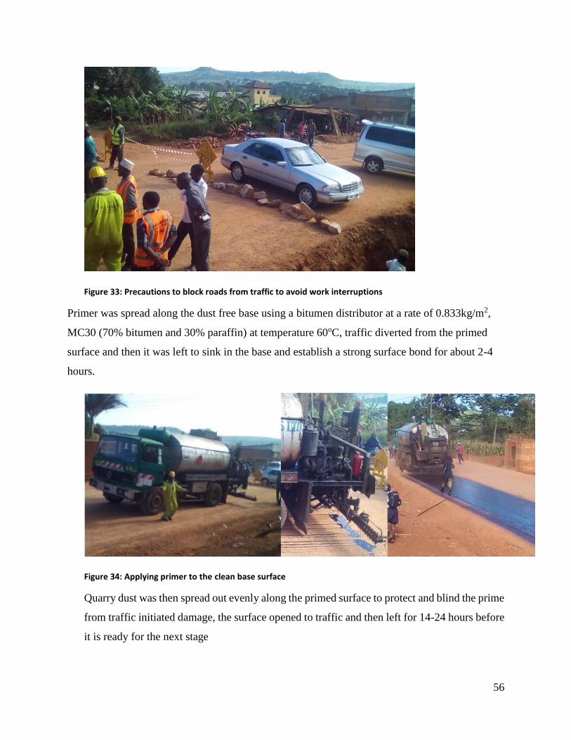
56
Figure 33: Precautions to block roads from traffic to avoid work interruptions
Primer was spread along the dust free base using a bitumen distributor at a rate of 0.833kg/m2,
MC30 (70% bitumen and 30% paraffin) at temperature 60oC, traffic diverted from the primed
surface and then it was left to sink in the base and establish a strong surface bond for about 2-4
hours.
Figure 34: Applying primer to the clean base surface
Quarry dust was then spread out evenly along the primed surface to protect and blind the prime
from traffic initiated damage, the surface opened to traffic and then left for 14-24 hours before
it is ready for the next stage
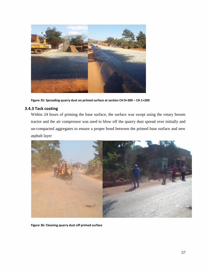
57
Figure 35: Spreading quarry dust on primed surface at section CH 0+300 – CH 1+200
3.4.3 Tack coating
Within 24 hours of priming the base surface, the surface was swept using the rotary broom
tractor and the air compressor was used to blow off the quarry dust spread over initially and
un-compacted aggregates to ensure a proper bond between the primed base surface and new
asphalt layer
Figure 36: Cleaning quarry dust off primed surface
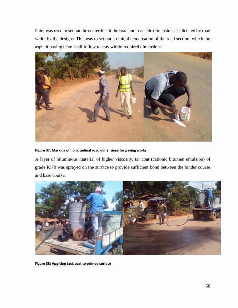
58
Paint was used to set out the centerline of the road and roadside dimensions as dictated by road
width by the designs. This was to set out an initial demarcation of the road section, which the
asphalt paving team shall follow to stay within required dimensions
Figure 37: Marking off longitudinal road dimensions for paving works
A layer of bituminous material of higher viscosity, tar coat (cationic bitumen emulsion) of
grade Ki70 was sprayed on the surface to provide sufficient bond between the binder course
and base course.
Figure 38: Applying tack coat to primed surface
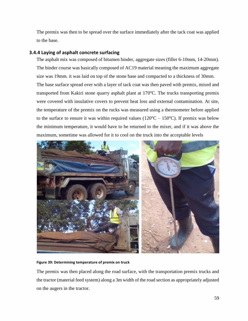
59
The premix was then to be spread over the surface immediately after the tack coat was applied
to the base.
3.4.4 Laying of asphalt concrete surfacing
The asphalt mix was composed of bitumen binder, aggregate sizes (filler 6-10mm, 14-20mm).
The binder course was basically composed of AC19 material meaning the maximum aggregate
size was 19mm. it was laid on top of the stone base and compacted to a thickness of 30mm.
The base surface spread over with a layer of tack coat was then paved with premix, mixed and
transported from Kakiri stone quarry asphalt plant at 170oC. The trucks transporting premix
were covered with insulative covers to prevent heat loss and external contamination. At site,
the temperature of the premix on the rucks was measured using a thermometer before applied
to the surface to ensure it was within required values (120oC – 150oC). If premix was below
the minimum temperature, it would have to be returned to the mixer, and if it was above the
maximum, sometime was allowed for it to cool on the truck into the acceptable levels
Figure 39: Determining temperature of premix on truck
The premix was then placed along the road surface, with the transportation premix trucks and
the tractor (material feed system) along a 3m width of the road section as appropriately adjusted
on the augers in the tractor.
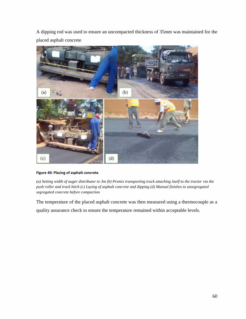
60
A dipping rod was used to ensure an uncompacted thickness of 35mm was maintained for the
placed asphalt concrete
Figure 40: Placing of asphalt concrete
(a) Setting width of auger distributor to 3m (b) Premix transporting truck attaching itself to the tractor via the
push roller and truck hitch (c) Laying of asphalt concrete and dipping (d) Manual finishes to unsegregated
segregated concrete before compaction
The temperature of the placed asphalt concrete was then measured using a thermocouple as a
quality assurance check to ensure the temperature remained within acceptable levels.
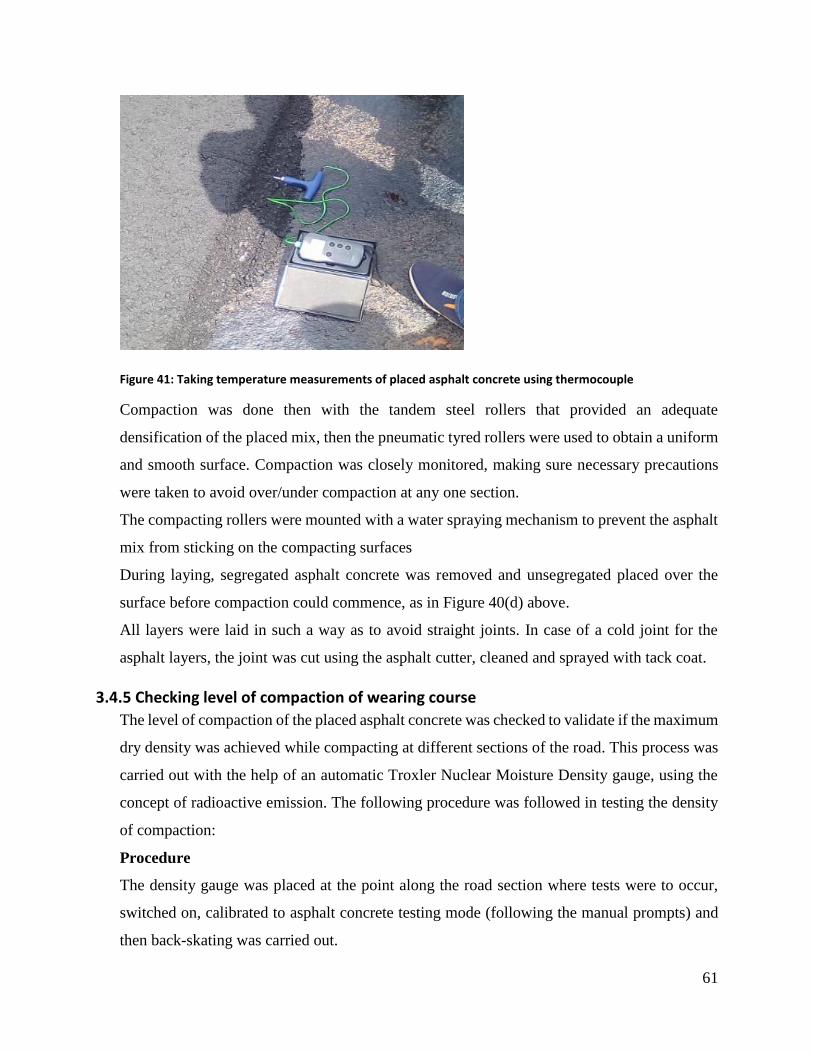
61
Figure 41: Taking temperature measurements of placed asphalt concrete using thermocouple
Compaction was done then with the tandem steel rollers that provided an adequate
densification of the placed mix, then the pneumatic tyred rollers were used to obtain a uniform
and smooth surface. Compaction was closely monitored, making sure necessary precautions
were taken to avoid over/under compaction at any one section.
The compacting rollers were mounted with a water spraying mechanism to prevent the asphalt
mix from sticking on the compacting surfaces
During laying, segregated asphalt concrete was removed and unsegregated placed over the
surface before compaction could commence, as in Figure 40(d) above.
All layers were laid in such a way as to avoid straight joints. In case of a cold joint for the
asphalt layers, the joint was cut using the asphalt cutter, cleaned and sprayed with tack coat.
3.4.5 Checking level of compaction of wearing course
The level of compaction of the placed asphalt concrete was checked to validate if the maximum
dry density was achieved while compacting at different sections of the road. This process was
carried out with the help of an automatic Troxler Nuclear Moisture Density gauge, using the
concept of radioactive emission. The following procedure was followed in testing the density
of compaction:
Procedure
The density gauge was placed at the point along the road section where tests were to occur,
switched on, calibrated to asphalt concrete testing mode (following the manual prompts) and
then back-skating was carried out.
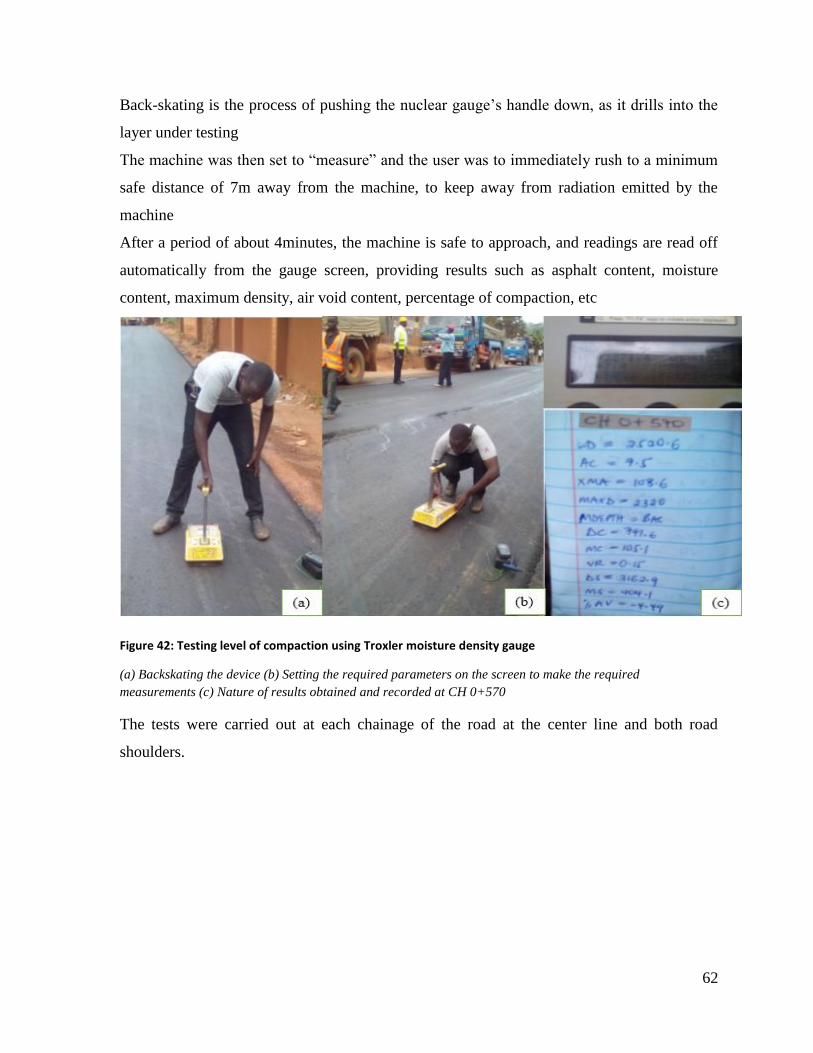
62
Back-skating is the process of pushing the nuclear gauge’s handle down, as it drills into the
layer under testing
The machine was then set to “measure” and the user was to immediately rush to a minimum
safe distance of 7m away from the machine, to keep away from radiation emitted by the
machine
After a period of about 4minutes, the machine is safe to approach, and readings are read off
automatically from the gauge screen, providing results such as asphalt content, moisture
content, maximum density, air void content, percentage of compaction, etc
Figure 42: Testing level of compaction using Troxler moisture density gauge
(a) Backskating the device (b) Setting the required parameters on the screen to make the required
measurements (c) Nature of results obtained and recorded at CH 0+570
The tests were carried out at each chainage of the road at the center line and both road
shoulders.

63
Table 5: The average results obtained CH 0+300 to CH 0+500.
Parameters Results from
the troxler
Required results
1.from the LAB
Conclusion
Moisture content
(MC)
14.56% 13.1% Passed
Dry Density
(DD)/kgm-3
1994.11 1870 Passed
Wet Density
(WD)/kgm-3
2281.73 2260 Passed
Proctor Ratio
(PR)
108.25% 95% Passed
3.5 DRAINAGE
3.5.1 Introduction
The functional life of a pavement is greatly reduced if storm runoff is not drained off the
surface and from the vicinity of the pavement. Surface water can enter the pavement through
the porous surface, at the end of the carriageway and through cracks that develop as the
pavement ages. This can lead to weakening of the pavement structure resulting into severe road
defects such as potholes. Capillary rise of ground water from beneath the pavement can lead
to saturation of the pavement structure causing further weakening of the pavement.
It is therefore imperative that proper drainage features are provided and installed at points of
need. The drainage features that were provided for on the road include; cumber (cross slope),
side slopes, road side ditches, culverts and drainage beds.
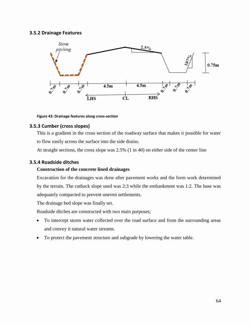
64
3.5.2 Drainage Features
Figure 43: Drainage features along cross-section
3.5.3 Cumber (cross slopes)
This is a gradient in the cross section of the roadway surface that makes it possible for water
to flow easily across the surface into the side drains.
At straight sections, the cross slope was 2.5% (1 in 40) on either side of the center line
3.5.4 Roadside ditches
Construction of the concrete lined drainages
Excavation for the drainages was done after pavement works and the form work determined
by the terrain. The cutback slope used was 2:3 while the embankment was 1:2. The base was
adequately compacted to prevent uneven settlements.
The drainage bed slope was finally set.
Roadside ditches are constructed with two main purposes;
To intercept storm water collected over the road surface and from the surrounding areas
and convey it natural water streams.
To protect the pavement structure and subgrade by lowering the water table.
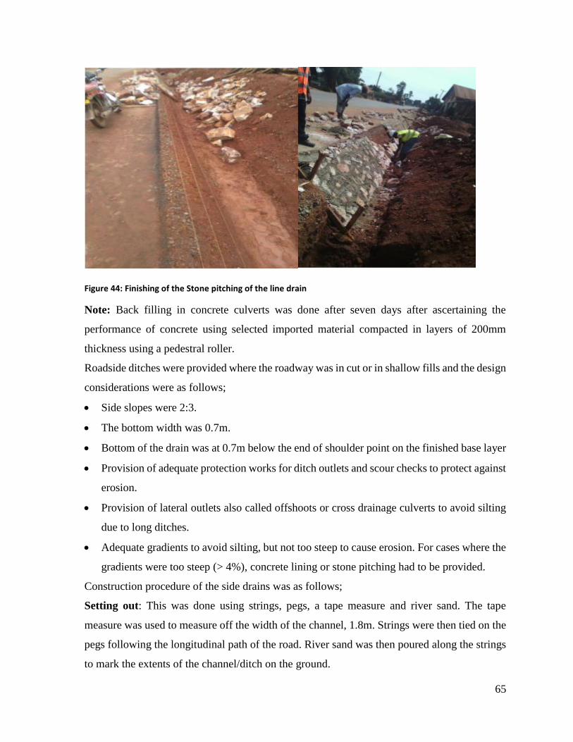
65
Figure 44: Finishing of the Stone pitching of the line drain
Note: Back filling in concrete culverts was done after seven days after ascertaining the
performance of concrete using selected imported material compacted in layers of 200mm
thickness using a pedestral roller.
Roadside ditches were provided where the roadway was in cut or in shallow fills and the design
considerations were as follows;
Side slopes were 2:3.
The bottom width was 0.7m.
Bottom of the drain was at 0.7m below the end of shoulder point on the finished base layer
Provision of adequate protection works for ditch outlets and scour checks to protect against
erosion.
Provision of lateral outlets also called offshoots or cross drainage culverts to avoid silting
due to long ditches.
Adequate gradients to avoid silting, but not too steep to cause erosion. For cases where the
gradients were too steep (> 4%), concrete lining or stone pitching had to be provided.
Construction procedure of the side drains was as follows;
Setting out: This was done using strings, pegs, a tape measure and river sand. The tape
measure was used to measure off the width of the channel, 1.8m. Strings were then tied on the
pegs following the longitudinal path of the road. River sand was then poured along the strings
to mark the extents of the channel/ditch on the ground.
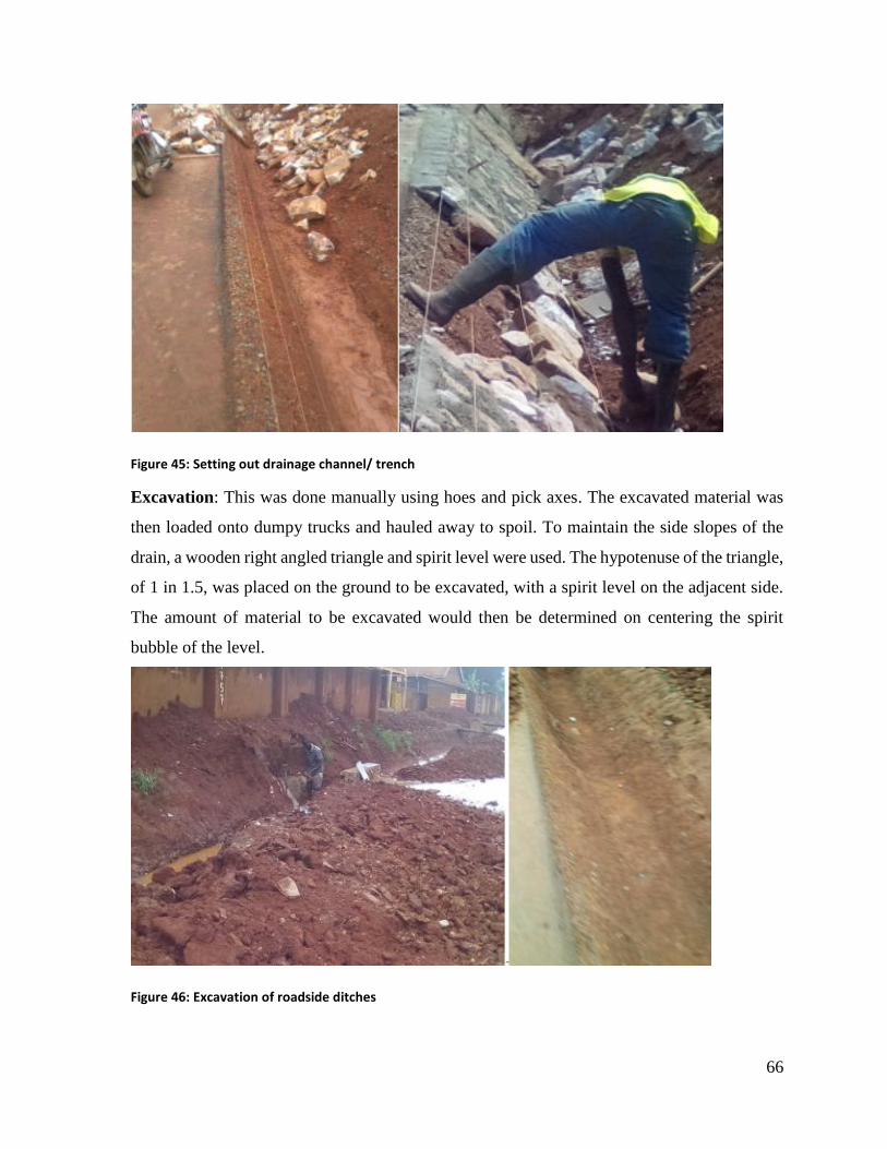
66
Figure 45: Setting out drainage channel/ trench
Excavation: This was done manually using hoes and pick axes. The excavated material was
then loaded onto dumpy trucks and hauled away to spoil. To maintain the side slopes of the
drain, a wooden right angled triangle and spirit level were used. The hypotenuse of the triangle,
of 1 in 1.5, was placed on the ground to be excavated, with a spirit level on the adjacent side.
The amount of material to be excavated would then be determined on centering the spirit
bubble of the level.
Figure 46: Excavation of roadside ditches
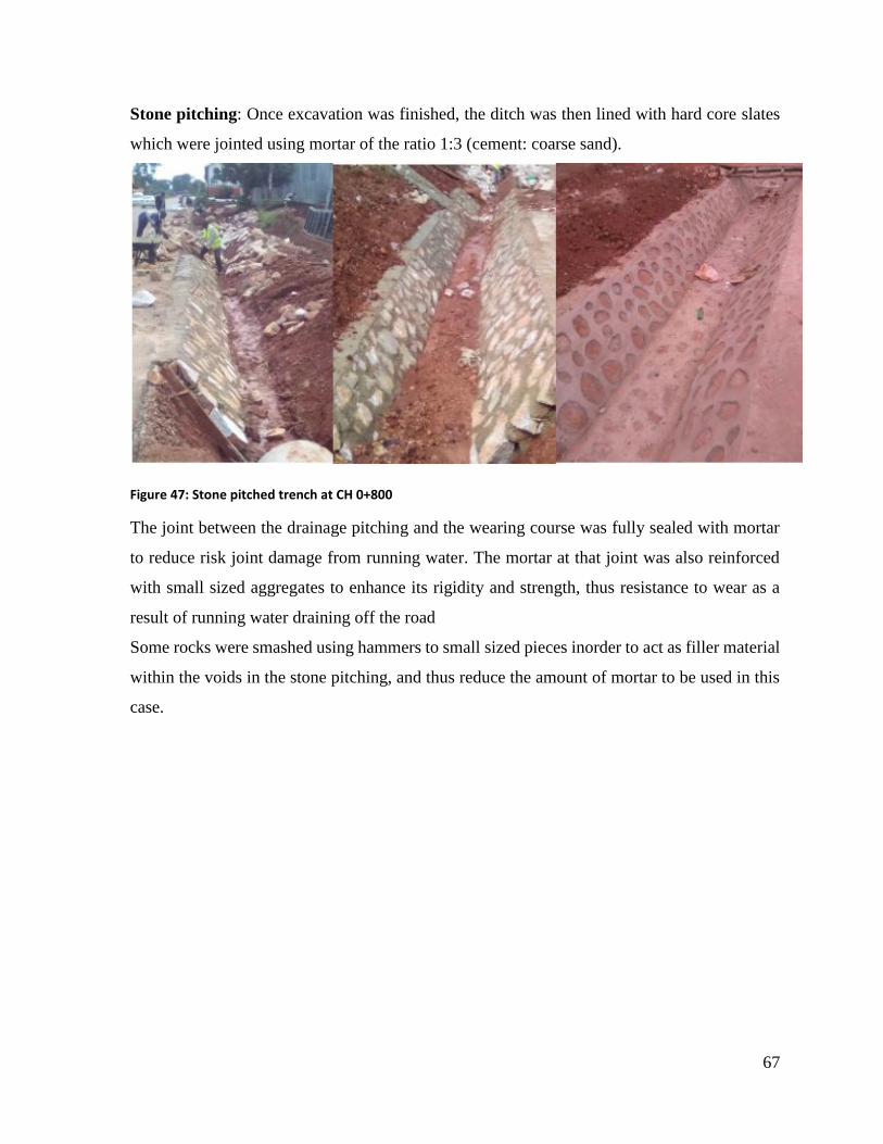
67
Stone pitching: Once excavation was finished, the ditch was then lined with hard core slates
which were jointed using mortar of the ratio 1:3 (cement: coarse sand).
Figure 47: Stone pitched trench at CH 0+800
The joint between the drainage pitching and the wearing course was fully sealed with mortar
to reduce risk joint damage from running water. The mortar at that joint was also reinforced
with small sized aggregates to enhance its rigidity and strength, thus resistance to wear as a
result of running water draining off the road
Some rocks were smashed using hammers to small sized pieces inorder to act as filler material
within the voids in the stone pitching, and thus reduce the amount of mortar to be used in this
case.
68
CHAPTER FOUR: OBSERVATIONS, CONCLUSIONS AND
RECOMMENDATIONS During my industrial training period that took place from 6th/June to 29th/July on the Seguku-
Kasenge-Buddo construction project, there were a number of things I achieved working with
the various people I got to associate with. Also, there were a couple of challenges, both
inevitable and modifiable that were faced during the activities proceeding on site
This chapter describes the personal achievements I obtained during my time spent in the
industrial training and some of the major challenges I observed and a personal opinion of what
could be done to overcome some of the issues I noticed during my time there.
The challenges have been categorically organized according to the concerned stakeholder, i.e;
by me as the intern and the contractor (Abubaker Technical Services and General Supplies
Ltd)
4.1 Achievements from the industrial training
I was exposed to several practical aspects of engineering and construction activities
I got an opportunity to relate the knowledge obtained during lectures to actual field
operations
I created an understanding of the roles played by the different project personnel during
project execution
It enabled me to learn how to work in a team with the different team players (casual
workers, technicians, engineers, etc.)
I was able to learn different engineering ethics necessary for career building
I was able to enhance my problem solving capacity using available appropriate technology
and the surrounding condition
The internship training enabled me to have a hands-on with tools and equipment not readily
available in the University laboratories and are of great importance in the engineering field
The industrial training experience enabled me appreciate the various challenges faced in
the field and some critical areas necessitating further research studies.
69
4.2 Challenges faced and suggested solutions;
4.2.1 By the internship trainee
There was a challenge of a large number of interns present at the site for training, relative to
the present trainers (technical workers). This, to a certain extent made planning and supervisory
action quite cumbersome to the contractors, and the learning process was quite slow due to the
hardship involved in teaching a large number of students
I would suggest that the establishment of an internship placement allocation system,
planned such that a maximum number of students to enroll at a specific site is determined
and implemented.
High costs involved; I incurred large non pocket friendly costs on transport. This was
predominantly due to the large distance from my residence to the work place. This made the
working conditions quite challenging at times. Abubaker contracting company however
provided meals for interns at the site, which cut down on the feeding costs
I would like to suggest that the internship trainers develop a form of incentives or
allowances dedicated to cater for some costs incurred by trainees in order to lessen on the
financial burden faced by the trainees
Alternatively, the trainers could setup a sort of camp neighboring the site to accommodate
trainees in order to cut down on costs they incur in terms of transport
Absence of an organized training program for the trainees; Trainees were not subjected to or
set up with a systematized form of training program to follow, which resulted into occasional
muddle among intern students and at times absenteeism. This was most especially during
periods when works were minimal on site.
The training team should often develop a systematic program for the trainees to follow,
inorder to minimize occurrences where students lie around idle due to assumably nothing
to do
4.2.2 By the contractor
There was a challenge of insufficient transport means in terms of vehicles. Only one vehicle
was available on site to carry out all available locomotive works. This was a challenge as most
departmental works were occasionally halted or delayed due to limited means to transport
workers to their required working locations
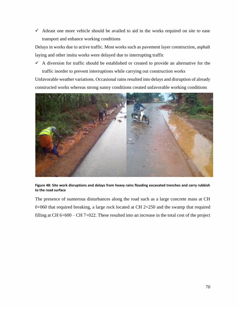
70
Atleast one more vehicle should be availed to aid in the works required on site to ease
transport and enhance working conditions
Delays in works due to active traffic. Most works such as pavement layer construction, asphalt
laying and other insitu works were delayed due to interrupting traffic
A diversion for traffic should be established or created to provide an alternative for the
traffic inorder to prevent interruptions while carrying out construction works
Unfavorable weather variations. Occasional rains resulted into delays and disruption of already
constructed works whereas strong sunny conditions created unfavorable working conditions
Figure 48: Site work disruptions and delays from heavy rains flooding excavated trenches and carry rubbish to the road surface
The presence of numerous disturbances along the road such as a large concrete mass at CH
0+060 that required breaking, a large rock located at CH 2+250 and the swamp that required
filling at CH 6+600 – CH 7+022. These resulted into an increase in the total cost of the project
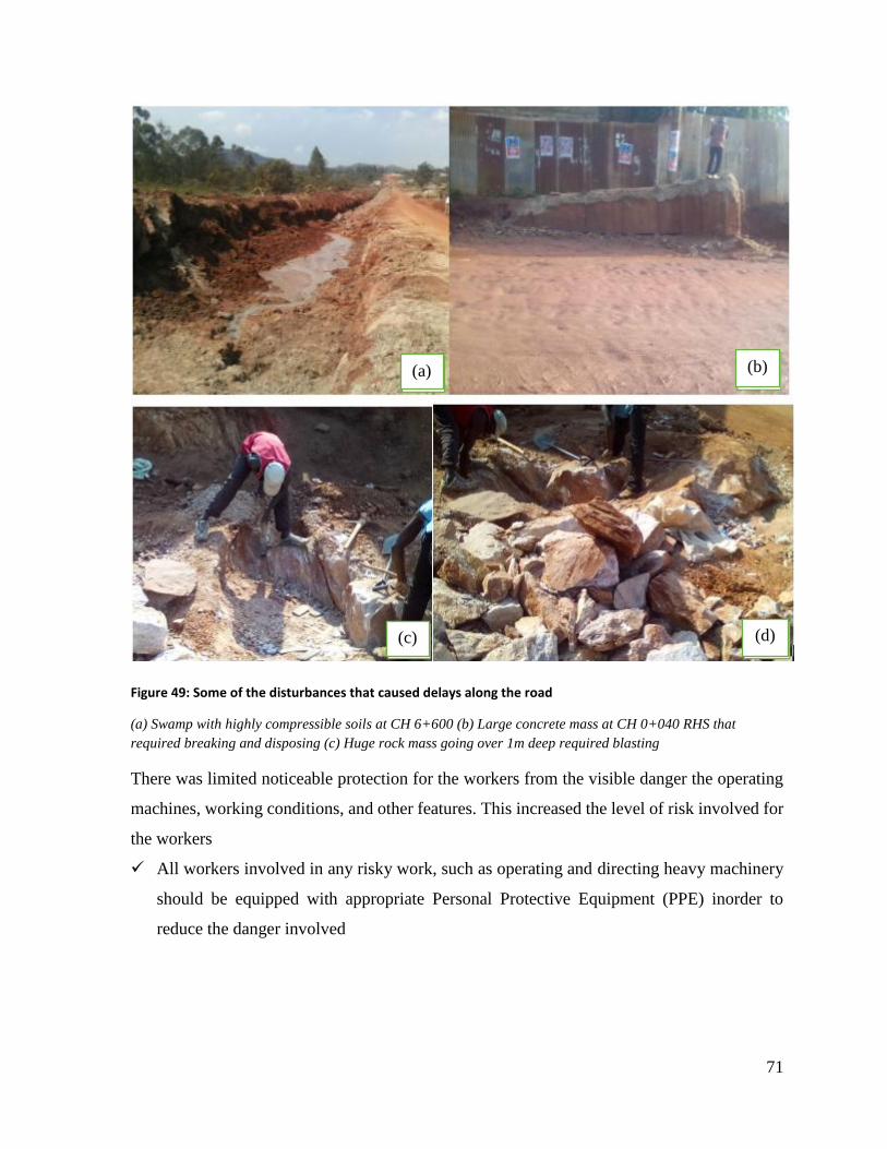
71
Figure 49: Some of the disturbances that caused delays along the road
(a) Swamp with highly compressible soils at CH 6+600 (b) Large concrete mass at CH 0+040 RHS that
required breaking and disposing (c) Huge rock mass going over 1m deep required blasting
There was limited noticeable protection for the workers from the visible danger the operating
machines, working conditions, and other features. This increased the level of risk involved for
the workers
All workers involved in any risky work, such as operating and directing heavy machinery
should be equipped with appropriate Personal Protective Equipment (PPE) inorder to
reduce the danger involved
(a) (b)
(c) (d)

72
4.3 Conclusion
All in all, industrial training was a successful program. The following are some of the strengths
derived from the industrial training such as skills in all aspects like ability to handle tasks
independently, degree of innovativeness, working as a team where necessary with a high
degree of integrity and professionalism.

73
CHAPTER FIVE: REFERENCES Roger L. Brockenbrough, Highway Engineering Handbook 3rd Edition, McGraw Hill books
(2009)
T. F. Fwa, The Handbook of Highway Engineering, Taylor and Francis group, CRC Press (2006)
J.Uren and W.F Price, Surveying for Engineers- 4th Edition.
A Bannister, S Raymond and R Baker, Surveying 6th edition, Longman Scientific & Technical
(1992)
B M Sadgrove and E Danson, Setting-out procedures for the modern built environment, CIRIA
(1997)
Kaddu David CIV3103: Highways Engineering; Year 3 Semester 1, Class notes
Muhindo M Wilson CIV2103: ENGINEERING SURVEY I; Year 2 Semester 1 Surveying Class
notes
CIV2203: ENGINEERING SURVEY 2; Year 2 Semester 2 Surveying Class notes
Central materials laboratory (CML-TZ) testing manual of Tanzania 2000
http://www.onlinemanuals.txdot.gov/txdotmanuals/pdm/pavement_design_reports
http://www.dot.state.oh.us/Divisions/Engineering/Pavement/Pages/Publications.aspx
http://www.civilblog.org