20151210 anritsu pim webinar - slides
TRANSCRIPT

8172019 20151210 Anritsu PIM Webinar - Slides
httpslidepdfcomreaderfull20151210-anritsu-pim-webinar-slides 134
Passive Intermodulation (PIM) concerns in
In-Building Wireless (IBW) networks
Tom Bell
Sr Product Manager
8172019 20151210 Anritsu PIM Webinar - Slides
httpslidepdfcomreaderfull20151210-anritsu-pim-webinar-slides 234
2 Copyrightcopy ANRITSU
Agenda
1 Passive Intermodulation (PIM) review
2
In-building Wireless (IBW) architectures
3 PIM concerns in each IBW architecture
4
Methods to mitigate external PIM5
Conclusions
11410-00885
8172019 20151210 Anritsu PIM Webinar - Slides
httpslidepdfcomreaderfull20151210-anritsu-pim-webinar-slides 334
3 Copyrightcopy ANRITSU
What is Passive Intermodulation (PIM)
Passive Intermodulation (PIM) Passive Intermodulation (PIM)
TX signals at site
PIM = interference
PIM = new frequencies generated by Tx signals when they encounter
non-linear junctions or materials in the RF path
PIM falling in an uplink band can elevate the noise floor
Dropped calls Access failures Slower data rates
Downlink Uplink
8172019 20151210 Anritsu PIM Webinar - Slides
httpslidepdfcomreaderfull20151210-anritsu-pim-webinar-slides 434
What is a non-linear junction
Slide 4
bull Current increases linearly with applied voltage
bull High pressure metal-to-metal contacts
bull Welded or soldered connections C u r r e n t
Voltage
Linear junctions
Non-Linear junctions
C u r r e n t
Voltage
bull Current does not increase linearly with voltage
bull Low pressure metal-to-metal contacts
bull Oxide layers on metal surfaces
bull Arcing across small air gaps or cracks
8172019 20151210 Anritsu PIM Webinar - Slides
httpslidepdfcomreaderfull20151210-anritsu-pim-webinar-slides 534
5 Copyrightcopy ANRITSU
What is non-linear in IBW networks
bull
Poor cable terminationbull Damaged poorly made components
bull High power RF terminations
bull Loose RF connections
bull Type-N connectors
bull
Metal flakes inside connectorsbull Loose metal objects near antennas
8172019 20151210 Anritsu PIM Webinar - Slides
httpslidepdfcomreaderfull20151210-anritsu-pim-webinar-slides 634
Where do PIM frequencies occur
F1 F2
IM 3IM 5IM 7IM 9 IM 3 IM 5 IM 7 IM 9
2F2ndash1F1
3F2ndash2F1
4F2ndash3F1
5F2ndash4F1
2F1ndash1F2
3F1ndash2F2
4F1ndash3F2
5F1ndash4F2
850Downlink
850Uplink
875MHz
885MHz
865MHz
855MHz
845MHz
835MHz
895MHz
905MHz
915MHz
925MHz
900 Uplink
bull Mathematical combinations of the Tx frequencies at a site
bull Odd products fall closer to the Tx frequencies and are more
likely to fall in an operatorrsquos uplink band
8172019 20151210 Anritsu PIM Webinar - Slides
httpslidepdfcomreaderfull20151210-anritsu-pim-webinar-slides 734
F1 F2
IM 4
3F1ndash1F2
900Downlink
950MHz
960
MHz
1890MHz
2100 Uplink
IM 2 IM 4
1F2+1F1
3F2ndash1F1
1915MHz
1930MHz
IM 3 IM 5 IM 6
4F2ndash2F1
1940MHz
4F1ndash2F2
1880MHz
IM 6
IM2 and IM4 can also cause problems
8172019 20151210 Anritsu PIM Webinar - Slides
httpslidepdfcomreaderfull20151210-anritsu-pim-webinar-slides 834
PIM magnitude
Slide 8
X
20 dB
15 dB
15 dB
bull Low order IM products are higher magnitude than high order products
bull Higher magnitude = more likely to cause interference
Downlink Uplink
8172019 20151210 Anritsu PIM Webinar - Slides
httpslidepdfcomreaderfull20151210-anritsu-pim-webinar-slides 934
Europe lt 1 GHz
Slide 9
IM3
IM5
IM5 IM5
800uplink
900downlink
800downlink
900uplink
IM3
$ amp () amp
$ amp ()
amp $ + ()
$ amp ()-
$ ()-
amp $ ()-
$ amp ()-
amp $ amp ()-
amp $ ()-
amp $ + ()-
$ amp ()- amp
amp $ ()- amp
$ amp ()- amp
amp $ + ()- amp
$ + ()- amp
Single Band PIM
Multi Band PIM
IM5
$ amp () amp
$ () amp
amp $ () amp
$ amp () amp
$ () amp
$ + () amp
amp $ + () amp
$ amp ()
$ ()
$ amp ()
$ ()
amp $ ()
amp $ amp ()
$ + ()
amp $ + ()
$ amp ()-
$ ()-
amp $ ()-
amp $ amp ()-
$ amp ()-
$ ()-
amp $ + ()-
$ + ()-
amp $ ()
amp $ amp ()
$ amp ()
amp $ + ()
$ + ()
$ amp ()
$ ()
700uplink
700downlink
IM3
IM5
IM5
8172019 20151210 Anritsu PIM Webinar - Slides
httpslidepdfcomreaderfull20151210-anritsu-pim-webinar-slides 1034
Europe gt1 GHz
Slide 10
IM3 IM3
1800uplink
1800downlink
2100uplink
2100downlink
$ () amp
amp $ () amp
$ + () amp
amp $ ()- amp
amp $ + ()- amp
$ + ()- amp
amp $ ()-
amp $ + ()-
$ amp () amp
amp $ () amp
$ () amp
amp $ amp () amp
Single Band PIM
Multi Band PIM
IM7IM5
$ amp () amp
amp $ amp () amp
$ amp () amp
amp $ () amp
$ + () amp
amp $ amp ()
$ amp ()
amp $ ()
amp $ + ()
$ + ()
$ amp () ampamp $ + () amp
$ + () amp
()
$ ()
amp $ ()
amp $ amp ()
$ amp ()
$ ()
amp $ + ()
$ + ()
8172019 20151210 Anritsu PIM Webinar - Slides
httpslidepdfcomreaderfull20151210-anritsu-pim-webinar-slides 1134
Europe gt1 GHz (cont)
Slide 11
IM3
IM3
2600uplink
TDD 2600 uplink downlink
2600downlink
amp $ amp () +
$ amp ()- +
$ ()- +
amp $ ()- +
amp $ + ()- +
$ + ()- +
amp $ amp () +
amp $ () +
Single Band PIM
Multi Band PIM
IM5
$ amp () +
$ () +
amp $ () +
$ amp () +
amp $ amp () +
$ amp () +
amp $ () +
$ + () +
amp $ () +amp $ + () +
$ + () +
IM5
8172019 20151210 Anritsu PIM Webinar - Slides
httpslidepdfcomreaderfull20151210-anritsu-pim-webinar-slides 1234
PIM bandwidth
F1 F2IM 3IM 5IM 7IM 9 IM 3 IM 5 IM 7 IM 9
200 KHz200 KHz
600 KHz
1 MHz
14 MHz
18 MHz
600 KHz
1 MHz
14 MHz
18 MHz
bull PIM bandwidth increases as carrier bandwidth increases
bull PIM bandwidth increases with PIM order
X
3X
5X
7X
9X
3X
5X
7X
9X
X
8172019 20151210 Anritsu PIM Webinar - Slides
httpslidepdfcomreaderfull20151210-anritsu-pim-webinar-slides 1334
PIM generated by single LTE carrier
bull LTE carrier is composed of individual sub-carrier frequencies
Carrier bandwidth = X
IM3 bandwidth = 3X
IM5 bandwidth = 5X
IM7 bandwidth = 7X
IM9 bandwidth = 9X
IM 3
IM 5IM 7
IM 9
X
X
XX
XX
XX
X
LTE
carrier
8172019 20151210 Anritsu PIM Webinar - Slides
httpslidepdfcomreaderfull20151210-anritsu-pim-webinar-slides 1434
And donrsquot forget the even products
900Downlink 2100 Uplink
IM 3
IM 5
IM 7
IM 2
IM 4
IM 6
bull LTE carrier is composed of individual sub-carrier frequencies
Carrier bandwidth = X
IM2 bandwidth = 2X
IM4 bandwidth = 4X
IM6 bandwidth = 6X
IM8 bandwidth = 8X
8172019 20151210 Anritsu PIM Webinar - Slides
httpslidepdfcomreaderfull20151210-anritsu-pim-webinar-slides 1534
700 MHz LTE example (North America)
Slide 15
bull
PIM generated by single LTE carrier
bull Viewed through Rx monitor port
bull
This was a very bad PIM source
25 dB
8172019 20151210 Anritsu PIM Webinar - Slides
httpslidepdfcomreaderfull20151210-anritsu-pim-webinar-slides 1634
What about TDD- LTE
Slide 16
25 dB
Synchronized TDD
Un-synchronized TDD
bull TDD systems Tx and Rx are at diff erenttimes
bull PIM is only produced while transmitting
bull
PIM is only an issue for adjacent bands
bull Adjacent TDD bands should be
synchronized to prevent interference
8172019 20151210 Anritsu PIM Webinar - Slides
httpslidepdfcomreaderfull20151210-anritsu-pim-webinar-slides 1734
How can we reduce PIM interference
Slide 17
-57 dBm
-100 dBc -150 dBc
F1 F243 dBm
-107 dBm
F1 F2
More linear
bull Loose RF connector
bull
Metal 1047298akes in connectors
bull Braided cables
bull Antenna near PIM source
bull Tight RF connector
bull
Connectors clean
bull Corrugated cables
bull Antenna re-located
More linear
Improve linearity
8172019 20151210 Anritsu PIM Webinar - Slides
httpslidepdfcomreaderfull20151210-anritsu-pim-webinar-slides 1834
How do we measure linearity
18
With a PIM tester
Inject two CW test signals at a known magnitude
Measure 3rd order intermodulation product (IM3)
IM3 ldquocharacterizesrdquo the linearity of the system
bull
If IM3 is low = linearity is good
bull
If IM3 is high = linearity is bad
8172019 20151210 Anritsu PIM Webinar - Slides
httpslidepdfcomreaderfull20151210-anritsu-pim-webinar-slides 1934
19 Copyrightcopy ANRITSU
What determines PIM severity to an IBW operator
1
Which IM product(s) fall in the uplink band
A
Low order IM products in uplink = higher uplink noise
B
More frequency bands operators = higher probability
of low order product in uplink band
2
Degree of non-linearity of PIM source A
More non-linear = higher PIM magnitude
3
Level of current flowing through non-linear junction material
A
Higher current = higher PIM magnitude
B
Higher RF power level = higher PIM magnitude
C
PIM source location orientation
D
PIM source distance from antenna
8172019 20151210 Anritsu PIM Webinar - Slides
httpslidepdfcomreaderfull20151210-anritsu-pim-webinar-slides 2034
20 Copyrightcopy ANRITSU
In-Building Wireless (IBW) system architectures
Distributed Small Cell (DSC)
Distributed Antenna System (DAS)
bull Passive
bull Active
bull Hybrid
bull Analog Digital
Distributed Radio System (DRS)
8172019 20151210 Anritsu PIM Webinar - Slides
httpslidepdfcomreaderfull20151210-anritsu-pim-webinar-slides 2134
21 Copyrightcopy ANRITSU
Passive DAS
RF cable distributionthroughout
Signal source
High power single band
(20W)
Floor
Mediumpower multi
band (1W)
Antenna
Low power multi band
(100mW)
BTS
RRH
Widebandantennas
Repeater BDA
PIM
PIM
PIM
Combiner
Donor antenna
MoreSevere
LessSevere
PIM
After combinerHigh power
multi band
8172019 20151210 Anritsu PIM Webinar - Slides
httpslidepdfcomreaderfull20151210-anritsu-pim-webinar-slides 2234
22 Copyrightcopy ANRITSU
Active DAS
Optical 1047297berdistribution
network
After POI TraySimplex low
power (1mW)POI Tray
BTS
RRH
Head EndEquipment
Radio Units
Wideband antennas
PIM
PIM
PIM
PIM Severe
LessSevere
Signal sourceHigh power
single band
(20W)
AntennaLow power
multi band
(100mW)
8172019 20151210 Anritsu PIM Webinar - Slides
httpslidepdfcomreaderfull20151210-anritsu-pim-webinar-slides 2334
23 Copyrightcopy ANRITSU
Hybrid DAS
PIM
PIM
PIM
MoreSevere
LessSevere
BTS
RRH
Widebandantennas
Radio Units
Optical 1047297berdistribution
network
After POI TraySimplex low
power (1mW)
POI Tray
Head EndEquipment
PIM
PIM
Signal sourceHigh power
single band
(20W)
AntennaLow power
multi band
(100mW)
FloorMedium
power multi
band (1W)
8172019 20151210 Anritsu PIM Webinar - Slides
httpslidepdfcomreaderfull20151210-anritsu-pim-webinar-slides 2434
24 Copyrightcopy ANRITSU
Digital Active DAS
Optical 1047297berdistribution
network
Digital SignalSources
POI Tray
BTS
BBUHead EndEquipment
Expansion Units
Wideband antennas
PIM
PIM
PIM
PIMSevere
LessSevere
RF Signal sourceHigh power single
band (20W)
AntennaLow power
multi band
(100mW)
LAN cabledistribution
network PIM
C-RAN
8172019 20151210 Anritsu PIM Webinar - Slides
httpslidepdfcomreaderfull20151210-anritsu-pim-webinar-slides 2534
25 Copyrightcopy ANRITSU
Distributed Radio System (DRS)
Radio Units withintegrated antenna
Expansion Unit
Base Band Unit(BBU)
Optical 1047297berdistribution
network PIM
PIM
Low power single band
(100mW)
MoreSevere
LessSevere
Low power multi band
(100mW)
PIM
LAN cabledistribution
network
PIM
8172019 20151210 Anritsu PIM Webinar - Slides
httpslidepdfcomreaderfull20151210-anritsu-pim-webinar-slides 2634
26 Copyrightcopy ANRITSU
Distributed Small Cells (DSC)
Small Cell withintegrated antenna
EthernetSwitches
Localcontroller
LAN cabledistribution
network PIM
PIM
Low power single band
(100mW)
MoreSevere
LessSevere
Core Network
Low power multi band
(100mW)
PIM
8172019 20151210 Anritsu PIM Webinar - Slides
httpslidepdfcomreaderfull20151210-anritsu-pim-webinar-slides 2734
27 Copyrightcopy ANRITSU
Is external PIM really a concern below 100 mW
bull External PIM measured while walking across office environment
bull 700 850 1900 amp 2600 MHz PIM test signals combined
bull Signi1047297cant PIM at low frequencies even with 15 dBm (32 mW) Tx power
Indoor antenna
8172019 20151210 Anritsu PIM Webinar - Slides
httpslidepdfcomreaderfull20151210-anritsu-pim-webinar-slides 2834
28 Copyrightcopy ANRITSU
How can I prevent PIM problems in IBW systems
1
Avoid frequency combinations that create low orderIM products in uplink bands
2
Use low PIM construction techniques materials
3
Avoid non-linear objects near antennas
1 and 3 above may be outside of your control
bull Multi-operator requirements
bull
Aesthetic requirements
8172019 20151210 Anritsu PIM Webinar - Slides
httpslidepdfcomreaderfull20151210-anritsu-pim-webinar-slides 2934
29 Copyrightcopy ANRITSU
Methods to mitigate external PIM1) Move the antenna
bull Non-linear objects in antenna near 1047297eld generate higher PIM
bull Moving antenna a short distance moves PIM source to far 1047297eld
bull At 20 dBm (100mW) PIM reduced gt60 dB when antenna moved 05m
Indoor antennaDiode
Near1047297eld
Far 1047297eld
8172019 20151210 Anritsu PIM Webinar - Slides
httpslidepdfcomreaderfull20151210-anritsu-pim-webinar-slides 3034
30 Copyrightcopy ANRITSU
2) Move the PIM Source
bull Electrical conduit added after DAS was
installed and commissioned
bull Safety cables lightly touching metal
surfaces on near antenna
8172019 20151210 Anritsu PIM Webinar - Slides
httpslidepdfcomreaderfull20151210-anritsu-pim-webinar-slides 3134
31 Copyrightcopy ANRITSU
3) Add attenuation between antenna amp PIM sourcePIM source
PIM source covered with Aluminum duct tape
gt40 dB PIM reduction
8172019 20151210 Anritsu PIM Webinar - Slides
httpslidepdfcomreaderfull20151210-anritsu-pim-webinar-slides 3234
32 Copyrightcopy ANRITSU
4) Direct less power at PIM source
bull Antenna with ldquonotchrdquo in horizontal pattern
bull
Rotate antenna to steer null at PIM source
bull Up to 30 dB reduction in PIM
DiodeRotate antenna
JMA Wireless
8172019 20151210 Anritsu PIM Webinar - Slides
httpslidepdfcomreaderfull20151210-anritsu-pim-webinar-slides 3334
33 Copyrightcopy ANRITSU
Summary
bull
PIM severity will be different for each IBW installation
bull
Type of construction
bull
Frequency bands in use
bull
Power levels in use
bull
PIM can be a problem even at very low power levels
bull
PIM can be mitigated by
bull
Eliminating ldquobadrdquo frequency combinations
bull
Using low PIM construction techniques materials
bull
Reducing RF energy arriving at the PIM source
8172019 20151210 Anritsu PIM Webinar - Slides
httpslidepdfcomreaderfull20151210-anritsu-pim-webinar-slides 3434

8172019 20151210 Anritsu PIM Webinar - Slides
httpslidepdfcomreaderfull20151210-anritsu-pim-webinar-slides 634
Where do PIM frequencies occur
F1 F2
IM 3IM 5IM 7IM 9 IM 3 IM 5 IM 7 IM 9
2F2ndash1F1
3F2ndash2F1
4F2ndash3F1
5F2ndash4F1
2F1ndash1F2
3F1ndash2F2
4F1ndash3F2
5F1ndash4F2
850Downlink
850Uplink
875MHz
885MHz
865MHz
855MHz
845MHz
835MHz
895MHz
905MHz
915MHz
925MHz
900 Uplink
bull Mathematical combinations of the Tx frequencies at a site
bull Odd products fall closer to the Tx frequencies and are more
likely to fall in an operatorrsquos uplink band
8172019 20151210 Anritsu PIM Webinar - Slides
httpslidepdfcomreaderfull20151210-anritsu-pim-webinar-slides 734
F1 F2
IM 4
3F1ndash1F2
900Downlink
950MHz
960
MHz
1890MHz
2100 Uplink
IM 2 IM 4
1F2+1F1
3F2ndash1F1
1915MHz
1930MHz
IM 3 IM 5 IM 6
4F2ndash2F1
1940MHz
4F1ndash2F2
1880MHz
IM 6
IM2 and IM4 can also cause problems
8172019 20151210 Anritsu PIM Webinar - Slides
httpslidepdfcomreaderfull20151210-anritsu-pim-webinar-slides 834
PIM magnitude
Slide 8
X
20 dB
15 dB
15 dB
bull Low order IM products are higher magnitude than high order products
bull Higher magnitude = more likely to cause interference
Downlink Uplink
8172019 20151210 Anritsu PIM Webinar - Slides
httpslidepdfcomreaderfull20151210-anritsu-pim-webinar-slides 934
Europe lt 1 GHz
Slide 9
IM3
IM5
IM5 IM5
800uplink
900downlink
800downlink
900uplink
IM3
$ amp () amp
$ amp ()
amp $ + ()
$ amp ()-
$ ()-
amp $ ()-
$ amp ()-
amp $ amp ()-
amp $ ()-
amp $ + ()-
$ amp ()- amp
amp $ ()- amp
$ amp ()- amp
amp $ + ()- amp
$ + ()- amp
Single Band PIM
Multi Band PIM
IM5
$ amp () amp
$ () amp
amp $ () amp
$ amp () amp
$ () amp
$ + () amp
amp $ + () amp
$ amp ()
$ ()
$ amp ()
$ ()
amp $ ()
amp $ amp ()
$ + ()
amp $ + ()
$ amp ()-
$ ()-
amp $ ()-
amp $ amp ()-
$ amp ()-
$ ()-
amp $ + ()-
$ + ()-
amp $ ()
amp $ amp ()
$ amp ()
amp $ + ()
$ + ()
$ amp ()
$ ()
700uplink
700downlink
IM3
IM5
IM5
8172019 20151210 Anritsu PIM Webinar - Slides
httpslidepdfcomreaderfull20151210-anritsu-pim-webinar-slides 1034
Europe gt1 GHz
Slide 10
IM3 IM3
1800uplink
1800downlink
2100uplink
2100downlink
$ () amp
amp $ () amp
$ + () amp
amp $ ()- amp
amp $ + ()- amp
$ + ()- amp
amp $ ()-
amp $ + ()-
$ amp () amp
amp $ () amp
$ () amp
amp $ amp () amp
Single Band PIM
Multi Band PIM
IM7IM5
$ amp () amp
amp $ amp () amp
$ amp () amp
amp $ () amp
$ + () amp
amp $ amp ()
$ amp ()
amp $ ()
amp $ + ()
$ + ()
$ amp () ampamp $ + () amp
$ + () amp
()
$ ()
amp $ ()
amp $ amp ()
$ amp ()
$ ()
amp $ + ()
$ + ()
8172019 20151210 Anritsu PIM Webinar - Slides
httpslidepdfcomreaderfull20151210-anritsu-pim-webinar-slides 1134
Europe gt1 GHz (cont)
Slide 11
IM3
IM3
2600uplink
TDD 2600 uplink downlink
2600downlink
amp $ amp () +
$ amp ()- +
$ ()- +
amp $ ()- +
amp $ + ()- +
$ + ()- +
amp $ amp () +
amp $ () +
Single Band PIM
Multi Band PIM
IM5
$ amp () +
$ () +
amp $ () +
$ amp () +
amp $ amp () +
$ amp () +
amp $ () +
$ + () +
amp $ () +amp $ + () +
$ + () +
IM5
8172019 20151210 Anritsu PIM Webinar - Slides
httpslidepdfcomreaderfull20151210-anritsu-pim-webinar-slides 1234
PIM bandwidth
F1 F2IM 3IM 5IM 7IM 9 IM 3 IM 5 IM 7 IM 9
200 KHz200 KHz
600 KHz
1 MHz
14 MHz
18 MHz
600 KHz
1 MHz
14 MHz
18 MHz
bull PIM bandwidth increases as carrier bandwidth increases
bull PIM bandwidth increases with PIM order
X
3X
5X
7X
9X
3X
5X
7X
9X
X
8172019 20151210 Anritsu PIM Webinar - Slides
httpslidepdfcomreaderfull20151210-anritsu-pim-webinar-slides 1334
PIM generated by single LTE carrier
bull LTE carrier is composed of individual sub-carrier frequencies
Carrier bandwidth = X
IM3 bandwidth = 3X
IM5 bandwidth = 5X
IM7 bandwidth = 7X
IM9 bandwidth = 9X
IM 3
IM 5IM 7
IM 9
X
X
XX
XX
XX
X
LTE
carrier
8172019 20151210 Anritsu PIM Webinar - Slides
httpslidepdfcomreaderfull20151210-anritsu-pim-webinar-slides 1434
And donrsquot forget the even products
900Downlink 2100 Uplink
IM 3
IM 5
IM 7
IM 2
IM 4
IM 6
bull LTE carrier is composed of individual sub-carrier frequencies
Carrier bandwidth = X
IM2 bandwidth = 2X
IM4 bandwidth = 4X
IM6 bandwidth = 6X
IM8 bandwidth = 8X
8172019 20151210 Anritsu PIM Webinar - Slides
httpslidepdfcomreaderfull20151210-anritsu-pim-webinar-slides 1534
700 MHz LTE example (North America)
Slide 15
bull
PIM generated by single LTE carrier
bull Viewed through Rx monitor port
bull
This was a very bad PIM source
25 dB
8172019 20151210 Anritsu PIM Webinar - Slides
httpslidepdfcomreaderfull20151210-anritsu-pim-webinar-slides 1634
What about TDD- LTE
Slide 16
25 dB
Synchronized TDD
Un-synchronized TDD
bull TDD systems Tx and Rx are at diff erenttimes
bull PIM is only produced while transmitting
bull
PIM is only an issue for adjacent bands
bull Adjacent TDD bands should be
synchronized to prevent interference
8172019 20151210 Anritsu PIM Webinar - Slides
httpslidepdfcomreaderfull20151210-anritsu-pim-webinar-slides 1734
How can we reduce PIM interference
Slide 17
-57 dBm
-100 dBc -150 dBc
F1 F243 dBm
-107 dBm
F1 F2
More linear
bull Loose RF connector
bull
Metal 1047298akes in connectors
bull Braided cables
bull Antenna near PIM source
bull Tight RF connector
bull
Connectors clean
bull Corrugated cables
bull Antenna re-located
More linear
Improve linearity
8172019 20151210 Anritsu PIM Webinar - Slides
httpslidepdfcomreaderfull20151210-anritsu-pim-webinar-slides 1834
How do we measure linearity
18
With a PIM tester
Inject two CW test signals at a known magnitude
Measure 3rd order intermodulation product (IM3)
IM3 ldquocharacterizesrdquo the linearity of the system
bull
If IM3 is low = linearity is good
bull
If IM3 is high = linearity is bad
8172019 20151210 Anritsu PIM Webinar - Slides
httpslidepdfcomreaderfull20151210-anritsu-pim-webinar-slides 1934
19 Copyrightcopy ANRITSU
What determines PIM severity to an IBW operator
1
Which IM product(s) fall in the uplink band
A
Low order IM products in uplink = higher uplink noise
B
More frequency bands operators = higher probability
of low order product in uplink band
2
Degree of non-linearity of PIM source A
More non-linear = higher PIM magnitude
3
Level of current flowing through non-linear junction material
A
Higher current = higher PIM magnitude
B
Higher RF power level = higher PIM magnitude
C
PIM source location orientation
D
PIM source distance from antenna
8172019 20151210 Anritsu PIM Webinar - Slides
httpslidepdfcomreaderfull20151210-anritsu-pim-webinar-slides 2034
20 Copyrightcopy ANRITSU
In-Building Wireless (IBW) system architectures
Distributed Small Cell (DSC)
Distributed Antenna System (DAS)
bull Passive
bull Active
bull Hybrid
bull Analog Digital
Distributed Radio System (DRS)
8172019 20151210 Anritsu PIM Webinar - Slides
httpslidepdfcomreaderfull20151210-anritsu-pim-webinar-slides 2134
21 Copyrightcopy ANRITSU
Passive DAS
RF cable distributionthroughout
Signal source
High power single band
(20W)
Floor
Mediumpower multi
band (1W)
Antenna
Low power multi band
(100mW)
BTS
RRH
Widebandantennas
Repeater BDA
PIM
PIM
PIM
Combiner
Donor antenna
MoreSevere
LessSevere
PIM
After combinerHigh power
multi band
8172019 20151210 Anritsu PIM Webinar - Slides
httpslidepdfcomreaderfull20151210-anritsu-pim-webinar-slides 2234
22 Copyrightcopy ANRITSU
Active DAS
Optical 1047297berdistribution
network
After POI TraySimplex low
power (1mW)POI Tray
BTS
RRH
Head EndEquipment
Radio Units
Wideband antennas
PIM
PIM
PIM
PIM Severe
LessSevere
Signal sourceHigh power
single band
(20W)
AntennaLow power
multi band
(100mW)
8172019 20151210 Anritsu PIM Webinar - Slides
httpslidepdfcomreaderfull20151210-anritsu-pim-webinar-slides 2334
23 Copyrightcopy ANRITSU
Hybrid DAS
PIM
PIM
PIM
MoreSevere
LessSevere
BTS
RRH
Widebandantennas
Radio Units
Optical 1047297berdistribution
network
After POI TraySimplex low
power (1mW)
POI Tray
Head EndEquipment
PIM
PIM
Signal sourceHigh power
single band
(20W)
AntennaLow power
multi band
(100mW)
FloorMedium
power multi
band (1W)
8172019 20151210 Anritsu PIM Webinar - Slides
httpslidepdfcomreaderfull20151210-anritsu-pim-webinar-slides 2434
24 Copyrightcopy ANRITSU
Digital Active DAS
Optical 1047297berdistribution
network
Digital SignalSources
POI Tray
BTS
BBUHead EndEquipment
Expansion Units
Wideband antennas
PIM
PIM
PIM
PIMSevere
LessSevere
RF Signal sourceHigh power single
band (20W)
AntennaLow power
multi band
(100mW)
LAN cabledistribution
network PIM
C-RAN
8172019 20151210 Anritsu PIM Webinar - Slides
httpslidepdfcomreaderfull20151210-anritsu-pim-webinar-slides 2534
25 Copyrightcopy ANRITSU
Distributed Radio System (DRS)
Radio Units withintegrated antenna
Expansion Unit
Base Band Unit(BBU)
Optical 1047297berdistribution
network PIM
PIM
Low power single band
(100mW)
MoreSevere
LessSevere
Low power multi band
(100mW)
PIM
LAN cabledistribution
network
PIM
8172019 20151210 Anritsu PIM Webinar - Slides
httpslidepdfcomreaderfull20151210-anritsu-pim-webinar-slides 2634
26 Copyrightcopy ANRITSU
Distributed Small Cells (DSC)
Small Cell withintegrated antenna
EthernetSwitches
Localcontroller
LAN cabledistribution
network PIM
PIM
Low power single band
(100mW)
MoreSevere
LessSevere
Core Network
Low power multi band
(100mW)
PIM
8172019 20151210 Anritsu PIM Webinar - Slides
httpslidepdfcomreaderfull20151210-anritsu-pim-webinar-slides 2734
27 Copyrightcopy ANRITSU
Is external PIM really a concern below 100 mW
bull External PIM measured while walking across office environment
bull 700 850 1900 amp 2600 MHz PIM test signals combined
bull Signi1047297cant PIM at low frequencies even with 15 dBm (32 mW) Tx power
Indoor antenna
8172019 20151210 Anritsu PIM Webinar - Slides
httpslidepdfcomreaderfull20151210-anritsu-pim-webinar-slides 2834
28 Copyrightcopy ANRITSU
How can I prevent PIM problems in IBW systems
1
Avoid frequency combinations that create low orderIM products in uplink bands
2
Use low PIM construction techniques materials
3
Avoid non-linear objects near antennas
1 and 3 above may be outside of your control
bull Multi-operator requirements
bull
Aesthetic requirements
8172019 20151210 Anritsu PIM Webinar - Slides
httpslidepdfcomreaderfull20151210-anritsu-pim-webinar-slides 2934
29 Copyrightcopy ANRITSU
Methods to mitigate external PIM1) Move the antenna
bull Non-linear objects in antenna near 1047297eld generate higher PIM
bull Moving antenna a short distance moves PIM source to far 1047297eld
bull At 20 dBm (100mW) PIM reduced gt60 dB when antenna moved 05m
Indoor antennaDiode
Near1047297eld
Far 1047297eld
8172019 20151210 Anritsu PIM Webinar - Slides
httpslidepdfcomreaderfull20151210-anritsu-pim-webinar-slides 3034
30 Copyrightcopy ANRITSU
2) Move the PIM Source
bull Electrical conduit added after DAS was
installed and commissioned
bull Safety cables lightly touching metal
surfaces on near antenna
8172019 20151210 Anritsu PIM Webinar - Slides
httpslidepdfcomreaderfull20151210-anritsu-pim-webinar-slides 3134
31 Copyrightcopy ANRITSU
3) Add attenuation between antenna amp PIM sourcePIM source
PIM source covered with Aluminum duct tape
gt40 dB PIM reduction
8172019 20151210 Anritsu PIM Webinar - Slides
httpslidepdfcomreaderfull20151210-anritsu-pim-webinar-slides 3234
32 Copyrightcopy ANRITSU
4) Direct less power at PIM source
bull Antenna with ldquonotchrdquo in horizontal pattern
bull
Rotate antenna to steer null at PIM source
bull Up to 30 dB reduction in PIM
DiodeRotate antenna
JMA Wireless
8172019 20151210 Anritsu PIM Webinar - Slides
httpslidepdfcomreaderfull20151210-anritsu-pim-webinar-slides 3334
33 Copyrightcopy ANRITSU
Summary
bull
PIM severity will be different for each IBW installation
bull
Type of construction
bull
Frequency bands in use
bull
Power levels in use
bull
PIM can be a problem even at very low power levels
bull
PIM can be mitigated by
bull
Eliminating ldquobadrdquo frequency combinations
bull
Using low PIM construction techniques materials
bull
Reducing RF energy arriving at the PIM source
8172019 20151210 Anritsu PIM Webinar - Slides
httpslidepdfcomreaderfull20151210-anritsu-pim-webinar-slides 3434
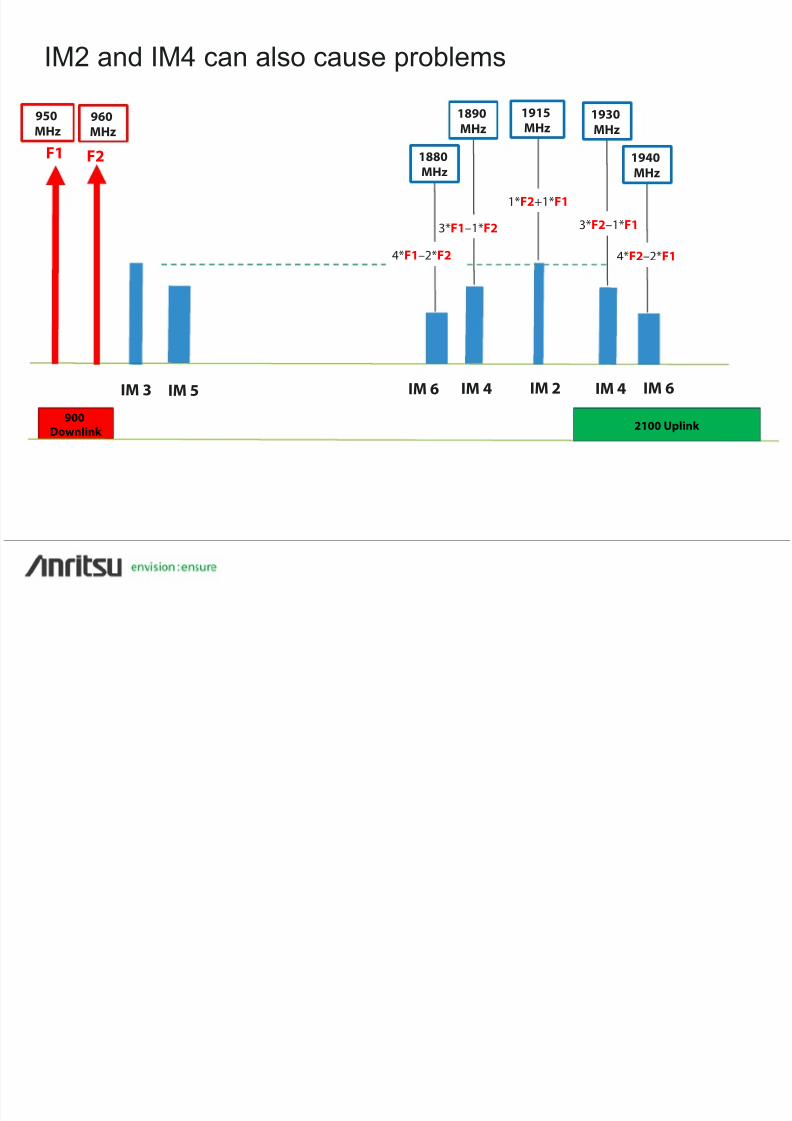
8172019 20151210 Anritsu PIM Webinar - Slides
httpslidepdfcomreaderfull20151210-anritsu-pim-webinar-slides 1434
And donrsquot forget the even products
900Downlink 2100 Uplink
IM 3
IM 5
IM 7
IM 2
IM 4
IM 6
bull LTE carrier is composed of individual sub-carrier frequencies
Carrier bandwidth = X
IM2 bandwidth = 2X
IM4 bandwidth = 4X
IM6 bandwidth = 6X
IM8 bandwidth = 8X
8172019 20151210 Anritsu PIM Webinar - Slides
httpslidepdfcomreaderfull20151210-anritsu-pim-webinar-slides 1534
700 MHz LTE example (North America)
Slide 15
bull
PIM generated by single LTE carrier
bull Viewed through Rx monitor port
bull
This was a very bad PIM source
25 dB
8172019 20151210 Anritsu PIM Webinar - Slides
httpslidepdfcomreaderfull20151210-anritsu-pim-webinar-slides 1634
What about TDD- LTE
Slide 16
25 dB
Synchronized TDD
Un-synchronized TDD
bull TDD systems Tx and Rx are at diff erenttimes
bull PIM is only produced while transmitting
bull
PIM is only an issue for adjacent bands
bull Adjacent TDD bands should be
synchronized to prevent interference
8172019 20151210 Anritsu PIM Webinar - Slides
httpslidepdfcomreaderfull20151210-anritsu-pim-webinar-slides 1734
How can we reduce PIM interference
Slide 17
-57 dBm
-100 dBc -150 dBc
F1 F243 dBm
-107 dBm
F1 F2
More linear
bull Loose RF connector
bull
Metal 1047298akes in connectors
bull Braided cables
bull Antenna near PIM source
bull Tight RF connector
bull
Connectors clean
bull Corrugated cables
bull Antenna re-located
More linear
Improve linearity
8172019 20151210 Anritsu PIM Webinar - Slides
httpslidepdfcomreaderfull20151210-anritsu-pim-webinar-slides 1834
How do we measure linearity
18
With a PIM tester
Inject two CW test signals at a known magnitude
Measure 3rd order intermodulation product (IM3)
IM3 ldquocharacterizesrdquo the linearity of the system
bull
If IM3 is low = linearity is good
bull
If IM3 is high = linearity is bad
8172019 20151210 Anritsu PIM Webinar - Slides
httpslidepdfcomreaderfull20151210-anritsu-pim-webinar-slides 1934
19 Copyrightcopy ANRITSU
What determines PIM severity to an IBW operator
1
Which IM product(s) fall in the uplink band
A
Low order IM products in uplink = higher uplink noise
B
More frequency bands operators = higher probability
of low order product in uplink band
2
Degree of non-linearity of PIM source A
More non-linear = higher PIM magnitude
3
Level of current flowing through non-linear junction material
A
Higher current = higher PIM magnitude
B
Higher RF power level = higher PIM magnitude
C
PIM source location orientation
D
PIM source distance from antenna
8172019 20151210 Anritsu PIM Webinar - Slides
httpslidepdfcomreaderfull20151210-anritsu-pim-webinar-slides 2034
20 Copyrightcopy ANRITSU
In-Building Wireless (IBW) system architectures
Distributed Small Cell (DSC)
Distributed Antenna System (DAS)
bull Passive
bull Active
bull Hybrid
bull Analog Digital
Distributed Radio System (DRS)
8172019 20151210 Anritsu PIM Webinar - Slides
httpslidepdfcomreaderfull20151210-anritsu-pim-webinar-slides 2134
21 Copyrightcopy ANRITSU
Passive DAS
RF cable distributionthroughout
Signal source
High power single band
(20W)
Floor
Mediumpower multi
band (1W)
Antenna
Low power multi band
(100mW)
BTS
RRH
Widebandantennas
Repeater BDA
PIM
PIM
PIM
Combiner
Donor antenna
MoreSevere
LessSevere
PIM
After combinerHigh power
multi band
8172019 20151210 Anritsu PIM Webinar - Slides
httpslidepdfcomreaderfull20151210-anritsu-pim-webinar-slides 2234
22 Copyrightcopy ANRITSU
Active DAS
Optical 1047297berdistribution
network
After POI TraySimplex low
power (1mW)POI Tray
BTS
RRH
Head EndEquipment
Radio Units
Wideband antennas
PIM
PIM
PIM
PIM Severe
LessSevere
Signal sourceHigh power
single band
(20W)
AntennaLow power
multi band
(100mW)
8172019 20151210 Anritsu PIM Webinar - Slides
httpslidepdfcomreaderfull20151210-anritsu-pim-webinar-slides 2334
23 Copyrightcopy ANRITSU
Hybrid DAS
PIM
PIM
PIM
MoreSevere
LessSevere
BTS
RRH
Widebandantennas
Radio Units
Optical 1047297berdistribution
network
After POI TraySimplex low
power (1mW)
POI Tray
Head EndEquipment
PIM
PIM
Signal sourceHigh power
single band
(20W)
AntennaLow power
multi band
(100mW)
FloorMedium
power multi
band (1W)
8172019 20151210 Anritsu PIM Webinar - Slides
httpslidepdfcomreaderfull20151210-anritsu-pim-webinar-slides 2434
24 Copyrightcopy ANRITSU
Digital Active DAS
Optical 1047297berdistribution
network
Digital SignalSources
POI Tray
BTS
BBUHead EndEquipment
Expansion Units
Wideband antennas
PIM
PIM
PIM
PIMSevere
LessSevere
RF Signal sourceHigh power single
band (20W)
AntennaLow power
multi band
(100mW)
LAN cabledistribution
network PIM
C-RAN
8172019 20151210 Anritsu PIM Webinar - Slides
httpslidepdfcomreaderfull20151210-anritsu-pim-webinar-slides 2534
25 Copyrightcopy ANRITSU
Distributed Radio System (DRS)
Radio Units withintegrated antenna
Expansion Unit
Base Band Unit(BBU)
Optical 1047297berdistribution
network PIM
PIM
Low power single band
(100mW)
MoreSevere
LessSevere
Low power multi band
(100mW)
PIM
LAN cabledistribution
network
PIM
8172019 20151210 Anritsu PIM Webinar - Slides
httpslidepdfcomreaderfull20151210-anritsu-pim-webinar-slides 2634
26 Copyrightcopy ANRITSU
Distributed Small Cells (DSC)
Small Cell withintegrated antenna
EthernetSwitches
Localcontroller
LAN cabledistribution
network PIM
PIM
Low power single band
(100mW)
MoreSevere
LessSevere
Core Network
Low power multi band
(100mW)
PIM
8172019 20151210 Anritsu PIM Webinar - Slides
httpslidepdfcomreaderfull20151210-anritsu-pim-webinar-slides 2734
27 Copyrightcopy ANRITSU
Is external PIM really a concern below 100 mW
bull External PIM measured while walking across office environment
bull 700 850 1900 amp 2600 MHz PIM test signals combined
bull Signi1047297cant PIM at low frequencies even with 15 dBm (32 mW) Tx power
Indoor antenna
8172019 20151210 Anritsu PIM Webinar - Slides
httpslidepdfcomreaderfull20151210-anritsu-pim-webinar-slides 2834
28 Copyrightcopy ANRITSU
How can I prevent PIM problems in IBW systems
1
Avoid frequency combinations that create low orderIM products in uplink bands
2
Use low PIM construction techniques materials
3
Avoid non-linear objects near antennas
1 and 3 above may be outside of your control
bull Multi-operator requirements
bull
Aesthetic requirements
8172019 20151210 Anritsu PIM Webinar - Slides
httpslidepdfcomreaderfull20151210-anritsu-pim-webinar-slides 2934
29 Copyrightcopy ANRITSU
Methods to mitigate external PIM1) Move the antenna
bull Non-linear objects in antenna near 1047297eld generate higher PIM
bull Moving antenna a short distance moves PIM source to far 1047297eld
bull At 20 dBm (100mW) PIM reduced gt60 dB when antenna moved 05m
Indoor antennaDiode
Near1047297eld
Far 1047297eld
8172019 20151210 Anritsu PIM Webinar - Slides
httpslidepdfcomreaderfull20151210-anritsu-pim-webinar-slides 3034
30 Copyrightcopy ANRITSU
2) Move the PIM Source
bull Electrical conduit added after DAS was
installed and commissioned
bull Safety cables lightly touching metal
surfaces on near antenna
8172019 20151210 Anritsu PIM Webinar - Slides
httpslidepdfcomreaderfull20151210-anritsu-pim-webinar-slides 3134
31 Copyrightcopy ANRITSU
3) Add attenuation between antenna amp PIM sourcePIM source
PIM source covered with Aluminum duct tape
gt40 dB PIM reduction
8172019 20151210 Anritsu PIM Webinar - Slides
httpslidepdfcomreaderfull20151210-anritsu-pim-webinar-slides 3234
32 Copyrightcopy ANRITSU
4) Direct less power at PIM source
bull Antenna with ldquonotchrdquo in horizontal pattern
bull
Rotate antenna to steer null at PIM source
bull Up to 30 dB reduction in PIM
DiodeRotate antenna
JMA Wireless
8172019 20151210 Anritsu PIM Webinar - Slides
httpslidepdfcomreaderfull20151210-anritsu-pim-webinar-slides 3334
33 Copyrightcopy ANRITSU
Summary
bull
PIM severity will be different for each IBW installation
bull
Type of construction
bull
Frequency bands in use
bull
Power levels in use
bull
PIM can be a problem even at very low power levels
bull
PIM can be mitigated by
bull
Eliminating ldquobadrdquo frequency combinations
bull
Using low PIM construction techniques materials
bull
Reducing RF energy arriving at the PIM source
8172019 20151210 Anritsu PIM Webinar - Slides
httpslidepdfcomreaderfull20151210-anritsu-pim-webinar-slides 3434
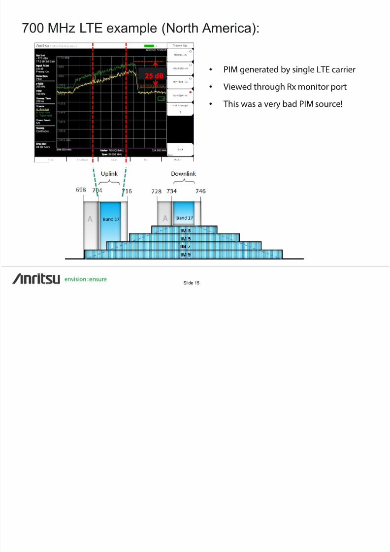
8172019 20151210 Anritsu PIM Webinar - Slides
httpslidepdfcomreaderfull20151210-anritsu-pim-webinar-slides 2434
24 Copyrightcopy ANRITSU
Digital Active DAS
Optical 1047297berdistribution
network
Digital SignalSources
POI Tray
BTS
BBUHead EndEquipment
Expansion Units
Wideband antennas
PIM
PIM
PIM
PIMSevere
LessSevere
RF Signal sourceHigh power single
band (20W)
AntennaLow power
multi band
(100mW)
LAN cabledistribution
network PIM
C-RAN
8172019 20151210 Anritsu PIM Webinar - Slides
httpslidepdfcomreaderfull20151210-anritsu-pim-webinar-slides 2534
25 Copyrightcopy ANRITSU
Distributed Radio System (DRS)
Radio Units withintegrated antenna
Expansion Unit
Base Band Unit(BBU)
Optical 1047297berdistribution
network PIM
PIM
Low power single band
(100mW)
MoreSevere
LessSevere
Low power multi band
(100mW)
PIM
LAN cabledistribution
network
PIM
8172019 20151210 Anritsu PIM Webinar - Slides
httpslidepdfcomreaderfull20151210-anritsu-pim-webinar-slides 2634
26 Copyrightcopy ANRITSU
Distributed Small Cells (DSC)
Small Cell withintegrated antenna
EthernetSwitches
Localcontroller
LAN cabledistribution
network PIM
PIM
Low power single band
(100mW)
MoreSevere
LessSevere
Core Network
Low power multi band
(100mW)
PIM
8172019 20151210 Anritsu PIM Webinar - Slides
httpslidepdfcomreaderfull20151210-anritsu-pim-webinar-slides 2734
27 Copyrightcopy ANRITSU
Is external PIM really a concern below 100 mW
bull External PIM measured while walking across office environment
bull 700 850 1900 amp 2600 MHz PIM test signals combined
bull Signi1047297cant PIM at low frequencies even with 15 dBm (32 mW) Tx power
Indoor antenna
8172019 20151210 Anritsu PIM Webinar - Slides
httpslidepdfcomreaderfull20151210-anritsu-pim-webinar-slides 2834
28 Copyrightcopy ANRITSU
How can I prevent PIM problems in IBW systems
1
Avoid frequency combinations that create low orderIM products in uplink bands
2
Use low PIM construction techniques materials
3
Avoid non-linear objects near antennas
1 and 3 above may be outside of your control
bull Multi-operator requirements
bull
Aesthetic requirements
8172019 20151210 Anritsu PIM Webinar - Slides
httpslidepdfcomreaderfull20151210-anritsu-pim-webinar-slides 2934
29 Copyrightcopy ANRITSU
Methods to mitigate external PIM1) Move the antenna
bull Non-linear objects in antenna near 1047297eld generate higher PIM
bull Moving antenna a short distance moves PIM source to far 1047297eld
bull At 20 dBm (100mW) PIM reduced gt60 dB when antenna moved 05m
Indoor antennaDiode
Near1047297eld
Far 1047297eld
8172019 20151210 Anritsu PIM Webinar - Slides
httpslidepdfcomreaderfull20151210-anritsu-pim-webinar-slides 3034
30 Copyrightcopy ANRITSU
2) Move the PIM Source
bull Electrical conduit added after DAS was
installed and commissioned
bull Safety cables lightly touching metal
surfaces on near antenna
8172019 20151210 Anritsu PIM Webinar - Slides
httpslidepdfcomreaderfull20151210-anritsu-pim-webinar-slides 3134
31 Copyrightcopy ANRITSU
3) Add attenuation between antenna amp PIM sourcePIM source
PIM source covered with Aluminum duct tape
gt40 dB PIM reduction
8172019 20151210 Anritsu PIM Webinar - Slides
httpslidepdfcomreaderfull20151210-anritsu-pim-webinar-slides 3234
32 Copyrightcopy ANRITSU
4) Direct less power at PIM source
bull Antenna with ldquonotchrdquo in horizontal pattern
bull
Rotate antenna to steer null at PIM source
bull Up to 30 dB reduction in PIM
DiodeRotate antenna
JMA Wireless
8172019 20151210 Anritsu PIM Webinar - Slides
httpslidepdfcomreaderfull20151210-anritsu-pim-webinar-slides 3334
33 Copyrightcopy ANRITSU
Summary
bull
PIM severity will be different for each IBW installation
bull
Type of construction
bull
Frequency bands in use
bull
Power levels in use
bull
PIM can be a problem even at very low power levels
bull
PIM can be mitigated by
bull
Eliminating ldquobadrdquo frequency combinations
bull
Using low PIM construction techniques materials
bull
Reducing RF energy arriving at the PIM source
8172019 20151210 Anritsu PIM Webinar - Slides
httpslidepdfcomreaderfull20151210-anritsu-pim-webinar-slides 3434
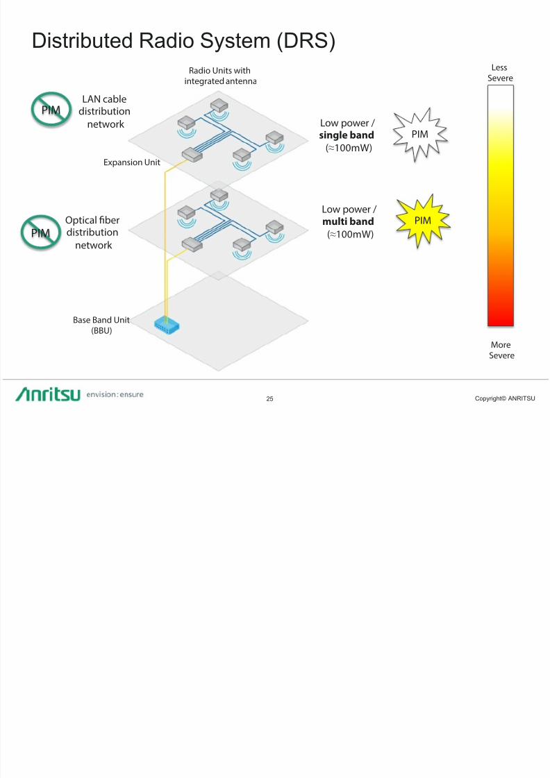
8172019 20151210 Anritsu PIM Webinar - Slides
httpslidepdfcomreaderfull20151210-anritsu-pim-webinar-slides 2734
27 Copyrightcopy ANRITSU
Is external PIM really a concern below 100 mW
bull External PIM measured while walking across office environment
bull 700 850 1900 amp 2600 MHz PIM test signals combined
bull Signi1047297cant PIM at low frequencies even with 15 dBm (32 mW) Tx power
Indoor antenna
8172019 20151210 Anritsu PIM Webinar - Slides
httpslidepdfcomreaderfull20151210-anritsu-pim-webinar-slides 2834
28 Copyrightcopy ANRITSU
How can I prevent PIM problems in IBW systems
1
Avoid frequency combinations that create low orderIM products in uplink bands
2
Use low PIM construction techniques materials
3
Avoid non-linear objects near antennas
1 and 3 above may be outside of your control
bull Multi-operator requirements
bull
Aesthetic requirements
8172019 20151210 Anritsu PIM Webinar - Slides
httpslidepdfcomreaderfull20151210-anritsu-pim-webinar-slides 2934
29 Copyrightcopy ANRITSU
Methods to mitigate external PIM1) Move the antenna
bull Non-linear objects in antenna near 1047297eld generate higher PIM
bull Moving antenna a short distance moves PIM source to far 1047297eld
bull At 20 dBm (100mW) PIM reduced gt60 dB when antenna moved 05m
Indoor antennaDiode
Near1047297eld
Far 1047297eld
8172019 20151210 Anritsu PIM Webinar - Slides
httpslidepdfcomreaderfull20151210-anritsu-pim-webinar-slides 3034
30 Copyrightcopy ANRITSU
2) Move the PIM Source
bull Electrical conduit added after DAS was
installed and commissioned
bull Safety cables lightly touching metal
surfaces on near antenna
8172019 20151210 Anritsu PIM Webinar - Slides
httpslidepdfcomreaderfull20151210-anritsu-pim-webinar-slides 3134
31 Copyrightcopy ANRITSU
3) Add attenuation between antenna amp PIM sourcePIM source
PIM source covered with Aluminum duct tape
gt40 dB PIM reduction
8172019 20151210 Anritsu PIM Webinar - Slides
httpslidepdfcomreaderfull20151210-anritsu-pim-webinar-slides 3234
32 Copyrightcopy ANRITSU
4) Direct less power at PIM source
bull Antenna with ldquonotchrdquo in horizontal pattern
bull
Rotate antenna to steer null at PIM source
bull Up to 30 dB reduction in PIM
DiodeRotate antenna
JMA Wireless
8172019 20151210 Anritsu PIM Webinar - Slides
httpslidepdfcomreaderfull20151210-anritsu-pim-webinar-slides 3334
33 Copyrightcopy ANRITSU
Summary
bull
PIM severity will be different for each IBW installation
bull
Type of construction
bull
Frequency bands in use
bull
Power levels in use
bull
PIM can be a problem even at very low power levels
bull
PIM can be mitigated by
bull
Eliminating ldquobadrdquo frequency combinations
bull
Using low PIM construction techniques materials
bull
Reducing RF energy arriving at the PIM source
8172019 20151210 Anritsu PIM Webinar - Slides
httpslidepdfcomreaderfull20151210-anritsu-pim-webinar-slides 3434
8172019 20151210 Anritsu PIM Webinar - Slides
httpslidepdfcomreaderfull20151210-anritsu-pim-webinar-slides 2834
28 Copyrightcopy ANRITSU
How can I prevent PIM problems in IBW systems
1
Avoid frequency combinations that create low orderIM products in uplink bands
2
Use low PIM construction techniques materials
3
Avoid non-linear objects near antennas
1 and 3 above may be outside of your control
bull Multi-operator requirements
bull
Aesthetic requirements
8172019 20151210 Anritsu PIM Webinar - Slides
httpslidepdfcomreaderfull20151210-anritsu-pim-webinar-slides 2934
29 Copyrightcopy ANRITSU
Methods to mitigate external PIM1) Move the antenna
bull Non-linear objects in antenna near 1047297eld generate higher PIM
bull Moving antenna a short distance moves PIM source to far 1047297eld
bull At 20 dBm (100mW) PIM reduced gt60 dB when antenna moved 05m
Indoor antennaDiode
Near1047297eld
Far 1047297eld
8172019 20151210 Anritsu PIM Webinar - Slides
httpslidepdfcomreaderfull20151210-anritsu-pim-webinar-slides 3034
30 Copyrightcopy ANRITSU
2) Move the PIM Source
bull Electrical conduit added after DAS was
installed and commissioned
bull Safety cables lightly touching metal
surfaces on near antenna
8172019 20151210 Anritsu PIM Webinar - Slides
httpslidepdfcomreaderfull20151210-anritsu-pim-webinar-slides 3134
31 Copyrightcopy ANRITSU
3) Add attenuation between antenna amp PIM sourcePIM source
PIM source covered with Aluminum duct tape
gt40 dB PIM reduction
8172019 20151210 Anritsu PIM Webinar - Slides
httpslidepdfcomreaderfull20151210-anritsu-pim-webinar-slides 3234
32 Copyrightcopy ANRITSU
4) Direct less power at PIM source
bull Antenna with ldquonotchrdquo in horizontal pattern
bull
Rotate antenna to steer null at PIM source
bull Up to 30 dB reduction in PIM
DiodeRotate antenna
JMA Wireless
8172019 20151210 Anritsu PIM Webinar - Slides
httpslidepdfcomreaderfull20151210-anritsu-pim-webinar-slides 3334
33 Copyrightcopy ANRITSU
Summary
bull
PIM severity will be different for each IBW installation
bull
Type of construction
bull
Frequency bands in use
bull
Power levels in use
bull
PIM can be a problem even at very low power levels
bull
PIM can be mitigated by
bull
Eliminating ldquobadrdquo frequency combinations
bull
Using low PIM construction techniques materials
bull
Reducing RF energy arriving at the PIM source
8172019 20151210 Anritsu PIM Webinar - Slides
httpslidepdfcomreaderfull20151210-anritsu-pim-webinar-slides 3434

8172019 20151210 Anritsu PIM Webinar - Slides
httpslidepdfcomreaderfull20151210-anritsu-pim-webinar-slides 3134
31 Copyrightcopy ANRITSU
3) Add attenuation between antenna amp PIM sourcePIM source
PIM source covered with Aluminum duct tape
gt40 dB PIM reduction
8172019 20151210 Anritsu PIM Webinar - Slides
httpslidepdfcomreaderfull20151210-anritsu-pim-webinar-slides 3234
32 Copyrightcopy ANRITSU
4) Direct less power at PIM source
bull Antenna with ldquonotchrdquo in horizontal pattern
bull
Rotate antenna to steer null at PIM source
bull Up to 30 dB reduction in PIM
DiodeRotate antenna
JMA Wireless
8172019 20151210 Anritsu PIM Webinar - Slides
httpslidepdfcomreaderfull20151210-anritsu-pim-webinar-slides 3334
33 Copyrightcopy ANRITSU
Summary
bull
PIM severity will be different for each IBW installation
bull
Type of construction
bull
Frequency bands in use
bull
Power levels in use
bull
PIM can be a problem even at very low power levels
bull
PIM can be mitigated by
bull
Eliminating ldquobadrdquo frequency combinations
bull
Using low PIM construction techniques materials
bull
Reducing RF energy arriving at the PIM source
8172019 20151210 Anritsu PIM Webinar - Slides
httpslidepdfcomreaderfull20151210-anritsu-pim-webinar-slides 3434
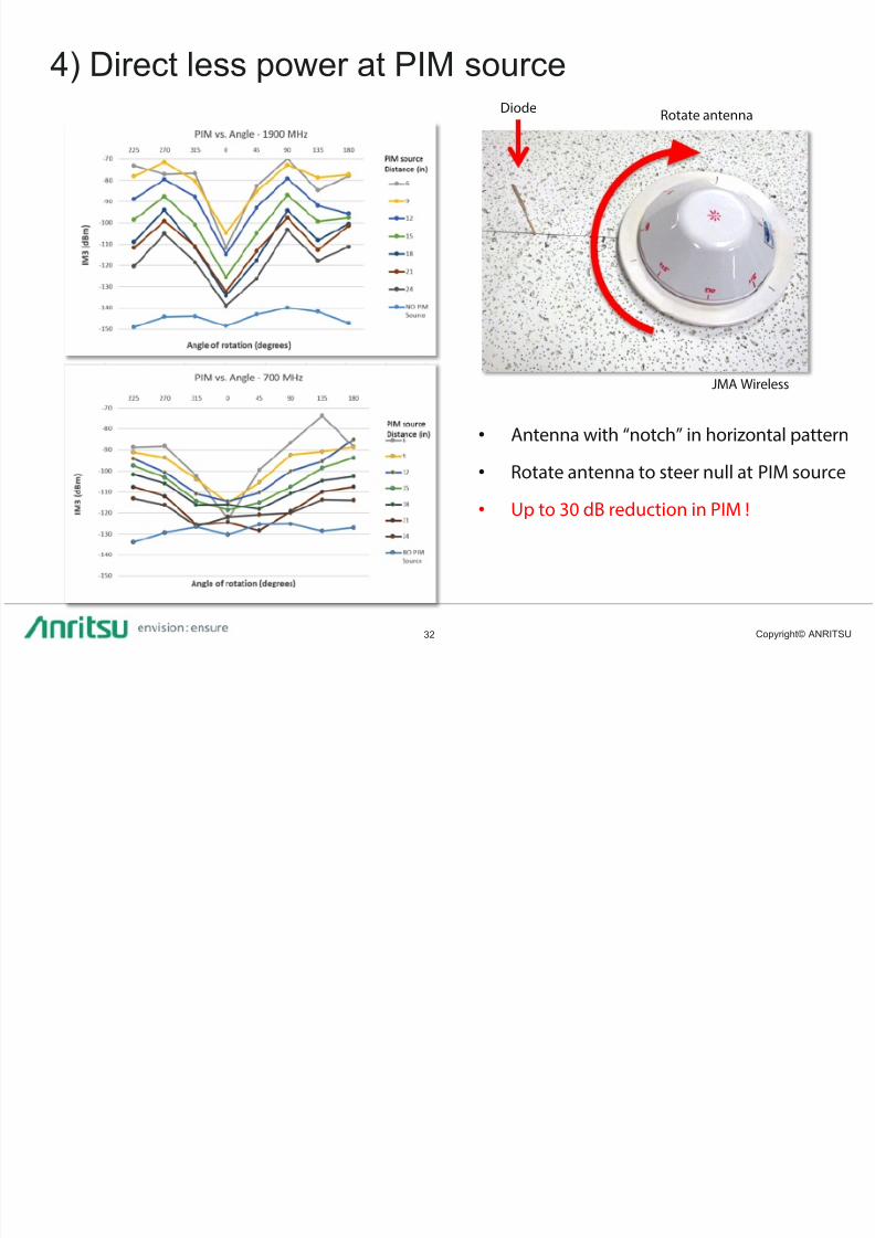
8172019 20151210 Anritsu PIM Webinar - Slides
httpslidepdfcomreaderfull20151210-anritsu-pim-webinar-slides 3434