2015 © the authors, some rights reserved; morphogenesis ... · morphogenesis and...
TRANSCRIPT

2015 © The Authors, some rights reserved;
R E S EARCH ART I C L E
MATER IALS ENG INEER ING
nsee American Association forment of Science. Distributed
tive Commons Attribution
cial License 4.0 (CC BY-NC).
dv.1400052
Morphogenesis and mechanostabilization ofcomplex natural and 3D printed shapesChandra Sekhar Tiwary,1,2* Sharan Kishore,1 Suman Sarkar,1 Debiprosad Roy Mahapatra,3
Pulickel M. Ajayan,2 Kamanio Chattopadhyay1
exclusive lice
the Advance
under a Crea
NonCommer
10.1126/scia
Dow
nloaded
The natural selection and the evolutionary optimization of complex shapes in nature are closely related to theirfunctions. Mechanostabilization of shape of biological structure via morphogenesis has several beautiful ex-amples. With the help of simple mechanics-based modeling and experiments, we show an important causalitybetween natural shape selection as evolutionary outcome and the mechanostabilization of seashells. The effectof biological growth on the mechanostabilization process is identified with examples of two natural shapes ofseashells, one having a diametrically converging localization of stresses and the other having a helicoidally con-centric localization of stresses. We demonstrate how the evolved shape enables predictable protection of softbody parts of the species. The effect of bioavailability of natural material is found to be a secondary factor com-pared to shape selectivity, where material microstructure only acts as a constraint to evolutionary optimization.This is confirmed by comparing themechanostabilization behavior of three-dimensionally printed synthetic poly-mer structural shapes with that of natural seashells consisting of ceramic and protein. This study also highlightsinteresting possibilities in achieving a new design of structures made of ordinary materials which have bio-inspired optimization objectives.
hfrom
on July 8, 2020ttp://advances.sciencemag.org/
INTRODUCTION
Understanding biological structures toward nature-inspired design isan important field of research (1–5). Over the past several decades,numerous studies had been carried out to identify the scientific basisfor the naturally adaptive growth of biological structures through en-vironmental exposure of biomaterials and continuous optimization ofthe response of these biomaterials at various geometric length scalesto satisfy specific environmental conditions (2, 6–11). A significantadvancement has been made in recent years in this field of science,and it has led to important applications in defense and safety, auto-motive, and architecture (9–11). Several groups of researchers havereported detailed reviews summarizing these advancements (2, 6–12).Most biological materials consist of fascinating structure atmicron andsubmicron scales (2, 6–17). Examples are the organization of nanoscalecollagen fibrils in extracellularmatrix structures, the two-level hierarchyof open cell structure in falcon feather, andmanymore (12–17). A seriesof interesting studies on the nacre shell has been reported. Nacre shellshave a unique microstructure consisting of CaCO3 with organic mole-cules (13–21). Such kind of microstructure gives rise to enhanced me-chanical properties including great strength with low mass density andgreat toughness (8, 21). This type of microstructure has been success-fully incorporated in materials for defense and structural applications(2, 6–17). Biological structures naturally evolve into large macroscopicstructures, and understanding of the underlying causality is challengingand of great importance. These natural macroscopic shapes are verydifferent from the most common shapes (such as sphere, cylinder, andpolyhedron) that we use in our engineering designs. The level of com-plexity in these biological structures clearly depends on the environ-
1Department of Materials Engineering, Indian Institute of Science, Bangalore, Karnataka560012, India. 2Department of Materials Science and Nanoengineering, Rice University,Houston, TX 77005, USA. 3Department of Aerospace Engineering, Indian Institute ofScience, Bangalore, Karnataka 560012, India.*Corresponding author. E-mail: [email protected]
Tiwary et al. Sci. Adv. 2015;1:e1400052 15 May 2015
mental conditions under which they evolve and adapt via continuousoptimization. Clearly, there is hardly any direct sensory pathway inmost of these biological structures to aid such adaptation; however,an evolutionary biological process follows. This paper is primarilyconcerned with the scheme of causality that drives natural biologicalevolution rather than the evolution process itself. To the best of ourknowledge, the reason behind the macroscopic shape of the nacre shellremains unknown, and the complexity of such a shape is significantcompared to the families of natural biological structures. How theenvironmental conditions alter and ultimately improve the mechanicalresponse of the structure as the nacre shell grows is important, but yetto be analyzed. We assume that the metabolic process to accumulatebiomass invariably favors the specific environmental conditions invol-ving food and other essential supplies, besides favoring the primaryfactor, that is, the mechanical stimulation as in the case of nacre shell.Subsequent to this important aspect of the study, we further apply shapeselection–related advantages in artificially engineered structural mate-rial and explore the possibility of creating stronger structures out of or-dinary materials and comparing the behavior of these engineeredstructures with that of the natural biological structures. The engineeredstructures are manufactured by the three-dimensional (3D) printing ofcommonly used polymers. Future exploration to engineer these struc-tures via a synthetic biology route may be of considerable interest tothe scientific community.
Detailed studies involving experiments and simulations have ex-plained the importance of the shapes of bones, beak shell, ladybug legs,kingfisher beak, boxfish, shark teeth, and many more (2, 6–17). Theunique mechanical response of these relatively simple shapes has at-tracted major attention from the engineering community. These shapesand the associated mechanical concepts have been applied to protectiveshields, automotive parts, and building architectures (2, 6–17).
The evolutionary optimization of shape is one of the key approachesthat natural species adopt for survival under varied environmental con-ditions such as changing mechanical load (8, 18–21). Morphogenesis via
1 of 9

R E S EARCH ART I C L E
on July 8, 2020http://advances.sciencem
ag.org/D
ownloaded from
natural selection creates complex shapes that are important for variousfunctions and adaptation. For example, shape engineering can providenovel architectures that help in damping high-impact collisions andprotect objects or living species inside (1–11, 15–21). However, a clearunderstanding of the mechanical response of the naturally occurringcomplex shapes with respect to its evolutionary path is still lacking.Here, we have considered seashell, which is found abundantly nearseashores, as an example of complex but fascinating shapes. There isa specific causality of such shapes in protecting the species inside theshell (22, 23), and this poses an interesting problem to be addressed.The shape of seashells has attracted attention among mathematicians,artists, and biologists (11, 24–27). Here, we have chosen two differentshapes, namely, shell-1, which has a moon shape, also known as patel-liform or bivalves, and shell-2, which has a screw shape that is famouslyknown as Turritella or turbinate. Both these shells house a species ofmollusks or snails. The samples are collected from the seashore ofPondicherry in the southern part of India. Various details of theseseashells from the perspective of structural and materials engineeringare given in figs. S1 to S5. The material composition and mechanicalproperties of various seashells have been characterized (8, 21). Depend-ing on the growth and environmental conditions such as the levels ofsalt and other elements in seawater and age, the fractions of CaCO3 andorganic compounds change, ultimately giving rise to various patternsof layers at nano- and microscales (8, 11, 18–26). The changes in thepatterns and compositions give rise to different mechanical properties(8, 21). However, mechanical property variations due to these factorsare probably not that significant among similar subspecies of seashellsfound in different parts of the world, and are hence a secondary effectas compared to shape selectivity, which is a primary factor in the shellstructure’s response to mechanical load.
A detailed mechanical response of shell-1 subjected to underwaterpressure is simulated and analyzed using the 3D finite element meth-od (FEM). Subsequently, we grow synthetic polymer materials usingthe 3D printing method to realize an identical structural shape ofshell-1. This is carried out to verify whether the material compositionwithin the structural shape is the primary factor that controls the me-chanical response or if the structural shape itself is the primary evolu-tionary outcome. Furthermore, 3D printing is adopted for creating thisshape to explore new avenues in manufacturing bio-inspired structuralshapes. Next, the analytical and synthesis approach explained above isapplied to a more complexly shaped shell, shell-2. Shell-2 shows en-hancement in its mechanical response that leads to better survivabilityunder greater mechanical loads compared to that of shell-1. Such anevolutionary adaptation to enhance mechanical response by increasingthe complexity of shape and the underlying causality is explained in thispaper with the help of an analytical mechanics model.
The microstructural details of various regions of the seashells areanalyzed using scanning electron microscopy (SEM), x-ray diffraction(XRD), and electron probe microanalysis (EPMA), and the results areshown in figs. S1 and S2. The microstructures of all these regions arefound to be similar on the top surface, whereas the bottom surface isnormally flat and does not reveal any pattern. Electronmicroscopy con-firms the absence of microstructural inhomogeneity across the samplesexcept for thickness gradation. Chemical composition analysis at vari-ous locations of the shell shows the presence of calcium (Ca), carbon(C), and oxygen (O) without appreciable variation in the composition.EPMA indicates the presence of Ca-based oxides (Ca, 54 ± 5 atomic%;C,36±8 atomic %; O, 21±10 atomic %) (see the Supplementary Materials).
Tiwary et al. Sci. Adv. 2015;1:e1400052 15 May 2015
XRD peaks measured at different regions indicate the presence of or-thorhombic CaCO3 (SupplementaryMaterials). The conclusion basedon these results is that material microstructure and inhomogeneity areless likely to contribute to the evolutionarymechanism toward the me-chanical response of these seashells. These factors, however, can act asconstraints on the evolutionary process. Hence, mechanical stress in thematerial microstructure must ultimately be the common link betweenstructural shape and biological growth. We analyzed the mechanical de-formation of thesemicrostructures usingmicrohardness tests with smallloads (~50 g). The details of these tests are described in Methods.Hardness at various locations on the surface of shell-1 is in the rangeof 250 ± 20 HV (Vickers pyramid number) (fig. S4).
The organisms associated with the seashells grow in deep waterand hence the shells are subjected to amuch higher pressure comparedto the atmospheric pressure. Protection of the organism’s soft bodyparts by its outer hard shell is a primary requirement (8, 11, 18–29).There are also other biological adaptation requirements to achieve lo-comotion: sensory functions, food intake, and survival (see fig. S5). Criticalparts of the body, therefore, have to grow under such conflicting require-ments. Shell-1 has a diametrically converging localization (defined infig. S5), which is an optimal region for the growth of soft and locomotiveparts of the body. To understand the reason behind such preferential lo-calization for protection of the soft body parts and the overall effect itimposes on the shape, we compare the deformation behavior of shell-1and shell-2. 3D FEM is used to simulate the deformation behaviors.We first analyze the significance of the shape of shell-1. As shown in
A
B
Side view Side view Top view
Fig. 1. The natural shells. (A and B) Digital images of (A) shell-1 and (B)shell-2 taken in their natural form at different projections. On the basis of the
actual dimension, computer-generated shapes are created and 3D printed.2 of 9

R E S EARCH ART I C L E
on July 8, 2020http://advances.sciencem
ag.org/D
ownloaded from
Fig. 1A, there are two distinct features of shell-1 compared to a nor-mal hemispherical shape. One of these corresponds to convergingdiametric localization toward the periphery, and the other is a systemof periodic channels or grooves on the surface (see fig. S5). To clearlyunderstand the importance of these two features in shell-1, we took ahemispherical shell, which is the simplest of all shapes, and com-pared it with a shell with converging diametric localization but withoutany groove on its surface, thus introducing a slightly higher complexity.Figure 2 (A to C), shows the finite element mesh (shown as inset) andthe vonMises stress distribution on the surface of these structures withincreased complexities. Figure 2A shows a symmetric stress distribu-tion pattern for the hemispheric shape about itsmajor andminor axes,whereas Fig. 2 (B and C), shows an azimuth symmetric but localizedstress concentration pattern consistent with the diametric localizationand center line between each pair of grooves of shell-1. Figure 2C showshigher stress and a nonuniform distribution (no directional preference)compared to that inFig. 2B (stress is distributedor guidedby the grooves).The minimum and maximum stresses observed are also greater forshell-1 (Fig. 2C) in comparison to the other two simpler shapes in Fig. 2(A and B). That is, for a particular magnitude of pressure applied onthese structures having increasing complexity (shell-1), certain regionsremain under lower stress while a higher state of stress evolves in suit-able and desirable locations. Ultimately, themicrostructuremust sustainsuch stress a concentration, and in the event of failure, it would still al-low the soft body parts to survive in the least stressed region. One of themost widely used shapes in today’s structural engineering designs is thehemispherical one, which acts as a good load-transferring shape that eas-ily transfers the applied load to its base structure on the edge. Althoughthis is quite expected, what is not obvious is the reason behind the shellchanging its shape from a hemispherical one to that with a diametricallylocalized or shrinking cross section. We hypothesize that the geometriclocalization evolves to distribute the external load suitably on the cir-cumferential edge and more toward the diametrically localized region,thereby safeguarding the core cavity region and opening up the circum-ferential edge region for other biological needs. Details are marked in avertical section of the shape shown in Fig. 2A. With further complexityintroduced through the incorporation of the grooves, the stress gradientis further distributed or channelized in a directionally preferredmannerin shell-1. The grooves help in the directional transfer of stress by dis-tributing the stress over alternate concave and convex grooves (see fig.S5). The stress distribution across the grooves is shown in a vertical sec-tion of the shell (Fig. 2C).
Figure 2D indicates an increase in the maximum stress level aswell as in the minimum stress level with increasing complexity ofshape leading to shell-1 when its thickness is small (~0.5 mm asshown in Fig. 2E). The rise in maximum stress level due to increasingcomplexity confirms the evolutionary outcome that the stress-inducedfracture of the shell-1 is localized at regions away from where the softpart of the body survives. Figure 2E shows the adaptation of shell-1 tostress levels as it grows and as the thickness of the shell increases. Withan optimal thickness of ~1 mm, shell-1 reduces the magnitude of stresslevels at the circumferential edge to enable easy locomotion that governsthe evolutionary optimization needs. A more detailed mechanistic ex-planation of this phenomenon will be given later.
As described in previous studies (30–35), the thickness of the shellvaries, depending on the age of mollusks (species that grows with shell-1as its outer body). The thickness of the shell is a result of the internalgrowth of biominerals and proteins, controlled by the tissues under-
Tiwary et al. Sci. Adv. 2015;1:e1400052 15 May 2015
neath the hard shell and by external pressure, temperature, pH, etc. Tobetter understand growth in terms of thickness to improve the stressdistribution, we have simulated the stress distribution of shell-1 withincreasing thickness and under a pressure of 0.1 bar, as shown in Fig.2E. The stress level quickly saturates as the shell thickness increasesbeyond ~1 mm in the present samples of shell-1. For ~1-mm thicknessof shell-1, the difference between the maximum and the minimumstresses is also greater compared to that for the other greater thicknesses.Figure 2C also shows the maximum stress being distributed along theconvex ridges confined by two successive channels. Compared to thestress distribution shown in Fig. 2 (A and B), this type of directionalstress transfer via alternate distribution of maximum and minimumstresses ultimately provides a greater stress-carrying capacity with lo-calized failure rather than a complete collapse of the shape. This regi-men of stress (~15 to l20 m of sea depth) and thickness (~1 mm)resembles that of the morphology of most natural seashells. The spe-cies living inside the shell biologically regulates the shell thickness, aprocess encoded in the cellular pathway of that species to achieve op-timum protection. The protection requirement reduces as the speciesgrows further, and hence the shell thickness saturates, explaining whythe larger thicknesses are not typically found among these seashells.
As explained earlier, the diametrically converging or shrinking re-gion holds the two halves of the shell together under the externally ap-plied pressure under water, whereas the rest of the circumferential edgedividing the two halves can easily open and close (see fig. S5). The corecavity hosting the living species is not supposed to be subjected to enor-mous pressure. To demonstrate this on a scientific basis, we show asimple simulation in Fig. 2 (F and H). The simulation idealizes the loadtransfer from one-half of the shell to its circumferential edge held rig-idly. This condition is simulated by considering a flat aluminum blockas the rigid base. We plot the stress pattern induced on an aluminumblock placed at the bottom of the shell. The three shells with a geometryof increasing complexity transfer the stress from their top plateau regionto the circumferential edge region. The stress pattern on the hemispher-ical shape is symmetrical, and greater stress accumulates circumferen-tially, covering most of the bottom contact surface of the plate. Thisleads to a greater chance of damaging a weaker material base if attachedto the bottom. The shell with only the diametrically converging shape butwithout the grooves actually concentrates greater stress at three distinctregions circumferentially at the base, thus leaving a greater area with low-er stress in the base material. Finally, the natural shape of shell-1 enableseven a small region to have high stress, which occurs precisely at the dia-metric localization region on the circumference. As a result, a much lessstress is experienced in the central cavity region, and hence the living spe-cies at this location is safer compared to those in other shapes.
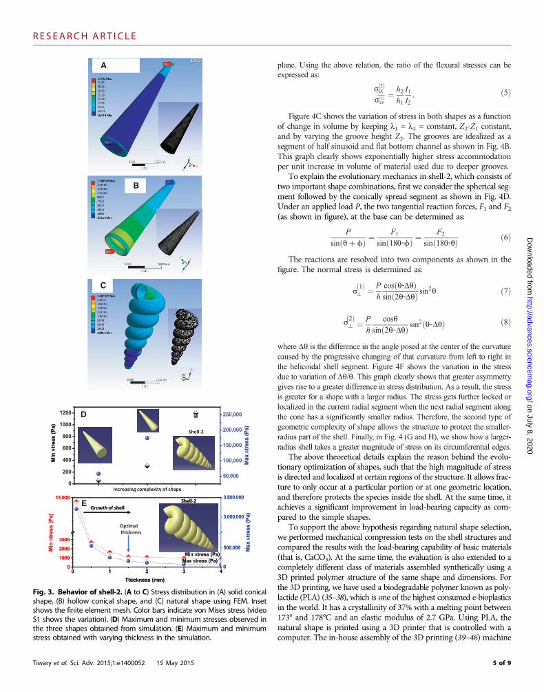
For the second type of shell with helical morphology (shell-2), thehelicoidally concentric end is supposed to provide protection to thesoft body parts of the species. We have compared the stress distribu-tion with its counterpart geometries which have simple shapes, thatis, a solid cone, and then an intermediate complex shape with a hol-low cone structure with similar variation of diameter as shown in Fig. 3.The solid cone in Fig. 3A shows less variation in stress pattern rela-tive to that of a hollow cone (Fig. 3B). The stress distribution in shell-2 shows a totally different behavior compared to that in the solid andhollow cones, as shown in Fig. 3C. It clearly localizes the stress pre-dominantly on the first ring, and the rest of the rings remain more orless unstressed. A cut section of shell-2 is shown in Fig. 5H that re-veals greater stress is taken by the inner helicoidal surface. Hence, this
3 of 9

R E S EARCH ART I C L E
Tiwary et al. Sci. Adv. 2015;1:e1400052 15 May 2015
on July 8, 2020http://advances.sciencem
ag.org/D
ownloaded from
becomes more efficient in protecting the outersurface against high stress as compared to thesimpler shapes shown in Fig. 3 (A and B). Themaximum and minimum stresses are plotted inFig. 3D. The results suggest that the naturalshape of shell-2 distributes greater stress fromthe outer wall to the inner core wall, which isnot possible in the other two simpler shapes.This is because of the continuously changing di-ametrical turns and the helicoidal surfaces ofshell-2.
To understand the role of shell thickness instress distribution in the case of shell-2 similarto what we have analyzed for shell-1, we haveperformed simulation with varying thickness.Figure 3E shows the optimal growth of thick-ness that is required to reduce the differencein maximum and minimum stress levels. InFig. 3E, we observe that for thicknesses greaterthan ~1.5 mm, the stress levels tend to saturate,and so is the extent of stress transfer from the out-er surface to the inner core of the helicoidalturns. Hence, natural shape selection goes handin hand with thickness selectivity as the shellgrows thicker.
A mechanics-based predictive model is usedto explain the relationship between stress trans-fer path and shape and thickness selectivity, andto provide further scientific insight on naturalshape selection as an evolutionary tool of en-hanced survival. First, a simplified elementalsegment of shell-1 is considered in comparisonwith a simple hemispherical shell as shown inFig. 4 (A and B). The flexural stress in the simpleshell segment is denoted as sxx
ð1Þ and that inshell-1 with grooves is denoted as sxx
ð2Þ,
sxxð1Þ ¼ h1
2M
I1ð1Þ
sxxð2Þ ¼ h2
2M
I2ð2Þ
where M is the applied bending moment as afunction of pressure, h1 and h2 are the thicknessof the simple shell and shell-1, respectively, andI1 and I2 are the second area moments expressed as:
I1 ¼ 1
12lh31 ð3Þ
I2 ¼ ∫z¼0
z¼h2
z2dA ð4Þ
Here, l is the segment length, and z is the thick-ness coordinates measured normal to a reference
Top view
Top view
Top view
Al block
Al block
Al block
Fig. 2. Behavior of shell-1. (A toC) Stress distribution in (A) hemispherical shape, (B) shapewithoutgrooves, and (C) shapewith grooves simulated using FEM. Insets show the finite elementmesh. Edges
are constrained. Color bars indicate vonMises stress (video S1 shows the variation). A vertical sectionacross a line (1–2) is shown with stress distribution. (D) Maximum and minimum stresses in the threeshapes obtained from simulation. (E) Maximum andminimum stresses obtainedwith varying thick-ness in the simulation. (F toH) Stress distribution obtained fromsimulationwith the three shapes kepton aluminum substrate. Insets show the stress distribution on the bottom surface of the substrate, withcolor bar showing von Mises stress (video S1 shows the variation).4 of 9
R E S EARCH ART I C L E
Tiwary et al. Sci. Adv. 2015;1:e1400052 15 May 2015
on July 8, 2020http://advances.sciencem
ag.org/D
ownloaded from
plane. Using the above relation, the ratio of the flexural stresses can beexpressed as:
sxxð2Þ
sxxð1Þ ¼
h2h1
I1I2: ð5Þ
Figure 4C shows the variation of stress in both shapes as a functionof change in volume by keeping l1 = l2 = constant, Z2-Z1 constant,and by varying the groove height Z2. The grooves are idealized as asegment of half sinusoid and flat bottom channel as shown in Fig. 4B.This graph clearly shows exponentially higher stress accommodationper unit increase in volume of material used due to deeper grooves.
To explain the evolutionary mechanics in shell-2, which consists oftwo important shape combinations, first we consider the spherical seg-ment followed by the conically spread segment as shown in Fig. 4D.Under an applied load P, the two tangential reaction forces, F1 and F2(as shown in figure), at the base can be determined as:
P
sinðqþ ϕÞ ¼F1
sinð180‐ϕÞ ¼F2
sinð180‐qÞ ð6Þ
The reactions are resolved into two components as shown in thefigure. The normal stress is determined as:
s⊥ð1Þ ¼ P
h
cosðq‐DqÞsinð2q‐DqÞ sin
2q ð7Þ
s⊥ð2Þ ¼ P
h
cosqsinð2q‐DqÞ sin
2 q‐Dqð Þ ð8Þ
where Dq is the difference in the angle posed at the center of the curvaturecaused by the progressive changing of that curvature from left to right inthe helicoidal shell segment. Figure 4F shows the variation in the stressdue to variation of Dq/q. This graph clearly shows that greater asymmetrygives rise to a greater difference in stress distribution. As a result, the stressis greater for a shape with a larger radius. The stress gets further locked orlocalized in the current radial segment when the next radial segment alongthe cone has a significantly smaller radius. Therefore, the second type ofgeometric complexity of shape allows the structure to protect the smaller-radius part of the shell. Finally, in Fig. 4 (G and H), we show how a larger-radius shell takes a greater magnitude of stress on its circumferential edges.
The above theoretical details explain the reason behind the evolu-tionary optimization of shapes, such that the high magnitude of stressis directed and localized at certain regions of the structure. It allows frac-ture to only occur at a particular portion or at one geometric location,and therefore protects the species inside the shell. At the same time, itachieves a significant improvement in load-bearing capacity as com-pared to the simple shapes.
To support the above hypothesis regarding natural shape selection,we performed mechanical compression tests on the shell structures andcompared the results with the load-bearing capability of basic materials(that is, CaCO3). At the same time, the evaluation is also extended to acompletely different class of materials assembled synthetically using a3D printed polymer structure of the same shape and dimensions. Forthe 3D printing, we have used a biodegradable polymer known as poly-lactide (PLA) (35–38), which is one of the highest consumed e-bioplasticsin the world. It has a crystallinity of 37% with a melting point between173° and 178°C and an elastic modulus of 2.7 GPa. Using PLA, thenatural shape is printed using a 3D printer that is controlled with acomputer. The in-house assembly of the 3D printing (39–46) machine
A
B
C
D
E
Fig. 3. Behavior of shell-2. (A to C) Stress distribution in (A) solid conicalshape, (B) hollow conical shape, and (C) natural shape using FEM. Inset
shows the finite element mesh. Color bars indicate von Mises stress (videoS1 shows the variation). (D) Maximum and minimum stresses observed inthe three shapes obtained from simulation. (E) Maximum and minimumstress obtained with varying thickness in the simulation.5 of 9

R E S EARCH ART I C L E
on July 8, 2020http://advances.sciencem
ag.org/D
ownloaded from
uses a heater to melt the PLA, and prints are shown in video S1. Fur-ther details about the process are described in Methods.
Figure 5 shows the compression test results comparing the stress-carrying capacity of the natural shapes as compared to that of simpleshapes for both natural structures and the artificially created structuralshapes by 3D printing. Figure 5 (A and B), shows the compressive loadversus elongation plots for the natural and the 3D printed shell-1. Firstof all, the natural shell-1 and shell-2 in Fig. 5 (A and C), have sustaineda load of 250 and 130 N, respectively (for the given area under com-pression test). For the similar contact area as compared to shell-1 andshell-2, CaCO3 ceramic can take a maximum of 130- and 70-N loads,respectively. The loads are calculated using the yield strength of stan-dard CaCO3 in standard cylindrical shape multiplied by the respectivecontact areas for shell-1 and shell-2. These results show that thecomplex shapes can sustain loads that are nearly twice as high as theirbasic material constituent and their respective counterpart simpleshapes. The load versus elongation curve for the 3D printed PLA shell-1 and shell-2 shows a maximum load of 360 and 550 N, which are near-ly three and five times higher, respectively, than that of a 6-mm-diameterwire made of PLA. This effect is due to compression of the verticalregion (short column) of the curved segments in shell-1 and shell-2, whereinPLA first undergoes hardening (increasing slope of load-deformationcurve), followed by transverse shear failure at the contact region, whichis unlike brittle fracture without any hardening in natural ceramic.The above observation further confirms our hypothesis of the high
Tiwary et al. Sci. Adv. 2015;1:e1400052 15 May 2015
stress-carrying capacity of these complex shapes, whereas the availabilityof natural materials acts as an evolutionary constraint in the naturalshells. This can be an interesting tool for bio-inspired design via a syn-thetic biology route. Compared to the natural shell, the 3D printed poly-mer shows even better enhancement of overall load-carrying capacitydue to geometrically induced material hardening as compared to ce-ramic. The effect of layer-by-layer deposition of polymer as comparedto that of ceramic may have a role in microstructure, deformation, andfailure behavior. To understand the protection mechanism offered bythe complex shapes, the fracture behaviors of the natural and 3D printedshells are compared with our simulated results. Figure 5E shows thestress concentration at the left edge of simulated shell-1, which is similarto the results obtained in the compression tests of the natural shell-1 aswell as the 3D printed shell-1. Figure 5H shows the simulated stressbands oriented at an angle of about 45°. The compression test results alsoshow a similar 45° angle crack in the natural shell-2 as well as in the 3Dprinted shell-2.
In conclusion, we have explored the mechanical reasons behind thenatural choice of particular size and shape in natural seashells. The 3DFEM analysis followed by a simplified analytical solution reveals theeffect of such morphogenesis in terms of stress distribution. Ouranalyses show how the complex shape selection prefers spatial ar-rangement of soft body parts for protection under increasingly intenseunderwater pressure while at the same time enabling efficient locomo-tion and other biological interaction with the external ecosystem.
A
C
B
D
F H
E
G
Fig. 4. Role of shape under loading. (A) A flat segment of large-diameter simple shape. (B) Approximated shape of a periodic segment of the cir-cumferential edge of shell-1. (C) Relative change in the maximum bending stress analytically estimated for the approximated segment versus relative
change in the material volume for increasing complexity in the shape of shell-1. (D and E) Free-body diagrams of a simplified segment of simple shape ofa shell of constant radius (D) and simplified diagram of shell-2 (E). (F) Relative change in the maximum bending stress versus relative difference in theEuler angle obtained analytically. (G) Free-body diagram showing internal forces in tangential direction acting on various helicoidal segments sliced alongthe major axis of shell-2. (H) Ratio of load transferred on segment end and the applied transverse load (|F|/|P|) in shell-2 with varying Euler angles. rindicates the radius of curvature of the segments.6 of 9

R E S EARCH ART I C L E
Tiwary et al. Sci. Adv. 2015;1:e1400052 15 May 2015
Dow
nloaded fr
Mechanical testing using natural as well as 3D printedshapes further confirms this. We used PLA-based3D printed polymer biomimetic structures thathave shown even further improvements in themechanical load–carrying capacity as comparedto the natural composite made of biomaterials andprotein. The study could provide new approaches todeveloping structural components with complexshapes bymimickingnatural shapes thathave evolvedto provide mechanostabilization in living species.
Finally, we present a mechanics-based modelto explain the evolution of two complex shapesin shells as they grow in nature. Such complexshapes play a crucial role in stress transfer andin enhancing the safety of the living species resid-ing inside from extreme conditions. Using thisunderstanding, we have fabricated similar shapes,using synthetic materials with the help of 3Dprinting, that yield superior properties as com-pared to the conventional shapes. The presentstudy opens up pathways for designing newarchitecture for structural applications.
on July 8, 2020http://advances.sciencem
ag.org/om
METHODS
Simulation detailsPrecise dimensional measurements of shape wereperformed using a Vernier caliper, whereas that ofsurface patterns were done using SEM. Usingthese measured values, the two shells were drawnin Catia V5 (the generative shape design module).
Modeling of shell-1. A number of planeswere drawn with respect to a reference plane atdifferent angles. In each of these, curved lines weredrawn, all originating from a single point. The ra-dius of the curvature varied in each plane so as toget an approximate model of the naturallyoccurring shell. After all the lines were generated,a surface was generated over all the lines, so thatthey appear similar to the natural shell.
Modeling of shell-2. A cone was generated,and on the surface of the cone, a helix of variablepitch and number of revolutions was generated.The cone was then suppressed, and only the con-ical helix was made to be visible. After this, a circlesketch was generated at the beginning of the con-ical helix. An adaptive sweep tool was used tosweep the circle at various diameters and the con-ical helix as the guide curve, thereby generatingthe approximate model of natural shell.
The modeled shell was then analyzed in Ansys14 workbench. The module used was static struc-tural for all the simulations. In all the simulations,a pressure of 10,000 Pa was applied on the surfaceof the shell. The von Mises yield criterion wasused to analyze all the simulations. Simulations
A
C D
B
E
H
F
G
I J
Fig. 5. Experiment and simulation. (A and B) Load versus strain plot for natural and 3D printedshell-1. (C and D) Load versus strain plot for natural and 3D printed shell-2. Digital image of
the experimental setup of uniaxial compression testing (inset). (E) Stress distribution in shell-1.(F and G) Digital images of natural and 3D printed shells. (H) Stress distribution in shell-2.(I and J) Digital images of natural and 3D printed shell-2.7 of 9

R E S EARCH ART I C L E
http://advances.sciencemag.or
Dow
nloaded from
were also done by varying the thickness of the shell. The materialproperties for the shell were user-defined with an elastic modulus of70 GPa and a Poisson’s ratio of 0.33. For the experiments involvingthe plate, from the general material library in Ansys 14. The edgeswere fixed, and the pressure was applied perpendicular to all pointson the curved part of the shell. A compression test was performed toverify the FEM results. The conditions of the compression setup mustbe similar to the simulation setup. Therefore, boundary conditionswere chosen such that they are the closest approximation to the com-pression setup.
Experimental detailsThe natural shells were washed with water and cleansed before anal-ysis. An environmental SEM (FEI) with a lower voltage of 5 to 15 kVwas used for microstructural analyses. The composition was measuredusing a field emission gun–electron probe microanalyzer (JEOL). TheXRD was performed on a Cu Ka target using X-Pert Pro. The hard-ness measurement of shell-1 and shell-2 was performed using a CSMindenter under a load of 50 g. The hardness machine was calibratedusing standard samples.
The modeled shell was then subjected to 3D printing, which uses a3-mm-diameter rope PLA polymer as the stock. The heater wasattached to a nozzle of 300-mm diameter. The brass nozzle was heatedat 200°C for printing. The 3D axis of the nozzle is controlled usingcomputer-controlled step motors. The computed design was printedlayer by layer as shown in video S1. The natural as well as 3D printedshells were subjected to compression tests at a strain rate of 10−3/s usinga Dartec servo-hydraulic machine. A layer of cello tape was wrappedaround the sample to prevent the spreading of the broken pieces andalso to view the cracks easily. The broken pieces of the natural shellwere examined by SEM to evaluate the structure and the cracks thatare present in it. Finally, XRD and hardness tests were performed onthe natural shells.
on July 8, 2020g/
SUPPLEMENTARY MATERIALS
Supplementary material for this article is available at http://advances.sciencemag.org/cgi/content/full/1/4/e1400052/DC1Fig. S1. (A) SEM images of shell-1 at different magnifications and of different regions. Theselected areas are shown in the micrograph. (B) Images of subsurface at different locationsafter breaking it. (C) Back surface of shell-1.Fig. S2. Micrograph of shell-2 at different magnifications and of different regions. The selectedareas are shown in the micrograph. A representative composition spectra showing Ca, C, andO in the sample.Fig. S3. A representative XRD plot of the natural shell. The samples are collected from differentlocations.Fig. S4. Vickers hardness map of shell-1 and shell-2 showing hardness variation at differentlocations.Fig. S5. The naturally occurring condition of shell-1 and its nomenclature used in the currentwork.Video S1. Stress distribution of the shapes under pressure.
REFERENCES AND NOTES
1. S. Vinod, C. S. Tiwary, P. A. da Silva Autreto, J. Taha-Tijerina, S. Ozden, A. C. Chipara, R. Vajtai,D. S. Galvao, T. N. Narayanan, P. M. Ajayan, Low-density three-dimensional foam using self-reinforced hybrid two-dimensional atomic layers. Nat. Commun. 5 4541 (2014).
2. P. Fratzl, R. Weinkamer, Nature’s hierarchical materials. Prog. Mater. Sci. 52, 1263–1334 (2007).
Tiwary et al. Sci. Adv. 2015;1:e1400052 15 May 2015
3. A. V. Srinivasan, G. K. Haritos, F. L. Hedberg, Biomimetics: Advancing man-made materialsthrough guidance from nature. Appl. Mech. Rev. 44, 463–482 (1991).
4. J. Aizenberg, New nanofabrication strategies: Inspired by mineralization.MRS Bull. 35, 323–330(2010).
5. E. Arzt, Biological and artificial attachment devices: Lessons for materials scientists fromflies and geckos. Mater. Sci. Eng. C 26, 1245–1250 (2006).
6. J. D. Currey, Strength of bone. Nature 195, 513–514 (1962).7. A. Del Campo, C. Greiner, I. Alvarez, E. Arzt, Patterned surfaces with pillars with 3D tip
geometry mimicking bio-attachment devices. Adv. Mater. 19, 1973–1977 (2007).8. H. D. Espinosa, J. E. Rim, F. Barthelat, M. J. Buehler, Merger of structure and material in
nacre and bone—Perspectives on de novo biomimetic materials. Prog. Mater. Sci. 54,1059–1100 (2009).
9. H. Gao, B. Ji, I. L. Jäger, E. Arzt, P. Fratzl, Materials become insensitive to flaws at nanoscale:Lessons from nature. Proc. Natl. Acad. Sci. U.S.A. 100, 5597–5600 (2003).
10. G. Huber, H. Mantz, R. Spolenak, K. Mecke, K. Jacobs, S. N. Gorb, E. Arzt, Evidence for cap-illarity contributions to gecko adhesion from single spatula nanomechanical measure-ments. Proc. Natl. Acad. Sci. U.S.A. 102, 16293–16296 (2005).
11. G. Mayer, Rigid biological systems as models for synthetic composites. Science 310, 1144–1147(2005).
12. M. A. Meyers, P. Y. Chen, A. Y. M. Lin, Y. Seki, Biological materials: Structure and mechanicalproperties. Prog. Mater. Sci. 53, 1–206 (2008).
13. E. Munch, M. E. Launey, D. H. Alsem, E. Saiz, A. P. Tomsia, R. O. Ritchie, Tough bio-inspiredhybrid materials. Science 322, 1516–1520 (2008).
14. G. Mayer, New classes of tough composite materials—Lessons from natural rigid biologicalsystems. Mater. Sci. Eng. C 26, 1261–1268 (2006).
15. B. Ji, H. Gao, Mechanical properties of nanostructure of biological materials. J. Mech. Phys.Solids 52, 1963–1990 (2004).
16. P. Y. Chen, J. McKittrick, M. A. Meyers, Biological materials: Functional adaptations andbioinspired designs. Prog. Mater. Sci. 57, 1492–1704 (2012).
17. M. A. Meyers, P. Y. Chen, A. Lin, Y. Seki, Biological materials: Structure and mechanicalproperties. Prog. Mater. Sci. 53, 1–206 (2008).
18. R. K. Nalla, J. H. Kinney, R. O. Ritchie, Mechanistic fracture criteria for the failure of humancortical bone. Nat. Mater. 2, 164–168 (2003).
19. A. M. Belcher, X. H. Wu, R. J. Christensen, P. K. Hansma, G. D. Stucky, D. E. Morse, Control ofcrystal phase switching and orientation by soluble mollusc-shell proteins. Nature 381, 56–58(1996).
20. S. Mann, D. D. Archibald, J. M. Didymus, T. Douglas, B. R. Heywood, F. C. Meldrum, N. J. Reeves,Crystallization at inorganic-organic interfaces: Biominerals and biomimetic synthesis. Science261, 1286–1292 (1993).
21. M. E. Launey, E. Munch, D. H. Alsem, H. D. Barth, E. Saiz, A. P. Tomsia, R. O. Ritchie,Designing highly toughened hybrid composites through nature-inspired hierarchicalcomplexity. Acta Mater. 57, 2919–2932 (2009).
22. S. Bechtle, S. Fung, G. A. Schneider, On the mechanical properties of hierarchicallystructured biological materials. Biomaterials 31, 6378–6385 (2010).
23. G. Mayer, New toughening concepts for ceramic composites from rigid natural materials. J.Mech. Behav. Biomed. Mater. 4, 670–681 (2011).
24. J. Aizenberg, J. C. Weaver, M. S. Thanawala, V. C. Sundar, D. E. Morse, P. Fratzl, Skeleton ofEuplectella sp.: Structural hierarchy from the nanoscale to the macroscale. Science 309,275–278 (2005).
25. M. J. Buehler, S. Keten, T. Ackbarow, Theoretical and computational hierarchical nanome-chanics of protein materials: Deformation and fracture. Prog. Mater. Sci. 1, 1101–1241(2008).
26. A. P. Jackson, J. F. V. Vincent, R. M. Turner, The mechanical design of nacre. Proc. R. Soc.Lond. B Biol. Sci. 234, 415–440 (1988).
27. M. A. Meyers, P. Y. Chen, M. I. Lopez, Y. Seki, A. Y. M. Lin, Biological materials: A materialsscience approach. J. Mech. Behav. Biomed. Mater. 4, 626–657 (2011).
28. S. Kamat, X. Su, R. Ballarini, A. H. Heuer, Structural basis for the fracture toughness of theshell of the conch Strombus gigas. Nature 405, 1036–1040 (2000).
29. J. Excell, The rise of additive manufacturing. The Engineer 10, 30–35 (2013).30. H. Meinhardt, The Algorithmic Beauty of Sea Shells (Springer, Tübingen, Germany, 1998).31. S. A. Wolfram, A New Kind of Science (Wolfram Media, Champaign, IL, 2002); www.wolframscience.
com/nksonline.32. B. Ermentrout, J. Campbell, G. Oster, A model for shell patterns based on neural activity.
The Veliger 24, 369–388 (1986).33. D. Raup, Computer as aid in describing form in gastropod shells. Science 138, 150–152
(1962).34. C. Pickover, A short recipe for seashell synthesis. IEEE Comput. Graph. Appl. 9, 8–11
(1989).35. K. J. Bathe, Finite Element Procedures (Klaus-Jürgen Bathe, Cambridge, MA, 2006).36. J. Chaskalovic, Finite Elements Methods for Engineering Sciences (Springer Verlag, Berlin, Germany,
2008).
8 of 9

R E S EARCH ART I C L E
37. O. Martin, L. Avérous, Poly(lactic acid): Plasticization and properties of biodegradable multi-phase systems. Polymer 42, 6209–6219 (2014).
38. H. R. Kricheldorf, J. M. Jonté, New polymer syntheses. Polym. Bull. 9, 276–283 (1983).39. Y. Jung, T. Y. Kim, S. J. Park, S. Y. Lee, Metabolic engineering of Escherichia coli for the
production of polylactic acid and its copolymers. Biotechnol. Bioeng. 105, 161–167 (2009).40. B. T. Wittbrodt, A. G. Glover, J. Laureto, G. C. Anzalone, D. Oppliger, J. L. Irwin, J. M. Pearce,
Life-cycle economic analysis of distributed manufacturing with open-source 3-D printers.Mechatronics 23, 713–726 (2013).
41. C. K. Chua, K. F. Leong, C. S. Lim, Rapid Prototyping: Principlies and Applictions (World ScientificPublishing Co., Toh Tuck Link, Singapore).
42. C. Deckard. Method and apparatus for producing parts by selective sintering. U.S. Patent4863538 (1989).
43. R. Housholder, Molding process. U.S. Patent 4 247, 508 (1979).44. R. Jones, P. Haufe, E. Sells, P. Iravani, V. Olliver, C. Palmer, A. Bowyer, Reprap—The replicating
rapid prototyper. Robotica 29, 177–191 (2011).45. M. Kreiger, J. M. Pearce, Environmental life cycle analysis of distributed three-dimensional
printing and conventional manufacturing of polymer products. ACS Sustainable Chem. Eng. 1,1511–1519 (2013).
Tiwary et al. Sci. Adv. 2015;1:e1400052 15 May 2015
46. B. Christian, D. Matthew, J. M. Pearce, Distributed recycling of waste polymer into RepRapfeedstock. Rapid Prototyping J. 19, 118–125 (2013).
Acknowledgments:We are grateful to the anonymous reviewer for the critical comments thatgreatly improved the manuscript. Author contributions: S.K. and C.S.T. performed theexperiments and analyzed the results; S.S. processed the samples; C.S.T., D.R.M., P.M.A., andK.C. guided the project and wrote the paper. Competing interests: The authors declare thatthey have no competing interests.
Submitted 25 October 2014Accepted 9 April 2015Published 15 May 201510.1126/sciadv.1400052
Citation: C. S. Tiwary, S. Kishore, S. Sarkar, D. R. Mahapatra, P. M. Ajayan, K. Chattopadhyay,Morphogenesis and mechanostabilization of complex natural and 3D printed shapes. Sci. Adv.1, e1400052 (2015).
9 of 9
on July 8, 2020http://advances.sciencem
ag.org/D
ownloaded from

Morphogenesis and mechanostabilization of complex natural and 3D printed shapes
ChattopadhyayChandra Sekhar Tiwary, Sharan Kishore, Suman Sarkar, Debiprosad Roy Mahapatra, Pulickel M. Ajayan and Kamanio
DOI: 10.1126/sciadv.1400052 (4), e1400052.1Sci Adv
ARTICLE TOOLS http://advances.sciencemag.org/content/1/4/e1400052
MATERIALSSUPPLEMENTARY http://advances.sciencemag.org/content/suppl/2015/05/12/1.4.e1400052.DC1
REFERENCES
http://advances.sciencemag.org/content/1/4/e1400052#BIBLThis article cites 39 articles, 7 of which you can access for free
PERMISSIONS http://www.sciencemag.org/help/reprints-and-permissions
Terms of ServiceUse of this article is subject to the
is a registered trademark of AAAS.Science AdvancesYork Avenue NW, Washington, DC 20005. The title (ISSN 2375-2548) is published by the American Association for the Advancement of Science, 1200 NewScience Advances
Copyright © 2015, The Authors
on July 8, 2020http://advances.sciencem
ag.org/D
ownloaded from