2015-01-22.15cvcp034k.report.stipulation list.jr pe … · “bituthene 4000”, 60 mils thick,...
TRANSCRIPT

New York | New Jersey | Pennsylvania
IMPACT ENVIRONMENTAL 170 Keyland Court | Bohemia | NY | 11716 | 631.269.8800
welcome to solid ground… www.impactenvironmental.com
January 22, 2015 New York City Office of Environmental Remediation City Voluntary Cleanup Program c/o Shaminder Chawla 100 Gold Street, 2nd Floor New York, NY 10038 Re: Remedial Action Work Plan (RAWP) Stipulation List
15CVCP034K E-Des # 14EHAZ403K
75 Eckford Street, Brooklyn NY Dear Mr. Chawla:
Impact Environmental of New York hereby submits a Remedial Action Work Plan (RAWP) Stipulation List for the Site to the New York City Office of Environmental Remediation (OER) on behalf of 75 Eckford Street, LLC. This letter serves as an addendum to the RAWP to stipulate additional content, requirements, and procedures that will be followed during the site remediation. The contents of this list are added to the RAWP and will supersede the content in the RAWP where there is a conflict in purpose or intent. The additional requirements/procedures include the following Stipulation List below:
1. The criterion attached in Appendix 1 will be utilized if additional petroleum containing tank or vessel is identified during the remedial action or subsequent redevelopment excavation activities. All petroleum spills will be reported to the NYSDEC hotline as required by applicable laws and regulations. This contingency plan is designed for heating oil tanks and other small or moderately sized storage vessels. If larger tanks, such as gasoline storage tanks are identified, OER will be notified before this criterion is utilized.
2. A pre-construction meeting is required prior to start of remedial excavation work at the site. A
pre-construction meeting will be held at the site and will be attended by OER, the developer or developer representative, the consultant, excavation/general contractor, and if applicable, the soil broker.
3. A pre-approval letter from all disposal facilities will be provided to OER prior to any soil/fill
material removal from the site. Documentation specified in the RAWP - Appendix D - Section 1.6 “Materials Disposal Off-Site” will be provided to OER. If a different disposal facility for the soil/fill material is selected, OER will be notified immediately.
4. Signage for the project will include a sturdy placard mounted in a publically accessible right of
way to building and other permits signage will consist of the NYC VCP Information Sheet

2 | P a g e
(attached Appendix 2) announcing the remedial action. The Information sheet will be laminated and permanently affixed to the placard.
5. In the event that hazardous waste is identified during the remedial action or subsequent
redevelopment excavation activities at this NYC VCP project, and removal and transportation of hazardous waste becomes necessary, the project may be subject to the New York State Department of Environmental Conservation’s Special Assessment Tax (ECL 27-0923) and Hazardous Waste Regulatory Fees (ECL 72-00402). See DEC’s website for more information: http://www.dec.ny.gov/chemical/9099.html .
6. The proposed development plan has not changed. As described in Section 1.2 of the RAWP, a
four-story residential building with a penthouse, a cellar, and a year yard is proposed. The cellar will be approximately 10 feet below grade, and will be set back 5 feet from the western property, 4 feet from the northern property line, and 4 feet from the southern property line at the cellar level. Elevator and/or sump pits are not proposed for the development. The first floor will be built out to the lot lines and will be setback 30 feet from the west (rear) lot line. The overall bulding height will be approximately 50 feet. The proposed cellar will be used to house the building’s utilities and storage space, the first floor will be used for retail space and residential lobby, and the second through fourth floors will be used for residential. The foundation excavation is not anticipated to go below the water table; groundwater is approximately 12 feet below grade. The most recent development plans are included in Appendix 3.
7. Appendix 4 includes the composite cover detail diagram.
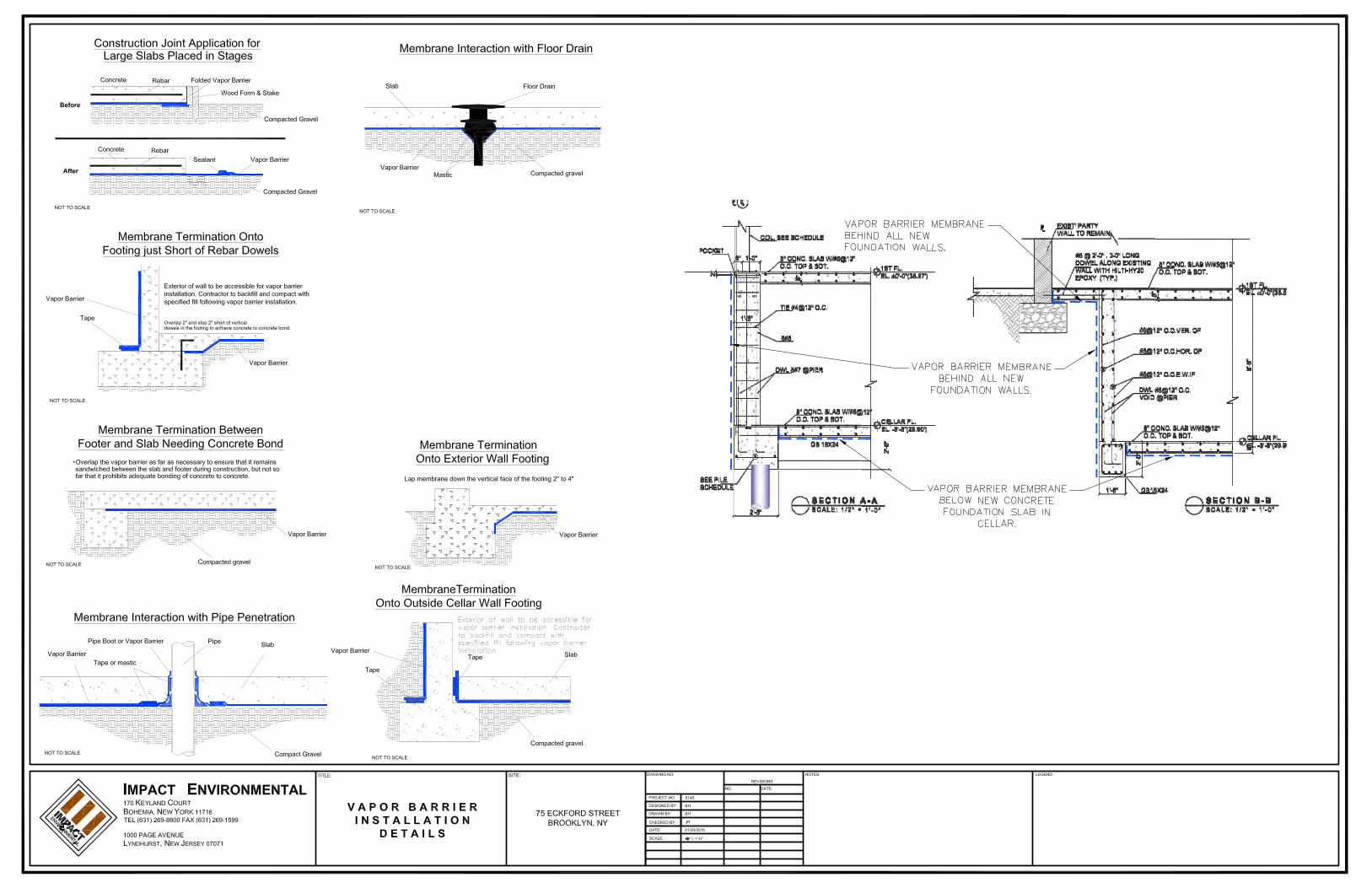
8. Exposure to soil vapor will be mitigated with a combination of building slab and waterproofing /vapor barrier membrane system. The waterproofing /vapor barrier system will consist of “Bituthene 4000”, 60 mils thick, manufactured by W.R. Grace installed behind all two-face foundation walls below grade; “Bituthene Preprufe 160R”, 32 mils thick, manufactured by W.R. Grace installed behind all blind side foundation walls below grade; “Bituthene Preprufe 300R”, 46 mils thick, manufactured by W.R. Grace installed beneath all foundation slabs. Appendix 5 provides manufactures specifications and plans with the extent of the vapor barrier installation with respect to the proposed foundation, footings, etc.
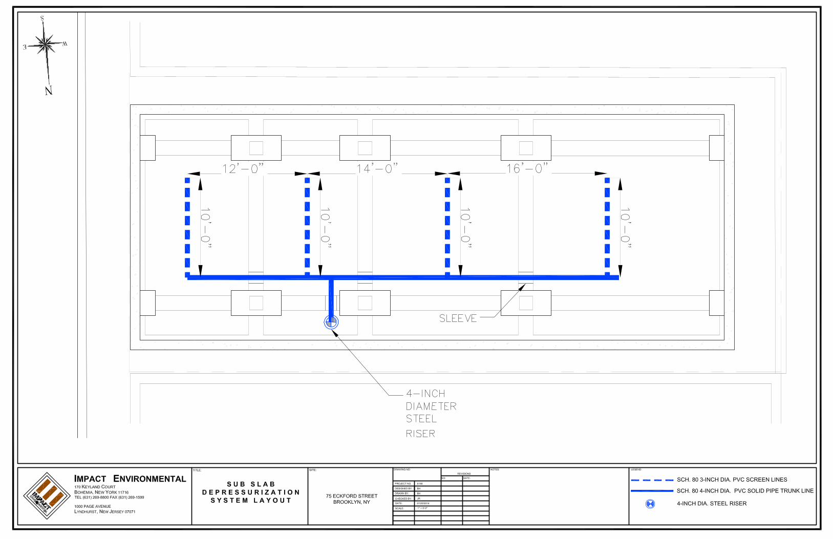
9. An active sub-slab depressurization system (SSDS) will be installed within the building footprint underneath the slab. The SSDS will provide a conduit for potential residual soil gas vapors to vent to the atmosphere. Said SSDS consists of vapor collecting screen/pipes within the building footprint. Schedule 40 slotted PVC screens will be installed within the building footprint underneath the slab-on-grade structure. PVC screens will be installed 1 foot below slab. The screens will be backfilled over and compacted with clean 3/4-inch pea gravel. Total depth of compacted gravel surrounding piping will be a minimum of 10-inches thick. PVC screens are manifolded to 4-inch diameter solid PVC pipes and then to 4-inch diameter steel riser. The riser will raise 3-feet above the roof. A rain cap will be installed at the end of the riser. The SSDS will

3 | P a g e
be operated actively by installation of an inline hard wired electric fan on the riser. Appendix 6 includes the active sub-slab depressurization plan that will be installed beneath the proposed building.
10. Appendix 7 includes the truck route that will be taken by all loaded trucks leaving the Site.
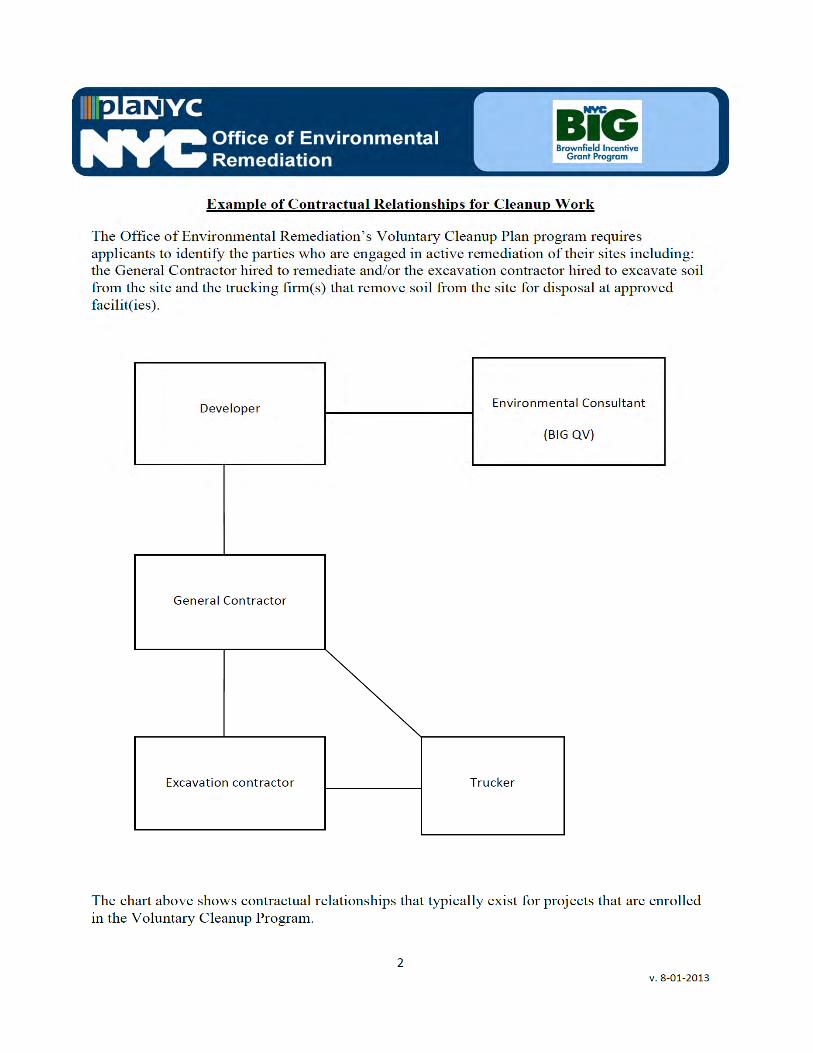
11. OER requires parties seeking City Brownfield Incentive Grants to carry insurance. For a cleanup grant, both the excavator and the trucking firm(s) that handle removal of soil must carry or be covered under a commercial general liability (CGL) policy that provides $1 million per claim in coverage. OER recommends that excavators and truckers also carry contractors pollution liability (CPL) coverage, also providing $1 million per claim in coverage. The CGL policy, and the CPL policy if obtained, must name the City of New York, the NYC Economic Development Corporation, and Brownfield Redevelopment Solutions as additional insured. For an investigation grant, an environmental consultant must be a qualified vendor in the BIG program and carry $1 million of professional liability (PL) coverage. A fact sheet regarding insurance is attached as Appendix 8.
12. Daily report will be provided during active excavation work. If no work is performed for
extended time period, daily report frequency will be reduced to weekly basis. Daily report template is attached in Appendix 9.
13. P.E. signed and stamped RAWP certification page is attached in Appendix 10. Sincerely,
IMPACT ENVIRONMENTAL ENGINEERING PLLC
Joel Rogers, P.E.
Sr. Environmental Engineer
Cc: H. Moore, NYCOER
Appendix 1 Generic Procedures for Management of Underground Storage Tanks
Identified under the NYC VCP
Prior to Tank removal, the following procedures should be followed: Remove all fluid to its lowest draw-off point. Drain and flush piping into the tank. Vacuum out the “tank bottom” consisting of water product and sludge. Dig down to the top of the tank and expose the upper half. Remove the fill tube and disconnect the fill, gauge, product, vent lines and pumps. Cap
and plug open ends of lines. Temporarily plug all tank openings, complete the excavation, remove the tank and place
it in a secure location. Render the tank safe and check the tank atmosphere to ensure that petroleum vapors have
been satisfactorily purged from the tank. Clean tank or remove to storage yard for cleaning. If the tank is to be moved, it must be transported by licensed waste transporter. Plug and
cap all holes prior to transport leaving a 1/8 inch vent hole located at the top of the tank during transport.
After cleaning, the tank must be made acceptable for disposal at a scrap yard, cleaning the tanks interior with a high pressure rinse and cutting the tank in several pieces.
During the tank and pipe line removal, the following field observations should be made and recorded:
A description and photographic documentation of the tank and pipe line condition (pitting, holes, staining, leak points, evidence of repairs, etc.).
Examination of the excavation floor and sidewalls for physical evidence of contamination (odor, staining, sheen, etc.).
Periodic field screening (through bucket return) of the floor and sidewalls of the excavation, with a calibrated photoionization detector (PID).
Impacted Soil Excavation Methods The excavation of the impacted soil will be performed following the removal of the existing tanks. Soil excavation will be performed in accordance with the procedures described under Section 5.5 of Draft DER-10 as follows:
A description and photographic documentation of the excavation. Examination of the excavation floor and sidewalls for physical evidence of contamination
(odor, staining, sheen, etc.). Periodic field screening (through bucket return) of the floor and sidewalls of the
excavation, with calibrated photoionization detector (PID).
Final excavation depth, length, and width will be determined in the field, and will depend on the horizontal and vertical extent of contaminated soils as indentified through physical examination (PID response, odor, staining, etc.). Collection of verification samples will be performed to evaluate the success of the removal action as specified in this document.
The following procedure will be used for the excavation of impacted soil (as necessary and appropriate):
Wear appropriate health and safety equipment as outlined in the Health and Safety Plan. Prior to excavation, ensure that the area is clear of utility lines or other obstructions. Lay
plastic sheeting on the ground next to the area to be excavated. Using a rubber-tired backhoe or track mounted excavator, remove overburden soils and
stockpile, or dispose of, separate from the impacted soil. If additional UST’s are discovered, the NYSDEC will be notified and the best course of
action to remove the structure should be determined in the field. This may involve the continued trenching around the perimeter to minimize its disturbance.
If physically contaminated soil is present (e.g., staining, odors, sheen, PID response, etc.) an attempt will be made to remove it, to the extent not limited by the site boundaries or the bedrock surface. If possible, physically impacted soil will be removed using the backhoe or excavator, segregated from clean soils and overburden, and staged on separated dedicated plastic sheeting or live loaded into trucks from the disposal facility. Removal of the impacted soils will continue until visibly clean material is encountered and monitoring instruments indicate that no contaminants are present.
Excavated soils which are temporarily stockpiled on-site will be covered with tarp material while disposal options are determined. Tarp will be checked on a daily basis and replaced, repaired or adjusted as needed to provide full coverage. The sheeting will be shaped and secured in such a manner as to drain runoff and direct it toward the interior of the property.
Once the site representative and regulatory personnel are satisfied with the removal effort, verification of confirmatory samples will be collected from the excavation in accordance with DER-10.

Appendix 2 NYC VCP Signage

NYC Voluntary Cleanup ProgramThis property is enrolled in the New York City Voluntary
Cleanup Program for environmental remediation. This is avoluntary program administered by the NYC Office of
Environmental Remediation.
For more information, log on to:
www.nyc.gov/oer
If you have questions or would like more information, please contact:
Shaminder Chawla at (212) 788-8841
or email us at [email protected]
75 Eckford Street
Site #: 15CVCP034K

Appendix 3 Proposed Development Plans

CELLAR PLAN
OPEN CELLAR STORAGE
GAS METER ROOM /
SPRINKLER ROOM
ELEC.
METER
BANK
POWDER ROOM
LAUNDRY
CLOSET
UNEXCAVATED AREA
UNEXCAVATED AREA
UNEXCAVATED
AREA
EC
KF
OR
D S
TR
EE
T
A-100.00
CELLAR PLAN
Brooklyn, NY 11214
Tel no. 917-832-0824
161 Bay 46th Street
Tel no. 718-439-8588
4916 3rd Avenue, Brooklyn NY11220
BROOKLYN, NY 11222
DOB #
LOT: 25BLOCK: 2698
BROOKLYN, NY 11222
Tel no. 646-247-0900
75 ECKFORD STREET

REAR YARD
APPENDIX P
BATHROOM
1ST FLOOR PLAN
EC
KF
OR
D S
TR
EE
T
MECH. RM.
KITCHENETTE
LIVING ROOM
A-101.00
1ST FLOOR PLAN
Brooklyn, NY 11214
Tel no. 917-832-0824
161 Bay 46th Street
Tel no. 718-439-8588
4916 3rd Avenue, Brooklyn NY11220
BROOKLYN, NY 11222
DOB #
LOT: 25BLOCK: 2698
BROOKLYN, NY 11222
Tel no. 646-247-0900
75 ECKFORD STREET

CORRIDOR
LIVING ROOM
ROOF
TERRACE
2ND FLOOR PLAN
BATHROOM
EC
KF
OR
D S
TR
EE
T
MECH. RM.
BEDROOM
A-102.00
2ND FLOOR PLAN
Brooklyn, NY 11214
Tel no. 917-832-0824
161 Bay 46th Street
Tel no. 718-439-8588
4916 3rd Avenue, Brooklyn NY11220
BROOKLYN, NY 11222
DOB #
LOT: 25BLOCK: 2698
BROOKLYN, NY 11222
Tel no. 646-247-0900
75 ECKFORD STREET

BEDROOM
MASTER BEDROOM
CORRIDOR
BALCONY
3RD FLOOR PLAN
LIVING ROOM
DINING AREA
KITCHENETTE
BATHROOM
BATHROOM
MECH. RM.
W.I.C.
EC
KF
OR
D S
TR
EE
T
A-103.00
3RD FLOOR PLAN
Brooklyn, NY 11214
Tel no. 917-832-0824
161 Bay 46th Street
Tel no. 718-439-8588
4916 3rd Avenue, Brooklyn NY11220
BROOKLYN, NY 11222
DOB #
LOT: 25BLOCK: 2698
BROOKLYN, NY 11222
Tel no. 646-247-0900
75 ECKFORD STREET

CORRIDOR
BALCONY
4TH FLOOR PLAN
LIVING ROOM
DINING AREA
KITCHENETTE
LIVING ROOM
DINING AREA
KITCHENETTE
BATHROOM
POWDER
ROOM
MECH. RM.
MECH. RM.
EC
KF
OR
D S
TR
EE
T
A-104.00
4TH FLOOR PLAN
Brooklyn, NY 11214
Tel no. 917-832-0824
161 Bay 46th Street
Tel no. 718-439-8588
4916 3rd Avenue, Brooklyn NY11220
BROOKLYN, NY 11222
DOB #
LOT: 25BLOCK: 2698
BROOKLYN, NY 11222
Tel no. 646-247-0900
75 ECKFORD STREET

CORRIDOR
ROOF ROOF
ROOF PLAN / PENTHOUSE
MASTER BEDROOM
BATHROOM
EC
KF
OR
D S
TR
EE
T
EC
KF
OR
D S
TR
EE
T
PENTHOUSE ROOF
PENTHOUSE ROOF PLAN
ROOF STRUCTURES AREA CALCULATION
1968 BC 27-306 COMPLIANCE
A-105.00
ROOF PLAN / PENTHOUSE,
PENTHOUSE ROOF PLAN
Brooklyn, NY 11214
Tel no. 917-832-0824
161 Bay 46th Street
Tel no. 718-439-8588
4916 3rd Avenue, Brooklyn NY11220
BROOKLYN, NY 11222
DOB #
LOT: 25BLOCK: 2698
BROOKLYN, NY 11222
Tel no. 646-247-0900
75 ECKFORD STREET

FRONT ELEVATION
1
REAR ELEVATION
2
A-201.00
FRONT ELEVATION & REAR ELEVATION
Brooklyn, NY 11214
Tel no. 917-832-0824
161 Bay 46th Street
Tel no. 718-439-8588
4916 3rd Avenue, Brooklyn NY11220
BROOKLYN, NY 11222
DOB #
LOT: 25BLOCK: 2698
BROOKLYN, NY 11222
Tel no. 646-247-0900
75 ECKFORD STREET

LONGITUDINAL SECTION
1
OPEN CELLAR STORAGE
DWELLING UNIT#1
( ADA UNITS )
REAR YARD
DINING AREALIVING ROOM ROOF
TERRACE
BATHROOMLIVING ROOM MASTER BEDROOM BALCONY
BALCONY
MASTER BEDROOMROOF TERRACE ROOF TERRACE
ACCESSORY OPEN CELLAR
DWELLING UNIT#2
DWELLING UNIT#3
MECHANICAL
ROOM
BATHROOMLIVING ROOM
DWELLING UNIT#4
MECHANICAL
ROOM
LIVING ROOM
DWELLING UNIT#5
A-301.00
LONGITUDINAL SECTION
Brooklyn, NY 11214
Tel no. 917-832-0824
161 Bay 46th Street
Tel no. 718-439-8588
4916 3rd Avenue, Brooklyn NY11220
BROOKLYN, NY 11222
DOB #
LOT: 25BLOCK: 2698
BROOKLYN, NY 11222
Tel no. 646-247-0900
75 ECKFORD STREET

Appendix 4 Composite Cover Plans

1 2 3 4
A
B
5
15'-5
"7'
-0"
7'-6
"6" 12'-0" 10'-10" 4'-0" 12'-0" 25'-5"
29'-1
1"64'-9"
1 2 1 2 1 2
1 2 1 2 1 21
1
1
1
8" THK. TWO WAY CONC. SLABW/ #5 @12" O.C. TOP & BOT.
P2 60TON
P2 60TON
P1 30TON
P1 30TON
GB 18X24
GB 18X24
GB 18X24
GB 18X24
GB 18X24
GB 18X24
GB 18X24
GB 18X24
GB 18X24 GB 18X24 GB 18X24 GB 18X24
GB 18X24 GB 18X24 GB 18X24 GB 18X24
GB
18X
24
GB
18X
24
GB
18X
24
GB
18X
24
GB
18X
24
CELLAR FLOOR PLANSCALE: 1/4" = 1'-0" T.O.SLAB EL.= -8'-8"
AS109
BS109
EC
KF
OR
D S
T
CS109
P2 60TON
P2 60TON
P2 60TON
P2 60TON
DS109
FOUNDATION AND CELLARFLOOR FRAMING PLAN
2
S-101.00
REV. NO.
NO. 1
ISSUE NO.
DATE DESCRIPTION
DATE ISSUED TO
NO. 1
NO. 2
4916 3rd Avenue, Brooklyn NY 11220Tel. (718) 439 - 8588 | Fax. (347) 799 -1668
[email protected] | www.bcepllc.com
the reproduction of this drawing or the use of ideas andarrangements indicated on this drawing without the writtenapproval of this office is prohibited. written dimensionstake precedence over scaled dimensions. the contractorshall verify dimensions and conditions at the job and reportdiscrepancies to the architect/ engineer prior to the startof the work.
NO. 3
NO. 2
NO. 3
75 ECKFORD ST.BROOKLYN, NEW YORK
02.25.14
75 ECKFORD ST OF 11
14-0107
08-17-2013 GENERAL REVIEW

1 2 3 4
A
B
515
'-5"
7'-0
"7'
-6"
6" 12'-0" 10'-10" 4'-0" 12'-0" 25'-5"
29'-1
1"
64'-9"
1.1
CO
NC
12X
18
8" THK. TWO WAY CONC. SLABW/ #5 @12" O.C. TOP & BOT.
1ST FLOOR PLANSCALE: 1/4" = 1'-0" T.O.SLAB EL. = ±0'-0"
#6 @ 2'-0" , 3-0" LONGDOWEL ALONG EXISTINGWALL WITH HILTI-HY20EPOXY (TYP.)
#6 @ 2'-0" , 3-0" LONGDOWEL ALONG EXISTINGWALL WITH HILTI-HY20EPOXY (TYP.)
ES109
NOTES:1. 8" FLAT SLAB W/#5@12"O.C. TOP & BOTTOM /EA.WAY - MAT REINFORCEMENT.2. ALL REBARS SHOWN ON PLAN ARE ADD'L TO MAT REINFORCEMENT WITH @12" O.C. (TYP.) AND CENTERED ON COLUMN OR START AT EDGE OF SLAB. (U.O.N.).3. ALL REBAR EXPOSED TO WEATHER SHALL BE EPOXY COATED.4. CONCRETE COMPRESSIVE STRENGTH FOR BEAMS, SLABS AND COLUMNS, f'c=4000 PSI.
1ST FLOOR FRAMING PLAN
3
S-102.00
REV. NO.
NO. 1
ISSUE NO.
DATE DESCRIPTION
DATE ISSUED TO
NO. 1
NO. 2
4916 3rd Avenue, Brooklyn NY 11220Tel. (718) 439 - 8588 | Fax. (347) 799 -1668
[email protected] | www.bcepllc.com
the reproduction of this drawing or the use of ideas andarrangements indicated on this drawing without the writtenapproval of this office is prohibited. written dimensionstake precedence over scaled dimensions. the contractorshall verify dimensions and conditions at the job and reportdiscrepancies to the architect/ engineer prior to the startof the work.
NO. 3
NO. 2
NO. 3
75 ECKFORD ST.BROOKLYN, NEW YORK
02.25.14
75 ECKFORD ST OF 11
14-0107
08-17-2013 GENERAL REVIEW

8#8
DWL 8#7 @PIER
2'-6
"
6" 1'-0"
2"
TIE #4@12" O.C.
SEE PILESCHEDULE
2'-6"
GB 18X24
COL. SEE SCHEDULE
8" CONC. SLAB W/#5@12"O.C. TOP & BOT.
8"
8" CONC. SLAB W/#5@12"O.C. TOP & BOT.
1'-6"
CELLAR FL.EL. -8'-8"(29.90')
1ST FL.EL. ±0'-0"(38.57')
GB18X24
8'-8
"
2'-0
"
8"
#5@12" O.C.HOR. OF
1'-6"
#5@12" O.C.E.W.IF
DWL #6@12" O.C.VOID @PIER
#6@12" O.C.VER. OF
8" CONC. SLAB W/#5@12"O.C. TOP & BOT.
8"
EXIST' PARTYWALL TO REMAIN
8" CONC. SLAB W/#5@12"O.C. TOP & BOT.
1ST FL.EL. ±0'-0"(38.57')
CELLAR FL.EL. -8'-8"(29.90')
#6 @ 2'-0" , 3-0" LONGDOWEL ALONG EXISTINGWALL WITH HILTI-HY20EPOXY (TYP.)
W10X26
W10X30 W10X15
TYPICAL BALCONY DETAILSCALE: 3/4" = 1'-0"
PL 28X7X1/2"@ TOP & BOT.W/ (3) 3/4" A325SC
W10X26
FULL WELD
1
1'-3
"1'
-3"
1'-3" 1'-3"
1 2
1'-3
"1'
-3"
1'-3" 2'-6" 1'-3"
5'-0"
2'-6
"
2'-6
"
2'-6"
3RD FLOOR
2ND FLOOR
1ST FLOOR
C O L U M N S C H E D U L E
COL. NO.DATUM EL.
COL. NO.DATUM EL.
COL. NO.
1 1/2"
D
B
B x
D x
T
W/ 4
-3/4
"Ø B
OLT
S
16 X
16
X 1
"
BASE PLATESFLOOR
1 2 43
CELLAR FLOOR
A
5
W/ 4
-3/4
"Ø B
OLT
S
16 X
16
X 1
"
W/ 4
-3/4
"Ø B
OLT
S
16 X
16
X 1
"
W/ 4
-3/4
"Ø B
OLT
S
16 X
16
X 1
"
4TH FLOOR
PENTHOUSE FLOOR
ROOF
CO
NC
. CO
L.18
X18
COL. SPLICE4'-0" ABOVEFIN. FLOOR
B
1 2 43 5
W/ 4
-3/4
"Ø B
OLT
S
16 X
16
X 1
"
W/ 4
-3/4
"Ø B
OLT
S
16 X
16
X 1
"
W/ 4
-3/4
"Ø B
OLT
S
16 X
16
X 1
"
W/ 4
-3/4
"Ø B
OLT
S
16 X
16
X 1
"
W/ 4
-3/4
"Ø B
OLT
S
16 X
16
X 1
"
W/ 4
-3/4
"Ø B
OLT
S
16 X
16
X 1
"
CO
NC
. CO
L.18
X18
CO
NC
. CO
L.18
X18
CO
NC
. CO
L.18
X18
CO
NC
. CO
L.18
X18
CO
NC
. CO
L.18
X18
CO
NC
. CO
L.18
X18
CO
NC
. CO
L.18
X18
CO
NC
. CO
L.18
X18
CO
NC
. CO
L.18
X18
W10
X54
W10
X49
W10
X54
W10
X49
W10
X54
W10
X33
W10
X49
W10
X33
W10
X33
W10
X54
W10
X49
W10
X33
W10
X54
W10
X49
W10
X54
W10
X49
1 2 43 5 1 2 43 5
A B
COLUMN SPLICING NOTES:
1. COLUMN SPLICES SHALL BE LOCATED 4'-0" ABOVEFINISH FLOOR (U.O.N.)
2. SEE DETAIL FOR SPLICES.3. COLUMN ORIENTATION (SEE PLAN)4. ALL LOADS SHOWN ARE GRAVITY LOAD IN KIPS5. PROVIDE STANDARD AISC COLUMN SPLICE DETAIL AT
ALL COLUMNS THAT ARE NOT PART OF WIND/SEISMICFRAMES. FOR ALL COLUMNS IN WIND SEISMIC FRAMES,DESIGN SPLICES FOR 30% OF UPPER COLUMN MOMENTCAPACITY
5. 1/3 STRESS INCREASE IS NOT ALLOWED FOR COLUMNSPLICE DESIGN.
6. SEE LAYOUT FOR OTHER PICK UP COLUMNS.
FOR GRAVITY COLUMN
TYPICAL COLUMN BASE DETAIL
LEVELING SHIMPLATES (TYP.)
BOLTHOLES
CONCTOP OF SEE FDN DET'S
1 1/2"NON-SHRINK GROUT
FOR COLUMN SIZE ANDORIENTATION SEE PLANAND COL SCHED
COL BASE PL FOR SIZE SEECOL SCHED
CL COL & BASEPL
1'-0
"
4 ANCHOR BOLTSTHREADED 6" (MIN.) AT ONEEND WITH STD. REG. HEX.
NUTS AND 12" THKOVERSIZED PLATEWASHERS (UON ON COL.SCHEDULE)
112"Ø GROUT
HOLE
4"
WASHER PLATE
LEVELING SHIMPLATES (TYP.)
1 1/
2" M
IN
CL
CO
L &
BA
SE
PL
1 1/2" MIN
8"1'
-4"
1'-6"
TIE #4@12"
4#8 T & B
8" TWO WAY SLABW/#5@ 12" O.C.E.W
CELLAR FL.EL. -8'-8"(29.90')
8"10
"
1'-0"
TIE #4@12"
3#8 T & B
8" TWO WAY SLABW/#5@ 12" O.C.E.W 1ST FL.
1'-6
"
10
S-109.00
08-17-2013 GENERAL REVIEW
REV. NO.
NO. 1
ISSUE NO.
DATE DESCRIPTION
DATE ISSUED TO
NO. 1
NO. 2
4916 3rd Avenue, Brooklyn NY 11220Tel. (718) 439 - 8588 | Fax. (347) 799 -1668
[email protected] | www.bcepllc.com
the reproduction of this drawing or the use of ideas andarrangements indicated on this drawing without the writtenapproval of this office is prohibited. written dimensionstake precedence over scaled dimensions. the contractorshall verify dimensions and conditions at the job and reportdiscrepancies to the architect/ engineer prior to the startof the work.
NO. 3
NO. 2
NO. 3
75 ECKFORD ST.BROOKLYN, NEW YORK
02.25.14
75 ECKFORD ST OF 11
14-0107
SECTION AND DETAIL

SECTION A-ASCALE: 3/8" = 1'-0"
2'-0"
B.O.FOOTINGEL. -10-8"(27.90')
CELLAR FL.EL. -8'-8"(29.90')
1ST FL.EL. ±0'-0"(38.57')
4'-0"
PL
NEW FOUNDATION WALLSEE STRUC. DWG
NEW FOOTINGSEE STRUC. DWG
WALERW8X24 (TYP)
RAKERW8X24 (TYP)
3'-0"
CONCRETE DEAD MAN (TYP.)
7'-8"
4'-0"
EXIST' PARTY WALL
4'-0"
TIMBER LAGGING3"X10" (TYP)
DET1
DET34'-6"
2'-2"
TIMBER LAGGING3"X10" (TYP)
TAPERED STEELSHIMS @2'-0" O.C.
SELF-UNDERPINNING4000PSI CONC.
2'-0"
NEW FOUNDATIONWALL SEE STRUC. DWG
PL
ADJ. 1-STROTYBRICK
EXIST' WALLTO REMAIN
DET1
3'-0"
SECTION B-BSCALE: 3/8" = 1'-0"
B.O.FOOTINGEL. -10-8"(27.90')
CELLAR FL.EL. -8'-8"(29.90')
1ST FL.EL. ±0'-0"(38.57')
TIMBER LAGGING3"X10" (TYP)
TAPERED STEELSHIMS @2'-0" O.C.
SELF-UNDERPINNING4000PSI CONC.
DET3
UNDERPINNING PITELEVATION VIEW (TYP)
B.O. EXISTING FOOTING
B.O. UNDERPIN.
NEW CONCRETEUNDERPINNING WALL4000 PSI.
T.O.EXISTING GRADE
2'-6" MIN
TIMBER LAGGING3"X10" TO REMAIN
4'-0"
LIFT
VAR
IES
EXISTING FOUNDATIONWALL TO REMAIN
UNDERSIDE OF EXIST' FOUNDATIONSTO BE STIFF BRUSHED AND CLEANEDTO REMOVE ALL LOOSE MATERIALPRIOR TO SHIMS AND DRY PACK (2")
TIMBER SHEETINGTO REMAIN
PIT 3'X4'
2' MI
N.
PL
3'-0"
4"X4" TIMBERBRACES
3"X10" LUMBERALL AROUND
EXIST' FOUNDATIONWALL TO REMAIN
4'-0"
UNDERPINNING PITPLAN (TYP)
RAKER
SECTION VIEW
PL 12X12X1/2BASE PLATE
PLAN VIEW
RAKER/KICKER
CONC. FOOTBLOCK
3'-0" MIN.
MODIFY AS REQ'DFOR MULTIPLERAKERS
(4) 3/4" ANCHORBOLTS WITH 6" MIN.EMBEDMENT
CONCRETEFOOTBLOCK
DET'3 CONCRETE FOOT BLOCK DETAILSCALE: 3/4" = 1'-0"
B.O.EXCAVATION
2'-0"
3'-0"
MIN
.
ANCHOR BOLT 3/4" DIAHOLE 1-1/16" DIA2" 9" 2"
2"9"
2"
1'-0"
1'-0"
BASE PLATE DETAIL(BP 12X12X1/2)
STIFFENER T&BPL 7X3-1/2X1/2
RAKER
SOLDIERBEAM
DET1 TYP.RAKER TO WALERCONNECTION
WALER
1/4"
1/4"
HP8X36 WALER
BRACE HP8X36
PL 7X3-1/2X1/2STIFFENERPLATES BOTHSIDES OF WEB
DET2 TYP. CORNER BRACE TO WALERBEAM CONNECTION
A B C D E
UNDERPINNING SEGMENTPLAN VIEW (TYP.)
BOND BREAK /W WATERPROOFING IF REQ'D
UNDERPINNING SEGMENTSEE PLAN
SHEAR KEY BETWEENSEGMENTS
4916 3rd Avenue, Brooklyn NY 11220Tel. (718) 439 - 8588 | Fax. (347) 799 -1668
[email protected] | www.bcepllc.com
the reproduction of this drawing or the use of ideas andarrangements indicated on this drawing without the writtenapproval of this office is prohibited. written dimensionstake precedence over scaled dimensions. the contractorshall verify dimensions and conditions at the job and reportdiscrepancies to the architect/ engineer prior to the startof the work.
BROOKLYN, NEW YORK 11222
SHORING ANDEXCAVATION PLAN

Appendix 5 Vapor Barrier Specifications and Details

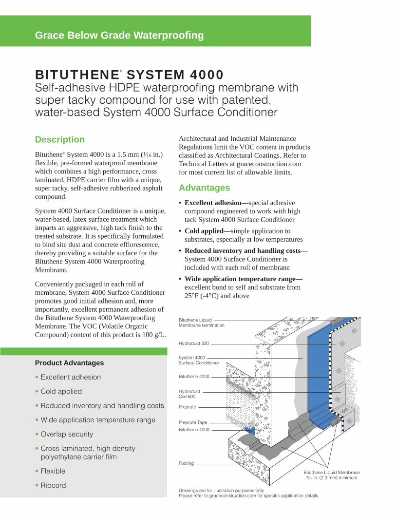
BITUTHENE® SYSTEM 4000Self-adhesive HDPE waterproofing membrane withsuper tacky compound for use with patented, water-based System 4000 Surface Conditioner
Grace Below Grade Waterproofing
Product Advantages
• Excellent adhesion
• Cold applied
• Reduced inventory and handling costs
• Wide application temperature range
• Overlap security
• Cross laminated, high density polyethylene carrier film
• Flexible
• Ripcord
Architectural and Industrial MaintenanceRegulations limit the VOC content in productsclassified as Architectural Coatings. Refer toTechnical Letters at graceconstruction.comfor most current list of allowable limits.
Advantages• Excellent adhesion—special adhesivecompound engineered to work with hightack System 4000 Surface Conditioner
• Cold applied—simple application tosubstrates, especially at low temperatures
• Reduced inventory and handling costs—System 4000 Surface Conditioner isincluded with each roll of membrane
• Wide application temperature range—excellent bond to self and substrate from25°F (-4°C) and above
DescriptionBituthene® System 4000 is a 1.5 mm (1⁄16 in.)flexible, pre-formed waterproof membranewhich combines a high performance, crosslaminated, HDPE carrier film with a unique,super tacky, self-adhesive rubberized asphaltcompound.
System 4000 Surface Conditioner is a unique,water-based, latex surface treatment whichimparts an aggressive, high tack finish to thetreated substrate. It is specifically formulatedto bind site dust and concrete efflorescence,thereby providing a suitable surface for theBituthene System 4000 WaterproofingMembrane.
Conveniently packaged in each roll ofmembrane, System 4000 Surface Conditionerpromotes good initial adhesion and, moreimportantly, excellent permanent adhesion ofthe Bituthene System 4000 WaterproofingMembrane. The VOC (Volatile OrganicCompound) content of this product is 100 g/L.
Drawings are for illustration purposes only. Please refer to graceconstruction.com for specific application details.
Hydroduct 220
Bituthene Liquid Membrane termination
System 4000 Surface Conditioner
Bituthene 4000
Bituthene 4000
Preprufe
Preprufe Tape
Footing
HydroductCoil 600
Bituthene Liquid Membrane3⁄32 in. (2.3 mm) minimum

• Overlap security—minimizes margin forerror under site conditions
• Cross laminated, high density polyethyl-ene carrier film—provides high tearstrength, puncture and impact resistance
• Flexible—accommodates minor structuralmovements and will bridge shrinkagecracks
• Ripcord®—this split release on demandfeature allows the splitting of the releasepaper into two (2) pieces for ease of instal-lation in detailed areas
UseBituthene is ideal for waterproofing concrete,masonry and wood surfaces where in-servicetemperatures will not exceed 135°F (57°C). It can be applied to foundation walls, tunnels,earth sheltered structures and split slabconstruction, both above and below grade.(For above grade applications, see AboveGrade Waterproofing Bituthene System 4000.)
Bituthene is 1⁄16 in. (1.5 mm) thick, 3 ft (0.9 m)wide and 66.7 ft (20 m) long and is suppliedin rolls. It is unrolled sticky side down ontoconcrete slabs or applied onto verticalconcrete faces primed with System 4000Surface Conditioner. Continuity is achievedby overlapping a minimum 2 in. (50 mm) andfirmly rolling the joint.
Bituthene is extremely flexible. It is capableof bridging shrinkage cracks in the concreteand will accommodate minor differentialmovement throughout the service life of thestructure.
Application ProceduresSafety, Storage and Handling InformationBituthene products must be handled properly.Vapors from solvent-based primers andmastic are harmful and flammable. For these products, the best available infor-mation on safe handling, storage, personalprotection, health and environmental consid-erations has been gathered. Material SafetyData Sheets (MSDS) are available at graceconstruction.com and users shouldacquaint themselves with this information.Carefully read detailed precaution statementson product labels and the MSDS before use.
Surface PreparationSurfaces should be structurally sound and freeof voids, spalled areas, loose aggregate andsharp protrusions. Remove contaminants suchas grease, oil and wax from exposed surfaces.Remove dust, dirt, loose stone and debris.Concrete must be properly dried (minimum 7 days for normal structural concrete and 14 days for lightweight structural concrete).
If time is critical, Bituthene Primer B2 orBituthene Primer B2 LVC may be used toallow priming and installation ofmembrane on damp surfaces or greenconcrete. Priming may begin in this case assoon as the concrete will maintain struc-tural integrity. Use form release agentswhich will not transfer to the concrete.Remove forms as soon as possible frombelow horizontal slabs to prevent entrapmentof excess moisture. Excess moisture may leadto blistering of the membrane. Cure concretewith clear, resin-based curing compoundswhich do not contain oil, wax or pigment.Except with Bituthene Primer B2 orBituthene Primer B2 LVC, allow concrete tothoroughly dry following rain. Do not applyany products to frozen concrete.
Repair defects such as spalled or poorlyconsolidated areas. Remove sharp protrusionsand form match lines. On masonry surfaces,apply a parge coat to rough concrete blockand brick walls or trowel cut mortar jointsflush to the face of the concrete blocks.
Temperature• Apply Bituthene System 4000 Membraneand Conditioner only in dry weather andwhen air and surface temperatures are 25°F(-4°C) or above.
• Apply Bituthene Primer B2 or BituthenePrimer B2 LVC in dry weather above 25°F(-4°C). (See separate product informationsheet.)ConditioningBituthene System 4000 Surface Conditioneris ready to use and can be applied by spray orroller. For best results, use a pump-type airsprayer with fan tip nozzle, like the BitutheneSystem 4000 Surface Conditioner Sprayer, toapply the surface conditioner.

Apply Bituthene System 4000 Surface Condi-tioner to clean, dry, frost-free surfaces at acoverage rate of 300 ft2/gal (7.4 m2/L). Cover-age should be uniform. Surface conditionershould not be applied so heavily that itpuddles or runs. Do not apply conditioner toBituthene membrane.
Allow Bituthene System 4000 Surface Condi-tioner to dry one hour or until substratereturns to its original color. At low tempera-tures or in high humidity conditions, dry timemay be longer.
Bituthene System 4000 Surface Conditioneris clear when dry and may be slightly tacky.In general, conditioning should be limited towhat can be covered within 24 hours. In situa-tions where long dry times may prevail,substrates may be conditioned in advance.Substrates should be reconditioned if signifi-cant dirt or dust accumulates.
Before surface conditioner dries, tools shouldbe cleaned with water. After surface condi-tioner dries, tools should be cleaned withmineral spirits. Mineral spirits is acombustible liquid which should be used onlyin accordance with manufacturer’s recom-mendations. Do not use solvents to cleanhands or skin.
Corner DetailsThe treatment of corners varies depending onthe location of the corner. For detailed infor-mation on Bituthene Liquid Membrane, seeseparate product information sheet.
• At wall to footing inside corners—Option 1:Apply membrane to within 1 in.(25 mm) of base of wall. Treat the insidecorner by installing a 3⁄4 in. (20 mm) filletof Bituthene Liquid Membrane. ExtendBituthene Liquid Membrane at least 21⁄2 in.(65 mm) onto footing, and 21⁄2 in. (65 mm)onto wall membrane. Option 2: Treat the inside corner byinstalling a 3⁄4 in. (20 mm) fillet ofBituthene Liquid Membrane. Apply 12 in.(300 mm) wide strip of sheet membranecentered over fillet. Apply wall membraneover inside corner and extend 6 in. (150 mm)onto footing. Apply 1 in. (25 mm) widetroweling of Bituthene Liquid Membraneover all terminations and seams within 12 in. (300 mm) of corner.
• At footings where the elevation of the floorslab is 6 in. (150 mm) or more above thefooting, treat the inside corner either by theabove two methods or terminate themembrane at the base of the wall. Seal thetermination with Bituthene LiquidMembrane.JointsProperly seal all joints with waterstop, jointfiller and sealant as required. Bituthenemembranes are not intended to function as theprimary joint seal. Allow sealants to fullycure. Pre-strip all slab and wall cracks over1⁄16 in. (1.5 mm) wide and all construction andcontrol joints with 9 in. (230 mm) wide sheetmembrane strip.
Application on Horizontal Surfaces(Note: Preprufe® pre-applied membranes arestrongly recommended for below slab or forany application where the membrane isapplied before concreting. See Preprufeproduct information sheets.)
Apply membrane from the low point to thehigh point so that laps shed water. Overlap allseams at least 2 in. (50 mm). Stagger all endlaps. Roll the entire membrane firmly andcompletely as soon as possible. Use alinoleum roller or standard water-filledgarden roller less than 30 in. (760 mm) wide,weighing a minimum of 75 lbs (34 kg) whenfilled. Cover the face of the roller with aresilient material such as a 1⁄2 in. (13 mm)plastic foam or two wraps of indoor-outdoorcarpet to allow the membrane to fully contactthe primed substrate. Seal all T-joints andmembrane terminations with BitutheneLiquid Membrane at the end of the day.
Protrusions and DrainsApply membrane to within 1 in. (25 mm) ofthe base of the protrusion. Apply BitutheneLiquid Membrane 0.1 in. (2.5 mm) thickaround protrusion. Bituthene LiquidMembrane should extend over the membranea minimum of 21⁄2 in. (65 mm) and up thepenetration to just below the finished heightof the wearing course.
Vertical SurfacesApply membrane in lengths up to 8 ft (2.5 m).Overlap all seams at least 2 in. (50 mm). Onhigher walls apply membrane in two or moresections with the upper overlapping the lowerby at least 2 in. (50 mm). Roll all membranewith a hand roller.

Terminate the membrane at grade level. Pressthe membrane firmly to the wall with the buttend of a hardwood tool such as a hammerhandle or secure into a reglet. Failure to useheavy pressure at terminations can result in apoor seal. A termination bar may be used toensure a tight seal. Terminate the membraneat the base of the wall if the bottom of theinterior floor slab is at least 6 in. (150 mm)above the footing. Otherwise, use appropriateinside corner detail where the wall andfooting meet.
Membrane RepairsPatch tears and inadequately lapped seamswith membrane. Clean membrane with adamp cloth and dry. Slit fishmouths and repairwith a patch extending 6 in. (150 mm) in alldirections from the slit and seal edges of thepatch with Bituthene Liquid Membrane.Inspect the membrane thoroughly beforecovering and make any repairs.
DrainageHydroduct® drainage composites are recom-mended for both active drainage andprotection of the membrane. See Hydroductproduct information sheets.
Protection of MembraneProtect Bituthene membranes to avoiddamage from other trades, construction mate-rials or backfill. Place protection immediatelyin temperatures above 77°F (25°C) to avoidpotential for blisters.
• On vertical applications, use Hydroduct 220Drainage Composite. Adhere Hydroduct220 Drainage Composite to membrane withPreprufe Detail Tape. Alternative methodsof protection are to use 1 in. (25 mm)expanded polystyrene or 1⁄4 in. (6 mm)extruded polystyrene that has a minimumcompressive strength of 8 lbs/in.2 (55kN/m2). Such alternatives do not provide
System 4000 Surface Conditioner SprayerThe Bituthene System 4000 SurfaceConditioner Sprayer is a professionalgrade, polyethylene, pump-type,compressed air sprayer with a brass fan tip nozzle. It has a 2 gal (7.6 L) capacity.The nozzle orifice and spray pattern havebeen specifically engineered for theoptimum application of Bituthene System4000 Surface Conditioner.
Hold nozzle 18 in. (450 mm) fromsubstrate and squeeze handle to spray.Spray in a sweeping motion until substrateis uniformly covered.
Sprayer should be repressurized bypumping as needed. For best results,sprayer should be maintained at high pressure during spraying.
To release pressure, invert the sprayer andspray until all compressed air is released.
MaintenanceThe Bituthene System 4000 SurfaceConditioner Sprayer should performwithout trouble for an extended period ifmaintained properly.
Sprayer should not be used to store Bituthene System 4000 Surface Condi-tioner. The sprayer should be flushed withclean water immediately after spraying.For breaks in the spray operation of onehour or less, invert the sprayer and squeezethe spray handle until only air comes fromthe nozzle. This will avoid clogging.
Should the sprayer need repairs or parts,call the maintenance telephone number onthe sprayer tank (800-323-0620).

positive drainage to the system. If 1⁄4 in. (6 mm) extruded polystyrene protectionboard is used, backfill should not containsharp rock or aggregate over 2 in. (50 mm)in diameter. Adhere polystyrene protectionboard with Preprufe Detail Tape.
• In mud slab waterproofing, or other appli-cations where positive drainage is notdesired and where reinforced concrete slabsare placed over the membrane, the use of 1⁄4 in. (6 mm) hardboard or 2 layers of 1⁄8 in.(3 mm) hardboard is recommended.
InsulationAlways apply Bituthene membrane directly toprimed or conditioned structural substrates.Insulation, if used, must be applied over themembrane. Do not apply Bituthene membranesover lightweight insulating concrete.
BackfillPlace backfill as soon as possible. Use careduring backfill operation to avoid damage tothe waterproofing system. Follow generallyaccepted practices for backfilling andcompaction. Backfill should be added andcompacted in 6 in. (150 mm) to 12 in. (300 mm) lifts.
For areas which cannot be fully compacted, atermination bar is recommended across thetop termination of the membrane.
Placing SteelWhen placing steel over properly protectedmembrane, use concrete bar supports (dobies)or chairs with plastic tips or rolled feet toprevent damage from sharp edges. Usespecial care when using wire mesh, especiallyif the mesh is curled.
Approvals• City of Los Angeles Research Report RR 24386
• Miami-Dade County Code Report NOA 04-0114.03
• U.S. Department of Housing and UrbanDevelopment (HUD) HUD MaterialsRelease 628E
• Bituthene 4000 Membranes carry a Under-writers’ Laboratory Class A Fire Rating(Building Materials Directory, File #R7910)when used in either of the followingconstructions:—Limited to noncombustible decks atinclines not exceeding 1⁄4 in. (6 mm) tothe horizontal 1 ft (0.3 m). One layer ofBituthene waterproofing membrane,followed by one layer of 1⁄8 in. (3 mm)protection board, encased in 2 in. (50 mm)minimum concrete monolithic pour.
—Limited to noncombustible decks atinclines not exceeding 1⁄4 in. (6 mm) tothe horizontal 1 ft (0.3 m). One layer ofBituthene waterproofing membrane,followed by one layer of DOW Styro-foam PD Insulation Board [2 in. (50 mm)thick]. This is covered with one layer of2 ft x 2 ft x 2 in. (0.6 m x 0.6 m x 50 mm)of concrete paver topping.
WarrantyFive year material warranties coveringBituthene and Hydroduct products are avail-able upon request. Contact your Grace salesrepresentative for details.
Technical ServicesSupport is provided by full time, technicallytrained Grace representatives and technicalservice personnel, backed by a centralresearch and development staff.

www.graceconstruction.comFor technical assistance call toll free at 866-333-3SBM (3726)
Bituthene, Preprufe, Hydroduct and Ripcord are registered trademarks of W. R. Grace & Co.–Conn.We hope the information here will be helpful. It is based on data and knowledge considered to be true and accurate and is offered for the users’consideration, investigation and verification, but we do not warrant the results to be obtained. Please read all statements, recommendations orsuggestions in conjunction with our conditions of sale, which apply to all goods supplied by us. No statement, recommendation or suggestion isintended for any use which would infringe any patent or copyright. W. R. Grace & Co.–Conn., 62 Whittemore Avenue, Cambridge, MA 02140. In Canada, Grace Canada, Inc., 294 Clements Road, West, Ajax, Ontario, Canada L1S 3C6.This product may be covered by patents or patents pending. Copyright 20013 W. R. Grace & Co.–Conn.BIT-220H Printed in U.S.A. 10/13 FA/PDF
Physical Properties for Bituthene 4000 MembraneProperty Typical Value Test MethodColor Dark gray-blackThickness 1⁄16 in. (1.5 mm) nominal ASTM D3767—method A Flexibility, 180° bend over 1 in. Unaffected ASTM D1970(25 mm) mandrel at -25°F (-32°C)Tensile strength, membrane, die C 325 lbs/in.2 (2240 kPa) minimum ASTM D412 modified1Tensile strength, film 5,000 lbs/in.2 (34.5 MPa) minimum ASTM D882 modified1Elongation, ultimate failure 300% minimum ASTM D412 modified1of rubberized asphaltCrack cycling at -25°F (-32°C), Unaffected ASTM C836100 cyclesLap adhesion at minimum 5 lbs/in. (880 N/m) ASTM D1876 modified2application temperaturePeel strength 9 lbs/in. (1576 N/m) ASTM D903 modified3Puncture resistance, membrane 50 lbs (222 N) minimum ASTM E154Resistance to hydrostatic head 210 ft (70 m) of water ASTM D5385Permeance 0.05 perms (2.9 ng/m2sPa) maximum ASTM E96, section 12—water methodWater absorption 0.1% maximum ASTM D570Footnotes:1. The test is run at a rate of 2 in. (50 mm) per minute.2. The test is conducted 15 minutes after the lap is formed and run at a rate of 2 in. (50 mm) per minute at 40°F (5°C).3. The 180° peel strength is run at a rate of 12 in. (300 mm) per minute.
SupplyBituthene System 4000 3 ft x 66.7 ft roll (200 ft2) [0.9 m x 20 m (18.6 m2)]Roll weight 83 lbs (38 kg) grossPalletization 25 rolls per palletStorage Store upright in dry conditions below 95°F (+35°C).System 4000 Surface Conditioner 1 x 0.625 gal (2.3 L) bottle in each roll of System 4000 MembraneAncillary ProductsSurface Conditioner Sprayer 2 gal (7.6 L) capacity professional grade sprayer with specially engineered nozzleBituthene Liquid Membrane 1.5 gal (5.7 L) pail/125 pails per pallet or 4 gal (15.1 L) pail/48 pails per palletPreprufe Detail Tape 2 in. x 50 ft (50 mm x 15 m) roll/16 rolls per cartonBituthene Mastic Twelve 30 oz (0.9 L) tubes/carton or 5 gal (18.9 L) pail/36 pails per palletComplementary MaterialHydroduct See separate data sheets
Equipment by others: Soft broom, utility knife, brush or roller for priming
Physical Properties for System 4000 Surface ConditionerProperty Typical ValueSolvent type WaterFlash point >140°F (>60°C)VOC* content 91 g/LApplication temperature 25°F (-4°C) and aboveFreeze thaw stability 5 cycles (minimum)Freezing point (as packaged) 14°F (-10°C)Dry time (hours) 1 hour**
* Volatile Organic Compound** Dry time will vary with weather conditions

PREPRUFE® 300R & 160RPre-applied waterproofing membranes that bondintegrally to poured concrete for use below slabs orbehind basement walls on confined sites
Grace Below Grade Waterproofing
Advantages• Forms a unique continuous adhesive bond to
concrete poured against it—prevents water migra-tion and makes it unaffected by ground settlementbeneath slabs
• Fully-adhered watertight laps and detailing• Provides a barrier to water, moisture and gas—physically isolates the structure from the surroundingground
• BBA Certified for basement Grades 2, 3, & 4 to BS 8102:1990
• Zero permeance to moisture• Solar reflective—reduced temperature gain• Simple and quick to install—requiring no primingor fillets
• Can be applied to permanent formwork—allowsmaximum use of confined sites
• Self protecting—can be trafficked immediately afterapplication and ready for immediate placing of rein-forcement
• Unaffected by wet conditions—cannot activateprematurely
• Inherently waterproof, non-reactive system:• not reliant on confining pressures or hydration• unaffected by freeze/thaw, wet/dry cycling
• Chemical resistant—effective in most types of soilsand waters, protects structure from salt or sulphateattack
DescriptionPreprufe® 300R & 160R membranes are unique compos-ite sheets comprising a thick HDPE film, an aggressivepressure sensitive adhesive and a weather resistantprotective coating.Unlike conventional non-adhering membranes, whichare vulnerable to water ingress tracking between theunbonded membrane and structure, the unique Preprufebond to concrete prevents ingress or migration of wateraround the structure.The Preprufe R System includes:• Preprufe 300R—heavy-duty grade for use belowslabs and on rafts (i.e. mud slabs). Designed to acceptthe placing of heavy reinforcement using conven-tional concrete spacers.
• Preprufe 160R—thinner grade for blindside, zeroproperty line applications against soil retentionsystems.
• Preprufe Tape LT—for covering cut edges, rollends, penetrations and detailing (temperaturesbetween 25°F (-4°C) and 86°F (+30°C)).
• Preprufe Tape HC—as above for use in HotClimates (minimum 50°F (10°C)).
• Bituthene® Liquid Membrane—for sealing aroundpenetrations, etc.
• Adcor™ ES—waterstop for joints in concrete wallsand floors
• Preprufe Tieback Covers—preformed cover for soilretention wall tieback heads
• Preprufe Preformed Corners—preformed insideand outside corners
Preprufe 300R & 160R membranes are applied eitherhorizontally to smooth prepared concrete, carton formsor well rolled and compacted earth or crushed stonesubstrate; or vertically to permanent formwork or adjoin-ing structures. Concrete is then cast directly against theadhesive side of the membranes. The specially devel-oped Preprufe adhesive layers work together to form acontinuous and integral seal to the structure. Preprufe can be returned up the inside face of slab form-work but is not recommended for conventionaltwin-sided formwork on walls, etc. Use Bituthene self-adhesive membrane or Procor® fluid applied membraneto walls after removal of formwork for a fully bondedsystem to all structural surfaces.
Drawings are for illustration purposes only. Please refer to graceconstruction.com for specific application details.97/3325
Watertight and grout tight sealed laps
Slab formwork
Selvedge
Selvedge Adhesive surface of Preprufe300R/160R Membrane
Watertight details

InstallationThe most current application instructions, detail drawings and technical letters can be viewed at graceconstruction.com. For other technical informationcontact your local Grace representative.Preprufe 300R & 160R membranes are supplied inrolls 4 ft (1.2 m) wide, with a selvedge on one side toprovide self-adhered laps for continuity between rolls.The rolls of Preprufe Membrane and Preprufe Tape areinterwound with a disposable plastic release linerwhich must be removed before placing reinforcementand concrete.Substrate PreparationAll surfaces—It is essential to create a sound and solidsubstrate to eliminate movement during the concretepour. Substrates must be regular and smooth with nogaps or voids greater than 0.5 in. (12 mm). Groutaround all penetrations such as utility conduits, etc. forstability (see Figure 1).Horizontal—The substrate must be free of looseaggregate and sharp protrusions. Avoid curved orrounded substrates. When installing over earth orcrushed stone, ensure substrate is well compacted toavoid displacement of substrate due to traffic orconcrete pour. The surface does not need to be dry, butstanding water must be removed.Vertical—Use concrete, plywood, insulation or otherapproved facing to sheet piling to provide support tothe membrane. Board systems such as timber laggingmust be close butted to provide support and not morethan 0.5 in. (12 mm) out of alignment.Membrane InstallationPreprufe can be applied at temperatures of 25°F (-4°C)or above. When installing Preprufe in cold or marginalweather conditions 55°F (<13°C) the use of PreprufeTape LT is recommended at all laps and detailing.Preprufe Tape LT should be applied to clean, drysurfaces and the release liner must be removed imme-diately after application. Alternatively, Preprufe LowTemperature (LT) is available for low temperaturecondition applications. Refer to Preprufe LT data sheetfor more information.Horizontal substrates—Place the membrane HDPEfilm side to the substrate with the clear plastic releaseliner facing towards the concrete pour. End laps shouldbe staggered to avoid a build up of layers. Leaveplastic release liner in position until overlap procedureis completed (see Figure 2). Accurately position succeeding sheets to overlap theprevious sheet 3 in. (75 mm) along the markedselvedge. Ensure the underside of the succeeding sheetis clean, dry and free from contamination beforeattempting to overlap. Peel back the plastic release linerfrom between the overlaps as the two layers are bondedtogether. Ensure a continuous bond is achieved withoutcreases and roll firmly with a heavy roller. Completelyremove the plastic liner to expose the protective coating.Any initial tack will quickly disappear.Refer to Grace Tech Letter 15 for information on suitable rebar chairs for Preprufe.Vertical substrates—Mechanically fasten themembrane vertically using fasteners appropriate to thesubstrate with the the clear plastic release liner facingtowards the concrete pour. The membrane may beinstalled in any convenient length. Fastening can bemade through the selvedge using a small and lowprofile head fastener so that the membrane lays flat andallows firmly rolled overlaps. Immediately remove theplastic release liner. Ensure the underside of the succeeding sheet is clean,dry and free from contamination before attempting to
overlap. Roll firmly to ensure a watertight seal. Roll ends and cut edges—Overlap all roll ends and cutedges by a minimum 3 in. (75 mm) and ensure the areais clean and free from contamination, wiping with adamp cloth if necessary. Allow to dry and applyPreprufe Tape LT (or HC in hot climates) centered overthe lap edges and roll firmly (see Figure 3). Immediatelyremove printed plastic release liner from the tape.DetailsRefer to Preprufe Field Application Manual, Section VApplication Instructions or visit graceconstruction.com.This manual gives comprehensive guidance and standard details.Membrane RepairInspect the membrane before installation of reinforce-ment steel, formwork and final placement of concrete.The membrane can be easily cleaned by power washingif required. Repair damage by wiping the area with adamp cloth to ensure the area is clean and free fromdust, and allow to dry. Repair small punctures (0.5 in.(12 mm) or less) and slices by applying Preprufe Tapecentered over the damaged area and roll firmly. Removethe release liner from the tape. Repair holes and largepunctures by applying a patch of Preprufe membrane,which extends 6 in. (150 mm) beyond the damagedarea. Seal all edges of the patch with Preprufe Tape,remove the release liner from the tape and roll firmly.Any areas of damaged adhesive should be covered withPreprufe Tape. Remove printed plastic release linerfrom tape. Where exposed selvedge has lost adhesion orlaps have not been sealed, ensure the area is clean anddry and cover with fresh Preprufe Tape, rolling firmly.Alternatively, use a hot air gun or similar to activateadhesive and firmly roll lap to achieve continuity.Pouring of ConcreteEnsure the plastic release liner is removed from all areas of Preprufe membrane and tape.It is recommended that concrete be poured within 56 days (42 days in hot climates) of application of themembrane. Following proper ACI guidelines, concretemust be placed carefully and consolidated properly toavoid damage to the membrane. Never use a sharpobject to consolidate the concrete.Removal of FormworkPreprufe membranes can be applied to removable form-work, such as slab perimeters, elevator and lift pits, etc.Once the concrete is poured the formwork must remainin place until the concrete has gained sufficientcompressive strength to develop the surface bond.Preprufe membranes are not recommended for conven-tional twin-sided wall forming systems.A minimum concrete compressive strength of 1500 psi(10 N/mm2) is recommended prior to stripping form-work supporting Preprufe membranes. Prematurestripping may result in displacement of the membraneand/or spalling of the concrete. Refer to Grace Tech Letter 17 for information onremoval of formwork for Preprufe.
Figure 1
Figure 2
Figure 3

1 Preprufe 300R 5 Procor 8 Hydroduct®2 Preprufe 160R 6 Bituthene Liquid Membrane 9 Adcor ES3 Preprufe Tape 7 Protection 10 Preprufe CJ Tape4 Bituthene
1
1
3 4
13
4
Wall base detail against permanent shutter
Bituthene wall base detail (Option 1) Procor wall base detail (Option 1)
Bituthene wall base detail (Option 2) Procor wall base detail (Option 2)
line ofpermanentformwork
4 in. (100 mm)minimum
6 in. (150 mm) 6 in. (150 mm)
3 in. (75 mm)
8
8
6
4
8
8
5
8or7
6
4
1
3
2
1
Detail DrawingsDetails shown are typical illustrations and notworking details. For a list of the most currentdetails, visit us at graceconstruction.com. For technical assistance with detailing andproblem solving please call toll free at 866-333-3SBM (3726).
3
13
1
8or7
5
5
1
3
3
4 in. (100 mm)minimum 4 in. (100 mm)
minimum
9
10
9
5
9
6
9
6
9

www.graceconstruction.comFor technical assistance call toll free at 866-333-3SBM (3726)
Adcor is a trademark and Preprufe, Bituthene and Hydroduct are registered trademarks of W. R. Grace & Co.–Conn.Procor is a U.S. registered trademark of W. R. Grace & Co.–Conn., and is used in Canada under license from PROCOR LIMITED.We hope the information here will be helpful. It is based on data and knowledge considered to be true and accurate and is offered for the users’consideration, investigation and verification, but we do not warrant the results to be obtained. Please read all statements, recommendations orsuggestions in conjunction with our conditions of sale, which apply to all goods supplied by us. No statement, recommendation or suggestion isintended for any use which would infringe any patent or copyright. W. R. Grace & Co.–Conn., 62 Whittemore Avenue, Cambridge, MA 02140. In Canada, Grace Canada, Inc., 294 Clements Road, West, Ajax, Ontario, Canada L1S 3C6.This product may be covered by patents or patents pending. Copyright 2012. W. R. Grace & Co.–Conn.PF-111H Printed in U.S.A. 07/12 FA/PDF
Physical PropertiesProperty Typical Value 300R Typical Value 160R Test MethodColor white whiteThickness 0.046 in. (1.2 mm) 0.032 in. (0.8 mm) ASTM D3767Lateral Water Migration Pass at 231 ft (71 m) of Pass at 231 ft (71 m) of ASTM D5385, modified1
Resistance hydrostatic head pressure hydrostatic head pressureLow temperature flexibility Unaffected at -20°F (-29°C) Unaffected at -20°F (-29°C) ASTM D1970Resistance to hydrostatic 231 ft (71 m) 231 ft (71 m) ASTM D5385, head modified2
Elongation 500% 500% ASTM D412, modified3
Tensile strength, film 4000 psi (27.6 MPa) 4000 psi (27.6 MPa) ASTM D412Crack cycling at -9.4°F Unaffected, Pass Unaffected, Pass ASTM C836(-23°C), 100 cyclesPuncture resistance 221 lbs (990 N) 100 lbs (445 N) ASTM E154Peel adhesion to concrete 5 lbs/in. (880 N/m) 5 lbs/in. (880 N/m) ASTM D903, modified4
Lap peel adhesion 5 lbs/in. (880 N/m) 5 lbs/in. (880 N/m) ASTM D1876, modified5
Permeance to water 0.01 perms 0.01 perms ASTM E96, method Bvapor transmission (0.6 ng/(Pa x s x m2)) (0.6 ng/(Pa x s x m2))Water absorption 0.5% 0.5% ASTM D570
Footnotes:1. Lateral water migration resistance is tested by casting concrete against membrane with a hole and subjecting the membrane to hydrostatic head pressure withwater. The test measures the resistance of lateral water migration between the concrete and the membrane.
2. Hydrostatic head tests of Preprufe Membranes are performed by casting concrete against the membrane with a lap. Before the concrete cures, a 0.125 in. (3 mm) spacer is inserted perpendicular to the membrane to create a gap. The cured block is placed in a chamber where water is introduced to themembrane surface up to the head indicated.
3. Elongation of membrane is run at a rate of 2 in. (50 mm) per minute.4. Concrete is cast against the protective coating surface of the membrane and allowed to properly dry (7 days minimum). Peel adhesion of membrane toconcrete is measured at a rate of 2 in. (50 mm) per minute at room temperature.
5. The test is conducted 15 minutes after the lap is formed (per Grace published recommendations) and run at a rate of 2 in. (50 mm) per minute.
SupplyDimensions (Nominal) Preprufe 300R Membrane Preprufe 160R Membrane Preprufe Tape (LT or HC*)Thickness 0.046 in. (1.2 mm) 0.032 in. (0.8 mm)Roll size 4 ft x 98 ft (1.2 m x 30 m) 4 ft x 115 ft (1.2 m x 35 m) 4 in. x 49 ft (100 mm x 15 m)Roll area 392 ft2 (36 m2) 460 ft2 (42 m2)Roll weight 108 lbs (50 kg) 92 lbs (42 kg) 4.3 lbs (2 kg)Minimum side/end laps 3 in. (75 mm) 3 in. (75 mm) 3 in. (75 mm)* LT denotes Low Temperature (between 25°F (-4°C) and 86°F (+30°C))HC denotes Hot Climate (50°F (>+10°C))Ancillary Products
Bituthene Liquid Membrane—1.5 US gal (5.7 liter) or 4 US gal (15.1 liter)
Specification ClausesPreprufe 300R or 160R shall be applied with its adhe-sive face presented to receive fresh concrete to which itwill integrally bond. Only Grace Construction Productsapproved membranes shall be bonded to Preprufe300R/160R. All Preprufe 300R/160R system materialsshall be supplied by Grace Construction Products, andapplied strictly in accordance with their instructions.Specimen performance and formatted clauses are alsoavailable.
NOTE: Use Preprufe Tape to tie-in Procor with Preprufe.Health and SafetyRefer to relevant Material Safety data sheet. Completerolls should be handled by a minimum of two persons.

Appendix 6 Active SSDS Plans


Appendix 7 Truck Route

Appendix 8
BIG Program Insurance Fact Sheet


Appendix 9 Daily Report Template

Generic Template for Daily Status Report
Instructions
The Daily Status Report submitted to OER should adhere to the following conventions:
Remove this cover sheet prior to editing.
Remove all the red text and replace with site‐specific information.
Submit the final version as a Word or PDF file.
Daily Status Reports
Daily status reports providing a general summary of activities for each day of active remedial work will be emailed to the OER Project Manager by the end of the following day. Those reports will include:
Project number and statement of the activities and an update of progress made and locations of work
performed;
Quantities of material imported and exported from the Site;
Status of on‐Site soil/fill stockpiles;
A summary of all citizen complaints, with relevant details (basis of complaint; actions taken; etc.);
A summary of CAMP excursions, if any;
Photograph of notable Site conditions and activities.
The frequency of the reporting period may be revised in consultation with OER project manager based on planned project tasks. Daily email reports are not intended to be the primary mode of communication for notification to OER of emergencies (accidents, spills), requests for changes to the RAWP or other sensitive or time critical information. However, such information will be included in the daily reports. Emergency conditions and changes to the RAWP will be communicated directly to the OER project manager by personal communication. Daily reports will be included as an Appendix in the Remedial Action Report.
Daily Status Report Template
Version 1.3
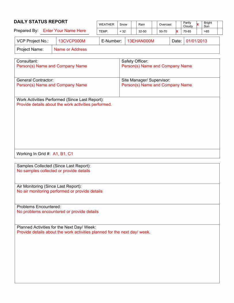
DAILY STATUS REPORT
Prepared By: Enter Your Name Here
VCP Project No.: 13CVCP000M E-Number: 13EHAN000M Date: 01/01/2013
Project Name: Name or Address
Consultant: Person(s) Name and Company Name
Safety Officer:Person(s) Name and Company Name
General Contractor: Person(s) Name and Company Name
Site Manager/ Supervisor: Person(s) Name and Company Name
Work Activities Performed (Since Last Report):Provide details about the work activities performed.
Working In Grid #: A1, B1, C1
Samples Collected (Since Last Report): No samples collected or provide details Air Monitoring (Since Last Report): No air monitoring performed or provide details Problems Encountered: No problems encountered or provide details Planned Activities for the Next Day/ Week:Provide details about the work activities planned for the next day/ week.
WEATHER Snow Rain Overcast Partly Cloudy
X Bright Sun
TEMP. < 32 32-50 50-70 X 70-85 >85

Facility # Name/ Location Type of Waste Solid Or Liquid
Facility # Name Location Type of Waste Solid Or Liquid
Facility # Name Location Type of Waste Solid Or Liquid
Facility # Name Location Type of Waste Solid Or Liquid
Facility # Name Location Type of Waste Solid Or Liquid
# # # # # # # Clean Earth Carteret, NJ petroleum soils Solid
(Trucks, Cu.Yds. Or Gallons)
Trucks Cu. Yds. Or Gallons
Trucks Cu. Yds. Or Gallons
Trucks Cu. Yds. Or Gallons
Trucks Cu. Yds. Or Gallons
Trucks Cu. Yds.
Today 5 120
Total 25 600
NYC Clean Soil Bank Receiving Facility:Name/ Address (Approved by OER)
Tracking No.: 13CCSB000
Today Trucks 5
Cu. Yds. 25 Total Trucks
120 Cu. Yds. 600
Site Grid Map Insert the site grid map here
Example:

Photo Log
Photo 1 – provide a caption Insert Photo Here – Photo of the entire site
Photo 2 – provide a caption Insert Photo Here – Photo of the work activities performed
Photo 3 – provide a caption Insert Photo Here – Photo of the work activities performed

Appendix 10 RAWP Certification Page

CERTIFICATION
I, Joel Rogers, am a Professional Engineer licensed in the State of New York. I have primary direct responsibility
for implementation of the remedial action for the redevelopment project located at 75 Eckford Street in Brooklyn,
NY. OER project number 14EHAZ403K and Voluntary Cleanup Program Site Number 15CVCP034K.
I certify that this Remedial Action Work Plan (RAWP) has a plan for handling, transport and disposal of soil, fill,
fluids and other materials removed from the property in accordance with applicable City, State and Federal laws and
regulations. Importation of all soil, fill and other material from off-Site will be in accordance with all applicable
City, State and Federal laws and requirements. This RAWP has provisions to control nuisances during the
remediation and all invasive work, including dust and odor suppression.
Joel M. Rogers Name 083034 NYS PE License Number
Signature
1/27/15 Date