epl606 · 2014-09-22 · ip internet • concatenation of networks • protocol stack 2 r2 r1 h4 h5...
TRANSCRIPT

EPL606Internetworking
Part 2c
1

IP Internet • Concatenation of Networks
• Protocol Stack
2
R2
R1
H4
H5
H3H2H1
Network 2 (Ethernet)
Network 1 (Ethernet)
H6
Network 4(point-to-point)
H7 R3 H8
Network 3 (FDDI)
R1 R2 R3
H1 H8
ETH FDDI
IP
ETH
TCP
FDDI PPP PPP ETH
IP
ETH
TCP
IP IP IP

Datagram Forwarding • Strategy every datagram contains destination’s address if connected to destination network, then forward to host if not directly connected, then forward to some router forwarding table maps network number into next hop each host has a default router each router maintains a forwarding table
• Example (R2) Network Number Next Hop
1 R32 R13 interface 14 interface 0
3

Address Translation • Map IP addresses into physical addresses destination host next hop router
• Techniques encode physical address in host part of IP address table-based
• ARP table of IP to physical address bindings broadcast request if IP address not in table target machine responds with its physical address table entries are discarded if not refreshed
4

ARP– The Address Resolution Protocol
Three interconnected /24 networks: two Ethernets and an FDDI ring.

ARP Details • Request Format HardwareType: type of physical network (e.g., Ethernet) ProtocolType: type of higher layer protocol (e.g., IP) HLEN & PLEN: length of physical and protocol
addresses Operation: request or response Source/Target-Physical/Protocol addresses
• Notes table entries timeout in about 10 minutes update table with source when you are the target update table if already have an entry do not refresh table entries upon reference
6

ARP Packet Format
7
TargetHardwareAddr (bytes 2 5)
TargetProtocolAddr (bytes 0 3)
SourceProtocolAddr (bytes 2 3)
Hardware type = 1 ProtocolType = 0x0800
SourceHardwareAddr (bytes 4 5)
TargetHardwareAddr (bytes 0 1)
SourceProtocolAddr (bytes 0 1)
HLen = 48 PLen = 32 Operation
SourceHardwareAddr (bytes 0― 3)
0 8 16 31
―
―
― ―
―
―

Internet Control Message Protocol (ICMP)• Echo (ping)
• Redirect (from router to source host)
• Destination unreachable (protocol, port, or host)
• TTL exceeded (so datagrams don’t cycle forever)
• Checksum failed
• Reassembly failed
• Cannot fragment
8

NAT: network address translation
Net
wor
k La
yer
4-9
10.0.0.1
10.0.0.2
10.0.0.3
10.0.0.4
138.76.29.7
local network(e.g., home network)
10.0.0/24
rest ofInternet
datagrams with source or destination in this networkhave 10.0.0/24 address for source, destination (as usual)
all datagrams leaving localnetwork have same single
source NAT IP address: 138.76.29.7,different source
port numbers

NAT: network address translationmotivation: local network uses just one IP address as far as outside world is concerned:range of addresses not needed from ISP: just one IP address for all devicescan change addresses of devices in local network without notifying outside worldcan change ISP without changing addresses of devices in local networkdevices inside local net not explicitly addressable, visible by outside world (a security plus) N
etw
ork
Laye
r
4-10

NAT: network address translation
implementation: NAT router must: outgoing datagrams: replace (source IP address, port #)
of every outgoing datagram to (NAT IP address, new port #). . . remote clients/servers will respond using (NAT IP
address, new port #) as destination addr
remember (in NAT translation table) every (source IP address, port #) to (NAT IP address, new port #) translation pair
incoming datagrams: replace (NAT IP address, new port #) in dest fields of every incoming datagram with corresponding (source IP address, port #) stored in NAT table
Net
wor
k La
yer
4-11

NAT: network address translation
4-12
10.0.0.1
10.0.0.2
10.0.0.3
S: 10.0.0.1, 3345D: 128.119.40.186, 80
1
10.0.0.4
138.76.29.7
1: host 10.0.0.1 sends datagram to 128.119.40.186, 80
NAT translation tableWAN side addr LAN side addr
138.76.29.7, 5001 10.0.0.1, 3345…… ……
S: 128.119.40.186, 80 D: 10.0.0.1, 3345 4
S: 138.76.29.7, 5001D: 128.119.40.186, 802
2: NAT routerchanges datagramsource addr from10.0.0.1, 3345 to138.76.29.7, 5001,updates table
S: 128.119.40.186, 80 D: 138.76.29.7, 5001 3
3: reply arrivesdest. address:138.76.29.7, 5001
4: NAT routerchanges datagramdest addr from138.76.29.7, 5001 to 10.0.0.1, 3345

NAT: network address translation• 16-bit port-number field: 60,000 simultaneous connections with a single LAN-side
address!
• NAT is controversial: routers should only process up to layer 3 violates end-to-end argument NAT possibility must be taken into account by app
designers, e.g., P2P applications address shortage should instead be solved by IPv6
Net
wor
k La
yer
4-13

NAT traversal problem• client wants to connect
to server with address 10.0.0.1 server address 10.0.0.1
local to LAN (client can’t use it as destination addr)
only one externally visible NATed address: 138.76.29.7
• solution1: statically configure NAT to forward incoming connection requests at given port to server e.g., (123.76.29.7, port
2500) always forwarded to 10.0.0.1 port 25000
Net
wor
k La
yer
4-14
10.0.0.1
10.0.0.4
NAT router
138.76.29.7
client?

NAT traversal problemsolution 2: Universal
Plug and Play (UPnP) Internet Gateway Device (IGD) Protocol. Allows NATed host to: learn public IP address
(138.76.29.7) add/remove port
mappings (with lease times)
i.e., automate static NAT port map configuration N
etw
ork
Laye
r
4-15
10.0.0.1
NAT router
IGD

NAT traversal problemsolution 3: relaying (used in Skype) NATed client establishes connection to relay external client connects to relay relay bridges packets between to connections
Net
wor
k La
yer
4-16
138.76.29.7client
1. connection torelay initiatedby NATed host
2. connection torelay initiatedby client 3. relaying
establishedNAT router
10.0.0.1

ICMP: internet control message protocol• used by hosts & routers to
communicate network-level information error reporting:
unreachable host, network, port, protocol
echo request/reply (used by ping)
• network-layer “above”IP: ICMP msgs carried in IP
datagrams
• ICMP message: type, code plus first 8 bytes of IP datagram causing error
Type Code description0 0 echo reply (ping)3 0 dest. network unreachable3 1 dest host unreachable3 2 dest protocol unreachable3 3 dest port unreachable3 6 dest network unknown3 7 dest host unknown4 0 source quench (congestion
control - not used)8 0 echo request (ping)9 0 route advertisement10 0 router discovery11 0 TTL expired12 0 bad IP header
Net
wor
k La
yer
4-17

Traceroute and ICMP• source sends series of
UDP segments to dest first set has TTL =1 second set has TTL=2, etc. unlikely port number
• when nth set of datagrams arrives to nth router: router discards datagrams and sends source ICMP
messages (type 11, code 0) ICMP messages includes
name of router & IP address
• when ICMP messages arrives, source records RTTs
• stopping criteria: UDP segment eventually
arrives at destination host destination returns ICMP “port unreachable”message (type 3, code 3)
source stops
Net
wor
k La
yer
4-18
3 probes
3 probes
3 probes
Next Generation IP (IPv6)
Net
work
Lay
er
19

Net
wor
k La
yer
20
Size of the Internet
0
1000
2000
3000
4000
5000
6000
1988
1989
1990
1991
1992
1993
1994
1995
1996
1997
1998
1999
2000
2001
2002
2003
2004
2005
2006
2007
Theoretical Usable
IPv4 Doomsday ?
Approx. 27% remain unallocated
Distribution Statement A: Cleared for Public Release; Distribution is unlimited.

Net
wor
k La
yer
21
Internet BGP Routing Table
Exponential Growth
No
Gro
wth
Linear Growth
CIDR deployment
Exp
onen
tialG
row
th-C
IDR
brea
king
dow
n
http://www.telstra.net/ops/bgptable.html
Distribution Statement A: Cleared for Public Release; Distribution is unlimited.

Net
wor
k La
yer
22
What about technologies & efforts to slow the consumption rate?
• Dial-access / PPP / DHCPProvides temporary allocation aligned with actual endpoint use.
• Strict allocation policiesReduced allocation rates by policy of ‘current-need’ vs. previous policy based on ‘projected-maximum-size’.
• CIDRAligns routing table size with needs-based address allocation policy. Additional enforced aggregation actually lowered routing table growth rate to linear for a few years.
• NATHides many nodes behind limited set of public addresses.

Net
wor
k La
yer
23
What did intense conservation efforts of the last 5 years buy us?
• Actual allocation history1981 – IPv4 protocol published1985 ~ 1/16 total space1990 ~ 1/8 total space1995 ~ 1/4 total space2000 ~ 1/2 total space
• The lifetime-extending efforts & technologies delivered the ability to absorb the dramatic growth in consumer demand during the late 90’s.
In short they bought – TIME –

Net
wor
k La
yer
24
Would increased use of NATs be adequate?
NO!
• NAT enforces a ‘client-server’ application model where the server has topological constraints. They won’t work for peer-to-peer or devices that are “called” by others (e.g., IP phones) They inhibit deployment of new applications and services, because all NATs in the path have to be upgraded BEFORE the application can be deployed.
• NAT compromises the performance, robustness, and security of the Internet.
• NAT increases complexity and reduces manageability of the local network.
• Public address consumption is still rising even with current NAT deployments.

Net
wor
k La
yer
25
78 Top Level IPv6 ISPs in 26 Countries
APNIC
ARIN
RIPE
02468
10121416
Japa
nUnit
ed StatesS. K
oreaGerm
any
Sweden UKEurop
eFran
ceRussi
aPola
ndNeth
erlands
FinlandTaiw
anChina &
HK
Canada
Mexico
Austria
Switzerla
ndGree
cePort
ugal
BelgiumIta
lyDen
markNorw
ayAustr
alia
Singapo
re
Distribution Statement A: Cleared for Public Release; Distribution is unlimited.

Net
wor
k La
yer
26
78 Top Level IPv6 ISPsin 22 months
RIPE APNICARIN
0102030405060708090
100
Jul-99
Aug-99Sep-99Oct-
99Nov-
99Dec-
99Jan
-00Feb-00Mar-
00Apr-
00May-
00Jun-00Jul-0
0Aug-00Sep-00Oct-
00Nov-
00Dec-
00Jan
-01Feb-01Mar-
01Apr-
01May-
01
Distribution Statement A: Cleared for Public Release; Distribution is unlimited.

Net
wor
k La
yer
27
What Ever Happened to IPv5?
0 IP March 1977 version (deprecated)
1 IP January 1978 version (deprecated)
2 IP February 1978 version A (deprecated)
3 IP February 1978 version B (deprecated)
4 IPv4 September 1981 version (current widespread)
5 ST Stream Transport (not a new IP, little use)
6 IPv6 December 1998 version (formerly SIP, SIPP)
7 CATNIP IPng evaluation (formerly TP/IX; deprecated)
8 Pip IPng evaluation (deprecated)
9 TUBA IPng evaluation (deprecated)
10-15 unassigned

Net
wor
k La
yer
28
Benefits of 128 bit Addresses• Room for many levels of structured hierarchy
and routing aggregation
• Easy address auto-configuration
• Easier address management and delegation than IPv4
• Ability to deploy end-to-end IPsec(NATs removed as unnecessary)

Net
wor
k La
yer
29
Incidental Benefits of New Deployment
• Chance to eliminate some complexity in IP header improve per-hop processing
• Chance to upgrade functionality multicast, QoS, mobility
• Chance to include new features binding updates

Net
wor
k La
yer
30
IPv6 Enhancements (1)• Expanded address space 128 bit
• Improved option mechanism Separate optional headers between IPv6 header and
transport layer header Most are not examined by intermediate routes Improved speed and simplified router processing Easier to extend options
• Address autoconfiguration Dynamic assignment of addresses

Net
wor
k La
yer
31
IPv6 Enhancements (2)• Increased addressing flexibility Anycast - delivered to one of a set of nodes Improved scalability of multicast addresses
• Support for resource allocation Replaces type of service Labeling of packets to particular traffic flow Allows special handling e.g. real time video

Net
wor
k La
yer
32
Summary of Main IPv6 Benefits
• Expanded addressing capabilities
• Structured hierarchy to manage routing table growth
• Serverless autoconfiguration and reconfiguration
• Streamlined header format and flow identification
• Improved support for options / extensions

Net
wor
k La
yer
33
Types of address• Unicast Single interface
• Anycast Set of interfaces (typically different nodes) Delivered to any one interface the “nearest”
• Multicast Set of interfaces Delivered to all interfaces identified

Net
wor
k La
yer
34
IPv6 Addressing
• Classless addressing/routing (similar to CIDR)• Notation: x:x:x:x:x:x:x:x (x = 16-bit hex number) contiguous 0s are compressed: 47CD::A456:0124 IPv6 compatible IPv4 address: ::128.42.1.87
• Address assignment provider-based (can’t change provider easily) geographic
010 Registry ID Provider ID Subscriber ID Subnet ID Interface ID
n bits m bits o bits p bits (125-m-n-o-p) bits

The Main IPv6 Header• The IPv6 fixed header (required).
Net
wor
k La
yer
35

Net
wor
k La
yer
36
IPv6 Header (Cont)Priority: identify priority among datagrams in flowFlow Label: identify datagrams in same “flow.”
(concept of“flow” not well defined).Next header: identify upper layer protocol for data
Checksum: removed entirely to reduce processing time at each hopOptions: allowed, but outside of header, indicated by “Next Header” fieldICMPv6: new version of ICMP
additional message types, e.g. “Packet Too Big”multicast group management functions
Changes from IPv4
Net
wor
k La
yer
37
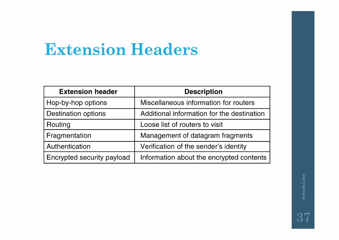
Extension Headers
IPv6 extension headers.5-69

Transition from IPv4 to IPv6• not all routers can be upgraded simultaneously no “flag days” how will network operate with mixed IPv4 and IPv6
routers?
• tunneling: IPv6 datagram carried as payload in IPv4 datagram among IPv4 routers
Net
wor
k La
yer
4-38
IPv4 source, dest addr IPv4 header fields
IPv4 datagramIPv6 datagram
IPv4 payload
UDP/TCP payloadIPv6 source dest addr
IPv6 header fields