caponordcdnmedia.endeavorsuite.com/.../aprilia_caponord120… · · 2014-03-31control buttons ......
TRANSCRIPT

APRILIA WOULD LIKE TO THANK YOU
for choosing one of its products. We have drawn up this booklet to provide a comprehensive overview of your vehicle's quality features. Please read itcarefully before riding the vehicle for the first time. It contains information, tips and precautions for using your vehicle It also describes features, detailsand devices to assure you that you have made the right choice. We believe that if you follow our suggestions, you will soon get to know your new vehiclewell and will use it for a long time at full satisfaction. This booklet is an integral part of the vehicle, and should the vehicle be sold, it must be transferredto the new owner.
CAPONORD
Ed. 01_03/2014

The instructions given in this manual are intended to provide a clear, simple guide to using your vehicle; it also describes routine maintenance proceduresand regular checks that should be carried out on the vehicle at an Aprilia Dealer or Authorised Workshop. The booklet also contains instructions forsimple repairs. Any operations not specifically described in this booklet require the use of special tools and/or particular technical knowledge: for theseoperations, please take your vehicle to an Aprilia Dealer or Authorised Workshop.
2

Personal safety
Failure to completely observe these instructions will result in serious risk of personalinjury.
Safeguarding the environment
Sections marked with this symbol indicate the correct use of the vehicle to prevent dam-aging the environment.
Vehicle intactness
The incomplete or non-observance of these regulations leads to the risk of seriousdamage to the vehicle and sometimes even the invalidity of the guarantee
The symbols illustrated above are very important. They are used to highlight parts of thebooklet that should be read with particular care. The different symbols are used to makeeach topic in the manual simple and quick to locate. Before starting the engine, read thisbooklet carefully, particularly the "SAFE RIDING" section. Your safety as well as other'sdoes not only depend on the quickness of your reflexes and agility, but also on how wellyou know your vehicle, the state of maintenance of the vehicle itself and your knowledgeof the rules for SAFE RIDING. For your safety, get to know your vehicle well so as tosafely ride and master it given any riding condition. IMPORTANT This booklet is anintegral part of the vehicle, and must be handed to the new owner in the event of sale.
3

4

INDEX
GENERAL RULES....................................................................... 7Foreword............................................................................... 8Motorcycle care..................................................................... 8Carbon monoxide.................................................................. 11Fuel....................................................................................... 12Hot components.................................................................... 12The braking........................................................................... 13Warning lights........................................................................ 13Coolant.................................................................................. 14Used engine oil and gearbox oil............................................ 15Brake and clutch fluid............................................................ 15Battery hydrogen gas and electrolyte.................................... 16Stand..................................................................................... 16Reporting of defects that affect safety................................... 17
VEHICLE...................................................................................... 19Arrangement of the main components...................................... 21Dashboard................................................................................ 26Instrument panel....................................................................... 27Light unit................................................................................... 29Digital lcd display...................................................................... 29
Alarms................................................................................... 38Mapping selection................................................................. 39Control buttons...................................................................... 41Ignition switch........................................................................ 49Locking the steering wheel.................................................... 50
Horn button............................................................................... 50Switch direction indicators........................................................ 51High/low beam selector............................................................. 52Passing button.......................................................................... 52Heated handgrip control............................................................ 53Start-up button.......................................................................... 54Engine stop switch.................................................................... 54Button Cruise Control................................................................ 54
System ABS.............................................................................. 57System ATC (Aprilia Traction Control)...................................... 60ADD system (Aprilia Dynamic Damping).................................. 63
Immobilizer system operation................................................ 65Opening the saddle............................................................... 66Glove/tool kit compartment.................................................... 67USB Port............................................................................... 67
Identification.............................................................................. 69Adjusting the windscreen.......................................................... 70Provision for the installation of accessories.............................. 70
USE.............................................................................................. 75Checks...................................................................................... 76Refuelling.................................................................................. 79Rear shock absorbers adjustment............................................ 80
Rear shock absorbers setting................................................ 82Front fork adjustment................................................................ 84Justering af greb til forbremse.................................................. 86Clutch lever adjustment............................................................ 87Running in................................................................................. 87Starting up the engine............................................................... 88Ride by wire.............................................................................. 92Moving off / riding...................................................................... 92Stopping the engine.................................................................. 100Parking...................................................................................... 100Catalytic silencer....................................................................... 101Stand......................................................................................... 103Suggestion to prevent theft....................................................... 104Basic safety rules...................................................................... 106
MAINTENANCE........................................................................... 111Engine oil level check............................................................ 112Engine oil top-up................................................................... 113Engine oil change.................................................................. 114Engine oil filter replacement.................................................. 114
5

Tyres......................................................................................... 115Spark plug dismantlement........................................................ 116Removing the air filter............................................................... 117Cooling fluid level...................................................................... 117Checking the brake oil level...................................................... 119
Braking system fluid top up................................................... 120Checking clutch fluid................................................................. 120
Topping up clutch fluid.......................................................... 121Battery removal..................................................................... 121Checking the electrolyte level................................................ 122Charging the battery.............................................................. 122
Long periods of inactivity.......................................................... 124Fuses........................................................................................ 125Lamps....................................................................................... 128
Low/High beam lamp replacement........................................ 129Position light replacement..................................................... 130
Front light group........................................................................ 130Headlight adjustment............................................................. 131
Front direction indicators........................................................... 133Rear optical unit........................................................................ 133Rear turn indicators................................................................... 134Number plate light..................................................................... 134Rear-view mirrors...................................................................... 135Front and rear disc brake.......................................................... 136Periods of inactivity................................................................... 138Cleaning the vehicle.................................................................. 139Transport................................................................................... 143Transmission chain................................................................... 144
Chain backlash check........................................................... 145Chain backlash adjustment................................................... 145Checking wear of chain, front and rear sprockets................. 145Chain lubrication and cleaning.............................................. 146
TECHNICAL DATA...................................................................... 149Kit equipment............................................................................ 159
PROGRAMMED MAINTENANCE............................................... 161Scheduled maintenance table................................................... 162
6

CAPONORD
Chap. 01General rules
7

Foreword
NOTE
CARRY OUT MAINTENANCE OPERATIONS AT HALF THE INTERVALS SPECI-FIED IF THE VEHICLE IS USED IN PARTICULAR RAINY OR DUSTY CONDI-TIONS, OFF ROAD OR FOR TRACK USE.
Motorcycle care
Aprilia recommends using quality products to clean the vehicle. The use of unsuitableproducts can damage vehicle components. For cleaning do not use solvents such as"nitro thinner", "cold cleaning agents", fuels or similar, or cleaning products that containalcohol.
WASHING THE MOTORCYCLE
Aprilia recommends softening with plenty of water and then carefully removing theinsects and more stubborn stains before washing the vehicle.
To prevent stains, do not wash the motorcycle immediately after exposure to sunlight,and do not wash it in the sun.
If the vehicle is used during the winter months, be sure to frequently wash the motor-cycle. To remove anti-icing salt sprayed on roads in the winter, wash the motorcyclewith cold water immediately after use.
CAUTION
AFTER CLEANING YOUR MOTORCYCLE, THE EFFICIENCY OF THE BRAKINGSYSTEM MAY BE TEMPORARILY AFFECTED DUE TO THE PRESENCE OF WA-TER ON THE FRICTION SURFACES. CONSIDER AN INCREASE IN BRAKINGSPACE, OPERATE THE BRAKES REPEATEDLY TO RESTORE NORMAL CON-DITIONS. CARRY OUT THE PRE-RIDE CHECKS BEFORE USE.
8
1 G
ener
al ru
les

USE OF HOT WATER INTENSIFIES THE EFFECT OF THE SALT. USE ONLYPLENTY OF COLD WATER TO WASH AND REMOVE ANTI-ICING SALT
USE OF HIGH PRESSURE WASHING SYSTEMS (OR STEAM CLEANERS) CANDAMAGE THE SEALS, OIL SEALS, BRAKING SYSTEM, ELECTRICAL SYSTEMAND THE SADDLE. DO NOT USE STEAM OR HIGH PRESSURE CLEANING SYS-TEMS. DO NOT USE STEAM OR HIGH PRESSURE CLEANING SYSTEMS.
CLEANING OF SENSITIVE PARTS
BODYWORK
To keep the motorcycle bright, wash it regularly, especially if used in areas with highlevels of pollution or mud. Aggressive stains from tree resins, gasoline, oil, brake fluidor bird excrement in general
must be removed immediately, otherwise permanent stains on the paint can appear.After washing it is easy to identify marks and residual stains, remove them from thebody using a soft cloth and brand-name, non-abrasive polish, and protect with a pro-tective wax for cars. Periodic care, a thorough cleaning and regular protective wax forthe bodywork preserves the aesthetic quality of the motorcycle over the long term.
PLASTIC COMPONENTS
IF THE PLASTIC COMPONENTS ARE CLEANED USING AGGRESSIVE AGENTS,THE SURFACE MAY BE DAMAGED. DO NOT USE CLEANING PRODUCTS CON-TAINING ALCOHOL, SOLVENTS OR THAT ARE ABRASIVE FOR THE CLEANING
9
1 General rules

OF PLASTIC PARTS. ROTARY BRUSHES OR SPONGES WITH HARD SURFA-CES CAN MAKE SCRATCHES
CHROME PARTS AND POLISHED METAL
TREAT THE PARTS MADE OF CHROME, ALUMINIUM OR POLISHED STEEL INA SPECIAL MANNER. WASH THEM WITH PLENTY OF WATER AND CAR SHAM-POO, POLISH AND REGULARLY BRIGHTEN THEM WITH POLISH PASTE, PRO-TECT THEM WITH WAXES OR SUITABLE ACID-FREE PRODUCTS (E.G.VASELINE)
RADIATOR
IF USING THE MOTORCYCLE IN THE WINTER ON ROADS WITH DEICING SALT,REGULARLY WASH THE RADIATOR TO PREVENT AESTHETIC DAMAGE ANDTHE ENGINE FROM OVERHEATING. WASH USING PLENTY OF WATER. FOREXAMPLE USE GARDEN RUBBER WITH WATER AT LOW PRESSURE.
RUBBER PARTS
Clean the rubber parts using water and mild shampoo (brand-name, suitable for carbodies)
10
1 G
ener
al ru
les

THE USE OF SILICONE SPRAY TO CLEAN THE RUBBER SEALS MAY CAUSEDAMAGE. DO NOT USE OTHER PRODUCTS CONTAINING SILICON FORCLEANING THE MOTORCYCLE
Carbon monoxide
If you need to keep the engine running in order to perform a procedure, please ensurethat you do so in an open or very well ventilated area. Never let the engine run in anenclosed area. If you do work in an enclosed area, make sure to use a smoke-ex-traction system.
CAUTION
EXHAUST EMISSIONS CONTAIN CARBON MONOXIDE, A POISONOUS GASWHICH CAN CAUSE LOSS OF CONSCIOUSNESS AND EVEN DEATH.
CAUTION
CARBON MONOXIDE IS ODOURLESS AND COLOURLESS, THEREFORE ITCANNOT BE DETECTED BY SMELL, SIGHT OR OTHER SENSES. DO NOTBREATHE IN EXHAUST FUMES UNDER ANY CIRCUMSTANCES.
11
1 General rules

Fuel
CAUTION
THE FUEL USED TO POWER INTERNAL COMBUSTION ENGINES IS HIGHLYFLAMMABLE AND MAY BE EXPLOSIVE UNDER CERTAIN CONDITIONS. IT ISTHEREFORE RECOMMENDED TO CARRY OUT REFUELLING AND MAINTE-NANCE PROCEDURES IN A VENTILATED AREA WITH THE ENGINE SWITCHEDOFF. DO NOT SMOKE DURING REFUELLING AND NEAR FUEL VAPOURS,AVOIDING ANY CONTACT WITH NAKED FLAMES, SPARKS OR OTHER SOUR-CES WHICH MAY CAUSE THEM TO IGNITE OR EXPLODE.
DO NOT DISPERSE FUEL IN THE ENVIRONMENT.
KEEP OUT OF THE REACH OF CHILDREN
IF THE VEHICLE FALLS OR IS ON A STEEP INCLINE FUEL CAN LEAK.
Hot components
The engine and the exhaust system components get very hot and remain in this con-dition for a certain time interval after the engine has been switched off. Before handlingthese components, make sure that you are wearing insulating gloves or wait until theengine and the exhaust system have cooled down.
12
1 G
ener
al ru
les

The braking
CAUTION
STOP THE VEHICLE MAINLY USING THE FRONT BRAKE. THE REAR BRAKEMUST ONLY BE USED TO BALANCE THE BRAKING EFFECT, AND ONLY TO-GETHER WITH THE FRONT BRAKE.
Warning lights
THERE ARE SEVERAL WARNING LIGHTS ON THE INSTRUMENT PANEL OFTHE MOTORCYCLE. FOR INFORMATION ON HOW THEY WORK, READ THISUSE AND MAINTENANCE MANUAL.
IF THE WARNING LIGHT BLINKS AND THE ENGINE OIL ICON IS ON WHILE THEENGINE IS WORKING PROPERLY, THIS MEANS THAT THE OIL PRESSURE INTHE CIRCUIT IS NOT ENOUGH. IN THIS CASE THE ENGINE MUST BE IMMEDI-ATELY SHUT OFF IN ORDER TO AVOID ANY POSSIBLE DAMAGE.
CARRY OUT ENGINE OIL LEVEL CHECK. IF THE OIL PRESSURE LEVEL RE-MAINS LOW ALTHOUGH THE PROCEDURE DESCRIBED ABOVE HAS BEENPROPERLY CARRIED OUT, CONTACT AN OFFICIAL Aprilia DEALER TO HAVETHE CIRCUIT CHECKED.
IF THE WARNING LIGHT TURNS PERMANENTLY ON AND THE HELMET ICONSON THE DISPLAY ARE ALL SIMULTANEOUSLY BLINKING WHILE THE ENGINE
13
1 General rules

IS WORKING PROPERLY, IT MEANS THAT THE VEHICLE CONTROL UNIT (VCU)HAS DETECTED A FAULT. IN MANY CASES THE ENGINE WILL CONTINUE TOOPERATE REGULARLY, WITH LIMITED PERFORMANCE OF THE SHOCK AB-SORBERS; FOR SAFETY REASONS, SLOW DOWN; IMMEDIATELY CONTACTAN Official Aprilia Dealer.
Coolant
The coolant contains ethylene glycol which, under certain conditions, can becomeflammable. When ethylene glycol burns, it produces an invisible flame which can nev-ertheless cause burns.
CAUTION
TAKE CARE NOT TO POUR COOLANT ONTO HOT ENGINE OR EXHAUST SYS-TEM COMPONENTS; THE FLUID MAY CATCH FIRE AND BURN WITH INVISIBLEFLAMES. WHEN CARRYING OUT MAINTENANCE OPERATIONS, IT IS ADVISA-BLE TO WEAR LATEX GLOVES. EVEN THOUGH IT IS TOXIC, COOLANT HAS ASWEET FLAVOUR WHICH MAKES IT VERY ATTRACTIVE TO ANIMALS. NEVERLEAVE THE COOLANT IN OPEN CONTAINERS IN AREAS ACCESSIBLE TO AN-IMALS AS THEY MAY DRINK IT.
KEEP OUT OF THE REACH OF CHILDREN
DO NOT REMOVE THE RADIATOR CAP WHEN THE ENGINE IS STILL HOT. THECOOLANT IS UNDER PRESSURE AND MAY CAUSE BURNS.
14
1 G
ener
al ru
les

Used engine oil and gearbox oil
CAUTION
IT IS ADVISABLE TO WEAR PROTECTIVE IMPERMEABLE GLOVES WHENSERVICING THE VEHICLE.
THE ENGINE OR GEARBOX OIL MAY CAUSE SERIOUS INJURIES TO THE SKINIF HANDLED FOR PROLONGED PERIODS OF TIME AND ON A REGULAR BA-SIS.
WASH YOUR HANDS CAREFULLY AFTER HANDLING OIL.
HAND THE OIL OVER TO OR HAVE IT COLLECTED BY THE NEAREST USEDOIL RECYCLING COMPANY OR THE SUPPLIER.
DO NOT DISPOSE OF OIL IN THE ENVIRONMENT
KEEP OUT OF THE REACH OF CHILDREN
Brake and clutch fluid
Brake and clutch fluid
BRAKE AND CLUTCH FLUIDS CAN DAMAGE THE PLASTIC OR RUBBER PAIN-TED SURFACES. WHEN SERVICING THE BRAKING SYSTEM OR THE CLUTCHSYSTEM, PROTECT THESE COMPONENTS WITH A CLEAN CLOTH. ALWAYSWEAR PROTECTIVE GOGGLES WHEN SERVICING THESE SYSTEMS. BRAKEAND CLUTCH FLUIDS ARE EXTREMELY HARMFUL FOR YOUR EYES. IN THEEVENT OF ACCIDENTAL CONTACT WITH THE EYES, RINSE THEM IMMEDI-ATELY WITH ABUNDANT COLD, CLEAN WATER AND SEEK MEDICAL ADVICE.
KEEP OUT OF THE REACH OF CHILDREN
15
1 General rules

Battery hydrogen gas and electrolyte
CAUTION
THE BATTERY ELECTROLYTE IS TOXIC, CORROSIVE AND AS IT CONTAINSSULPHURIC ACID, IT CAN CAUSE BURNS WHEN IN CONTACT WITH THE SKIN.WHEN HANDLING BATTERY ELECTROLYTE, WEAR TIGHT-FITTING GLOVESAND PROTECTIVE APPAREL. IN THE EVENT OF SKIN CONTACT WITH THEELECTROLYTIC FLUID, RINSE WELL WITH PLENTY OF CLEAN WATER. IT ISPARTICULARLY IMPORTANT TO PROTECT YOUR EYES BECAUSE EVEN TINYAMOUNTS OF BATTERY ACID MAY CAUSE BLINDNESS. IF THE FLUID GETSIN CONTACT WITH YOUR EYES, WASH WITH ABUNDANT WATER FOR FIF-TEEN MINUTES AND CONSULT AN EYE SPECIALIST IMMEDIATELY. THE BAT-TERY RELEASES EXPLOSIVE GASES; KEEP IT AWAY FROM FLAMES,SPARKS, CIGARETTES OR ANY OTHER HEAT SOURCES. ENSURE ADEQUATEVENTILATION WHEN SERVICING OR RECHARGING THE BATTERY.
KEEP OUT OF THE REACH OF CHILDREN
BATTERY LIQUID IS CORROSIVE. DO NOT POUR IT OR SPILL IT, PARTICU-LARLY ON PLASTIC COMPONENTS. ENSURE THAT THE ELECTROLYTIC ACIDIS COMPATIBLE WITH THE BATTERY TO BE ACTIVATED.
Stand
BEFORE SETTING OFF, MAKE SURE THE CENTRE STAND (IF INSTALLED) ANDTHE SIDE ONE ARE COMPLETELY RETRACTED TO THEIR POSITION.
DO NOT REST THE RIDER OR PASSENGER WEIGHT ON THE SIDE STAND.
16
1 G
ener
al ru
les

Reporting of defects that affect safety
Unless otherwise specified in this Use and Maintenance Booklet, do not remove anymechanical or electrical component.
CAUTION
SOME CONNECTORS IN THE VEHICLE MAY BE ACCIDENTALLY SWAPPEDAND MAY COMPROMISE NORMAL VEHICLE OPERATION IF INCORRECTLY IN-STALLED.
17
1 General rules

18
1 G
ener
al ru
les

CAPONORD
Chap. 02Vehicle
19

02_01
20
2 Ve
hicl
e

02_02
Arrangement of the main components (02_02)
Legend (Caponord 1200):
1. Front left fork2. Left headlamp3. Central headlamp4. Front left turn indicator5. Windshield6. Auxiliary fuses box7. Clutch fluid reservoir8. Left rear-view mirror9. Left light switch10. Fuel tank cap11. Fuel tank
21
2 Vehicle

12. Rider saddle13. Passenger saddle14. Left passenger grab handle15. Taillight16. Licence plate light17. Rear left turn indicator18. Left hand passenger footrest19. Side stand20. Left rider footrest21. Gear lever22. Front left brake calliper23. Rear speed sensor24. Rear brake calliper25. Exhaust muffler26. Rear right turn indicator27. Right passenger grab handle28. USB port29. Main fuses30. Battery31. Adjustable rear shock absorber32. Right hand light switch33. Right rear-view mirror34. Front brake system fluid reservoir35. Cooling liquid reservoir36. Front right turn indicator37. Front right headlamp38. Front right fork39. Front speed sensor40. Front right brake calliper41. Rear brake lever42. Right hand rider footrest43. Rear brake system fluid reservoir44. Right hand passenger footrest
22
2 Ve
hicl
e

02_03
23
2 Vehicle

02_04
Legend (Caponord 1200 Travel Pack):
1. Front left fork2. Left headlamp3. Central headlamp4. Front left turn indicator5. Windshield6. Auxiliary fuses box7. Clutch fluid reservoir8. Left rear-view mirror9. Left light switch10. Fuel tank cap11. Fuel tank12. Rider saddle13. Passenger saddle
24
2 Ve
hicl
e

14. Left passenger grab handle15. Taillight16. Licence plate light17. Rear left turn indicator18. Left side saddle pannier19. Left hand passenger footrest20. Centre stand21. Side stand22. Left rider footrest23. Gear lever24. Front left brake calliper25. Rear speed sensor26. Rear brake calliper27. Exhaust muffler28. Right saddle bag29. Rear right turn indicator30. Right passenger grab handle31. USB port32. Main fuses33. Battery34. Adjustable rear shock absorber35. Right hand light switch36. Right rear-view mirror37. Front brake system fluid reservoir38. Cooling liquid reservoir39. Front right turn indicator40. Front right headlamp41. Front right fork42. Front speed sensor43. Front right brake calliper44. Rear brake lever45. Right hand rider footrest46. Rear brake system fluid reservoir47. Right hand passenger footrest
25
2 Vehicle

02_05
Dashboard (02_05)
Instrument panel / controls location key
1. Clutch control lever2. Instrument panel3. Ignition switch /steering lock4. Front brake lever5. Throttle grip6. MODE Control7. Warning lights Control8. Horn button9. Light switch10. Starter button and engine stop switch (On/Off)11. Heated handgrip button (if applicable)
26
2 Ve
hicl
e

12. Cruise control button (if applicable)
Instrument panel (02_06, 02_07)
02_06
27
2 Vehicle
02_07
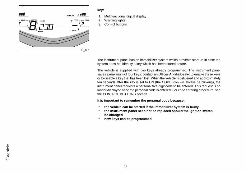
key:
1. Multifunctional digital display2. Warning lights3. Control buttons
The instrument panel has an immobilizer system which prevents start-up in case thesystem does not identify a key which has been stored before.
The vehicle is supplied with two keys already programmed. The instrument panelsaves a maximum of four keys: contact an Official Aprilia Dealer to enable these keysor to disable a key that has been lost. When the vehicle is delivered and approximatelyten seconds after the key is set to ON (the CODE icon will always be blinking), theinstrument panel requests a personal five-digit code to be entered. This request is nolonger displayed once the personal code is entered. For code entering procedure, seethe CONTROL BUTTONS section
It is important to remember the personal code because:
• the vehicle can be started if the immobilizer system is faulty• the instrument panel need not be replaced should the ignition switch
be changed• new keys can be programmed
28
2 Ve
hicl
e

02_08
Light unit (02_08)
key:
1. Turn indicator warning light (green)2. High beam warning light (blue)3. Low fuel warning light (orange)4. Cruise control warning light (green)5. Gear in neutral warning light (green)6. General warning light (red)7. ABS (Anti-lock Braking System) warning light (orange)8. ATC (Aprilia Traction Control) warning light (orange)
Digital lcd display (02_09, 02_10, 02_11, 02_12, 02_13, 02_14,02_15, 02_16, 02_17, 02_18, 02_19, 02_20, 02_21, 02_22, 02_23,02_24, 02_25, 02_26, 02_27)
The following indicators will light up for a couple of seconds on the instrument panelwhen the ignition key is set to "ON":
- all the warning lights;
- the backlighting turns off after the key is set to ON.
After two seconds, all instruments immediately show the current value of the meas-urements read.
NOTE
THE FUEL GAUGE LIGHT REQUIRES SOME TIME TO STABILIZE.
29
2 Vehicle
02_09
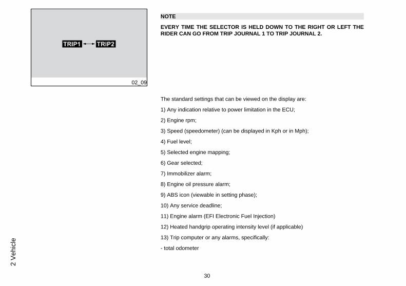
NOTE
EVERY TIME THE SELECTOR IS HELD DOWN TO THE RIGHT OR LEFT THERIDER CAN GO FROM TRIP JOURNAL 1 TO TRIP JOURNAL 2.
The standard settings that can be viewed on the display are:
1) Any indication relative to power limitation in the ECU;
2) Engine rpm;
3) Speed (speedometer) (can be displayed in Kph or in Mph);
4) Fuel level;
5) Selected engine mapping;
6) Gear selected;
7) Immobilizer alarm;
8) Engine oil pressure alarm;
9) ABS icon (viewable in setting phase);
10) Any service deadline;
11) Engine alarm (EFI Electronic Fuel Injection)
12) Heated handgrip operating intensity level (if applicable)
13) Trip computer or any alarms, specifically:
- total odometer
30
2 Ve
hicl
e

- Trip odometer
- Reserve travel
- Travelling time
- Average travelling speed
- Maximum saved speed
- Clock
14) ATC (Aprilia Traction Control)
15) ADD (Aprilia Dynamic Damping)
16) Water temperature
02_10
31
2 Vehicle
02_11
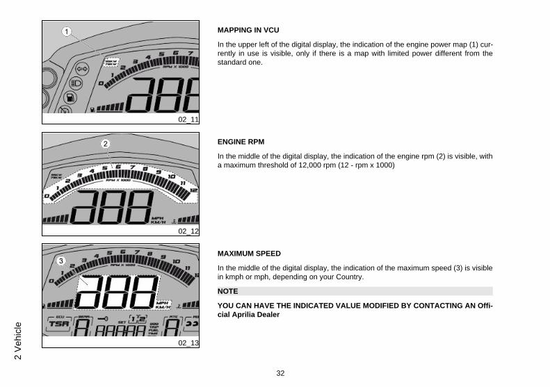
MAPPING IN VCU
In the upper left of the digital display, the indication of the engine power map (1) cur-rently in use is visible, only if there is a map with limited power different from thestandard one.
02_12
ENGINE RPM
In the middle of the digital display, the indication of the engine rpm (2) is visible, witha maximum threshold of 12,000 rpm (12 - rpm x 1000)
02_13
MAXIMUM SPEED
In the middle of the digital display, the indication of the maximum speed (3) is visiblein kmph or mph, depending on your Country.
NOTE
YOU CAN HAVE THE INDICATED VALUE MODIFIED BY CONTACTING AN Offi-cial Aprilia Dealer
32
2 Ve
hicl
e

02_14
FUEL LEVEL
On the digital display, center-left, the fuel level in the tank can be viewed through aseries of bars (4).
When the fuel level drops far enough for all bars to go off on the digital display, thefuel reserve warning light will turn on
CAUTION
THE DISTANCE TRAVELLED CORRESPONDING TO THE LAST FUEL INDICA-TOR BAR IS ABOUT THREE TIMES HIGHER THAN THE ONE OF THE OTHERBARS
02_15
Two kilometres (1.24 mi) after the low fuel warning light turns on, the kilometres trav-elled with low fuel are shown on the digital display.
NOTE
TO ENSURE A CORRECT READING, THE FUEL LOW INDICATION MAY BE DE-LAYED BY UP TO 60 SECONDS.
When the reserve fuel warning light is active, pressing a MODE control button willcause it to disappear and reappear 60 seconds later.
NOTE
THE FUEL LEVEL INDICATION MAY CHANGE DEPENDING ON THE INCLINA-TION OF THE MOTORCYCLE WHEN IT IS ON THE SIDE STAND AS OPPOSEDTO WHEN IT IS IN MOTION.
33
2 Vehicle

02_16
ENGINE MAP
In the left part of the digital display, the selected engine map (5) currently in use isvisible (TOURING / SPORT / RAIN).
02_17
GEAR ENGAGED
In the lower left of the digital display, the indication of the selected gear (6) currentlyin use can be viewed.
When the motorcycle is running idle, the symbol "0" will be displayed
02_18
ENGINE ALARM (EFI Electronic Fuel Injection)
If there is a system failure, the key symbol will be viewable in the middle of the display,or the request to enter the user code (7)
34
2 Ve
hicl
e

02_19
ENGINE OIL PRESSURE ALARM
If there is a failure of the motorcycle's lubrication system, the icon of the oil glass (8)will turn on in the middle of the digital display, to indicate the malfunction.
NOTE
WHEN THE ICON IS PERMANENTLY LIT, IT MEANS THERE IS AN ALARM DUETO THE OIL PRESSURE SENSOR
WHEN THE ICON IS BLINKING, IT MEANS THERE IS AN ALARM DUE TO AB-NORMAL OIL PRESSURE IN THE ENGINE
02_20
ABS
In the middle of the digital display there is an ABS icon (9) that will only be viewablewhen setting system parameters.
02_21
SERVICE THRESHOLD
When the thresholds of the maintenance intervals have been exceeded an adjustablespanner icon will appear (10) in the middle of the digital display.
This indicator may be reset once the scheduled service has been completed by anauthorised Aprilia Dealer or Service Centre.
35
2 Vehicle

02_22
HEATED HANDGRIPS
(if applicable)
If the heated handgrips are activated, the corresponding symbol (11) can be viewedin the middle of the digital display.
02_23
EFI
The wording EFI (Electronic Fuel Injection) (12) will appear in the middle of the digitaldisplay, should there be problem with the fuel injection.
02_24
TRAVEL COMPUTER
The travel computer (13) appears in the middle of the digital display to provide specificinformation on the distance travelled, speed and travelling time.
36
2 Ve
hicl
e

02_25
ATC (Aprilia Traction Control)
The Traction Control operating level (14) currently in use appears on the right side ofthe digital display.
02_26
ADD (Aprilia Dynamic Damping)
The level of the rear shock absorber (15) preload appears in the right side of the digitaldisplay, to show the selection made by the rider by way of certain symbols (helmetsand suitcases).
02_27
WATER TEMPERATURE
The running temperature of the cooling system (16) can be viewed in the right side ofthe digital display, indicated by a series of bars.
If the temperature rises to a level that is too high, the general warning light will alsoturn on.
37
2 Vehicle

Alarms (02_28, 02_29, 02_30)
In case of failure, a different icon is displayed according to the cause at the bottom ofthe display.
Take your vehicle as soon as possible to an Official Aprilia Dealer.
SERVICE ALARM
In case of failure found in the instrument panel or in the electronic control unit, theinstrument panel signals the failure by displaying the EFI icon and the red generalwarning light comes on.
02_28
URGENT SERVICE ALARM
The severe failure is signalled by the general warning light blinking and by the EFIicon that appears on the digital display. Take your vehicle as soon as possible to anOfficial Aprilia Dealer. In these cases, the control unit activates a safety procedurethat limits the vehicle performance so that the rider is able to reach an Official Apri-lia Dealer at low speed. According to the type of failure, performance can be limitedin two ways: a) by reducing the maximum torque produced; b) by keeping the engineat idle speed but slightly accelerated (during this operation, the throttle control is dis-abled).
If there is an immobilizer failure at ignition, the instrument panel requests you to entera user code. If the code is entered correctly, the instrument panel signals the failureby displaying the key icon and the red general warning light turns on.
38
2 Ve
hicl
e
02_29
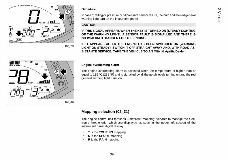
Oil failure
In case of failing oil pressure or oil pressure sensor failure, the bulb and the red generalwarning light turn on the instrument panel.
CAUTION
IF THIS SIGNAL APPEARS WHEN THE KEY IS TURNED ON (STEADY LIGHTINGOF THE WARNING LIGHT), A SENSOR FAULT IS SIGNALLED AND THERE ISNO IMMEDIATE DANGER FOR THE ENGINE.
IF IT APPEARS AFTER THE ENGINE HAS BEEN SWITCHED ON (WARNINGLIGHT ON STEADY), SWITCH IT OFF STRAIGHT AWAY AND, WITH ROAD AS-SISTANCE SERVICE, TAKE THE VEHICLE TO AN Official Aprilia Dealer.
02_30
Engine overheating alarm
The engine overheating alarm is activated when the temperature is higher than orequal to 115 °C (239 °F) and is signalled by all the notch levels turning on and the redgeneral warning light turns on.
Mapping selection (02_31)
The engine control unit foresees 3 different "mapping" variants to manage the elec-tronic throttle grip, which are displayed as seen in the upper left section of theinstrument panel digital display:
• T is the TOURING mapping• S is the SPORT mapping• R is the RAIN mapping
39
2 Vehicle

The TOURING mode has been thought for smooth tourist riding.
In the SPORT mode you get more acceleration; this variant has been thought for asporting use of the vehicle.
CAUTION
ONLY EXPERT RIDERS, RIDING ON ROADS WITH GOOD GRIP ARE ADVISEDTO USE THIS MODE. IT IS NOT RECOMMENDED FOR WET SURFACES AND/ORROADS WITH LOW GRIP.
02_31
The RAIN mode has been thought for riding on wet surfaces or roads with low grip.The system reduces the maximum torque supplied by the engine and smoothly de-livers it so as to prevent loss of grip. In this mode, the vehicle performance is limited,and therefore, the maximum speed cannot be reached.
EVEN IN THIS MODE, ALWAYS USE PARTICULAR CAUTION WHEN RIDING INPOOR GRIP CONDITIONS.
Push the starter button to go through the different mappings. Five seconds after theengine is started, this button can be used as a mapping selection button.
CAUTION
MAP SELECTION IS ONLY PERMITTED WITH THE ENGINE RUNNING AND THETHROTTLE RELEASED. MAP SELECTION IS ALSO POSSIBLE WITH THE MO-TORCYCLE IN MOTION, PROVIDED THAT THE THROTTLE GRIP IS RELEASED.
To change mappings, proceed as follows:
• press the button once and the symbol for the mapping currently being usedis shown blinking on the display
• press the button a second time, and within 1.5 seconds from the first pressing,the next mapping is selected and highlighted with the blinking frame on thedisplay. If more than 1.5 seconds elapse and the button is not pressed again(the next mapping is otherwise selected) and without twisting the throttle
40
2 Ve
hicl
e
control, the new mapping is highlighted with the frame lit steady on the dis-play. This means that the new mapping is applied for all practical purposes.
02_32
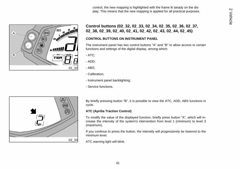
Control buttons (02_32, 02_33, 02_34, 02_35, 02_36, 02_37,02_38, 02_39, 02_40, 02_41, 02_42, 02_43, 02_44, 02_45)
CONTROL BUTTONS ON INSTRUMENT PANEL
The instrument panel has two control buttons "A" and "B" to allow access to certainfunctions and settings of the digital display, among which:
- ATC;
- ADD;
- ABS;
- Calibration;
- Instrument panel backlighting;
- Service functions.
02_33
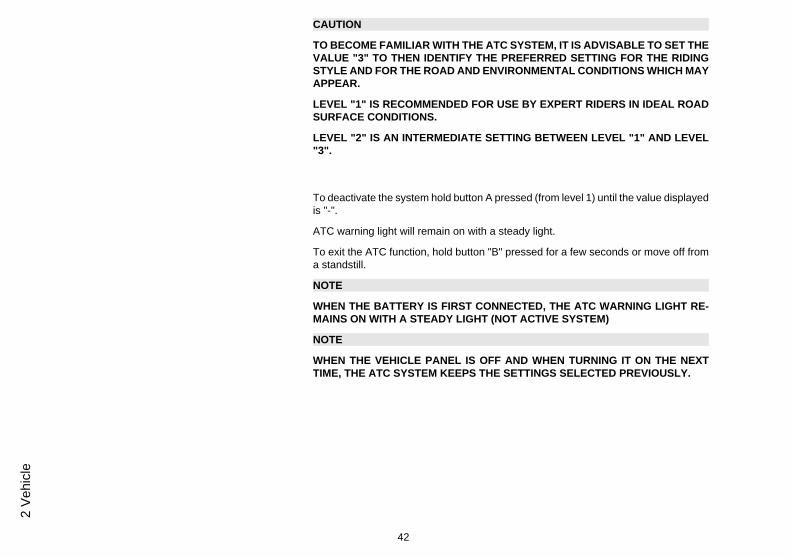
By briefly pressing button "B", it is possible to view the ATC, ADD, ABS functions incycle.
ATC (Aprilia Traction Control)
To modify the value of the displayed function, briefly press button "A", which will in-crease the intensity of the system's intervention from level 1 (minimum) to level 3(maximum).
If you continue to press the button, the intensity will progressively be lowered to theminimum level.
ATC warning light will blink.
41
2 Vehicle
CAUTION
TO BECOME FAMILIAR WITH THE ATC SYSTEM, IT IS ADVISABLE TO SET THEVALUE "3" TO THEN IDENTIFY THE PREFERRED SETTING FOR THE RIDINGSTYLE AND FOR THE ROAD AND ENVIRONMENTAL CONDITIONS WHICH MAYAPPEAR.
LEVEL "1" IS RECOMMENDED FOR USE BY EXPERT RIDERS IN IDEAL ROADSURFACE CONDITIONS.
LEVEL "2" IS AN INTERMEDIATE SETTING BETWEEN LEVEL "1" AND LEVEL"3".
To deactivate the system hold button A pressed (from level 1) until the value displayedis "-".
ATC warning light will remain on with a steady light.
To exit the ATC function, hold button "B" pressed for a few seconds or move off froma standstill.
NOTE
WHEN THE BATTERY IS FIRST CONNECTED, THE ATC WARNING LIGHT RE-MAINS ON WITH A STEADY LIGHT (NOT ACTIVE SYSTEM)
NOTE
WHEN THE VEHICLE PANEL IS OFF AND WHEN TURNING IT ON THE NEXTTIME, THE ATC SYSTEM KEEPS THE SETTINGS SELECTED PREVIOUSLY.
42
2 Ve
hicl
e

02_34
ADD (Aprilia Dynamic Damping)
To modify the value of the preload function displayed, briefly press button "A", whichwill modify the type of intervention according to the driver's needs.
The system is identified by a series of symbols that correspond to a certain type ofspecific setting:
- The helmet corresponds to the preload setting with only the driver on board
- The helmet and suitcase corresponds to the preload setting with the driver and lug-gage
- Two helmets correspond to the preload setting with driver and passenger
- Two helmets and a suitcase correspond to the preload setting with driver, passengerand luggage
- Two helmets and a suitcase blinking in sequence correspond to the preload settingin automatic mode
NOTE
WITH THE MOTORCYCLE'S INSTRUMENT PANEL SWITCHED OFF, AT THENEXT IGNITION OF THE SYSTEM THE ADD KEEPS THE SETTINGS CHOSENPREVIOUSLY.
02_35
ABS
To activate or deactivate the system, briefly press button "A", which will either activateor deactivate the system in cycles.
If the system is activated, the ABS warning light will blink
43
2 Vehicle

02_36
If the system is deactivated, the ABS warning light will stay permanently on.
In both cases, to confirm the selected mode, hold button "B" pressed for a few sec-onds.
The function will automatically appear after 5 seconds, if the selection is not madepromptly, or when the motorcycle is running.
NOTE
AT KEY ON, IF THE SYSTEM IS FUNCTIONING CORRECTLY, THE ABS INDICA-TOR LIGHT WILL BLINK (ONCE A VEHICLE SPEED OF 5 Km/h - 3.1 mph ISEXCEEDED, THE SYSTEM WILL ONLY BE ACTIVE IF THE WARNING LIGHTGOES OFF)
NOTE
WHEN THE BIKE'S PANEL IS OFF AND WHEN TURNING IT ON THE NEXT TIMETHE ABS SYSTEM IS STILL ACTIVE, REGARDLESS OF WHAT WAS SET PRE-VIOUSLY.
02_37
CALIBRATION
To access the CALIBRATION function, simultaneously hold buttons "A" and "B"pressed for a few seconds.
When the function is activated (with vehicle at a standstill), the following wording willappear on the screen page of the display:
CAL
The high beam light will start to blink fast.
To calibrate the ATC (Aprilia Traction Control) system, ride for approximately 10 sec-onds in a straight line on a flat section of road in second gear and at a speed of 30 +/-2 Km/h (18.64 +/- 1.24 mph), until the message CAL is no longer shown on the displayand the light turns off.
44
2 Ve
hicl
e

NOTE
ONCE THE WORD CALIBRATION DISAPPEARS FROM THE DISPLAY, TO COM-PLETE THE CALIBRATION PROCEDURE, STOP THE VEHICLE AND SHUT OFFTHE PANEL FOR AT LEAST 30 SECONDS.
THIS ALLOWS THE CALIBRATION TO BE STORED IN THE MEMORY.
NOTE
CARRY OUT THE CALIBRATION EACH TIME TYRES TYPE OR DRIVE GEAR-MODE IS CHANGED.
NOTE
TURN THE IGNITION SWITCH OFF TO ABORT THE CALIBRATION PROCE-DURE.
DURING CALIBRATION, ATC IS AUTOMATICALLY DEACTIVATED (IF PREVI-OUSLY ACTIVATED).
02_38
BACKLIGHTING
To modify the intensity of the digital display's backlighting, hold button "B" pressed fora few seconds, to access the adjustments screen page.
Whenever button "A" is briefly pressed,, backlighting intensity (indicated by a numberon the digital display) increases up to a maximum of 5 levels.The function is cyclical, which means that once the maximum value is reached, ifbutton "A" is pressed again, the backlighting will restart from the minimum value.
45
2 Vehicle
To quit the function, hold button "B" pressed for a few seconds; the function will au-tomatically quit after 5 seconds.
02_39
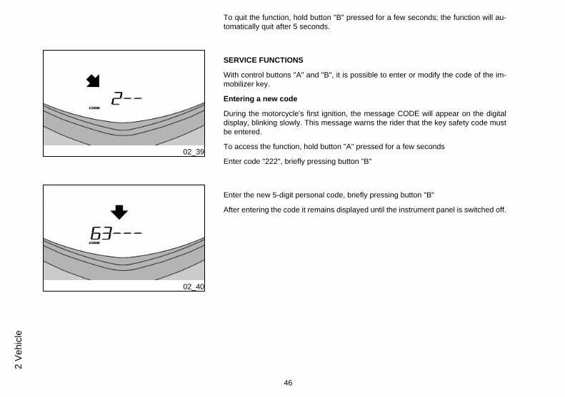
SERVICE FUNCTIONS
With control buttons "A" and "B", it is possible to enter or modify the code of the im-mobilizer key.
Entering a new code
During the motorcycle's first ignition, the message CODE will appear on the digitaldisplay, blinking slowly. This message warns the rider that the key safety code mustbe entered.
To access the function, hold button "A" pressed for a few seconds
Enter code "222", briefly pressing button "B"
02_40
Enter the new 5-digit personal code, briefly pressing button "B"
After entering the code it remains displayed until the instrument panel is switched off.
46
2 Ve
hicl
e
02_41
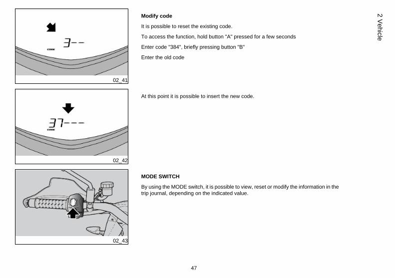
Modify code
It is possible to reset the existing code.
To access the function, hold button "A" pressed for a few seconds
Enter code "384", briefly pressing button "B"
Enter the old code
02_42
At this point it is possible to insert the new code.
02_43
MODE SWITCH
By using the MODE switch, it is possible to view, reset or modify the information in thetrip journal, depending on the indicated value.
47
2 Vehicle

02_44
Trip journal 1 and 2
Two trip journals are available (*).
02_45
Press and hold down the MODE control to the left to select the TRIP JOURNAL 1;icon "1" on the DIGITAL DISPLAY turns on.
Press and hold down the MODE control to the right to select the TRIP JOURNAL 2;icon "2" on the DIGITAL DISPLAY turns on.
In both journals, each time the MODE control is pressed briefly to the right or left, thefollowing information is displayed in sequence (**):
ODOMETER (1)
TRIP ODOMETER (2)
TRAVELLING TIME (3)
AVERAGE SPEED (4)
MAXIMUM SPEED (5)
CLOCK (6)
With the following options: PARTIAL ODOMETER, TRAVELLING TIME, MAXIMUMSPEED; holding the central button down resets all the saved values in the active TRIPJOURNAL.
CLOCK
48
2 Ve
hicl
e

To adjust the clock, the TRIP1 or TRIP2 menu must be scrolled until the function isreached.
When pressing the MODE selector for a few seconds, you enter this mode, the minutesof the clock disappear and only the hours remain. Each time the MODE selector ispressed to the right, the hour value increases; likewise, each time the MODE selectoris pressed to the left, the hour value decreases. Press the MODE selector central partto store the set value and to shift to minute adjustment.The minute indicator is no longer displayed when this function is activated; only thehour indicator is shown. Each time the MODE selector is pressed to the right, theminute value increases; likewise, each time the MODE selector is pressed to the leftthe minute value decreases.Press the MODE selector central part to store the set value and to exit the clock ad-justment function.
02_46
Ignition switch (02_46)
The ignition switch (1) is located at the front of the fuel reservoir.
The vehicle is supplied with two keys (one is the spare key).
The lights go off when the ignition switch is set to «OFF».
NOTE
THE KEY ACTIVATES THE IGNITION SWITCH AND OPERATES THE STEERINGLOCK.
NOTE
THE LIGHTS TURN ON AUTOMATICALLY UPON ENGINE START-UP.
LOCK (1): The steering is locked. It is not possible to start the engine or switch on thelights. The key can be extracted
49
2 Vehicle

OFF (2): The engine and lights cannot be set to work. The key can be extracted.
ON (3): the engine may be started. The key cannot be extracted.
Locking the steering wheel
To lock the steering:
• Turn the handlebar completely to the left.
• Turn the key to «OFF».
• Push in the key and turn it anticlockwise (to the left), steer the handlebar slowly untilthe key is set to «LOCK».
• Remove the key.
CAUTION
TO AVOID LOSING CONTROL OF THE VEHICLE, NEVER TURN THE KEY TO"LOCK" WHILE RIDING.
Horn button (02_47)
NOTE
ELECTRICAL COMPONENTS FUNCTION ONLY WHEN THE IGNITION KEY ISSET TO "ON"
50
2 Ve
hicl
e

02_47
Press it to activate the horn.
02_48
Switch direction indicators (02_48)
Move the switch to the left, to indicate a left turn; move the switch to the right to indicatea right turn. Pressing the switch deactivates the turn indicator.
CAUTION
IF THE WARNING LIGHT WITH ARROWS FLASHES QUICKLY, IT MEANS THATONE OR BOTH TURN SIGNALS LIGHT BULBS ARE BURNT OUT.
The turn indicators have a self-cancelling function that implements the following logic.
With the vehicle at a standstill (speed = zero), the turn indicators continue flashingindefinitely.
With the vehicle in motion, the turn signals self-cancel when one the two followingconditions is met:
• After a time (t) = 40 sec.• After riding 500 m (0.31 mi).
51
2 Vehicle
If the vehicle speed reaches zero during this period, the time and distance counts arereset and start again from zero when the vehicle starts moving once again.
Switching on the opposite side turn indicators without pressing the switch in the in-termediate reset position causes both the time and distance counters to reset andrecommence from zero.
02_49
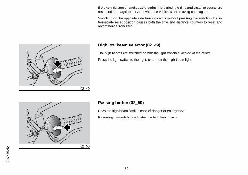
High/low beam selector (02_49)
The high beams are switched on with the light switches located at the centre.
Press the light switch to the right, to turn on the high beam light;
02_50
Passing button (02_50)
Uses the high beam flash in case of danger or emergency.
Releasing the switch deactivates the high beam flash.
52
2 Ve
hicl
e

Heated handgrip control (02_51, 02_52)
(IF AVAILABLE)
02_51
Activation, deactivation and heat level of the handgrips take place by short pressingthe control.
02_52
There are 3 heat intensity levels which are activated cyclically from level 1 (minimum)to level 3 (maximum) each time the control is pressed. After level 3, pressing thecontrol again deactivates the function.
If the key is switched to the OFF position, upon restarting the function will be deacti-vated.
NOTE
THE HANDGRIPS ARE HEATED ONLY WHEN THE ENGINE IS RUNNING ANDABOVE 2000 RPM, REGARDLESS OF THE SELECTED INTENSITY LEVEL.
53
2 Vehicle

02_53
Start-up button (02_53)
Press the button and the starter motor spins the engine.
CAUTION
FIVE SECONDS AFTER THE ENGINE IS STARTED, THIS BUTTON CAN BE USEDAS "MAPPING SELECTION" BUTTON.
02_54
Engine stop switch (02_54)
It acts as an engine cut-off or emergency stop switch.
Press this switch to stop the engine.
Button Cruise Control (02_55, 02_56)
(IF APPLICABLE)
• Cruise control is an electronic system which keeps the vehicle at the speedselected by the rider
54
2 Ve
hicl
e

• To activate the function (switching from OFF to ON), press and hold theCruise Control button for approximately 2 seconds
• If the system is on this will be indicated by a flashing warning light on theinstrument panel
The system can be used in a specific speed range, only for third through sixth gear,even while decelerating with the throttle grip closed, as defined in the table below:
SYSTEM ACTIVATION SPEEDSPEED 3rd 4th 5th 6th
MIN Speed 50 km/h (31.07mph)
60 km/h (37.28mph)
65 km/h (40.39mph)
70 km/h (43.50mph)
MAX Speed 100 km/h (62.14MPH)
120 km/h (74.56MPH)
160 km/h (99.42MPH)
180 km/h(111.85 MPH)
02_55
55
2 Vehicle

02_56
Once the desired speed is reached, the system may be activated (SET state) bypressing the cruise control button briefly, provided that the following conditions aremet:
- The engaged gear must not be lower than third and cannot be neutral:
- The brakes must not be applied:
- The clutch lever must not be in use:
The instrument panel indicator lamp lights continuously to indicate that the system isactive.
The throttle grip may now be released, and the cruise control function will autono-mously maintain the selected speed.
The accelerator can be used to temporarily increase speed, up to a maximum 30 km/h (18.64 mi) more than the selected speed, without deactivating the system (e.g.overtake).
If the speed is increased by more than 30 km/h (18.64 mi), the system will be deacti-vated (status changes from SET to ON).
When throttle is released, the motorcycle will return to the selected cruising speed. Byexceeding the maximum threshold set for each gear in the previous table, the systemwill be deactivated (status changes from SET to ON).
Besides, the system deactivates (going from SET to ON status, flashing warning light)in the event of one of the following conditions:
- Engaging the clutch;
- Engaging the front/rear brake;
- Downshifting to gear 3 or putting the gearbox in neutral;
- Press the Cruise Control button with a short press;
56
2 Ve
hicl
e

- If the engine RPM limiter intervenes;
- If traction control intervenes;
- If the motorcycle negotiates a particularly steep uphill or downhill gradient.
The system switches off completely (switching from SET to OFF state), the storedspeed setting is cancelled and the relative instrument panel indicator lamp extinguish-es in any of the following conditions:
- Cruise Control button pressed and held;
- Run-OFF switch activated;
- Engine switch off (key-OFF).
In case of error.
System ABS
The ABS system is a device that prevents wheel locking in case of an emergencybraking, thus increasing vehicle stability when braking, compared with a conventionalbraking system.
The ABS system enhances control over the vehicle, taking into consideration neverto exceed the physical limits of vehicle grip on the road. The rider is fully responsiblefor riding at a suitable speed based on weather and road conditions, always leavingan appropriate safety margin.
Under no circumstances can the ABS system compensate for the rider's misjudge-ment or improper use of brakes.
NOTE
WHEN THE ABS SYSTEM STARTS WORKING, A VIBRATION IS FELT ON THEBRAKE LEVER.
57
2 Vehicle

THE ANTILOCK BRAKING SYSTEM OF THE WHEEL DOES NOT PREVENTFALLS WHILE CORNERING.
AN EMERGENCY BRAKING WITH THE VEHICLE INCLINED, HANDLEBARTURNED, ON UNEVEN OR SLIPPERY ROADS, OR WITH POOR GRIP, CREATESA LACK OF STABILITY DIFFICULT TO HANDLE. RIDE CAREFULLY AND SEN-SIBLY AND ALWAYS BRAKE GRADUALLY.
DO NOT SPEED RECKLESSLY. THE VEHICLE GRIP ON THE ROAD IS SUBJECTTO LAWS OF PHYSICS WHICH NOT EVEN THE ABS SYSTEM CAN ELIMINATE.
Upon starting the vehicle, after the initial instrument panel check, the ABS warninglight flashes until a speed of 5 kph (3.1 mph) is exceeded and then it switches off orcontinues to flash even after exceeding the speed of 5 kph (3.1 mph).
If the ABS warning light continues flashing or is permanently on, a failure has beendetected and the ABS has been automatically deactivated.
In this case carry out the following operations:
- stop the vehicle;
- key OFF-ON;
- ride over 5 km/h (3.1 mph): the ABS warning light must be turned off;
- the ABS system is working.
If the ABS disabled indication remains:
NOTE
SHOULD THIS OCCUR, CONTACT AN aprilia Official Dealer.
58
2 Ve
hicl
e

NOTE
THE ABS SYSTEM HAS BEEN DESIGNED AND DEVELOPED, CONSISTENTLYWITH THE REST OF THE VEHICLE, TO BE USED ON TARMAC ROADS AND ITIS NOT SUITABLE FOR OFF-ROAD USE.
IF THE VEHICLE IS USED ON UNSURFACED AND/OR SPECIFICALLY ROUGHROADS, THE ABS SYSTEM MAY GET DISABLED AUTOMATICALLY; IN ANYCASE, THE BRAKING SYSTEM WORKS PERFECTLY WELL AS A TRADITIONALNON-ABS BRAKING SYSTEM AND PROVIDES A STANDARD STOP CAPACITY.
IN ORDER TO REACTIVATE THE SYSTEM JUST SHUT OFF AND START THEVEHICLE UP AGAIN AND RIDE OVER 5 km/h (3.1 mph).
THE ABS SYSTEM ACTS ON BOTH THE FRONT AND REAR WHEELS BY OB-TAINING INFORMATION FROM THE ROTATION/ LOCKING TONE WHEELS.ALWAYS CHECK THAT THE TONE WHEEL IS CLEAN, AND REGULARLYCHECK THAT THE DISTANCE FROM THE SENSOR IS CONSTANT ON ALL 360GRADES. SHOULD THE WHEELS BE REMOVED AND REFITTED, IT IS VERYIMPORTANT TO CHECK THAT THE DISTANCE BETWEEN TONE WHEEL ANDSENSOR IS THE ONE SPECIFIED. FOR CHECKING AND ADJUSTMENT, CON-TACT AN Authorised APRILIA Workshop.
IN THE CASE OF A MOTORCYCLE WITH THE ABS SYSTEM, BRAKE PADS WITHFRICTION MATERIALS THAT ARE NOT TYPE APPROVED WILL JEOPARDISEBRAKING, DRASTICALLY REDUCING RIDING SAFETY.
NOTE
THE SYSTEM SENSORS WITH A SIGNIFICANT ACCURACY IN READING THETONE WHEELS CAN GENERATE, WITH THE MOTORCYCLE AT A STANDSTILL
59
2 Vehicle
AND ENGINE ON, A SPEED INDICATION OF A FEW km / h (mi) IN THE DIGITALDISPLAY.
SUCH BEHAVIOUR IS TO BE CONSIDERED NORMAL AND DOES NOT CREATEMALFUNCTIONS IN THE SYSTEM.
IF THE GAP FOR ONE OR BOTH SENSORS IS NOT WITHIN THE TOLERANCEINDICATED BELOW, TAKE THE MOTORCYCLE TO AN official Aprilia DEALER-SHIP
CharacteristicDistance between tone wheel and front sensor
0.3 - 2.00 mm (0.012 - 0.079 in)
Distance between tone wheel and rear sensor
0.3 - 2.00 mm (0.012 - 0.079 in)
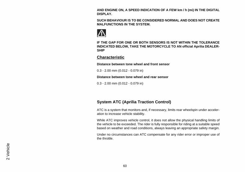
System ATC (Aprilia Traction Control)
ATC is a system that monitors and, if necessary, limits rear wheelspin under acceler-ation to increase vehicle stability.
While ATC improves vehicle control, it does not allow the physical handling limits ofthe vehicle to be exceeded. The rider is fully responsible for riding at a suitable speedbased on weather and road conditions, always leaving an appropriate safety margin.
Under no circumstances can ATC compensate for any rider error or improper use ofthe throttle.
60
2 Ve
hicl
e

THE TRACTION CONTROL SYSTEM CANNOT PREVENT FALLS WHILE COR-NERING.
ACCELERATING SUDDENLY WHILE THE VEHICLE IS INCLINED OR WITH THEHANDLEBARS TURNED WILL PUT THE VEHICLE IN AN UNSTABLE STATETHAT IS EXTREMELY DIFFICULT TO RECTIFY.
DO NOT SPEED RECKLESSLY. LIMITS OF GRIP ARE DETERMINED BY LAWSOF PHYSICS WHICH EVEN THE ATC SYSTEM CANNOT OVERCOME.
WARNING AND INDICATOR LIGHTS, KEY
- Indicator light off: a system active after exceeding 5 km/h (3.1 mph) after switchingon the panel;
- Indicator light continuously lit: with the system deactivated on purpose or if thereis a malfunction;
- Indicator light flashing slowly: with system active after key-on before exceeding5 Km/h (3.1 mph) or in the event of certain malfunctions causing the ATC level to belocked (ATC settings no longer modifiable);
- Indicator light flashing quickly: when the system intervenes effectively on thetraction control.
ATC SYSTEM DEACTIVATED MANUALLY
When starting the vehicle, after the instrument panel initial check cycle, if the systemis deactivated, the ATC warning light remains lit until the rider decides to activate thesystem.
ATC SYSTEM ACTIVE
When starting the vehicle, after the instrument panel initial check cycle, the ATCwarning light flashes if the system was active at the previous key-off (and is therefore
61
2 Vehicle
still active) and continues flashing until vehicle speed exceeds 5 km/h (3.1 mph), afterwhich it extinguishes.
If the ATC warning light is permanently on, a failure has been detected and the ATChas been automatically deactivated.
In this case carry out the following operations:
- stop the vehicle;
- key OFF-ON;
- reactivate the system manually
- ride over 5 km/h (3.1 mph): the ATC warning light must be turned off;
- ATC system working correctly.
If the 'ATC system deactivated' indication persists:
NOTE
SHOULD THIS OCCUR, CONTACT AN aprilia Official Dealer.
THE ATC SYSTEM ACTS ON REAR WHEEL BY OBTAINING INFORMATIONFROM THE ROTATION/LOCKING TONE WHEELS FITTED ON BOTH WHEELS.ALWAYS CHECK THAT THE TONE WHEELS ARE CLEAN, AND REGULARLYCHECK THAT THE GAP BETWEEN THE TONE WHEEL AND THE SENSOR ISCONSTANT AROUND THE ENTIRE CIRCUMFERENCE OF THE TONE WHEELITSELF. SHOULD THE WHEELS BE REMOVED AND REFITTED, IT IS VERY IM-PORTANT TO CHECK THAT THE DISTANCE BETWEEN TONE WHEEL ANDSENSOR IS THE ONE SPECIFIED. FOR CHECKING AND ADJUSTMENT, CON-TACT AN Authorised APRILIA Workshop.
62
2 Ve
hicl
e

NOTE
IN CASE OF PROLONGED ROTATION OF THE REAR WHEEL WITH THE FRONTWHEEL LOCKED (BURNOUT, VEHICLE PLACED ON CENTRAL STAND, ETC.)THE SYSTEM CAN BE DEACTIVATED AUTOMATICALLY WITH ATC WARNINGLIGHT FIXED ON.
TO REACTIVATE, TURN THE IGNITION SWITCH OFF AND THEN ON AGAIN ANDSELECT THE REQUIRED SETTING.
NOTE
THE SYSTEM SENSORS WITH A SIGNIFICANT ACCURACY IN READING THETONE WHEELS CAN GENERATE, WITH THE MOTORCYCLE AT A STANDSTILLAND ENGINE ON, A SPEED INDICATION OF A FEW km / h (mi) IN THE DIGITALDISPLAY.
SUCH BEHAVIOUR IS TO BE CONSIDERED NORMAL AND DOES NOT CREATEMALFUNCTIONS IN THE SYSTEM.
CharacteristicDistance between tone wheel and front sensor
0.3 - 2.00 mm (0.012 - 0.079 in)
Distance between tone wheel and rear sensor
0.3 - 2.00 mm (0.012 - 0.079 in)
ADD system (Aprilia Dynamic Damping)
ADD (Aprilia Dynamic Damping) is an integrated system that controls the semi-activesuspensions and electrically operated preload of the rear shock absorber only.
The system adjusts the fork and shock absorber damping in real time, to provide thebest riding comfort and maintain motorcycle trim as steady as possible during the ride.
63
2 Vehicle

The system works independently via a dedicated ECU; no adjustments are necessary,except for the preload of the rear single shock absorber.
With the motorcycle off, the suspensions are rigid, because they are not being oper-ated.
The preload of the rear shock absorber can be manually adjusted on four levels, plusa fifth so-called automatic one. With key-on, the level set on the instrument panelbefore the last key-off is maintained. The automatic level is highlighted on the displayof the instrument panel by symbols, a helmet and suitcase that slowly scroll in se-quence.
The automatic level independently adjusts the preload based on the vehicle load, soas to maintain the height steady as much as possible.
The system works in two phases:
1) With the vehicle at a standstill, the engine running, gear in idle, crutch closed, thesystem performs a first overall preload adjustment if certain signal constance condi-tions are met.
2) With the vehicle moving, the system continuously monitors various signals comingfrom the vehicle and if certain signal constance conditions are met, it acts on thepreload to find the ideal position.
If the system has already reached the ideal position, it will make no further adjust-ments.
An automatic adjustment of the preload is highlighted on the digital display by symbols,a helmet and suitcase, that scroll quickly in sequence, to then return to slow scrollingwhen the system has completed the adjustment.
Depending on the type of fault, the suspensions may work in either medium or maxi-mum damping.
64
2 Ve
hicl
e

If there is a failure in the ADD system, the two helmets and the suitcase blink togetheron the display of the instrument panel, and the red GENERAL WARNING light stayspermanently on. Depending on the type of fault, the suspensions may work in eithermedium rigidity or become fully rigid.
WARNING
IN THE EVENT OF FAULT, FOR SAFETY REASONS, SLOW DOWN THE VEHICLE
DUE TO ELECTRICAL CONSUMPTION REASONS, THE ELECTRICAL PRELOADONLY WORKS WITH THE ENGINE RUNNING (LEVEL ADJUSTMENT IS LOCKEDWHILE THE ENGINE IS OFF). IF THE ENGINE IS NOT STARTED WITHIN 15 SEC-ONDS FROM KEY-ON, THE ELECTRONIC SUSPENSIONS ARE FOR THE SAMEREASONS TURNED OFF (AND THEREFORE LEAD TO MAXIMUM DAMPING)AND ARE REACTIVATED WHEN THE ENGINE IS ACTUALLY STARTED.
02_57
Immobilizer system operation (02_57)
For enhanced theft protection, the vehicle is equipped with an electronic immobilizersystem that is activated automatically when the ignition key is removed.
Keep the second key in a safe place since it is not possible to make a copy if it getslost. This would imply replacing numerous parts of the vehicle (besides the locks).
Each key in the grip has an electronic device - transponder - which modulates theradio frequency signal emitted by a special built-in aerial in the switch when the vehicleis started.
The modulated signal is the "password" by which the appropriate central unit recog-nises the key and only after this occurs, it allows the engine start-up.
CAUTION
THE IMMOBILIZER SYSTEM CAN MEMORISE UP TO FOUR KEYS.
DATA STORAGE OPERATION CAN ONLY BE PERFORMED AT THE DEALER'S.
65
2 Vehicle

DATA STORAGE PROCEDURE CANCELS THE EXISTING CODES. THEREFORE,IF A CUSTOMER WANTS TO PROGRAM SOME NEW KEYS, S/HE SHOULD GOTO THE DEALER TAKING ALL THE KEYS S/HE WANTS TO ENABLE.
With the ignition key OFF, immobilizer operation mode is indicated by a warning light(1) placed on the instrument panel
The light goes off after 50 h
02_58
Opening the saddle (02_58, 02_59)
• Rest the vehicle on its stand.• Insert the key (1) in the lock located on the left fairing.• Turn the key (1) clockwise and remove the passenger saddle (2).
There is a useful document compartment in the vehicle tail fairing. Remove the pas-senger saddle (2) to reach it.
02_59
To lock the saddle (2):
• Move the passenger saddle (2) to fasten the front retainers correctly.• Push the back of the passenger saddle (2), where the rear retainers are, to
trip the lock.
CAUTION
BEFORE LOWERING AND LOCKING THE SADDLE, CHECK THAT THE KEY HASNOT BEEN LEFT IN THE GLOVEBOX / TOOL KIT COMPARTMENT.
66
2 Ve
hicl
e

BEFORE SETTING OFF, MAKE SURE THAT THE SADDLE IS CORRECTLYLOCKED INTO POSITION.
02_60
Glove/tool kit compartment (02_60)
Remove the passenger saddle to have access to the glove-box / toolkit compartment.
02_61
USB Port (02_61, 02_62, 02_63)
There is USB port in the glove-box/toolkit.
To use it, remove the cover and the protective plug.
TO AVOID THAT WATER AND/OR HUMIDITY CAN DAMAGE THE USB PORT,USE THE PROTECTIVE COVER, EVEN WHEN A DEVICE IS CONNECTED.
THE INCLUDED USB PORT IS COMPATIBLE WITH DEVICES OF THE FOLLOW-ING BRANDS: Apple iPhone, Apple iPod, Apple iPod Nano, Apple iPod Touch,
67
2 Vehicle

Blackberry Pearl, Blackberry 8xxx IT IS NOT COMPATIBLE WITH DEVICES FORMOTOROLA PRODUCTS.
02_62
IF A USB DEVICE IS CONNECTED, ENSURE THE CORRECT POSITIONING OFTHE CABLE TO AVOID THAT IT WILL BE SMASHED.
02_63
To remove the cover, press the locking tongue.
The USB port is activated once the key is turned to position «ON».
WARNING
PROLONGED USE OF THE PLUG SOCKET MAY RESULT IN PARTIAL DIS-CHARGE OF THE BATTERY
68
2 Ve
hicl
e

USB PORT
Output voltage (5.00+/-0.25) DC
Charge current 1A Max
Identification (02_64, 02_65)
Write down the chassis and engine number in the specific space in this booklet. Thechassis number is handy when purchasing spare parts.
CAUTION
THE MODIFICATION OF THE IDENTIFICATION CODES IS A SERIOUS PUNISH-ABLE CRIME. HOWEVER, THE LIMITED WARRANTY FOR NEW VEHICLES WILLBE VOID IF THE VEHICLE IDENTIFICATION NUMBER (VIN) HAS BEEN MODI-FIED OR NOT PROMPTLY DETERMINED.
02_64
CHASSIS NUMBERThe chassis number is stamped on the right side of the headstock.
Chassis No. ....................
69
2 Vehicle

02_65
ENGINE NUMBER
The engine number is printed on the base of the engine crankcase, left hand side.
Engine No. ....................
02_66
Adjusting the windscreen (02_66)
It is possible to adjust the windscreen manually as follows:
• upholding the windscreen and working on both its sides, loosen the twoknobs.
• adjust the windscreen to the desired position.• upholding the windscreen and working on both its sides, tighten the two
knobs.
Provision for the installation of accessories (02_67, 02_68,02_69, 02_70, 02_71, 02_72)
SIDE PANNIERS
(if applicable)
70
2 Ve
hicl
e

DO NOT LOAD MORE THAN 5 kg (11.02 lb) FOR EACH BAG, AN EXCESSIVELOAD COULD DAMAGE IT
COVER OPENING
• Rest the vehicle on its stand.• Introduce the key (1) in the pannier cover handle (2).• Turn the key (1) anticlockwise.
02_67
• Lift the handle (2) and free it from the cover (3).• Open the cover (3).
71
2 Vehicle

02_68
02_69
REMOVAL
• Lift the safety stopper
02_70
• Introduce the key (1) in the pannier cover handle (2). Turn the key (1) anti-clockwise.
• Pull the pannier and free it from the stopper• Lift it and unthread it from the fixing hooks
72
2 Ve
hicl
e

02_71
73
2 Vehicle

74
2 Ve
hicl
e

CAPONORD
Chap. 03Use
75

Checks (03_01)
CAUTION
BEFORE RIDING, ALWAYS PERFORM A PRELIMINARY CHECK OF THE VEHI-CLE TO ENSURE CORRECT AND SAFE OPERATION. FAILURE TO DO SO MAYLEAD TO SERIOUS PERSONAL INJURY OR DAMAGE TO THE VEHICLE. DONOT HESITATE TO CONTACT AN OFFICIAL Aprilia DEALER IF YOU DO NOTUNDERSTAND HOW SOME CONTROLS WORK OR IF A MALFUNCTION IS DE-TECTED OR SUSPECTED. CHECKING TAKES VERY LITTLE TIME BUT CON-SIDERABLY INCREASES SAFETY.
CAUTION
ACCORDING TO THE TIME ELAPSED FROM THE MOMENT THE KEY IS SET TO"KEY ON" UNTIL THE ENGINE STARTS, THE STOP LIGHT CAN BE ACTIVATEDFOR ABOUT HALF A SECOND OR NOT.
03_01
This vehicle has been programmed to indicate in real time any operation failure storedin the electronic control unit memory.
Every time the ignition switch is turned to "KEY ON", the alarm LED warning light turnson for about three seconds on the instrument panel.
76
3 U
se

PRE-RIDE CHECKS
Front and rear disc brake Check for proper operation. Checkbrake lever empty travel and brakefluid level. Check for leaks. Checkbrake pads for wear. If necessarytop-up with brake fluid.
Throttle grip Check that the throttle functionssmoothly and can be fully openedand closed in all steering positions.Adjust and/or lubricate ifnecessary.
Engine oil Check and/or top-up as required.
Wheels/ tyres Check that tyres are in goodconditions. Check inflationpressure, tyre wear and potentialdamage.
Remove any possible strangebody that might be stuck in thetread design.
Brake levers Check they function smoothly.
Lubricate the joints and adjust thetravel if necessary.
Clutch Check for proper operation. Checkclutch lever free play and fluidlevel. Check for leaks. Top-up thefluid if necessary; the clutch mustwork without gripping and/orsliding.
77
3 Use

Steering Check that the rotation is uniform,smooth and there are no signs ofclearance or slackness.
Side stand / Centre stand (if fitted) Check it works properly. Checkthat there is no resistance when theside stand is pulled up and downand that the spring tension makesit snap back to its rest position.
Lubricate couplings and joints ifnecessary.
Check the safety switch for correctoperation.
Clamping elements Check that the clamping elementsare not loose.
Adjust or tighten them as required.
Drive chain Check it for backlash.
Fuel tank Check the coolant level and refill ifnecessary.
Check the circuit for leaks orobstructions.
Check that the tank cap closescorrectly.
Coolant Fluid level inside the expansiontank should be between the'FULL' and 'LOW' referencemarks.
Engine stop switch (ON - OFF) Check function.
78
3 U
se

Lights, warning lights, horn, rearstop light switch and electricaldevices
Check function of horn and lights.Replace bulbs or repair any faultsnoted.
Tone wheels Check that the tone wheels areperfectly clean and in goodconditions.
03_02
Refuelling (03_02)
To refuel:
• Lift the cover (1).• Introduce the key (2) in the fuel tank cap lock (3).• Turn the key clockwise, pull and open the fuel tank lid.
CharacteristicFuel tank (reserve included)
24 l (5.28 UK gal; 6.34 US gal)
Fuel reserve
4 l (0.88 UK gal; 1.06 US gal)
• Refuel.
CAUTION
DO NOT ADD ADDITIVES OR ANY OTHER SUBSTANCES TO THE FUEL.
79
3 Use

WHEN USING A FUNNEL, ENSURE THAT IT IS PERFECTLY CLEAN.
WHEN FILLING THE TANK COMPLETELY, DO NOT FILL BEYOND THE LOWEREDGE OF THE RECESS (SEE FIGURE).
DURING THE REFUELLING, AVOID FUEL LEAKAGE WHICH MAY CAUSE DAM-AGE TO OBJECTS AND/OR PERSONAL INJURIES AND FIRE HAZARD.
DURING REFUELLING, AVOID THE USE OF ELECTRIC DEVICES AND/OR MO-BILE PHONES, BECAUSE FUEL VAPOURS MAY CAUSE DAMAGE TO OBJECTSAND/OR PERSONAL INJURIES.
after refuelling:
• The fuel cap may only be refitted with the key (2) inserted.• Once the key (2) is inserted, press the cap to close it again.• Remove the key (2).• Close the cover (1).
MAKE SURE THE CAP IS TIGHTLY CLOSED.
Rear shock absorbers adjustment (03_03, 03_04)
(Caponord 1200)
80
3 U
se

03_03
03_04
The rear suspension consists of a spring-shock absorber unit linked to the frame viaSilent-block and to the rear fork.
To set vehicle suspension, the shock absorber has:
- a set screw (1) to adjust the hydraulic rebound damping;
- a set knob (2) to adjust spring (3) preloading.
NOTE
THE MOTORCYCLE REAR HEIGHT CAN BE ADJUSTED TO PERSONALISE THESUSPENSION SETTING.
NOTE
CARRY OUT MAINTENANCE OPERATIONS AT HALF THE INTERVALS SPECI-FIED IF THE VEHICLE IS USED IN PARTICULAR RAINY OR DUSTY CONDI-TIONS, OFF ROAD OR FOR TRACK USE.
CAUTION
DO NOT STRAIN THE ROTATION OF ADJUSTMENT SETTINGS (1)(2) BEYONDTHE END OF THE STROKE IN BOTH SENSES, IN ORDER TO AVOID ANY DAM-AGE
Standard rear shock absorber setting is adjusted to suit most high and low speed ridingconditions, to transport the rider plus luggage.
However, this set can be modified for specific needs according to vehicle use.
BEFORE MAKING ANY ADJUSTMENTS, WAIT FOR THE ENGINE AND SILENC-ER TO COOL COMPLETELY.
81
3 Use

CAUTION
SET SPRING PRELOADING AND REBOUND DAMPING BASED ON THE VEHI-CLE'S USAGE CONDITIONS. IF SPRING PRELOADING IS INCREASED, THEHYDRAULIC REBOUND DAMPING (1) SHOULD BE INCREASED ACCORDINGLYTO AVOID SUDDEN JERKS WHEN RIDING. SHOULD YOU NEED ANY ASSIS-TANCE, CONTACT AN Official aprilia Dealer.
(Caponord 1200 Travel Pack)
This version is configured for use with semi-active shock absorbers
CAUTION
THE REAR SHOCK ABSORBER IS ELECTRONICALLY MANAGED BY THE VCUAND CAN BE SET WITH THE CONTROLS ON THE INSTRUMENT PANEL TO AL-WAYS HAVE IDEAL RIDING CONDITIONS
Rear shock absorbers setting (03_05, 03_06)
(Caponord 1200)
REAR SHOCK ABSORBER - ADJUSTMENT
Spring preloading Hydraulic rebound damping
Rider Open 0 turns (turn counter-clockwise) Open 17 clicks (turn counter-clockwise)
Rider+Empty luggage Open 4 turns (turn counter-clockwise) Open 14 clicks (turn counter-clockwise)
82
3 U
se

Spring preloading Hydraulic rebound damping
Rider+luggage Open 8 turns (turn counter-clockwise) Open 11 clicks (turn counter-clockwise)
Rider+Passenger Open 16 turns (turn counter-clockwise) Open 8 clicks (turn counter-clockwise)
Rider+Passenger+Luggage Open 20 turns (turn counter-clockwise) Open 5 clicks (turn counter-clockwise)
03_05
NOTE
BEFORE PROCEEDING WITH THE ADJUSTMENT OF THE SHOCK ABSORBER,CLOSE THE ADJUSTERS COMPLETELY (CLOCKWISE).
(Caponord 1200 Travel Pack)
03_06
This version is configured for use with semi-active shock absorbers
CAUTION
THE REAR SHOCK ABSORBER IS ELECTRONICALLY MANAGED BY THE VCUAND CAN BE SET WITH THE CONTROLS ON THE INSTRUMENT PANEL TO AL-WAYS HAVE IDEAL RIDING CONDITIONS
83
3 Use

The system is identified by a series of symbols that correspond to a certain type ofspecific setting:
- The helmet corresponds to the motorcycle setting with only the rider on board
- The helmet and suitcase corresponds to the motorcycle setting with the rider andluggage
- Two helmets correspond to the motorcycle setting with the rider and passenger
- Two helmets and a suitcase correspond to the motorcycle setting with rider, pas-senger and luggage
- Two helmets and a suitcase blinking in sequence correspond to the motorcycle set-ting in automatic mode
NOTE
WITH THE MOTORCYCLE'S INSTRUMENT PANEL SWITCHED OFF, AT THENEXT IGNITION OF THE SYSTEM THE ADD KEEPS THE SETTINGS CHOSENPREVIOUSLY.
Front fork adjustment (03_07, 03_08)
(Caponord 1200)
• Operating the front brake lever, press the handlebar repeatedly to send thefork fully down. The shock absorber should compress and extend smoothlywith no signs of oil leakage on the stanchions.
• Check the tightening of all the elements and the correct operation of the frontand rear suspension joints.
CAUTION
PLEASE CONTACT AN Official Aprilia Dealer TO HAVE THE FRONT FORK OILCHANGED AND ITS OIL SEALS REPLACED.
84
3 U
se
03_07
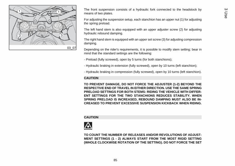
The front suspension consists of a hydraulic fork connected to the headstock bymeans of two plates.
For adjusting the suspension setup, each stanchion has an upper nut (1) for adjustingthe spring preload.
The left hand stem is also equipped with an upper adjuster screw (2) for adjustinghydraulic rebound damping.
The right hand stem is equipped with an upper set screw (3) for adjusting compressiondamping.
Depending on the rider's requirements, it is possible to modify stem setting; bear inmind that the standard settings are the following:
- Preload (fully screwed), open by 5 turns (for both stanchions);
- Hydraulic braking in extension (fully screwed), open by 10 turns (left stanchion);
- Hydraulic braking in compression (fully screwed), open by 10 turns (left stanchion).
CAUTION
TO PREVENT DAMAGE, DO NOT FORCE THE ADJUSTER (1-2) BEYOND THERESPECTIVE END OF TRAVEL IN EITHER DIRECTION. USE THE SAME SPRINGPRELOAD SETTINGS FOR BOTH STEMS: RIDING THE VEHICLE WITH DIFFER-ENT SETTINGS FOR THE TWO STANCHIONS REDUCES STABILITY. WHENSPRING PRELOAD IS INCREASED, REBOUND DAMPING MUST ALSO BE IN-CREASED TO PREVENT EXCESSIVE SUSPENSION KICKBACK WHEN RIDING.
CAUTION
TO COUNT THE NUMBER OF RELEASES AND/OR REVOLUTIONS OF ADJUST-MENT SETTINGS (1 - 2) ALWAYS START FROM THE MOST RIGID SETTING(WHOLE CLOCKWISE ROTATION OF THE SETTING). DO NOT FORCE THE SET
85
3 Use

SCREWS (1 - 2) TO TURN BEYOND THE END OF THE STROKE ON BOTH SIDESSO AS NOT DAMAGE THEM.
(Caponord 1200 Travel Pack)
03_08
This version is configured for use with semi-active shock absorbers
Depending on the rider's requirements, it is possible to only modify the preload on theright stanchion, working on the adjustment nut of the upper plug.
The standard setting of the stanchion is obtained by starting off from a fully closed nut(clockwise) and opening it (anti-clockwise) by 5 turns.
CAUTION
THE ONLY ADJUSTMENT POSSIBLE CAN BE PERFORMED ON THE RIGHTSTANCHION, WHILE THE LEFT ONE CANNOT BE ADJUSTED, SINCE IT ISELECTRONICALLY MANAGED.
03_09
Justering af greb til forbremse (03_09)
Adjust the distance between the lever end and the hand grip by turning the set screw.
To adjust: push the control lever forward and turn the set screw until the arrow pointsat the desired number.
86
3 U
se
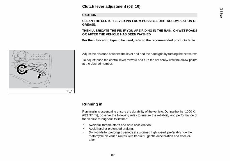
Clutch lever adjustment (03_10)
CAUTION
CLEAN THE CLUTCH LEVER PIN FROM POSSIBLE DIRT ACCUMULATION OFGREASE.
THEN LUBRICATE THE PIN IF YOU ARE RIDING IN THE RAIN, ON WET ROADSOR AFTER THE VEHICLE HAS BEEN WASHED
For the lubricating type to be used, refer to the recommended products table.
03_10
Adjust the distance between the lever end and the hand grip by turning the set screw.
To adjust: push the control lever forward and turn the set screw until the arrow pointsat the desired number.
Running in
Running in is essential to ensure the durability of the vehicle. During the first 1000 Km(621.37 mi), observe the following rules to ensure the reliability and performance ofthe vehicle throughout its lifetime:
• Avoid full throttle starts and hard acceleration;• Avoid hard or prolonged braking;• Do not ride for prolonged periods at sustained high speed; preferably ride the
motorcycle on varied routes with frequent, gentle acceleration and deceler-ation;
87
3 Use
• Ride prudently to gradually gain familiarity with the motorcycle, testing pro-gressively higher throttle apertures only as you gain confidence
CAUTION
THE FULL PERFORMANCE OF THE VEHICLE IS ONLY AVAILABLE AFTER THESERVICE AT THE END OF THE RUNNING IN PERIOD.
Follow these guidelines:
• Do not twist the throttle grip abruptly and completely when the engine isworking at a low revs, either during or after run-in.
• During the first 100 Km (62 miles) use the brakes gently, avoiding sudden orprolonged braking. That is to permit the adequate adjustment of the pad fric-tion material to the brake discs.
AFTER THE SPECIFIED MILEAGE, TAKE YOUR VEHICLE TO AN Official ApriliaDealer FOR THE CHECKS INDICATED IN THE "AFTER-RUN-IN" TABLE IN THESCHEDULED MAINTENANCE SECTION TO AVOID INJURING YOURSELF, OTH-ERS AND /OR DAMAGING THE VEHICLE.
Starting up the engine (03_11, 03_12, 03_13, 03_14, 03_15)
This vehicle is extremely powerful and must be used carefully and driven withcaution and respect for its power and potential.
Do not carry objects in the top fairing (between the handlebar and the instrumentpanel) so that the handlebar can turn freely and the instrument panel is visibleat all times.
88
3 U
se

EXHAUST FUMES CONTAIN CARBON MONOXIDE, AN EXTREMELY HARMFULSUBSTANCE IF INHALED.
NEVER START THE ENGINE IN A CLOSED OR INSUFFICIENTLY VENTILATEDSPACE.
FAILURE TO OBSERVE THIS WARNING COULD LEAD TO UNCONSCIOUSNESSAND EVEN DEATH DUE TO SUFFOCATION.
CAUTION
WITH THE SIDE STAND LOWERED, THE ENGINE MAY ONLY BE STARTED WITHTHE GEARBOX IN NEUTRAL. IF YOU ATTEMPT TO ENGAGE A GEAR IN THISCONDITION THE ENGINE WILL STOP.
WITH THE SIDE STAND RETRACTED, THE ENGINE MAY BE STARTED WITHTHE GEARBOX IN NEUTRAL OR WITH GEAR ENGAGED AND THE CLUTCHLEVER PRESSED.
03_11
• Get onto the bike in riding position.• Make sure that the stand has been fully retracted.• Make sure the light switch (1) is set to the low beam light position.• Set the engine stop switch (2) to RUN.• Turn the key (3) and set the ignition switch to ON.
At this stage:
• On the instrument panel, all warning lights (4) and the backlighting are on for2 seconds.
• The current value is instantly indicated on the instrument panel during regularvehicle riding.
89
3 Use

03_12
IF THE LOW FUEL WARNING LIGHT ON THE INSTRUMENT PANEL TURNS ON,REFUEL THE VEHICLE AT ONCE.
03_13
03_14
• Block at least one wheel by operating one brake lever.• Pull the clutch lever (5) completely and set the gearshift lever (6) to neutral
(green "N" indicator light (7) lit).• There is a starter on the vehicle, controlled by the control unit, that starts
working automatically whenever necessary (cold start).
TO AVOID EXCESSIVE BATTERY CONSUMPTION, DO NOT HOLD DOWN THESTARTER BUTTON (2) MORE THAN TEN SECONDS.
IF THE ENGINE FAILS TO START AFTER THIS TIME, WAIT TEN SECONDS ANDPRESS THE STARTER BUTTON (2) AGAIN.
PRESS THE STARTER BUTTON (2) BUT DO NOT ACCELERATE, AND RELEASEIT AS SOON AS THE ENGINE STARTS.
90
3 U
se

03_15
IF THE ENGINE OIL PRESSURE ICON IS DISPLAYED AND THE GENERALWARNING LIGHT IS BLINKING, THE OIL PRESSURE IN THE CIRCUIT IS TOOLOW.
• Engage at least one brake lever and do not accelerate until you set off.
DO NOT SET OFF SUDDENLY WHEN THE ENGINE IS COLD. RIDE AT LOWSPEED FOR SEVERAL KILOMETRES. THIS WILL ALLOW THE ENGINE TOWARM UP AND REDUCE POLLUTING EMISSIONS AND FUEL CONSUMPTION.
WHEN THE EFI ICON APPEARS AND THE GENERAL WARNING LIGHT IS PER-MANENTLY ON WHILE THE ENGINE IS NORMALLY RUNNING, IT MEANS THEECU HAS DETECTED SOME FAULT. CONTACT AN Official Aprilia Dealer ASAP.
WHEN THE EFI ICON APPEARS AND THE GENERAL WARNING LIGHT IS BLINK-ING WHILE THE ENGINE IS NORMALLY RUNNING, IT MEANS THE ECU HASDETECTED SOME SEVERE FAULT. IMMEDIATELY CONTACT AN Official ApriliaDealer.
91
3 Use

Ride by wire
The vehicle is fitted with an innovative throttle control system, called RIDE BY WIRE,which ensures optimum engine performance, at all times, taking into account the rid-er's demand, the general operating conditions plus the external conditions (atmos-pheric pressure, temperature). If compared with traditional injection systems, it alsoallows an electronic control of the throttle, thus replacing the traditional cable. Whenriding at high altitudes, the RIDE BY WIRE system offsets the unavoidable loss ofpower (1% every 100 metres of slope due to the reduced concentration of oxygen inthe air) by opening the throttle bodies. Therefore, the engine performance when torquedemand is requested by means of the throttle is the same as when riding on levelground, thus shifting the characteristic power reduction to the highest speeds. As aresult, throttles are fully open but the throttle grip is not fully twisted; therefore, in casethe throttle grip is further and fully twisted, the vehicle performance will not be furtherenhanced.
03_16
Moving off / riding (03_16, 03_17, 03_18, 03_19)
CAUTION
IF, WHILE RIDING, THE LOW FUEL WARNING LIGHT (1) ON THE INSTRUMENTPANEL TURNS ON, IT MEANS THERE IS STILL SOME FUEL LEFT.
REFUEL AS SOON AS POSSIBLE.
CAUTION
WHEN TRAVELLING WITHOUT PASSENGERS, MAKE SURE THE PASSENGERFOOTRESTS ARE FOLDED UP.
CAUTION
PASSENGERS MUST BE SUITABLY INSTRUCTED ON HOW TO BEHAVE TOPREVENT DANGEROUS SITUATIONS WHEN RIDING.
BEFORE SETTING OFF, MAKE SURE THE STAND HAS BEEN COMPLETELYRETRACTED TO ITS POSITION.
92
3 U
se

03_17
To start:
• Turn on the engine.• Adjust the inclination of the rear-view mirrors to ensure proper visibility.
CAUTION
WITH THE VEHICLE AT A STANDSTILL, PRACTICE USING THE REAR-VIEWMIRRORS. THE MIRRORS ARE CONVEX, SO OBJECTS MAY SEEM FARTHERAWAY THAN THEY REALLY ARE. THESE MIRRORS OFFER A WIDE-ANGLEVIEW AND ONLY EXPERIENCE HELPS YOU JUDGE THE DISTANCE SEPARAT-ING YOU AND THE VEHICLE BEHIND.
03_18
• With throttle grip (2) closed (Pos. A) and engine at idle, operate the clutchlever (3).
• Push the gearbox lever (4) downward to select the first gear.• Release the clutch lever (activated during start-up).
CAUTION
WHEN TURNING OFF THE VEHICLE, DO NOT RELEASE THE CLUTCH TOOQUICKLY OR SUDDENLY, AS THIS COULD CAUSE THE ENGINE TO STOP ORTHE VEHICLE TO REAR UP ON THE BACK WHEEL. DO NOT ACCELERATESUDDENLY WHEN RELEASING THE CLUTCH FOR THE SAME REASON.
93
3 Use

03_19
• Slowly release the clutch lever (3) and at the same time accelerate by slightlytwisting the throttle grip (2) (Pos. B).
The vehicle starts moving forward.
• For the first kilometres travelled, limit the speed in order to warm up the en-gine.
• Accelerate gradually by twisting the throttle grip (2) (Pos. B) without exceed-ing the recommended rpm.
To engage the second gear:
RIDE IN THE CORRECT GEAR AND SPEED FOR THE CONDITIONS.DO NOT CHANGE GEAR AT A TOO LOW RPM LEVEL.
• Release the throttle grip (2) (Pos. A), operate the clutch lever (3), lift thegearshift lever (4), release the clutch lever (3) and accelerate.
• Repeat the last two operations and engage a higher gear.
IF THE ENGINE OIL PRESSURE ICON IS DISPLAYED AND THE GENERALWARNING LIGHT IS ON DURING REGULAR ENGINE OPERATION, THIS MEANSTHAT THE ENGINE OIL PRESSURE IN THE CIRCUIT IS TOO LOW.
IF THIS OCCURS, STOP THE ENGINE AND CONTACT AN APRILIA Official Deal-er.
94
3 U
se

SHIFTING FROM A HIGHER TO A LOWER GEAR, CALLED "DOWNSHIFT", ISCARRIED OUT:
• When riding downhill and when braking, in order to increase the brakingpower by using engine compression.
• When going uphill, when the engaged gear does not suit the speed (highgear, moderate speed) and the number of engine revs falls.
CAUTION
DOWNSHIFT ONE GEAR AT A TIME; WHEN SHIFTING TO A LOWER GEAR,DOWNSHIFTING MORE THAN ONE GEAR AT A TIME COULD OVERREV THEENGINE; THAT IS, THE MAXIMUM RPM VALUE PERMITTED FOR THE ENGINECOULD BE EXCEEDED.
03_20
Moving off / riding (03_19, 03_20, 03_21, 03_22, 03_23, 03_24,03_25)
CAUTION
IF, WHILE RIDING, THE LOW FUEL WARNING LIGHT (1) ON THE INSTRUMENTPANEL TURNS ON, IT MEANS THERE IS STILL SOME FUEL LEFT.
REFUEL AS SOON AS POSSIBLE.
CAUTION
WHEN TRAVELLING WITHOUT PASSENGERS, MAKE SURE THE PASSENGERFOOTRESTS ARE FOLDED UP.
CAUTION
PASSENGERS MUST BE SUITABLY INSTRUCTED ON HOW TO BEHAVE TOPREVENT DANGEROUS SITUATIONS WHEN RIDING.
BEFORE SETTING OFF, MAKE SURE THE STAND HAS BEEN COMPLETELYRETRACTED TO ITS POSITION.
95
3 Use

03_21
To start:
• Turn on the engine.• Adjust the inclination of the rear-view mirrors to ensure proper visibility.
CAUTION
WITH THE VEHICLE AT A STANDSTILL, PRACTICE USING THE REAR-VIEWMIRRORS. THE MIRRORS ARE CONVEX, SO OBJECTS MAY SEEM FARTHERAWAY THAN THEY REALLY ARE. THESE MIRRORS OFFER A WIDE-ANGLEVIEW AND ONLY EXPERIENCE HELPS YOU JUDGE THE DISTANCE SEPARAT-ING YOU AND THE VEHICLE BEHIND.
03_22
• With throttle grip (2) closed (Pos. A) and engine at idle, operate the clutchlever (3).
• Push the gearbox lever (4) downward to select the first gear.• Release the clutch lever (activated during start-up).
CAUTION
WHEN TURNING OFF THE VEHICLE, DO NOT RELEASE THE CLUTCH TOOQUICKLY OR SUDDENLY, AS THIS COULD CAUSE THE ENGINE TO STOP ORTHE VEHICLE TO REAR UP ON THE BACK WHEEL. DO NOT ACCELERATESUDDENLY WHEN RELEASING THE CLUTCH FOR THE SAME REASON.
96
3 U
se
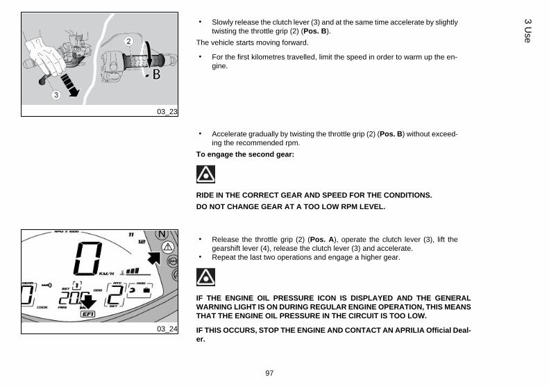
03_23
• Slowly release the clutch lever (3) and at the same time accelerate by slightlytwisting the throttle grip (2) (Pos. B).
The vehicle starts moving forward.
• For the first kilometres travelled, limit the speed in order to warm up the en-gine.
• Accelerate gradually by twisting the throttle grip (2) (Pos. B) without exceed-ing the recommended rpm.
To engage the second gear:
RIDE IN THE CORRECT GEAR AND SPEED FOR THE CONDITIONS.DO NOT CHANGE GEAR AT A TOO LOW RPM LEVEL.
03_24
• Release the throttle grip (2) (Pos. A), operate the clutch lever (3), lift thegearshift lever (4), release the clutch lever (3) and accelerate.
• Repeat the last two operations and engage a higher gear.
IF THE ENGINE OIL PRESSURE ICON IS DISPLAYED AND THE GENERALWARNING LIGHT IS ON DURING REGULAR ENGINE OPERATION, THIS MEANSTHAT THE ENGINE OIL PRESSURE IN THE CIRCUIT IS TOO LOW.
IF THIS OCCURS, STOP THE ENGINE AND CONTACT AN APRILIA Official Deal-er.
97
3 Use

03_25
SHIFTING FROM A HIGHER TO A LOWER GEAR, CALLED "DOWNSHIFT", ISCARRIED OUT:
• When riding downhill and when braking, in order to increase the brakingpower by using engine compression.
• When going uphill, when the engaged gear does not suit the speed (highgear, moderate speed) and the number of engine revs falls.
CAUTION
DOWNSHIFT ONE GEAR AT A TIME; WHEN SHIFTING TO A LOWER GEAR,DOWNSHIFTING MORE THAN ONE GEAR AT A TIME COULD OVERREV THEENGINE; THAT IS, THE MAXIMUM RPM VALUE PERMITTED FOR THE ENGINECOULD BE EXCEEDED.
• Release the throttle grip (2) (Pos. A)• If necessary, pull the brake levers gently and reduce speed.• Operate the clutch lever (3) and lower the gearshift lever (4) to engage a
lower gear.• Release the brake levers when it is operated.• Release the clutch lever (3) and accelerate moderately.
IF AN ENGINE OVER-TEMPERATURE ALARM APPEARS ON THE MULTI-FUNC-TION DIGITAL DISPLAY, STOP THE ENGINE AND CHECK THE LEVEL OF COOL-ING LIQUID. IF THE LEVEL IS INSUFFICIENT, TOP IT UP AFTER HAVING
98
3 U
se

COOLED DOWN THE ENGINE. START THE ENGINE RUNNING, CHECKINGTHAT THE WARNING LIGHT TURNS OFF. IF THE LEVEL IS THE RIGHT ONEAND/OR IF THE WARNING LIGHT CONTINUES TO STAY ON AFTER TOP-UP,CONTACT AN OFFICIAL Aprilia DEALER, USING A TOW TRUCK.X
IF THE TEMPERATURE INDICATOR CONTINUES BLINKING AFTER CHECKINGTHE COOLANT LEVEL, CONTACT AN Official Aprilia Dealer.
LEAVING THE KEY IN "KEY-OK" POSITION, IN ORDER TO AVOID THAT THEFANS STOP, CAUSING THE TEMPERATURE TO RISE FURTHER.
IF THE GENERAL WARNING LIGHT ACTIVATES ON THE INSTRUMENT PANELDURING REGULAR ENGINE OPERATION, THIS MEANS THAT SOME FAILURESHAVE BEEN DETECTED.
IN MANY CASES THE ENGINE WILL CONTINUE TO OPERATE WITH LIMITEDPERFORMANCE; IMMEDIATELY CONTACT AN Official Aprilia Dealer.
IN ORDER TO AVOID CLUTCH OVERHEATING, SHUT THE ENGINE OFF ASSOON AS POSSIBLE ONCE THE VEHICLE HAS STOPPED AND AT THE SAMETIME THE GEAR IS ENGAGED AND THE CLUTCH LEVER OPERATED.
OPERATING ONLY EITHER THE FRONT OR THE REAR BRAKE SIGNIFICANTLYREDUCES BRAKING POWER AND A WHEEL MAY GET BLOCKED RESULTINGIN LACK OF GRIP.
WHEN STOPPING WHILE TRAVELLING UPHILL, CLOSE THE THROTTLE COM-PLETELY AND ONLY USE THE BRAKES TO HOLD THE VEHICLE IN POSITION.
USING THE ENGINE TO HOLD THE VEHICLE ON A HILL MAY CAUSE THECLUTCH TO OVERHEAT.
BRAKING CONTINUOUSLY WHILE GOING DOWNHILL MAY RESULT IN FRIC-TION GASKET OVERHEATING AND CONSEQUENTLY IN POOR BRAKING.
TAKE ADVANTAGE OF THE ENGINE COMPRESSION AND SHIFT UP GEARSUSING THE BRAKES ALTERNATIVELY.
99
3 Use

NEVER RIDE WITH THE ENGINE OFF WHEN GOING DOWNHILL.
WHEN RIDING ON WET SURFACES OR WITH POOR GRIP (SNOW, ICE, MUD,ETC.) RIDE AT A MODERATE SPEED AVOIDING SUDDEN BRAKING OR MA-NOEUVRES THAT MAY LEAD TO LACK OF GRIP AND CONSEQUENTLY TOFALLS.
03_26
Stopping the engine (03_26)
• Release the throttle grip (1) (Pos. A), brake gradually and at the same time"downshift" gears to slow down.
Once the speed is reduced, before stopping the vehicle:
• Operate the clutch lever (2) so that engine does not shut off.When the vehicle is at a standstill:
• Set the gearshift lever in neutral (green "N" indicator light lit).• Release the clutch lever.• While at a temporary halt, keep at least one of the vehicle brakes held.
CAUTION
WHENEVER POSSIBLE, AVOID ROUGH BRAKING, SUDDEN DECELERATIONAND BRAKING IN EXCESS.
Parking
It is very important to select an adequate parking spot, in compliance with road signalsand the guidelines described below.
100
3 U
se

CAUTION
TO MOVE THE MOTORCYCLE, WITH ONE HAND GRAB THE HANDLEBAR ANDWITH THE OTHER ONE THE PASSENGER HANDLE.
CAUTION
PARK ON SAFE AND LEVEL GROUND TO PREVENT THE VEHICLE FROM FALL-ING.
DO NOT LEAN THE VEHICLE AGAINST A WALL OR LAY IT ON THE GROUND.
ENSURE THAT THE VEHICLE AND, IN PARTICULAR, PARTS OF THE VEHICLEWHICH MAY BECOME HOT (ENGINE, OIL RADIATOR AND LINES, EXHAUSTSYSTEM, BRAKE DISCS) ARE NOT A HAZARD TO PERSONS OR CHILDREN.DO NOT LEAVE YOUR VEHICLE UNATTENDED WITH THE ENGINE ON OR THEKEY IN THE IGNITION SWITCH.
CAUTION
IF THE VEHICLE FALLS OR IS ON A STEEP INCLINE FUEL CAN LEAK.
FUEL USED TO DRIVE INTERNAL COMBUSTION ENGINES IS HIGHLY FLAM-MABLE AND CAN BECOME EXPLOSIVE UNDER CERTAIN CONDITIONS.
DO NOT REST THE RIDER OR PASSENGER WEIGHT ON THE SIDE STAND.
Catalytic silencer
The vehicle has a silencer with a "platinum - palladium - rhodium three-way" metalcatalytic converter.
This device oxidises the CO (carbon monoxide) producing carbon dioxide, and theUHC (unburned hydrocarbons) producing water vapour and reduces NOx (nitrogenoxide) producing oxygen and nitrogen present in the exhaust fumes.
101
3 Use

DO NOT PARK THE VEHICLE NEAR DRY BRUSHWOOD OR IN PLACES EASILYACCESSIBLE BY CHILDREN BECAUSE THE CATALYTIC CONVERTER REA-CHES HIGH TEMPERATURES DURING VEHICLE OPERATION; FOR THIS REA-SON, PAY UTMOST ATTENTION AND DO NOT TOUCH IT UNTIL IT HASCOMPLETELY COOLED DOWN.
NEVER USE LEADED PETROL AS THIS WILL CONTAMINATE THE CATALYTICCONVERTER, RENDERING IT INOPERATIVE.
Vehicle owners are warned that the law may prohibit the following:• the removal of any device or element belonging to a new vehicle or any other
action by anyone leading to render it non-operating, if not for maintenance,repair or replacement reasons, in order to control noise emission before thesale or delivery of the vehicle to the ultimate buyer or while it is used;
• using the vehicle after that device or element has been removed or renderednon-operating.
Check the muffler/exhaust silencer and the silencer pipes, make sure there are nosigns of rust or holes and that the exhaust system works properly.
If you not an increase in exhaust noise, take your vehicle to an Official Aprilia Dealerat once.
NOTE
DO NOT TAMPER WITH THE EXHAUST SYSTEM.
102
3 U
se

Stand (03_27, 03_28, 03_29)
THE SIDE AND CENTRE STANDS SHOULD TURN SMOOTHLY, GREASE THEJOINT IF NECESSARY.
SIDE STAND
If the stand has been folded up for any manoeuvre (for example, when the vehicle isin motion), place the vehicle on the stand again as follows:
• Grasp the left grip and put the right hand on the upper rear part of the vehicle.• Push the side stand with your right foot to fully extend the stand.• Lean the vehicle until the stand touches the ground.• Turn the handlebar fully leftwards.
CAUTION
MAKE SURE THE VEHICLE IS STABLE.
03_27
CAUTION
CAREFULLY CLEAN THE STAND JOINT BY REMOVING THE DIRT.
THEN LUBRICATE THE JOINT EVERY 5000 km (31036 mi)
For the lubricating type to be used, refer to the recommended products table.
103
3 Use

03_28
A safety switch is installed on the side stand to inhibit ignition or to stop the enginewhen a gear is engaged and the side stand is lowered.
03_29
CENTRE STAND
(if applicable)
If the stand has been folded up for any manoeuvre (for example, when the vehicle isin motion), place the vehicle on the stand again as follows:
• Grasp the left grip and grab the passenger handle, with the right hand on theupper rear part of the vehicle.
• Push the centre stand downward with your right foot and simultaneously liftthe motorcycle with your right hand and pull it back.
CAUTION
MAKE SURE THE VEHICLE IS STABLE.
Suggestion to prevent theft
CAUTION
WHEN USING A DISC LOCKING DEVICE, PAY UTMOST ATTENTION TO RE-MOVE IT BEFORE RIDING. FAILURE TO OBSERVE THIS WARNING MAY CAUSESERIOUS DAMAGE TO THE BRAKING SYSTEM AND ACCIDENTS WITH CON-SEQUENT PHYSICAL INJURIES OR EVEN DEATH.
104
3 U
se

NEVER leave the ignition key in the lock and always use the steering lock. Park thevehicle in a safe place such as a garage or a place with guards. Whenever possible,use an additional anti-theft device. Make sure all vehicle documents are in order andthe road tax paid. Write down your personal details and telephone number on thispage to help identifying the owner in case of vehicle retrieval after a theft.
LAST NAME: ..................................
NAME: .........................................
ADDRESS: .................................
TELEPHONE NO.: ..........................
WARNING
IN MANY CASES, STOLEN VEHICLES CAN BE IDENTIFIED BY DATA IN THEUSE / MAINTENANCE BOOKLET
03_30
105
3 Use

03_31
03_32
03_33
Basic safety rules (03_31)
Follow the instructions given below attentively to avoid injuring persons, damagingproperty or the vehicle in the event of the rider or the passenger falling off the vehicleand/or the vehicle falling or overturning.
When getting on and off the vehicle, make sure nothing is restricting your movements;do not hold any objects in your hands (helmet, gloves or goggles not put on).
Always get on and off the vehicle on the left side and with the side stand lowered.
106
3 U
se

03_34
The stand has been designed to support the weight of the vehicle and a minimumload, without the added weight of rider and passenger.
The purpose of the side stand is to prevent the vehicle from falling or overturning whilerider and passenger get on the vehicle and get ready to ride; the stand should not beused to support the weight of rider and passenger.
While getting on and off, the vehicle may become unstable due to its weight and itmay fall or overturn.
CAUTION
THE RIDER MUST GET ON THE VEHICLE FIRST AND GET OFF LAST TO BEABLE TO CONTROL AND BALANCE THE VEHICLE WHILE THE PASSENGER ISGETTING ON OR OFF THE VEHICLE.
When getting on and off the vehicle, the passenger must move carefully so as not tocause a loss of stability for vehicle and rider.
CAUTION
THE RIDER MUST INSTRUCT THE PASSENGER ON HOW TO GET ON AND OFFTHE VEHICLE SAFELY.
THE VEHICLE IS EQUIPPED WITH PASSENGER FOOTRESTS TO FACILITATEGETTING ON OR OFF THE VEHICLE. THE PASSENGER MUST ALWAYS USETHE LEFT FOOTREST TO GET ON AND OFF THE VEHICLE.
NEVER ATTEMPT TO GET OFF THE VEHICLE BY JUMPING OR STRETCHINGYOUR LEG TO REACH THE GROUND. THESE ARE INCORRECT PROCEDURESTHAT COMPROMISE VEHICLE STABILITY AND BALANCE.
CAUTION
ANY BAGS OR OBJECTS STRAPPED TO THE REAR OF THE VEHICLE CANREPRESENT AN OBSTACLE WHILE GETTING ON AND OFF.
107
3 Use

SWING YOUR RIGHT LEG OVER THE SEAT IN A CONTROLLED MOVEMENT SOAS NOT TO HIT THE REAR PART OF THE VEHICLE (TAIL FAIRING OR LUG-GAGE) AND COMPROMISE STABILITY.
GETTING ON THE VEHICLE
• Grip the handlebar correctly and get on the vehicle without resting yourweight on the side stand
CAUTION
IF YOU CAN NOT REACH THE GROUND WITH BOTH FEET WHEN SEATED,PLACE YOUR RIGHT FOOT ON THE GROUND (IF YOU LOSE BALANCE, THESIDE STAND WILL PREVENT A FALL ON THE LEFT SIDE) AND BE READY TOPUT YOUR LEFT FOOT ON THE GROUND.
• Place both feet on the ground, straighten and balance the vehicle keeping itupright in riding position.
CAUTION
THE RIDER MUST NOT EXTRACT OR ATTEMPT TO EXTRACT THE PASSENGERFOOTRESTS WHILE SEATED, BECAUSE THIS MIGHT COMPROMISE VEHICLESTABILITY AND BALANCE.
• Have the passenger fold out the two passenger footrests.• Give instructions as necessary to help the passenger mount the vehicle.• Lift and retract the side stand completely with the left foot.
GETTING OFF THE VEHICLE
• Select an appropriate parking spot.• Stop the vehicle.
108
3 U
se

MAKE SURE THAT THE GROUND ON WHICH THE MOTORCYCLE IS PARKEDIS STABLE, EVEN AND FREE OF OBSTACLES.
• With the left shoe heel, lower and extend the side stand completely.
CAUTION
IF YOU CAN NOT REACH THE GROUND WITH BOTH FEET WHEN SEATED,PLACE YOUR RIGHT FOOT ON THE GROUND (IF YOU LOSE BALANCE, THESIDE STAND WILL PREVENT A FALL ON THE LEFT SIDE) AND BE READY TOPUT YOUR LEFT FOOT ON THE GROUND.
• Place both feet on the ground and keep the vehicle balanced in the uprightposition.
• Give instructions as necessary to help the passenger dismount the vehicle.
RISK OF FALLING AND OVERTURNING.MAKE SURE THE PASSENGER HAS GOT OFF THE VEHICLE.DO NOT REST YOUR WEIGHT ON THE SIDE STAND.
• Tilt the motorcycle until the stand touch the ground.• Grasp the handlebar firmly and get off the vehicle.• Turn the handlebar fully leftwards.• Return the passenger footrests to position.
109
3 Use

CAUTION
MAKE SURE THE VEHICLE IS STABLE.
110
3 U
se

CAPONORD
Chap. 04Maintenance
111

04_01
Engine oil level check (04_01, 04_02, 04_03)
Check the engine oil level frequently.
NOTE
CARRY OUT MAINTENANCE OPERATIONS AT HALF THE INTERVALS SPECI-FIED IF THE VEHICLE IS USED IN PARTICULAR RAINY OR DUSTY CONDI-TIONS, OFF ROAD OR FOR TRACK USE.
ENGINE OIL LEVEL MUST BE CHECKED WHEN THE ENGINE IS WARM.
IF YOU CHECK LEVEL WHEN THE ENGINE IS COLD, OIL LEVEL COULD TEM-PORARILY DROP BELOW THE "MIN" MARK.
THIS SHOULD NOT BE CONSIDERED A PROBLEM PROVIDED THAT THEALARM WARNING LIGHT AND THE ENGINE OIL PRESSURE ICON DO NOTTURN ON SIMULTANEOUSLY ON THE DISPLAY.
CAUTION
DO NOT LET THE ENGINE IDLE WITH THE VEHICLE AT STANDSTILL TO WARMUP THE ENGINE AND OBTAIN THE OPERATING TEMPERATURE OF ENGINEOIL.
PREFERABLY CHECK THE OIL AFTER A JOURNEY OF AFTER TRAVELLINGAPPROXIMATELY 15 Km (10 miles) IN EXTRAURBAN CONDITIONS (ENOUGHTO WARM UP THE ENGINE OIL TO OPERATING TEMPERATURE).
112
4 M
aint
enan
ce

04_02
04_03
• Switch off the engine and wait at least five minutes to allow the lubricant todrain back into the sump.
• Keep the vehicle upright on a level surface and with both wheels on theground.
• Check the oil level from the sight glass on the clutch case.MAX = maximum level.
MIN = minimum level
The difference between the "MAX" and "MIN" marks is approx. 460 cm³ (28.07 cu.in).
• The oil level is correct when it is close to the "MAX" mark.
CAUTION
THE VEHICLE MUST BE UNLOADED.
04_04
Engine oil top-up (04_04)
CAUTION
DO NOT GO BEYOND THE "MAX" AND BELOW THE "MIN" LEVEL MARK TOAVOID SEVERE ENGINE DAMAGE.
113
4 Maintenance

Fill with engine oil as required:
• Unscrew and remove the cap (1).When using a funnel or any other element, make sure it is perfectly clean.
DO NOT ADD ADDITIVES OR OTHER SUBSTANCES TO THE OIL.
CAUTION
USE OIL WITH THE SPECIFICATIONS INDICATED IN THE RECOMMENDEDPRODUCTS TABLE GIVEN AT THE END OF THE MANUAL.
• Top-up the oil in the reservoir until you reach the correct level.
Engine oil change
CAUTION
TO CHANGE THE ENGINE OIL, PLEASE CONTACT AN Official aprilia Dealer. IFYOU ARE ADEQUATELY TRAINED AND EXPERIENCED, REFER TO THE IN-STRUCTIONS IN THE WORKSHOP BOOKLET AVAILABLE ALSO AT ANY DEAL-ER.
Engine oil filter replacement
CAUTION
TO REMOVE AND CLEAN THE ENGINE OIL FILTER, PLEASE CONTACT AN Of-ficial aprilia Dealer. IF YOU ARE ADEQUATELY TRAINED AND EXPERIENCED,
114
4 M
aint
enan
ce

REFER TO THE INSTRUCTIONS IN THE WORKSHOP BOOKLET AVAILABLEALSO AT ANY DEALER.
Tyres
This vehicle is fitted with tyres without inner tubes (Tubeless).
CHECK TYRE INFLATION PRESSURE REGULARLY, AT LEAST ONCE AMONTH, AT AMBIENT TEMPERATURE.
MEASUREMENTS MAY BE INCORRECT IF TYRES ARE WARM.
CHECK PRESSURE MAINLY BEFORE AND AFTER LONG TRIPS.
IF THE TYRE PRESSURE IS TOO HIGH, UNEVENNESS IN THE ROAD SURFACEWILL NOT BE DAMPED AND WILL BE TRANSMITTED TO THE HANDLEBAR,RESULTING IN AN UNPLEASANTLY HARSH RIDE AND POOR ROAD HOLDING ,ESPECIALLY WHEN CORNERING.
AN UNDERINFLATED TYRE, ON THE OTHER HAND, WILL EXTEND THE CON-TACT PATCH TO INCLUDE A LARGER PORTION OF THE TYRE SIDEWALLS.WHEN THIS IS THE CASE, THE TYRE MIGHT SLIP ON OR BECOME DETACHEDFROM THE WHEEL RIM, LEADING TO LOSS OF CONTROL OVER THE VEHICLE.
TYRES MAY EVEN DETACH FROM THE WHEEL RIMS UNDER VERY HARDBRAKING.
THE VEHICLE MAY EVEN SKID IN A BEND.
INSPECT TREAD SURFACE AND CHECK IT FOR WEAR. BADLY WORN TYRESMAY COMPROMISE TRACTION AND HANDLING.
REPLACE TYRES WHEN WORN OR IF THERE IS A PUNCTURE IN THE TREADAREA BIGGER THAN 5 mm (0.197 in).
115
4 Maintenance

BALANCE WHEELS AFTER A TYRE IS MENDED. USE ONLY TYRE SIZES INDI-CATED BY THE MANUFACTURER.
CHECK THAT THE INFLATION VALVES HAVE THEIR CAPS FITTED TO AVOIDUNEXPECTED FLAT TYRES. REPLACEMENT, REPAIR, MAINTENANCE ANDBALANCING OPERATIONS ARE HIGHLY IMPORTANT AND SO THEY SHOULDBE CARRIED OUT USING THE SPECIFIC TOOLS AND WITH THE ADEQUATEKNOWLEDGE.
IT IS THEREFORE ESSENTIAL TO TAKE YOUR VEHICLE TO AN Official ApriliaDealer OR SPECIALISED TYRE WORKSHOP TO CARRY OUT THE OPERATIONSABOVE. NEW TYRES MAY BE COATED WITH A SLIPPERY COATING: RIDEWITH CAUTION DURING THE FIRST KILOMETRES. DO NOT APPLY UNSUITA-BLE LIQUIDS ON TYRES. WHEN TYRES ARE OLD, THE MATERIAL MAY HARD-EN AND NOT PROVIDE ADEQUATE ROAD HOLDING, EVEN IF TYRES ARESTILL WITHIN THE WEAR LIMIT.
SHOULD THIS OCCUR, REPLACE THE TYRES.
Minimum tread depth:
front and rear 2 mm (0.079 in) (USA 3 mm - 0.118 in) or more if so required by appli-cable legislation in the country where the vehicle is used.
Spark plug dismantlement
CAUTION
TO REMOVE, CHECK, CLEAN AND REPLACE SPARK PLUGS, PLEASE CON-TACT AN Official Aprilia Dealer. IF YOU HAVE SUFFICIENT EXPERIENCE, FOL-LOW THE INSTRUCTIONS IN THIS WORKSHOP BOOKLET, WHICH IS AVAILA-BLE AT ANY DEALER.
116
4 M
aint
enan
ce

Removing the air filter
CAUTION
TO REMOVE, CHECK AND REPLACE THE AIR FILTER, PLEASE CONTACT ANOfficial Aprilia Dealer. IF YOU ARE ADEQUATELY TRAINED AND EXPERI-ENCED, REFER TO THE INSTRUCTIONS IN THIS WORKSHOP BOOKLET AVAIL-ABLE ALSO AT ANY DEALER.
Cooling fluid level (04_05, 04_06)
DO NOT USE YOUR MOTORCYCLE IF THE COOLANT LEVEL IS BELOW THEMINIMUM LEVEL MARKED «MIN».
CAUTION
COOLANT IS TOXIC IF INGESTED; CONTACT WITH YOUR EYES OR SKIN MAYCAUSE IRRITATION. IF THE FLUID GETS IN CONTACT WITH THE EYES ORSKIN, RINSE REPEATEDLY WITH PLENTY OF WATER AND SEEK MEDICALADVICE. IF SWALLOWED, INDUCE VOMITING, RINSE MOUTH AND THROATWITH PLENTY OF WATER AND SEEK MEDICAL ADVICE IMMEDIATELY.
CAUTION
TAKE CARE NOT TO POUR COOLANT ONTO HOT ENGINE OR EXHAUST SYS-TEM COMPONENTS; THE FLUID MAY CATCH FIRE AND BURN WITH INVISIBLEFLAMES. WHEN CARRYING OUT MAINTENANCE OPERATIONS, IT IS ADVISA-
117
4 Maintenance

BLE TO WEAR LATEX GLOVES. CONTACT AN Official APRILIA Dealer FORREPLACEMENT.
DO NOT DISPOSE OF THE FLUID INTO THE ENVIRONMENT.
KEEP OUT OF THE REACH OF CHILDREN
DO NOT REMOVE THE COVER OF THE EXPANSION TANK (1) WHEN THE EN-GINE IS HOT AS THE COOLANT IS UNDER PRESSURE AND AT A HIGH TEM-PERATURE. CONTACT WITH SKIN OR CLOTHES MAY CAUSE SERIOUSBURNS AND/OR INJURIES.
NOTE
TAKE YOUR VEHICLE TO AN Official APRILIA Dealer TO HAVE THE COOLANTCHANGED.
WARNING
WAIT FOR THE ENGINE TO COOL DOWN BEFORE CHECKING OR TOPPING-UP THE COOLANT LEVEL.
04_05
CHECK AND TOPPING-UP
• Shut off the engine and wait until it cools off.• Keep the vehicle upright and with the two wheels on the ground.• Turn the handlebar to the left, keeping the vehicle upright.• Make sure that the coolant level in the expansion tank is between the
"MAX" ("MAX"= maximum level) and "MIN" ("MIN"= minimum level) refer-ence marks
118
4 M
aint
enan
ce

04_06
Otherwise:
• Remove the filler cap (1).• Top-up with recommended coolant until the coolant level is near the "MAX"
reference mark. Do not exceed this level or the coolant will spill out when theengine is turning.
• Refit and lock the filler cap (1).
CAUTION
IN THE EVENT OF COOLANT CONSUMPTION OR IF THE RESERVOIR IS EMP-TIES, CHECK FOR LEAKS IN THE CIRCUIT.
04_07
Checking the brake oil level (04_07, 04_08)
For the front brake:
• rest the vehicle on its stand and turn the handlebar so that the fluid in thereservoir is parallel to the reservoir edge.
• Check that the fluid in the reservoir is above the "MIN" reference mark.For the rear brake:
• keep the vehicle upright and check that the fluid in the reservoir is parallel tothe reservoir edge.
• Make sure that the fluid level in the reservoir is above the "MIN" referencemark:
Top-up if the fluid does not reach at least the "MIN" reference mark.
• Check brake pads and disc for wear• If the pads and/or the disc do not need replacing, top up the fluid.
119
4 Maintenance

04_08
Braking system fluid top up
CAUTION
TO HAVE THE BRAKING SYSTEM FLUID TOPPED-UP, PLEASE CONTACT ANOfficial Aprilia Dealer. IF YOU ARE SUITABLY AND EXPERIENCED, FOLLOWTHE INSTRUCTIONS IN THE WORKSHOP BOOKLET, WHICH IS AVAILABLEFROM ANY DEALER.
04_09
Checking clutch fluid (04_09)
• Rest the vehicle on its stand.• Turn the handlebar so that the fluid in the reservoir is parallel to the reservoir
edge.• Make sure that the fluid level in the reservoir is above the "MIN" reference
mark:Top-up if the fluid does not reach at least the "MIN" reference mark.
120
4 M
aint
enan
ce

Topping up clutch fluid
CAUTION
FOR CLUTCH FLUID TOP-UP, PLEASE CONTACT AND Official Aprilia Dealer. IFYOU ARE ADEQUATELY TRAINED AND EXPERIENCED, REFER TO THE IN-STRUCTIONS IN THIS WORKSHOP BOOKLET AVAILABLE ALSO AT ANYDEALER.
04_10
Battery removal (04_10, 04_11, 04_12)
• Make sure that the ignition switch is set to "OFF";• Remove the saddle.• Remove the tool kit;• Remove the fixing screw (1) of the rider saddle;
04_11
• Undo the screws (2) and remove the cover (3);
121
4 Maintenance

04_12
• Slightly lift the battery• Unscrew and remove the screw (3) from the negative terminal clamp (-);• Move the negative lead (4) aside;• Unscrew and remove the screw (5) of the positive terminal (+);• Move the positive lead (6) aside;• Remove the battery
CAUTION
WHEN REFITTING THE BATTERY, MAKE SURE IT IS CORRECTLY POSITIONEDAND POLES ARE NOT INVERTED.
CAUTION
UPON REFITTING, CONNECT THE LEAD TO THE POSITIVE TERMINAL (+) FIRSTAND AFTERWARDS THE LEAD TO THE NEGATIVE TERMINAL (-).
CHECK THAT THE BATTERY LEADS AND TERMINALS ARE:
- IN GOOD CONDITION (NOT CORRODED OR COVERED BY DEPOSITS);
- COVERED BY NEUTRAL GREASE OR PETROLEUM JELLY.
Checking the electrolyte level
WARNING
THIS VEHICLE IS FITTED WITH A MAINTENANCE-FREE BATTERY AND DOESNOT NEED ANY INTERVENTION, EXCEPT FOR SPORADIC CHECKS AND RE-CHARGE.
Charging the battery
• Remove the battery.
122
4 M
aint
enan
ce

• Get an adequate battery charger.• Set the battery charger for the recharge type indicated.• Connect the battery to the battery charger.
CAUTION
WHEN RECHARGING OR USING THE BATTERY, BE CAREFUL TO HAVE THEROOM ADEQUATELY AIRED. DO NOT BREATH GASES RELEASED WHEN THEBATTERY IS RECHARGING.
Switch on the battery charger.
CharacteristicRecharge modes
Recharge - Ordinary
Electric Current - 1.0 A
Time - 8-10 hours
Recharge - Fast
Electric Current - 6 A
Time - 1 hour
123
4 Maintenance

Long periods of inactivity
IF THE VEHICLE IS OUT OF USE FOR MORE THAN TWENTY DAYS, DISCON-NECT THE 30 A FUSE TO PREVENT BATTERY DETERIORATION CAUSED BYCURRENT CONSUMPTION BY THE MULTIFUNCTION COMPUTER.
CAUTION
REMOVING THE 30 A FUSES RESETS THESE FUNCTIONS: DIGITAL CLOCK,TRIP INFORMATION AND CHRONOMETER TIMES.
If the vehicle is inactive longer than fifteen days, it is necessary to recharge the batteryto avoid sulphation.
• Remove the battery.In winter or when the vehicle is out of use for prolonged periods, check charge levelfrequently (about once a month) to prevent deterioration.
• Recharge it fully with an ordinary charge.If the battery is still on the vehicle, disconnect the cables from the terminals.
NOTE
THE FIRST TIME THE ENGINE IS STARTED AFTER RECONNECTING THE BAT-TERY LEADS, WAIT 20 SECONDS BETWEEN THE MOMENT THE KEY IS SETTO "KEY ON" AND THE MOMENT THE STARTER BUTTON CAN BE PUSHED.
THE ENGINE WILL NOT START IF START-UP IS ATTEMPTED BEFORE THEPRE-SET 20 SECONDS ELAPSE.
124
4 M
aint
enan
ce

Fuses (04_13, 04_14, 04_15, 04_16)
Check all the fuses in case of failure or irregular functioning of an electrical componentor engine starting failure.
CAUTION
DO NOT REPAIR FAULTY FUSES.
NEVER USE A FUSE THAT IS DIFFERENT THAN WHAT IS SPECIFIED TO PRE-VENT DAMAGES TO THE ELECTRICAL SYSTEM OR SHORT CIRCUITS, ANDTHE RISK OF FIRE.
CAUTION
A FUSE THAT BLOWS FREQUENTLY MAY INDICATE A SHORT CIRCUIT OROVERLOAD. IF THIS OCCURS, CONSULT AN APRILIA Official Dealer.
04_13
To check:
• Set the ignition switch to "OFF" to avoid an accidental short circuit.• Open the cover of the secondary fuse box on the front left.• Take out one fuse at a time and check if the filament is broken.• Before replacing the fuse, find and solve, whenever possible, the problem
that caused it to blow.• If the fuse is damaged, replace it with one of the same current rating.• To check the main fuses, located under the cover in the compartment be-
neath the saddle, carry out the same operations described above for thesecondary fuses.
NOTE
IF THE SPARE FUSE IS USED, REPLACE WITH ONE OF THE SAME TYPE IN THECORRESPONDING FITTING.
125
4 Maintenance

CAUTION
REMOVING THE 30 A FUSES RESETS THESE FUNCTIONS: DIGITAL CLOCK,TRIP INFORMATION AND CHRONOMETER TIMES.
• To access the secondary fuse box, remove the fixing clip of the flap on theleft inner side of the dashboard.
04_14
• Remove the flap.
SECONDARY FUSES (front left side, above the water radiator) (Caponord 1200)
1 A - Recovery logic relay (safety), Stop, Horn, Daylight running light, License platelight (10 A).
2 - Instrument panel power supply, anti-theft power supply (if installed), EVC powersupply, arrangement + bludeash key (7.5 A).
3 - ECU positive live (15 A).
4 - Permanent ECU positive (7.5 A).
5 - Coils, injectors, petrol pump (15 A).
6 - Low beam/high beam light power, relay lights (15 A).
7 - Fans (15 A).
126
4 M
aint
enan
ce

NOTE
THREE FUSES (8) ARE SPARE FUSES
04_15
SECONDARY FUSES (front left side, above the water radiator) (Caponord 1200Travel Pack)
1 A - Recovery logic relay (safety), Stop, Horn, Daylight running light, License platelight (10 A).
2 - Instrument panel power supply, anti-theft power supply (if installed), VCU powersupply, arrangement + bludeash key (7.5 A).
3 - ECU positive live (15 A).
4 - Permanent ECU positive (7.5 A).
5 - Coils, injectors, petrol pump (15 A).
6 - Low beam/high beam light power, relay lights (15 A).
7 - Fans (15 A).
NOTE
THREE FUSES (8) ARE SPARE FUSES
04_16
MAIN FUSES - (under the saddle, remove the battery protection)
A - Battery recharge, primary injection relay, key, arrangement + permanent bluedash(30 A)
127
4 Maintenance

B - Permanent ECU ABS positive (20 A).
C - Electrical socket, heated handgrips (if installed), anti-theft, GPS power supply (7.5A)
NOTE
THREE FUSES (D) ARE SPARE FUSES
Lamps
CAUTION
BEFORE REPLACING A BULB, TURN THE IGNITION SWITCH TO «KEY OFF»AND WAIT A FEW MINUTES FOR THE BULB TO COOL OFF.
WEAR CLEAN GLOVES OR USE A CLEAN DRY CLOTH TO REPLACE THEBULB.
DO NOT LEAVE PRINTS ON THE BULB AS THIS MAY CAUSE IT TO OVERHEATOR EVEN BLOW OUT. IF YOU TOUCH THE BULB WITHOUT WEARING GLOVES,CLEAN OFF PRINTS WITH ALCOHOL TO AVOID DAMAGING THE BULB.
DO NOT FORCE ELECTRICAL CABLES.
BULB LAYOUT
In the headlamp there are:
- two tail light bulbs (side)
- two low beam light bulbs (side);
- a high beam light bulb (central);
128
4 M
aint
enan
ce

In the taillight there are:
- 10 LED
04_17
Low/High beam lamp replacement (04_17, 04_18)
REPLACEMENT OF LOW BEAM BULB
• Rest the vehicle on its stand.• Disconnect the connector (1)
04_18
• Turn the bulb holder (2) anticlockwise and remove it;• Replace the bulb
129
4 Maintenance

04_19
Position light replacement (04_19, 04_20)
Replacement of the Daylight running light bulb
• Rest the vehicle on its stand.• Disconnect the connector (1)
04_20
• Turn the bulb holder (2) anticlockwise and remove it;• Replace the bulb
Front light group
NOTE
IN CASE OF MOTORCYCLE WASH OR IN CASE OF BOUNCING VARIATIONS,THE FRONT PROJECTOR MIGHT MIST UP. THE BEHAVIOUR IS TOTALLY NOR-MAL AND THE CONDENSED WATER WILL QUICKLY DISAPPEAR BY USINGTHE LOW BEAM AND HIGH BEAM FUNCTION
130
4 M
aint
enan
ce

04_21
Headlight adjustment (04_21, 04_22, 04_23, 04_24, 04_25,04_26)
NOTE
IN COMPLIANCE WITH LOCAL LEGISLATION, SPECIFIC PROCEDURES MUSTBE FOLLOWED WHEN ALIGNING THE LIGHTS.
04_22
To quickly and easily check the alignment of the front light, place the vehicle on a levelsurface 10 m (32.8 ft) away from a vertical wall. Turn on the dipped beam light, sit onthe vehicle and check that the light beam projected onto the wall is a little below thelevel of the headlight (about 9/10 of the total height).
To carry out vertical adjustment of the light beam:
• Rest the vehicle on its stand.• Remove the horn fixing screw (1).
04_23
• Remove the horn (2) after having disconnected the connectors
131
4 Maintenance

04_24
• Remove the fixing screws (3) and remove the protection lid (4)
04_25
• Working from underneath the windshield, operate on the relevant screw (5).SCREW it (clockwise) to move the light beam up; UNDO it (anticlockwise) tomove the light beam down.
04_26
In order to carry out horizontal adjustment of the light beam:
• Rest the vehicle on its stand.• Working from the rear side of the windshield, use a crosshead screwdriver
to operate on the specific central screws (6). SCREW it (clockwise) to movethe light beam to the left; UNDO it (anticlockwise) to move the light beam tothe right.
NOTE
CHECK THAT THE LIGHT BEAM HORIZONTAL DIRECTION IS CORRECT.
132
4 M
aint
enan
ce

04_27
Front direction indicators (04_27)
• Rest the vehicle on its stand.• Loosen and remove screw (1).• Remove glass (2).• Press bulb (3) slightly and turn it anticlockwise.• Pull the bulb (3) out of its fitting.• Insert a bulb of the same type adequately.
WARNING
IF THE HEADLIGHT (4) PROTRUDES FROM ITS FITTING, INSERT IT AGAINPROPERLY.
Rear optical unit
CAUTION
TO REMOVE, CHECK AND REPLACE THE BULB, PLEASE CONTACT AN OfficialAprilia Dealer. IF YOU ARE ADEQUATELY TRAINED AND EXPERIENCED, RE-FER TO THE INSTRUCTIONS IN THIS WORKSHOP BOOKLET AVAILABLE ALSOAT ANY DEALER.
133
4 Maintenance

04_28
Rear turn indicators (04_28)
• Rest the vehicle on its stand.• Loosen and remove screw (1).• Remove glass (2).• Press bulb (3) slightly and turn it anticlockwise.• Pull the bulb (3) out of its fitting.• Insert a bulb of the same type adequately.
WARNING
IF THE HEADLIGHT (4) PROTRUDES FROM ITS FITTING, INSERT IT AGAINPROPERLY.
04_29
Number plate light (04_29, 04_30)
• Remove the bulb holder fixing screw (1)
134
4 M
aint
enan
ce

04_30
• Remove the bulb (3) from the bulb holder (2).• Insert a bulb of the same type adequately.
Rear-view mirrors (04_31, 04_32)
• Park the vehicle on its centre stand on safe and level ground.• Move the protection casing (1).
HOLD THE REAR-VIEW MIRROR (4) TO AVOID DROPPING IT BY ACCIDENT.
04_31
• Keep the screw (2) blocked and completely unscrew the nut (3).
HANDLE PLASTIC AND PAINTED COMPONENTS WITH CARE, DO NOTSCRATCH OR SPOIL THEM.
135
4 Maintenance

• Remove the rear-view mirror (4).
CAUTION
REPEAT THE PROCEDURE TO REMOVE THE OTHER MIRROR.
AFTER REFITTING, ADJUST THE REAR-VIEW MIRRORS CORRECTLY ANDTIGHTEN THE NUTS IN ORDER TO ENSURE STABILITY.
04_32
After refitting:
• Adjust the rear-view mirror angle correctly.
Front and rear disc brake (04_33, 04_34)
THOROUGHLY DRY THE BRAKE DISCS WHEN YOU HAVE FINISHED CLEAN-ING TO AVOID THE PADS STICKING TO THE DISCS.
136
4 M
aint
enan
ce

CAUTION
CHECK THE BRAKE PAD WEAR BEFORE EACH TRIP AND EVERY 5000 km(3106 mi).
04_33
04_34
To perform a quick pad wear check:
• Rest the vehicle on its stand.• Carry out a visual inspection of brake disc and pads as follows:
- at the front, for the front brake callipers;
- on the right side of the vehicle, look from above downwards, for the rear brake cal-liper.
CAUTION
EXCESSIVE WEAR OF THE FRICTION MATERIAL MAKES THE PAD METALSUPPORT GET INTO CONTACT WITH THE DISC, WHICH RESULTS IN A MET-ALLIC NOISE AND SPARKS IN THE CALLIPER; THEREFORE, BRAKING EFFI-CIENCY AND DISC SAFETY AND INTEGRITY ARE AT RISK.
137
4 Maintenance

If the friction material thickness (even of one front or rear pad) is reduced to a valueof about 1.5 mm (0.06 in) (or even if one of the wear indicators is not very visible),contact an Official Aprilia Dealer to have all the calliper pads replaced.
04_35
Periods of inactivity (04_35)
Take some measures to avoid the side effects of not using the scooter. Besides, it isnecessary to carry out general repairs and checks before garaging the motorcycle asone can forget to do so afterwards.
Proceed as follows:
• Remove the battery.• Wash and dry the vehicle.• Polish the painted surfaces.• Inflate the tyres.• Set the vehicle in a room with no heating or humidity, with minimum temper-
ature variations and not exposed to sun rays.• Wrap and tie a plastic bag around the exhaust pipe opening to keep moisture
out.
NOTE
PLACE A SUITABLE SUPPORT UNDER THE VEHICLE TO KEEP BOTH WHEELSOFF THE GROUND.
• Put the vehicle on the front stand (optional) and on the back stand (optional).• Cover the vehicle (do not use plastic or waterproof materials).
AFTER STORAGE
138
4 M
aint
enan
ce

NOTE
PULL OUT THE PLASTIC BAG FROM THE PIPE OPENING.
• Uncover and clean the vehicle.• Check the battery for correct charge and install it.• Refill the fuel tank.• Carry out the pre-ride checks.
CAUTION
AS A TEST, RIDE THE MOTORCYCLE FOR A FEW KILOMETRES AT A MODER-ATE SPEED AND AWAY FROM TRAFFIC AREAS.
Cleaning the vehicle (04_36, 04_37, 04_38)
Clean the motorcycle frequently if exposed to adverse conditions, such as:• Air pollution (cities and industrial areas).• Salinity and humidity in the atmosphere (seashore areas, hot and wet weath-
er).• Special environmental/seasonal conditions (use of salt, anti-icing chemical
products on the roads in winter).• Always clean off any smog and pollution residue, tar stains, insects, bird
droppings, etc. from the bodywork.• Avoid parking the vehicle under trees. In some seasons, as from the trees
may fall residues, resins, fruits or leaves that contain chemicals which areharmful to the paintwork.
139
4 Maintenance

CAUTION
BEFORE WASHING THE VEHICLE, COVER THE ENGINE AIR INTAKES AND THEEXHAUST PIPES.
CAUTION
CLEAN THE INSTRUMENT PANEL WITH A SOFT CLOTH MOISTENED WITHWATER.
CAUTION
BEFORE WASHING THE WINDSCREEN, SOFTEN THE DIRT WITH WATER.THEN CLEAN WITH A SOFT CLOTH MOISTENED WITH WATER.
CAUTION
AFTER CLEANING YOUR MOTORCYCLE, BRAKING EFFICIENCY MAY BE TEM-PORARILY AFFECTED DUE TO THE PRESENCE OF WATER ON THE FRICTIONSURFACES OF THE BRAKING CIRCUIT. ALLOW LONGER BRAKING DISTAN-CES TO PREVENT ACCIDENTS. BRAKE REPEATEDLY TO RESTORE NORMALOPERATION. CARRY OUT THE PRE-RIDE CHECKS.
To remove dirt and mud accumulated on painted surfaces, wet the soiled areas thor-oughly with a low-pressure water jet, then remove dirt and mud with a soft car bodysponge soaked abundantly in a solution of car body shampoo in water (2 - 4% sham-poo dissolved in water). Then rinse with plenty of water, and dry with a chamois
140
4 M
aint
enan
ce

leather. To clean the engine outer parts, use degreasing detergent, brushes and oldcloths. Wash anodised or painted aluminium parts with neutral soap and water. Usingaggressive detergents may damage the surface treatment of these components.
TO CLEAN THE HEADLIGHTS USE A SPONGE SOAKED IN WATER AND MILDDETERGENT, RUBBING THE SURFACE GENTLY AND RINSING FREQUENTLYWITH PLENTY OF WATER. REMEMBER TO CLEAN THE VEHICLE CAREFULLYBEFORE APPLYING SILICON WAX POLISH. DO NOT POLISH MATT-PAINTEDSURFACES WITH POLISHING PASTE. THE VEHICLE SHOULD NEVER BEWASHED IN DIRECT SUNLIGHT, ESPECIALLY DURING SUMMER, OR WITH THEBODYWORK STILL HOT AS THE CAR SHAMPOO CAN DAMAGE THE PAINT-WORK IF IT DRIES BEFORE BEING RINSED OFF.
CAUTION
DO NOT USE WATER (OR LIQUIDS) AT TEMPERATURES OVER 40°C (104°F)WHEN CLEANING THE VEHICLE PLASTIC PARTS. DO NOT AIM HIGH PRES-SURE AIR/WATER JETS OR STEAM JETS DIRECTLY ON THESE COMPO-NENTS. DO NOT USE ALCOHOL OR SOLVENTS TO CLEAN ANY RUBBER ORPLASTIC SADDLE COMPONENTS: USE WATER AND MILD SOAP.
CAUTION
DO NOT USE SOLVENTS OR PETROL BY-PRODUCTS (ACETONE, TRICHLORO-ETHYLENE, TURPENTINE, PETROL, THINNERS) TO CLEAN THE SADDLE. USEINSTEAD DETERGENTS WITH SURFACE ACTIVE AGENTS NOT EXCEEDING5% (NEUTRAL SOAP, DEGREASING DETERGENTS OR ALCOHOL).
DRY THE SADDLE WELL AFTER CLEANING.
141
4 Maintenance

CAUTION
DO NOT APPLY PROTECTIVE WAX ON THE SADDLE AS IT MAY BECOME SLIP-PERY.
04_36
04_37
WHEN USING A HIGH PRESSURE CLEANING SYSTEM (AFTER ENSURINGTHAT THE DETERGENT USED IS COMPATIBLE WITH THE MOTORCYCLE FIN-ISH), MAINTAIN A DISTANCE OF AT LEAST HALF A METRE BETWEEN THENOZZLE AND THE SURFACE BEING CLEANED.
142
4 M
aint
enan
ce

04_38
CLEAN THE VEHICLE IMMEDIATELY WITH COLD WATER AFTER RIDING ON AROAD TREATED WITH SALT: SALT IS HIGHLY CORROSIVE.
04_39
Transport (04_39)
NOTE
BEFORE TRANSPORTING THE VEHICLE, IT IS NECESSARY TO EMPTY THEFUEL TANK AND THE CARBURETTOR ADEQUATELY, CHECKING THAT THEYARE DRY.
DURING TRANSPORT, THE VEHICLE SHOULD BE UPRIGHT AND SECURELYANCHORED AND SHOULD HAVE THE FIRST GEAR ENGAGED SO AS TO AVOIDPOSSIBLE FUEL, OIL OR COOLANT LEAKS.
143
4 Maintenance

IN CASE OF FAILURE, DO NOT TOW THE VEHICLE BUT CONTACT A ROADASSISTANCE SERVICE INSTEAD TO HAVE THE INFLAMMABLE FLUIDSDRAINED .
Transmission chain
DO NOT ALTER THE FINAL DRIVE RATIO 17/42 OR THE NUMBER OF CHAINLINKS (112).
CharacteristicFinal drive gear ratio
17/42
Type
Endless (without master link) and with sealed links. No. of links 112
144
4 M
aint
enan
ce

04_40
Chain backlash check (04_40)
To check the clearance:
• Shut off the engine.• Rest the vehicle on its stand.• Engage neutral gear.• Check that the vertical oscillation at a point between the pinion and the crown
on the lower branch of the chain is approx. 25 - 30 mm (0.98 - 1.18 in).• Move the vehicle forward so as to check the chain vertical oscillation in other
positions too. clearance should remain constant at all wheel rotation phases.If clearance is uniform but over 30 mm (1.18 in) or below 25 mm (0.98 in), adjustmentis necessary.
CAUTION
IF CLEARANCE IS GREATER AT SOME POSITIONS, THIS MEANS THAT SOMECHAIN LINKS ARE FLATTENED OR JAMMED.
TO AVOID RISK OF SEIZURE, LUBRICATE THE CHAIN ON A REGULAR BASIS.
Chain backlash adjustment
CAUTION
TO ADJUST THE CHAIN BACKLASH, PLEASE CONTACT AN Official ApriliaDealer. IF YOU ARE ADEQUATELY TRAINED AND EXPERIENCED, REFER TOTHE INSTRUCTIONS IN THIS WORKSHOP BOOKLET AVAILABLE ALSO ATANY DEALER.
Checking wear of chain, front and rear sprockets
Also check the following parts and make sure that the chain, pinion and sprocket donot have:
• Damaged rollers.• Loosened pins.
145
4 Maintenance

• Dry, rusty, flattened or jammed chain links.• Excessive wear.• Missing sealing rings.• Excessively worn or damaged pinion or sprocket teeth.
CAUTION
IF THE CHAIN ROLLERS ARE DAMAGED, THE PINS ARE LOOSENED AND/ORTHE SEAL RINGS ARE MISSING OR DAMAGED, THE WHOLE CHAIN APPARA-TUS (PINION, SPROCKET AND CHAIN) SHOULD BE REPLACED.
Chain lubrication and cleaning
Never wash the chain with high pressure air/water jets or steam jets or highly flam-mable solvents.
• Wash the chain with fuel oil or kerosene. Maintenance operations should bemore frequent if there are signs of quick rust.
Lubricate the chain whenever necessary.
• After washing and drying the chain, lubricate it with spray grease for sealedchains.
CAUTION
LUBRICATE THE CHAIN ON A REGULAR BASIS IF YOU ARE RIDING IN THERAIN, ON WET ROADS, AFTER THE VEHICLE HAS BEEN WASHED OR IF YOUFIND DRY OR RUSTY PARTS. FLATTENED OR JAMMED CHAIN LINKS SHOULDBE LUBRICATED AND GOOD OPERATING CONDITIONS RESTORED. IF RE-PAIR IS NOT POSSIBLE, CONTACT AN Official Aprilia Dealer TO HAVE ITREPLACED.
For the type of grease to be used, refer to the recommended products table.
THE TRANSMISSION CHAIN HAS RUBBER O-RINGS BETWEEN THE SIDEPLATES OF THE CHAIN ITSELF THAT ARE USED TO HOLD THE GREASE. UT-
146
4 M
aint
enan
ce

MOST ATTENTION IS REQUIRED WHEN ADJUSTING, LUBRICATING, WASHINGOR REPLACING THE CHAIN.CHAIN LUBRICANTS AVAILABLE ON THE MARKET CAN CONTAIN SUBSTAN-CES THAT DAMAGE THE CHAIN'S RUBBER O-RINGS.
NEVER USE THE VEHICLE JUST AFTER LUBRICATING THE CHAIN, AS THELUBRICANT WOULD BE SPRAYED OUTWARD AND SPREAD OUT IN THE SUR-ROUNDING AREA.
147
4 Maintenance

148
4 M
aint
enan
ce

CAPONORD
Chap. 05Technical data
149

DIMENSIONS
Max. length 2245 mm (88.38 in)
Max. width (at hand guards) 1000 mm (39.37 in)
Max. height (fully extractedwindshield)
1440 mm (56.69 in)
Saddle height 870 mm (34.25 in)
Wheelbase 1,555 mm (61.22 in)
Kerb weight (Caponord 1200) 251 kg (553.36 lb)
Kerb weight (Caponord 1200Travel Pack)
265 kg (584.22 lb)
Dry weight (without fuel)(Caponord 1200)
233 kg (513.68 lb)
Dry weight (without fuel)(Caponord 1200 Travel Pack)
247 kg (544.54 lb)
ENGINE
Model M558M
150
5 Te
chni
cal d
ata

Type 90° longitudinal V-twin, 4-stroke, 4valves per cylinder, 2 overheadcamshafts.
No. of cylinders 2
Total engine capacity 1,197 cm³ (73.05 cu in)
Bore / stroke 106 x 67.8 mm (4.17 x 2.67 in)
Compression ratio 12.0 +/- 0.5: 1
Electric Electric starter
Engine idle speed 1450 ± 100 rpm
Clutch Multiple-disk, oil-bathed clutch withcontrol on the left side of thehandlebar
Lubrication Wet crankcase. Pressure systemregulated by a trochoidal pumpwith oil radiator.
Air filter Sponge.
Cooling Fluid
151
5 Technical data
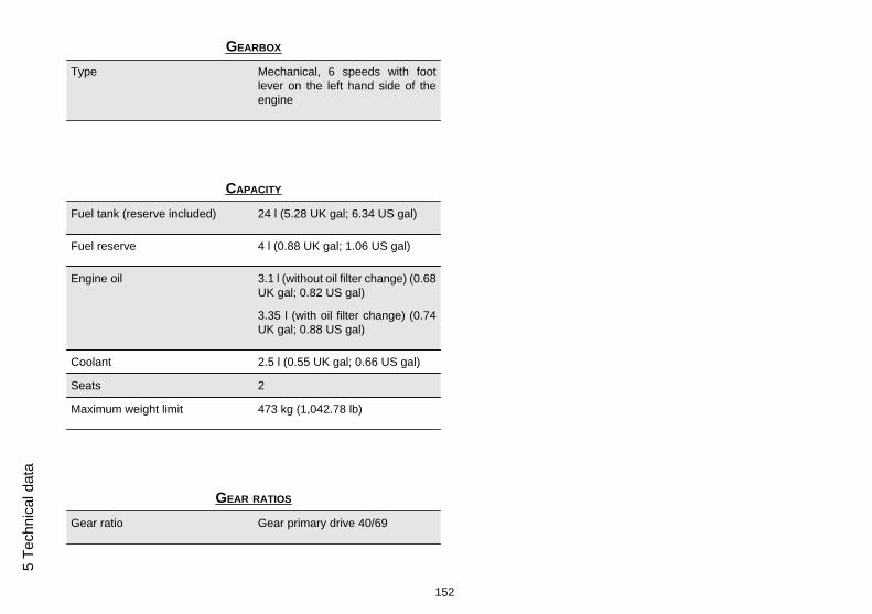
GEARBOX
Type Mechanical, 6 speeds with footlever on the left hand side of theengine
CAPACITY
Fuel tank (reserve included) 24 l (5.28 UK gal; 6.34 US gal)
Fuel reserve 4 l (0.88 UK gal; 1.06 US gal)
Engine oil 3.1 l (without oil filter change) (0.68UK gal; 0.82 US gal)
3.35 l (with oil filter change) (0.74UK gal; 0.88 US gal)
Coolant 2.5 l (0.55 UK gal; 0.66 US gal)
Seats 2
Maximum weight limit 473 kg (1,042.78 lb)
GEAR RATIOS
Gear ratio Gear primary drive 40/69
152
5 Te
chni
cal d
ata

1st gear ratio 14/36 (secondary)
2nd gear ratio 17/32 (secondary)
3rd gear ratio 20/30 (secondary)
4th gear ratio 22/28 (secondary)
5th gear ratio 23/26 (secondary)
6th gear ratio 24/25 (secondary)
Final drive gear ratio 17/42
DRIVE CHAIN
Type Endless (without master link) andwith sealed links. No. of links 112
Model 525 ZRPK
FUEL SYSTEM
Type Electronic injection (Multipoint)
Throttle valve diameter Ø 52 mm (2.05 in)
153
5 Technical data
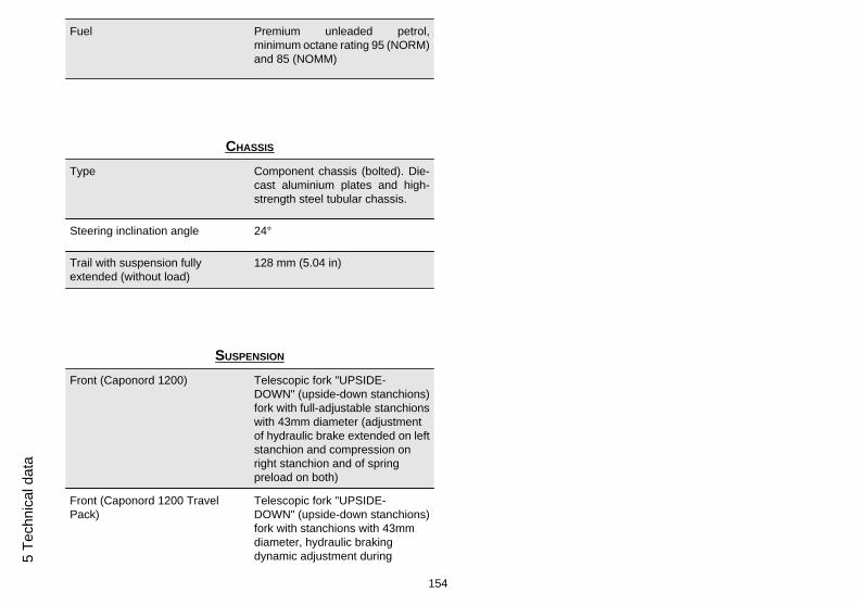
Fuel Premium unleaded petrol,minimum octane rating 95 (NORM)and 85 (NOMM)
CHASSIS
Type Component chassis (bolted). Die-cast aluminium plates and high-strength steel tubular chassis.
Steering inclination angle 24°
Trail with suspension fullyextended (without load)
128 mm (5.04 in)
SUSPENSION
Front (Caponord 1200) Telescopic fork "UPSIDE-DOWN" (upside-down stanchions)fork with full-adjustable stanchionswith 43mm diameter (adjustmentof hydraulic brake extended on leftstanchion and compression onright stanchion and of springpreload on both)
Front (Caponord 1200 TravelPack)
Telescopic fork "UPSIDE-DOWN" (upside-down stanchions)fork with stanchions with 43mmdiameter, hydraulic brakingdynamic adjustment during
154
5 Te
chni
cal d
ata

extension and compression (semi-active Aprilia Dynamic Dampingtechnology) on left stanchion; andof spring preload on rightstanchion, manually adjustable
Travel 170 mm (6.69 in)
Rear (Caponord 1200) Oscillating swingarm connectedwith cantilever type link to a Sachssingle shock absorber, withadjustment of hydraulic brakingduring extension and springpreload with knob.
Rear (Caponord 1200 Travel Pack) Oscillating swingarm connectedwith cantilever type link to a Sachssingle shock absorber, withadjustment of hydraulic brakingduring extension and compression(semi-active Aprilia DynamicDamping technology) with "piggy-back" tank and automatedmanagement (or manually oninstrument panel) of spring preloadvia electro-hydraulic system.
Wheel travel 150 mm (5.90 in)
BRAKES
Front Double floating disc, Ø 320 mm(12.60 in), radially-mounted
155
5 Technical data

calliper with four Ø 32 mm (1.26 in)pistons and two calliper pads
Rear 240 mm (9.45 in) diam. disc brakewith 35 mm (1.38 in) diam. singlepiston calliper
WHEEL RIMS
Type Light alloy rims with extractablebolt
Front 3.50 x 17"
Rear 6.00 x 17"
TYRES
Tyre type (standard) DUNLOP QUALIFIER II
(*) Only for 78 kW - PIRELLIANGEL GT versions
Front tyre 120/70 ZR17" (58W)
Front tyre pressure rider only: 2.4 bar (240 kPa) (34.81PSI)
rider + passenger: 2.5 bar (250kPa) (36.26 PSI)
156
5 Te
chni
cal d
ata

Rear tyre 180/55 ZR17" (73W)
190/55 ZR17" (75W) (*)
Rear tyre pressure rider only: 2.6 bar (260 kPa) (37.71PSI)
rider + passenger: 2.8 bar (280kPa) (40.61 PSI)
SPARK PLUGS
Standard spark plugs NGK CR8EKB
Spark plug electrode gap 0.6 - 0.7 mm (0.024 - 0.028 in)
Resistance 5 kOhm
ELECTRICAL SYSTEM
Battery VTX14-BS 12 V - 12 Ampere/hour
Main fuses 30A
Auxiliary fuses 7.5 A; 10 A; 15 A
Alternator (permanent magnettype)
13 V - 690 W at 6,000 rpm
157
5 Technical data

BULBS
Low-/ high beam light 12V - 55W H11
Front daylight running lights 12V - 5W
Turn indicators 12V - 10W (White light)
Rear daylight running light / stoplight
LED
Licence plate light 12V - 5W
Multifunction display lighting LED
WARNING LIGHTS
Turn indicators LED
High beam light LED
Fuel reserve LED
Cruise control warning light LED
Gear in neutral LED
General warning LED
ABS LED
ATC LED
158
5 Te
chni
cal d
ata

05_01
Kit equipment (05_01)
The tools supplied are:
• 3; 4; 5; 6 mm (0.12 0.16 0.20 0.24 in) L-shaped hex Allen keys (1);• One 10 - 13 mm (0.39 - 0.51 in) double open ended spanner (2);• Pliers to extract fuses (3);• Double ended Phillips/hexagonal screwdriver (4);• Toolkit pouch (5);
Maximum weight allowed: 1.5 kg (3.3 lb)
159
5 Technical data

160
5 Te
chni
cal d
ata

CAPONORD
Chap. 06Programmedmaintenance
161

Scheduled maintenance table
Correct maintenance is fundamental for ensuring the longevity of your vehicle andmaintaining optimum function and performance.
To this end, Aprilia offers a set of checks and maintenance services (at the owner'sexpense), that are summarised in the table shown on the following page. Any minorfaults must be reported without delay to an Authorised Aprilia Dealer or Sub-Deal-er without waiting until the next scheduled service to solve it.
All scheduled services must be carried out at the specified intervals and mileage, assoon as the predetermined mileage is reached. Carrying out scheduled services ontime is essential for the validity of your warranty. For further information regardingWarranty procedures and ''Scheduled Maintenance'', please refer to the ''WarrantyBooklet''.
NOTE
CARRY OUT MAINTENANCE OPERATIONS AT HALF THE INTERVALS SPECI-FIED IF THE VEHICLE IS USED IN PARTICULAR RAINY OR DUSTY CONDI-TIONS, OFF ROAD OR FOR TRACK USE.
I: INSPECT AND CLEAN, ADJUST, LUBRICATE OR REPLACE IF NECESSARY
C: CLEAN, R: REPLACE, A: ADJUST, L: LUBRICATE
(1) Replace at whichever of the following occurs first: 40,000 km (24854 mi) or 48months
(2) Replace every 2 years or 50,000 Km (31068 mi).
(3) Replace every 4 years
(4) At each engine start
(5) Check every month
(6) Check each time the rear tyre is replaced
162
6 Pr
ogra
mm
ed m
aint
enan
ce

(7) Lubricate if you are riding in the rain, on wet roads or after the vehicle has beenwashed
ROUTINE MAINTENANCE TABLE
km x 1,000 1 10 20 30 40
Rear shock absorber I I
Spark plug R R
Drive chain (7) I I I I I
Transmission cables and controls I I I
Steering bearings and steeringclearance I I I
Wheel bearings I I
Control unit diagnosis I I I
Brake discs I I I
Air filter I R I R
Engine oil filter R R R
Fork I I
General vehicle operation I I I
Valve clearance A A
Cooling system I I
Braking systems I I I
Light circuit I I I
Safety switches I I
163
6 Programm
ed maintenance
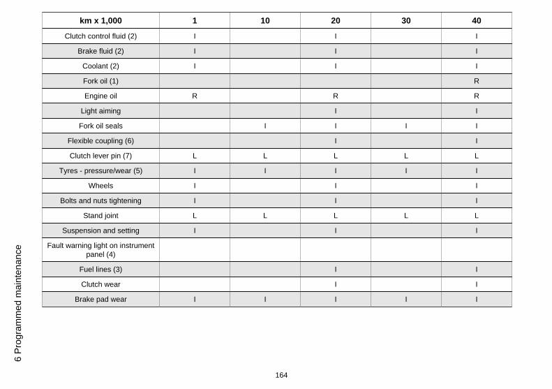
km x 1,000 1 10 20 30 40
Clutch control fluid (2) I I I
Brake fluid (2) I I I
Coolant (2) I I I
Fork oil (1) R
Engine oil R R R
Light aiming I I
Fork oil seals I I I I
Flexible coupling (6) I I
Clutch lever pin (7) L L L L L
Tyres - pressure/wear (5) I I I I I
Wheels I I I
Bolts and nuts tightening I I I
Stand joint L L L L L
Suspension and setting I I I
Fault warning light on instrumentpanel (4)
Fuel lines (3) I I
Clutch wear I I
Brake pad wear I I I I I
164
6 Pr
ogra
mm
ed m
aint
enan
ce

RECOMMENDED PRODUCTS TABLE
Product Description Specifications
ENI i-RIDE PG 15W-50 Engine oil Use branded oils with performance equivalentto or exceeding API SJ, JASO MA - ACEA A3- JASO MA2 specifications.
FUCHS TITAN SAF 1091 Fork oil (Caponord 1200) -
OJ RACING FORK OIL TYPE 01 Fork oil (Caponord 1200 Travel Pack) -
FUCHS TITAN SAF 1091 Actuator oil of the active rear single shockabsorber (Caponord 1200 Travel Pack)
-
AGIP MP GREASE Black smooth textured lithium-calcium soapbased grease containing EP (extremepressure) additives with optimal water-repellent properties
ISO L-X-BCHB 2 - DIN 51 825 KP2K-20
AGIP CHAIN LUBE SPRAY Spray lubricating grease -
AGIP BRAKE 4 Brake / Clutch fluid SAE J 1703 -FMVSS 116 - DOT 3/4 - ISO 4925- CUNA NC 956 DOT 4 synthetic fluid
AGIP PERMANENT SPECIAL Ethylene glycol-based antifreeze fluid withorganic inhibition additives. Red, ready to use.
ASTM D 3306 - ASTM D 4656 - ASTM D 4985- CUNA NC 956-16
165
6 Programm
ed maintenance

166
6 Pr
ogra
mm
ed m
aint
enan
ce

TABLE OF CONTENTS
AABS: 57Accessories: 70Air filter: 117Alarms: 38
BBattery: 16, 121, 122Brake: 15, 119, 136
CChain: 144–146Clutch: 15, 87, 120, 121Clutch fluid: 15, 120, 121Clutch lever: 87coolant: 14Coolant: 14
DDisc brake: 136
Display: 29
EEngine oil: 15, 112–114Engine stop: 54
FFork: 84Fuel: 12Fuses: 125
GGearbox oil: 15
HHeadlight: 131Horn: 50
IIdentification: 69Immobilizer: 65Instrument panel: 27
MMaintenance: 111, 161, 162Maintenance Table: 162Mirrors: 135
OOil filter: 114
Rrear-view mirrors: 135Ride by wire: 92
SSaddle: 66
Scheduled maintenance:162Shock absorbers: 80, 82Spark plug: 116Stand: 16, 103Start-up: 54Stop switch: 54
TTechnical data: 149Transmission: 144Turn indicators: 134Tyres: 115
WWarning lights: 13
167

THE VALUE OF SERVICE
As a result of continuous updates and specific technical training programmes for Aprilia products, only Aprilia Official Network mechanics know this vehicle fully and have the specific tools necessaryto carry out maintenance and repair operations correctly.
The reliability of the vehicle also depends on its mechanical conditions. Checking the vehicle before riding it, its regular maintenance and the use of original Aprilia spare parts only are essential factors!
For information on the nearest Official Dealer and/or Service Centre consult our website:
www.aprilia.com
Only by requesting Aprilia original spare parts can you be sure of purchasing products that were developed and tested during the actual vehicle design stage. All Aprilia original spare parts undergoquality control procedures to guarantee reliability and durability.
The descriptions and images in this publication are given for illustrative purposes only and are not binding.
While the basic characteristics as described and illustrated in this booklet remain unchanged, Piaggio & C. S.p.A. reserves the right, at any time and without being required to update this publicationbeforehand, to make any changes to components, parts or accessories, which it considers necessary to improve the product or which are required for manufacturing or construction reasons.
Not all versions/models shown in this publication are available in all countries. The availability of individual models should be confirmed with the official Aprilia sales network.
The Aprilia trademark is the property of Piaggio & C. S.p.A.
© Copyright 2014 - Piaggio & C. S.p.A. All rights reserved. Reproduction of this publication in whole or in part is prohibited.
Piaggio & C. S.p.A. Viale Rinaldo Piaggio, 25 - 56025 PONTEDERA (PI), Italy
www.piaggio.com