2013 isuzu truck isuzu truck.1 2013 isuzu truck ... chassis curb weight and gvw rating is located on...
TRANSCRIPT
2013 Isuzu Truck .1
2013 Isuzu Truck
PAG
E
5
WEIGHT DISTRIBUTION CONCEPTSWeight Restrictions
The Gross Vehicle Weight Rating (GVWR) and the Gross Axle Weight Rating (GAWR) of each Incomplete Vehicle are specifi ed on the cover of its Incomplete Vehicle Document in conformance to the requirements of Part 568.4 of the Federal Motor Vehicle Safety Regulations. The fi nal stage manufacturer is responsible under Part 567.5 to place the GVWR and the GAWR of each axle on the Final Vehicle Certifi cation Label. The regulation states that the appropriate rating “shall not be less than the sum of the unloaded vehicle weight, rated cargo load, and 150 pounds times the vehicle’s designated seating capacity.”
Unloaded vehicle weight means the weight of a vehicle with maximum capacity of all fl uids necessary for operation of the vehicle, but without cargo or occupants.
During completion of this vehicle, GVWR and GAWR may be affected in various ways, including but not limited to the following:
1. The installation of a body or equipment that exceeds the rated capacities of this Incomplete Vehicle.
2. The addition of designated seating positions which exceeds the rated capacities of this Incomplete Vehicle.
3. Alterations or substitution of any components such as axles, springs, tires, wheels, frame, steering and brake systems that may affect the rated capacities of this Incomplete Vehicle.
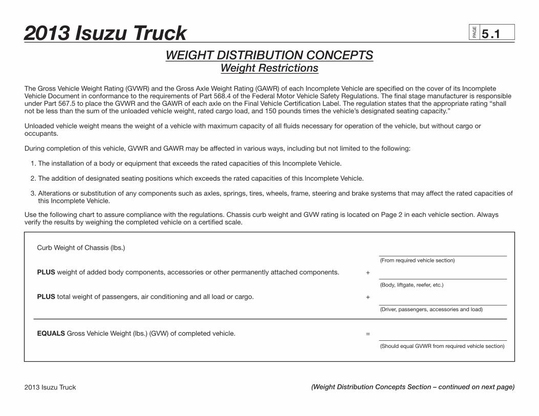
Use the following chart to assure compliance with the regulations. Chassis curb weight and GVW rating is located on Page 2 in each vehicle section. Always verify the results by weighing the completed vehicle on a certifi ed scale.
Curb Weight of Chassis (lbs.)
(From required vehicle section)
PLUS weight of added body components, accessories or other permanently attached components. +
(Body, liftgate, reefer, etc.)
PLUS total weight of passengers, air conditioning and all load or cargo. +
(Driver, passengers, accessories and load)
EQUALS Gross Vehicle Weight (lbs.) (GVW) of completed vehicle. =
(Should equal GVWR from required vehicle section)
(Weight Distribution Concepts Section – continued on next page)
2013 Isuzu Truck .2PAG
E
2013 Isuzu Truck
5(Weight Distribution Concepts Section – continued from previous page)
(Weight Distribution Concepts Section – continued on next page)
Gross Axle Weight RatingThe Gross Vehicle Weight is further restricted by the Gross AxIe Weight Rating (GAWR). The maximum GAWR for both front and rear axles is listed in each Vehicle Section. Weight distribution calculations must be performed to ensure GAWR is not exceeded. Always verify the results by weighing the completed vehicle on a certifi ed scale.
NOTE: Although the Front Gross Axle Weight Rating (FGAWR) plus the Rear Gross Axle Weight Rating (RGAWR) may exceed the Gross Vehicle Weight Rating (GVWR), the total GVW may not exceed the respective maximum GVWR.
The variation in the GAWRs allow the second stage manufacturer some fl exibility in the design of the weight distribution of the attached unit.
Weighing the VehicleFront and rear GAWRs and total GVWR should be verifi ed by weighing a completed loaded vehicle. Weigh the front and rear of the vehicle separately and combine the weights for the total GVWR. All three weights must be less than the respective maximum shown in the vehicle sections.
Tire Infl ationTire infl ation must be compatible with GAWR and GVWR as specifi ed on the cover of the Incomplete Vehicle Document for each vehicle.
Center of GravityThe design of the truck body should be such that the center of gravity of the added load does not exceed the guidelines as listed in each Vehicle Section. If the body is mounted in such a way that the center of gravity height exceeds the maximum height of the center of gravity designated for each model, the directional stability at braking and roll stability at cornering will be adversely affected. A vertical and/or horizontal center of gravity calculation must be performed if a question in stability arises to ensure the designed maximum height of the center of gravity is not violated.
2013 Isuzu Truck .3
2013 Isuzu Truck
PAG
E
5(Weight Distribution Concepts Section – continued from previous page)
(Weight Distribution Concepts Section – continued on next page)
Weight DistributionA truck as a commercial vehicle has but one purpose. That purpose is to haul some commodity from one place to another. A short distance or a long distance, the weight to be hauled, more than any other factor, determines the size of the truck. A small weight requires only a small truck; a large weight requires a large truck. A simple principle, but it can easily be misapplied. In any case, selecting the right size truck for the load to be hauled will ensure that the job will be done and that it will be able to be done with some degree of reliability and within the legal limitations of total gross weight and axle gross weights.
Not only must a truck be selected that will handle the total load, but the weight must also be properly distributed between the axles. This is of extreme importance from both a functional and economic aspect. If a truck consistently hauls less than its capacity, the owner is not realizing full return on his investment and his operating costs will be higher than they should be. If the truck is improperly loaded or overloaded, profi ts will be reduced due to increased maintenance costs and potential fi nes resulting from overloading beyond legal limitations. Careful consideration must be given to distribution of the load weight in order to determine how much of the total, including chassis, cab, body and payload, will be carried on the front axle and how much will be carried on the rear axle, on the trailer axles and the total. Moving a load a few inches forward or backward on the chassis can mean the difference between acceptable weight distribution for the truck or an application that will not do the job satisfactorily.
Every truck has a specifi c capacity and should be loaded so that the load distribution is kept within Gross Axle Weight Ratings (GAWR) and the truck’s Gross Vehicle Weight Rating (GVWR) or Gross Combination Weight Rating (GCWR) for a tractor/trailer and the weight laws and regulations under which the truck will operate. Improper weight distribution will cause problems in many areas:
1. Excessive front end wear and failure
a. Tie-rod and kingpin wear
b. Front axle failure
c. Overloading of front suspension
d. Wheel bearing failure
2. Rapid tire wear
a. When the weight on a tire exceeds its rating capacity, accelerated wear will result and could result in tire failure.
2013 Isuzu Truck .4PAG
E
2013 Isuzu Truck
5(Weight Distribution Concepts Section – continued from previous page)
(Weight Distribution Concepts Section – continued on next page)
3. Rough, erratic ride
a. If the center of the payload is directly over or slightly behind the rear axle, the lack of suffi cient weight on the front axle will create a bobbing effect, very rough ride, and erratic steering. This condition will be magnifi ed when the truck is going uphill.
4. Hard steering
a. When loads beyond the capacity of the front axle are imposed upon it, the steering mechanism is also overloaded and hard steering will result.
b. Excessive overloading could result in steering component damage or failure.
5. Unsafe operating and conditions
a. Poor traction on the steering axle effects the safety of the driver and equipment, particularly on wet, icy and slippery surfaces. Experience indicates that approximately 30% of the total weight at the ground on a truck or tractor should be on the front axle with a low cab forward vehicle.
b. When a truck is overloaded, a dangerous situation may exist because minimum speeds cannot always be maintained, directional control may not be precise and insuffi cient braking capacity can cause longer than normal braking distances.
6. High maintenance costs
a. Improper weight distribution and overloading cause excessive wear and premature failure of parts. Additional stresses imposed on the frame by the misapplication of wheelbases may be instrumental in causing the frame to crack or break.
7. Noncompliance with weight laws and regulations
a. When there is the possibility that axle loads will exceed existing weight laws and regulations, careful weight distribution is necessary to provide a correct balance between front and rear axle loads and total load within legal limitations.
In this way, maximum payloads may be carried without exceeding legal limits. If the body is too long for a wheelbase, the center of the body and payload is placed directly over the rear axle. This places all the payload on the rear axles, resulting in overloading the rear tires, rear axle springs and wheel bearings and potentially exceeding the rear axle legal weight limit. The front axle is then carrying no part of the payload and is easily lifted off the ground when going over rough terrain, creating a very rough ride and temporary loss of steering control. If the body is too short for the wheelbase used, frame stress may be increased and may result in excessive loads on the front axle. Excessive front axle loads increase wear on the kingpins and bushings, wheel bearings and steering gear. Excessive front axle loads also overstress the front axle, springs, tires and wheels. All of these contribute directly to higher maintenance costs and hard steering, both of which are undesirable.
2013 Isuzu Truck .5
2013 Isuzu Truck
PAG
E
5(Weight Distribution Concepts Section – continued from previous page)
(Weight Distribution Concepts Section – continued on next page)
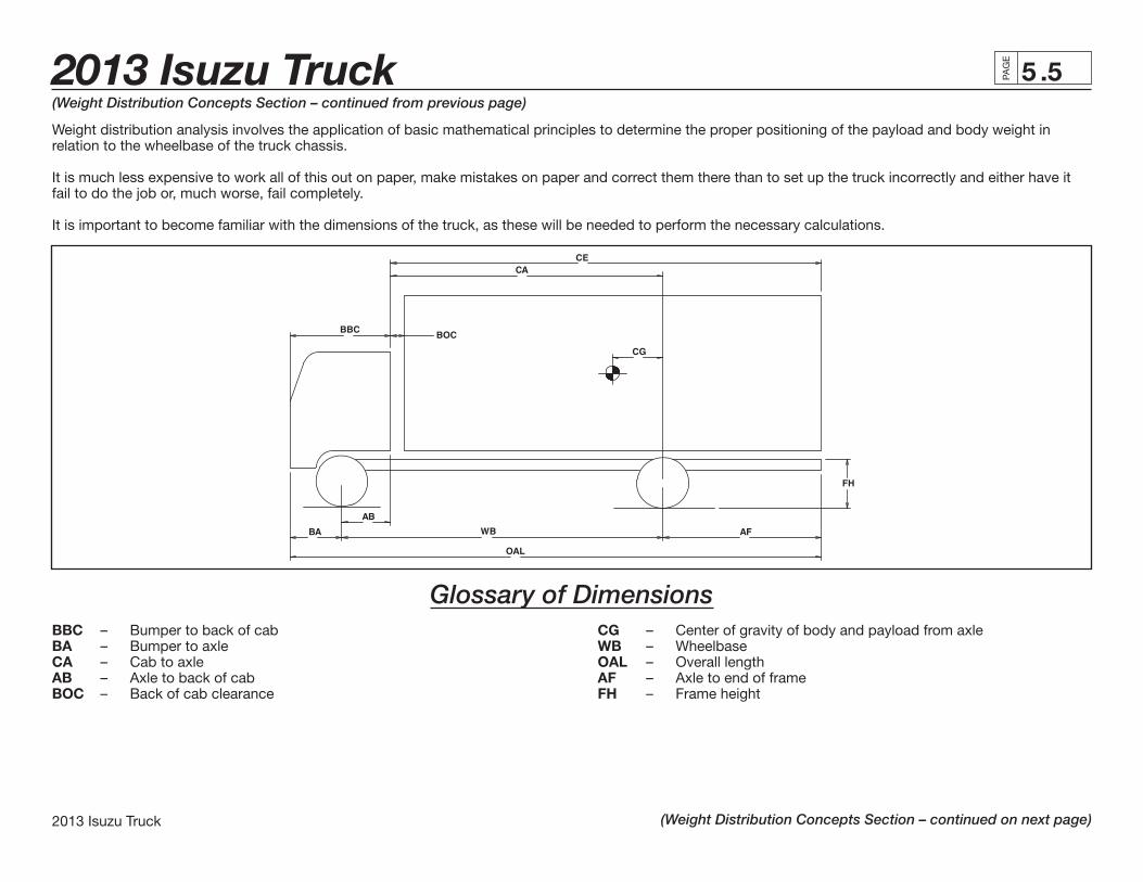
Weight distribution analysis involves the application of basic mathematical principles to determine the proper positioning of the payload and body weight in relation to the wheelbase of the truck chassis.
It is much less expensive to work all of this out on paper, make mistakes on paper and correct them there than to set up the truck incorrectly and either have it fail to do the job or, much worse, fail completely.
It is important to become familiar with the dimensions of the truck, as these will be needed to perform the necessary calculations.
Glossary of DimensionsBBC – Bumper to back of cab CG – Center of gravity of body and payload from axleBA – Bumper to axle WB – WheelbaseCA – Cab to axle OAL – Overall lengthAB – Axle to back of cab AF – Axle to end of frameBOC – Back of cab clearance FH – Frame height
2013 Isuzu Truck .6PAG
E
2013 Isuzu Truck
5(Weight Distribution Concepts Section – continued from previous page)
(Weight Distribution Concepts Section – continued on next page)
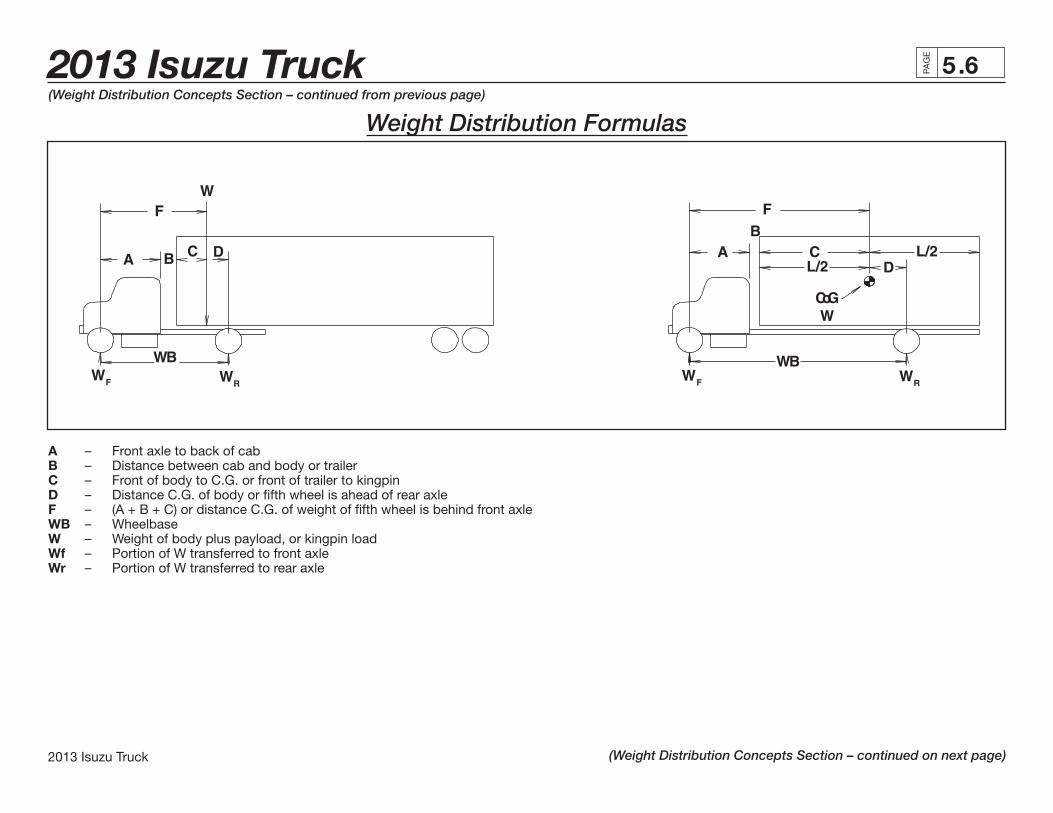
A – Front axle to back of cabB – Distance between cab and body or trailerC – Front of body to C.G. or front of trailer to kingpinD – Distance C.G. of body or fi fth wheel is ahead of rear axleF – (A + B + C) or distance C.G. of weight of fi fth wheel is behind front axleWB – WheelbaseW – Weight of body plus payload, or kingpin loadWf – Portion of W transferred to front axleWr – Portion of W transferred to rear axle
Weight Distribution Formulas

2013 Isuzu Truck .7
2013 Isuzu Truck
PAG
E
5(Weight Distribution Concepts Section – continued from previous page)
(Weight Distribution Concepts Section – continued on next page)
Basic Formulas (a) W x D = Wf x WB (c) WB = (A + B + C + D) = (F + D) or (b) W x F = Wr x WB (d) W = Wf x Wr
1. Wf = W x D 5. Wr = W x F WB WB
2. D = Wf x WB 6. F = Wr x WB W W
3. WB = W x D 7. WB = W x F Wf Wr
4. W = Wf x WB 8. W = Wr x WB D F
Weight Distribution Formulas in WordsTo fi nd:
1. Weight transferred to front axle = (Total weight) x (Distance C.G. is ahead of the rear axle) (Wheelbase)
2. Distance C.G. must be placed ahead of rear axle = (Weight transferred to the front axle) x (Wheelbase) (Total weight)
3. Wheelbase = (Total weight) x (Distance C.G. is ahead of the rear axle) (Weight to be transferred to the front axle)
4. Total Weight = (Weight to be transferred to the front axle) x (Wheelbase) (Distance C.G. is ahead of the rear axle)
2013 Isuzu Truck .8PAG
E
2013 Isuzu Truck
5
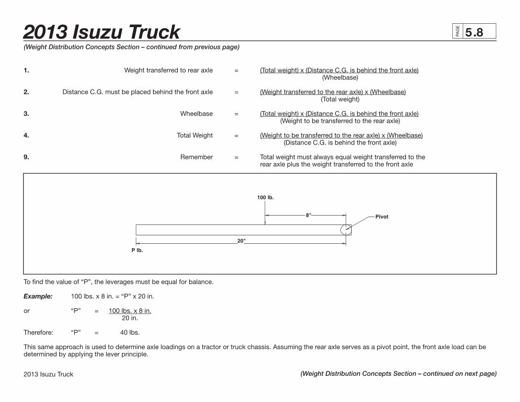
1. Weight transferred to rear axle = (Total weight) x (Distance C.G. is behind the front axle) (Wheelbase)
2. Distance C.G. must be placed behind the front axle = (Weight transferred to the rear axle) x (Wheelbase) (Total weight)
3. Wheelbase = (Total weight) x (Distance C.G. is behind the front axle) (Weight to be transferred to the rear axle)
4. Total Weight = (Weight to be transferred to the rear axle) x (Wheelbase) (Distance C.G. is behind the front axle)
9. Remember = Total weight must always equal weight transferred to the rear axle plus the weight transferred to the front axle
To fi nd the value of “P”, the leverages must be equal for balance.
Example: 100 lbs. x 8 in. = “P” x 20 in.
or “P” = 100 lbs. x 8 in. 20 in.
Therefore: “P” = 40 lbs.
This same approach is used to determine axle loadings on a tractor or truck chassis. Assuming the rear axle serves as a pivot point, the front axle load can be determined by applying the lever principle.
(Weight Distribution Concepts Section – continued from previous page)
(Weight Distribution Concepts Section – continued on next page)

2013 Isuzu Truck .9
2013 Isuzu Truck
PAG
E
5(Weight Distribution Concepts Section – continued from previous page)
(Weight Distribution Concepts Section – continued on next page)
Front Axle Load: = Kingpin Load x 5th Wheel Location Wheelbase
Rear Axle Load: = Kingpin Load – Front Axle Load
Example: (4) A tractor has a wheelbase of 150 inches. If the kingpin load is 20,000 lbs. and the fi fth wheel location is 15 inches, fi nd the total weight on the front and rear axles. The tare weight of the tractor is 7,000 lbs. on the front axle and 4,400 lbs. on the rear axle.
Front Axle = Load 20,000 x 15 = 2,000 lbs. 150 WB
Rear Axle Load = 20,000 – 2,000 lbs. = 18,000 lbs.
Therefore:Total Front Axle Weight = 2,000 + 9,000 lbs. = 11,000 lbs.Total Rear Axle Weight = 4,400 + 18,000 lbs. = 22,400 lbs.
2013 Isuzu Truck .10PAG
E
2013 Isuzu Truck
5(Weight Distribution Concepts Section – continued from previous page)
(Weight Distribution Concepts Section – continued on next page)
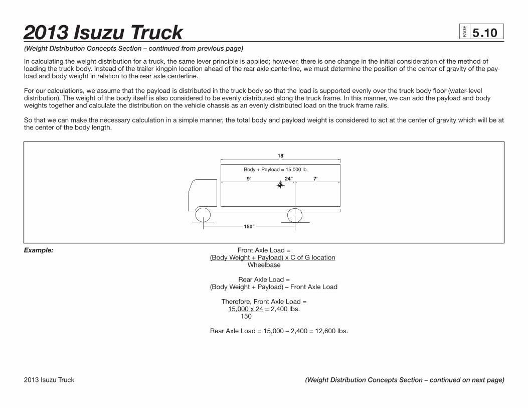
In calculating the weight distribution for a truck, the same lever principle is applied; however, there is one change in the initial consideration of the method of loading the truck body. Instead of the trailer kingpin location ahead of the rear axle centerline, we must determine the position of the center of gravity of the pay-load and body weight in relation to the rear axle centerline.
For our calculations, we assume that the payload is distributed in the truck body so that the load is supported evenly over the truck body fl oor (water-level distribution). The weight of the body itself is also considered to be evenly distributed along the truck frame. In this manner, we can add the payload and body weights together and calculate the distribution on the vehicle chassis as an evenly distributed load on the truck frame rails.
So that we can make the necessary calculation in a simple manner, the total body and payload weight is considered to act at the center of gravity which will be at the center of the body length.
Example: Front Axle Load = (Body Weight + Payload) x C of G location Wheelbase Rear Axle Load = (Body Weight + Payload) – Front Axle Load Therefore, Front Axle Load = 15,000 x 24 = 2,400 lbs. 150 Rear Axle Load = 15,000 – 2,400 = 12,600 lbs.

2013 Isuzu Truck .11
2013 Isuzu Truck
PAG
E
5(Weight Distribution Concepts Section – continued from previous page)
(Weight Distribution Concepts Section – continued on next page)
If the truck tare weight without the body is 5,000 lbs. on the front axle and 2,400 lbs. on the rear axle, then Total Front Axle Weight = 5,000 + 2,400 = 7,400 lbs. and Total Rear Axle Weight = 2,400 + 12,600 = 15,000 lbs.
This same lever principle is applied in all calculations of weight distribution, whether we are dealing with concentrated loads as with a kingpin load acting on a fi fth wheel or if it be with an evenly distributed load as with a truck body. The same approach is made in calculating an evenly distributed load on a trailer.
In the case of a tractor/trailer or a tractor with a set of double or triple trailers, each unit is handled as a separated unit and then combined to determine the total.
This simple example illustrates how the principles are applied. Using the formulas, fi nd the weight distributed to each axle.
Front Weight Rear Weight
A. Wf = W x D A. Total Weight – WB
B. 300 x 24 B. 300 – 75 96
C. = 75 lbs. C. = 225 lbs.
The body manufacturer can provide the body length and weight, or actual measurements of the body may be taken with a tape. Generally, (D) is unknown. This you must fi nd logically, or with a tape measure.
2013 Isuzu Truck .12PAG
E
2013 Isuzu Truck
5(Weight Distribution Concepts Section – continued from previous page)
(Weight Distribution Concepts Section – continued on next page)
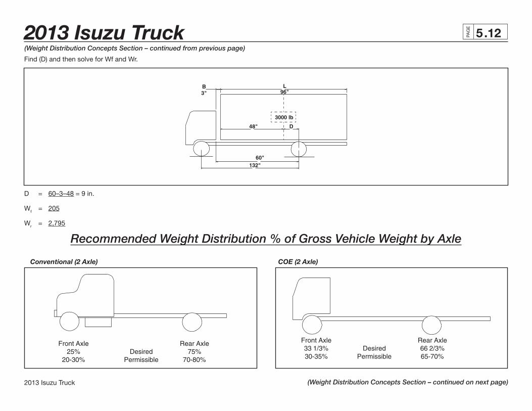
Find (D) and then solve for Wf and Wr.
D = 60–3–48 = 9 in.
Wf = 205
Wr = 2,795
Recommended Weight Distribution % of Gross Vehicle Weight by Axle
Conventional (2 Axle) COE (2 Axle)
2013 Isuzu Truck .13
2013 Isuzu Truck
PAG
E
5
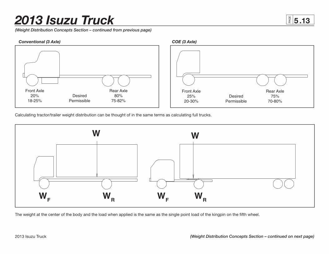
Conventional (3 Axle) COE (3 Axle)
(Weight Distribution Concepts Section – continued from previous page)
(Weight Distribution Concepts Section – continued on next page)
Calculating tractor/trailer weight distribution can be thought of in the same terms as calculating full trucks.
The weight at the center of the body and the load when applied is the same as the single point load of the kingpin on the fi fth wheel.

2013 Isuzu Truck .14PAG
E
2013 Isuzu Truck
5
In the following example, a 50,000-pound payload at water-level loading. Calculate the payload (PL) weight transfer to kingpin and the rear axle.
NOTE: Apply the same principles used with truck chassis.
Trailer Weight
(Weight Distribution Concepts Section – continued from previous page)
(Weight Distribution Concepts Section – continued on next page)

2013 Isuzu Truck .15
2013 Isuzu Truck
PAG
E
5(Weight Distribution Concepts Section – continued from previous page)
(Weight Distribution Concepts Section – continued on next page)
Payload at Kingpin
PLkp = W x D WB
Calculate the “D” dimension.
OAL/2 – AF = D 45 feet/2 – 48 inches – 36 inches = 186 inches
PLkp = 50,000 lbs. x 186 in. = 20,394 lbs. 456 in.
PLkp =20,394 lbs.
Payload at Rear Tandem
PLrt = W – PLkp
PLrt = 50,000 lbs. – 20,394 lbs. = 29,606 lbs.
PLrt = 29,606 lbs.
Once the weight on the kingpin is determined, it can then be treated on the tractor the same as a weight on a straight truck.
Due to the variations in hauling and wheelbase requirements from one truck application to another, there is no one specifi c fi fth wheel setting that will applyin all cases.
A “rule of thumb” which has proven satisfactory in many cases sets the fi fth wheel one inch ahead of the rear axle for every 10 inches of wheelbase. In the case of tandem axles, the wheelbase is measured from the center line of the front axle to the midpoint between the tandem rear axles. The location of the fi fth wheel fi xes the load distribution between the front and rear axles. Too far forward and the front axle is overloaded. If too far back, the front axle may be too lightly loaded and cause an unsafe steering and braking control situation at the front axle.

2013 Isuzu Truck .16PAG
E
2013 Isuzu Truck
5(Weight Distribution Concepts Section – continued from previous page)
(Weight Distribution Concepts Section – continued on next page)
A tractor on a hill with the fi fth wheel set at the axle center line or too close to it will result in an unsafe handling situation by transferring too much weight to the rear axle and actually unloading the front axle.
Performance CalculationsThe following calculations have been included to help you determine the performance characteristics required by your customers and to select the appropriate model vehicle:
1. Speed Formula
This formula can be used to determine:
1. Top speed of the vehicle.
2. Speed in a given gear.
3. Final ratio required for a given speed.
MPH @ Governed Speed = (60) x (RPM) (Rev/Mile) x (Gear Ratio)
2013 Isuzu Truck .17
2013 Isuzu Truck
PAG
E
5(Weight Distribution Concepts Section – continued from previous page)
(Weight Distribution Concepts Section – continued on next page)
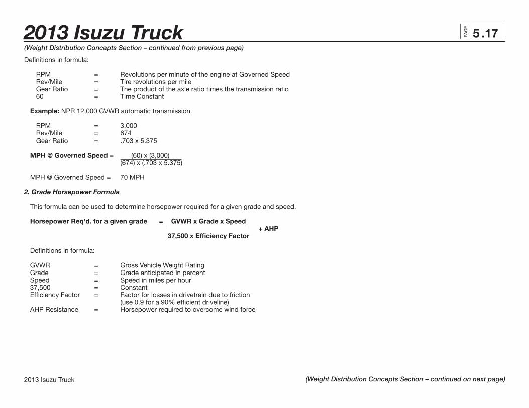
Defi nitions in formula:
RPM = Revolutions per minute of the engine at Governed Speed Rev/Mile = Tire revolutions per mile Gear Ratio = The product of the axle ratio times the transmission ratio 60 = Time Constant
Example: NPR 12,000 GVWR automatic transmission.
RPM = 3,000 Rev/Mile = 674 Gear Ratio = .703 x 5.375
MPH @ Governed Speed = (60) x (3,000) (674) x (.703 x 5.375)
MPH @ Governed Speed = 70 MPH
2. Grade Horsepower Formula
This formula can be used to determine horsepower required for a given grade and speed.
Horsepower Req’d. for a given grade = GVWR x Grade x Speed + AHP 37,500 x Effi ciency Factor
Defi nitions in formula:
GVWR = Gross Vehicle Weight Rating Grade = Grade anticipated in percent Speed = Speed in miles per hour 37,500 = Constant Effi ciency Factor = Factor for losses in drivetrain due to friction (use 0.9 for a 90% effi cient driveline) AHP Resistance = Horsepower required to overcome wind force

2013 Isuzu Truck .18PAG
E
2013 Isuzu Truck
5(Weight Distribution Concepts Section – continued from previous page)
(Weight Distribution Concepts Section – continued on next page)
Example: NPR 11,050 GVWR automatic transmission with a van body.
GVWR = 12,000 lbs. Grade = 1 percent Speed = 55 MPH 37,500 = Constant Effi ciency Factor = 0.9 AHP Resistance = 53.6 HP (see the following formula for calculation)
12,000 x 1 x 55 HP Required for Grade = + 53.67 37,500 x 0.9
HP Required for Grade = 73.22
3. Air Resistance Horsepower Formula
This formula is used to determine the horsepower required to overcome air resistance at a given speed.
Air Resistance Horsepower = FA x Cd x (MPH)3
156,000
Defi nitions in formula:
FA = Frontal area of vehicle in square feet Cd = Aerodynamic Drag Coeffi cient MPH = Speed of vehicle in miles per hour 156,000 = Constant
Frontal area is calculated by multiplying the height of the vehicle by the width of the vehicle and subtracting the open area under the vehicle from the total.
Aerodynamic Drag Coeffi cients (Source Material: Motor Truck Engineering Handbook):
0.70 for most trucks, semitrailer combinations with tanks or van bodies 0.77 for double and triple trailers and fl atbeds with loads

2013 Isuzu Truck .19
2013 Isuzu Truck
PAG
E
5(Weight Distribution Concepts Section – continued from previous page)
(Weight Distribution Concepts Section – continued on next page)
Example: NPR 12,000 GVWR van body with 96” wide, 115” high (84” body height + 31” frame height).
FA = (96) x (115) – 3.2 (12) x (12)
FA = 73.47 ft.2 Cd = 0.70 Speed = 55 mph
Air Resistance HP = 73.47 x 0.70 x (55)3 156,000
Air Resistance HP = 54.85
4. Engine Horsepower Formula
This formula can be used to derive the output at a given RPM and torque.
Horsepower = Torque x RPM 5,252
Defi nitions in formula:
Torque = Twisting output of engine given in lbs.-ft. RPM = Revolutions per minute of engine 5,252 = Constant
Example: NPR 12,000 GVWR automatic transmission.
Torque = 347 lbs.-ft. RPM = 2,000 132 HP = (347) x (2,000) 5,252

2013 Isuzu Truck .20PAG
E
2013 Isuzu Truck
5(Weight Distribution Concepts Section – continued from previous page)
(Weight Distribution Concepts Section – continued on next page)
5. Gradeability Formula
This formula can be used to determine how large of a grade a vehicle can climb.
Percent Grade = 1,200 x (T) x (E) x (C) x (R) – RR GVWR x r
Defi nitions in formula:
1,200 = Constant T = Maximum Torque of Engine E = Engine Effi ciency (0.9) C = Driveline Effi ciency (0.9) R = Transmission Ration x Axle Ratio RR = Rolling Resistance (see following chart) GVWR = Gross Vehicle Weight Rating r = Loaded radius of tire
Example: NPR 12,000 GVWR automatic transmission on concrete highway.
T = 347 lbs.-ft. E = 0.9 C = 0.9 R = .703 x 5.375 (in overdrive) RR = 1.0 GVWR = 12,000 r = 14.1 in.
Percent Grade = 1,200 x (347) x (0.9) x (0.9) x (.703) x (5.375) – 1.0 12,000 x 14.1
Percent Grade = 6.53 – 1
Gradeability = 5.53%

2013 Isuzu Truck .21
2013 Isuzu Truck
PAG
E
5(Weight Distribution Concepts Section – continued from previous page)
(Weight Distribution Concepts Section – continued on next page)
Road Rolling Resistance Road Rolling Resistance – Expressed in Percent Grade Road Surface Grade Road Surface Grade Concrete, excellent 1.0 Cobbles, ordinary 5.5 Concrete, good 1.5 Cobbles, poor 8.5 Concrete, poor 2.0 Snow, 2 inches 2.5 Asphalt, good 1.25 Snow, 4 inches 3.75 Asphalt, fair 1.75 Dirt, smooth 2.5 Asphalt, poor 2.25 Dirt, sandy 3.75 Macadam, good 1.5 Mud 3.75 to 15.0 Macadam, fair 2.25 Sand, level soft 6.0 to 15.0 Macadam, poor 3.75 Sand, dune 16.0 to 30.0
6. Startability Formula
This formula is used to determine what type of a grade a vehicle can be started on.
(1,200) x (CET) x (E) x (C) x (R) Startability = – 10% (GVWR x r) Defi nitions in formula:
1,200 = Constant CET = Clutch Engagement Torque E = 0.9 C = 0.9 R = Transmission x Axle Ratio 10% = Average break away resistance and static inertia constant GVWR = Gross Vehicle Weight Rating r = Loaded radius of tire
2013 Isuzu Truck .22PAG
E
2013 Isuzu Truck
5(Weight Distribution Concepts Section – continued from previous page)
(Weight Distribution Concepts Section – continued on next page)
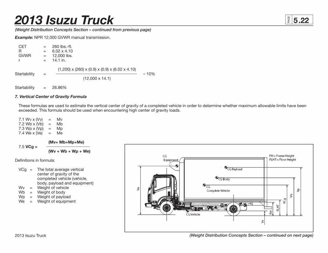
Example: NPR 12,000 GVWR manual transmission.
CET = 260 lbs.-ft. R = 6.02 x 4.10 GVWR = 12,000 lbs. r = 14.1 in.
(1,200) x (260) x (0.9) x (0.9) x (6.02 x 4.10)Startability = – 10% (12,000 x 14.1)
Startability = 26.86%
7. Vertical Center of Gravity Formula
These formulas are used to estimate the vertical center of gravity of a completed vehicle in order to determine whether maximum allowable limits have been exceeded. This formula should be used when encountering high center of gravity loads.
7.1 Wv x (Vv) = Mv 7.2 Wb x (Vb) = Mb 7.3 Wp x (Vp) = Mp 7.4 We x (Ve) = Me (Mv+ Mb+Mp+Me) 7.5 VCg = (Wv + Wb + Wp + We)
Defi nitions in formula:
VCg = The total average vertical center of gravity of the completed vehicle (vehicle, body, payload and equipment) Wv = Weight of vehicle Wb = Weight of body Wp = Weight of payload We = Weight of equipment
2013 Isuzu Truck .23
2013 Isuzu Truck
PAG
E
5
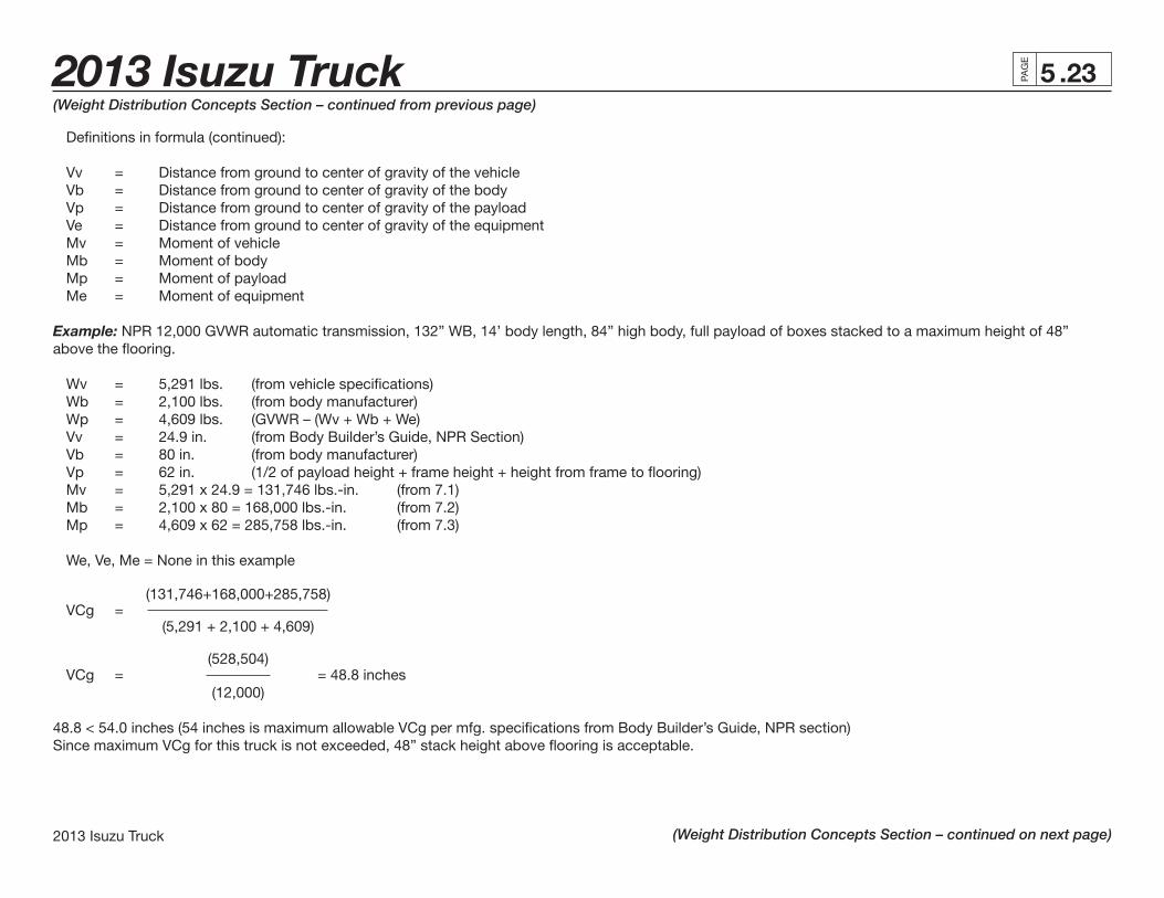
Defi nitions in formula (continued): Vv = Distance from ground to center of gravity of the vehicle Vb = Distance from ground to center of gravity of the body Vp = Distance from ground to center of gravity of the payload Ve = Distance from ground to center of gravity of the equipment Mv = Moment of vehicle Mb = Moment of body Mp = Moment of payload Me = Moment of equipment
Example: NPR 12,000 GVWR automatic transmission, 132” WB, 14’ body length, 84” high body, full payload of boxes stacked to a maximum height of 48” above the fl ooring.
Wv = 5,291 lbs. (from vehicle specifi cations) Wb = 2,100 lbs. (from body manufacturer) Wp = 4,609 lbs. (GVWR – (Wv + Wb + We) Vv = 24.9 in. (from Body Builder’s Guide, NPR Section) Vb = 80 in. (from body manufacturer) Vp = 62 in. (1/2 of payload height + frame height + height from frame to fl ooring) Mv = 5,291 x 24.9 = 131,746 lbs.-in. (from 7.1) Mb = 2,100 x 80 = 168,000 lbs.-in. (from 7.2) Mp = 4,609 x 62 = 285,758 lbs.-in. (from 7.3) We, Ve, Me = None in this example (131,746+168,000+285,758) VCg = (5,291 + 2,100 + 4,609) (528,504) VCg = = 48.8 inches (12,000)
48.8 < 54.0 inches (54 inches is maximum allowable VCg per mfg. specifi cations from Body Builder’s Guide, NPR section)Since maximum VCg for this truck is not exceeded, 48” stack height above fl ooring is acceptable.
(Weight Distribution Concepts Section – continued from previous page)
(Weight Distribution Concepts Section – continued on next page)

2013 Isuzu Truck .24PAG
E
2013 Isuzu Truck
5(Weight Distribution Concepts Section – continued from previous page)
(Weight Distribution Concepts Section – continued on next page)
8. Horizontal Center of Gravity Formula These formulas are used to estimate the horizontal center of gravity of a completed vehicle in order to determine whether it exists between the centerlines of the front and rear axles. This formula should be used when a load and/or permanent equipment (liftgate, reefer unit, snowplow, etc.) is installed on either extreme along the completed vehicle’s overall length.
8.1 Wv x (Hv) = Mv
8.2 Wb x (Hb) = Mb
8.3 Wp x (Hp) = Mp
8.4 We x (He) = Me
(Mv+Mb+Mp+Me) 8.5 HCg = (Wv + Wb + Wp + We)
Defi nitions in formula:
HCg = The total average horizontal center of gravity of the completed vehicle (vehicle, body, payload and equipment) Wv = Weight of vehicle Wb = Weight of body Wp = Weight of payload We = Weight of equipment Hv = Distance from front axle to center of gravity of the vehicle Hb = Distance from front axle to center of gravity of the body Hp = Distance from front axle to center of gravity of the payload He = Distance from front axle to center of gravity of the equipment Mv = Moment of vehicle Mb = Moment of body Mp = Moment of payload Me = Moment of equipment
2013 Isuzu Truck .25
2013 Isuzu Truck
PAG
E
5(Weight Distribution Concepts Section – continued from previous page)
(Weight Distribution Concepts Section – continued on next page)
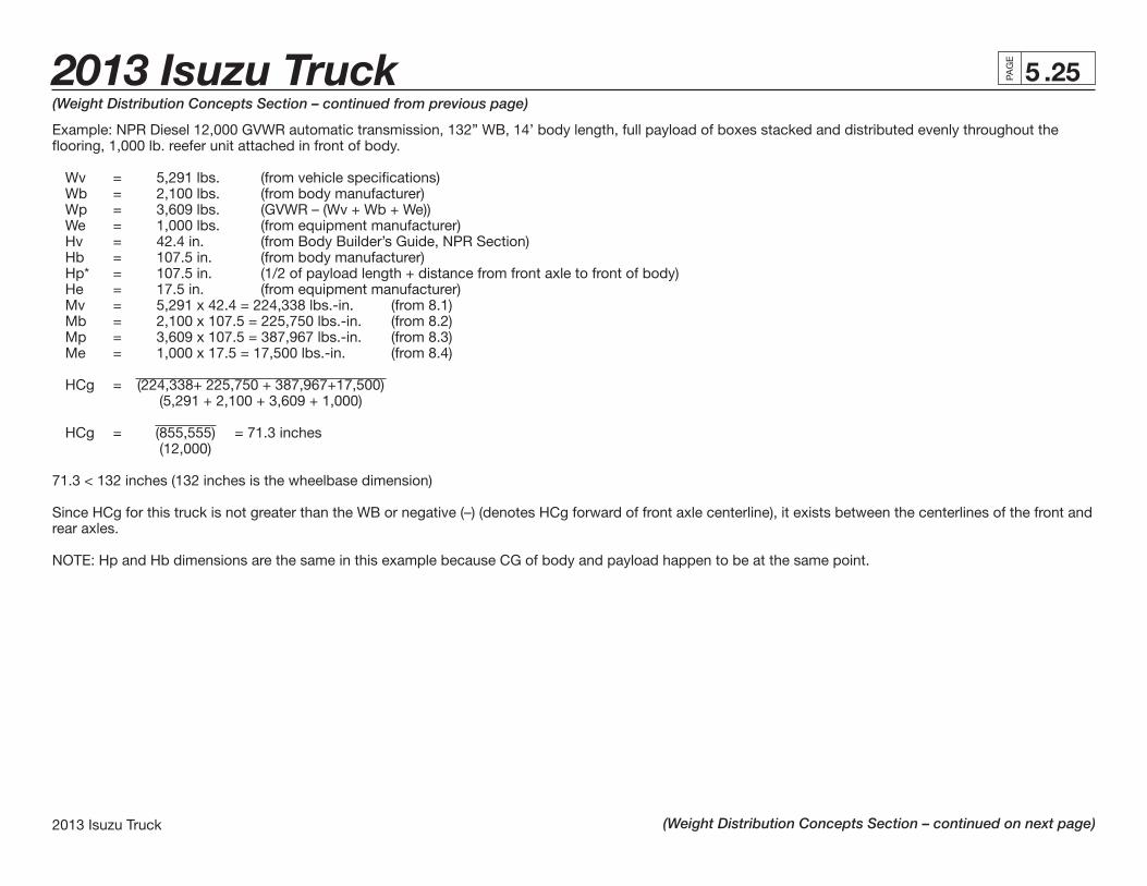
Example: NPR Diesel 12,000 GVWR automatic transmission, 132” WB, 14’ body length, full payload of boxes stacked and distributed evenly throughout the fl ooring, 1,000 lb. reefer unit attached in front of body. Wv = 5,291 lbs. (from vehicle specifi cations) Wb = 2,100 lbs. (from body manufacturer) Wp = 3,609 lbs. (GVWR – (Wv + Wb + We)) We = 1,000 lbs. (from equipment manufacturer) Hv = 42.4 in. (from Body Builder’s Guide, NPR Section) Hb = 107.5 in. (from body manufacturer) Hp* = 107.5 in. (1/2 of payload length + distance from front axle to front of body) He = 17.5 in. (from equipment manufacturer) Mv = 5,291 x 42.4 = 224,338 lbs.-in. (from 8.1) Mb = 2,100 x 107.5 = 225,750 lbs.-in. (from 8.2) Mp = 3,609 x 107.5 = 387,967 lbs.-in. (from 8.3) Me = 1,000 x 17.5 = 17,500 lbs.-in. (from 8.4) HCg = (224,338+ 225,750 + 387,967+17,500) (5,291 + 2,100 + 3,609 + 1,000) HCg = (855,555) = 71.3 inches (12,000)
71.3 < 132 inches (132 inches is the wheelbase dimension)
Since HCg for this truck is not greater than the WB or negative (–) (denotes HCg forward of front axle centerline), it exists between the centerlines of the front and rear axles.
NOTE: Hp and Hb dimensions are the same in this example because CG of body and payload happen to be at the same point.

2013 Isuzu Truck .26PAG
E
2013 Isuzu Truck
5
The Federal Government established the Federal Bridge Gross Weight Formula to provide a standard to control the spacing of truck axles on trucks that use highway bridges. This is intended to space loads out over a distance to avoid too high a concentration in one area that could cause damage. The truck’s gross weights, axle weight and axle spacings are set in order to keep axle loads and gross weight loads within the limits set by the Federal Government. The Bridge Formula Table is used to check trucks to make sure that Federal weight limit requirements are met and that the allowable gross and axle weights are in the cor-rect relationship with the spacing of axles to prevent high load concentrations on highway bridges.
The Federal Government has established the following formula to be used to determine the allowable weight limits and axle spacings for trucks.
W = 500 (LN + 12N = 36) N-1
Where:
W = The total gross weight that may be carried on any group of two or more consecutive axles to the nearest 500 lbs.
L = The distance (spacing) in feet between the outer axles of any group of two or more consecutive axles.
N = The number of axles in the group under consideration; except that two consecutive sets of tandem axles may carry a gross load of
34,000 lbs. each provided the overall distance between the fi rst and last axles of such consecutive sets of axles is 36 feet or more.
Bridge Formula Defi nitions
The following defi nitions are used for bridge formula calculations.
Gross Weight
The total weight of a truck (and/or trailer) combined with the weight of the load being hauled. The Federal gross weight limits on interstate highways and federal-aid highways and reasonable access is 80,000 lbs.
Highway System Limits
(Weight Distribution Concepts Section – continued from previous page)
(Weight Distribution Concepts Section – continued on next page)
2013 Isuzu Truck .27
2013 Isuzu Truck
PAG
E
5
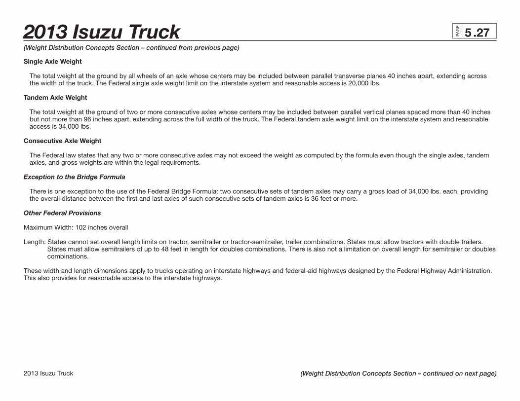
Single Axle Weight
The total weight at the ground by all wheels of an axle whose centers may be included between parallel transverse planes 40 inches apart, extending across the width of the truck. The Federal single axle weight limit on the interstate system and reasonable access is 20,000 lbs.
Tandem Axle Weight
The total weight at the ground of two or more consecutive axles whose centers may be included between parallel vertical planes spaced more than 40 inches but not more than 96 inches apart, extending across the full width of the truck. The Federal tandem axle weight limit on the interstate system and reasonable access is 34,000 lbs.
Consecutive Axle Weight
The Federal law states that any two or more consecutive axles may not exceed the weight as computed by the formula even though the single axles, tandem axles, and gross weights are within the legal requirements.
Exception to the Bridge Formula
There is one exception to the use of the Federal Bridge Formula: two consecutive sets of tandem axles may carry a gross load of 34,000 lbs. each, providing the overall distance between the fi rst and last axles of such consecutive sets of tandem axles is 36 feet or more.
Other Federal Provisions
Maximum Width: 102 inches overall
Length: States cannot set overall length limits on tractor, semitrailer or tractor-semitrailer, trailer combinations. States must allow tractors with double trailers. States must allow semitrailers of up to 48 feet in length for doubles combinations. There is also not a limitation on overall length for semitrailer or doubles combinations.
These width and length dimensions apply to trucks operating on interstate highways and federal-aid highways designed by the Federal Highway Administration. This also provides for reasonable access to the interstate highways.
(Weight Distribution Concepts Section – continued from previous page)
(Weight Distribution Concepts Section – continued on next page)

2013 Isuzu Truck .28PAG
E
2013 Isuzu Truck
5(Weight Distribution Concepts Section – continued from previous page)
(Weight Distribution Concepts Section – continued on next page)
Federal Bridge Formula Table Distance in feet between the Maximum Load in Pounds on Any Group of 2 or More Consecutive Axles extremes of any group of 2 or more consecutive axles 2 Axles 3 Axles 4 Axles 5 Axles 6 Axles 7 Axles 8 Axles 9 Axles 4 34,000* 5 34,000* 6 34,000* 7 34,000* 8 and less 34,000* 34,000 8 and more 38,000 42,000 9 39,000 42,500 10 40,000 43,500 11 44,000 12 45,000 50,000 13 45,500 50,500 14 46,500 51,500 15 47,000 52,000 16 48,000 52,500 58,000 17 48,500 53,500 58,500 18 49,500 54,000 59,000 19 50,000 54,500 60,000 20 51,000 55,500 60,500 66,000 21 51,500 56,000 61,000 66,500 22 52,500 56,500 61,500 67,000
* Tandem Axle by Defi nition. NOTE: All permissible load calculations are to the nearest 500 lbs. + Exception to Federal Bridge Formula Table and Law. See Text for Explanation. Maximum load on any single axle, 20,000 lbs. Weights over 80,000 lbs. are in excess of the Federal GVW on the National Highway Network.
2013 Isuzu Truck .29
2013 Isuzu Truck
PAG
E
5(Weight Distribution Concepts Section – continued from previous page)
(Weight Distribution Concepts Section – continued on next page)
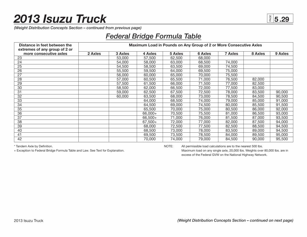
Federal Bridge Formula Table Distance in feet between the Maximum Load in Pounds on Any Group of 2 or More Consecutive Axles extremes of any group of 2 or more consecutive axles 2 Axles 3 Axles 4 Axles 5 Axles 6 Axles 7 Axles 8 Axles 9 Axles 23 53,000 57,500 62,500 68,000 24 54,000 58,000 63,000 68,500 74,000 25 54,500 58,500 63,500 69,000 74,500 26 55,500 59,500 64,000 69,500 75,000 27 56,000 60,000 65,000 70,000 75,500 28 57,000 60,500 65,500 71,000 76,500 82,000 29 57,500 61,500 66,000 71,500 77,000 82,500 30 58,500 62,000 66,500 72,000 77,500 83,000 31 59,000 62,500 67,500 72,500 78,000 83,500 90,000 32 60,000 63,500 68,000 73,000 78,500 84,500 90,500 33 64,000 68,500 74,000 79,000 85,000 91,000 34 64,500 69,000 74,500 80,000 85,500 91,500 35 65,500 70,000 75,000 80,500 86,000 92,000 36 66,000+ 70,500 75,500 81,000 86,500 93,000 37 66,500+ 71,000 76,000 81,500 87,000 93,500 38 67,500+ 72,000 77,000 82,000 87,500 94,000 39 68,000 72,500 77,500 82,500 88,500 94,500 40 68,500 73,000 78,000 83,500 89,000 94,500 41 69,500 73,500 78,500 84,000 89,500 95,000 42 70,000 74,000 79,000 84,500 90,000 95,500
* Tandem Axle by Defi nition. NOTE: All permissible load calculations are to the nearest 500 lbs. + Exception to Federal Bridge Formula Table and Law. See Text for Explanation. Maximum load on any single axle, 20,000 lbs. Weights over 80,000 lbs. are in excess of the Federal GVW on the National Highway Network.

2013 Isuzu Truck .30PAG
E
2013 Isuzu Truck
5(Weight Distribution Concepts Section – continued from previous page)
(Weight Distribution Concepts Section – continued on next page)
Federal Bridge Formula Table (Continued) Distance in feet between the Maximum Load in Pounds on Any Group of 2 or More Consecutive Axles extremes of any group of 2 or more consecutive axles 2 Axles 3 Axles 4 Axles 5 Axles 6 Axles 7 Axles 8 Axles 9 Axles 43 70,500 75,000 80,000 85,000 90,500 96,000 44 71,500 75,500 80,500 85,500 91,000 96,500 45 72,000 76,000 81,000 86,000 91,500 97,500 46 72,500 76,500 81,500 87,000 92,500 98,000 47 73,500 77,500 82,000 87,500 93,000 98,500 48 74,000 78,000 83,000 88,000 93,500 99,000 49 74,500 78,500 83,500 88,500 94,000 99,500 50 75,500 79,000 84,000 89,000 94,500 100,000 51 76,000 80,000 84,500 89,500 95,000 100,500 52 76,500 80,500 85,000 90,500 95,500 101,000 53 77,500 81,000 86,000 91,000 96,500 102,000 54 78,000 81,500 86,500 91,500 97,000 102,500 55 78,500 82,500 87,000 92,000 97,500 103,000 56 79,500 83,000 87,500 92,500 98,000 103,500 57 80,000 83,500 88,000 93,000 98,500 104,000 58 84,000 89,000 94,000 99,000 104,500 59 85,000 89,500 94,500 99,500 105,000 60 85,500 90,000 95,000 100,500 105,500
* Tandem Axle by Defi nition. NOTE: All permissible load calculations are to the nearest 500 lbs. + Exception to Federal Bridge Formula Table and Law. See Text for Explanation. Maximum load on any single axle, 20,000 lbs. Weights over 80,000 lbs. are in excess of the Federal GVW on the National Highway Network.