20120806 ch8 power monitor and management … 1 power monitor and management solution overview 8.1....
TRANSCRIPT

Power Monitor and Management Solution
8.1. Overview P8-1-1
● Introduction - - - - - - - - - - - - - - - - - - - - - - - - - - - - - - - - - - - - - - - - - - - - - - - - - - - - - P8-1-1
8.2. Power Meter Concentrator P8-2-1
● PMC-5141/PMC-5141P - - - - - - - - - - - - - - - - - - - - - - - - - - - - - - - - - - - - - - - - - - - - - - - P8-2-1
8.3. Smart Power Meter P8-3-1
● PM-2133 - - - - - - - - - - - - - - - - - - - - - - - - - - - - - - - - - - - - - - - - - - - - - - - - - - - - - - - P8-3-1
● PM-3112/PM-3114 - - - - - - - - - - - - - - - - - - - - - - - - - - - - - - - - - - - - - - - - - - - - - - - - - P8-3-3
● CT for Smart Power Meter - - - - - - - - - - - - - - - - - - - - - - - - - - - - - - - - - - - - - - - - - - - - P8-3-5
8.4. Voltage Attenuator P8-4-1
● DN-843V-600V/DN-848VI-10V/DN-848VI-80V/DN-848VI-150V - - - - - - - - - - - - - - - - - - - - - P8-4-1
8.5. Current Transformer P8-5-1
● DN-843I-CT-1/DN-843I-CT-10/DN-843I-CT-20/DN-843I-CT-50 - - - - - - - - - - - - - - - - - - - - - P8-5-1
ICP Electronics Australia Pty Ltd www.icp-australia.com.au 02 9457 6011
81
Pow
er M
onito
r an
d M
anag
emen
t So
lutio
nOverview
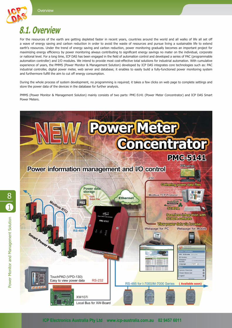
8.1. OverviewFor the resources of the earth are getting depleted faster in recent years, countries around the world and all walks of life all set off a wave of energy saving and carbon reduction in order to avoid the waste of resources and pursue living a sustainable life to extend earth's resources. Under the trend of energy saving and carbon reduction, power monitoring gradually becomes an important project for maximizing energy effi ciency by power monitoring always contributing to signifi cant energy savings no mater on the individual, corporate or national level. For a long time, ICP DAS has been engaged in the fi eld of automation control and developed a series of PAC (programmable automation controller) and I/O modules. We intend to provide most cost-effective total solutions for industrial automation. With cumulative experience of years, the PMMS (Power Monitor & Management Solution) developed by ICP DAS integrates core technologies such as: PAC industrial controller, digital power meter, web server and database; it enables to easily build a fully-functioned power monitoring system and furthermore fulfi ll the aim to cut off energy consumption.
During the whole process of system development, no programming is required; it takes a few clicks on web page to complete settings and store the power data of the devices in the database for further analysis.
PMMS (Power Monitor & Management Solution) mainly consists of two parts: PMC-5141 (Power Meter Concentrator) and ICP DAS Smart Power Meters.
( Available soon)
ICP Electronics Australia Pty Ltd www.icp-australia.com.au 02 9457 6011

Power M
onitor and Managem
ent Solution
8-1-2
Remote I/O Modules and I/O Expansion Units
81
1. Built-in Web Server
7. Immediately display power data in real-time trend or historical trend
8. Offer Flash HMI Tools on Webpage
2. Support data storage
3. Support FTP Server and FTP Client for easy fi le management
4. Offer Modbus TCP Slave function that allows seamless integration with SCADA software
5. Allow to integrate with an internal I/O module (XW107i)
6. Support Remote I/O modules for I/O expansion (Available Soon)
● Features
ICP Electronics Australia Pty Ltd www.icp-australia.com.au 02 9457 6011
82
Pow
er M
onito
r an
d M
anag
emen
t So
lutio
nPower Meter Concentrator
Applications
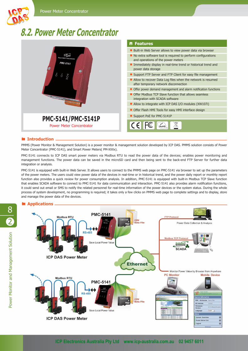
PMC-5141/PMC-5141PPower Meter Concentrator
Features Built-in Web Server allows to view power data via browser
No extra software tool is required to perform confi gurations and operations of the power meters
Immediately display in real-time trend or historical trend and power data storage
Support FTP Server and FTP Client for easy fi le management
Allow to recover Data Log fi les when the network is resumed after temporary network disconnection
Offer power demand management and alarm notifi cation functions
Offer Modbus TCP Slave function that allows seamless integration with SCADA software
Allow to integrate with ICP DAS I/O modules (XW107i)
Offer Flash HMI Tools for easy HMI interface design
Support PoE for PMC-5141P
PMMS (Power Monitor & Management Solution) is a power monitor & management solution developed by ICP DAS. PMMS solution consists of Power Meter Concentrator (PMC-5141), and Smart Power Meters( PM-XXXx).
PMC-5141 connects to ICP DAS smart power meters via Modbus RTU to read the power data of the devices; enables power monitoring and management functions. The power data can be saved in the microSD card and then being sent to the back-end FTP Server for further data integration or analysis.
PMC-5141 is equipped with built-in Web Server. It allows users to connect to the PMMS web page on PMC-5141 via browser to set up the parameters of the power meters. The users could view power data of the devices in real-time or in historical trend, and the power daily report or monthly report function also provides a quick review for power consumption analysis. In addition, PMC-5141 is equipped with built-in Modbus TCP Slave function that enables SCADA software to connect to PMC-5141 for data communication and interaction. PMC-5141 also provides alarm notifi cation functions, it could send out email or SMS to notify the related personnel for real-time information of the power devices or the system status. During the whole process of system development, no programming is required; it takes only a few clicks on PMMS web page to complete settings and to display, store and manage the power data of the devices.
Introduction
8.2. Power Meter Concentrator
ICP Electronics Australia Pty Ltd www.icp-australia.com.au 02 9457 6011

Remote I/O Modules and I/O Expansion Units
82
Power M
onitor and Managem
ent Solution
Appearance
VGA Port
USB ClientmicroSD Socket
Rotary Switch
LAN2 Pin AssigmentUSB Host
DNG
RWP
DxR
DxT+ D -D
DxR
DxT
COM1 COM2 COM3 DC+10~30V
.G.F101
DNG.P
Connect to Smart Power Meters
LED Indicators
LAN1(PoE Port for PMC-5141P)
Specifi cationsModel PMC-5141 PMC-5141PSystem Software
OS Windows CE 5.0 Core
.Net Compact Framework 3.5
Embedded Service Web server, FTP server
CPU Module
CPU PXA270 CPU (32-bit and 520 MHz)
SDRAM 128 MB
Flash 64 MB
EEPROM16 KB Data Retention: 40 years;
1,000,000 erase/write cycles
Expansion Flash MemorymicroSD socket with one 2 GB microSD card
(support up to 16 GB microSDHC card)
RTC (Real Time Clock) Provide second, minute, hour, date, day of week, month, year
LED Indicator 1 LED for Power and Running
Rotary Switch Yes (0 ~ 9)
VGA & Communication Ports
VGA Yes, Resolutions: 640 x 480/800 x 600
EthernetRJ-45 x 2, 10/100 Base-TX
(Auto-negotiating, Auto MDI/MDI-X, LED indicators)*Note: LAN1 is reserved for PMC-5141
USB 1.1 (client) 1
USB 1.1 (host)1
*Note: Connect to GTM-201-USB for SMS Function
COM 1 RS-232 (RxD, TxD and GND); non-isolated
COM 2RS-485 (D2+, D2-); 2500 VDC; isolated;
*Note: Allow to connect to up to 16 Smart Power Meters (Modbus RTU Interface)
COM 3 RS-232 (RxD, TxD and GND); non-isolated
Mechanical
Dimensions (W x L x H) 91 mm x 126 mm x 52 mm
Installation DIN-Rail Mounting
Environmental
Operating Temperature -25 ~ +75 °C
Storage Temperature -30 ~ +80 °C
Ambient Relative Humidity 10 ~ 90% RH (non-condensing)
Power
Input Range +10 ~ +30 VDC +12 ~ +48 VDC
Isolation 1 kV -
Consumption 4.8 W (0.2 A @ 24 VDC) 4.3 W (0.18 A @ 24 VDC)
Dimensions (Units: mm)
52
5242.591
126
Top ViewFront View Left Side View Right Side ViewBottom ViewRear View
Ordering InformationPMC-5141-EN CR Power Meter Concentrator (English) (RoHS) PMC-5141P-EN CR PMC-5141 with PoE (English) (RoHS) (Available soon)
PMC-5141-TC CR Power Meter Concentrator (Traditional Chinese) (RoHS) PMC-5141P-TC CR PMC-5141 with PoE (Traditional Chinese) (RoHS) (Available soon)
PMC-5141-SC CR Power Meter Concentrator (Simplifi ed Chinese) (RoHS) PMC-5141P-SC CR PMC-5141 with PoE (Simplifi ed Chinese) (RoHS) (Available soon)
Accessories
Smart Power Meter Currently support PM-2133-100, PM-2133-160, PM-2133-240, PM-311x-100, PM-311x-160, & PM-311x-240 (with RS-485 Interface)
DP-660 24 VDC/2.5 A, 60 W and 5 VDC/0.5 A, 2.5 W Power Supply with DIN-Rail Mounting
DP-1200 CR 24 VDC/5.0 A, 120 W Power Supply with DIN-Rail Mounting (RoHS)
MDR-20-24 CR 24 VDC/1.0 A, 24 W Power Supply with DIN-Rail Mounting (RoHS)
MDR-60-24 CR 24 VDC/2.5 A, 60 W Power Supply with DIN-Rail Mounting (RoHS)
GTM-201-USB Industrial Quad-band GPRS/GSM Modem with USB Interface (RoHS)
XW107i Add-on I/O Expansion Board (8 DI and 8 DO)
ICP Electronics Australia Pty Ltd www.icp-australia.com.au 02 9457 6011

83
Pow
er M
onito
r an
d M
anag
emen
t So
lutio
nSmart Power Meter
PM-21331 loop 3-phase Smart Power Meter
Features True RMS Power Measurements
Energy Analysis for 3P4W, 3P3W
Current Measurements Up to 200 A with Different CT Ratio
Voltage Measurements Up to 500 V
Clip-on CT for Easy Installation
kWh Accuracy Better than 1% (PF=1)
RS-485, Ethernet or CAN Bus Communication Interface
Modbus RTU, Modbus TCP or CANopen Protocol
It’s always diffi cult but crucial to the supervisors to fi gure out how much energy is consumed. ICP DAS brings the most powerful, cost effective, advanced Compact Power Meters, PM-2133, to the markets. With its high accuracy (1%, PF=1), the PM-2133 can be applied both on low voltage primary side and/or medium/high voltage secondary side and enable the users to obtain in real time the reliable and accurate energy consumption readings from the monitored equipments while in operation. These compact size and cost effective power meters are equipped with revolutionary wired clip-on CT (various types support input current up to 200A). It supports Modbus RTU, Modbus TCP or CANopen protocols for easy integration. It works with input voltages ranging 10 ~ 500 VAC, supports a wide range of applications.
Introduction
Specifi cations
Models PM-2133 PM-2133-MTCPPM-2133-CAN
PM-2133-CPSAC Power Measurement
Wiring 3P4W-3CT, 3P3W-3CT
Input Voltage 10 ~ 500 VAC
Input Current 60 A, 100 A, 200 A; with different CT ratio
Input Frequency 50/60 Hz
kWh Accuracy Better than 1% (PF=1)
Starting Current 0.025A
Power Parameter Measurement
True RMS voltage (Vrms), True RMS current (Irms),Active Power (kW), Active Energy (kWh),
Apparent Power (kVA), Apparent Energy (kVAh),Reactive Power (kVAR), Reactive Energy (kVARh), Power Factor (PF)
Data Update Rate 1 Second
Communication
RS-485
Protocol Modbus RTU - -
Baudrate 9600, 19200 (Default), 38400 - -
Data format N,8,1 - -
Isolation 1000 Vrms - -
EthernetProtocol - Modbus TCP -
Default IP - 192.168.255.1. -
CAN BusProtocol - - CAN or CANopen
Baudrate - - 125K (Default), 250K, 500K
Power
Input Range +10 ~ 30 VDC
Power Consumption 2.4 W
Mechanical
Casing Plastic
Flammability UL 94V-0 materials
Dimensions (W x L x H) 33 mm x 96 mm × 112 mm
Module Installation DIN-Rail Mounting
CT Installation Clip-On
Environment
Operating Temperature -10 ~ +70 ˚C
Storage Temperature -25 ~ +85 ˚C
Ambient Relative Humidity 10% ~ 90% RH, Non-condensing
8.3. Smart Power Meter
ICP Electronics Australia Pty Ltd www.icp-australia.com.au 02 9457 6011

Remote I/O Modules and I/O Expansion Units
83
Power M
onitor and Managem
ent Solution
Power IndicatorkWh Indicator
CAN Bus Communication Indicatorr
Appearance
Bottom View Top ViewLeft Side View Front View Rear ViewRight Side View
Dimensions (Units: mm)
33.0
107.0112.0
78.096.0
39.0
35.4
24.6
8.0
RS-485 Interface
PM-2133-100RS-485 with Modbus RTU protocol; 1 loop 3-phase Smart Power Meter with 3 CTs (60 A)
PM-2133-160RS-485 with Modbus RTU protocol; 1 loop 3-phase Smart Power Meter with 3 CTs (100 A)
PM-2133-240RS-485 with Modbus RTU protocol; 1 loop 3-phase Smart Power Meter with 3 CTs (200 A)
CAN Bus Interface
PM-2133-100-CANCAN Bus;1 loop 3-phase Smart Power Meter with 3 CTs (60 A)
PM-2133-160-CANCAN Bus;1 loop 3-phase Smart Power Meter with 3 CTs (100 A)
PM-2133-240-CANCAN Bus;1 loop 3-phase Smart Power Meter with 3 CTs (200 A)
CANopen Interface (Available soon)
PM-2133-100-CPSCANopen;1 loop 3-phase Smart Power Meter with 3 CTs (60 A)
PM-2133-160-CPSCANopen;1 loop 3-phase Smart Power Meter with 3 CTs (100 A)
PM-2133-240-CPSCANopen;1 loop 3-phase Smart Power Meter with 3 CTs (200 A)
Ethernet Interface (Available soon)
PM-2133-100-MTCPEthernet with Modbus TCP protocol;1 loop 3-phase Smart Power Meter with 3 CTs (60 A)
PM-2133-160-MTCPEthernet with Modbus TCP protocol;1 loop 3-phase Smart Power Meter with 3 CTs (100 A)
PM-2133-240-MTCPEthernet with Modbus TCP protocol;1 loop 3-phase Smart Power Meter with 3 CTs (200 A)
Selection Guide
PM-2133 - -x xx xx xCT size (measurement)100: CTΦ10 mm (0 ~ 60 A)160: CTΦ16 mm (0 ~ 100 A)240: CTΦ24 mm (0 ~ 200 A)
Communication: RS-485
CAN: CAN BusCPS: CANopenMTCP: Modbus TCP
Ordering Information
ICP Electronics Australia Pty Ltd www.icp-australia.com.au 02 9457 6011
83
Pow
er M
onito
r an
d M
anag
emen
t So
lutio
nSmart Power Meter
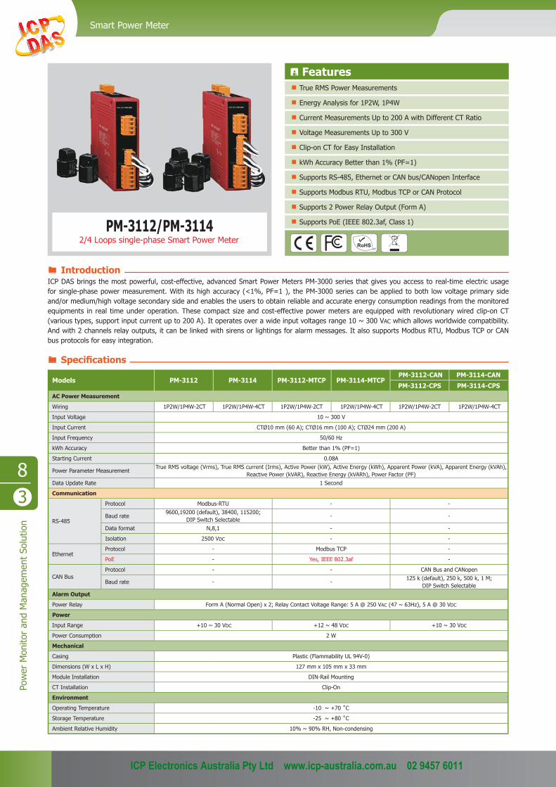
PM-3112/PM-3114
Features True RMS Power Measurements
Energy Analysis for 1P2W, 1P4W
Current Measurements Up to 200 A with Different CT Ratio
Voltage Measurements Up to 300 V
Clip-on CT for Easy Installation
kWh Accuracy Better than 1% (PF=1)
Supports RS-485, Ethernet or CAN bus/CANopen Interface
Supports Modbus RTU, Modbus TCP or CAN Protocol
Supports 2 Power Relay Output (Form A)
Supports PoE (IEEE 802.3af, Class 1)
Introduction
Specifi cations
Models PM-3112 PM-3114 PM-3112-MTCP PM-3114-MTCP PM-3112-CAN PM-3114-CAN
PM-3112-CPS PM-3114-CPSAC Power Measurement
Wiring 1P2W/1P4W-2CT 1P2W/1P4W-4CT 1P2W/1P4W-2CT 1P2W/1P4W-4CT 1P2W/1P4W-2CT 1P2W/1P4W-4CT
Input Voltage 10 ~ 300 V
Input Current CTØ10 mm (60 A); CTØ16 mm (100 A); CTØ24 mm (200 A)
Input Frequency 50/60 Hz
kWh Accuracy Better than 1% (PF=1)
Starting Current 0.08A
Power Parameter MeasurementTrue RMS voltage (Vrms), True RMS current (Irms), Active Power (kW), Active Energy (kWh), Apparent Power (kVA), Apparent Energy (kVAh),
Reactive Power (kVAR), Reactive Energy (kVARh), Power Factor (PF) Data Update Rate 1 Second
Communication
RS-485
Protocol Modbus-RTU - -
Baud rate9600,19200 (default), 38400, 115200;
DIP Switch Selectable- -
Data format N,8,1 - -
Isolation 2500 VDC - -
EthernetProtocol - Modbus TCP -
PoE - Yes, IEEE 802.3af -
CAN BusProtocol - - CAN Bus and CANopen
Baud rate - -125 k (default), 250 k, 500 k, 1 M;
DIP Switch SelectableAlarm Output
Power Relay Form A (Normal Open) x 2; Relay Contact Voltage Range: 5 A @ 250 VAC (47 ~ 63Hz), 5 A @ 30 VDC
Power
Input Range +10 ~ 30 VDC +12 ~ 48 VDC +10 ~ 30 VDC
Power Consumption 2 W
Mechanical
Casing Plastic (Flammability UL 94V-0)
Dimensions (W x L x H) 127 mm x 105 mm x 33 mm
Module Installation DIN-Rail Mounting
CT Installation Clip-On
Environment
Operating Temperature -10 ~ +70 ˚C
Storage Temperature -25 ~ +80 ˚C
Ambient Relative Humidity 10% ~ 90% RH, Non-condensing
ICP DAS brings the most powerful, cost-effective, advanced Smart Power Meters PM-3000 series that gives you access to real-time electric usage for single-phase power measurement. With its high accuracy (<1%, PF=1 ), the PM-3000 series can be applied to both low voltage primary side and/or medium/high voltage secondary side and enables the users to obtain reliable and accurate energy consumption readings from the monitored equipments in real time under operation. These compact size and cost-effective power meters are equipped with revolutionary wired clip-on CT (various types, support input current up to 200 A). It operates over a wide input voltages range 10 ~ 300 VAC which allows worldwide compatibility. And with 2 channels relay outputs, it can be linked with sirens or lightings for alarm messages. It also supports Modbus RTU, Modbus TCP or CAN bus protocols for easy integration.
2/4 Loops single-phase Smart Power Meter
ICP Electronics Australia Pty Ltd www.icp-australia.com.au 02 9457 6011

Remote I/O Modules and I/O Expansion Units
83
Power M
onitor and Managem
ent Solution
Appearance
PowerRUN
LED indicators
1P2W-2CT
1P4W-2CT
1P2W-4CT
1P4W-4CT
DO1DO0CT3-K(W)
CT3-L(B)
CT4-K(W)
CT4-L(B)
Bottom View Rear ViewRight Side View Front View Top ViewLeft Side View
Dimensions (Units: mm)
7
33
100
110.0
90.09.8
7.0
110
10
90 35.6
33.0
Selection Guide
PM-311
RS-485 Interface
PM-3112-100 Modbus RTU; 2 loops single-phase Power Meter with 2 CTs (60 A)
PM-3112-160 Modbus RTU; 2 loops single-phase Power Meter with 2 CTs (100 A)
PM-3112-240 Modbus RTU; 2 loops single-phase Power Meter with 2 CTs (200 A)
Ethernet Interface (Available soon)
PM-3112-100-MTCP Modbus TCP; 2 loops single-phase Power Meter with 2 CTs (60 A)
PM-3112-160-MTCP Modbus TCP; 2 loops single-phase Power Meter with 2 CTs (100 A)
PM-3112-240-MTCP Modbus TCP; 2 loops single-phase Power Meter with 2 CTs (200 A)
CAN Bus Interface
PM-3112-100-CAN CAN Bus; 2 loops single-phase Power Meter with 2 CTs (60 A)
PM-3112-160-CAN CAN Bus; 2 loops single-phase Power Meter with 2 CTs (100 A)
PM-3112-240-CAN CAN Bus; 2 loops single-phase Power Meter with 2 CTs (200 A)
CANopen Interface (Available soon)
PM-3112-100-CPS CANopen; 2 loops single-phase Power Meter with 2 CTs (60 A)
PM-3112-160-CPS CANopen; 2 loops single-phase Power Meter with 2 CTs (100 A)
PM-3112-240-CPS CANopen; 2 loops single-phase Power Meter with 2 CTs (200 A)
RS-485 Interface (Available soon)
PM-3114-100 Modbus RTU, 4 loops single-phase power meter (60 A)
PM-3114-160 Modbus RTU, 4 loops single-phase power meter (100 A)
PM-3114-240 Modbus RTU, 4 loops single-phase power meter (200 A)
Ethernet Interface (Available soon)
PM-3114-100-MTCP Modbus TCP, 4 loops single-phase power meter (60 A)
PM-3114-160-MTCP Modbus TCP, 4 loops single-phase power meter (100 A)
PM-3114-240-MTCP Modbus TCP, 4 loops single-phase power meter (200 A)
CAN Bus Interface (Available soon)
PM-3114-100-CAN CAN Bus, 4 loops single-phase power meter (60 A)
PM-3114-160-CAN CAN Bus, 4 loops single-phase power meter (100 A)
PM-3114-240-CAN CAN Bus, 4 loops single-phase power meter (200 A)
CANopen Interface (Available soon)
PM-3114-100-CPS CANOpen, 4 loops single-phase power meter (60 A)
PM-3114-160-CPS CANOpen, 4 loops single-phase power meter (100 A)
PM-3114-240-CPS CANOpen, 4 loops single-phase power meter (200 A)
Ordering Information
Channel2: 2 Loops4: 4 Loops
-xCT size (measurement)100: CTΦ10 mm (0 ~ 60 A)160: CTΦ16 mm (0 ~ 100 A)240: CTΦ24 mm (0 ~ 200 A)
Communication: RS-485
CAN: CAN BusCPS: CANopenMTCP: Modbus TCP
RL0 COM
RL0 NO
DO0
RL1 COM
RL1 NO
DO1
RS-485 Interface
CAN Bus/CANopen Interface
Ethernet Interface
x xx xx x
ICP Electronics Australia Pty Ltd www.icp-australia.com.au 02 9457 6011

83
Pow
er M
onito
r an
d M
anag
emen
t So
lutio
nSmart Power Meter
Installation
Clip-on CT InstallationDIN-Rail Mounting
A B C
Dimensions (Units: mm)
Wiring for 220V with no neutral
Side Front View Back ViewTopViewTT
39
2523
39.0
23.3
14.826.0
22.0 45.549.0
77.0
24.0
34.443.0
47.2
29.032.0
47.0
16.0
10.0
18.031.5
26.0
100: CTΦ10mm (0~60A)
160: CTΦ16mm (0~100A)
240: CTΦ24mm (0~200A)
Vieewewewewewewweweewweeweeweweweeeeeeeeeee
Bottom View
Bottom View
Bottom View
Top View
Top View
Top View
Left View
Left View
Left View
Front View
Front View
Front View
Rear View
Rear View
Rear View
Right View
Right View
Right View
● Introduction ● CT for Smart Power Meter
220V LOAD
L2 220 VAC (50/60 Hz) L1 PM-3112
ICP Electronics Australia Pty Ltd www.icp-australia.com.au 02 9457 6011

Remote I/O Modules and I/O Expansion Units
84
Power M
onitor and Managem
ent Solution
Vout1GNDVout2GNDVout3GND
+VsGNDF.G.
NC
Vin 1 -Vin 1+
Vin 2 -Vin 2+
Vin 3 -Vin 3+
Vin 4 -Vin 4+
Vin 5 -Vin 5+
Vin 6 -Vin 6+
Vin 7 -Vin 7+
Vin 8 -Vin 8+
+VsGNDF.G.
Vin 1 -
Vin 1+
NCVin 2 -
Vin 2+
NCVin 3 -
Vin 3+
Vout1 +OP Amp1
OP Amp2
OP Amp3
OP Amp4
OP Amp5
OP Amp6
OP Amp7
OP Amp8
Vout1 -Vout2 +Vout2 -Vout3 +Vout3 -Vout4 +Vout4 -Vout5 +Vout5 -Vout6 +Vout6 -Vout7 +Vout7 -
Vout8 +Vout8 -
DN-843V-600V DN-848VI-10V/DN-848VI-80V/DN-848VI-150V
8.4. Voltage Attenuator
The DN-800V series are voltage input attenuator. The maximum input range is from ±80 V to ±600 V and can be attenuated to ±10 V. The "I" version provide 3000 VDC intra-modules isolation and 3000 VDC channel to channel isolation to avoid the noise interference from inputs to outputs or channel to channel. It can be used with the analog input modules such as I-7017 and I-87017 etc. to measure the high voltage.
DN-848VI-80V DN-848VI-150V
Features AC/DC Source Input
High Voltage Input Measurement
Linear Attenuation Ratio
High Input Impedance
Channel to Channel Isolation for DN-848VI-10V, DN-848VI-80V and DN-848VI-150V
4 kV ESD Protection
3 kV Surge Protection
RoHS Compliance
Operating Temperature: -25 ~ +75°C
Easily Wire Connection
DN-848VI-10VDN-843V-600V
Applications
Introduction
Appearance
ICP Electronics Australia Pty Ltd www.icp-australia.com.au 02 9457 6011

84
Pow
er M
onito
r an
d M
anag
emen
t So
lutio
nVoltage Attenuator
174
122117.6
41.05
35.45
41.1
3.2
33
174
122117.6
41.05
35.45
41.1
3.2
9 9
24.5
Models DN-848VI-10V DN-848VI-80V DN-848VI-150V DN-843V-600V
General
Channels 8 8 8 3
Input Type AC/DC Voltage
Input Range +/-10 Vpp +/-80 Vpp +/-150 Vpp +/-600 VppOutput Range +/-10 VppAccuracy 1% of FSR
Chanel to Channel Isolation Yes, 3000 VDC -
Bandwidth 30 KHz 100 KHz
Input Impedance > 1 MΩ
Intra-module Isolation, Input to Output 3000 VDC -
EMS Protection
ESD (IEC 61000-4-2) +/-4 kV contact for power line, input and output channels , +/-8 kV air for random point
Surge (IEC 61000-4-5) +/-3 kV for power liner
Power Input
Input Range +10 ~ +30 VDC
Power Consumption 9.2 W 9.2 W 9.2 W 0.56 W
Mechanical
Dimensions (W x L x H) 122 mm x 174 mm x 33 mm 122 mm x 174 mm x 24.5 mm
Installation DIN-Rail Mounting
Environment
Operating Temperature -25 ~ + 75°C
Storage Temperature -30 ~ +75°C
Humidity 10 ~ 90% RH (non-condensing)
DN-848VI-10V CR 8-channel 10 V Voltage Attenuator (RoHS)
DN-848VI-80V CR 8-channel 80 V Voltage Attenuator (RoHS)
DN-848VI-150V CR 8-channel 150 V Voltage Attenuator (RoHS)
DN-843V-600V CR 3-channel 600 V Voltage Attenuator (RoHS)
MDR-20-24 CR24 V/1 A, 24 W Power Supply with DIN-Rail Mounting (RoHS)
I-7017-G CR 8-channel Analog Input Module (RoHS)
I-87017-G CR 8-channel Analog Input Module (RoHS)
DN-84 - x xx x x xNumber of Channels3: 3 channels8: 8 channels
V: Voltage I: Channel to channel Isolation Input Voltage Range
Bottom ViewTop View Bottom ViewTop View
Left View Front View Rear ViewRight View Left View Front View Rear ViewRight View
DN-843V-600V DN-848VI-10V/DN-848VI-80V/DN-848VI-150V
Specifi cations
Selection Guide
Ordering Information Accessories
Dimensions (Units: mm)
ICP Electronics Australia Pty Ltd www.icp-australia.com.au 02 9457 6011
Remote I/O Modules and I/O Expansion Units
85
Power M
onitor and Managem
ent Solution
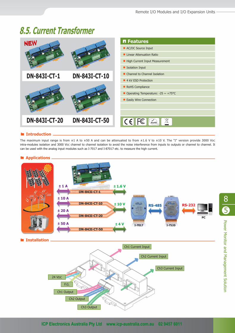
DN-843I-CT-20 DN-843I-CT-50
DN-843I-CT-10DN-843I-CT-1
8.5. Current Transformer
The maximum input range is from ±1 A to ±50 A and can be attenuated to from ±1.6 V to ±10 V. The "I" version provide 3000 VDC
intra-modules isolation and 3000 VDC channel to channel isolation to avoid the noise interference from inputs to outputs or channel to channel. It can be used with the analog input modules such as I-7017 and I-87017 etc. to measure the high current.
Features AC/DC Source Input
Linear Attenuation Ratio
High Current Input Measurement
Isolation Input
Channel to Channel Isolation
4 kV ESD Protection
RoHS Compliance
Operating Temperature: -25 ~ +75°C
Easily Wire Connection
Ch1 Current Input
Ch2 Current Input
Ch3 Current Input
24 VDC
Ch1 Output
Ch2 Output
Ch3 Output
F.G.
Introduction
Applications
Installation
ICP Electronics Australia Pty Ltd www.icp-australia.com.au 02 9457 6011

85
Pow
er M
onito
r an
d M
anag
emen
t So
lutio
nCurrent Transformer
Models DN-843I-CT-1 DN-843I-CT-10 DN-843I-CT-20 DN-843I-CT-50
General
Channels 3
Input Type AC/DC Current
Input Range +/-1 A +/-10 A +/-20 A +/-50 A
Output Type AC/DC Voltage
Output Range +/-1.6 Vpp +/-10 Vpp +/-10 Vpp +/-4 VppCT Type Solid Core (closed)
Accuracy 1% of FSR
Chanel to Channel Isolation Yes, 3000 Vrms
Intra-module Isolation, Input to Output 3000 VDC
Bandwidth 50 KHz
Input Impedance > 1 MΩ
EMS Protection
ESD (IEC 61000-4-2) +/-4 kV contact for power line, input and output channels, +/-8 kV air for random point
Power Input
Input Range +10 ~ +24 VDC
Power Consumption 1.2 W
Mechanical
Dimensions (W x L x H) 148 mm x 83 mm x 39 mm
Installation DIN-Rail Mounting
Environment
Operating Temperature -25 ~ + 75°C
Storage Temperature -30 ~ +75°C
Humidity 10 ~ 90% RH (non-condensing)
DN-843I-CT-1 CR 3-channel 1 A Current Transformer (RoHS)
DN-843I-CT-10 CR 3-channel 10 A Current Transformer (RoHS)
DN-843I-CT-20 CR 3-channel 20 A Current Transformer (RoHS)
DN-843I-CT-50 CR 3-channel 50 A Current Transformer (RoHS)
MDR-20-24 CR24 V/1 A, 24 W Power Supply with DIN-Rail Mounting (RoHS)
I-7017-G CR 8-channel Analog Input Module (RoHS)
I-87017-G CR 8-channel Analog Input Module (RoHS)
DN-84 - -xx x x xI: Channel to channel Isolation CT: Current Transformer Input Current Range
Bottom View
Top View
Left View Front View Right View
8375.7
148.039.0
24.4
Number of Channels3: 3 channels
Specifi cations
Selection Guide
Dimensions (Units: mm)
Ordering Information Accessories
ICP Electronics Australia Pty Ltd www.icp-australia.com.au 02 9457 6011