2012/06/03 north anna 3 col hearing - from gina borsh
TRANSCRIPT
1
PMNorthAnna3COLPEmails Resource
From: [email protected]: Sunday, June 03, 2012 9:11 PMTo: Patel, Chandu; Galvin, DennisCc: [email protected]; [email protected]; [email protected];
[email protected]: From Gina Borsh: Draft Slides for SCP PresentationAttachments: 20120607 S-COLA Seismic Closure Plan Presentation R4.pdf
Chandu and Dennis, Attached are the draft slides for our presentation of the Seismic Closure Plan on Thursday. We'll provide hard copies of the final slides at the meeting, and electronic versions of the final slides later. If you have any feedback that you'd like to provide before our meeting, just let me know. Thanks, Gina

Hearing Identifier: NorthAnna3_Public_EX Email Number: 1085 Mail Envelope Properties (8CF10060A07AB84-8B8-1017E) Subject: From Gina Borsh: Draft Slides for SCP Presentation Sent Date: 6/3/2012 9:11:00 PM Received Date: 6/3/2012 9:11:15 PM From: [email protected] Created By: [email protected] Recipients: "[email protected]" <[email protected]> Tracking Status: None "[email protected]" <[email protected]> Tracking Status: None "[email protected]" <[email protected]> Tracking Status: None "[email protected]" <[email protected]> Tracking Status: None "Patel, Chandu" <[email protected]> Tracking Status: None "Galvin, Dennis" <[email protected]> Tracking Status: None Post Office: webmail-m087.sysops.aol.com Files Size Date & Time MESSAGE 343 6/3/2012 9:11:15 PM 20120607 S-COLA Seismic Closure Plan Presentation R4.pdf 611168 Options Priority: Standard Return Notification: No Reply Requested: No Sensitivity: Normal Expiration Date: Recipients Received:

DRAFT Seismic Closure Plan June 7, 2012
North Anna 3 COLA
DRAFT 06/03/2012

Introduction and Agenda
� Introduction � Purpose � Background � Overview of Seismic Closure Plan
(SCP) Strategy � Details of Significant Changes � RAI Evaluation
DRAFT 06/03/2012

3
Presenters
� Purpose, Background, Overview: G. Borsh
� Mineral, VA Earthquake: D. Fenster � Vibratory Ground Motion: J. Litehiser � Vs Profiles: J. Davie � FIRS: A. Hashemi � Seismic Analyses: L. Todorovski � RAI Evaluation: G. Borsh
DRAFT 06/03/2012

4
Purpose of Meeting
� Provide NRC staff with overview of
planned revisions to S-COLA resulting from SCP work
� Answer NRC questions � Obtain NRC feedback
DRAFT 06/03/2012

5
Background � NRC requested seismic schedules for DCD, R-
COLA, and S-COLA: – March 2012: MHI submitted latest DCD SCP – February 2012: Dominion submitted limited
S-COLA SCP (FSAR 2.5, 2.5.1, 2.5.3) – April 2012: Luminant submitted R-COLA
SCP – May 2012: Dominion submitted
comprehensive S-COLA SCP

6
Background
SCP addresses: � US-APWR DCD seismic changes � New CEUS models � August 23, 2011 earthquake near North
Anna site

7
Overview of SCP Strategy
� Gather geologic information and perform field reconnaissance activities related to August 23, 2011 Mineral, VA earthquake
� Develop revised site-specific hard rock PSHA and GMRS
� Update Vs profiles for small-strain properties to reflect revised Unit 3 layout
� Develop revised FIRS and strain-compatible soil profiles for each seismic Cat I structure and for T/B and E/R
DRAFT 06/03/2012

8
Overview of SCP Strategy (cont)
� Update designs and seismic analyses for: – Reactor Building (R/B) Complex (includes PCCV, R/B,
A/B, and east and west PS/Bs) – UHSRS – PSFSVs – ESWPT
� Perform SSI analyses of T/B and E/R � Update miscellaneous chapters impacted by
seismic changes (e.g., FSAR Ch 8) � Compare key equipment TRs to Unit 3 seismic
results

9
Details: Mineral, VA Earthquake
� M 5.8 Mineral, VA, earthquake on August 23, 2011 in Central Virginia Seismic Zone
� Geologic field reconnaissance in vicinity of site: – Compiled geologic maps – Obtained LiDAR data, derivative maps and photos – Discussions with VGS, USGS and others – Reviewed aftershock seismology data – Performed field study
� No evidence for surface faulting

� Impact on Current COLA – Update information on Quaternary tectonic
features in FSAR Section 2.5.1.1.4 – Add a description of the event in a new FSAR
Subsection 2.5.1.1.6 � Affected FSAR Sections
– Geologic descriptions in Sections 2.5.1 and 2.5.3 – Potential for impact on PSHA in Section 2.5.2
10
Details: Mineral, VA Earthquake (cont)
DRAFT 06/03/2012

11
Overview: FSAR Section 2.5.2, Vibratory Ground Motion
SSAR Section 2.5.2 will be replaced: – Expand ESP VAR 2.0-4 - Vibratory Ground Motion – Use 2012 publication of the CEUS SSC report:
� New seismicity catalog through 2008 � New seismic source characterization [SSC] model
– Post CEUS SSC report information will consider: � Updated seismicity through mid-December 2011 � Updated SSC, if needed: e.g., to incorporate implications of
more recent seismicity (the 2011 Mineral, VA, earthquake) or additional regional or local source information
– Re-run PSHA using the new/updated SSC – Develop GMRS based on RG 1.208 at the common
basemat foundation elevation for the R/B Complex

12
Overview: FSAR Section 2.5.2, Vibratory Ground Motion (cont)
� CEUS SSC, updated seismicity catalog, and Mineral EQ require a complete rewrite of Section 2.5.2 – 2.5.2.1 Seismicity – 2.5.2.2 Geologic and Tectonic Characteristics of the Site and
Region – 2.5.2.3 Correlation of Earthquake Activity with Seismic
Sources – 2.5.2.4 Probabilistic Seismic Hazard Analyses and Controlling
Earthquake – 2.5.2.5 Seismic Wave Transmission Characteristics of the Site – 2.5.2.6 Ground Motion Response Spectrum
13
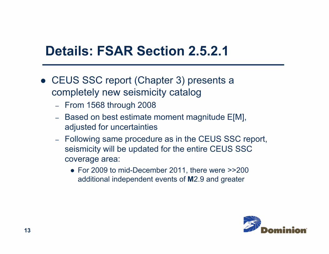
Details: FSAR Section 2.5.2.1
� CEUS SSC report (Chapter 3) presents a completely new seismicity catalog – From 1568 through 2008 – Based on best estimate moment magnitude E[M],
adjusted for uncertainties – Following same procedure as in the CEUS SSC report,
seismicity will be updated for the entire CEUS SSC coverage area: � For 2009 to mid-December 2011, there were >>200
additional independent events of M2.9 and greater

14
Details: FSAR Sections 2.5.2.2, 2.5.2.3
� CEUS SSC report presents a completely new seismic source characterization model – Regional source zones
� Mmax Zones – 3 versions [Wide, Narrow, Study] � Seismotectonic Zones – 4 versions [Wide PEZ/RCGr,
Wide PEZ/RCGm, Narrow PEZ/RCGr, Narrow PEZ/RCGm] – RLME [Repeated Large-Magnitude Earthquakes]
sources
� Review new information and update CEUS SSC, if necessary – Seismicity update [after 2008] – Evaluation of hazard input regarding 2011 Mineral, VA,
earthquake [SSHAC Level 2]

15
Details: FSAR Section 2.5.2.4
� New SSC requires new PSHA – Same median GMPE – EPRI (2004) – Updated GMPE uncertainties – EPRI (2006) – Mmin for PSHA = M5.0, no CAV – Logic tree branches to be trimmed or compressed [see
Chapter 9], analogous to identification of 99%-hazard contribution EPRI-SOG sources

16
Details: FSAR Section 2.5.2.5
� New PSHA requires re-evaluation of the site response [still follows NUREG/CR-6728 App. 2A] – Soil column is the same as for current S-COLA FSAR;
no new soil profile simulation required – Slightly new GMRS horizon elevation may be defined – Explicitly following RG 1.208, site response will be run
using different input rock motions than considered in the current S-COLA: � Current S-COLA: horizontal high-frequency [HF] and low-
frequency [LF] deaggregated hard rock SSE response spectrum used as input to site response
� Planned S-COLA revision: horizontal high-frequency [HF] and low-frequency [LF] deaggregated hard rock 10-4 and 10-5 uniform hazard response spectra (UHRS) used as input to site response

17
Details: FSAR Section 2.5.2.6
� New PSHA and site response analysis requires new GMRS – Site response results in broadband 10-4 and 10-5 UHRS
at the GMRS horizon – Reg. Guide 1.208 performance-based procedure results
in horizontal GMRS – V/H from ESPA SSAR (and S-COLA) is used to develop
vertical GMRS
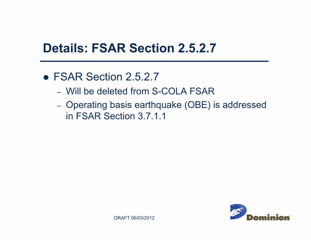
� FSAR Section 2.5.2.7 – Will be deleted from S-COLA FSAR – Operating basis earthquake (OBE) is addressed
in FSAR Section 3.7.1.1
Details: FSAR Section 2.5.2.7
DRAFT 06/03/2012

19
Details: Shear Wave Velocity Profiles � Update current shear wave velocity (Vs) profiles in
FSAR Section 2.5.4 to address: – Revised Unit 3 layout with new configuration of US-APWR
standard plant, and – Redesign of site-specific structures.
� Updates are outlined in the following slides.

Details: Vs Profiles (cont) U
HSR
S C
DU
HSR
S A
B
R/B
PCCV& CIS
East Ps/B
Wes
t Ps/
BA/B
R/B Complex
ESWPT A
tt. T/B
E/R
Turbine Pedestal
UH
S D
UH
S C
UH
S B
UH
S A
ESWPT
ESWPT
East PSFSV
West PSFSV
Segmen
t 1bN
Segment 1bS
Segment 1aN Segment 1bS
Tank
Hou
se
Ac/B

21
Vs Profile of R/B Complex
� Vs profile used for the previous R/B basemat configuration will be used for the enlarged common mat.
� Vs profile will reflect the changed average thickness of concrete fill under the enlarged mat.
21

22
Details: Vs Profile of PSFSVs and T/B
� Vs profiles similar to the previous PSFSV profiles will be used: – Dimensions of each PSFSV in the revised
configuration are similar to the previous design – Appropriate adjustments for concrete fill thickness
� Vs profile for the T/B will be developed: – Use three (3) power block Vs borings, and – Average soil/rock profiles beneath T/B mat. – Profile was not developed previously
22

23
Details: Vs Profiles of UHSRS
� UHSRS A & B will now be placed on a common mat, as will UHSRS C & D
� Vs profile for UHSRS A & B will be similar to the previous profile – Some adjustments to zone thicknesses
� New Vs profile for UHSRS C & D – Based on the Vs borings closest to the common mat, and – Average soil/rock profiles beneath the mat.
� UHSRS Pipe Chase eliminated
23

24
Details: Vs Profiles of ESWPT
� East and West ESWPTs will each be divided into two separate segments
� New Vs profile for each of the 4 segments: – Based on the Vs borings closest to each tunnel
segment, and – Average soil/rock profile beneath each segment.
� Segment 2 of the ESWPT will use the same Vs profile as the R/B complex
24

25
Details: Liquefaction, Slope Stability, Lateral Earth Pressure
� Determine if the peak ground acceleration (pga) increases based on the revised seismic analysis
� Revise analyses for liquefaction (FSAR 2.5.4.8), slope stability (FSAR 2.5.5) and dynamic lateral earth pressure (FSAR 2.5.4.10) if needed: – Factors of safety (FS) against liquefaction and slope failure for
the existing pga are more than adequate – These FS should remain adequate even for an increased pga – Because dynamic lateral earth pressure is proportional to the
pga, a revision in pga will result in an update in dynamic lateral earth pressure
25

26
FSAR Chapter 2 Submittal Dates
� Section 2.0, Site Characteristics: February 2013 – Revise tables and figures to reflect revised DCD
and S-COLA seismic information � Section 2.1, Geography and Demography:
October 2012 – Revise site plan to reflect new plant layout
� Section 2.4, Hydrology: November 2012 – Revise Holdup Tank location and figure
backgrounds
26

27
FSAR Chapter 2 Submittal Dates (cont)
� Sections 2.5, Geology, Seismiology, and Geotechnical Engineering, 2.5.1, Basic Geologic and Seismic Information, and 2.5.3, Surface Faulting: July 2012
� Sections 2.5.2, Vibratory Ground Motion, and Section 2.5.4, Stability of Subsurface Materials and Foundations: January 2013
� Section 2.5.5, Slope Stability: February 2013
27

28
Details: FIRS, SSI Input Soil Profiles, and SSI Input Time-Histories
� Revision of Section 3.7.1 due to: – Updated hard rock motion based on new PSHA results
(Section 2.5.2) – Updated soil and rock profiles and their variation due to
plant layout changes (Section 2.5.4) – Revised licensing basis from RG 1.165 to RG 1.208 – Addition of T/B and E/R to evaluate adequacy of gaps
between Seismic Category II (SC-II) and Seismic Category I (SC-I) structures

29
Details: FIRS, SSI Input Soil Profiles, and SSI Input Time-Histories: Analysis Methodology
� Step-by-step Methodology: – Soil Profile Simulation (No change) – Site Response Analysis (will be updated per RG 1.208) – Horizontal and Vertical FIRS Development (will be updated per
RG 1.208) – SSI Soil Profile Development (will be updated per RG 1.208) – SSI Input Response Spectra Development
� NEI Check (ISG-017), Upward Smoothing (No change) � Minimum Required Spectrum (per 10 CFR 50, App. S) (No change)
– Time History Generation � Outcrop Time-Histories (Matched to SSI Input Response Spectra)
(No change) � In-Column Time-Histories (for SSI Analysis as Embedded) (No
change)
29
30
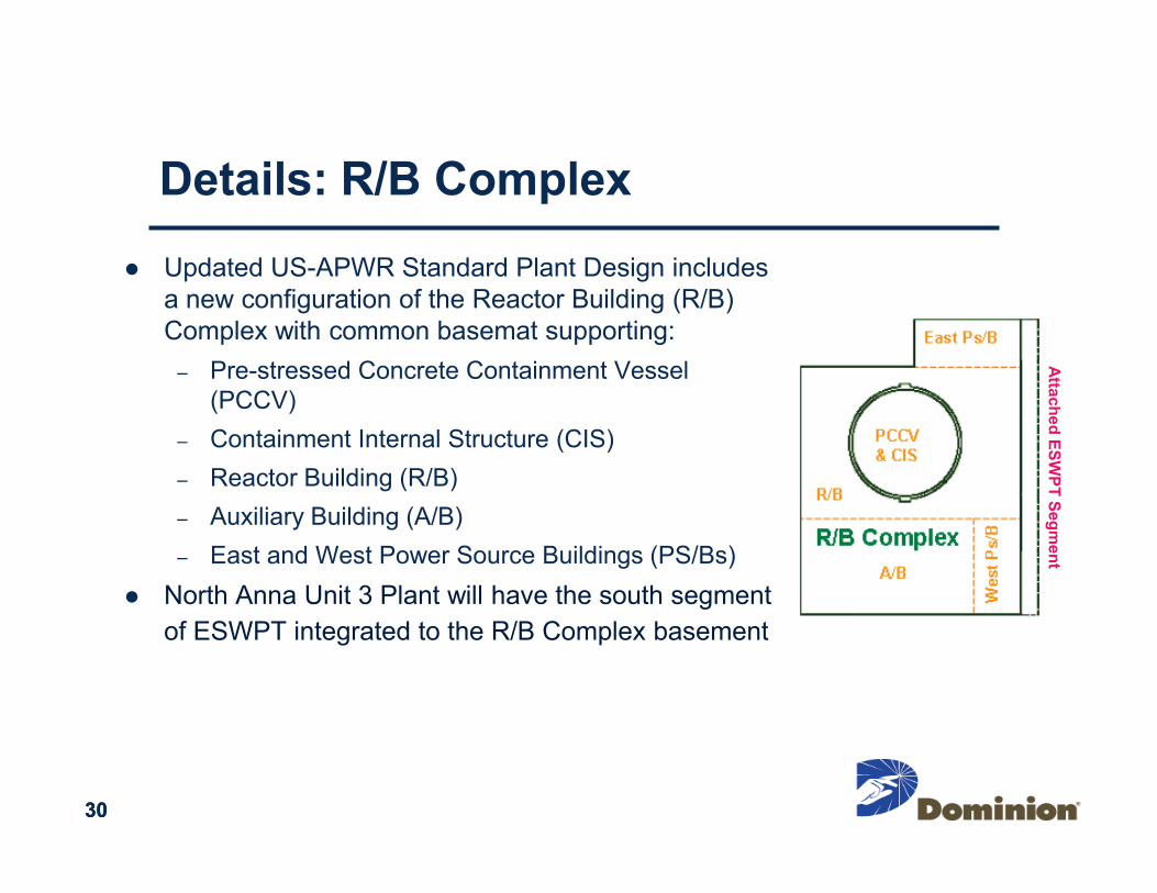
Details: R/B Complex
� Updated US-APWR Standard Plant Design includes a new configuration of the Reactor Building (R/B) Complex with common basemat supporting: – Pre-stressed Concrete Containment Vessel
(PCCV) – Containment Internal Structure (CIS) – Reactor Building (R/B) – Auxiliary Building (A/B) – East and West Power Source Buildings (PS/Bs)
� North Anna Unit 3 Plant will have the south segment of ESWPT integrated to the R/B Complex basement
30
Attached ESW
PT Segment

31
Details: R/B Complex (cont) � Site-specific seismic response analyses of R/B Complex will use the dynamic
finite element model (FEM), documented in MHI Technical Report MUAP-10006(R3), with NA3 site-specific modifications
Updated Standard Plant Design Basis R/B Complex Dynamic FEM
R/B Complex LMSM used for previous revisions of DCD and S-COLA

32
Details: R/B Complex (cont)
(*) Structural models with upper bound full (uncracked concrete) stiffness properties will provide
higher responses due to high frequency content of NA3 site-specific motion (**)
SDOF oscillators are used to capture out-of-plane response of cracked slabs and walls
32
� Structural properties used for NA3 site-specific and standard design SSI analyses of R/B Complex
Structure Structural Properties DCD Standard Design S-COLA (*)
Stiffness Damping ISRS SSE Loads ISRS and SSE Loads
CIS Full (uncracked) 4% X X X
Reduced (cracked) 5% X X
PCCV Full (uncracked) 3% X X X
Reduced (cracked) 5% X X
R/B, A/B, PS/Bs
Full (uncracked) 4% X X (**)
Reduced (cracked) 7% X X

33
Details: R/B Complex (cont)
33
� Types of site-specific soil-structure interaction (SSI) analyses to be performed on NA3 R/B Complex Dynamic FEM
Model
Input Profiles Input Motion
Purpose
Surface Foundation
Truncated Column SLB, SBE, SUB
Coherent Define design ISRS at lower frequencies where incoherency effects are insignificant and envelope responses to incorporates embedment amplifications.
Embedded Foundation
Full Column ELB, EBE, EUB
Coherent
Surface Foundation
Truncated Column SLB, SBE, SUB Incoherent
Define design ISRS at high frequencies where incoherency effects are significant
Embedded Foundation
Full Column EUB Incoherent
Study to demonstrate that surface foundation analyses provide adequate design ISRS
Surface Foundation (*)
Truncated Column SLB, SBE, SUB
Coherent Study to demonstrate that NA3 site-specific and standard design ISRS bound concrete cracking effects
(*) Structural model with reduced (cracked concrete) stiffness properties will be used
34
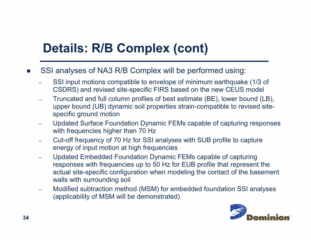
Details: R/B Complex (cont) � SSI analyses of NA3 R/B Complex will be performed using:
– SSI input motions compatible to envelope of minimum earthquake (1/3 of CSDRS) and revised site-specific FIRS based on the new CEUS model
– Truncated and full column profiles of best estimate (BE), lower bound (LB), upper bound (UB) dynamic soil properties strain-compatible to revised site-specific ground motion
– Updated Surface Foundation Dynamic FEMs capable of capturing responses with frequencies higher than 70 Hz
– Cut-off frequency of 70 Hz for SSI analyses with SUB profile to capture energy of input motion at high frequencies
– Updated Embedded Foundation Dynamic FEMs capable of capturing responses with frequencies up to 50 Hz for EUB profile that represent the actual site-specific configuration when modeling the contact of the basement walls with surrounding soil
– Modified subtraction method (MSM) for embedded foundation SSI analyses (applicability of MSM will be demonstrated)

35
Details: R/B Complex (cont)
� Structure-Soil-Structure Interaction (SSSI) effects: – Coherent surface foundation SSI analyses of stand alone R/B Complex
Dynamic FEM will provide field responses at locations of nearby foundations – Field nodes acceleration response spectra will be compared to input ground
motion spectra to assess general importance of SSSI for NA3 site – Responses obtained from coherent surface foundation analyses of combined
model of R/B Complex, T/B, ESWPT, West PSFSV will be used to include SSSI effects into R/B Complex design basis
35

36
Details: R/B Complex (cont)
� Seismic analyses for the R/B Complex will: – Demonstrate the acceptability of the site-specific seismic
design basis by evaluating effects of revised ground motions on structural integrity
– Confirm that standard plant structural design is bounding for North Anna Unit 3
– Provide new site-specific design basis ISRS – Confirm stability and provide new dynamic bearing
pressures
37
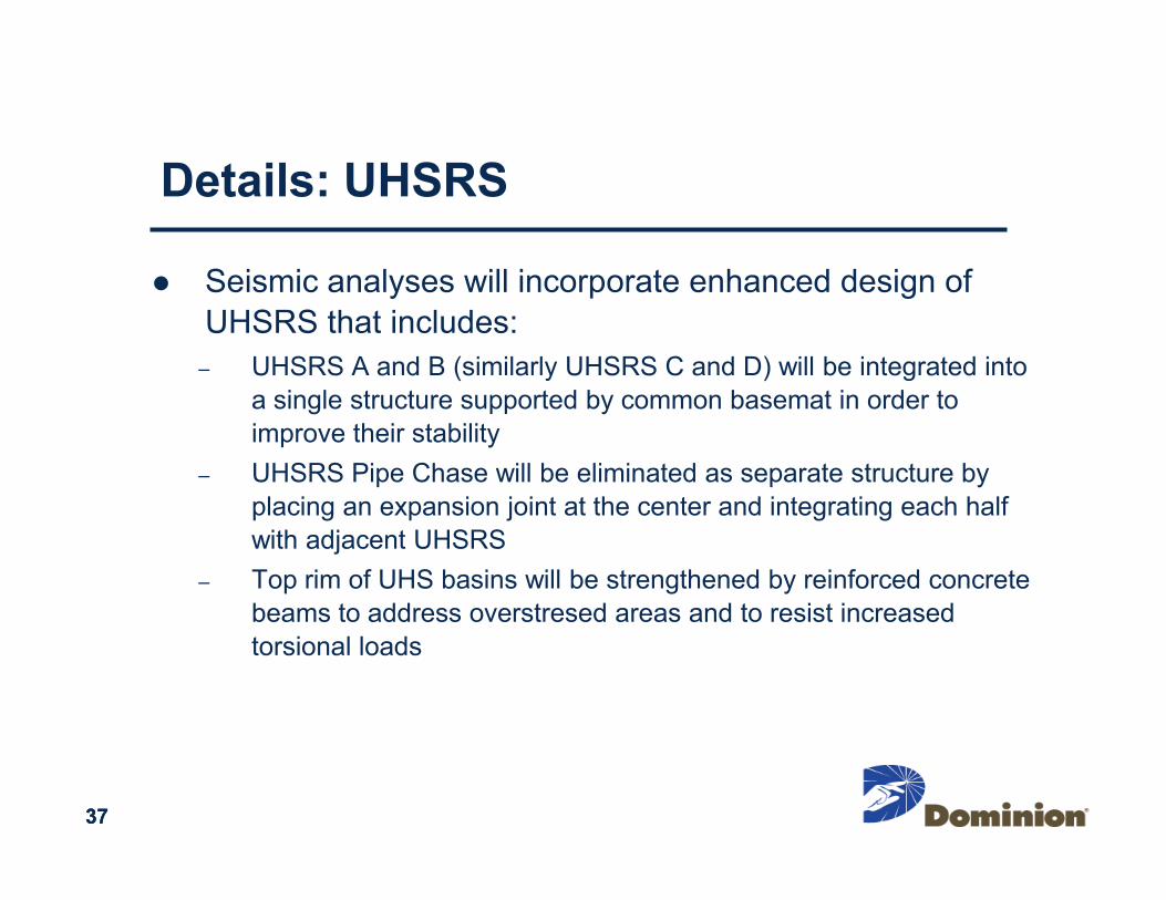
Details: UHSRS
� Seismic analyses will incorporate enhanced design of UHSRS that includes: – UHSRS A and B (similarly UHSRS C and D) will be integrated into
a single structure supported by common basemat in order to improve their stability
– UHSRS Pipe Chase will be eliminated as separate structure by placing an expansion joint at the center and integrating each half with adjacent UHSRS
– Top rim of UHS basins will be strengthened by reinforced concrete beams to address overstresed areas and to resist increased torsional loads
37

38
Details: UHSRS (cont) � Seismic response and static design analyses of UHSRS
will use FEMs that: – Reflect updated configuration and design enhancements – Include field nodes at nearby ESWPT foundations – Use OBE structural damping and full (uncracked concrete) in-plane
stiffness of walls and slabs that provide higher responses for high frequency NA3 site-specific design ground motion
– Use best estimate out-of-plane stiffness of walls and slabs based on concrete cracking stress evaluation
– Consider two bounding loading cases: 1. AB with two basins full of water 2. ABE with basin B being full and basin A empty
– Consider impulsive and sloshing modes of vibration of basin water

39
Details: UHSRS (cont)
39
� Types of SSI analyses to be performed for NA3 UHSRS
Model
Input Profiles Input Motion
Purpose
Surface Foundation
Truncated Column SLBe, SLBw, SBEe, SBEw, SUBe, SUBw
Coherent Develop design basis ISRS and SSE Loads and provide base reaction time histories
Surface Foundation (*)
Truncated Column SLBw Coherent
Include concrete cracking effects into design basis ISRS
Embedded Foundation
Full Column EUBe
Coherent Embedment study to demonstrate that surface foundation analyses provide adequate design basis
Surface Foundation (**)
Truncated Column SBEe
Coherent Basin water fluctuation study to demonstrate that AB and ABE models provide bounding design
(*) AB structural model with reduced (cracked concrete) stiffness properties will be used
(**) Basin water fluctuation study model will consider UHS B full A and UHS A half full

40
Details: UHSRS (cont) � SSI analyses of NA3 UHSRS will be performed using:
– SSI input motions compatible to envelope of minimum earthquake (1/3 of CSDRS) and revised site-specific FIRS based on new CEUS model
– Truncated column profiles of east and west best estimate (Bee and BEw), lower bound (LBe and LBw), upper bound (Ube and UBw) dynamic soil properties strain-compatible to revised site-specific ground motion
– Updated FEMs capable of capturing responses with frequencies at least 70 Hz for SUB and cut-off frequency of 70 Hz to capture energy of input motion at high frequencies
– SSI models without symmetry conditions to capture responses of stand alone UHSRS AB and ABE as well as SSI models with symmetry conditions to capture possible SSSI effects between UHSRS AB and CD
– Embedment study ABE FEM capable of capturing responses with frequencies up to 50 Hz using direct method for modeling embedment
40

41
Details: UHSRS (cont)
� Seismic analyses for the UHSRS will: – Demonstrate the acceptability of the site- specific
seismic design basis by evaluating the effects of the revised UHSRS design and ground motions on the structural integrity of the new combined UHSRS structure
– Provide new site-specific design basis ISRS – Confirm stability and provide new dynamic bearing
pressures

42
Details: PSFSVs � Seismic analyses will incorporate enhanced design of East and
West PSFSV: – Segments of ESWPT that were previously integrated with PSFSV will
be detached and integrated to R/B Complex – Design of critical reinforced concrete members will be enhanced to
address overstress areas
� Seismic response and static design analyses will use revised FEMs that: – Reflect updated configuration and design enhancements – Use OBE structural damping and full (uncracked concrete) in-plane
stiffness of walls and slabs that provide higher responses for high frequency NA3 site-specific design ground motion
– Use best estimate out-of-plane stiffness of walls and slabs based on concrete cracking stress evaluation
42

43
Details: PSFSVs (cont)
43
� Types of SSI analyses to be performed for NA3 PSFSVs
Model
Input Profiles
Input Motion
Purpose
Surface Foundation
Truncated Column SLB, SBEe, SBEw,
SUB
Coherent Develop design basis ISRS and SSE Loads and provide base reaction time histories
Embedded Foundation
Full Column ELB, EBEe, EBEw,
EUB
Coherent
Include embedment effects into design basis ISRS and calculate dynamic earth pressures
Surface Foundation (*)
Truncated Column SLB
Coherent Include concrete cracking effects into design basis ISRS
(*) Structural model with reduced (cracked concrete) stiffness properties will be used

44
Details: PSFSVs (cont) � SSI analyses of NA3 PSFSVs will be performed using:
– SSI input motions compatible to envelope of minimum earthquake (1/3 of CSDRS) and revised site-specific FIRS based on the new CEUS model
– Truncated and full column profiles of lower bound (LB), upper bound (UB) east and west best estimate (BE) dynamic soil properties strain-compatible to revised site-specific ground motion
– Updated surface foundation FEMs capable of capturing responses with frequencies at least 70 Hz for SUB soil and cut-off frequency of 70 Hz to capture energy of input motion at high frequencies
– Updated Embedded Foundation FEMs capable of capturing responses with frequencies up to 50 Hz for EUB profile that represent actual site-specific configuration when modeling contact of basement walls with surrounding soil
– Modified subtraction method (MSM) for embedded foundation SSI analyses (applicability of MSM will be demonstrated)
44

45
Details: PSFSVs (cont)
� Structure-Soil-Structure Interaction (SSSI) effects on PSFSV design basis will be addressed by:
1. Surface Foundation SSSI Analyses of Combined Model of ESWPT, West PSFSV, R/B Complex and T/B
2. Embedded Foundation SSSI Analysis on Combined Model of East PSFSV and T/B
45
2. Embedded Foundation SSSI Analysis
1. Surface Foundation SSSI Analysis

46
Details: PSFSVs (cont)
� Revised seismic analyses and structural evaluations for PSFSVs will: – Demonstrate acceptability of site-specific seismic design
basis by evaluating effects of enhanced PSFSVs design and ground motions on structural integrity
– Provide new site-specific design basis ISRS – Demonstrate stability and provide new dynamic bearing
pressures

47
Details: ESWPT
� SSI structural models will be updated for the redesign of different segments of the ESWPT: – Use Full (uncracked concrete) stiffness and OBE
damping values – Refine mesh of SASSI models of buried ESWPT
segments to be capable of transmitting frequencies up to 50 Hz for upper bound (EUB) soil case
– SSI analyses for the redesigned ESWPT segments will use the revised site-specific FIRS and new SSI input motions which will be updated to reflect the new CEUS model
– ESWPT analyses will also account for SSSI effects

48
Details: ESWPT � Revised FSAR will incorporate the enhanced design of ESWPT
that includes: – The segment of ESWPT located along the south end of R/B Complex
will be integrated to the R/B complex basement – The cross sections of ESWPT segments will be modified to reflect
changes in essential water pipes configuration – The overpass tunnels connecting East PSFSV with East PSB will be
integrated to ESWPT to address changes in R/B Complex standard plant configuration
– The design of critical reinforced concrete members will be enhanced to address overstress areas
48
49
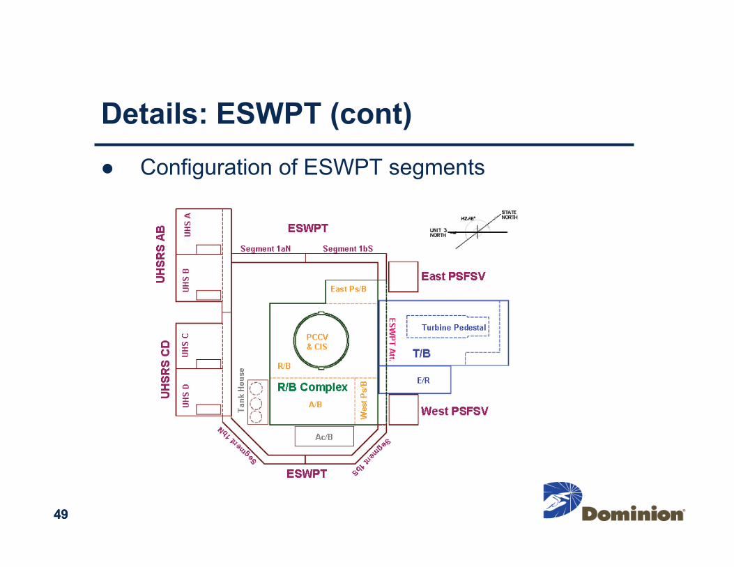
Details: ESWPT (cont) � Configuration of ESWPT segments
49
50
Details: ESWPT (cont) � Seismic response and static design analyses of
ESWPT segments will use revised FEMs that: – Reflect the updated configuration and design enhancements of
Segments 1a and 1b – Use OBE structural damping and two stiffness levels
representing full (uncracked concrete) stiffness and reduced (cracked concrete) stiffness
50

51
Details: ESWPT(cont)
51
� Types of SSI analyses to be performed for NA3 ESWPT
Model
Input Profiles Input Motion
Purpose
Underground straight
segment 1aN
Full Column ELB, EBEe, EUB Coherent
Develop design basis ISRS and SSE Loads
Underground segment 1aS
Full Column ELB, EBEe, EUB Coherent
Underground skewed
segment 1a
Full Column ELB, EBEw, EUB Coherent

52
Details: ESWPT (cont) � SSI analyses of NA3 ESWPT Segments will be performed using:
– SSI input motions compatible to the envelope of minimum earthquake (1/3 of CSDRS) and revised site-specific FIRS based on the new CEUS model
– Full column profiles of lower bound (LB), upper bound (UB) east and west best estimate (BE) dynamic soil properties strain-compatible to revised site-specific ground motion
– Updated Embedded Foundation FEMs capable of capturing responses with frequencies up to 50 Hz for EUB profile that represent the actual site-specific configuration when modeling the contact of the tunnel walls and roof with surrounding soil
– Modified subtraction method (MSM) for modeling SSI embedment (applicability of MSM will be demonstrated)
– Input acceleration time histories compatible to the ground motion design response spectra that are amplified for SSSI effects based on field node responses obtained from SSI analyses of UHSRS
52

53
Details: ESWPT (cont)
� Revised FSAR seismic analyses for the ESWPT segments will: – Demonstrate the acceptability of the site-specific seismic
design basis by evaluating the effects of the revised designs of the ESWPT segments and ground motions on structural integrity
– Provide new site-specific design basis ISRS – Confirm stability and provide new dynamic bearing
pressures

54
Details: T/B and E/R � Purpose of performing the SSI analyses on the T/B
and E/R (seismic Category II structures) is to ensure adequate gaps exist between seismic Category II structures and adjacent seismic Category I structures.
� SSI analysis will provide input for evaluating the stability of these buildings during a safe shutdown earthquake (SSE)
� T/B and E/R will be located on separate basemats (departure from DCD)
� Single set of representative FIRS for T/B and E/R � Impacted S-COLA Section 1.2 - GA

55
Details: T/B and E/R (cont)
� Structural models for the SSI analyses will use: – Stiffness properties: full (uncracked concrete) stiffness
for foundation – Damping properties: OBE values – Site-specific design modifications that reflect departures
from the standard plant design (e.g., foundation elevations, separate foundations
� SSI analyses for the T/B and E/R will use site-specific FIRS and SSI input based on the new CEUS model

FSAR Chapter 3 Revisions and Submittal Schedule � Section 3.5.1.6, Aircraft Hazards: November
2012 – Revise total effective plant areas and accident
probabilities to reflect new plant layout � Section 3.7, Seismic Design: April 2013
– Revise to reflect CEUS methodology, RG 1.208, new plant layout and use of OBE damping values
– Revise to reflect common basemat for PS/Bs, CIS, PCCV, R/B and A/B, T/B SSI analyses, and use of OBE damping values to generate ISRS
DRAFT 06/03/2012

FSAR Chapter 3 Revisions and Submittal Schedule (cont)
� Section 3.7 (cont) – Revise Sections 3.7.6, 3.7.2.3.2 - 3.7.2.3.4,
3.7.2.3.6.1, and 3.7.2.4 to incorporate the DCD by reference
– Revise references to appropriate appendices for COL 3.7(3), 3.7(12) and 3.7(26).
– Add NAPS DEP 10.4(1) from Part 11 and revise to address the departure from the GA and foundation of T/B and E/R from standard plant
– Add and revise discussion, tables and figures for new T/B and PSFSV FIRS
DRAFT 06/03/2012

FSAR Chapter 3 Revisions and Submittal Schedule (cont)
� Section 3.8, Design of Category I Structures: May 2013 – Revise GA of ESWPT, UHSRS and PSFSV to
reflect new plant configuration – Revise discussion to reflect new ESWPT
interfaces and analyses – Sections 3.8.4.4.2, 3.8.5.1.2 and 3.8.5.4.3:
Incorporate the DCD text by reference – Revise to reflect common NI basemat,
sliding/overturning analyses for R/B
DRAFT 06/03/2012

FSAR Chapter 3 Revisions and Submittal Schedule (cont) � Section 3.8 (cont)
– Add sliding/overturning analyses for the T/B revise bearing pressures
� Appendix 3.OO: April 2013 – Revise to reflect the new FIRS for the common
R/B Complex basemat � Appendix 3H: May 2013
– Incorporate the DCD by reference
DRAFT 06/03/2012

FSAR Chapter 3 Revisions and Submittal Schedule (cont)
� Appendix 3KK: May 2013 – Create new appendix to incorporate updated
input ground motion, new model of combined foundations for UHS basins, SSI effects and revised analysis results of UHS
– Reflect use of super-elements for UHSRS use of only SSI analyses and to assume full stiffness and OBE damping
DRAFT 06/03/2012

FSAR Chapter 3 Revisions and Submittal Schedule (cont)
� Appendix 3LL: May 2013 – Revise to incorporate updated input ground
motion, analysis results, methodology and SSI effects for ESWPT and reflect new plant arrangement
– Update concrete minimum compressive strength � Appendix 3MM: May 2013
– Add new appendix to incorporate the updated input ground motion, analysis results and new plant arrangement for PSFSV
DRAFT 06/03/2012

FSAR Chapter 3 Revisions and Submittal Schedule (cont) � Appendix 3MM (cont.)
– Revise analysis to reflect use of super-elements for PSFSV, to be based only on SSI analyses, and to assume full stiffness and OBE damping
– Revise PSFSV roof thickness and concrete minimum compressive strength
� Appendix 3NN – Revise to reflect common R/B Complex,
interfaces with ESWPT, use full shear stiffness values for analysis of R/B Complex using OBE damping.
DRAFT 06/03/2012

FSAR Chapter 3 Revisions and Submittal Schedule (cont) � Appendix 3NN (cont)
– App 3NN.2: Revise based on properties from App 3OO and to reflect updated R/B Complex configuration
– App 3NN.3.2: Incorporate the DCD by reference
DRAFT 06/03/2012

64
Details: Other COLA Parts and FSAR Chapters
� FSAR Chapter 1, Introduction: – Sect 1.2 : Plot plan changes due to new plant
layout and associated site specific changes – Sect 1.8 : Update of Departures – Sect 1.9: Add exception to RG 1.132 for
borings and revise conformance evaluations for 1.208 and RG 1.65
– Submittal Date: May 2013

Details: Other COLA Parts and FSAR Chapters � FSAR Section 6.4, Habitability Systems:
– Revise Table 6.4-201 (MCR Toxic Gas Concentrations) to reflect changes in MCR Habitability analysis due to T/B moving south
– Submittal Date: October 2012
� FSAR Chapter 8, Electric Power: – Revise Figure 8.2.-202 (Switchyard Arrangement) to reflect
new standard plant layout and site specific changes – Revise ground grid and lightning protection systems in
Section 8.3 to reflect new standard plant layout and site specific changes
– Submittal Date: December 2012
DRAFT 06/03/2012

Details: Other COLA Parts and FSAR Chapters � FSAR Chapter 9, Auxiliary Systems:
– Section 9.2.5: � Revise Figure 9.2.5-1R (UHS Flow Diagram) and text to reflect
to eliminate the UHSRS Pipe Chase
– Section 9.4: � Revise cooling and heating loads to reflect changes due to
building size and equipment layout
– Section 9.5: � Revise Figure 9.5-201, 9.5-204, 9A-13R, -14R, -20R and-27R
(Fire zones and Arrangements) to reflect new plant layout � Update Fire Hazard Analysis Summary and Fire Zone/Fire
Area interfaces
– Submittal Date: November 2012
DRAFT 06/03/2012
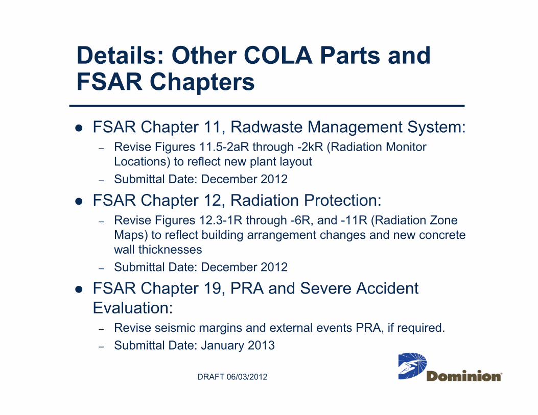
Details: Other COLA Parts and FSAR Chapters � FSAR Chapter 11, Radwaste Management System:
– Revise Figures 11.5-2aR through -2kR (Radiation Monitor Locations) to reflect new plant layout
– Submittal Date: December 2012
� FSAR Chapter 12, Radiation Protection: – Revise Figures 12.3-1R through -6R, and -11R (Radiation Zone
Maps) to reflect building arrangement changes and new concrete wall thicknesses
– Submittal Date: December 2012
� FSAR Chapter 19, PRA and Severe Accident Evaluation: – Revise seismic margins and external events PRA, if required. – Submittal Date: January 2013
DRAFT 06/03/2012

Details: Other COLA Parts and FSAR Chapters � COLA Part 7, Departures
– NAPS DEP 3.7(1): Delete section of departure associated with PS/B basemat design and update descriptions relating to interfaces with ESWPT
– Delete NAPS DEP 3.7(2), 3.7(4), 3.7(5) – NAPS DEP 3.7(6): Add NAPS DEP 3.7(6) to describe
differences in seismic methodologies – NAPS DEP 10.4(1): Revise to reflect departure from GA of
T/B – NAPS ESP VAR 2.0-4: Revise variance to reflect new
common R/B Complex basemat – Submittal date: May 2013
DRAFT 06/03/2012

Details: Other COLA Parts and FSAR Chapters � SCOLA Part 8, Security:
– Revise to reflect new plant layout – Submittal Date :PSP, LOLA: November 2012 – Submittal Date: Supplements to HAE and Physical Security Element
Review: January 2013 – Submittal Date: PSPSR: February 2013
� SCOLA Part 10, Tier 1/ITAAC: – Revise figures to reflect new plant layout and update concrete wall
thicknesses – Submittal Date: December 2012
� SCOLA Part 11 – Delete Part 11 – Submittal Date: May 2013
DRAFT 06/03/2012

RAI Evaluations
� Review submitted RAI responses to identify effects of seismic changes
� Review outstanding RAIs to identify effects of seismic changes
� Provide results of review and response schedule by September 30, 2012
DRAFT 06/03/2012

Questions?