2012 · outback power’s legendary off-grid performance and reliability are the platform for ......
TRANSCRIPT

2012P R O D U C T G U I D E
2012P R O D U C T G U I D E

OutBack Power Technologies is the leading designer and manufacturer of
advanced power components for renewable energy, back-up power, and mobile applications. Based in
Washington State, USA, OutBack creates, designs and engineers the industry’s most advanced power
conversion components. As a member of The Alpha Group, a global alliance of independent companies,
OutBack shares a common philosophy: create best-in-class powering solutions for communications,
commercial, industrial and renewable energy applications. This alliance also provides access to
world class ISO certified manufacturing facilities which enables OutBack to produce innovative,
state-of-the-art, and cost effective products.
Leading renewable energy system designers can afford to be picky. There are three reasons why so
many of them rely on OutBack Power for their clients’ mission-critical needs: OutBack’s industry-leading
reliability and quality standards, technology leadership, and legendary support. That’s why from Baja to
Bangladesh, from the Equator to the poles, you’ll find OutBack components transforming energy from
renewable and conventional sources into the clean, reliable power people need to transform the quality
of their lives. OutBack systems power hospitals, schools, homes, businesses, and all types of installations
on every continent. OutBack products deliver dependable power on Arctic fishing boats, military bases,
research stations, and remote communications installations all over the globe—and even off of it, with
OutBack products traveling on space missions.
Proven reliability in these and countless other applications is how OutBack Power earned the title
“masters of the off-grid™,” and why OutBack components are now the first choice for the new grid.
2

Masters of the Off-Grid™The team at OutBack Power has decades of pioneering experience perfecting power conversion
technologies. OutBack was started to develop a breakthrough in power-conversion technology: a pure
sine-wave inverter in modular form, one capable of producing cleaner, more reliable electricity than
that available even from typical electrical grids—and adaptable to nearly any system configuration
through building-block design.
OutBack’s first innovation meant that an off-grid or grid-interactive system could now meet and even
exceed the rapidly-evolving electrical quality needs of business and residential IT, entertainment and
automation networks and systems, as well as lighting and appliances. With the pure sine-wave inverter,
renewable and back-up energy systems finally had the quality and stability needed to tackle any
mainstream residential or commercial need.
After its revolution in inverter design OutBack turned its attention to charge controllers—those devices
with the dual role of optimizing the output from PV arrays while also maintaining the long-term health
of costly battery banks. OutBack perfected Maximum Power Point Tracking (MPPT) technology which
enables a charge controller to increase the yield from a solar photovoltaic (PV) array as much as 30%
over conventional types. At the industry’s first multi-voltage MPPT controller, OutBack’s FLEXmax
series remains the de facto industry standard charge controller on the market today.
3

First choice for the new gridOutBack Power’s legendary off-grid performance and reliability are the platform for grid-connected
systems for users with higher expectations and demands of their energy investment. Because
battery-back up and advanced digital switching technology is part of the
“brand DNA,” OutBack excels at power-conversion products designed for
the emerging Grid/Hybrid™ category—systems that can provide both
grid-tied economies during normal times, and off-grid independence
when the grid’s down during outages and emergencies.
Grid/Hybrid technology is the key for getting the maximum value and utility out of any energy
system, especially renewable ones. In a PV/solar power system, for example, Grid/Hybrid power-
conversion and back-up components take the PV panel and installation investment beyond the
simple utility savings models such-as net-metering. Unlike a grid-tied one, a Grid/Hybrid system
also provides continuous power when the grid’s down as well as during the evening when the sun
sets. As utility and government incentives change, a Grid/Hybrid system will continue to take full
advantage of offset savings by making it possible to shift on-site generation and storage around
for maximum value to the user.
GRIDHybrid™
4

OutBack’s new Radian series of Grid/Hybrid inverters with FLEXgrid™ technology
demonstrates leadership and commitment in developing and building smarter,
more agile products capable of meeting the demands of next-generation
renewable and back-up energy systems.
Whether a solar panel array, wind-turbine, hydro plant, or a generator, an energy source is just
that: the first step in a complete energy solution. It is the rest of the package— the “balance-
of-system” components— that do the work in managing and delivering power. OutBack Power
is an expert in balance-of-system technology, precision-engineering and manufacturing over
200 components in that category. This dedication to advanced technology, quality and reli-
ability provide system architects and installers with the best component foundation on which
to build the comprehensive, sustainable solutions they need for any renewable and generated
energy application.
5

TABLE OF CONTENTS
Radian Series . . . . . . . . . . . . . . . . . . . . . . . . . . . . . . . . . . . . . . . . . . . . . . . . . . . . . . . . . . . . . . . . . . . . . . . . . . . . 8
Energy Storage . . . . . . . . . . . . . . . . . . . . . . . . . . . . . . . . . . . . . . . . . . . . . . . . . . . . . . . . . . . . . . . . . . . . . . . . . . 12
FLEXpower pre-wired power conversion systems . . . . . . . . . . . . . . . . . . . . . . . . . . . . . . . . . . . . . . . . . 14
Inverter/Chargers . . . . . . . . . . . . . . . . . . . . . . . . . . . . . . . . . . . . . . . . . . . . . . . . . . . . . . . . . . . . . . . . . . . . . . . 16
Off-Grid 60Hz / 120V . . . . . . . . . . . . . . . . . . . . . . . . . . . . . . . . . . . . . . . . . . . . . . . . . . . . . . . . . . . . . . . . 18
Off-Grid 60Hz / 230V . . . . . . . . . . . . . . . . . . . . . . . . . . . . . . . . . . . . . . . . . . . . . . . . . . . . . . . . . . . . . . . . 19
Off-Grid 50Hz / 100V . . . . . . . . . . . . . . . . . . . . . . . . . . . . . . . . . . . . . . . . . . . . . . . . . . . . . . . . . . . . . . . . 20
Off-Grid 50Hz / 120V . . . . . . . . . . . . . . . . . . . . . . . . . . . . . . . . . . . . . . . . . . . . . . . . . . . . . . . . . . . . . . . . 21
Off-Grid 50Hz / 230V . . . . . . . . . . . . . . . . . . . . . . . . . . . . . . . . . . . . . . . . . . . . . . . . . . . . . . . . . . . . . . . . 22
Grid-Interactive 60 Hz / 120V . . . . . . . . . . . . . . . . . . . . . . . . . . . . . . . . . . . . . . . . . . . . . . . . . . . . . . . . . 24
Grid-Interactive . . . . . . . . . . . . . . . . . . . . . . . . . . . . . . . . . . . . . . . . . . . . . . . . . . . . . . . . . . . . . . . . . . . . . 22
Special Application Models
M-Series mobile . . . . . . . . . . . . . . . . . . . . . . . . . . . . . . . . . . . . . . . . . . . . . . . . . . . . . . . . . . . . . . . . . . 26
Extreme series . . . . . . . . . . . . . . . . . . . . . . . . . . . . . . . . . . . . . . . . . . . . . . . . . . . . . . . . . . . . . . . . . . . 29
Limited Power International series . . . . . . . . . . . . . . . . . . . . . . . . . . . . . . . . . . . . . . . . . . . . . . . . 32
FLEXmax Charge Controllers
FM 60 and FM 80 . . . . . . . . . . . . . . . . . . . . . . . . . . . . . . . . . . . . . . . . . . . . . . . . . . . . . . . . . . . . . . . . . . . . 34
6

AXS Port Modbus Interface . . . . . . . . . . . . . . . . . . . . . . . . . . . . . . . . . . . . . . . . . . . . . . . . . . . . . . . . . . . . . . 36
System Communications
MATE3 Controller . . . . . . . . . . . . . . . . . . . . . . . . . . . . . . . . . . . . . . . . . . . . . . . . . . . . . . . . . . . . . . . . . . . . 37
MATE/MATE2 Controllers . . . . . . . . . . . . . . . . . . . . . . . . . . . . . . . . . . . . . . . . . . . . . . . . . . . . . . . . . . . . 38
HUB4/10 Communications Management devices . . . . . . . . . . . . . . . . . . . . . . . . . . . . . . . . . . . . . 39
FLEXnet DC System Monitor . . . . . . . . . . . . . . . . . . . . . . . . . . . . . . . . . . . . . . . . . . . . . . . . . . . . . . . . . 40
FLEXware Integration Enclosures and Hardware
FLEXware 250 Enclosure . . . . . . . . . . . . . . . . . . . . . . . . . . . . . . . . . . . . . . . . . . . . . . . . . . . . . . . . . . . . . 41
FLEXware 500 Enclosure . . . . . . . . . . . . . . . . . . . . . . . . . . . . . . . . . . . . . . . . . . . . . . . . . . . . . . . . . . . . . 43
FLEXware 1000 Enclosure . . . . . . . . . . . . . . . . . . . . . . . . . . . . . . . . . . . . . . . . . . . . . . . . . . . . . . . . . . . . 46
FLEXware Mounting Plate . . . . . . . . . . . . . . . . . . . . . . . . . . . . . . . . . . . . . . . . . . . . . . . . . . . . . . . . . . . 49
PV Combiner Boxes . . . . . . . . . . . . . . . . . . . . . . . . . . . . . . . . . . . . . . . . . . . . . . . . . . . . . . . . . . . . . . . . . 50
FLEXware Transient Surge Protectors . . . . . . . . . . . . . . . . . . . . . . . . . . . . . . . . . . . . . . . . . . . . . . . . 51
Auto Transformers . . . . . . . . . . . . . . . . . . . . . . . . . . . . . . . . . . . . . . . . . . . . . . . . . . . . . . . . . . . . . . . . . . . . . . . 52
System Components and Accessories . . . . . . . . . . . . . . . . . . . . . . . . . . . . . . . . . . . . . . . . . . . . . . . . . . . . . 53
System Stacking Configuration Examples . . . . . . . . . . . . . . . . . . . . . . . . . . . . . . . . . . . . . . . . . . . . . . . . . 58
7

Inverter/ChargersRadian™ Series
TM
GRIDHybrid™
8
Radian Series Inverter/ChargerThe new Radian series GS8048 and GS7048E of Grid/Hybrid™ (full-flexibility grid-interactive/off-grid) inverter/chargers are engineered toward one goal: making system design and installation easier and faster in grid-interactive and comprehensive off-grid applications. Based on OutBack’s proven technology foundation, the Radian series simplifies the configuration, distribution, and implementation of energy storage through a standardized approach when integrated with an OutBack GS Load center, making it easier than ever to provide successful solutions for virtually any residential, commercial or institutional power requirement.
The 120/240V 60Hz split-phase Radian is an 8,000 Watt power solution that seamlessly integrates with traditional North American wiring practices. The all-new 230V 50Hz Radian reflects OutBack’s on-going commitment to clean, reliable power for homes, businesses and other facilities around the world, delivering 7,000 Watts.
Both models combine pure sine-wave power output technology with unsurpassed surge capability to start the most demanding appli-ances, and are built around a unique dual-power module design which ensures high efficiency in both low and full power operation as well as redundancy in mission-critical applications. Both Grid/Hybrid inverters incorporate OutBack’s FLEXgrid™ technology for full operational flexibility. In regions where the ability to sell energy back to the grid may be restricted or limited, the Radian’s offset function means a user can prioritize and still take full advantage of their PV or other renewable energy source and use excess energy to power their loads, “offset-ting” dependence on the grid. In areas where the grid is inconsistent or unreliable, the Radians can seamlessly switch between grid-tied and off-grid operation. The Radians have Dual AC Inputs which automatically switch between an active grid and generator input without the need for an external, costly transfer switch.
The Radian series’ modular system architecture and simplified parallel design supports system scaling of up to ten inverters delivering 80kW (GS8048). The 50Hz GS7048E can support three-phase systems up to 21kW and multiple inverter arrays of up to 70kW.
System integration and programming is easy with OutBack’s powerful MATE3 Control and HUB Communications Management devices. Advanced front-vented layout provides optimum cooling in zero-clearance installations (where units are stacked next to each other, for ex-ample). Field-serviceable design simplifies maintenance if needed, and firmware updates can be easily made in the field without specialized equipment.
Radian Series GS Load CenterThe GSLC is a balance-of-systems enclosure designed to seamlessly integrate with the Radian Series inverter/chargers, FLEXmax Charge Controllers, and OutBack HUB Communications Manager. Three available models allow quick and easy installation of power systems of any size. Additional features of the GSLC line include its powder-coated galvanized chassis, ample knockout locations fitting 1/2” to 2” conduit, aesthetic stainless steel door and simple mounting to a Radian Series inverter/charger. It is listed to UL1741 and CSA C22.2 No. 107.1-01, is Type 1 indoor rated (IP30) and can also be used on its own as a separate breaker enclosure for use with other inverter models.
Bottom• (2) 1/2” knockout (0.875” diameter)• (2) 3/4” knockout (1.109” diameter)• (2) 1” knockout (1.375” diameter)• (2) 1-1/4” knockout (1.734” diameter)• (1) 1-1/2” knockout (1.984” diameter)• (2) 2” knockout (2.468” diameter)
Top (Not used with Radian Series inverter/chargers)• (2) 1” knockout (1.375” diameter)• (2) 2” knockout (2.468” diameter)
Knockout Location Diagram Left Side
• (1) 1/2” knockout (0.875” diameter) • (7) 1” knockout (1.375” diameter) • (2) 2” knockout (2.468” diameter)
Back • (1) 2” knockout (2.468” diameter)
Right Side • (1) 1/2” knockout (0.875” diameter) • (4) 1” knockout (1.375” diameter) • (2) 2” knockout (2.468” diameter)

Inverter/ChargersRadian™ Series
9
Breaker Configuration Diagram Holds up to eighteen 0.75” (19 mm) wide breakers, two 1.5” (39 mm) wide breakers and one FLEXnet DC. Support for optional AC Input-Output-Bypass Assembly. AC breakers are rated from 10-60 amps of AC current. New double-pole 50 amp breaker is available to support 120/240V input and loads.
• Specifications subject to change without notice.
Radian Series Specifications
GS8048 GS7048E (preliminary)**
Nominal DC Input Voltage 48VDC 48VDC
Continuous Output Power at 25°C 8000VA 7000VA
AC Output Voltage / Frequency 120/240VAC / 60Hz 230VAC / 50Hz
Continuous AC Output Current at 25°C 33.3 amps AC at 240VAC 30 amps AC at 230VAC
Idle Consumption - Invert mode, no load 30W 30W
Typical Efficiency 93% 93%
CEC Weighted Efficiency 90% N/A
Total Harmonic Distortion
Maximum total harmonic <5% <5%
Maximum single voltage harmonic <2% <2%
Output Voltage Regulation ± 2% ± 2%
Maximum Output Current 1 ms peak 100 amps AC at 240VAC, 200 amps AC at 120VAC 100 amps AC at 230VAC
100 ms RMS 70.7 amps AC at 240VAC 70.7 amps AC at 230VAC
Overload Capability 100 ms surge 16.97kVA 16.26kVA
5 seconds 12kVA 11.49kVA
30 minute 9kVA 7.88kVA
AC Input Voltage Range (Adjustable) (L1 or L2) 70 to 140VAC 140 to 280VAC
AC Input Frequency Range 54 to 66Hz 45 to 55Hz
Grid-Interactive Voltage Range (L1 or L2) 108 to 132VAC (IEEE) 195.5 to 264.5VAC (EN50438)
Grid-Interactive Frequency Range (L1 or L2) 59.3 to 60.5Hz (IEEE) 47Hz to 51Hz (EN50438)
Maximum AC Input Current 50 amps AC at 240VAC 50 amps AC
Continuous Battery Charge Output 115 amps DC 100 amps DC
DC Input Voltage Range 40 to 64VDC 40 to 64VDC
Temperature Range Rated 0°C to 50°C (power derated above 25°C) 0°C to 50°C (power derated above 25°C)
Maximum* -25°C to 60°C -25°C to 60°C
Accessory Ports Remote Temperature Sensor and MATE3/HUB Communications
Non-volatile Memory Yes Yes
Field Upgradable Firmware Yes Yes
Chassis Type Vented Vented
Certifications ETL Listed to UL1741, CSA C22.2 No. 107.1 CE, IEC 62109, IEC 62093, AS4777, RoHS
Warranty Standard 5 year Standard 5 year
Weight Unit 125 lbs (56.7 kg) 125 lbs (56.7 kg)
Shipping 140 lbs (63.5 kg) 140 lbs (63.5 kg) Dimensions H x W x D Unit 28 x 16 x 8.7” (71.1 x 40.6 x 22.1 cm) 28 x 16 x 8.7” (71.1 x 40.6 x 22.1 cm)
Shipping 14.5 x 34.5 x 21” (36.8 x 87.6 x 53.3 cm) 14.5 x 34.5 x 21” (36.8 x 87.6 x 53.3 cm)
* Functions, but does not necessarily meet all component specifications.
**GS7048E available Q3 2012
GS Load Centers Model: GSLC**odel: GSLC*Description: AC and DC enclosure for use with the Radian Series Inverter/Charger. Recommended for custom-built systems, and for multipleRadian inverter systems (one GSLC per inverter). Includes: Ground bus bar, 500 amp DC shunt assembly, neutral bus bar, two PV (positive) bus bars, inverter power bus bars, FW-BBUS and enclosure mounting hardware.
Unit Weight = 26 lbs (11.8 kg) Shipping Weight = 34 lbs (15.4 kg)Model: GSLC 175-120/240*Description: GS Load Center factory prepared for AC Applications, with inverter DC overcurrent protection and disconnect, dual AC inputs, and 120/240 Vac maintenance bypass assembly. Recommended for systems which have a single Radian inverter and an AC source, but can be customized in other ways.Includes: Ground bus bar, 500 amp DC shunt assembly, neutral bus bar, two PV (positive) bus bars, inverter power bus bars, FW-BBUS, two 175A panel mount breakers, four 50A 120/240VAC double pole panel mount breakers, sliding bypass interlock, AC wiring, and enclosure mounting hardware. Unit Weight = 37 lbs (16.8 kg) Shipping Weight = 45 lbs (20.4 kg)
Model: GSLC 175-PV-120/240*Description: GS Load Center factory prepared for PV and AC Applications, with inverter DC overcurrent protection and disconnect, dual AC inputs, 120/240 VAC maintenance bypass assembly, PV GFDI, and two PV array inputs, FLEXnet DC battery monitor and three shunts. “Plug and play” for systems which have a single Radian inverter and two charge controllers and need battery monitoring.Includes: Ground bus-bar, three 500 amp DC shunts and shunt bus-bar, neutral bus-bar, two PV (positive) bus-bars, inverter power bus-bars, FW-BBUS, two 175A panel mount breakers, four 50A 120/240VAC double-pole panel mount breakers, sliding bypass interlock, two 80A array disconnects, dual pole GFDI and controller disconnects, FLEXnet DC, AC and DC wiring and enclosure mounting hardware.
Unit Weight = 38 lbs (17.2 kg) Shipping Weight = 47 lbs (21.3 kg)
*For all GSLC models: the Unit Dimensions (HxWxD) are 17” x 16” x 8.5” (43.2cm x 40.6cm x 12.6cm) and the Shipping Dimensions (HxWxL) are 23.25” x 20.5” x 13.25” (59.1cm x 52.1cm x 33.7cm).
10
Radian GSLC Sample Bill of Materials
Example of system with single Radian inverter/charger and dual FLEXmax Charge Controllers Part # Description Qty
GS8048 Inverter/Charger 8000W 120/240VAC Grid-Interactive and Standalone solution with dual AC inputs 1
GSLC175-PV-120/240 Prewired GSLC with 175A inverter disconnects, GFDI and PV disconnects for two charge
controllers, FLEXnet DC with 3 shunts, 120/240VAC inverter bypass and dual AC inputs 1
FLEXmax FM80-150VDC 80A output @ 40oC, 12 to 60VDC battery, 150VDC PV maximum 2
MATE3 Universal version, light gray square housing with Ethernet port 1
HUB4 Four Port, up to 4 devices and one MATE 1
FW-MB3 Bracket for mounting a MATE3 System Display on the side of Radian,
GSLC, FW500 and FW1000 DC enclosures 1
FW-CCB2 Mounting bracket for two side mounted charge controllers on GSLC,
FW500 and FW1000 DC enclosures 1
Example of system with dual Radian inverter/charger for UPS or AC only applications
Part # Description Qty
GS8048 Inverter/Charger 8000W 120/240VAC Grid-Interactive and Standalone Solution with dual AC inputs 2
GSLC GS Load Center for Radian Series. Includes inverter bus bars, ground bus bar, 500
amp DC shunt assembly with negative TBB, neutral TBB and two STBB-RED bus bars. 2
PNL-175-DC 175A, 125VDC, 3/8” stud terminals 4
PNL-50D-AC-120/240 50A 120/240VAC Double Panel - Mount Breaker 6
MATE3 Universal version, light gray square housing with Ethernet port 1
HUB4 Four Port, up to 4 devices and one MATE 1
FW-MB3 Bracket for mounting a MATE3 System Display on the side of Radian, GSLC, FW500
and FW1000 DC enclosures 1
FN-DC FLEXnet DC monitors up to 3 shunts for improved battery management 1
Inverter/ChargersRadian™ Series
Accessories
Model Description
GS-SBUS Shunt bus to connect three shunts together within the GSLC
STBB-BLACK Bus bar with black insulators and mounting screwsSTBB-RED Bus bar with red insulators and mounting screws
STBB-WHITE Bus bar with white insulators and mounting screws
Panel Mount Breaker Model Current Rating Voltage Rating Branch Circuit Terminals Width
PNL-50D-AC-120/240 50 amp 120/240VAC 5k AIC 1/4” stud 1.5” (39 mm)
(each of 2 poles)
GS-IOB-120/240VAC Input-Output Bypass Assembly
Description: Field-installable kit for bypassing the AC input to the AC output for inverter maintenance or installation. Also provides
overcurrent protection. Intended for use with single inverter installations.
Includes: Four 50A 120/240VAC dual pole panel mount breakers, sliding bypass interlock plate, three STBB-BLACK and three STBB-RED
terminal bus bars, wire and hardware kit.
System Rating Bypass Breaker Input Breakers Output Breaker
120/240VAC @ 50A Dual pole @ 50A 175A, 2/0 AWG DC cable 15 inches (38 cm) Dual pole @ 50A
long with ring terminals
11
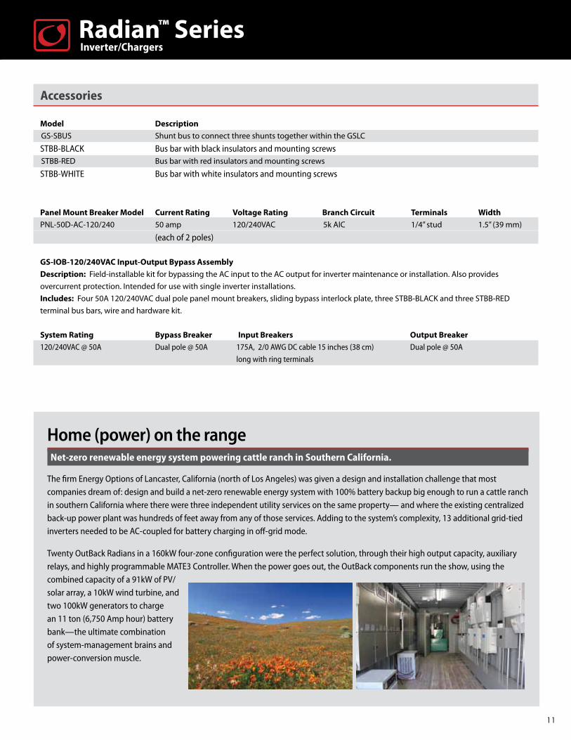
Home (power) on the rangeNet-zero renewable energy system powering cattle ranch in Southern California.
The firm Energy Options of Lancaster, California (north of Los Angeles) was given a design and installation challenge that most companies dream of: design and build a net-zero renewable energy system with 100% battery backup big enough to run a cattle ranch in southern California where there were three independent utility services on the same property— and where the existing centralized back-up power plant was hundreds of feet away from any of those services. Adding to the system’s complexity, 13 additional grid-tied inverters needed to be AC-coupled for battery charging in off-grid mode.
Twenty OutBack Radians in a 160kW four-zone configuration were the perfect solution, through their high output capacity, auxiliary relays, and highly programmable MATE3 Controller. When the power goes out, the OutBack components run the show, using the combined capacity of a 91kW of PV/solar array, a 10kW wind turbine, and two 100kW generators to charge an 11 ton (6,750 Amp hour) battery bank—the ultimate combination of system-management brains and power-conversion muscle.
Inverter/ChargersRadian™ Series
Energy StorageAs the demand for renewable energy increases, the needs of system integrators and installers are rapidly evolving as well. OutBack is responding by engineering its acclaimed line of balance-of-system components into preassembled systems to give installers the best of both worlds: OutBack quality in a more easily specified and installed package. Battery back-up capability has always been in the “brand DNA” of OutBack’s acclaimed off-grid and grid-interactive inverter/chargers. Now system installers can design a total power solution around the brand they most trust.
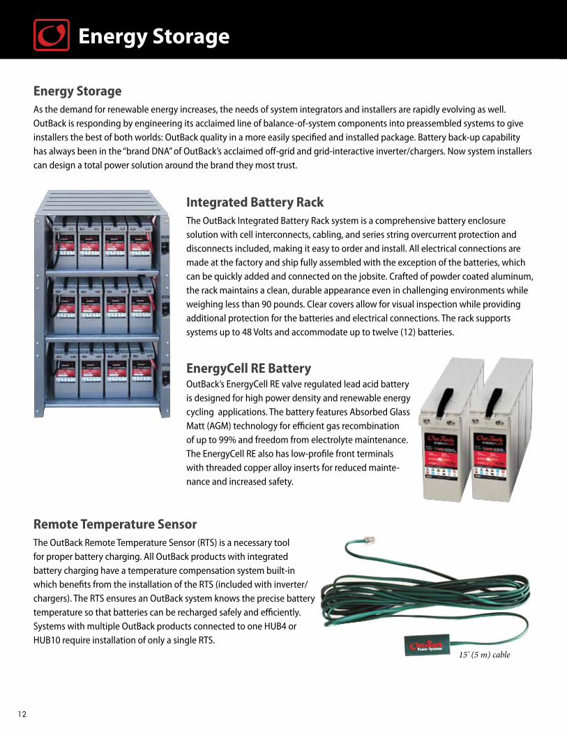
Integrated Battery Rack The OutBack Integrated Battery Rack system is a comprehensive battery enclosure solution with cell interconnects, cabling, and series string overcurrent protection and disconnects included, making it easy to order and install. All electrical connections are made at the factory and ship fully assembled with the exception of the batteries, which can be quickly added and connected on the jobsite. Crafted of powder coated aluminum, the rack maintains a clean, durable appearance even in challenging environments while weighing less than 90 pounds. Clear covers allow for visual inspection while providing additional protection for the batteries and electrical connections. The rack supports systems up to 48 Volts and accommodate up to twelve (12) batteries.
EnergyCell RE BatteryOutBack’s EnergyCell RE valve regulated lead acid battery is designed for high power density and renewable energy cycling applications. The battery features Absorbed Glass Matt (AGM) technology for efficient gas recombination of up to 99% and freedom from electrolyte maintenance. The EnergyCell RE also has low-profile front terminals with threaded copper alloy inserts for reduced mainte-nance and increased safety.
Remote Temperature SensorThe OutBack Remote Temperature Sensor (RTS) is a necessary tool for proper battery charging. All OutBack products with integrated battery charging have a temperature compensation system built-in which benefits from the installation of the RTS (included with inverter/chargers). The RTS ensures an OutBack system knows the precise battery temperature so that batteries can be recharged safely and efficiently. Systems with multiple OutBack products connected to one HUB4 or HUB10 require installation of only a single RTS.
Energy Storage
15' (5 m) cable
12

Energy Storage
Integrated Battery Rack Specifications
IBR-3-48-175 Dimensions H x W x D 48.6 x 27.0 x 24.4” (123.4 x 68.6 x 61.9 cm)Weight 89 lbs (40.4 kg) without batteriesPhysical 0.125-inch thick aluminum enclosure with FLEXware silver finish; plated copper bus bars and clear protective covers. Ships fully assembled (except for batteries)String Overcurrent Protection 175 amps DCGauge of conductors 1/0 AWGCapacity Up to twelve (12) EnergyCell RE batteries Nominal System Voltage 48VDCSupported batteries* EnergyCell 200RE, EnergyCell 170RE
EnergyCell RE Front Terminal Battery Specifications
EnergyCell 170RE EnergyCell 200RECells Per Unit 6 6Voltage Per Unit 12VDC 12VDCOperating Temperature Range (with temperature compensation) Discharge: -40°F (-40°C) to 160°F (71°C) Discharge: -40°F (-40°C) to 160°F (71°C) Charge: -10°F (-23°C) to 140°F (60°C) Charge: -10°F (-23°C) to 140°F (60°C) Optimal Operating Temperature Range 74°F (23°C) to 80°F (27°C) 74°F (23°C) to 80°F (27°C)“Recommended Maximum Charging Current Limit Per String” 25 amps DC 30 amps DC Float Charging Voltage 13.62 to 13.8VDC / unit average at 77°F (25°C) 13.62 to 13.8VDC / unit average at 77°F (25°C)
“Equalization and CycleService Charging Limits “ 14.4 to 14.8VDC / unit average at 77°F (25°C) 14.4 to 14.8VDC / unit average at 77°F (25°C) Self Discharge Battery can be stored up to 6 months at 77°F (25°C) before a freshening charge is required. Batteries stored at temperatures greater than 77°F (25°C) will require recharge sooner than batteries stored at lower temperatures. Temperature Compensation Factor (Charging) 5mV per degree C per cell (2V) 5mV per degree C per cell (2V)Terminal Threaded copper alloy insert terminal Threaded copper alloy insert terminal to accept ¼-20 UNC bolt to accept ¼-20 UNC boltTerminal Hardware Initial Torque 110 in-lbs (12.4 Nm) 110 in-lbs (12.4 Nm)Weight 115 lbs (52 kg) 131 lbs ( 60 kg)Dimensions H x D x W* 11.14 x 22.01 x 4.95” (28.3 x 55.9 x 12.6 cm) 12.60 x 22.01 x 4.95” (32.0 x 55.09 x 12.6 cm)
* Batteries to be installed with 0.5 in (12.7 mm) spacing minimum and free air ventilation.
Discharge in Hours Ampere Hour Capacity to 1.75 Volts Per Cell at 77°F (25°C) EnergyCell 170RE EnergyCell 200RE
1 89.1 103
3 114.2 132
4 120.6 139.6
5 125.9 145.5
8 137 158.4
12 145.3 168
20 153.8 178
24 157 181.4
48 163.9 189.6
100 170 200
13
FLEXpower ONE Specifications
For 120Vac/60Hz applications Pre-wired Systems* Description FP1-1 VFX3524 3.5kW FLEXpower ONE, Pre-wired AC and DC boxes with 120VAC Bypass, Type B Outlet, 250A DC breaker, GFDI, 80A charge controller breaker, MATE2, HUB4, RTS, FLEXmax 80, FLEXnet DC and surge protectorFP1-2 VFX3648 3.6kW FLEXpower ONE, Pre-wired AC and DC boxes with 120VAC Bypass, Type B Outlet, 175A DC breaker, GFDI, 80A charge controller breaker, MATE2, HUB4, RTS, FLEXmax 80, FLEXnet DC and surge protectorFP1-3 GVFX3524 3.5kW FLEXpower ONE, Pre-wired AC and DC boxes with 120VAC Bypass, Type B Outlet, 250A DC breaker, GFDI, 80A charge controller breaker, MATE2, HUB4, RTS, FLEXmax 80, FLEXnet DC and surge protectorFP1-4 GVFX3648 3.6kW FLEXpower ONE, Pre-wired AC and DC boxes with 120VAC Bypass, Type B Outlet, 175A DC breaker, GFDI, 80A charge controller breaker, MATE2, HUB4, RTS, FLEXmax 80, FLEXnet DC and surge protectorFP1-25 GTFX3048 3kW FLEXpower ONE, Pre-wired AC and DC boxes with 120VAC Bypass, Type B Outlet, 175A DC breaker, GFDI, 80A charge controller breaker, MATE2, HUB4, RTS, FLEXmax 80 and surge protector (FN-DC not included)FP1-26 FX3048T 3kW FLEXpower ONE, Pre-wired AC and DC boxes with 120VAC Bypass, Type B Outlet, 175A DC breaker, GFDI, 80A charge controller breaker, MATE2, HUB4, RTS, FLEXmax 80, FLEXnet DC and surge protectorFP1-27 FX2524T 2.5kW FLEXpower ONE, Pre-wired AC and DC boxes with 120VAC Bypass, Type B Outlet, 175A DC breaker, GFDI, 80A charge controller breaker, MATE2, HUB4, RTS, FLEXmax 80, FLEXnet DC and surge protector FP1-36 GTFX2524-HI 2.5kW FLEXpower ONE for Hawaii market, Pre-wired AC and DC boxes with 120VAC Bypass, Type B Outlet, 250A DC breaker, GFDI, 80A charge controller breaker, MATE2, HUB4, RTS, FLEXmax 80 and surge protector (FN-DC not included)FP1-37 GTFX3048-HI 3kW FLEXpower ONE for Hawaii market, Pre-wired AC and DC boxes with 120VAC Bypass, Type B Outlet, 175A DC breaker, GFDI, 80A charge controller breaker, MATE2, HUB4, RTS, FLEXmax 80 and surge protector (FN-DC not included)For 230VAC/50Hz applications FP1-5 VFX3024E 3kW FLEXpower ONE, Pre-wired AC and DC boxes with 230VAC Bypass, European Outlet, 250A DC breaker, GFDI, 80A charge controller breaker, MATE2, HUB4, RTS, FLEXmax 80, FLEXnet DC and surge protector FP1-6 VFX3048E 3kW FLEXpower ONE, Pre-wired AC and DC boxes with 230VAC Bypass, European Outlet, 175A DC breaker, GFDI, 80A charge controller breaker, MATE2, HUB4, RTS, FLEXmax 80, FLEXnet DC and surge protector FP1-34 GVFX3024E 3kW FLEXpower ONE, Pre-wired AC and DC boxes with 230VAC Bypass, European Outlet, 250A DC breaker, GFDI, 80A charge controller breaker, MATE2, HUB4, RTS, FLEXmax 80, FLEXnet DC and surge protector FP1-35 GVFX3048E 3kW FLEXpower ONE, Pre-wired AC and DC boxes with 230VAC Bypass, European Outlet, 175A DC breaker, GFDI, 80A charge controller breaker, MATE2, HUB4, RTS, FLEXmax 80, FLEXnet DC and surge protectorWeight Unit 98 lbs (44.5 kg) Shipping 109 lbs (49.4 kg) Dimensions (H x W x L) Unit 12.88 x 19.69 x 33.44” (32.72 x 50.01 x 84.94 cm) Shipping 17 x 22.75 x 38” (43.18 x 57.79 x 96.52 cm)
* Individual FLEXpower ONE components carry all necessary ETL certifications. * Additional configurations available.
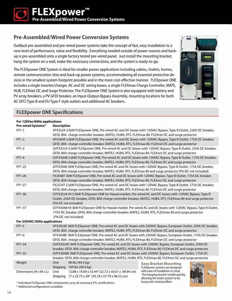
Pre-Assembled/Wired Power Conversion SystemsOutBack pre-assembled and pre-wired power systems take the concept of fast, easy installation to a new level of performance, value and flexibility. Everything needed outside of power sources and back-up is pre-assembled onto a single factory tested pre-wired panel. Just install the mounting bracket, hang the system on a wall, make the necessary connections, and the system is ready-to-go.
The FLEXpower ONE System is ideal for smaller power applications including cabins, chalets, homes, remote communication sites and back-up power systems, accommodating all essential protective de-vices in the smallest system footprint possible and in the most cost-effective manner. FLEXpower ONE includes a single inverter/charger, AC and DC wiring boxes, a single FLEXmax Charge Controller, MATE, HUB, FLEXnet DC and Surge Protector. The FLEXpower ONE System is also equipped with battery and PV array breakers, a PV GFDI breaker, an Input-Output-Bypass Assembly, mounting locations for both AC GFCI Type B and EU Type F style outlets and additional AC breakers.
Easy Bracket MountingFLEXpower systems are designed with ease of installation in mind. The hanging bracket installs quickly, allowing the entire system to be hung with minimal effort.
14
Pre-Assembled/Wired Power Conversion SystemsFLEXpower™
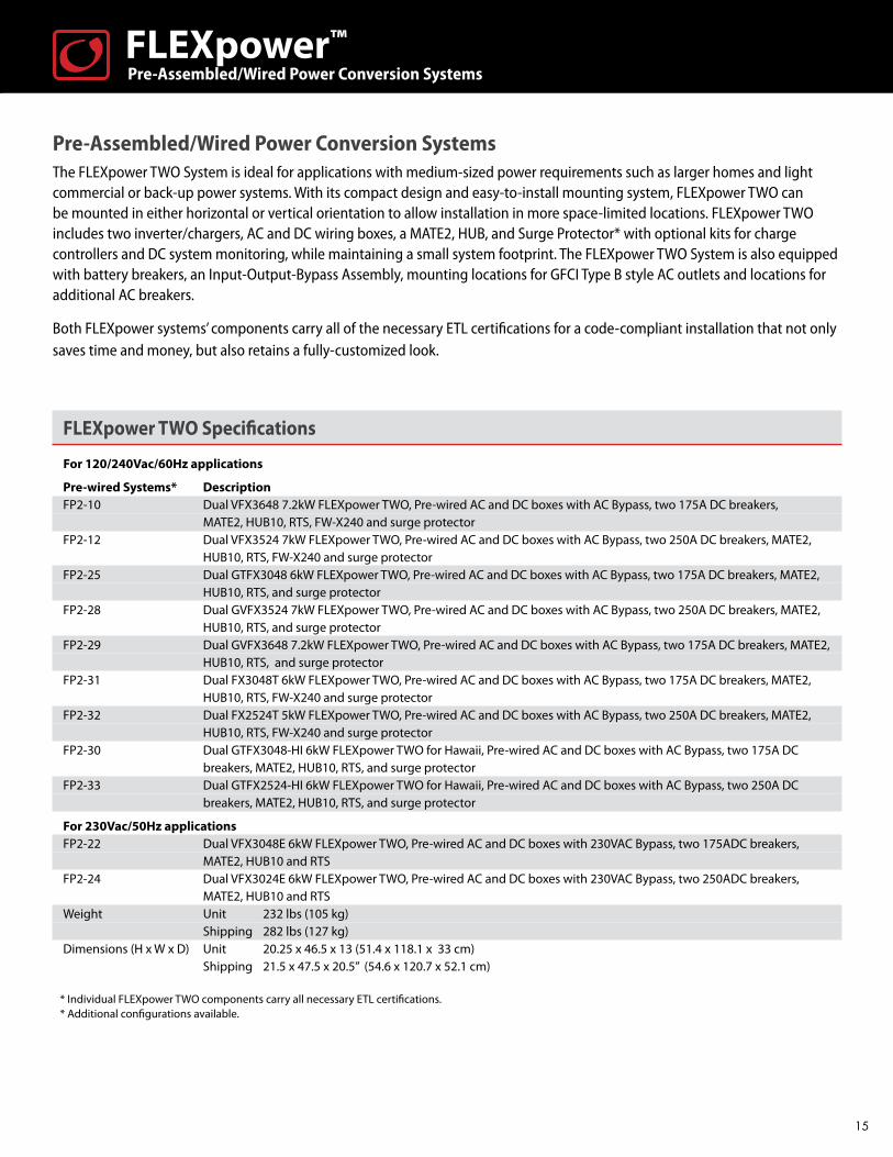
Pre-Assembled/Wired Power Conversion SystemsThe FLEXpower TWO System is ideal for applications with medium-sized power requirements such as larger homes and light commercial or back-up power systems. With its compact design and easy-to-install mounting system, FLEXpower TWO can be mounted in either horizontal or vertical orientation to allow installation in more space-limited locations. FLEXpower TWO includes two inverter/chargers, AC and DC wiring boxes, a MATE2, HUB, and Surge Protector* with optional kits for charge controllers and DC system monitoring, while maintaining a small system footprint. The FLEXpower TWO System is also equipped with battery breakers, an Input-Output-Bypass Assembly, mounting locations for GFCI Type B style AC outlets and locations for additional AC breakers.
Both FLEXpower systems’ components carry all of the necessary ETL certifications for a code-compliant installation that not only saves time and money, but also retains a fully-customized look.
FLEXpower TWO Specifications
For 120/240Vac/60Hz applications
Pre-wired Systems* Description FP2-10 Dual VFX3648 7.2kW FLEXpower TWO, Pre-wired AC and DC boxes with AC Bypass, two 175A DC breakers, MATE2, HUB10, RTS, FW-X240 and surge protectorFP2-12 Dual VFX3524 7kW FLEXpower TWO, Pre-wired AC and DC boxes with AC Bypass, two 250A DC breakers, MATE2, HUB10, RTS, FW-X240 and surge protectorFP2-25 Dual GTFX3048 6kW FLEXpower TWO, Pre-wired AC and DC boxes with AC Bypass, two 175A DC breakers, MATE2, HUB10, RTS, and surge protectorFP2-28 Dual GVFX3524 7kW FLEXpower TWO, Pre-wired AC and DC boxes with AC Bypass, two 250A DC breakers, MATE2, HUB10, RTS, and surge protectorFP2-29 Dual GVFX3648 7.2kW FLEXpower TWO, Pre-wired AC and DC boxes with AC Bypass, two 175A DC breakers, MATE2, HUB10, RTS, and surge protectorFP2-31 Dual FX3048T 6kW FLEXpower TWO, Pre-wired AC and DC boxes with AC Bypass, two 175A DC breakers, MATE2, HUB10, RTS, FW-X240 and surge protector FP2-32 Dual FX2524T 5kW FLEXpower TWO, Pre-wired AC and DC boxes with AC Bypass, two 250A DC breakers, MATE2, HUB10, RTS, FW-X240 and surge protector FP2-30 Dual GTFX3048-HI 6kW FLEXpower TWO for Hawaii, Pre-wired AC and DC boxes with AC Bypass, two 175A DC breakers, MATE2, HUB10, RTS, and surge protectorFP2-33 Dual GTFX2524-HI 6kW FLEXpower TWO for Hawaii, Pre-wired AC and DC boxes with AC Bypass, two 250A DC breakers, MATE2, HUB10, RTS, and surge protector
For 230Vac/50Hz applications FP2-22 Dual VFX3048E 6kW FLEXpower TWO, Pre-wired AC and DC boxes with 230VAC Bypass, two 175ADC breakers, MATE2, HUB10 and RTS FP2-24 Dual VFX3024E 6kW FLEXpower TWO, Pre-wired AC and DC boxes with 230VAC Bypass, two 250ADC breakers, MATE2, HUB10 and RTS Weight Unit 232 lbs (105 kg) Shipping 282 lbs (127 kg) Dimensions (H x W x D) Unit 20.25 x 46.5 x 13 (51.4 x 118.1 x 33 cm) Shipping 21.5 x 47.5 x 20.5” (54.6 x 120.7 x 52.1 cm)
* Individual FLEXpower TWO components carry all necessary ETL certifications. * Additional configurations available.
15
Pre-Assembled/Wired Power Conversion SystemsFLEXpower™
Inverter Chargers
Pure sine-wave technologyThe appliances and electronics in a home or business need a clean, undistorted AC sine wave signal to operate properly. OutBack inverters use proprietary digital switching technology coupled to the custom, low-loss/high-efficiency transformer to deliver sine-wave AC power that’s actually cleaner than the electricity many utility companies can generate.
On-board intelligenceAn OutBack inverter can sense power outages, surges, or any-thing else affecting your service—and takes immediate steps to provide a back-up (including starting a generator). It even has a standby/sleep mode to conserve power, waking up when your lights or appliances require power, for example. An OutBack inverter can protect itself from potential faults including an AC short and low/high battery voltage. OutBack inverters have superior surge capabilities and smarter battery-charging algorithms—and almost all settings are user-adjustable for complete application customization.
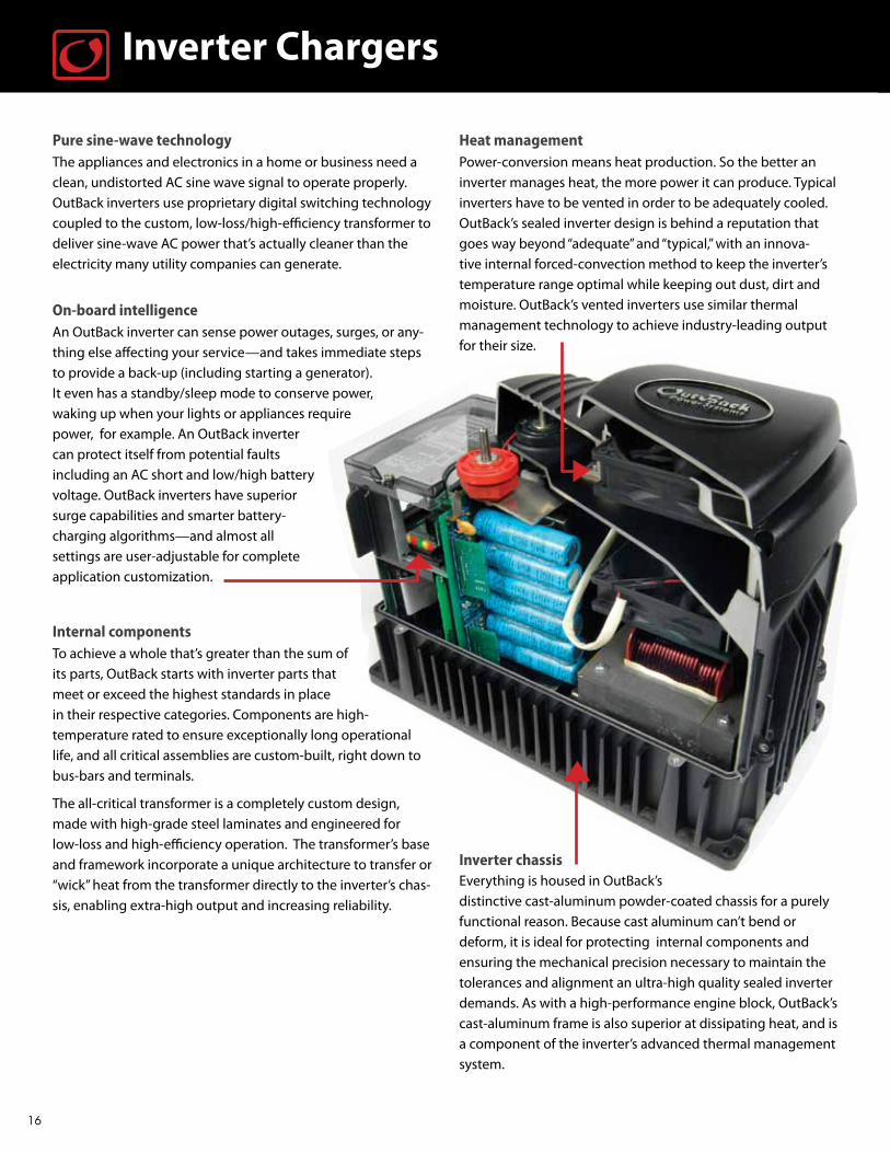
Internal componentsTo achieve a whole that’s greater than the sum of its parts, OutBack starts with inverter parts that meet or exceed the highest standards in place in their respective categories. Components are high-temperature rated to ensure exceptionally long operational life, and all critical assemblies are custom-built, right down to bus-bars and terminals.
The all-critical transformer is a completely custom design, made with high-grade steel laminates and engineered for low-loss and high-efficiency operation. The transformer’s base and framework incorporate a unique architecture to transfer or “wick” heat from the transformer directly to the inverter’s chas-sis, enabling extra-high output and increasing reliability.
Heat managementPower-conversion means heat production. So the better an inverter manages heat, the more power it can produce. Typical inverters have to be vented in order to be adequately cooled. OutBack’s sealed inverter design is behind a reputation that goes way beyond “adequate” and “typical,” with an innova-tive internal forced-convection method to keep the inverter’s temperature range optimal while keeping out dust, dirt and moisture. OutBack’s vented inverters use similar thermal management technology to achieve industry-leading output for their size.
Inverter chassisEverything is housed in OutBack’s distinctive cast-aluminum powder-coated chassis for a purely functional reason. Because cast aluminum can’t bend or deform, it is ideal for protecting internal components and ensuring the mechanical precision necessary to maintain the tolerances and alignment an ultra-high quality sealed inverter demands. As with a high-performance engine block, OutBack’s cast-aluminum frame is also superior at dissipating heat, and is a component of the inverter’s advanced thermal management system.
16
Inside the “Master of the Off-Grid”The heart of any renewable or back-up energy system, an inverter takes DC electricity from a source such as a solar panel, water
or wind turbine, and converts it into useable AC that can run lighting, appliances, communications, entertainment—and also keep
back-up batteries fully-charged and ready. OutBack bi-directional inverters/chargers, unlike grid-direct inverters, can also convert
electricity from the utility grid or a generator to DC power to recharge batteries. This allows the user the maximum flexibility in
configuring and providing power with or without the grid being available.
OutBack’s FX and GFX-series inverters earned their reputation not by being “built like tanks” in the clichéd sense—they
are actually built better than that, with selected models used on tanks and other fighting vehicles for power in the field.
Unprecedented build-quality in this case is no luxury. It is a necessity in order to achieve the reliability users demand in harsh
operating conditions where failure is never an option and a spare might be days or even weeks away.
Because OutBack specializes in off-grid and grid-interactive inverters which inherently have higher levels of operational
sophistication and on-board intelligence than simple grid-tied inverters, the OutBack inverter design is purely form following
function—in this case, the perfect form for achieving the optimum balance between energy-management brains and
power-conversion muscle.
Inverter Chargers
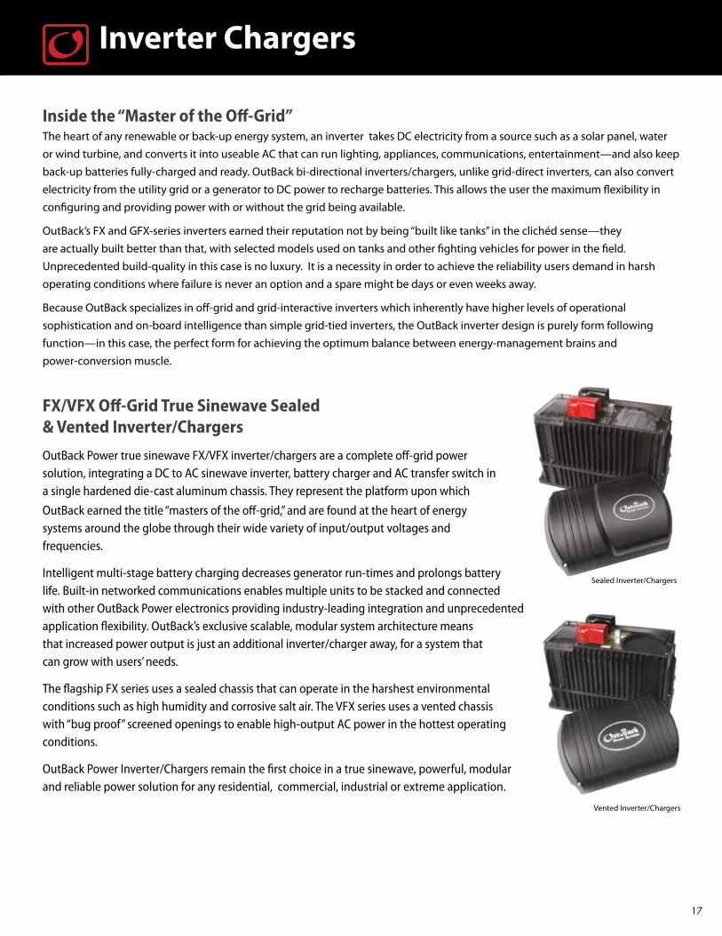
FX/VFX Off-Grid True Sinewave Sealed & Vented Inverter/Chargers
OutBack Power true sinewave FX/VFX inverter/chargers are a complete off-grid power solution, integrating a DC to AC sinewave inverter, battery charger and AC transfer switch in a single hardened die-cast aluminum chassis. They represent the platform upon which
OutBack earned the title “masters of the off-grid,” and are found at the heart of energy systems around the globe through their wide variety of input/output voltages and frequencies.
Intelligent multi-stage battery charging decreases generator run-times and prolongs battery life. Built-in networked communications enables multiple units to be stacked and connected with other OutBack Power electronics providing industry-leading integration and unprecedented application flexibility. OutBack’s exclusive scalable, modular system architecture means that increased power output is just an additional inverter/charger away, for a system that can grow with users’ needs.
The flagship FX series uses a sealed chassis that can operate in the harshest environmental conditions such as high humidity and corrosive salt air. The VFX series uses a vented chassis with “bug proof” screened openings to enable high-output AC power in the hottest operating conditions.
OutBack Power Inverter/Chargers remain the first choice in a true sinewave, powerful, modular and reliable power solution for any residential, commercial, industrial or extreme application.
17

Off-Grid 60Hz / 120VInverter Chargers
FX & VFX Series Specifications - 60Hz / 120V Sealed Models Vented Models FX2012T FX2524T FX3048T VFX2812 VFX3524 VFX3648 Nominal DC Input Voltage 12VDC 24VDC 48VDC 12VDC 24VDC 48VDC Continuous Power Rating at 25°C (77°F) 2000VA 2500VA 3000VA 2800VA 3500VA 3600VA AC Voltage/Frequency 120VAC / 60Hz 120VAC / 60Hz 120VAC / 60Hz 120VAC / 60Hz 120VAC / 60Hz 120VAC / 60Hz Continuous AC RMS Output at 25°C (77°F) 17 amps AC 20.8 amps AC 25 amps AC 23.3 amps AC 29.2 amps AC 30 amps AC Idle Power Full ~ 20W ~ 20W ~ 23W ~ 20W ~ 20W ~23W Search ~ 6W ~ 6W ~ 6W ~ 6W ~ 6W ~ 6W Typical Efficiency 90% 92% 93% 90% 92% 93% Total Harmonic Distortion Typical 2% 2% 2% 2% 2% 2% Maximum 5% 5% 5% 5% 5% 5% Output Voltage Regulation ±2% ±2% ±2% ±2% ±2% ±2% Maximum Output Current Peak 56 amps AC 70 amps AC 70 amps AC 56 amps AC 70 amps AC 70 amps AC RMS 40 amps AC 50 amps AC 50 amps AC 40 amps AC 50 amps AC 50 amps AC AC Overload Capability Surge 4800VA 6000VA 6000VA 4800VA 6000VA 6000VA 5 Seconds 4000VA 4800VA 4800VA 4000VA 5000VA 5000VA 30 Minutes 2500VA 3200VA 3200VA 3200VA 4000VA 4000VA AC Input Current Maximum 60 amps AC 60 amps AC 60 amps AC 60 amps AC 60 amps AC 60 amps AC AC Input Voltage Range (MATE Adjustable) 80 to 150VAC 80 to 150VAC 80 to 150VAC 80 to 150VAC 80 to 150VAC 80 to 150VAC AC Input Frequency Range 54 to 66Hz 54 to 66Hz 54 to 66Hz 54 to 66Hz 54 to 66Hz 54 to 66Hz DC Input Voltage Range 10.5 to 17VDC 21 to 34VDC 42 to 68VDC 10.5 to 17VDC 21 to 34VDC 42 to 68VDC Continuous Battery Charger Output 80 amps DC 55 amps DC 35 amps DC 125 amps DC 82 amps DC 45 amps DC Temperature Range Rated 0°C to 50°C (power derated above 25°C) 0°C to 50°C (power derated above 25°C) Maximum* -25°C to 60°C -25°C to 60°C Certifications ETL Listed to UL1741 ETL Listed to UL1741 Warranty Standard 5 year Standard 5 year Weight Unit 62 lbs (29 kg) 61 lbs (28 kg) Shipping 67 lbs (31 kg) 67 lbs (31 kg) Dimensions H x W x L Unit 13 x 8.25 x 16.25” (33 x 21 x 41 cm) 12 x 8.25 x 16.25” (30 x 21 x 41 cm) Shipping 21.75 x 13 x 22” (55 x 33 x 56 cm) 21.75 x 13 x 22” (55 x 33 x 56 cm)
18
Powering change in paradiseMini-grid powering the community of Melano, Borneo
A fishing and pepper-farming village at the tip of East Malaysia, Melano is exceptionally isolated—unreachable by land, and accessible only after a long road-trip followed by an even longer boat trip. With both population and economic growth in place, Melano has reached the point where its homes, police station, community library, and religious facilities are primed for modern conveniences and appliances powered by electricity. That’s part of the reason why it was selected for the evaluation of a planned roll-out of mini-grid electrical systems that will ultimately serve similar communities throughout Malaysia.
For this pioneering effort, two OutBack FLEXware systems were selected to run the 18.4kW mini-grid installation. High output from a relatively compact size made FLEXware an ideal choice in a place where every component must be brought in by small boat and hand-carried to the installation site on poles, and where reliability is paramount because a replacement is literally a voyage away.
As the Smart Grid Observer* noted when citing a recent Pike Research report on remote micro-grids, “in the village power systems sub-segment, OutBack Power Technologies, which offers customized inverters and load controls optimized for rugged, remote applications, is by far and away the leading vendor.”*June 15, 2012, “Remote Microgrids Poised for Growth”

FX & VFX Series Specifications - 60Hz / 230V Sealed Models Vented Models
FX2024WT FX2348WT VFX3024W VFX3048W Nominal DC Input Voltage 24VDC 48VDC 24VDC 48VDC Continuous Power Rating at 25°C 2000VA 2300VA 3000VA 3000VA AC Voltage/Frequency 230VAC 60Hz 230VAC 60Hz 230VAC 60Hz 230VAC 60Hz Continuous AC RMS Output at 25°C 8.7 amps AC 10 amps AC 13 amps AC 13 amps AC Idle Power Full ≈ 20W ≈ 23W ≈ 20W ≈ 23W Search ≈ 6W ≈ 6W ≈ 6W ≈ 6W Typical Efficiency 92% 93% 92% 93% Total Harmonic Distortion Typical (V) 2% 2% 2% 2% Maximum (V) <5% <5% <5% <5% Output Voltage Regulation ± 2% ± 2% ± 2% ± 2% Maximum Output Current Peak 35 amps AC 35 amps AC 35 amps AC 35 amps AC RMS 25 amps AC 25 amps AC 25 amps AC 25 amps AC AC Overload Capability Surge 5750VA 5750VA 5750VA 5750VA 5 Second 4800VA 4800VA 4800VA 4800VA 30 Minutes 3100VA 3100VA 3100VA 3100VA AC Input Current Maximum 30 amps AC 30 amps AC 30 amps AC 30 amps AC AC Input Voltage Range (MATE Adjustable) 160 to 300VAC 160 to 300VAC 160 to 300VAC 160 to 300VAC AC Input Frequency Range 54 to 66Hz 54 to 66Hz 54 to 66Hz 54 to 66Hz DC Input Voltage Range 21.0 to 34.0VDC 42.0 to 68.0VDC 21.0 to 34.0VDC 42.0 to 68.0VDC Continuous Battery Charge Output 55 amps DC 35 amps DC 85 amps DC 45 amps DC Temperature Range Rated 0°C to 50°C (power derated above 25°C) 0°C to 50°C (power derated above 25°C) Maximum* -25°C to 60°C -25°C to 60°C Warranty Standard 5 year Standard 5 year Weight Unit 62 lbs (31 kg) 61 lbs (31 kg) Shipping 67 lbs (31 kg) 67 lbs (31 kg) Dimensions (H x W x L) Unit 13 x 8.25 x 16.25” (33 x 21 x 41 cm) 12 x 8.25 x 16.25” (30 x 21 x 41 cm) Shipping 21.75 x 13 x 22” (55 x 33 x 56 cm) 21.75 x 13 x 22” (55 x 33 x 56 cm) * Functions, but does not necessarily meet all component specifications.
Off-Grid 60Hz / 230VInverter Chargers
Scaling new heights in power generationRifugio Alimonta climbing lodge in the Italian Alps
The Dolomites have been a destination of world-class mountaineers for centuries. Its iconic peaks draw climbers and hikers from around the world, attracted by both the beauty and the challenge. The Rifugio (refuge) Alimonta was conceived and built to be their home away from home while exploring the peaks: a combination base, lodge and cafeteria at 8,464 ft./2,580m altitude beautifully integrated into its magnificent surroundings. Of course, being several kilometers higher than the closest electrical grid means that
offgrid operation is a given—and with “next day air” wishful thinking, the choice of of-grid system components was driven by which brand could provide the ultimate balance between reliability and performance. Based on that criteria, the choice of off-grid powercomponents for this installation came down to a field of one: OutBack. After all, for anyone or anything representing a peak of excel-lence the old saying holds true: it’s always lonely at the top.
19

N-Series FX & VFX Specifications 50Hz / 100V For Japan
Sealed Models Vented Models FX2224NT FX2448NT VFX2724N VFX2848N Nominal DC Input Voltage 24VDC 48VDC 24VDC 48VDC Continuous Power Rating at 25°C 2200VA 2400VA 2700VA 2800VA AC Voltage/Frequency 100VAC / 50Hz 100VAC / 50Hz 100VAC / 50Hz 100VAC / 50Hz Continuous AC RMS Output at 25°C 22 amps AC 24 amps AC 27 amps AC 28 amps AC Idle Power Full ~20W ~23W ~20W ~23W Search ~6W ~6W ~6W ~6W Typical Efficiency 92% 93% 92% 93% Total Harmonic Distortion Typical 2% 2% 2% 2% Maximum <5% <5% <5% <5% Output Voltage Regulation ± 2% ± 2% ± 2% ± 2% Maximum Output Current Peak 70 amps AC 70 amps AC 70 amps AC 70 amps AC RMS 50 amps AC 50 amps AC 50 amps AC 50 amps AC AC Overload Capability Surge 5000VA 5000VA 5000VA 5000VA 5 Seconds 4100VA 4100VA 4100VA 4100VA 30 Minutes 2800VA 2800VA 3000VA 3000VA AC Input Current Maximum 60 amps AC 60 amps AC 60 amps AC 60 amps AC AC Input Voltage Range (adjustable) 66 to 120 amps AC 66 to 120 amps AC 66 to 120 amps AC 66 to 120 amps AC AC Input Frequency Range 44 to 56Hz 44 to 56Hz 44 to 56Hz 44 to 56Hz DC Input Voltage Range 21 to 34VDC 42 to 68VDC 21 to 34VDC 42 to 68VDC Continuous Battery Charge Output 50 amps DC 35 amps DC 60 amps DC 35 amps DC Temperature Range Rated 0°C to 50°C (power derated above 25°C) 0°C to 50°C (power derated above 25°C) Maximum* -25°C to 60°C -25°C to 60°C Warranty Standard 5 year Standard 5 year Weight Unit 28.0 kg 27.6 kg Shipping 30.0 kg 29.0 kg Dimensions (H x W x L) Unit 33 x 21 x 41 cm 30 x 21 x 41 cm Shipping 55 x 33 x 56 cm 55 x 33 x 56 cm
Off-Grid 50Hz / 100VInverter Chargers
* Functions, but does not necessarily meet all component specifications.
Keeping an ancient culture up-to-dateTumul K’in Mayan School, Belize rainforest
Modern-day descendants of the venerable Mayan civilization received a boost for education for their children when a European benefactor group provided financial assistance for a new school and cultural center in the rainforest near the town of Toledo in Belize. Because access to the location is by river using a longboat, the power system—which has the dual job of providing energy as well as educating students in sustainable technology—had to deliver high output from a relatively compact size and have the reliability to operate dependably in an isolated location where a replacement is not just around the corner. System designer/installers chose the OutBack FLEXware 500 to provide renewable energy and a teaching platform for the school’s 30 students. Because the facility also serves as a cultural center for traditional Mayan ceremonies, celebrations and gather-ings, its state-of-the art renewable energy system has become a benchmark throughout the region for the potential of solar power to improve quality of life.
20
J-Series 50Hz / 120V For Jamica and other markets
Sealed Models Vented Models FX2024JT VFX3024J
Nominal DC Input Voltage 24VDC 24VDCContinuous Power Rating at 25°C 2000VA 3000VAAC Voltage/Frequency 120VAC 50Hz 120VAC 50HzContinuous AC RMS Output at 25°C 16.7 amps AC 25 amps ACIdle Power Full ≈ 20W ≈ 20W Search ≈ 6W ≈ 6WTypical Efficiency 92% 92%Total Harmonic Distortion Typical (V) 2% 2% Maximum (V) <5% <5% Output Voltage Regulation ± 2% ± 2%Maximum Output Current Peak 70 amps AC 70 amps AC RMS 50 amps AC 50 amps ACAC Overload Capability Surge 6000VA 6000VA 5 Second 4800VA 4800VA 30 Minutes 3100VA 3100VAAC Input Current Maximum 60 amps AC 60 amps ACAC Input Voltage Range (MATE Adjustable) 80 to 150VAC 80 to 150VACAC Input Frequency Range 44 to 56Hz 44 to 56HzDC Input Voltage Range 21.0 to 34.0VDC 21.0 to 34.0VDCContinuous Battery Charge Output 55 amps DC 55 amps DC 85 amps DCTemperature Range Rated 0°C to 50°C (power derated above 25°C) 0°C to 50°C (power derated above 25°C) Maximum* -25°C to 60°C -25°C to 60°CWarranty Standard 5 year Standard 5 yearWeight Unit 62 lbs (29 kg) 61 lbs (28 kg) Shipping 67 lbs (31 kg) 67 lbs (31 kg)Dimensions (H xW x L) Unit 13 x 8.25 x 16.25” (33 x 21 x 41 cm) 12 x 8.25 x 16.25” (30 x 21 x 41 cm) Shipping 21.75 x 13 x 22” (55 x 33 x 56 cm) 21.75 x 13 x 22” (55 x 33 x 56 cm)
* Functions, but does not necessarily meet all component specifications.
Off-Grid 50Hz / 120VInverter Chargers
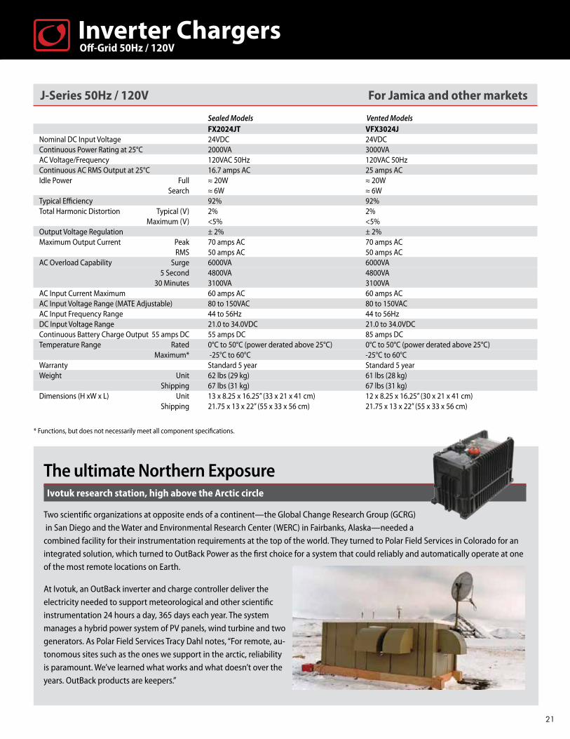
The ultimate Northern ExposureIvotuk research station, high above the Arctic circle
Two scientific organizations at opposite ends of a continent—the Global Change Research Group (GCRG) in San Diego and the Water and Environmental Research Center (WERC) in Fairbanks, Alaska—needed a combined facility for their instrumentation requirements at the top of the world. They turned to Polar Field Services in Colorado for an integrated solution, which turned to OutBack Power as the first choice for a system that could reliably and automatically operate at one of the most remote locations on Earth.
At Ivotuk, an OutBack inverter and charge controller deliver the electricity needed to support meteorological and other scientific instrumentation 24 hours a day, 365 days each year. The system manages a hybrid power system of PV panels, wind turbine and two generators. As Polar Field Services Tracy Dahl notes, “For remote, au-tonomous sites such as the ones we support in the arctic, reliability is paramount. We’ve learned what works and what doesn’t over the years. OutBack products are keepers.”
21

FX & VFX Series Specifications 50Hz / 230V For Europe and other international markets
Sealed Models Vented Models FX2012ET FX2024ET FX2348ET VFX2612E VFX3024E VFX3048E
Nominal DC Input Voltage 12VDC 24VDC 48VDC 12VDC 24VDC 48VDC Continuous Power Rating at 25°C (77°F) 2000VA 2000VA 2300VA 2600VA 3000VA 3000VAAC Voltage/Frequency 230VAC 50Hz 230VAC 50Hz 230VAC 50Hz 230VAC 50Hz 230VAC 50Hz 230VAC 50Hz Continuous AC RMS Output at 25°C (77°F) 8.7 amps AC 8.7 amps AC 10.0 amps AC 11.3 amps AC 13.0 amps AC 13.0 amps ACIdle Power Full ~ 20W ~ 20W ~ 23W ~ 20W ~ 20W ~ 23W Search ~ 6W ~ 6W ~6W ~ 6W ~ 6W ~ 6WTypical Efficiency 90% 92% 93% 90% 92% 93%Total Harmonic Distortion Typical 2% 2% 2% 2% 2% 2% Maximum 5% 5% 5% 5% 5% 5%Output Voltage Regulation ± 2% ± 2% ± 2% ± 2% ± 2% ± 2%Maximum Output Current Peak 28 amps AC 35 amps AC 35 amps AC 28 amps AC 35 amps AC 35 amps AC RMS 20 amps AC 25 amps AC 25 amps AC 20 amps AC 25 amps AC 25 amps ACAC Overload Capability Surge 4600VA 5750VA 5750VA 4600VA 5750VA 5750VA 5 Second 4000VA 4800VA 4800VA 4000VA 4800VA 4800VA 30 Minutes 2500VA 3100VA 3100VA 3100VA 3300VA 3 300VAAC Input Current Maximum 30 amps AC 30 amps AC 30 amps AC 30 amps AC 30 amps AC 30 amps AC AC Input Voltage Range (MATE Adjustable) 160 to 300VAC 160 to 300VAC 160 to 300VAC 160 to 300VAC 160 to 300VAC 160 to 300VACAC Input Frequency Range 44 to 56Hz 44 to 56Hz 44 to 56Hz 44 to 56Hz 44 to 56Hz 44 to 56HzDC Input Voltage Range 10.5 to 17.0VDC 21.0 to 34.0VDC 42.0 to 68.0VDC 10.5 to 17.0VDC 21.0 to 34.0VDC 42.0 to 68.0VDCTemperature Range Rated 0°C to 50°C (power derated above 25°C) 0°C to 50°C (power derated above 25°C) Maximum* -25°C to 60°C -25°C to 60°C -25°C to 60°C -25°C to 60°C -25°C to 60°C -25°C to 60°CContinuous Battery Charge Output 100 amps DC 55 amps DC 35 amps DC 120 amps DC 85 amps DC 45 amps DC Warranty Standard 5 year Standard 5 year Standard 5 year Standard 5 year Standard 5 year Standard 5 year Weight Unit 62 lbs (29 kg) 62 lbs (29 kg) 62 lbs (29 kg) 61 lbs (28 kg) 61 lbs (28 kg) 61 lbs (28 kg) Shipping 67 lbs (31 kg) 67 lbs (31 kg) 67 lbs (31 kg) 67 lbs (31 kg) 67 lbs (31 kg) 67 lbs (31 kg)
Dimensions (H x W x L) Unit 13 x 8.25 x 16.25” (33 x 21 x 41 cm) 12 x 8.25 x 16.25” (30 x 21 x 41 cm)
Shipping 21.75 x 13 x 22” (55 x 33 x 56 cm) 21.75 x 13 x 22” (55 x 33 x 56 cm) * Functions, but does not necessarily meet all component specifications.
Off-Grid 50Hz / 230VInverter Chargers
Achieving sustainability while preserving historyHeritage Office Complex, Malankara Plantations, Kerala, India
The first public plantation producing tea and rubber in India is now an 86-year old landmark on that country’s historic register. Transforming a part of history into India’s first net-zero energy building was a challenge, especially when any structural modifications or alterations to a heritage-classified building are prohibited by state mandate.
Team Sustain was up to the task, with help from OutBack Power. A 3-phase system of nine OutBack GVX-series off-grid inverter/chargers powers the complex from a 25kW PV array to run 18 tons of air conditioning, IT networking, lighting, and water pumps to support 45 office workers—no small feat in a wood/tile structure in a tropical region where temperatures generally stay be-tween 28-32 C/82-90 F. The new energy system is so effective that the building now boasts a 5-Star Energy Efficiency rating, and is well equipped for its second century as a working piece of history.
22

Inverter Chargers
GTFX/GVFX Grid-Interactive True Sinewave Sealed & Vented Inverter/ChargersThe GTFX/GVFX-series of inverter/chargers builds on the excellence of OutBack’s acclaimed off-grid platform by adding the capability of operating in both grid-tied and off-grid modes with a battery back-up system. Unlike conventional grid-tied only systems, a built-in transfer switch automatically disconnects the system from the utility grid in the event of an outage or emergency, and contin-ues powering selected loads using both renewable and battery back-up power sources. GTFX and GVFX-series allows users to sell solar, wind or hydro power back to a utility grid while also providing instantaneous, reliable back-up power when the grid’s down or compromised.
Powering a true National TreasurePinnacles National Monument visitors’ center, California
Created by Teddy Roosevelt in 1908, this beloved central California landmark is a wildlife refuge and mecca for rock climbers, trail hikers and nature lovers throughout the U.S. and around the world, thanks to its postcard-perfect rock formations and unique San Andreas-forged geology. Following the park’s centennial, the American Recovery and Reinvestment Act upgraded it with a new Visitors’ Center to better accommodate the more than 60,000 people coming to Pinnacles each year.
With the goal of getting the new Center entirely off-grid, the system designer/installer selected for the project, American Incorporated of Visalia, California, was faced with field-powering not only a visitors’ center with vending machines and lighting, but also an entry station, maintenance/fire/EMS building, and maintenance yard. They decided on a 36kW system consisting of roof-mounted PV panels and 10 OutBack inverters in two FLEXware 1000 and one FLEXware 500 configura-tions. With its new off-grid powered visitor facilities, Pinnacles National Monument enters its second century with another landmark status as a showcase for green technology.
The exclusive modular system architecture means that increased
power output is just an additional inverter/charger away. A wide
variety of input/output voltages and frequencies make the GTFX/
GVFX inverter/chargers true world products.
A die-cast aluminum chassis houses the DC to AC sinewave inverter, battery charger and AC transfer switch. Intelligent multi-stage battery charging prolongs battery life and built-in networked communications allows the stacking of up to two units while simultaneously communicating with other OutBack Power components. The GTFX series sealed chassis is designed for operation in harsh environmental conditions such as high humidity and corrosive salt air, while the GVFX series vented chassis with “bug proof” screened openings enables high-output AC power output in the hottest operating conditions.
23

Aiding recovery through renewable energyGeneral and maternity hospital, in the central region town of Thomonde, Haiti
After the earthquake in January 2010, the hospital built by the Partners in Health (PIH) organization in Thomonde, Haiti, was more essential than ever to the lives and health of the more than 35,000 people in its immediate vicinity. But the facility’s diesel generator-power plant became even more expensive to run 24/7 after this life-altering event. The Solar Electric Light Fund (SELF) was asked by PIH to come up with a solution that could power a facility vital to the health of an entire region in one of the most disadvantaged countries on the globe.
Their solution: a 29kW off-grid solar PV system capable of running the hospital’s lighting, lab equipment including demanding X-ray machines, fans, refrigeration, PC’s, communications, kitchen facilities, and all other electrical needs to support patients and staff. The heart of the system is four OutBack VFX inverters and 6 FLEXmax Charge Controllers. As PIH’s Dr. Paul Farmer describes the system’s contribution to the community: “As someone who’s been working in very difficult conditions, there’s no question for me that solar energy can save lives.”
Grid Interactive 60Hz / 120VInverter Chargers
GTFX & GVFX Series Specifications - 60Hz / 120V
Sealed Models Vented Models GTFX2524 GTFX3048 GVFX3524 GVFX3648 Nominal DC Input Voltage 24VDC 48VDC 24VDC 48VDC Continuous Power Rating at 25°C (77°F) 2500VA 3000VA 3500VA 3600VA AC Voltage/Frequency 120VAC / 60Hz 120VAC / 60Hz 120VAC / 60Hz 120VAC / 60Hz Continuous AC RMS Output at 25°C (77°F) 20.8 amps AC 25 amps AC 29.2 amps AC 30 amps AC Idle Power Full ~20 W ~23 W ~20 W ~23 W Search ~6 W ~6 W ~6 W ~6 W Typical Efficiency 92% 93% 92% 93% Total Harmonic Distortion Typical 2% 2% 2% 2% Maximum 5% 5% 5% 5% Output Voltage Regulation ± 2% ± 2% ± 2% ± 2% Maximum Output Current Peak 70 amps AC 70 amps AC 70 amps AC 70 amps AC RMS 50 amps AC 50 amps AC 50 amps AC 50 amps AC AC Overload Capability Surge 6000VA 6000VA 6000VA 6000VA 5 Seconds 4800VA 4800VA 5000VA 5000VA 30 Minutes 3200VA 3200VA 4000VA 4000VA AC Input Current Maximum 60 amps AC 60 amps AC 60 amps AC 60 amps AC Sell Back Voltage Range* 108 to 132VAC 108 to 132VAC 108 to 132VAC 108 to 132VAC AC Input Frequency Range 59.3 to 60.5Hz 59.3 to 60.5Hz 59.3 to 60.5Hz 59.3 to 60.5Hz DC Input Voltage Range 21 to 34VDC 42 to 68VDC 21 to 34VDC 42 to 68VDC Continuous Battery Charge Output 55 amps DC 35 amps DC 85 amps DC 45 amps DC Temperature Range Rated 0°C to 50°C (power derated above 25°C) 0°C to 50°C (power derated above 25°C) Maximum* -25°C to 60°C -25°C to 60°C Warranty Standard 5 year Standard 5 year Certifications ETL Listed to UL1741, CSA C22.2 No. 107.1 ETL Listed to UL1741, CSA C22.2 No. 107.1 Weight Unit 62 lbs (29 kg) 61 lbs (28 kg) Shipping 67 lbs (31 kg) 64 lbs (28 kg) Dimensions H x W x L Unit 13 x 8.25 x 16.25” (33 x 21 x 41 cm) 13 x 8.25 x 16.25” (33 x 21 x 41 cm) Shipping 21.75 x 13 x 22” (55 x 33 x 56 cm) 21.75 x 13 x 22” (55 x 33 x 56 cm) * Functions, but does not necessarily meet all component specifications
24
Photos by Nadia Todres, courtesy of Solar Electric Light Fund
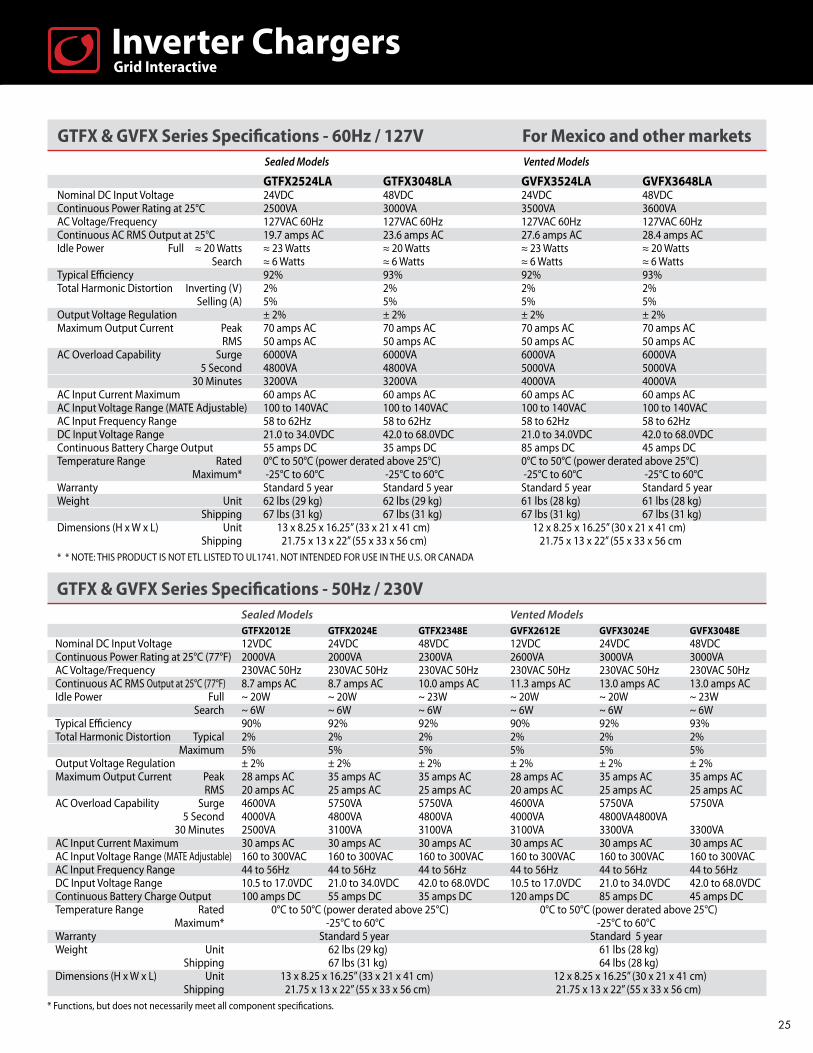
GTFX & GVFX Series Specifications - 60Hz / 127V For Mexico and other markets Sealed Models Vented Models
GTFX2524LA GTFX3048LA GVFX3524LA GVFX3648LANominal DC Input Voltage 24VDC 48VDC 24VDC 48VDCContinuous Power Rating at 25°C 2500VA 3000VA 3500VA 3600VAAC Voltage/Frequency 127VAC 60Hz 127VAC 60Hz 127VAC 60Hz 127VAC 60HzContinuous AC RMS Output at 25°C 19.7 amps AC 23.6 amps AC 27.6 amps AC 28.4 amps ACIdle Power Full ≈ 20 Watts ≈ 23 Watts ≈ 20 Watts ≈ 23 Watts ≈ 20 Watts Search ≈ 6 Watts ≈ 6 Watts ≈ 6 Watts ≈ 6 WattsTypical Efficiency 92% 93% 92% 93%Total Harmonic Distortion Inverting (V) 2% 2% 2% 2% Selling (A) 5% 5% 5% 5%Output Voltage Regulation ± 2% ± 2% ± 2% ± 2%Maximum Output Current Peak 70 amps AC 70 amps AC 70 amps AC 70 amps AC RMS 50 amps AC 50 amps AC 50 amps AC 50 amps ACAC Overload Capability Surge 6000VA 6000VA 6000VA 6000VA 5 Second 4800VA 4800VA 5000VA 5000VA 30 Minutes 3200VA 3200VA 4000VA 4000VAAC Input Current Maximum 60 amps AC 60 amps AC 60 amps AC 60 amps ACAC Input Voltage Range (MATE Adjustable) 100 to 140VAC 100 to 140VAC 100 to 140VAC 100 to 140VACAC Input Frequency Range 58 to 62Hz 58 to 62Hz 58 to 62Hz 58 to 62HzDC Input Voltage Range 21.0 to 34.0VDC 42.0 to 68.0VDC 21.0 to 34.0VDC 42.0 to 68.0VDCContinuous Battery Charge Output 55 amps DC 35 amps DC 85 amps DC 45 amps DCTemperature Range Rated 0°C to 50°C (power derated above 25°C) 0°C to 50°C (power derated above 25°C) Maximum* -25°C to 60°C -25°C to 60°C -25°C to 60°C -25°C to 60°CWarranty Standard 5 year Standard 5 year Standard 5 year Standard 5 yearWeight Unit 62 lbs (29 kg) 62 lbs (29 kg) 61 lbs (28 kg) 61 lbs (28 kg) Shipping 67 lbs (31 kg) 67 lbs (31 kg) 67 lbs (31 kg) 67 lbs (31 kg)Dimensions (H x W x L) Unit 13 x 8.25 x 16.25” (33 x 21 x 41 cm) 12 x 8.25 x 16.25” (30 x 21 x 41 cm) Shipping 21.75 x 13 x 22” (55 x 33 x 56 cm) 21.75 x 13 x 22” (55 x 33 x 56 cm * * NOTE: THIS PRODUCT IS NOT ETL LISTED TO UL1741. NOT INTENDED FOR USE IN THE U.S. OR CANADA
GTFX & GVFX Series Specifications - 50Hz / 230V Sealed Models Vented Models GTFX2012E GTFX2024E GTFX2348E GVFX2612E GVFX3024E GVFX3048E Nominal DC Input Voltage 12VDC 24VDC 48VDC 12VDC 24VDC 48VDC Continuous Power Rating at 25°C (77°F) 2000VA 2000VA 2300VA 2600VA 3000VA 3000VA AC Voltage/Frequency 230VAC 50Hz 230VAC 50Hz 230VAC 50Hz 230VAC 50Hz 230VAC 50Hz 230VAC 50Hz Continuous AC RMS Output at 25°C (77°F) 8.7 amps AC 8.7 amps AC 10.0 amps AC 11.3 amps AC 13.0 amps AC 13.0 amps AC Idle Power Full ~ 20W ~ 20W ~ 23W ~ 20W ~ 20W ~ 23W Search ~ 6W ~ 6W ~ 6W ~ 6W ~ 6W ~ 6W Typical Efficiency 90% 92% 92% 90% 92% 93% Total Harmonic Distortion Typical 2% 2% 2% 2% 2% 2% Maximum 5% 5% 5% 5% 5% 5% Output Voltage Regulation ± 2% ± 2% ± 2% ± 2% ± 2% ± 2% Maximum Output Current Peak 28 amps AC 35 amps AC 35 amps AC 28 amps AC 35 amps AC 35 amps AC RMS 20 amps AC 25 amps AC 25 amps AC 20 amps AC 25 amps AC 25 amps AC AC Overload Capability Surge 4600VA 5750VA 5750VA 4600VA 5750VA 5750VA 5 Second 4000VA 4800VA 4800VA 4000VA 4800VA 4800VA 30 Minutes 2500VA 3100VA 3100VA 3100VA 3300VA 3300VA AC Input Current Maximum 30 amps AC 30 amps AC 30 amps AC 30 amps AC 30 amps AC 30 amps AC AC Input Voltage Range (MATE Adjustable) 160 to 300VAC 160 to 300VAC 160 to 300VAC 160 to 300VAC 160 to 300VAC 160 to 300VAC AC Input Frequency Range 44 to 56Hz 44 to 56Hz 44 to 56Hz 44 to 56Hz 44 to 56Hz 44 to 56Hz DC Input Voltage Range 10.5 to 17.0VDC 21.0 to 34.0VDC 42.0 to 68.0VDC 10.5 to 17.0VDC 21.0 to 34.0VDC 42.0 to 68.0VDC Continuous Battery Charge Output 100 amps DC 55 amps DC 35 amps DC 120 amps DC 85 amps DC 45 amps DC Temperature Range Rated 0°C to 50°C (power derated above 25°C) 0°C to 50°C (power derated above 25°C) Maximum* -25°C to 60°C -25°C to 60°C Warranty Standard 5 year Standard 5 year Weight Unit 62 lbs (29 kg) 61 lbs (28 kg) Shipping 67 lbs (31 kg) 64 lbs (28 kg) Dimensions (H x W x L) Unit 13 x 8.25 x 16.25” (33 x 21 x 41 cm) 12 x 8.25 x 16.25” (30 x 21 x 41 cm) Shipping 21.75 x 13 x 22” (55 x 33 x 56 cm) 21.75 x 13 x 22” (55 x 33 x 56 cm) * Functions, but does not necessarily meet all component specifications.
Grid InteractiveInverter Chargers
25

M-Series mobileSpecial Application Models
M-Series Mobile/Marine SeriesEngineered for the unique demands of mobile and marine applications, M-Series inverter/ chargers have all of OutBack’s hallmark features and performance including modular expand-ability and the integration of inverter, battery charger and AC transfer switch into a single hardened die-cast aluminum chassis.
Coming to a military theater near youExperimental Forward Operating Base renewable energy system, Fort IrwinNational Training Center, California, as featured in the film Carbon Nation
With a appetite for over 300,000 barrels of oil daily, the United States Department of Defense is one of the largest single users of fossil fuel on the globe. It is also one of the most dedicated when it comes to reducing its dependency on oil. The reasons are not only green, but pragmatic: conveys required to transport fuel to remote, power-hungry Forward Operating Bases (FOB’s) are extremely vulnerable and a strategic liability. Generating power on-site reduces that risk, saving cost and lives.
In the 2010 film Carbon Nation, retired U.S. Army Colonel and “Green Hawk” movement founder Daniel Nolan demonstrates an innovation in field structures capable of reducing HVAC needs in desert condi-tions to about 1/6th that of conventional shelters, which as a result can be entirely run by PV and wind turbines. He’s making his point about the need to reduce the military’s dependency on oil in front of the OutBack FLEXware™ system powering the installation in which he’s standing.
The M-Series adds corrosion-resistant internal components
and a weather-resistant sealed chassis design to enable it to
better withstand the element.
Other features include power factor-corrected battery charging to get the most out of a shore cord and generator while maximizing battery life and performance and an ultra-fast AC transfer switch with neutral/ground switching for mobile applications to seamlessly transfer shore cord current without dropping loads. OutBack’s true sinewave AC power is ideal for running sensitive onboard electronics with minimal RF interference, while its industry-leading surge capability starts heavy loads such as air conditioning.
26
CLAYWAY MEDIA PRESENTS A PETER BYCK FILM “CARBON NATION” EXECUTIVE PRODUCERS PAULA CROWN, GIGI PRITZKER, NICK PRITZKER, PEGGY & HENRY SHARPE & THE LEMELSON FOUNDATIONGRAPHICS BY MFACTOR, INC. ANIMATION BY SIX POINT HARNESS AFTER EFFECTS ARTIST ANDREW FINK SOUND DESIGN BY ROBERT HAWES/NEPTUNES BROILER COMPOSER FLEXI P ORCHESTRATOR ROBERT HAWES
ASSOCIATE PRODUCERS MICHAEL COCHRAN, GILL HOLLAND, JIM SLAMA, GUETA MEZZETTI, MICHAEL LEIFER, PATRICIA JONES BLESSMAN & NICK STREET PRODUCED BY PETER BYCK, CRAIG SIEBEN, KAREN WEIGERT, ARTEMIS JOUKOWSKY & CHRISNA VAN ZYLNARRATION BY BILL KURTIS WRITEN BY PETER BYCK, ERIC DRISCOLL, MATT WEINHOLD & KAREN WEIGERT EDITED BY ERIC DRISCOLL & PETER BYCK DIRECTED BY PETER BYCK
carbonnationmovie.com© 2011 Clayway Media
carbo2n nationa documentary by peter byck
a climate change solutions movie[that doesn’t even care if you believe in climate change]
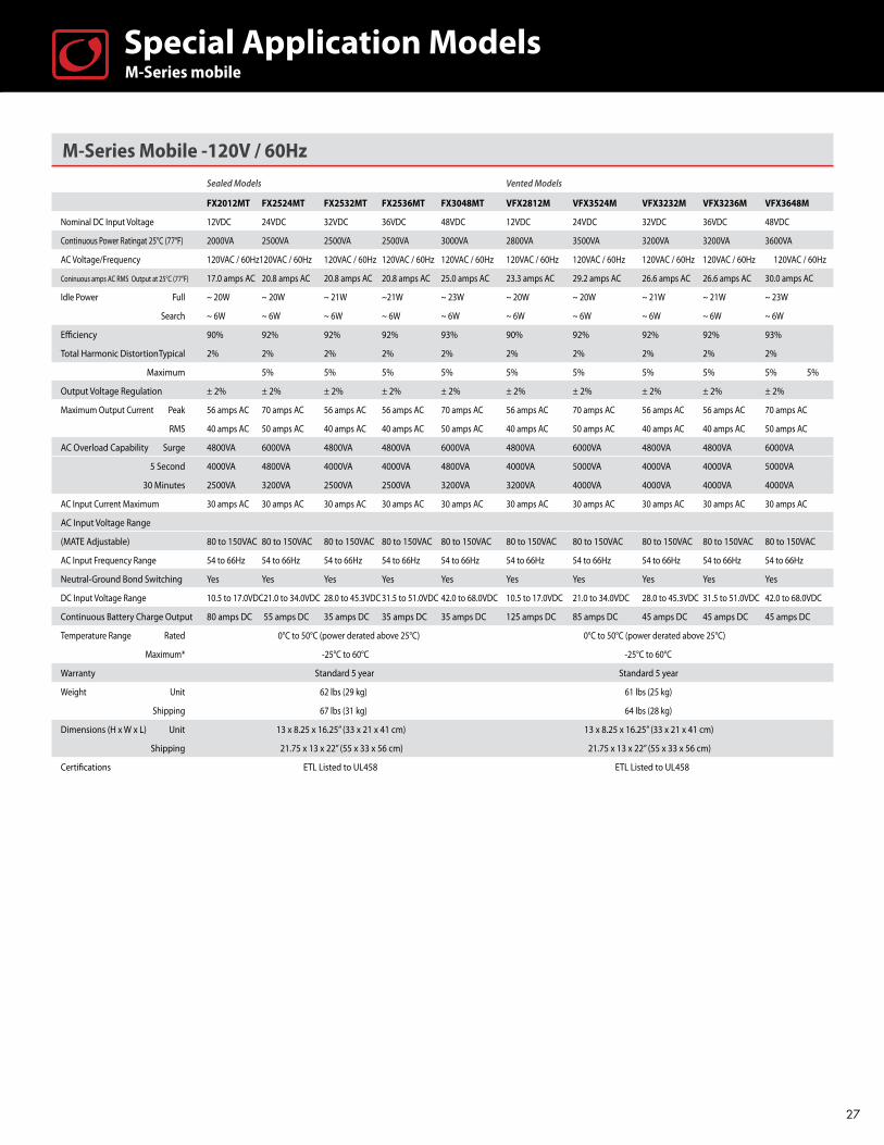
M-Series Mobile -120V / 60Hz
Sealed Models Vented Models
FX2012MT FX2524MT FX2532MT FX2536MT FX3048MT VFX2812M VFX3524M VFX3232M VFX3236M VFX3648M
Nominal DC Input Voltage 12VDC 24VDC 32VDC 36VDC 48VDC 12VDC 24VDC 32VDC 36VDC 48VDC
Continuous Power Ratingat 25°C (77°F) 2000VA 2500VA 2500VA 2500VA 3000VA 2800VA 3500VA 3200VA 3200VA 3600VA
AC Voltage/Frequency 120VAC / 60Hz120VAC / 60Hz 120VAC / 60Hz 120VAC / 60Hz 120VAC / 60Hz 120VAC / 60Hz 120VAC / 60Hz 120VAC / 60Hz 120VAC / 60Hz 120VAC / 60Hz
Coninuous amps AC RMS Output at 25°C (77°F) 17.0 amps AC 20.8 amps AC 20.8 amps AC 20.8 amps AC 25.0 amps AC 23.3 amps AC 29.2 amps AC 26.6 amps AC 26.6 amps AC 30.0 amps AC
Idle Power Full ~ 20W ~ 20W ~ 21W ~21W ~ 23W ~ 20W ~ 20W ~ 21W ~ 21W ~ 23W
Search ~ 6W ~ 6W ~ 6W ~ 6W ~ 6W ~ 6W ~ 6W ~ 6W ~ 6W ~ 6W
Efficiency 90% 92% 92% 92% 93% 90% 92% 92% 92% 93%
Total Harmonic Distortion Typical 2% 2% 2% 2% 2% 2% 2% 2% 2% 2%
Maximum 5% 5% 5% 5% 5% 5% 5% 5% 5% 5%
Output Voltage Regulation ± 2% ± 2% ± 2% ± 2% ± 2% ± 2% ± 2% ± 2% ± 2% ± 2%
Maximum Output Current Peak 56 amps AC 70 amps AC 56 amps AC 56 amps AC 70 amps AC 56 amps AC 70 amps AC 56 amps AC 56 amps AC 70 amps AC
RMS 40 amps AC 50 amps AC 40 amps AC 40 amps AC 50 amps AC 40 amps AC 50 amps AC 40 amps AC 40 amps AC 50 amps AC
AC Overload Capability Surge 4800VA 6000VA 4800VA 4800VA 6000VA 4800VA 6000VA 4800VA 4800VA 6000VA
5 Second 4000VA 4800VA 4000VA 4000VA 4800VA 4000VA 5000VA 4000VA 4000VA 5000VA
30 Minutes 2500VA 3200VA 2500VA 2500VA 3200VA 3200VA 4000VA 4000VA 4000VA 4000VA
AC Input Current Maximum 30 amps AC 30 amps AC 30 amps AC 30 amps AC 30 amps AC 30 amps AC 30 amps AC 30 amps AC 30 amps AC 30 amps AC
AC Input Voltage Range
(MATE Adjustable) 80 to 150VAC 80 to 150VAC 80 to 150VAC 80 to 150VAC 80 to 150VAC 80 to 150VAC 80 to 150VAC 80 to 150VAC 80 to 150VAC 80 to 150VAC
AC Input Frequency Range 54 to 66Hz 54 to 66Hz 54 to 66Hz 54 to 66Hz 54 to 66Hz 54 to 66Hz 54 to 66Hz 54 to 66Hz 54 to 66Hz 54 to 66Hz
Neutral-Ground Bond Switching Yes Yes Yes Yes Yes Yes Yes Yes Yes Yes
DC Input Voltage Range 10.5 to 17.0VDC21.0 to 34.0VDC 28.0 to 45.3VDC 31.5 to 51.0VDC 42.0 to 68.0VDC 10.5 to 17.0VDC 21.0 to 34.0VDC 28.0 to 45.3VDC 31.5 to 51.0VDC 42.0 to 68.0VDC
Continuous Battery Charge Output 80 amps DC 55 amps DC 35 amps DC 35 amps DC 35 amps DC 125 amps DC 85 amps DC 45 amps DC 45 amps DC 45 amps DC
Temperature Range Rated 0°C to 50°C (power derated above 25°C) 0°C to 50°C (power derated above 25°C)
Maximum* -25°C to 60°C -25°C to 60°C
Warranty Standard 5 year Standard 5 year
Weight Unit 62 lbs (29 kg) 61 lbs (25 kg)
Shipping 67 lbs (31 kg) 64 lbs (28 kg)
Dimensions (H x W x L) Unit 13 x 8.25 x 16.25” (33 x 21 x 41 cm) 13 x 8.25 x 16.25” (33 x 21 x 41 cm)
Shipping 21.75 x 13 x 22” (55 x 33 x 56 cm) 21.75 x 13 x 22” (55 x 33 x 56 cm)
Certifications ETL Listed to UL458 ETL Listed to UL458
M-Series mobileSpecial Application Models
27

M-Series Mobile - 230V / 50Hz
Sealed Models Vented Models
FX2012EMT FX2024EMT FX2348EMT VFX2612EM VFX3024EM VFX3048EM
Nominal DC Input Voltage 12VDC 24VDC 48VDC 12VDC 24VDC 48VDC
Continuous Power Rating at 25°C (77°F) 2000VA 2000VA 2300VA 2600VA 3000VA 3000VA
AC Voltage/Frequency 230VAC / 50Hz 230VAC / 50Hz 230VAC / 50Hz 230VAC / 50Hz 230VAC / 50Hz 230VAC / 50Hz
Continuous AC RMS Output at 25°C (77°F) 8.7 amps AC 8.7 amps AC 10.0 amps AC 11.3 amps AC 13.0 amps AC 13.0 amps AC
Idle Power Full ~ 20W ~ 20W ~ 23W ~ 20W ~ 20W ~ 23W
Search ~ 6W ~ 6W ~ 6W ~ 6W ~ 6W ~ 6W
Typical Efficiency 90% 92% 93% 90% 92% 93%
Total Harmonic Distortion Typical 2% 2% 2% 2% 2% 2%
Maximum 5% 5% 5% 5% 5% 5%
Output Voltage Regulation ± 2% ± 2% ± 2% ± 2% ± 2% ± 2%
Maximum Output Current Peak 28 amps AC 35 amps AC 35 amps AC 28 amps AC 35 amps AC 35 amps AC
RMS 20 amps AC 25 amps AC 25 amps AC 20 amps AC 25 amps AC 25 amps AC
AC Overload Capability Surge 4600VA 5750VA 5750VA 4600VA 5750VA 5750VA
5 Seconds 4000VA 4800VA 4800VA 4000VA 4800VA 4800VA
30 Minutes 2500VA 3100VA 3100VA 3100VA 3300VA 3300VA
AC Input Current Maximum 30 amps AC 30 amps AC 30 amps AC 30 amps AC 30 amps AC 30 amps AC
AC Input Voltage Range (MATE Adjustable) 160 to 300VAC 160 to 300VAC 160 to 300VAC 160 to 300VAC 160 to 300VAC 160 to 300VAC
AC Input Frequency Range 44 to 56Hz 44 to 56Hz 44 to 56Hz 44 to 56Hz 44 to 56Hz 44 to 56Hz
Neutral-Ground Bond Switching Yes Yes Yes Yes Yes Yes
DC Input Voltage Range 10.5 to 17.0VDC 21.0 to 34.0VDC 42.0 to 68.0VDC 10.5 to 17.0VDC 21.0 to 34.0VDC 42.0 to 68.0VDC
Continuous Battery Charger Output 100 amps DC 55 amps DC 35 amps DC 120 amps DC 85 amps DC 45 amps DC
Temperature Range Rated 0°C to 50°C (power derated above 25°C) 0°C to 50°C (power derated above 25°C)
Maximum* -25°C to 60°C -25°C to 60°C
Warranty Standard 5 year Standard 5 year
Weight Unit 62 lbs (29 kg) 61 lbs (28 kg)
Shipping 67 lbs (31 kg) 67 lbs (31 kg)
Dimensions H x W x L 13 x 8.25 x 16.25” (33 x 21 x 41 cm) 12 x 8.25 x 16.25” (30 x 21 x 41 cm)
Shipping 21.75 x 13 x 22” (55 x 33 x 56 cm) 21.75 x 13 x 22” (55 x 33 x 56 cm) * Functions, but does not necessarily meet all component specifications.
M-Series mobileSpecial Application Models
28

Extreme SeriesSpecial Application Models
Extreme SeriesThe OutBack Extreme Series Inverter/Charger is all that its name implies. Built from exceptionally rugged components not available in regular commercial “off-the-shelf inverter/chargers, the water-resistant Extreme Series inverters are designed to survive harsh environmental conditions including shock and vibration.
Extreme Series inverter/chargers feature intelligent
battery charging and an integrated AC transfer switch
with automatic neutral-ground switching for mobile
applications.
“Mount anywhere” design and silent operation along with low-distortion pure sinewave power output make them ideal for mobile electrical needs, and their ample surge capability can start multiple heavy loads simultaneously. Integrated building block architecture allows expanding a system from 2 to 36 kW, and user-defined settings allow systems operation at 120 VAC, 120/240 VAC or 120Y208 VAC three-phase by stacking multiple Extreme inverter/chargers together.
29
When “built like a tank” means more than a cliche´M-113 Armored Personnel Carrier, various United States and International military applications.
According to the Army, the M113 “helped to revolutionize mobile military operations” as a fighting platform. That’s an understatement. The M113 can do everything: launch missiles or mortar shells at ground targets and fire a Vulcan M741 20-mm cannon at air targets,
transport soldiers in combat, serve as a field command post, and either roll, swim or get air-dropped to any-place it needs to be.
As might be expected, the instrumentation, navigation, surveillance, computing and communications electron-ics on-board such a military marvel are mission-critical, and demand an on-board power source that’s actually build better than the tank on which it’s riding. That’s why OutBack Extreme-series inverter/chargers serve with not just the M113, but also the Unites States Marine Corps’ MRAP Cougar, the United Kingdom’s Panther, and a host of other modern fighting vehicles.
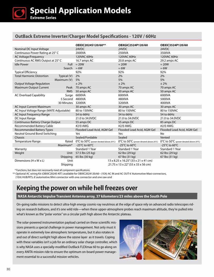
OutBack Extreme Inverter/Charger Model Specifications - 120V / 60Hz
OBXIC2024S120/60** OBXGIC2524P120/60 OBXIC3524P120/60 Nominal DC Input Voltage 24VDC 24VDC 24VDC Continuous Power Rating at 25° C 2000VA 2500VA 3500VA AC Voltage/Frequency 120VAC 60Hz 120VAC 60Hz 120VAC 60Hz Continuous AC RMS Output at 25° C 16.7 amps AC 20.8 amps AC 29.2 amps AC Idle Power Full ≈ 20W ≈ 20W ≈ 20W Search ≈ 6W ≈ 6W ≈ 6W Typical Efficiency 92% 92% 92% Total Harmonic Distortion Typical (V) 2% 2% 2% Maximum (V) 5% 5% 5% Output Voltage Regulation ± 2% ± 2% ± 2% Maximum Output Current Peak 70 amps AC 70 amps AC 70 amps AC RMS 50 amps AC 50 amps AC 50 amps AC AC Overload Capability Surge 6000VA 6000VA 6000VA 5 Second 4800VA 4800VA 5000VA 30 Minutes 3200VA 3200VA 4000VA AC Input Current Maximum 30 amps AC 30 amps AC 30 amps AC AC Input Voltage Range (MATE Adjustable) 80 to 150VAC 80 to 150VAC 80 to 150VAC AC Input Frequency Range 54 to 66Hz 54 to 66Hz 54 to 66Hz DC Input Range 21.0 to 34.0VDC 21.0 to 34.0VDC 21.0 to 34.0VDC Continuous Battery Charge Output 55 amps DC 55 amps DC 85 amps DC Recommended Battery Cable #2/0 AWG #2/0 AWG #2/0 AWG Recommended Battery Types Flooded Lead Acid, AGM Gel Flooded Lead Acid, AGM Gel Flooded Lead Acid, AGM Gel Neutral Ground Bond Switching Yes Yes No Chassis Sealed/Fordable Sealed Vented Temperature Range Rated 0°C to 50°C (power derated above 25°C) 0°C to 50°C (power derated above 25°C) 0°C to 50°C (power derated above 25°C)
Maximum* -25°C to 60°C -25°C to 60°C -25°C to 60°C Warranty Standard 1 Year Standard 1 Year Standard 1 Year Weight Unit 57.5 lbs (25 kg) 62 lbs (29 kg) 62 lbs (29 kg) Shipping 65 lbs (30 kg) 67 lbs (31 kg) 67 lbs (31 kg) Dimensions (H x W x L) Unit 13 x 8.25 x 16.25” (33 x 21 x 41 cm) Shipping 21.75 x 13 x 22” (55 x 33 x 56 cm)
* Functions, but does not necessarily meet all component specifications.** Optional AC wiring Kit (OBXIC2024S-KIT) available for OBXIC2024120/60 - (1EA) AC IN and AC OUT 6’ Automotive Maxi-connectors, (1EA) HUB/RTS, 6’ automotive Mini-connector with one connector and one raw end
Extreme SeriesSpecial Application Models
Keeping the power on while hell freezes overNASA Antarctic Impulse Transient Antenna array, 37 kilometers/23 miles above the South Pole
On-going radio missions to detect ultra-high energy cosmic-ray neutrinos at the edge of space rely on advanced radio telescopes rid-ing on research balloons, and it’s one wild ride—when these upper-atmosphere probes reach maximum altitude, they’re pulled into what’s known as the “polar vortex” on a circular path high above the Antarctic plateau.
The solar-powered instrumentation payload carried on these scientific mis-sions presents a special challenge in power management. Not only must it operate in extremely low atmospheric temperatures, but it also rotates in and out of direct sunlight high above the ozone layer as it travels. Coping with these variables isn’t a job for an ordinary solar charge controller, which is why NASA uses a specially-modified OutBack FLEXmax 60 to go along on every ANITA mission ride to ensure the optimum on-board power manage-ment essential to a successful mission vehicles.
30

OutBack Extreme Inverter/Charger Model Specifications - 230V / 50Hz
OBXIC2024P230/50 Nominal DC Input Voltage 24VDC
Continuous Power Rating at 25°C 2000VAAC Voltage/Frequency 230VAC 50Hz
Continuous AC RMS Output at 25°C 8.7 amps ACIdle Power Full ≈ 20W Search ≈ 6W
Typical Efficiency 92%Total Harmonic Distortion Typical (V) 2% Maximum (V) 5%
Output Voltage Regulation ± 2%Maximum Output Current Peak 35 amps AC RMS 25 amps AC
AC Overload Capability Surge 5750VA 5 Second 4800VA 30 Minutes 3100VA
AC Input Current Maximum 30 amps AC AC Input Voltage Range (MATE Adjustable) 160 to 300VAC
AC Input Frequency Range 44 to 56Hz DC Input Range 21.0 to 34.0VDC
Continuous Battery Charge Output 55 amps DC Recommended Battery Cable #2/0 AWG
Recommended Battery Types Flooded Lead Acid, AGM Gel Neutral Ground Bond Switching No
Chassis Sealed Temperature Range Rated 0°C to 50°C (power derated above 25°C) Maximum* -25°C to 60°C
Warranty Standard 1 year Weight Unit 62 lbs (29 kg) Shipping 67 lbs (31 kg)
Dimensions (H x W x L) Unit 13 x 8.25 x 16.25” (33 x 21 x 41 cm) Shipping 21.75 x 13 x 22” (55 x 33 x 56 cm)
* Functions, but does not necessarily meet all component specifications.
Extreme SeriesSpecial Application Models
A cataclysm with a viewUS Cellular base transceiver station (BTS) overlooking Mount St. Helens, Washington
More than 4,000 feet up and right next to Mount St. Helens, the site of the most violent geological event in North American recorded history, it’s safe to say that the US Cellular BTS installation location is way beyond typical even for this typically-remote category. It is also an exceptionally challenging one for using renewable energy. Not only are there
extremes of temperature to contend with, but the PV array must be mounted high enough to prevent it being buried by snow.
Solar power is essential to operating this station since propane fuel to run the generator must be brought in by snow-cat during the winter. And the station is essential in providing communications to the Forest Service personnel, hikers, researchers, and others frequenting this famous location. The on-site renewable energy system uses twin OutBack VFX-series inverters and four FLEXmax charge controllers, which dependably power this remote, autonomous link to the outside world.
31
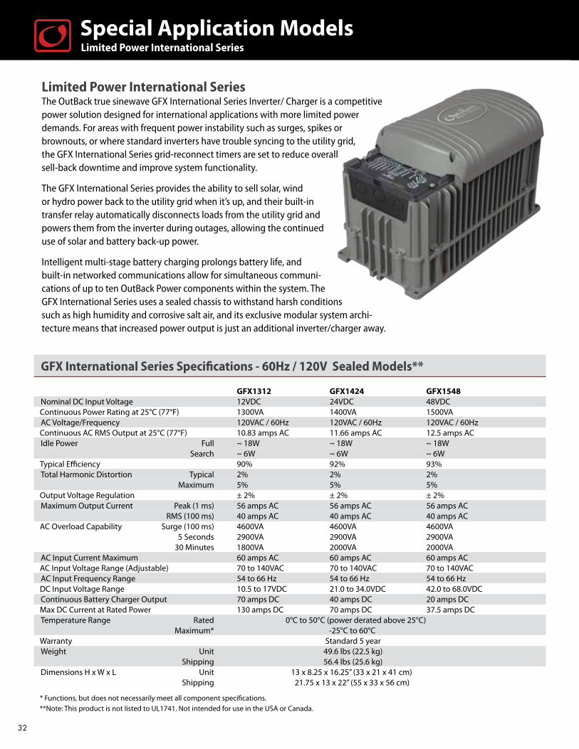
Limited Power International Series The OutBack true sinewave GFX International Series Inverter/ Charger is a competitive power solution designed for international applications with more limited power demands. For areas with frequent power instability such as surges, spikes or brownouts, or where standard inverters have trouble syncing to the utility grid, the GFX International Series grid-reconnect timers are set to reduce overall sell-back downtime and improve system functionality.
The GFX International Series provides the ability to sell solar, wind or hydro power back to the utility grid when it’s up, and their built-in transfer relay automatically disconnects loads from the utility grid and powers them from the inverter during outages, allowing the continued use of solar and battery back-up power.
Intelligent multi-stage battery charging prolongs battery life, and built-in networked communications allow for simultaneous communi-cations of up to ten OutBack Power components within the system. The GFX International Series uses a sealed chassis to withstand harsh conditions such as high humidity and corrosive salt air, and its exclusive modular system archi-tecture means that increased power output is just an additional inverter/charger away.
GFX International Series Specifications - 60Hz / 120V Sealed Models**
GFX1312 GFX1424 GFX1548Nominal DC Input Voltage 12VDC 24VDC 48VDC
Continuous Power Rating at 25°C (77°F) 1300VA 1400VA 1500VAAC Voltage/Frequency 120VAC / 60Hz 120VAC / 60Hz 120VAC / 60Hz
Continuous AC RMS Output at 25°C (77°F) 10.83 amps AC 11.66 amps AC 12.5 amps ACIdle Power Full ~ 18W ~ 18W ~ 18W Search ~ 6W ~ 6W ~ 6W
Typical Efficiency 90% 92% 93%Total Harmonic Distortion Typical 2% 2% 2% Maximum 5% 5% 5%
Output Voltage Regulation ± 2% ± 2% ± 2%Maximum Output Current Peak (1 ms) 56 amps AC 56 amps AC 56 amps AC RMS (100 ms) 40 amps AC 40 amps AC 40 amps AC
AC Overload Capability Surge (100 ms) 4600VA 4600VA 4600VA 5 Seconds 2900VA 2900VA 2900VA 30 Minutes 1800VA 2000VA 2000VA
AC Input Current Maximum 60 amps AC 60 amps AC 60 amps AC AC Input Voltage Range (Adjustable) 70 to 140VAC 70 to 140VAC 70 to 140VAC
AC Input Frequency Range 54 to 66 Hz 54 to 66 Hz 54 to 66 Hz DC Input Voltage Range 10.5 to 17VDC 21.0 to 34.0VDC 42.0 to 68.0VDC
Continuous Battery Charger Output 70 amps DC 40 amps DC 20 amps DC Max DC Current at Rated Power 130 amps DC 70 amps DC 37.5 amps DC
Temperature Range Rated 0°C to 50°C (power derated above 25°C) Maximum* -25°C to 60°C
Warranty Standard 5 year Weight Unit 49.6 lbs (22.5 kg) Shipping 56.4 lbs (25.6 kg) Dimensions H x W x L Unit 13 x 8.25 x 16.25” (33 x 21 x 41 cm)
Shipping 21.75 x 13 x 22” (55 x 33 x 56 cm) * Functions, but does not necessarily meet all component specifications. **Note: This product is not listed to UL1741. Not intended for use in the USA or Canada.
Limited Power International SeriesSpecial Application Models
32
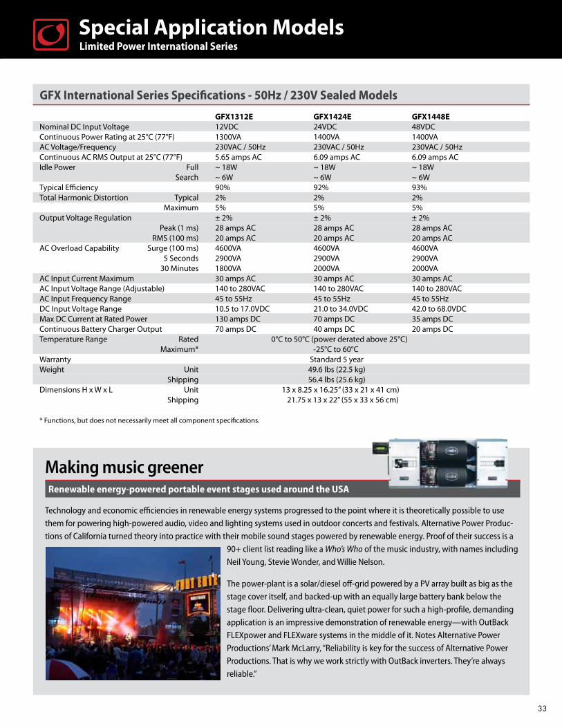
GFX International Series Specifications - 50Hz / 230V Sealed Models
GFX1312E GFX1424E GFX1448ENominal DC Input Voltage 12VDC 24VDC 48VDCContinuous Power Rating at 25°C (77°F) 1300VA 1400VA 1400VA AC Voltage/Frequency 230VAC / 50Hz 230VAC / 50Hz 230VAC / 50Hz Continuous AC RMS Output at 25°C (77°F) 5.65 amps AC 6.09 amps AC 6.09 amps ACIdle Power Full ~ 18W ~ 18W ~ 18W Search ~ 6W ~ 6W ~ 6WTypical Efficiency 90% 92% 93%Total Harmonic Distortion Typical 2% 2% 2% Maximum 5% 5% 5%Output Voltage Regulation ± 2% ± 2% ± 2% Peak (1 ms) 28 amps AC 28 amps AC 28 amps AC RMS (100 ms) 20 amps AC 20 amps AC 20 amps ACAC Overload Capability Surge (100 ms) 4600VA 4600VA 4600VA 5 Seconds 2900VA 2900VA 2900VA 30 Minutes 1800VA 2000VA 2000VAAC Input Current Maximum 30 amps AC 30 amps AC 30 amps AC AC Input Voltage Range (Adjustable) 140 to 280VAC 140 to 280VAC 140 to 280VAC AC Input Frequency Range 45 to 55Hz 45 to 55Hz 45 to 55Hz DC Input Voltage Range 10.5 to 17.0VDC 21.0 to 34.0VDC 42.0 to 68.0VDCMax DC Current at Rated Power 130 amps DC 70 amps DC 35 amps DCContinuous Battery Charger Output 70 amps DC 40 amps DC 20 amps DCTemperature Range Rated 0°C to 50°C (power derated above 25°C) Maximum* -25°C to 60°C Warranty Standard 5 year Weight Unit 49.6 lbs (22.5 kg) Shipping 56.4 lbs (25.6 kg) Dimensions H x W x L Unit 13 x 8.25 x 16.25” (33 x 21 x 41 cm) Shipping 21.75 x 13 x 22” (55 x 33 x 56 cm) * Functions, but does not necessarily meet all component specifications.
Limited Power International SeriesSpecial Application Models
Making music greenerRenewable energy-powered portable event stages used around the USA
Technology and economic efficiencies in renewable energy systems progressed to the point where it is theoretically possible to use them for powering high-powered audio, video and lighting systems used in outdoor concerts and festivals. Alternative Power Produc-tions of California turned theory into practice with their mobile sound stages powered by renewable energy. Proof of their success is a
90+ client list reading like a Who’s Who of the music industry, with names including Neil Young, Stevie Wonder, and Willie Nelson.
The power-plant is a solar/diesel off-grid powered by a PV array built as big as the stage cover itself, and backed-up with an equally large battery bank below the stage floor. Delivering ultra-clean, quiet power for such a high-profile, demanding application is an impressive demonstration of renewable energy—with OutBack FLEXpower and FLEXware systems in the middle of it. Notes Alternative Power Productions’ Mark McLarry, “Reliability is key for the success of Alternative Power Productions. That is why we work strictly with OutBack inverters. They’re always reliable.”
33

FLEXmax™ Charge Controllers & AXS Port InterfaceA charge controller’s main job is to optimize a PV array’s output which can fluctuate based on shading and temperature variables found on the average roof. OutBack’s FLEXmax™ Controller is anything but average—so rugged and reliable that it’s used by NASA on solar arrays in high-altitude testing 20 miles over Antarctica.
FLEXmax Charge Controllers truly represent innovation in Maximum Power Point Tracking (MPPT) technology, which enables them to increase the yield from a solar photovoltaic (PV) array as much as 30% over conventional designs. At the industry’s first multi-voltage MPPT and a landmark design, OutBack’s FLEXmax series is the most copied controller on the market today. FLEXmax Controllers support a wide variety of system designs, battery chemistries, and integrate seamlessly in terms of system data management and programming.
The innovative FLEXmax MPPT software algorithm is both continuous and active, increasing photovoltaic array power yield up to 30% compared to non-MPPT controllers. Thanks to active cooling and intelligent thermal management cooling, both FLEXmax Charge Controllers can operate at their full maximum current rating, 60 amps or 80 amps respectively, in ambient temperatures as high as 104°F (40°C).
FLEXmax Charge Controllers incorporate the revolutionary features first developed by OutBack Power, including support for a wide range of nominal battery voltages and the ability to step-down a higher voltage solar array to recharge a lower voltage battery bank. A built in, backlit 80-character display shows the current status and logged system performance data for the last 128 days at the touch of a button. Integrated OutBack network communications capability allows FLEXmax Series Charge Controllers to be remotely programmed and monitored via a MATE system display and provides complete system integration.
FLEXmax 80 FLEXmax 60
maxTM 80Charge Controller
Saving money when the sun shines, saving much more when it’s notFlorida Solar Energy Center SunSmart E-Shelter program
With the distinction of ranking first in the number of hurricane strikes in the U.S.A., the State of Florida takes emergency prepared-ness seriously and sets high standards in disaster infrastructure through a network of Enhanced Hurricane Protection Area (EHPAs) public shelters designed to provide life-saving protection from storms for up to eight hours. To maximize return on this investment, the Florida Solar Energy Center took the innovative approach of “triple purpose” shelters planned for 90 schools throughout the state, each designed to also provide energy savings through ongoing solar power generation as well as serve as energy education classrooms for students in the selected schools.
PV system designers met the challenge of delivering both grid-tied savings during normal times and off-grid independence during emergencies with 3-phase arrays of OutBack GVFX-series inverter/chargers powering the E-Shelters in the school program. Public schools save money on utility bills, students learn about energy technology, and communities have essential power during emergen-cies—all with one versatile system.
34

FLEXmax 80 - FM80-150VDC FLEXmax 60 - FM60-150VDC
Nominal Battery Voltages 12, 24, 36, 48, or 60VDC (Single model - selectable via field programming at start-up) Maximum Output Current 80A @ 104ºF (40ºC) with adjustable current limit 60A @ 104ºF (40ºC) with adjustable current limitNEC Recommended Solar Array STC Nameplate 12VDC systems 1000W / 24VDC systems 2000W 12VDC systems 750W / 24VDC systems 1500W 48VDC systems 4000W / 60VDC Systems 5000W 48VDC systems 3000W / 60VDC Systems 3750WPV Open Circuit Voltage (VOC) 150VDC absolute maximum coldest conditions / 145VDC start-up and operating maximum Standby Power Consumption Less than 1W typical Less than 1W typicalPower Conversion Efficiency 97.5% @ 80A in a 48VDC System - Typical 98.1% @ 60A in at 48VDC System voltage - TypicalCharging Regulation Five Stages: Bulk, Absorption, Float, Silent and Equalization Voltage Regulation Set points 10 to 60VDC user adjustable with password protection Equalization Charging Programmable Voltage Setpoint and Duration - Automatic Termination when completed Battery Temperature Compensation Automatic with optional RTS installed / 5.0 mV per °C per 2V battery cell Voltage Step-Down Capability Can charge a lower voltage battery from a higher voltage PV array - max 150VDC input Programmable Auxiliary Control Output 12VDC output signal which can be programmed for different control applications (maximum of 0.2 amps DC) Status Display 3.1” (8 cm) backlit LCD screen - 4 lines with 80 alphanumeric characters total
Remote Display and Controller Optional MATE3, MATE or MATE2 with RS232 Serial Communications Port
Network Cabling Proprietary network system using RJ 45 Modular Connectors with CAT5 Cable (8 wires)
Data Logging Last 128 days of Operation - Amp Hours, Watt Hours, Time in Float, Peak Watts, Amps,
Solar Array Voltage, Max Battery Voltage Min Battery Voltage and Absorb for each day along with total Accumulated Amp Hours, and kW Hours of production Hydro Turbine Applications Consult factory for approved turbines
Positive Ground Application Requires dual pole breakers for switching both positive and negative
conductors on both solar array and battery connections Operating Temperature Range -40ºC to 60ºC (power automatically derated above 40ºC) Environmental Rating Indoor Type 1 Conduit Knockouts One 1” (35mm) on the back; One1” (35mm) on the left side; Two 1” (35mm) on the bottom Warranty Standard 5 year / Available 10 year Weight Unit 12.20 lbs (5.56 kg) 11.65 lbs (5.3 kg) Shipping 15.5 lbs (7.03 kg) 14.90 lbs (6.7 kg) Dimensions Unit (H x W x DUnit16.25 x 5.75 x 4.5” (41.3 x 14.6 x 11.4 cm) 13.75 x 5.75 x 4.5” (35 x 14.6 x 11.4 cm) Shipping 21 x 10.5 x 10.5” (53 x 27 x 27 cm) 18 x 11 x 8” (46 x 28 x 21 cm) Options Remote Temperature Sensor (RTS), HUB4, HUB10, MATE, MATE 2, MATE3 Menu Languages English & Spanish Certifications ETL Listed to UL1741, CSA C22.2 No. 107.1
FLEXmax™ Specifications
Use appropriate wire size in accordance with NEC.
35
maxTM 80Charge Controller

AXS Port Modbus InterfaceTargeting industrial and commercial customers, the SunSpec-compliant AXS Port Modbus/TCP Interface provides advanced connectivity with OutBack FLEXmax™ Charge Controllers as well as other OutBack devices, enabling remote system status monitoring, command and control. Access an OutBack power system anywhere in the world via an Ethernet connection using Modbus Transmission Control Protocol (TCP) and communicate directly to a single device, or to multiple devices using OutBack’s HUB4 or HUB10 communications management components.
maxTM 80Charge Controller
AXS Port Specifications
Power Supplied by OutBack device
Status Indicators Seven LED indicators Clock On-board real-time clock with battery backup Internet Standards TCP/IP, DNS, SMTP, FTP, DHCP, NTP Ports HUB/Device RJ-45 Communications RJ-45 Temperature Sensor RJ-11Communication Protocol Modbus TCP to the SunSpec standard OutBack Device Interface OutBack Proprietary PC Interface 10/100 Ethernet Mounting DIN clip (provided) or surface mounting Environmental Rating Indoor Type 1 (IP 30) non-condensing Temperature Ranges AXS Port: -40°C to 75°C SD Card: -25°C to 75°C Weight Unit 0.5 lb (0.23 kg) Shipping 2.1 lb (0.95 kg)Dimensions - (H x W x D) Unit 1.29” x 3.5” x 4.99” (3.3 x 8.9 x 12.7 cm) Shipping 3.25” x 9” x 13.5” (19 x 22.9 x 34.3 cm)SD Card Size MicroSD Type 2 2 GB capacityOptions OutBack RTS
Certifications FCC Part 15, subpart B CE, RoHS, SunSpec
36

MATE3 The MATE3 System Display and Controller make it easier than ever to program and monitor a complete OutBack Power system. An intuitive user interface and integrated system configuration wizard make system setup and programming quick and seamless. The ability to set unique multi-level user passwords makes it possible to secure critical system settings from unintended changes while still allowing open access to necessary functions.
MATE3, MATE/MATE2 ControllersSystem Communications
Other features making system management simpler include an easy-to-read graphical backlit LCD display, improved tactile buttons, and a user programmable “favorite” key for immediate access to the most wanted features. An intuitive scroll wheel interface allows easy adjust-ment of system set points. Expandable SD card memory increases data logging capacity as well as making it easy to upgrade units in the field.
A built-in clock and calendar function enables timer-based programming of inverter and charger operation, which allows setting the system to work with time-of-day power rates or to limit a generator’s run time to a specific time period of the day or week. All settings are stored in permanent memory to eliminate the need to reprogram in the event of a system shutdown or battery replacement. The MATE3 supports web-server access via an intranet to allow monitoring of an OutBack system.
Cleaner energy for greener community developmentMini-grids for rural clinics and services in various communities, Lesotho, Africa
Funded by groups including the Gates Foundation, Clinton Foundation, Partners in Health, the Solar Electric Light Fund, and others, African solar projects aimed at transforming communities are locally-built and owned to ensure that they are replicable and remain sus-tainable. Each project flows from the needs and leadership of the community, which participates in all project phases including design, implementation, monitoring and evaluation. Reliable, sustainable and cost-effective solar energy remains the best choice to meet the electrical needs of rural clinics that are the front-line in the fight against diseases including malaria, tuberculosis, and AIDS. Villagers, both men and women, are trained to install, maintain and ultimately duplicate complete solar energy systems that will power the es-sential core of community services. This installation is one of many in Africa built around OutBack components. The modular FLEXware concept is well suited for these applications, with ease of installation and configuration that makes them ideal renewable system teach-ing platforms for training future community owner/operators to become self-sufficient in energy production.
Through the use of a single MATE3, multiple inverter/chargers, charge
controllers, and DC monitoring devices can be remotely monitored.
37

MATE
MATE2
MATE 3 Specifications
Display 4.0 x 1.2” full graphical display Quick System Access 5 system operation hot keys, 1 user programmable hot key Status Indicators Nine LED Status Indicators Navigational Controls 5 navigational keys Setpoint Adjustment Touch sensitive scroll wheel Communication Protocol Proprietary OutBack Communications Protocol Interconnection Cabling Standard CAT5 network cable with RJ45 modular jack - 6’ (2 m) included PC Computer Interface HTML system status dashboard over local intranet connection Field Update Capability Yes (includes Radian inverter and MATE3) Microprocessor 80 MHz 32 bit processor Setpoint and Data Memory 8Mb RAM/ 64Mb of flash RAM Clock / Calendar On-board real time clock with battery backup Operating Temperature Range 0°C to 50°C Environmental Rating Indoor Type 1 (IP 30) Maximum Cable Length 300’ (100 m) Warranty Standard 5 year Weight Unit 1.4 lbs (0.64 kg) Shipping 3.0 lbs (1.36 kg) Dimensions (H x W x L) Unit 7.5 x 7.1 x 1.5” (19 x 17.9 x 4.2 cm)
MATE & MATE2As complete management tools for OutBack Power systems, the MATE and MATE2 are packed full of features to make system management simple.
A single MATE can remotely manage and monitor multiple inverter/chargers, charge controllers and monitoring devices. The easy-to-read 3.1” (8 cm) LCD is backlit for dark operating conditions. Four soft keys allow easy context-based navigation of menus and functions. Two hot keys give immediate access to AC and inverter functions. A built-in clock and calendar function enables timer-based programming of inverter and charger operation, allowing the system to operate with time-of-day power rates or limit a generator’s run time to a specific time period of the day or week. All settings are stored in permanent memory to eliminate the need to reprogram in the event of a system shutdown or battery replacement.
The MATE and MATE2 include a RS232 port with DB9 jack for connection to the serial port of a PC computer. The MATE system display and controller is surface-mounted; MATE2 is flush-mountable in a wall cut-out.
MATE & MATE 2 Specifications
MATE Grey Surface-mount MATE_B Black Surface-mount MATE2 Black Flush Mount Interface Display 3.1” (8 cm) backlit LCD - four line, 80 alpha numeric characters Control Keypad 6 backlit silicone keys - dedicated inverter and AC input keys Status Indicators Two LED Status Indicators - AC input (yellow), inverting (green) Communication Protocol Proprietary OutBack Multi-drop using an OutBack HUB4 or HUB10 Interconnection Cabling Standard CAT5 network cable with RJ45 modular jack - 10’ (5 m) included PC Computer Interface RS232 opto-isolated DB9 jack 9600 baud serial communication Microprocessor 16 MHz low power consumption version Set point and Data Memory 32K non-volatile flash RAM Clock / Calendar On-board real time clock with battery backup Operating Temperature Range 0°C to 50°C Environmental Rating Indoor Type 1 (IP 30) Maximum Cable Length 1000’ (300 m) Warranty Standard 5 year Weight Shipping 1 lb (0.5 kg) Dimensions (H x W x L) Shipping 5.75 x 4.25 x 2” (15 x 11 x 5 cm)
MATE3, MATE/MATE2 ControllersSystem Communications
38

HUB Communications ManagerThe HUB system communications manager components form the backbone of a networked OutBack power conversion system. The OutBack HUB communicates stacking, load share and power save off/on signals. Interconnection cabling is standard Ethernet CAT5 with RJ45 modular jacks. Through a HUB, a system is completely coordinated and managed by the MATE system display/controller.
HUB4 HUB10
HUB10
Hub Communications Manager Specificatiions
HUB4 HUB10 Number of Ports 4 Plus MATE 10 Plus MATE Operating Temperature Range 0°C to 50°C 0°C to 50°C Warranty Standard 5 year Standard 5 year Weight Unit 1 lb (0.5 kg) 1 lb (0.5 kg) Shipping 3 lbs (1.4 kg) 3 lbs (1.4 kg) Dimensions (H x W x L) Unit 10.5 x 6.25 x 1.27” (27 x 16 x 3 cm) 10.5 x 6.25 x 1.27” (27 x 16 x 3 cm) Shipping 12 x 6 x 5” (31 x 15 x 13 cm) 12 x 6 x 5” (31 x 15 x 13 cm)
HUB4/10 Communications Management devicesSystem Communications
39

FLEXnet™ DCThe OutBack FLEXnet DC is the ultimate DC System monitoring device. Integrated networked communications capability makes valuable, usable data available from a system viewable on an OutBack MATE communications device (screens shown below), providing information on system health, performance and efficiency. FLEXnet DC provides real state-of-charge (S.O.C.) information about the life and state of a battery bank.
FLEXnet-DC Specifications
Battery Voltage Input Range 8.0 to 80.0VDCBattery Voltage Resolution 0.1VDCNumber of Current Channels One to Three (each can be a Source or Load)Current Range (each channel) -1000.0 amps to +1000.0 amps DCCurrent Resolution 0.1 amps DCState of Charge Display 0 to 100% (1% increments)Aux Relay Configuration SPST, Magnetic Latching RelayAux Relay Max Rating 5A @ 30VDCCurrent Shunt Type (order separately) 500A / 50mVDisplay Primary MATE, MATE2 or MATE3 Secondary Five LED Indicators on front of FLEXnet DCBattery AH Capacity Range 100 to 10,000 Amp HoursData Logging Memory Most recent 128 DaysProgrammable AUX Relay Settings Battery Volts Adjustable from 8.0 to 80.0VDC State of Charge Adjustable from 0 to 100% Time Delay Adjustable from 0 to 240 MinutesAccuracy 0.5% of Reading +/- 2 LSDs per channel Operating Temperature Range 0°C to 50ºC (32º to 122ºF) Mounting 3/4” Panel Mount Breaker Slot or Surface Mount using Built-in Mounting Bars Warranty Standard 5 year Weight Unit 5 oz. (0.14 kg) Shipping 2 lbs. (0.91 kg) Dimensions (H x W x L) Unit 0.7 x 3.7 x 6.6” (1.9 x 16.8 cm) Shipping 2.1 x 9.0 x 11.5” (5.4 x 22.9 x 29.2 cm)• Specifications subject to change without notice.
Battery Status Screen - easily see a system’s current condition with this at-a-glance display. This screen shows an easy-to-interpret “fuel gauge” style status bar, current state of charge and whether batteries are currently charging or discharging. Useful for system owners who want a way to quickly understand the current state of their battery bank.
Now Summary Screen - monitor the amount of power a system is currently producing and consuming as well as the amount of power going IN and OUT of a battery bank. This screen also displays battery bank voltage and current state of charge, providing real-time production monitoring of DC sources such as a solar array or small wind turbine, as well as consumption by loads.
Today Summary Screen - monitor the cumulative energy a system has produced and consumed as well as the total amount of energy that has gone into daily battery charging. This screen also displays the day’s lowest state of charge and allows viewing how overall system production compares to system consumption.
History Summary Screen - review historical energy production/consumption data for the most recent 128 days, including the minimum battery state of charge reached for each day. Useful for monitoring power system production and consumption trends.
DC -1DAY min SOC In 12AH 0.71kWHOut 25AH 1.32kWHBat -13AH -0.6kWH
DC TODAY min SOC In 14AH 0.81kWHOut 11AH 0.57kWHBat 3AH 0.24kWH
Battery Discharging
State of Charge 96%
E F
FLEXnet DC System MonitorSystem Communications
40

Knockout Location Diagram
Holds up to four 0.75” (19 mm) wide AC rated panel mount break-ers (not included with bare chassis) rated for 1-60 amps AC current. Provision for optional AC Input-Output- Bypass assembly. Holds one 120 V U.S. outlet receptacle and one 230 V European outlet receptacle.
New feature includes:Terminal busbar to accommodate
an isolated neutral bus in
AC applications.
Holds up to four 0.75” (19 mm) wide DC rated panel mount breakers (not included with bare chassis) rated for 1-80 amps of DC current. Holds one 1.5” (39 mm) wide 175 or 250 amp breaker, or one 1.02” (26 mm) wide 100 or 125 amp breaker. Includes large DC breaker handle guard.
New feature includes:DC negative bus for DC applications.
AC Side
AC Side• (1) 2” knockout (2.468” diameter)• (1) 1” knockout (1.359” diameter)
DC side• (1) 2” knockout (2.468” diameter)• (2) ½” knockout (0.875” diameter)
Front• (1) 2” knockout (2.468” diameter)• (2) 1” knockout (1.359” diameter)
Bottom• (1) 1/2” knockout (.875” diameter)
FLEXware™ 250 Integration Hardware
Designed for applications with moderate power requirements such as cabins, chalets, homes, remote communication sites and back-up power systems, the FLEXware 250 accommodates all essential protective devices in the smallest possible space and at the lowest installed cost. With their extremely compact design and unique mounting features, one or two FLEXware 250 enclosures can be mounted on each end of a single FX Series Inverter/Charger.
The powder-coated aluminum and ETL-listed (UL 1741) FLEXware 250 enclosure provides spaces for battery, PV array or PV GFDI breakers and mounting locations for AC GFCI outlet, AC breakers and an Input-Output-Bypass Assembly. In keeping with FLEXware design concept, the FLEXware 250’s flexibility is evident in the generous number of knock-outs allowing the installation of conduit, cable glands, and other installation accessories.
DC Side
FLEXware 250 EnclosureFLEXware Integration Enclosures and Hardware
Breaker Configuration Diagram
41
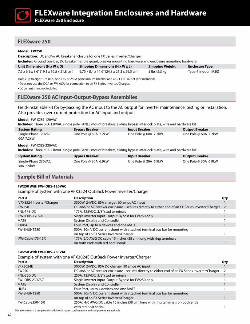
FLEXware 250
Model: FW250 Description: DC and/or AC breaker enclosure for one FX Series Inverter/Charger Includes: Ground bus-bar, DC breaker handle guard, breaker mounting hardware and enclosure mounting hardware Unit Dimensions (H x W x D) Shipping Dimensions (H x W x L) Shipping Weight Enclosure Type 7.5 x 6.5 x 8.6” (19.1 x 16.5 x 21.8 cm) 9.75 x 8.4 x 11.6” (24.8 x 21.3 x 29.5 cm) 5 lbs (2.3 kg) Type-1 indoor (IP30)
Holds up to eight 1 to 80A, one 175 or 250A panel mount breaker and a GFCI AC outlet (not included).
• Does not use the DCA or FW-ACA for connection to an FX Series Inverter/Charger. • DC current shunt not included
FLEXware 250 AC Input-Output-Bypass Assemblies
Field-installable kit for by-passing the AC input to the AC output for inverter maintenance, testing or installation. Also provides over-current protection for AC input and output. Model: FW-IOBS-120VAC Includes: Three 60A 120VAC single pole PANEL mount breakers, sliding bypass interlock plate, wire and hardware kit System Rating Bypass Breaker Input Breaker Output Breaker Single-Phase 120VAC One Pole @ 60A 7.2kW One Pole @ 60A 7.2kW One Pole @ 60A 7.2kW 60A 7.2kW Model: FW-IOBS-230VAC Includes: Three 30A 230VAC single pole PANEL mount breakers, sliding bypass interlock plate, wire and hardware kit
System Rating Bypass Breaker Input Breaker Output Breaker
Single-Phase 230VAC One Pole @ 30A 6.9kW One Pole @ 30A 6.9kW One Pole @ 30A 6.9kW30A 6.9kW
Sample Bill of Materials
FW250 With FW-IOBS-120VAC
Example of system with one VFX3524 OutBack Power Inverter/ChargerPart # Description QtyVFX3524 Inverter/Charger 3500W, 24VDC, 85A charger, 60 amps AC input 1FW250 DC and/or AC breaker enclosure – secures directly to either end of an FX Series Inverter/Charger. 2
PNL-175-DC 175A, 125VDC, 3/8” stud terminals 1FW-IOBS-120VAC Single inverter Input-Output-Bypass for FW250 only 1
MATE System Display and Controller 1HUB4 Four Port, Up to 4 devices and one MATE 1
FW-SHUNT250 500A 50mV DC current shunt with attached terminal bus bar for mounting on top of an FX Series Inverter/Charger 1 FW-Cable175-15R 175A 2/0 AWG DC cable 15 inches (38 cm) long with ring terminals on both ends with red heat shrink 1
FW250 With FW-IOBS-230VAC
Example of system with one VFX3024E OutBack Power Inverter/ChargerPart # Description QtyVFX3024E 3000W, 24VDC, 85A DC charger, 30 amps AC input 1FW250 DC and/or AC breaker enclosure - secures directly to either end of an FX Series Inverter/Charger 2PNL-250-DC 250A, 125VDC, 3/8” stud terminals 1FW-IOBS-230VAC Single inverter Input-Output-Bypass for FW250 only 1MATE System Display and Controller 1HUB4 Four Port, up to 4 devices and one MATE 1FW-SHUNT250 500A 50mV DC current shunt with attached terminal bus bar for mounting on top of an FX Series Inverter/Charger 1FW-Cable250-15R 250A, 4/0 AWG DC cable 15 inches (38 cm) long with ring terminals on both ends with red heat shrink 1 This information is a sample only – additional system configurations and components are available.
FLEXware 250 EnclosureFLEXware Integration Enclosures and Hardware
42
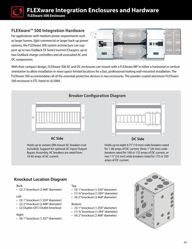
FLEXware™ 500 Integration Hardware For applications with medium power requirements such as larger homes, light commercial or larger back-up power systems, the FLEXware 500 system architecture can sup-port up to two OutBack FX Series Inverter/Chargers, up to two OutBack charge controllers and all associated AC and DC components.
With their compact design, FLEXware 500 AC and DC enclosures can mount with a FLEXware MP in either a horizontal or vertical orientation to allow installation in more space-limited locations for a fast, professional-looking wall-mounted installation. The FLEXware 500 accommodates all of the essential protective devices in two enclosures. The powder-coated aluminum FLEXware 500 enclosure is ETL listed to UL508A.
FLEXware 500 EnclosureFLEXware Integration Enclosures and Hardware
Knockout Location DiagramBack• (2) 2” knockout (2.468” diameter)
Left• (5) 1” knockout (1.359” diameter)• (2) 2” knockout (2.468” diameter)• (2) Duplex GFCI Outlet knockout
Right• (9) 1” knockout (1.357” diameter)
Top• (3) 1” knockout (1.359” diameter)• (1) ¾” knockout (1.093” diameter)• (4) 2” knockout (2.468” diameter)
Bottom• (3) 1” knockout (1.359” diameter)• (1) ¾” knockout (1.093” diameter)• (4) 2” knockout (2.468” diameter)
Breaker Configuration Diagram
Holds up to eight 0.75” (19 mm) wide breakers rated for 1-80 amps of DC current, three 1” (26 mm) wide breakers rated for 100 or 125 amps of DC current, or two 1.5” (32 mm) wide breakers rated for 175 or 250 amps of DC current.
Holds up to sixteen DIN mount AC breakers (not included). Support for optional AC Input-Output-Bypass Assembly. AC breakers are rated from 10-60 amps of AC current.
DC SideAC Side
43
FLEXware 500 Integration Hardware
Model: FW500-DCDescription: DC enclosure which mounts at the DC side of one or two FX Series Inverter/Chargers. Supports up to six terminal bus bars (not including ground bus-bar) and up to three shunt assemblies depending on configuration Includes: Ground bus bar, 500 amp DC shunt assembly, positive bus, breaker mounting hardware, FW-BBUS and enclosure mounting hardware
Unit Dimensions (H x W x D) Shipping Dimensions (H x W x L) Shipping Weight Enclosure Type18.2 x 11.4 x 12.1” (46.2 x 29 x 30.7 cm) 14.5 x 13.4 x 20.3” (36.8 x 34.1 x 51.6 cm) 15 lbs. (6.8 kg) Type-1 indoor (IP30)
Model: FW500-ACDescription: AC enclosure which mounts at the AC side of one or two FX Series Inverter/Chargers. Supports six terminal bus bars and one FW-X240Includes: Ground bus bar, DIN mounting bracket, communication cable conduit and enclosure mounting hardware
Unit Dimensions (H x W x D) Shipping Dimensions (H x W x L) Shipping Weight Enclosure Type18.2 x 11.4 x 12.1” (46.2 x 29 x 30.7 cm) 14.5 x 13.4 x 20.3” (36.8 x 34.1 x 51.6 cm) 15 lbs. (6.8 kg) Type-1 indoor (IP30) • The FW500 system utilizes one FW-MP (mounting plate) and a set of the DCA and FW-ACA conduit adapters for each inverter/charger. • DC and AC breakers, Input-Output-Bypass Assemblies and all other additional components sold separately.
FLEXware 500 AC Input-Output-Bypass Assemblies
Field-installable kit for bypassing the AC input to the AC output for inverter maintenance or installation. Also provides over-current protection.
Model: FW-IOBD-120/240VAC Includes: Six 60A 120VAC single pole DIN mount breakers, sliding bypass interlock plate, wire and hardware kit System Rating Bypass Breaker Input Breaker Output BreakerSplit Phase 120/240VAC Two Poles @ 60A 14.4kW Two Poles @ 60A 14.4kW Two Poles @ 60A 14.4kW60A 14.4kW
Model: FW-IOBD-120VAC Includes: Four 60A 120VAC single pole DIN mount breakers, one 60A 120VAC dual pole DIN mount breaker, sliding bypass interlock plate, wire and hardware kit
System Rating Bypass Breaker Input Breaker Output BreakerSingle-Phase 120VAC Two Poles @ 60A 14.4kW Two Poles @ 60A 14.4kW Two Poles @ 60A 14.4kW120A 14.4kW
Model: FW-IOBD-230VAC Includes: Six 30A 230VAC single pole DIN mount breakers, sliding bypass interlock plate, wire and hardware kit
System Rating Bypass Breaker Input Breaker Output BreakerSingle-Phase 230VAC Two Poles @ 30A 13.8kW Two Poles @ 30A 13.8kW Two Poles @ 30A 13.8kW60A 13.8kW
FLEXware 500 EnclosureFLEXware Integration Enclosures and Hardware
44

FW500 With FW-IOBD-120/240VACExample of system with dual VFX3648 Outback Power Inverter/Chargers in SeriesPart # Description QtyVFX3648 Inverter/Charger 3600W, 48VDC, 45A charger, 60 amps AC input 2FW-ACA AC Conduit Adapter for all FX Series Inverter/Chargers to AC enclosure. 2DCA DC Conduit Adapter for all FX Series Inverter/Chargers to DC enclosure. 2FW500-DC DC breaker enclosure – fits at the DC side of one or two FX Series Inverter/Chargers 1PNL-175-DC 175A, 125VDC breaker with 3/8” stud terminals 2FW500-AC AC breaker enclosure – fits at the AC side of one or two FX Series Inverter/Chargers 1FW-IOBD-120/240VAC Dual inverter Input-Output-Bypass for FW500 1FW-MP Mounting Plate for FW500 or FW1000 system 1MATE System Display and Controller 1HUB4 Four Port, up to 4 devices and one MATE 1FN-DC FLEXnet DC Multi-channel Advanced DC System Monitor 1FW-X240 Auto-transformer 4kVA 120/240VAC 60Hz 1FW-Cable175-36R 175A 2/0 AWG DC cable 36 inches (91.5 cm) long with ring terminals on both 2 ends with red heat shrink FW-Cable175-36W 175A 2/0 AWG DC cable 36 inches (91.5 cm) long with ring terminals on both 2 ends with white heat shrink
FW500 With FW-IOBD-230VAC Example of system with dual VFX3024E OutBack Power Inverter/Charger in ParallelPart# Description QtyVFX3024E 3000W, 24VDC, 85 amps DC charger, 30 amps AC input 2FW-ACA AC Conduit adapter for all FX Series Inverter/Chargers to AC enclosure 2DCA DC Conduit adapter for all FX Series Inverter/Chargers to DC enclosure 2FW500-DC DC breaker enclosure - fits at the DC side of one or two FX Series Inverter/Chargers 1PNL-250-DC 250A, 125VDC, 3/8” stud terminals 2FW500-AC AC breaker enclosure - fits at the AC side of one or two FX Series Inverter/Chargers 1FW-IOBD-230VAC Dual inverter Input-Output-Bypass for FW500 1FW-MP Mounting Plate for FW500 or FW1000 System 1MATE System Display and Controller 1HUB4 Four Port, up to 4 devices and one MATE 1FN-DC FLEXnet DC Multi-channel Advanced DC System Monitor 1FW-Cable250-36R 250A 4/0 AWG DC cable 36 inches (91.5 cm) long with ring terminals on both 2 ends with red heat shrink FW-Cable250-36W 250A 4/0 AWG DC cable 36 inches (91.5 cm) long with ring terminals on both 2 ends with white heat shrink
FW500 With FW-IOBD-120VAC Example of system with one VFX3648 Outback Power Inverter/ChargerPart # Description Qty VFX3648 Inverter/Charger 3600W, 48VDC, 45A charger, 60 amps AC input 1 FW-ACA AC Conduit Adapter for all FX Series Inverter/Chargers to AC enclosure. 1 DCA DC Conduit Adapter for all FX Series Inverter/Chargers to DC enclosure. 1 FW500-DC DC breaker enclosure – fits at the DC side of one or two FX Series Inverter/Chargers 1 PNL-175-DC 175A, 125VDC breaker with 3/8” stud terminals 1 FW500-AC AC breaker enclosure – fits at the AC side of one or two FX Series Inverter/Chargers 1 FW-IOBD-120VAC Dual inverter Input-Output-Bypass for FW500 1 FW-MP Mounting Plate for FW500 or FW1000 system 1 MATE System Display and Controller 1 HUB4 Four Port, up to 4 devices and one MATE 1 FN-DC FLEXnet DC Multi-channel Advanced DC System Monitor 1 FW-Cable175-36R 175A 2/0 AWG DC cable 36 inches (91.5 cm) long with ring terminals on both ends with red heat shrink 1FW-Cable175-36W 175A 2/0 AWG DC cable 36 inches (91.5 cm) long with ring terminals on both ends with white heat shrink 2
FLEXware 500 EnclosureFLEXware Integration Enclosures and Hardware
This information is a sample only – additional system configurations and components are available.
45

Knockout Location Diagram
FLEXware™ 1000 Integration HardwareDesigned for applications with larger power requirements such as large residential, Commercial, or village power systems. The FLEXware 1000 system architecture is capable of supporting up to four OutBack FX Series Inverter/Chargers, four OutBack charge controllers, and all the required AC and DC components and wiring. With their compact design, FLEXware 1000 AC and DC enclosures accommodate all essential protective devices with ample room for additional breakers and large cable connections, and can be mounted either vertically or horizontally. The powder-coated aluminum FLEXware 1000 enclosure is ETL listed to UL508A.
Breaker Configuration Diagram
Holds up to thirty-two DIN mount AC breakers (not included). Support for optional AC Input-Output Bypass Assembly. AC breakers are rated from 10-60 amps AC current.
Holds up to eleven 0.75” (19 mm) wide breakers rated for 1-80 amps of DC current, nine 1” (26 mm) wide breakers rated for 100 or 125 amps of DC current or six 1.5” (32 mm) wide breakers rated for 175 or 250 amps DC current.
Left• (4) 2” knockout (2.468” diameter)• (9) 1” knockout (1.359” diameter)• (2) Duplex GFCI Outlet knockout
Back• (2) 2” knockout (2.468” diameter)• (2) 1” knockout (1.359” diameter)
Right• (17) 1” knockout (1.359” diameter)
Top• (3) 1” knockout (1.359” diameter)• (1) ¾” knockout (1.093” diameter)• (4) 2” knockout (2.468” diameter)
Bottom• (3) 1” knockout (1.359” diameter)• (1) ¾” knockout (1.093” diameter)• (4) 2” knockout (2.468” diameter)
FLEXware 1000 EnclosureFLEXware Integration Enclosures and Hardware
AC Side DC Side
46

FLEXware 1000
Model: FW1000-DC Description: DC enclosure which mounts at the DC side of three or four FX Series Inverter/Chargers. Supports up to eight terminal bus bars (not including GBB) and up to three shunt assemblies depending on configuration Includes: Ground bus bar, 1000 amp DC shunt assembly, positive bus, breaker mounting hardware, enclosure mounting hardware, two FW-SBUS and one FLEXware 1000 breaker bus
Unit Dimensions (H x W x D) Shipping Dimensions (H x W x L) Shipping Weight Enclosure Type38.5 x 11.4 x 12.1” (97.8 x 29.0 x 30.7 cm) 14.5 x 13.6 x 40.6” (36.8 x 34.5 x 103.1 cm) 21 lbs (9.5 kg) Type-1 indoor (IP30)
Model: FW1000-AC Description: AC enclosure which mounts at the AC side of three or four FX Series Inverter/Chargers. Supports eight terminal bus bars and one FW-X240 Includes: Ground bus-bar, two DIN mounting brackets and FLEXware 1000 wiring raceway
Unit Dimensions (H x W x D) Shipping Dimensions (H x W x L) Shipping Weight Enclosure Type38.5 x 11.4 x 12.1” (97.8 x 29.0 x 30.7 cm) 14.5 x 13.6 x 40.6” (36.8 x 34.5 x 103.1 cm) 21 lbs (9.5 kg) Type-1 indoor (IP30)
• The FW1000 system utilizes two FW-MPs (mounting plates) and a set of the DCA and FW-ACA conduit adapters for each inverter/charger. • DC and AC breakers, Input-Output-Bypass Assemblies and all other additional components sold separately.
FLEXware 1000 AC Input-Output-Bypass Assemblies
Field installable kit for bypassing the AC input to the AC output for inverter maintenance or installation. Also provides over-current protection.
Model: FW-IOBT-120/208VACIncludes: Nine 60A 120VAC single pole DIN mount breakers, sliding bypass interlock plate, wire and hardware kit
System Rating Bypass Breaker Input Breaker Output BreakerThree-Phase 120/208VAC Three Poles @ 60A 21.6kW Three Poles @ 60A 21.6kW Three Poles @ 60A 21.6kW60A 21.6kW
Model: FW-IOBT-230/400VAC Includes: Nine 30A 230VAC single pole DIN mount breakers, sliding bypass interlock plate, wire and hardware kit
System Rating Bypass Breaker Input Breaker Output BreakerThree-Phase 230/400VAC Three Poles @ 30A 20.7kW Three Poles @ 30A 20.7kW Three Poles @ 30A 20.7kW30A 20.7kW
Model: FW-IOBQ-120/240VAC Includes: Eight 60A 120VAC single pole DIN mount breakers, two 60A 120VAC dual pole DIN mount breakers, sliding bypass interlock plate, wire and hardware kit
System Rating Bypass Breaker Input Breaker Output BreakerSplit Phase 120/240VAC Four Poles @ 60A 28.8kW Four Poles @ 60A 28.8kW Four Poles @ 60A 28.8kW120A 28.8kW
Model: FW-IOBQ-230VAC Includes: Twelve 30A 230VAC single pole DIN mount breakers, sliding bypass interlock plate, wire and hardware kit
System Rating Bypass Breaker Input Breaker Output BreakerSingle-Phase 230VAC Four Poles @ 30A 27.6kW Four Poles @ 30A 27.6kW Four Poles @ 30A 27.6kW120A 27.6kW
FLEXware 1000 EnclosureFLEXware Integration Enclosures and Hardware
47
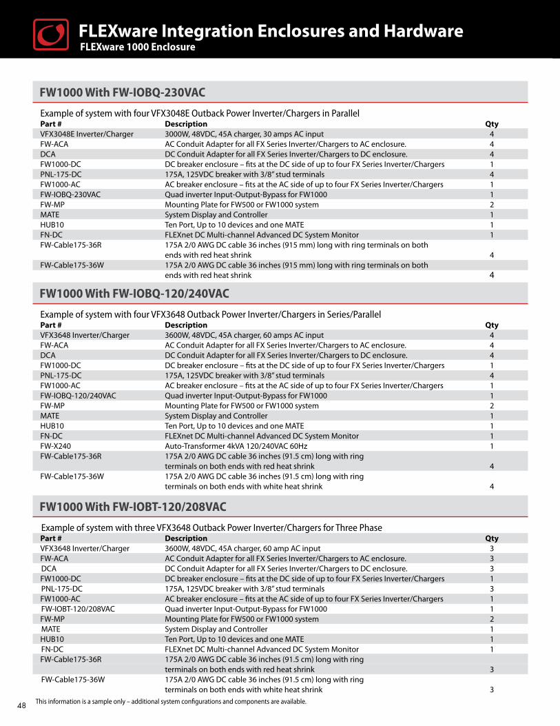
FW1000 With FW-IOBQ-230VAC
Example of system with four VFX3048E Outback Power Inverter/Chargers in Parallel Part # Description QtyVFX3048E Inverter/Charger 3000W, 48VDC, 45A charger, 30 amps AC input 4FW-ACA AC Conduit Adapter for all FX Series Inverter/Chargers to AC enclosure. 4DCA DC Conduit Adapter for all FX Series Inverter/Chargers to DC enclosure. 4FW1000-DC DC breaker enclosure – fits at the DC side of up to four FX Series Inverter/Chargers 1PNL-175-DC 175A, 125VDC breaker with 3/8” stud terminals 4FW1000-AC AC breaker enclosure – fits at the AC side of up to four FX Series Inverter/Chargers 1FW-IOBQ-230VAC Quad inverter Input-Output-Bypass for FW1000 1FW-MP Mounting Plate for FW500 or FW1000 system 2MATE System Display and Controller 1HUB10 Ten Port, Up to 10 devices and one MATE 1FN-DC FLEXnet DC Multi-channel Advanced DC System Monitor 1FW-Cable175-36R 175A 2/0 AWG DC cable 36 inches (915 mm) long with ring terminals on both ends with red heat shrink 4FW-Cable175-36W 175A 2/0 AWG DC cable 36 inches (915 mm) long with ring terminals on both ends with red heat shrink 4
FW1000 With FW-IOBQ-120/240VAC
Example of system with four VFX3648 Outback Power Inverter/Chargers in Series/ParallelPart # Description QtyVFX3648 Inverter/Charger 3600W, 48VDC, 45A charger, 60 amps AC input 4FW-ACA AC Conduit Adapter for all FX Series Inverter/Chargers to AC enclosure. 4DCA DC Conduit Adapter for all FX Series Inverter/Chargers to DC enclosure. 4FW1000-DC DC breaker enclosure – fits at the DC side of up to four FX Series Inverter/Chargers 1PNL-175-DC 175A, 125VDC breaker with 3/8” stud terminals 4FW1000-AC AC breaker enclosure – fits at the AC side of up to four FX Series Inverter/Chargers 1FW-IOBQ-120/240VAC Quad inverter Input-Output-Bypass for FW1000 1FW-MP Mounting Plate for FW500 or FW1000 system 2MATE System Display and Controller 1HUB10 Ten Port, Up to 10 devices and one MATE 1FN-DC FLEXnet DC Multi-channel Advanced DC System Monitor 1FW-X240 Auto-Transformer 4kVA 120/240VAC 60Hz 1FW-Cable175-36R 175A 2/0 AWG DC cable 36 inches (91.5 cm) long with ring terminals on both ends with red heat shrink 4FW-Cable175-36W 175A 2/0 AWG DC cable 36 inches (91.5 cm) long with ring terminals on both ends with white heat shrink 4
FW1000 With FW-IOBT-120/208VAC
Example of system with three VFX3648 Outback Power Inverter/Chargers for Three Phase Part # Description Qty VFX3648 Inverter/Charger 3600W, 48VDC, 45A charger, 60 amp AC input 3FW-ACA AC Conduit Adapter for all FX Series Inverter/Chargers to AC enclosure. 3DCA DC Conduit Adapter for all FX Series Inverter/Chargers to DC enclosure. 3FW1000-DC DC breaker enclosure – fits at the DC side of up to four FX Series Inverter/Chargers 1PNL-175-DC 175A, 125VDC breaker with 3/8” stud terminals 3FW1000-AC AC breaker enclosure – fits at the AC side of up to four FX Series Inverter/Chargers 1FW-IOBT-120/208VAC Quad inverter Input-Output-Bypass for FW1000 1FW-MP Mounting Plate for FW500 or FW1000 system 2MATE System Display and Controller 1HUB10 Ten Port, Up to 10 devices and one MATE 1FN-DC FLEXnet DC Multi-channel Advanced DC System Monitor 1FW-Cable175-36R 175A 2/0 AWG DC cable 36 inches (91.5 cm) long with ring terminals on both ends with red heat shrink 3FW-Cable175-36W 175A 2/0 AWG DC cable 36 inches (91.5 cm) long with ring terminals on both ends with white heat shrink 3
FLEXware 1000 EnclosureFLEXware Integration Enclosures and Hardware
This information is a sample only – additional system configurations and components are available.48

FLEXware™ MP Mounting Plate
The FLEXware MP is a one-piece, powder-coated aluminum mounting plate for FLEXware 500 and FLEXware 1000 enclosures. Using stainless steel mounting hardware, the integrated locating bolts make installation quick and easy by providing guides to line up enclosures and inverter/chargers. A single FLEXware MP is designed to accommodate a FLEXware 500 while two FLEXware MPs are utilized in a FLEXware 1000 configuration.
FLEXware Mounting Plate
Model: FW-MP Description: FLEXware system mounting plate
Unit Dimensions (H x W x D) Shipping Dimensions (H x W x L) Shipping Weight20.3 x 46.3 x .8” (51.6 x 117.6 x 2.1 cm) 1.15 x 22.9 x 48.4” (2.9 x 58.2 x 123 cm) 14 lbs (6.4 kg)
Single MP Configuration for FLEXware 500
Side View of Integrated Locating Bolts
Angled View of Integrated Locating Bolts
FLEXware™ Mounting Plate FLEXware Integration Enclosures and Hardware
49

FLEXware PV Combiner Box Specifications
FWPV-8 FWPV-12Enclosure Material Powder coated aluminum with stainless steel hardware
Mounting Options Vertical wall mount, pole mount or sloped roof mount to 14 degrees incline (3 in 12 roof pitch)
Enclosure Rating Outdoor Rainproof, NEMA 3R
Enclosure Security Padlock hole in chassis and cover for up to 3/8 inch padlock
Output Terminals #14 to 2/0 AWG (2.08 to 67.4 mm²) #14 - 2/0 AWG (2.08 to 67.4 mm²)
Two box lug terminals included Two box lug terminals included
Number of Separate Circuits One Circuit One or Two Circuits
Total Maximum Current 120A 180A
Number of 150VDC Breakers Up to 8 Up to 12 (two groups of six)
Number of Fuse Holders Up to 6 Up to 8 (two groups of four)
Input Terminal 150VDC Breakers / #14 to 6 AWG (2.08 to 13.3 mm²) 150VDC Breakers / #14 to 16 AWG (2.08 to 3.3 mm²)
600VDC Fuse / #14 to 10 AWG (2.08 to 5.26 mm²) 600VDC Fuse / #14 to 10 AWG (2.08 to 5.26 mm²)
Certifications ETL Listed to UL1741, UL67, CSA22.2 #29 ETL Listed to UL1741, UL67, CSA22.2 #29
Weight Unit 4.4 lbs (2.0 kg) 5.9 lbs (2.7 kg)
Shipping 5.5 lbs (2.5 kg) 7.4 lbs (3.3 kg)
Dimensions H x W x L Unit 15.2 x 9.2 x 3.9” (38.7 x 23.3 x 9.9 cm) 15.2 x 12.7 x 3.9” (38.7 x 32.2 x 9.9 cm)
Shipping 19 x 9.5 x 4.3” (48.3 x 24.1 x 10.9 cm) 19 x 13 x 4.3” (48.3 x 33 x 10.9 cm)
FLEXware™ PV Combiner BoxesThe FLEXware PV Combiner Box Series takes installations to the next level and sets a new standard for PV balance-of-system hardware. Ideal for both small and large systems, the FLEXware PV8 and FLEXware PV12 accommodates an application’s overcurrent protection requirements. From 150VDC breakers for low voltage V systems, to 600VDC fuse holders for high voltage PV systems, the FLEXware PV Combiner series handles it all.
Designed to survive in outdoor environments, the rainproof, UL-type 3R powder coated aluminum chassis can be mounted on a wall, sloped roof or pole. The unique angled negative terminal bus bar design make wiring fast and easy without the common problem of larger output conductors blocking access to the smaller input terminals. Dual output lug terminals are included for up to 2/0 AWG conductors. The tinted flame-retardant polycarbonate “dead” front panel creates a clean appearance while preventing accidental contact with the live terminals and is easily removable during installation.
Use appropriate wire size in accordance with NEC.
FLEXware™ PV Combiner Boxes FLEXware Integration Enclosures and Hardware
50
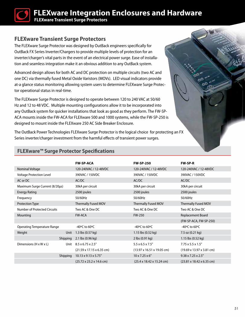
FLEXware™ Surge Protector Specifications
FW-SP-ACA FW-SP-250 FW-SP-R
Nominal Voltage 120-240VAC / 12-48VDC 120-240VAC / 12-48VDC 120-240VAC / 12-48VDC
Voltage Protection Level 390VAC / 150VDC 390VAC / 150VDC 390VAC / 150VDC
AC or DC AC/DC AC/DC AC/DC
Maximum Surge Current (8/20μs) 30kA per circuit 30kA per circuit 30kA per circuit
Energy Rating 2500 joules 2500 joules 2500 joules
Frequency 50/60Hz 50/60Hz 50/60Hz
Protection Type Thermally Fused MOV Thermally Fused MOV Thermally Fused MOV
Number of Protected Circuits Two AC & One DC Two AC & One DC Two AC & One DC
Mounting FW-ACA FW-250 Replacement Board
(FW-SP-ACA, FW-SP-250)
Operating Temperature Range -40ºC to 60ºC -40ºC to 60ºC -40ºC to 60ºC
Weight Unit 1.3 lbs (0.57 kg) 1.15 lbs (0.52 kg) 7.5 oz (0.21 kg)
Shipping 2.1 lbs (0.96 kg) 2 lbs (0.91 kg) 1.15 lbs (0.52 kg)
Dimensions (H x W x L) Unit 8.5 x 6.75 x 2.5” 5.5 x 6.5 x 7.5” 7.75 x 5.5 x 1.5”
(21.59 x 17.15 x 6.35 cm) (13.97 x 16.51 x 19.05 cm) (19.69 x 13.97 x 3.81 cm)
Shipping 10.13 x 9.13 x 5.75” 10 x 7.25 x 6” 9.38 x 7.25 x 2.5”
(25.72 x 23.2 x 14.6 cm) (25.4 x 18.42 x 15.24 cm) (23.81 x 18.42 x 6.35 cm)
FLEXware Transient Surge Protectors The FLEXware Surge Protector was designed by OutBack engineers specifically for OutBack FX Series Inverter/Chargers to provide multiple levels of protection for an inverter/charger’s vital parts in the event of an electrical power surge. Ease of installa-tion and seamless integration make it an obvious addition to any OutBack system.
Advanced design allows for both AC and DC protection on multiple circuits (two AC and one DC) via thermally fused Metal Oxide Varistors (MOVs). LED visual indicators provide at-a glance status monitoring allowing system users to determine FLEXware Surge Protec-tor operational status in real-time.
The FLEXware Surge Protector is designed to operate between 120 to 240 VAC at 50/60 Hz and 12 to 48 VDC. Multiple mounting configurations allow it to be incorporated into any OutBack system for quicker installations that look as good as they perform. The FW-SP-ACA mounts inside the FW-ACA for FLEXware 500 and 1000 systems, while the FW-SP-250 is designed to mount inside the FLEXware 250 AC Side Breaker Enclosure.
The OutBack Power Technologies FLEXware Surge Protector is the logical choice for protecting an FX Series inverter/charger investment from the harmful effects of transient power surges.
FLEXware Transient Surge Protectors FLEXware Integration Enclosures and Hardware
51

Auto Transformer
Step-Up
Step-Down
Generator Balancing
OutBack Balancing
240 VACLoads
120 VACLoads
120/240 VACLoads
120/240 VACLoads
Inverter/Charger PSX-240
PSX-240 Inverter/Charger120/240 VAC Generator
PSX-240 Inverter/Charger
Inverter/Charger PSX-240
120/240 VAC Generator
120/240 VAC Generator
PSX-240 Auto-Transformer
The OutBack PSX-240 (6kVA) auto-transformer can be used for step-up, step-down, generator and split-phase output balancing or as a series stacked inverter to load balancing autoformer. Incorporating a transformer with 120V / 30A primary and secondary side, a temperature activated cooling fan and a 25 amp dual pole breaker in a steel enclosure, the PSX-240 is ready to install in your custom application. Use for 120 or 240 VAC 60 Hz systems only.
Weight Unit 37.7 lbs (17.1 kg) Shipping 39.5 lbs (17.9 kg) Dimensions (H x W x L) Unit 6.25 x 8 x 12.5” (15.9 x 20.3 x 31.75 cm) Shipping 10.25 x 12.25 x 16.25” (26 x 31.1 x 33 cm)
FW-X240 Auto-Transformer
Designed to be housed within the FLEXware 500 or FLEXware 1000 AC enclosures, the FW-X240 (4 kVA) auto-transformer can be used for step- up, step-down, generator and split-phase output balancing or as a series stacked inverter to load balancing autoformer. Includes transformer, 25 amp dual pole breaker and mounting hardware. Use for 120 or 240 VAC 60 Hz systems only.
Weight Unit 28.4 lbs (12.9 kg) Shipping 32.5 lbs (14.7 kg) Dimensions (H x W x L) Unit 5.25 x 6 x 6.5” (27 x 16 x 3 cm) Shipping 10.75 x 10.75 x 10.75” (27 x 27 x 27 cm)
52
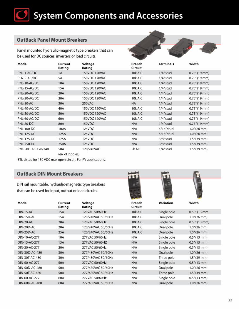
System Components and Accessories
OutBack Panel Mount Breakers
Panel mounted hydraulic-magnetic type breakers that can be used for DC sources, inverters or load circuits.
Model Current Voltage Branch Terminals Width Rating Rating Circuit
PNL-1-AC/DC 1A 150VDC 120VAC 10k AIC 1/4” stud 0.75” (19 mm)
PLN-5-AC/DC 5A 150VDC 120VAC 10k AIC 1/4” stud 0.75” (19 mm)
PNL-10-AC/DC 10A 150VDC 120VAC 10k AIC 1/4” stud 0.75” (19 mm)
PNL-15-AC/DC 15A 150VDC 120VAC 10k AIC 1/4” stud 0.75” (19 mm)
PNL-20-AC/DC 20A 150VDC 120VAC 10k AIC 1/4” stud 0.75” (19 mm)
PNL-30-AC/DC 30A 150VDC 120VAC 10k AIC 1/4” stud 0.75” (19 mm)
PNL-30-AC 30A 250VAC NA 1/4” stud 0.75” (19 mm)
PNL-40-AC/DC 40A 150VDC 120VAC 10k AIC 1/4” stud 0.75” (19 mm)
PNL-50-AC/DC 50A 150VDC 120VAC 10k AIC 1/4” stud 0.75” (19 mm)
PNL-60-AC/DC 60A 150VDC 120VAC 10k AIC 1/4” stud 0.75” (19 mm)
PNL-80-DC 80A 150VDC N/A 1/4” stud 0.75” (19 mm)
PNL-100-DC 100A 125VDC N/A 5/16” stud 1.0” (26 mm)
PNL-125-DC 125A 125VDC N/A 5/16” stud 1.0” (26 mm)
PNL-175-DC 175A 125VDC N/A 3/8” stud 1.5” (39 mm)
PNL-250-DC 250A 125VDC N/A 3/8” stud 1.5” (39 mm)
PNL-50D-AC-120/240 50A 120/240VAC 5k AIC 1/4” stud 1.5” (39 mm)
(ea. of 2 poles)
ETL Listed for 150 VDC max open circuit. For PV applications.
OutBack DIN Mount Breakers
DIN rail mountable, hydraulic-magnetic type breakers
that can be used for input, output or load circuits.
Model Current Voltage Branch Variation Width Rating Rating Circuit
DIN-15-AC 15A 120VAC 50/60Hz 10k AIC Single pole 0.50” (13 mm
DIN-15D-AC 15A 120/240VAC 50/60Hz 10k AIC Dual pole 1.0” (26 mm)
DIN-20-AC 20A 120VAC 50/60Hz 10k AIC Single pole 0.50” (13 mm)
DIN-20D-AC 20A 120/240VAC 50/60Hz 10k AIC Dual pole 1.0” (26 mm)
DIN-25D-AC 25A 120/240VAC 50/60Hz 10k AIC Dual pole 1.0” (26 mm)
DIN-10-AC-277 10A 277VAC 50/60Hz N/A Single pole 0.5” (13 mm)
DIN-15-AC-277 15A 277VAC 50/60HZ N/A Single pole 0.5” (13 mm)
DIN-30-AC-277 30A 277VAC 50/60Hz N/A Single pole 0.5” (13 mm)
DIN-30D-AC-480 30A 277/480VAC 50/60Hz N/A Dual pole 1.0” (26 mm)
DIN-30T-AC-480 30A 277/480VAC 50/60Hz N/A Three pole 1.5” (39 mm)
DIN-50-AC-277 50A 277VAC 50/60Hz N/A Single pole 0.5” (13 mm)
DIN-50D-AC-480 50A 277/480VAC 50/60Hz N/A Dual pole 1.0” (26 mm)
DIN-50T-AC-480 50A 277/480VAC 50/60Hz N/A Three pole 1.5” (39 mm)
DIN-60-AC-277 60A 277VAC 50/60Hz N/A Single pole 0.5” (13 mm)
DIN-60D-AC-480 60A 277/480VAC 50/60Hz N/A Dual pole 1.0” (26 mm)
53

System Components and Accessories
OutBack PV Ground-Fault Detection and Interruption System
Ground fault detection and interruption is required by NEC for PV arrays mounted on or within a specified vicinity of residential dwelling roofs as a safety precaution. The OutBack PV Ground-Fault Detection and Interruption System protects wiring and system components for one, two or four PV arrays when used in a GSLC, FLEXware 250, FLEXware 500 or FLEXware 1000.
Model Description Terminals Width
PNL-GFDI-80 PV Ground-Fault Detector Interrupter
80A 150VDC single pole panel mount 1/4” stud 1.15” (3.85cm)
PNL-GFDI-80D PV Ground-Fault Detector Interrupter
80A 150VDC two pole panel mount 1/4” stud 2.65” (5.73cm)
PNL-GFDI-80Q PV Ground-Fault Detector Interrupter
80A 150VDC four pole panel mount 1/4” stud 2.775” (9.59cm)
Uses two, three or five 3/4” wide panel mount breaker spaces
DC Bus Bars
OutBack DC bus bars are designed to enable the most complex of code compliant DC cable connections.
Model Description Includes
FW-BBUS Breaker Bus allows connection of two 175-250A, three 100-125A Plated copper plate rated
four 1-80 amps DC breakers or three 500 amps DC current shunts for 500A and two 5/16 inch bolts for mounting
FW-SBUS Shunt Bus allows up to four high current cable connections on Two 3/8 inch bolts solid
same side of DC shunt brass rated for 1000A
FW-CBUS-8 Combiner Bus connects up to eight DIN mounted breakers or six Two 2/0 AWG box lug
DIN mounted fuse holders terminals - plated copper
FW-CBUS-12 Combiner Bus connects up to twelve DIN mounted breakers or eight Two 2/0 AWG box lug
DIN mounted fuse holders terminals - plated copper
When used with an amp hour meter, OutBack Power Technologies DC current shunt kits can provide valuable insight into the status of batteries or DC power source. One shunt kit is included standard on FLEXware 500 and FLEXware 1000 DC enclosures.
Model Description Includes
FW-SHUNT250 500 amps DC current shunt with terminal bus bar Shunt, mounting hardware and terminal bus bar
for mounting on top of the FX Series Inverter/Charger for connection to FX Inverter’s DC negative terminal
FW-SHUNT500 500 amps DC current shunt with Shunt, terminal bus bar and one white
terminal bus bar insulator and mounting screws
FW-BBUS FW-SBUS FW-CBUS-12
FW-CBUS-8
FW-SHUNT500
DC Current Shunts
54

FW-SHUNT500
Conduit Adapters
Allows connection of the FX and VFX Series Inverter/Chargers to FLEXware 500 and FLEXware 1000 enclosures, one FW-ACA and DCA required per FX Series Inverter/Charger.
Model Description Includes
FW-ACA Adapter for AC end of FX Series Inverter/Charger FW-ACA and mounting hardware
DCA Adapter for DC end of FX Series Inverter/Charger DCA, bushing and mounting hardware
Mounting Brackets
FW-CCB and FW-CCB2 mounting brackets allow OutBack Power Technologies
charge controllers to be mounted on the side of FW500-DC or FW1000-DC
enclosures. FW-CCB2-T mounting bracket allows OutBack Power Technologies
charge controllers to be mounted on the top of FW500-DC or FW1000-DC
enclosures. FW-MB1 mounting bracket allows mounting OutBack Power
charge controllers and MATE system displays to FLEXware 500,
FLEXware 1000 and Radian enclosures.
Model Description
FW-CCB Bracket for mounting a single FLEXmax Series Charge Controller on the side of FW500 and FW1000 enclosures
FW-CCB2 Bracket for mounting two FLEXmax Series Charge Controllers on the side of FW500 and FW1000 enclosures
FW-CCB2-T Bracket for top mounting two FLEXmax Series Charge Controllers on the top of FW500 and FW1000 enclosures
FW-MB1 Bracket for mounting a MATE System Display on the side of FW500 and FW1000 enclosures
FW-MB2 Bracket for mounting a MATE2 System Display on the side of FW500 and FW1000 enclosures
FW-MB3 Bracket for mounting a MATE3 System Display on the side of Radian, GSLC, FW500 and FW1000 DC enclosures
FW-MB3-F Flat-mount MATE3 Mounting Plate for installation over standard electrical boxes
FW-MB3-S Surface-mount MATE3 Mounting Bracket
DIN Rail End Clamp
Model Description Width
FW-EC-DIN DIN rail mountable securing device for DIN rail mountable fuses or breakers. .4” (10 mm)
FW-CCB2FW-CCB2-T
FW-MB1
FW-MB3 FW-MB3-F FW-MB3-S
System Components and Accessories
55

DC Cable Assemblies
DC interconnect cable assemblies for wiring between inverter/chargers and breakers or DC shunts. Can also be used as battery interconnects. The THW type cable assemblies are UL listed and NEC compliant with a maximum voltage rating of 1000VDC and a temperature rating of 105°C.
Model Description Hole to hole length
FW-CABLE250-15R 250A 4/0 AWG (11.7 mm) DC cable 15 inches (38 cm) long with ring terminals 19” (48.3 cm)
on both ends and red heat shrink. For connection from 250 amp
DC breaker to inverter positive terminal. .
FW-CABLE175-15R 175A 2/0 AWG (9.26 mm) DC cable 15 inches (38 cm) long with ring terminals 19” (48.3 cm)
on both ends and red heat shrink. For connection from 175 amp
DC breaker to inverter positive terminal.
FW-CABLE250-36R 250A 4/0 AWG (11.7 mm) DC cable 36 inches (91.5 cm) long with ring terminals 40” (101.6 cm)
on both ends and red heat shrink. For connection from 250 amp
DC breaker to inverter positive terminal.
FW-CABLE175-36R 175A 2/0 AWG (9.26 mm) DC cable 36 inches (91.5 cm) long with ring terminals 40” (101.6 cm)
on both ends and red heat shrink. For connection from 175 amp
DC breaker to inverter positive terminal.
FW-CABLE250-36W 250A 4/0 AWG (11.7 mm) DC cable 36 inches (91.5 cm) long with ring terminals 40” (101.6 cm)
on both ends and white heat shrink. For connection from DC current
shunt to inverter negative terminal.
FW-CABLE175-36W 175A 2/0 AWG (9.26 mm) DC cable 36 inches (91.5 cm) long with ring terminals 40” (101.6 cm)
on both ends and white heat shrink. For connection from DC current
shunt to inverter negative terminal.
• All ring lugs have 3/8” (9.53 mm) diameter hole.
System Components and Accessories
OutBack DC DIN Mount Breakers
DIN rail mount breakers are hydraulic-magnetic type and are not affected by high ambient temperatures.
Model Current Rating Voltage Rating* Terminals Width
DIN-1-DC 1A 125VDC #14 to 2 AWG clamp terminals 0.5” (13 mm)
DIN-2-DC 2A 150VDC #14 to 2 AWG clamp terminals 0.5” (13 mm)
DIN-3-DC 3A 150VDC #14 to 2 AWG clamp terminals 0.5” (13 mm)
DIN-4-DC 4A 150VDC #14 to 2 AWG clamp terminals 0.5” (13 mm)
DIN-5-DC 5A 150VDC #14 to 2 AWG clamp terminals 0.5” (13 mm)
DIN-6-DC 6A 150VDC #14 to 2 AWG clamp terminals 0.5” (13 mm)
DIN-8-DC 8A 150VDC #14 to 2 AWG clamp terminals 0.5” (13 mm)
DIN-9-DC 9A 150VDC #14 to 2 AWG clamp terminals 0.5” (13 mm)
DIN-10-DC 10A 150VDC #14 to 2 AWG clamp terminals 0.5” (13 mm)
DIN-15-DC 15A 150VDC #14 to 2 AWG clamp terminals 0.5” (13 mm)
DIN-20-DC 20A 125VDC #14 to 2 AWG clamp terminals 0.5” (13 mm)
DIN-30-DC 30A 125VDC #14 to 2 AWG clamp terminals 0.5” (13 mm)
DIN-50-DC 50A 125VDC #14 to 2 AWG clamp terminals 0.5” (13 mm)
DIN-60-DC 60A 125VDC #14 to 2 AWG clamp terminals 0.5” (13 mm)
* Approved for maximum VOC of 15O VDC by ETL for PV array applications only.
56
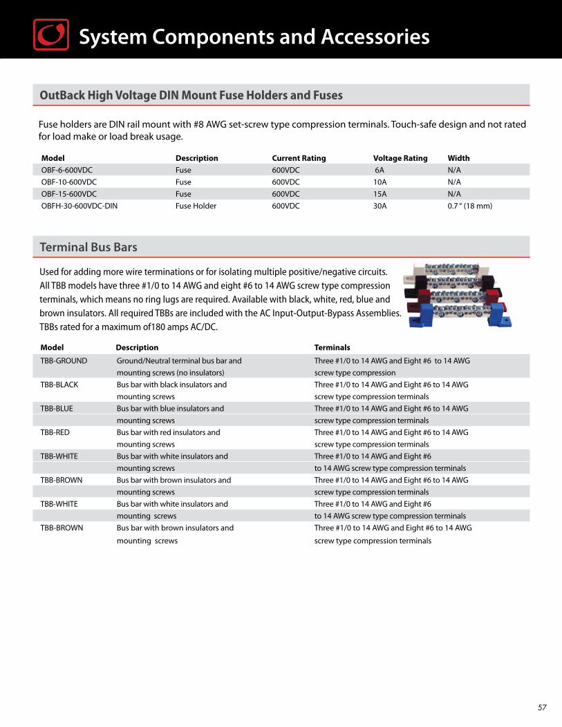
System Components and Accessories
OutBack High Voltage DIN Mount Fuse Holders and Fuses
Fuse holders are DIN rail mount with #8 AWG set-screw type compression terminals. Touch-safe design and not rated for load make or load break usage.
Model Description Current Rating Voltage Rating Width
OBF-6-600VDC Fuse 600VDC 6A N/A
OBF-10-600VDC Fuse 600VDC 10A N/A
OBF-15-600VDC Fuse 600VDC 15A N/A
OBFH-30-600VDC-DIN Fuse Holder 600VDC 30A 0.7 “ (18 mm)
Terminal Bus Bars
Used for adding more wire terminations or for isolating multiple positive/negative circuits. All TBB models have three #1/0 to 14 AWG and eight #6 to 14 AWG screw type compression terminals, which means no ring lugs are required. Available with black, white, red, blue and brown insulators. All required TBBs are included with the AC Input-Output-Bypass Assemblies. TBBs rated for a maximum of180 amps AC/DC.
Model Description Terminals
TBB-GROUND Ground/Neutral terminal bus bar and Three #1/0 to 14 AWG and Eight #6 to 14 AWG
mounting screws (no insulators) screw type compression
TBB-BLACK Bus bar with black insulators and Three #1/0 to 14 AWG and Eight #6 to 14 AWG
mounting screws screw type compression terminals
TBB-BLUE Bus bar with blue insulators and Three #1/0 to 14 AWG and Eight #6 to 14 AWG
mounting screws screw type compression terminals
TBB-RED Bus bar with red insulators and Three #1/0 to 14 AWG and Eight #6 to 14 AWG
mounting screws screw type compression terminals
TBB-WHITE Bus bar with white insulators and Three #1/0 to 14 AWG and Eight #6
mounting screws to 14 AWG screw type compression terminals
TBB-BROWN Bus bar with brown insulators and Three #1/0 to 14 AWG and Eight #6 to 14 AWG
mounting screws screw type compression terminals
TBB-WHITE Bus bar with white insulators and Three #1/0 to 14 AWG and Eight #6
mounting screws to 14 AWG screw type compression terminals
TBB-BROWN Bus bar with brown insulators and Three #1/0 to 14 AWG and Eight #6 to 14 AWG
mounting screws screw type compression terminals
57
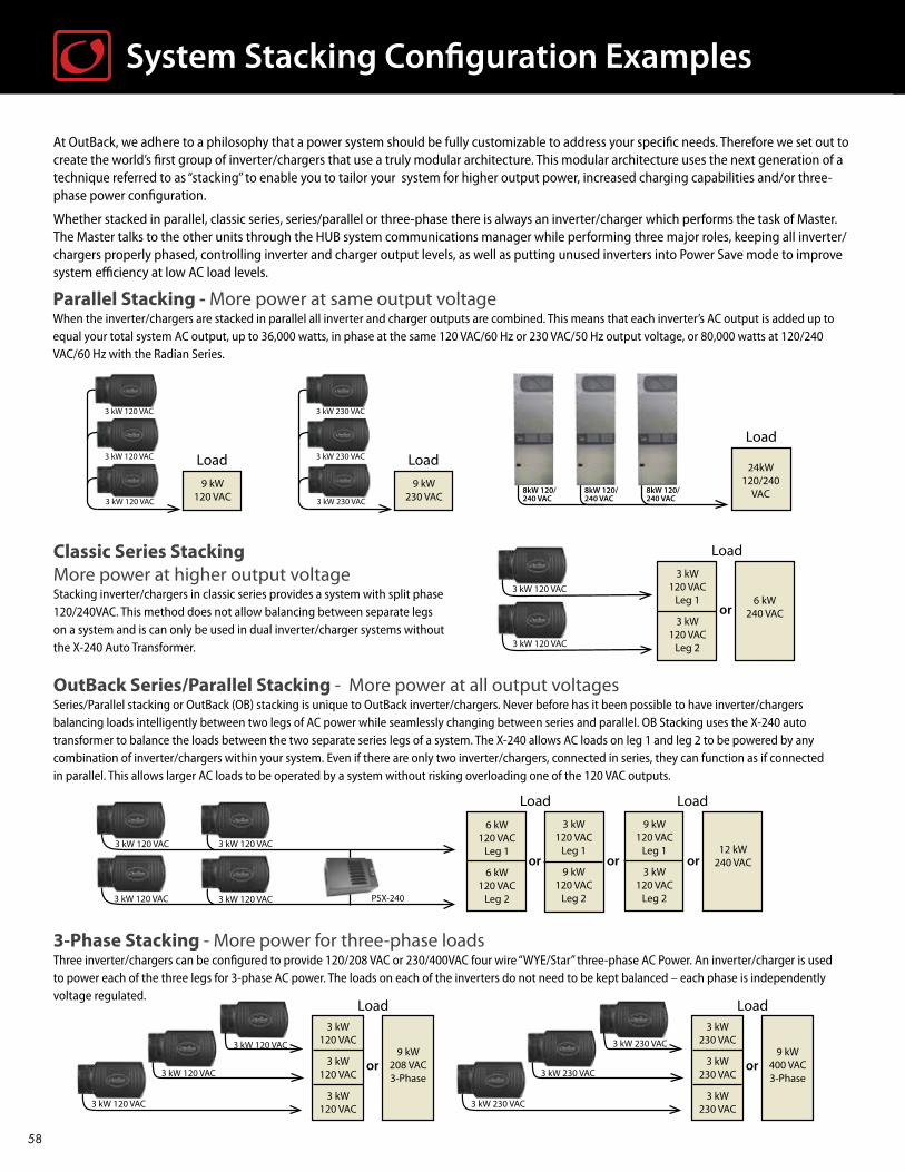
System Stacking Configuration Examples
At OutBack, we adhere to a philosophy that a power system should be fully customizable to address your specific needs. Therefore we set out to create the world’s first group of inverter/chargers that use a truly modular architecture. This modular architecture uses the next generation of a technique referred to as “stacking” to enable you to tailor your system for higher output power, increased charging capabilities and/or three-phase power configuration.
Whether stacked in parallel, classic series, series/parallel or three-phase there is always an inverter/charger which performs the task of Master. The Master talks to the other units through the HUB system communications manager while performing three major roles, keeping all inverter/chargers properly phased, controlling inverter and charger output levels, as well as putting unused inverters into Power Save mode to improve system efficiency at low AC load levels.
Parallel Stacking - More power at same output voltage When the inverter/chargers are stacked in parallel all inverter and charger outputs are combined. This means that each inverter’s AC output is added up to equal your total system AC output, up to 36,000 watts, in phase at the same 120 VAC/60 Hz or 230 VAC/50 Hz output voltage, or 80,000 watts at 120/240 VAC/60 Hz with the Radian Series.
3 kW120 VAC
Leg 1
3 kW120 VAC
Leg 2
6 kW240 VACor
or
Load
Load
3-Phase Stacking - More power for three-phase loadsThree inverter/chargers can be configured to provide 120/208 VAC or 230/400VAC four wire “WYE/Star” three-phase AC Power. An inverter/charger is used to power each of the three legs for 3-phase AC power. The loads on each of the inverters do not need to be kept balanced – each phase is independently voltage regulated.
OutBack Series/Parallel Stacking - More power at all output voltagesSeries/Parallel stacking or OutBack (OB) stacking is unique to OutBack inverter/chargers. Never before has it been possible to have inverter/chargers balancing loads intelligently between two legs of AC power while seamlessly changing between series and parallel. OB Stacking uses the X-240 auto transformer to balance the loads between the two separate series legs of a system. The X-240 allows AC loads on leg 1 and leg 2 to be powered by any combination of inverter/chargers within your system. Even if there are only two inverter/chargers, connected in series, they can function as if connected in parallel. This allows larger AC loads to be operated by a system without risking overloading one of the 120 VAC outputs.
Classic Series Stacking More power at higher output voltage Stacking inverter/chargers in classic series provides a system with split phase 120/240VAC. This method does not allow balancing between separate legs on a system and is can only be used in dual inverter/charger systems without the X-240 Auto Transformer.
3 kW 120 VAC
3 kW 120 VAC
3 kW 120 VAC 3 kW 120 VAC
3 kW 120 VAC 3 kW 120 VAC PSX-240
or
Load
3 kW 120 VAC
3 kW 120 VAC
3 kW 120 VAC
3 kW120 VAC
3 kW120 VAC
3 kW120 VAC
9 kW208 VAC3-Phase
or
Load
3 kW 230 VAC
3 kW 230 VAC
3 kW 230 VAC
3 kW230 VAC
3 kW230 VAC
3 kW230 VAC
9 kW400 VAC3-Phase
9 kW120 VAC
Leg 1
3 kW120 VAC
Leg 2
12 kW240 VACor
Load
6 kW120 VAC
Leg 1
6 kW120 VAC
Leg 2
or
3 kW120 VAC
Leg 1
9 kW120 VAC
Leg 2
3 kW 120 VAC
9 kW120 VAC
Load3 kW 120 VAC
3 kW 120 VAC
3 kW 230 VAC
9 kW230 VAC
Load3 kW 230 VAC
3 kW 230 VAC8kW 120/240 VAC
8kW 120/240 VAC
8kW 120/240 VAC
24kW 120/240
VAC
Load
58


Corporate Headquarters
5917 195th St NE
Arlington, WA 98223 USA
Phone: 360.435.6030
Fax: 360.435.6019
European Office
Hansastrasse 8
D-91126
Schwabach, Germany
Phone: +49.9122.79889.0
Fax: +49.9122.79889.21
Asia Office
Suite 1903, 19/F., Tower 1
33 Canton Road, Tsim Sha Tsui
China Hong Kong City, Kowloon
Hong Kong
Phone: +852.2736.8663
Fax: +852.2199.7988
Latin American Office
15105 Cedar Bluff Pl.
Wellington, FL 33414 USA
Phone: 561.792.9651
Fax: 561.792.7157
www.outbackpower.com
Printed on recycled paper
OutBack Power Technologies • Copyright 2012®
Features and specifications subject to change without notice. PGO7-12