2012 impala police-1
TRANSCRIPT

8/13/2019 2012 Impala Police-1
http://slidepdf.com/reader/full/2012-impala-police-1 1/62
2012 Chevrolet Impala Police Package M
Keys, Doors, andWindows . . . . . . . . . . . . . . . . . . . . 2-1K e y s a n d L o c k s . . . . . . . . . . . . . . . 2 - 1
Seats and Restraints . . . . . . . . . 3-1 Airbag System . . . . . . . . . . . . . . . . . 3-1
Instruments and Controls . . . . 5 - 1Warning Lights, Gauges, and
I n d i c a t o r s . . . . . . . . . . . . . . . . . . . . 5 - 2Information Displays . . . . . . . . . . . 5-4Vehicle Messages . . . . . . . . . . . . .5 -4
Lighting . . . . . . . . . . . . . . . . . . . . . . . 6-1Ex te rio r L ig h tin g ... . . . . . . . . . . . .6 -1
Driving and Operating . . . . . . . . 9-1Driving Information . . . . . . . . . . . . . 9-1Starting and Operating . . . . . . . . . 9-1Ride Control Systems..........9-2Towing . . . . . . . . . . . . . . . . . . . . . . . . . 9-5
Vehicle Care . . . . . . . . . . . . . . . . . 1 0 - 1Vehicle Checks . . . . . . . . . . . . . . .1 0-1Wheels and Tires.............10-1
Service and Maintenance . . . 11-1Recommended Fluids,
Lubricants, and Parts. . . . . . . 11-2
Special EquipmentOptions . . . . . . . . . . . . . . . . . . . . . 15-1SEO Standard Options . . . . . . . 15-2SEO Available Options . . . . . . 15-11
Index . . . . . . . . . . . . . . . . . . . . . i-1

8/13/2019 2012 Impala Police-1
http://slidepdf.com/reader/full/2012-impala-police-1 2/62
ii Introduction
The names, logos, emblems,slogans, vehicle model names, andvehicle body designs appearing inthis manual including, but not limitedto, GM, the GM logo, CHEVROLET,the CHEVROLET Emblem, IMPALA,and the IMPALA Emblem aretrademarks and/or service marksof General Motors LLC, itssubsidiaries, affiliates, or licensors.
The information in this manualsupplements the owner manual.This manual describes features thatmay or may not be on your specific
vehicle either because they areoptions that you did not purchase or due to changes subsequent to theprinting of this owner manual.Please refer to the purchasedocumentation relating to your specific vehicle to confirm each of the features found on your vehicle.For vehicles first sold in Canada,
substitute the name “GeneralMotors of Canada Limited” for Chevrolet Motor Division wherever it appears in this manual.
Keep this manual in the vehicle for quick reference.
Canadian Vehicle Owners
Propriétaires Canadiens
A French language copy of thismanual can be obtained from your dealer or from:
On peut obtenir un exemplaire dece guide en français auprès duconcessionnaire ou à l'adressesuivante:
Helm, IncorporatedP.O. Box 07130
Detroit, MI 482071-800-551-4123Numéro de poste 6438 de languefrançaisewww.helminc.com
Litho in U.S.A.Part No. 20864991 A First Printing © 2011 General Motors LLC. All Rights Reserved.

8/13/2019 2012 Impala Police-1
http://slidepdf.com/reader/full/2012-impala-police-1 3/62
Introduction iii
Using this Supplement
This supplement containsinformation specific to the unique
components of the vehicle. It doesnot explain everything you need toknow about the vehicle. Read thissupplement along with the owner manual to learn about the vehicle'sfeatures and controls.
Index
A good place to look for what you
need is the Index in back of thissupplement. It is an alphabetical listof what is in the supplement, andthe page number where you willfind it.

8/13/2019 2012 Impala Police-1
http://slidepdf.com/reader/full/2012-impala-police-1 4/62
iv Introduction
2 NOTES

8/13/2019 2012 Impala Police-1
http://slidepdf.com/reader/full/2012-impala-police-1 5/62
Keys, Doors, and Windows 2-1
Keys, Doors, andWindows
Keys and LocksSpecific Cylinder Unit for
Single Key - Random CodeSystem . . . . . . . . . . . . . . . . . . . . . . 2-1
Keys and Locks
Specific Cylinder Unit for
Single Key - RandomCode System
If the vehicles are equipped withone of these options, the entire fleetof vehicle locks can be operatedwith one key.
. SEO 6E2-Specific FleetKey Code
. SEO 6E8-Specific FleetKey Code
The vehicle will be equipped with astandard production random keycode if one of the optional fleetcodes was not ordered.
For specific key code information,contact your dealer.
The vehicle will be equipped with akey cylinder in the ignition lock, thedriver door, and trunk lid. Remotekeyless entry (RKE) is a standard
feature and operates all other doorsand the trunk lid. Six additional RKEtransmitters may have been orderedwith your vehicle. See your dealer for additional information regardingavailability of more RKE units for thevehicle.
The RKE transmitter for the policevehicle has the vehicle locator/panic
alarm button disabled. The horn willnot sound and the exterior lightswill not flash when the button ispressed.

8/13/2019 2012 Impala Police-1
http://slidepdf.com/reader/full/2012-impala-police-1 6/62
2-2 Keys, Doors, and Windows
Remote Keyless EntryTransmitter Programming –
SEO AMF
Do not operate or program thetransmitters in the vicinity of other vehicles that are in the keylessentry program mode. This preventsthe programming of the transmittersto the incorrect vehicle.
Up to eight transmitters may beprogrammed to the RKE on policepackage equipped vehicles.
The first four transmitters are giventhe position of #1 - #4 in the RKE. Any further transmitters will also beassigned to position #4.
Verify that the proper transmittersare learned to the vehicle. Do notlearn a transmitter with a remotestart button to a vehicle that doesnot have remote start.
For the proper procedure to be usedfor learning transmitters, see Driver Information Center (DIC) on page 5 ‑ 4.
Trunk Lid Keylock Cylinder
The vehicle has a keylock cylinder in the trunk lid.
If the vehicle is equipped with thetheft-deterrent system (Option UA6),an audible alarm will occur whenthe key is used to open the trunkinstead of the remote keyless entry(key fob). See your dealer to disablethe audible alarm.

8/13/2019 2012 Impala Police-1
http://slidepdf.com/reader/full/2012-impala-police-1 7/62
Seats and Restraints 3-1
Seats andRestraints
Airbag SystemQuestions and Answers About
Airbags and Specialty LawEnforcement Vehicles . . . . . . . 3-1
Notices for Customer InstalledE q u i p m e n t . . . . . . . . . . . . . . . . . . . 3 - 4
Airbag DeploymentDiagrams . . . . . . . . . . . . . . . . . . . . 3-5
Airbag System
Questions and Answers
About Airbags andSpecialty Law Enforcement Vehicles
Q: Can equipment such as radar devices, video cameras, andradio trees be mounted in aspecialty vehicle equippedwith a right front passenger
frontal airbag?A: Yes, but care must be taken
to properly mount theequipment outside of theairbag “deployment zone.”
Q: What is the airbag“deployment zone”?
A: The term “deployment zone”
describes the space an airbagtakes up when fully inflated. Airbags need room to workproperly, and anything in the“deployment zone” — suchas improperly mountedequipment — can greatly affectthe performance of the airbag.

8/13/2019 2012 Impala Police-1
http://slidepdf.com/reader/full/2012-impala-police-1 8/62
3-2 Seats and Restraints
{ WARNING
Airbags inflate with great force,
faster than the blink of an eye.No objects, such as shotguns,should be placed over or near the airbag covers. Equipmentmounted too close to an inflatingairbag could break and become adangerous projectile in a crash,causing injury to the vehicle'soccupants. Also, an object too
close to an inflating airbag couldprevent the airbag from operatingproperly. If this ever happens,the airbag would not be able toprotect occupants the way it wasdesigned to. To help preventinjury and to allow the airbag toperform as it was designed, donot mount equipment inside the
airbag deployment zone.
Q: How can I identify the airbag“deployment zone” in myvehicle?
A: See Airbag Deployment Diagrams on page 3 ‑ 5 for moreinformation. The diagramsprovide the approximatedimensions of the “deploymentzones” for your specialty vehicle.Before doing any service work,including the installation of anyequipment, consult theappropriate service manual.
Q: Is it possible to shieldequipment so it does notinterfere with airbagdeployment?
A: While shielding may protectcertain equipment from beingdamaged or dislodged, it mayalso negatively affect how anairbag inflates. Therefore,we cannot recommend theplacement of any equipmentin the deployment zone,even when shielding.
Q: Can the installation of pushbumpers on the front endof the vehicle affect thedeployment of the airbag?
A: General Motors is not aware of adverse effects during crashevents from the many pushbumpers that have beeninstalled on GM police vehicles.Because there are many stylesof push bumpers available withvarying crash characteristics,installation of push bumpers
may or may not affectdeployment timing of theairbags. Push bumpers shouldbe mounted to avoid modifyingthe vehicle structure andinterfering with the front airbagsensors mounted on the upper radiator support cross member.

8/13/2019 2012 Impala Police-1
http://slidepdf.com/reader/full/2012-impala-police-1 9/62
Seats and Restraints 3-3
Two front impact sensors areinstalled in GM vehicles. Do notrelocate of disconnect the frontsensors. The location and
orientation of the front sensorsare critical for correct operationof the airbag system. Avoidmounting components on or near the sensors. Push bumper styles with vertical pushingmembers that are in fore-aftalignment with the front airbagsensors are not recommended.
Q: Is there anything I might addto the front or sides of thevehicle that could keep theairbags from working
properly?
A: Yes. If you add things thatchange your vehicle's frame,bumper system, height, front endor side sheet metal, they maykeep the airbag system fromworking properly. Also, theairbag system may not workproperly if you relocate any of
the airbag sensors. If you haveany questions about this, youshould contact Customer Assistance before you modifyyour vehicle. The phonenumbers and addresses for Customer Assistance are inStep Two of the Customer Satisfaction Procedures in theowner manual. See “Customer Satisfaction Procedure” in theowner manual Index.
The service manual has informationabout the location of the airbagsensors, sensing and diagnosticmodule, and airbag wiring.
See “Service PublicationsOrdering Information” in theowner manual.

8/13/2019 2012 Impala Police-1
http://slidepdf.com/reader/full/2012-impala-police-1 10/62
3-4 Seats and Restraints
Notices for Customer Installed Equipment
Read the following notices before
installing equipment on the specialtyvehicle.
Notice: GM-approved serviceprocedures must be followedto remove and reinstall theinstrument panel to the pad inorder to ensure proper airbagdeployment.
Notice: Equipment mounted tothe instrument panel top padmust not exceed 8.0 lb (3.6 kg).
Notice: In order not to restrictupward movement of the driver'sside instrument panel top padwhen the airbag deploys,equipment should be securelymounted only to the top pad.
Notice: Do not place equipmenton the passenger's side of theinstrument panel top pad becausethe edge of it rises when the
airbag deploys.
Notice: Do not mount equipmenton the passenger side of theinstrument panel top paddeployment zone. Equipmentshould not be mounted on or around the passenger airbagopening because of a deployingairbag. To allow the airbag to
perform as it was designed, donot mount equipment inside theairbag deployment zone.
Notice: Passenger airbagcontacts inside rearview mirror atthe beginning of deployment.Video cameras and other smallequipment should be securelymounted outside the airbag zone.
Notice: The police vehicle hasroof-rail airbags. Do not mount asecurity barrier such that theends of the barrier or brackets
are within the roof-raildeployment zones.
Notice: Avoid installing wiringfor roof-rail emergency lightingor radio antennas that mayrestrict the proper deploymentof the roof-rail airbags.
Notice: The police vehicle hasseat‐mounted side impactairbags for the driver andpassenger front seat positions.Restricting the cover fromopening prevents proper deployment of the seat‐mountedside impact airbag. Do not cover or restrict the seat‐mounted sideimpact airbag cover located onthe outboard side of the seatback.

8/13/2019 2012 Impala Police-1
http://slidepdf.com/reader/full/2012-impala-police-1 11/62
Seats and Restraints 3-5
Airbag Deployment DiagramsTop View of Instrument Panel and Approximate Deployment Areaof the Airbag Zone
A. Shift Selector Arc
B. Driver Side Door
C. Front of Steering Wheel
(In Maximum DownwardPosition)
D. Driver Airbag Deployment Zone
E. Driver Centerline(Also See Side View)
F. Vehicle Centerline
G. Inside Rearview Mirror
H. Passenger Centerline
(Also See Side View)I. Passenger Airbag
Deployment Zone
J. Approximate MaximumDimension of Inflated Airbag
K. Passenger Side Door
L. Rear Edge of Instrument PanelTop Pad
M. Zone from Instrument Panel Topto Windshield
See Notices for Customer Installed Equipment on page 3 ‑ 4 for moreinformation.
8/13/2019 2012 Impala Police-1
http://slidepdf.com/reader/full/2012-impala-police-1 12/62
3-6 Seats and Restraints
Side View of Driver Side
Airbag Deployment Zone –Centerline of Driver
A. Driver Airbag Deployment Zone
B. Top of Windshield
C. Front of Steering Wheel(Maximum Downward Position)
D. Top of Instrument Panel
See Notices for Customer Installed Equipment on page 3 ‑ 4 for moreinformation.
Side View of Passenger Side
Airbag Deployment Zone –Centerline of Passenger
A. Passenger AirbagDeployment Zone
B. Top of Windshield
C. Inside Rearview Mirror
D. Top of Instrument Panel
E. Passenger Seat in ForemostPosition
F. Passenger Seat in RearmostPosition
See Notices for Customer Installed Equipment on page 3 ‑ 4 for moreinformation.

8/13/2019 2012 Impala Police-1
http://slidepdf.com/reader/full/2012-impala-police-1 13/62
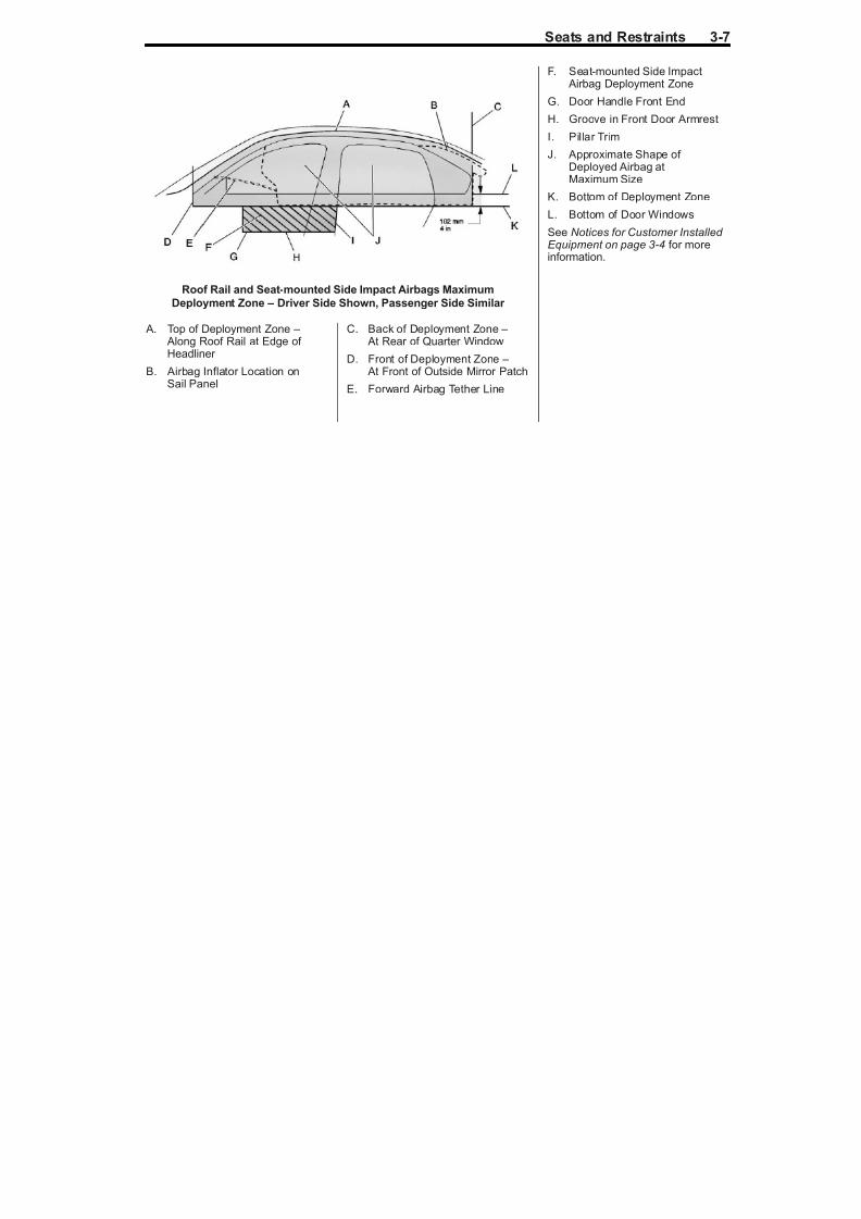
Seats and Restraints 3-7
Roof Rail and Seat‐mounted Side Impact Airbags Maximum
Deployment Zone – Driver Side Shown, Passenger Side Similar
A. Top of Deployment Zone –
Along Roof Rail at Edge of
Headliner B. Airbag Inflator Location on
Sail Panel
C. Back of Deployment Zone –
At Rear of Quarter Window
D. Front of Deployment Zone – At Front of Outside Mirror Patch
E. Forward Airbag Tether Line
F. Seat‐mounted Side Impact Airbag Deployment Zone
G. Door Handle Front End
H. Groove in Front Door ArmrestI. Pillar Trim
J. Approximate Shape of Deployed Airbag atMaximum Size
K. Bottom of Deployment Zone
L. Bottom of Door Windows
See Notices for Customer Installed Equipment on page 3
‑ 4 for more
information.

8/13/2019 2012 Impala Police-1
http://slidepdf.com/reader/full/2012-impala-police-1 14/62

8/13/2019 2012 Impala Police-1
http://slidepdf.com/reader/full/2012-impala-police-1 15/62
Instruments and Controls 5-1
Instruments andControls
Warning Lights, Gauges, andIndicators
Instrument Cluster . . . . . . . . . . . . 5-2Electronic Stability Control
(ESC) Off Light . . . . . . . . . . . . . . 5-3
Information DisplaysDriver Information
Center (DIC) . . . . . . . . . . . . . . . . . 5-4
Vehicle MessagesRide Control System
Messages . . . . . . . . . . . . . . . . . . . 5-4

8/13/2019 2012 Impala Police-1
http://slidepdf.com/reader/full/2012-impala-police-1 16/62
5-2 Instruments and Controls
Warning Lights, Gauges, and Indicators
Instrument Cluster
English Certified Cluster, Metric Similar

8/13/2019 2012 Impala Police-1
http://slidepdf.com/reader/full/2012-impala-police-1 17/62
Instruments and Controls 5-3
The words CERTIFIEDSPEEDOMETER will flash in theDriver Information Center (DIC)display for approximately
two seconds when the engine isstarted. The DIC can be set todisplay digital vehicle speed whilethe vehicle is being driven. See your owner manual for more informationon the DIC.
Electronic StabilityControl (ESC) Off Light
This light comes on briefly whilestarting the engine.
If it does not, have the vehicleserviced by your dealer. If thesystem is working normally, theindicator light then goes off.
Press and briefly hold the ESC OFFbutton to turn off the ESC system;the ESC OFF light comes on and amessage appears in the Driver Information Center (DIC).
See Ride Control System Messageson page 5 ‑ 4 for more information.
If the TCS/ESC system is off, the
system does not assist in controllingthe vehicle. Turn on the TCS/ESCsystem and the indicator lightturns off.
See Traction Control System (TCS)on page 9‑ 2 , and Electronic Stability Control (ESC) on page 9‑ 3 for moreinformation.
Performance Mode
When the ESC OFF button ispressed, th ESC OFF light comeson and PERFORMANCE MODEdisplays in the DIC.
The traction control system is still
active, but limited to drivelineprotection only. ESC is also active,but is limited to high-speed pursuitpurposes.
See the owner manual for moreinformation.

8/13/2019 2012 Impala Police-1
http://slidepdf.com/reader/full/2012-impala-police-1 18/62
5-4 Instruments and Controls
Information Displays
Driver Information
Center (DIC)Vehicle Information MenuItems
T (Vehicle Information): Pressthis button to scroll through thefollowing menu items:
Relearn Remote Key
To access this display, the vehiclemust be in P (Park). This displayallows you to match the RemoteKeyless Entry (RKE) transmitter tothe vehicle. This procedure willerase all previously learnedtransmitters. Therefore, they mustbe relearned as additionaltransmitters.
To match an RKE transmitter:
1. PressT until PRESS TO
RELEARN REMOTE KEY
displays.2. Press V. REMOTE KEY
LEARNING ACTIVE isdisplayed.
3. Press and hold the lock andunlock buttons on the firsttransmitter at the same time for about 15 seconds.
A chime will sound indicatingthat the transmitter is matched.
4. To match additional transmittersat this time, repeat Step 3.
Each vehicle can have amaximum of eight transmittersmatched to it.
5. To exit the programming mode,you must cycle the key toLOCK/OFF.
Vehicle Messages
Ride Control System
MessagesPERFORMANCE MODE
This message displays when theESC OFF button is pressed once.See Electronic Stability Control (ESC) on page 9‑ 3 for moreinformation.

8/13/2019 2012 Impala Police-1
http://slidepdf.com/reader/full/2012-impala-police-1 19/62
Lighting 6-1
Lighting
Exterior LightingExterior Lamp Controls . . . . . . . . 6-1
Exterior Lighting
Exterior Lamp Controls
Police Package and SpecialService Package
The following exterior lightingfeatures apply to vehicles first soldin the United States.
The vehicle has Daytime RunningLamps (DRL) and an AutomaticHeadlamp System (AHS). The DRL
and AHS can be turned to OFF withthe headlamp switch when thetransmission is in P (Park) and theengine is at idle. If the engine is notturned off, the DRL and AHS willremain OFF when the transmissionis placed in gear. The vehicle maybe driven with the lamps off for oneignition cycle.
The vehicle may have been builtwith SEO 9G8, DRL AND AHSDISABLE. This feature turns off DRL and AHS and requires manual
control of the exterior lighting.See your dealer to restore the DRLand AHS to normal operation.
For vehicles first sold in Canada,the DRL and AHS can be turned off if the transmission is in P (Park).See the owner manual for moreinformation.
Special Features
Police Package and SpecialService Package
The following standard features aredisabled in the Police Package andSpecial Service Package.
. Entry Lighting and Exit Lighting
. Remote Keyless Entry
Feedback: Horn Beep andLamps Flash
. Automatic Door Locking

8/13/2019 2012 Impala Police-1
http://slidepdf.com/reader/full/2012-impala-police-1 20/62
6-2 Lighting
2 NOTES

8/13/2019 2012 Impala Police-1
http://slidepdf.com/reader/full/2012-impala-police-1 21/62
Driving and Operating 9-1
Driving andOperating
Driving InformationVehicle Load Limits . . . . . . . . . . . 9-1
Starting and OperatingFast Idle System . . . . . . . . . . . . . . 9-1
Ride Control SystemsTraction Control
System (TCS) . . . . . . . . . . . . . . . 9-2
Electronic StabilityControl (ESC) . . . . . . . . . . . . . . . 9-3
TowingTrailer Towing . . . . . . . . . . . . . . . . . 9-5
Driving Information
Vehicle Load Limits
Impala police vehicles may have afull‐size spare tire. If the full‐sizespare tire is stored in the trunk of the vehicle, do not carry more than64 kg (141 lbs) in the trunk.See “Vehicle Load Limits” in theowner manual Index.
Starting andOperating
Fast Idle SystemWhile parked with the engineidling for an extended period,turn off the following factoryequipment if emergency lightingand communication equipment areoperating:
. Air Conditioner
.
Fan. Rear Window Defogger
. Factory Audio System

8/13/2019 2012 Impala Police-1
http://slidepdf.com/reader/full/2012-impala-police-1 22/62
9-2 Driving and Operating
When the automatic transmissionis in P (Park), the driver's foot is off the brake, and the emergencyequipment is turned on, the engine
rpm may increase to 1,200 rpm tokeep the electrical power of thevehicle at a steady rate. Even withthe extra power boost, the vehiclemay stall after long periods of timewith a heavy electrical load.
See “Running the Vehicle WhileParked” in the Driving andOperating section of the owner
manual for more information.
Ride Control Systems
Traction Control
System (TCS)The vehicle may have a TractionControl System (TCS) that limitswheel spin. This is especially usefulin slippery road conditions. Thesystem operates only if it sensesthat one or both of the front wheelsare spinning or beginning to losetraction. When this happens, the
system reduces engine power andmay also upshift the transmissionand apply the front brakes to limitwheel spin.
This light will flash when the TCS islimiting wheel spin.
The system may be heard or feltwhile it is working, but this isnormal.
The TCS is automatically enabled
whenever the vehicle is started. Thesystem can be turned off, but it willno longer assist in controlling thevehicle.
If cruise control is being used whenTCS begins to limit wheel spin,the cruise control will automaticallydisengage. Cruise control may bereengaged when road conditions
allow. See “Cruise Control” in theowner manual.
The TCS operates in alltransmission shift lever positions.But the system can upshift thetransmission only as high as theshift lever position chosen, souse the lower gears only whennecessary. See “ Automatic
Transmission” in the owner manual.
8/13/2019 2012 Impala Police-1
http://slidepdf.com/reader/full/2012-impala-police-1 23/62
Driving and Operating 9-3
When the system is on, this warninglight comes on and stays on if thereis a problem.
A SERVICE TRACTION CONTROLmessage also appears on the DIC.When this warning light is on, thesystem will not limit wheel spin.
Adjust your driving accordingly.See “Ride Control SystemMessages” in the owner manual.
To limit wheel spin, especially inslippery road conditions, TCSshould always be left on. But thesystem can be turned off if needed.Turn the system off if the vehiclegets stuck in sand, mud, or snow
and rocking the vehicle is required.See “If the Vehicle Is Stuck” in theowner manual.
To disable both traction control andESC, press and hold the ESC OFFbutton briefly.
When the ESC OFF button ispressed, the ESC Off light comeson and PERFORMANCE MODEdisplays in the DIC. The TCS is
still active, but limited to drivelineprotection only. ESC is also active,but is limited to high speed pursuitpurposes.
Press the ESC OFF button againto turn the system back on.The TRACTION CONTROL ONmessage will appear in the DIC.
Adding non‐dealer accessories
can affect the vehicle performance.See “ Accessories and Modifications”
in the owner manual.
Electronic StabilityControl (ESC)
Your vehicle may have an Electronic
Stability Control (ESC) systemwhich combines antilock brake,traction, and stability controlsystems and helps the driver maintain directional control of thevehicle in most driving conditions.
When you first start your vehicleand begin to drive away, the systemperforms several diagnostic checks
to ensure there are no problems.You may hear or feel the systemworking. This is normal and doesnot mean there is a problem withyour vehicle. The system shouldinitialize before the vehicle reaches32 km/h (20 mph).

8/13/2019 2012 Impala Police-1
http://slidepdf.com/reader/full/2012-impala-police-1 24/62
9-4 Driving and Operating
If the system fails to turn on or activate due to a fault, the ESC/TCSlight will be on solid, and theSERVICE STABILITRAK message
will be displayed. If the system failsto turn on or activate due to it notinitializing, the DIC will displaySTABILITRAK INITIALIZING.
For more information, see “RideControl Messages” in the owner manual.
This light will flash on the instrumentpanel cluster when the ESC systemis both on and activated.
You may also feel or hear thesystem working; this is normal.
When the light is on solid and theSERVICE STABILITRAK messageis displayed, the system will not
assist the driver in maintainingdirectional control of the vehicle. Adjust your driving accordingly.See “Ride Control Messages” in
the owner manual.The Electronic StabilityControl (ESC) system isautomatically enabled whenever you start your vehicle. To assist thedriver with vehicle directionalcontrol, especially in slippery roadconditions, you should always leavethe system on. But, you can turn
ESC off if you ever need to.If the vehicle is in cruise controlwhen the system begins to assistthe driver maintain directionalcontrol of the vehicle, the ESC/TCSlight will flash and the cruise controlwill automatically disengage. Whenroad conditions allow you to usecruise again, you may re-engagethe cruise control. See “CruiseControl” in the owner manual.
The ESC OFF button is locatedon the instrument panel.
To disable both traction controland ESC, press and hold thebutton briefly.
When the ESC OFF button ispressed, the ESC Off light comeson and PERFORMANCE MODEdisplays in the DIC. The TCS is
still active, but limited to drivelineprotection only. ESC is also active,but is limited to high speed pursuitpurposes.

8/13/2019 2012 Impala Police-1
http://slidepdf.com/reader/full/2012-impala-police-1 25/62
Driving and Operating 9-5
It is recommended to leave thesystem on for normal drivingconditions, but it may be necessaryto turn the system off if your vehicle
is stuck in sand, mud, ice, or snow, and you want to “rock” your vehicle to attempt to free it. It mayalso be necessary to turn off thesystem when driving in extremeoff-road conditions where highwheel spin is required. See “If theVehicle Is Stuck” in the owner manual.
ESC may also turn off automaticallyif it determines that a problem existswith the system. The SERVICESTABILITRAK message and the
ESC/TCS light will be on solid towarn the driver that ESC is disabledand requires service. If the problemdoes not clear after restarting thevehicle, you should see your dealer for service. See “Ride ControlSystem Messages” in the owner manual.
Adding non‐dealer accessories can
affect your vehicle performance.See “ Accessories and Modifications”
in the owner manual.
Towing
Trailer Towing
Impala police vehicles are notintended to tow a trailer.

8/13/2019 2012 Impala Police-1
http://slidepdf.com/reader/full/2012-impala-police-1 26/62
9-6 Driving and Operating
2 NOTES

8/13/2019 2012 Impala Police-1
http://slidepdf.com/reader/full/2012-impala-police-1 27/62
Vehicle Care 10-1
Vehicle Care
Vehicle Checks
Brakes . . . . . . . . . . . . . . . . . . . . . . . 10-1
Wheels and TiresTire Pressure Monitor
System . . . . . . . . . . . . . . . . . . . . . 10-1Compact Spare Tire . . . . . . . . . 10-2Full-Size Spare Tire
(SEO N81) . . . . . . . . . . . . . . . . . 10-3
Vehicle Checks
Brakes
All Impala police vehicles have the Antilock Brake System (ABS).Many of the components of thebrake system used on the Impalapolice vehicle are unique to thevehicle. Before doing any servicework, consult the appropriateservice manual.
See “Brakes” in the owner manual
for additional information on thebrake system.
Wheels and Tires
Tire Pressure Monitor
SystemThe Impala full-size spare includesa sensor for the Tire PressureMonitor System (TPMS). Thecompact spare tire/wheel, which isstandard with the Impala PolicePackage, does not include a TPMSsensor. The TPMS will not monitor or display the spare tire air pressure
until the tire/wheel is installed at oneof the four tire/wheel positions onthe vehicle.
Once installed, the spare tiresensor code must be matched tothe new position on the vehicle.See “Tire Pressure Monitor SystemOperation”in the Owner ManualIndex for information aboutmatching the spare tire tothe TPMS.

8/13/2019 2012 Impala Police-1
http://slidepdf.com/reader/full/2012-impala-police-1 28/62
10-2 Vehicle Care
Compact Spare Tire
A. Retainer
B. Retainer Bracket
C. Wheel Wrench
D. Jack
E. Jack Container
F. Compact Spare Tire
G. Bolt Screw
Impala police vehicles may beequipped with a 17-inch compactspare tire instead of a full-sizespare tire.
Refer to the following diagram asa guide for storing the compactspare tire in the trunk. For moreinformation on spare tire storageand changing a flat tire, see “TireChanging” in the Vehicle Caresection of the owner manual.
Compact Spare Tire
A. Retainer
B. Retainer Bracket

8/13/2019 2012 Impala Police-1
http://slidepdf.com/reader/full/2012-impala-police-1 29/62
Vehicle Care 10-3
C. Wheel Wrench
D. Jack
E. Jack Container
F. Compact Spare TireG. Bolt Screw
Full-Size Spare Tire(SEO N81)
Impala police vehicles may beequipped with a full-size spare tire.When the full-size spare tire optionis ordered, the tire is equipped witha vinyl cover and a surroundingtrunk mat. See Vehicle Load Limitson page 9‑ 1 for more information.
Refer to the following diagram asa guide for storing the full-size
spare tire in the trunk. For moreinformation on spare tire storageand changing a flat tire, see “TireChanging” in the Vehicle Caresection of your owner manual.
Full-Size Spare Tire
A. Retainer
B. Full-Size Spare Tire
C. Extension Bolt Screw
D. Wheel Wrench
E. Jack
F. Foam Holder
G. Bolt Screw
10 4 V hi l C

8/13/2019 2012 Impala Police-1
http://slidepdf.com/reader/full/2012-impala-police-1 30/62
10-4 Vehicle Care
2 NOTES
S i d M i t 11 1

8/13/2019 2012 Impala Police-1
http://slidepdf.com/reader/full/2012-impala-police-1 31/62
Service and Maintenance 11-1
Service andMaintenance
Recommended Fluids,Lubricants, and Parts
Maintenance ReplacementParts . . . . . . . . . . . . . . . . . . . . . . . 11-2
11 2 S i d M i t

8/13/2019 2012 Impala Police-1
http://slidepdf.com/reader/full/2012-impala-police-1 32/62
11-2 Service and Maintenance
Recommended Fluids, Lubricants, and Parts
Maintenance Replacement Parts
Replacement parts identified below by name, part number, or specification can be obtained from your dealer.
Maintenance Replacement Parts
Part GM Part Number ACDelco Part Number
Engine Air Cleaner/Filter 10350737 A2962C
Engine Oil Filter 12600224 PF48
Passenger Compartment Air Filter 15284938 CF132
Spark Plugs 12622561 41‐
109Wiper Blades
Driver Side ‐ 55.0 cm (21.7 in) 15941731 —
Passenger Side ‐ 55.0 cm (21.7 in) 15941732 —
Special Equipment Options 15 1

8/13/2019 2012 Impala Police-1
http://slidepdf.com/reader/full/2012-impala-police-1 33/62
Special Equipment Options 15-1
Special EquipmentOptions
SEO Standard OptionsSEO Standard Options -
Police Package and SpecialService Package . . . . . . . . . . . 15-2
Power Steering/Engine OilCooling System . . . . . . . . . . . . 1 5-2
Trunk Ground Stud . . . . . . . . . . 15-3Wiring Provisions for 12-Volt
Battery Power Supply . . . . . . 15-4
Auxiliary Battery Power Junction Blocks .. . . . . . . . . . . 15-8
Heavy Duty CoolingS y s t e m . . . . . . . . . . . . . . . . . . . 1 5 - 1 0
Radios . . . . . . . . . . . . . . . . . . . . . 15-10Seats . . . . . . . . . . . . . . . . . . . . . . . 15-10Trunk Mat . . . . . . . . . . . . . . . . . . 15-10
SEO Available OptionsSEO Available Options -
Police Package and SpecialService Package .. . . . . . . . . 15-11
Auxiliary Dome Lamp -SEO 6C7 . . . . . . . . . . . . . . . . . . 15-11Dome Lamp Inoperative
Function - SEO 7Y6 . . . . . . . 15-12Inoperative Rear Door
Handles - SEO 6B2 . . . . . . . 15-12Inoperative Rear Door
Locks - SEO 6N6 . . . . . . . . . 15-12Exterior Lamp Emergency
Flashing System -
SEO 6J7 . . . . . . . . . . . . . . . . . . 1 5-12Heavy Duty Floor
Covering - SEO 6A3 . . . . . . 15-15Ignition Control Trunk
Release - SEO A98 . . . . . . . 15-15Rear Panel Lamps -
SEO 6J6 . . . . . . . . . . . . . . . . . . 1 5-15Rear Windows
Inoperative - SEO 6N5 . . . . 15-15
Spotlamp - SEO 7X6 . . . . . . . 15-15Wiring Provisions for Vehicle
Grille Lamps, Flasher andSpeaker/Siren -SEO 6J3 . . . . . . . . . . . . . . . . . . 15-16
Spotlamp Provisions -SEO 7X8 . . . . . . . . . . . . . . . . . . 15-18
Spotlamp Provisions -SEO 7X9 . . . . . . . . . . . . . . . . . . 15-18
Spotlamps - SEO 7X7 . . . . . . 15-18Trunk Lid Warning
Lamps - SEO T53 . . . . . . . . . 15-18Wiring Provisions for
Horn/Siren Circuit -
SEO 6J4 . . . . . . . . . . . . . . . . . . 15-19Wiring Provisions for
Roof-Mounted Accessories - SEO 6F5 . . . 15-21
Wiring Provisions FrontSpeakers - SEO WX7 . . . . . 15-23
Wiring Provisions Rear Coaxial Cable -SEO 6C8 . . . . . . . . . . . . . . . . . 15-26
15 2 Special Equipment Options

8/13/2019 2012 Impala Police-1
http://slidepdf.com/reader/full/2012-impala-police-1 34/62
15-2 Special Equipment Options
SEO StandardOptions
SEO Standard Options -Police Package andSpecial Service Package
Notice: GM cannot beresponsible for any changesmade to the vehicle. Have allelectrical and body modificationsperformed by experiencedtechnicians.
. Be sure that any modifiedor added wiring will workproperly with your vehicle'swiring system.
. See that all wiring is properlyprotected by fuses, and notcausing an overload toconnectors and components.
. Do not route wiring inareas of the vehicle wheretemperatures can be high or where wiring may be cut,pinched, or rubbed.
. See that all added wiring isof the same or larger gaugethan the wire it is beingattached to for proper fuseprotection.
. Be sure that all holes drilledin the body are properlysealed and corrosionprotected. See that thevehicle's wiring harnesses,piping, and other components have not beendisplaced or damaged duringcustomer installations of
equipment and wiring.. Do not route wiring or
equipment which couldinterfere with roof ‐mountedside impact airbags.
Notice: Overloading the vehicle'selectrical system may damageyour vehicle's accessories.Do not overload the vehicle'ssystem by having unnecessaryaccessories on at the same time.
Power Steering/EngineOil Cooling System
A. Engine Oil Cooler
B. Power Steering Cooler
C. Transmission Fluid Cooler
Special Equipment Options 15-3
8/13/2019 2012 Impala Police-1
http://slidepdf.com/reader/full/2012-impala-police-1 35/62
Special Equipment Options 15-3
Your Impala police vehicle isequipped with auxiliary fin-typeair-to-oil coolers mounted in front of the engine coolant radiator.
The engine oil and power steeringfluid coolers are mounted on acommon frame to the right of center.The transmission fluid cooler ismounted separately to the left of center and provides fluid cooling inaddition to the coolant radiator end-tank cooling.
Trunk Ground Stud
A 10 mm ground stud can be foundin the trunk on the passenger sideof the vehicle. The stud is locatedabove the trunk auxiliary junctionblock. See “Trunk Auxiliary BatteryPower Junction Block” that followsfor more information on location.
A 10 mm flanged hex nut groundsthe 10 mm bolt to the vehicle.Recommended torque for theflanged nut is 35 N·m (26 lb ft), plusor minus 5 N·m (4 lb ft). A 10 mmhex nut is provided for customer ground termination. Recommendedtorque for the terminal connectionnut is 10 N·m (7.3 lb ft), plus or minus 1.3 N·m (1 lb ft).
15-4 Special Equipment Options

8/13/2019 2012 Impala Police-1
http://slidepdf.com/reader/full/2012-impala-police-1 36/62
15-4 Special Equipment Options
Wiring Provisions for 12-Volt Battery Power Supply
Special Equipment Options 15-5

8/13/2019 2012 Impala Police-1
http://slidepdf.com/reader/full/2012-impala-police-1 37/62
Special Equipment Options 15 5
15-6 Special Equipment Options

8/13/2019 2012 Impala Police-1
http://slidepdf.com/reader/full/2012-impala-police-1 38/62
15 6 Special Equipment Options
Battery power is supplied throughtwo fusible links, one 50 amp andone 65 amp, to three circuitbreakers and two control relayslocated in the relay center abovethe accelerator pedal. For locationinformation, see “Servicing Relaysand Circuit Breakers” in the Index. A 50 amp circuit breaker feedspower directly from the 50 ampfusible link through a 5.0 mm²(10 gauge) blunt cut wire.Two 30 amp circuit breakerssupply power from the 65 amp
fusible link through the contactsof the control relays to 3.0 mm²(12 gauge) blunt cut wires.
The blunt cut leads are part of a1.5 m (5 ft) loop of wire coiledunder the instrument panel in thefront passenger side footwell.
Each relay is operated by an0.8 mm² (18 gauge) blunt cut, lightor dark blue control lead includedin the 1.5 m (5 ft) coil under theinstrument panel. An 8.0 mm²(8 gauge) ground lead is alsoprovided in the 1.5 m (5 ft) coil.The total current available throughthe 12-volt power supply is110 amps (1320 watts).
Blunt cut ignition controlled power and signal circuits are also includedin the following 1.5 m (5 ft) rightfoot loop:
.
A yellow, 0.5 mm² (20 gauge)10 amp fused circuit, Hot in ACC/ACCESSORY, ON/RUN or RAP (Retained AccessoryPower). The fuse for this circuitis labeled “RAP” and is locatedin the fuse block in the frontpassenger side instrumentpanel.
.
A pink, 0.5 mm² (20 gauge)10 amp fused circuit, Hot inSTART and ON/RUN. The fusefor this circuit is labeled “PWRDROP/CRANK” and is located inthe underhood fuse block in theengine compartment.
Special Equipment Options 15-7

8/13/2019 2012 Impala Police-1
http://slidepdf.com/reader/full/2012-impala-police-1 39/62
Spec a qu p e t Opt o s 5
. A yellow/black, 0.5 mm²(20 gauge) transaxle park signalfrom the Body Control Module(BCM). The circuit provides aswitched power when the
transaxle is not in PARK (P)and the engine is running.The electrical load attached tothe park circuit must not exceed0.5 amps and is meant to driveone relay coil.
. A brown, 0.35 mm² (22 gauge)vehicle speed signal(4,000 pulses/mile) from the
ABS module. Connect onlyhigh impedance load.
Servicing Relays and CircuitBreakers
The following information shows youwhere the relays and circuit
breakers are located in the FuseBlock‐SEO.
A. Instrument Panel Carrier
B. Relay Center for CircuitBreakers and Control Relay
C. Instrument Panel HarnessBranch
Enlarged View of the
SEO Fuse Block
A. Relays and Circuit Breakers
B. Front of the Vehicle
C. Floor of the Vehicle
15-8 Special Equipment Options

8/13/2019 2012 Impala Police-1
http://slidepdf.com/reader/full/2012-impala-police-1 40/62
p q p p
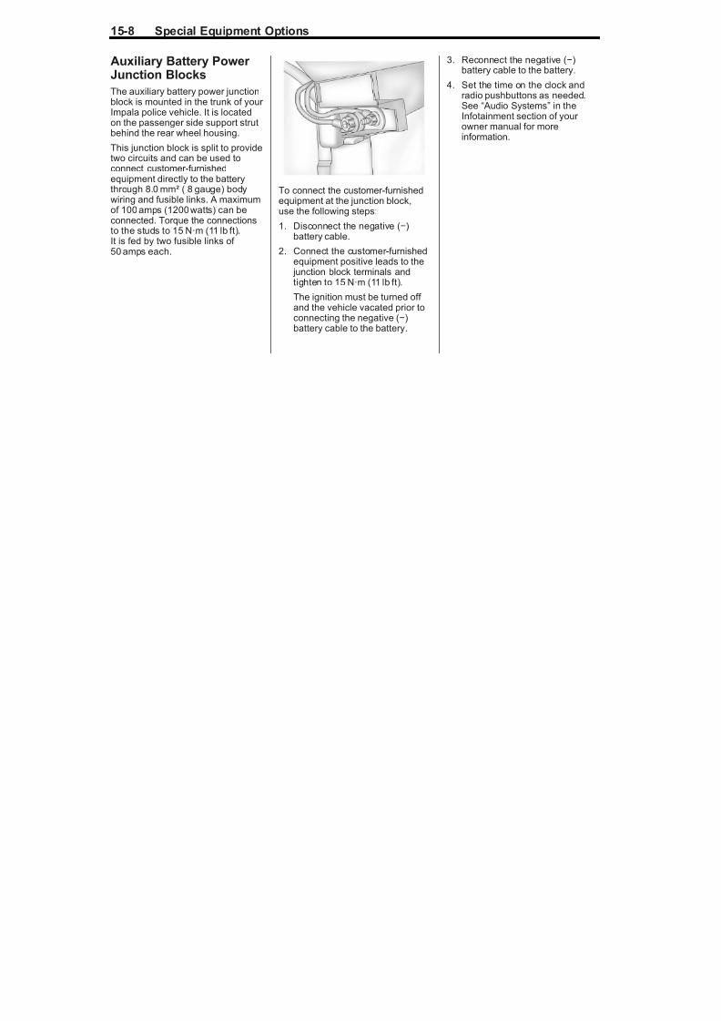
Auxiliary Battery Power Junction Blocks
The auxiliary battery power junctionblock is mounted in the trunk of your Impala police vehicle. It is locatedon the passenger side support strutbehind the rear wheel housing.
This junction block is split to providetwo circuits and can be used toconnect customer-furnishedequipment directly to the batterythrough 8.0 mm² ( 8 gauge) bodywiring and fusible links. A maximum
of 100 amps (1200 watts) can beconnected. Torque the connectionsto the studs to 15 N·m (11 lb ft).It is fed by two fusible links of 50 amps each.
To connect the customer-furnishedequipment at the junction block,use the following steps:
1. Disconnect the negative (−)battery cable.
2. Connect the customer ‐furnishedequipment positive leads to the junction block terminals andtighten to 15 N·m (11 lb ft).
The ignition must be turned off
and the vehicle vacated prior toconnecting the negative (−)battery cable to the battery.
3. Reconnect the negative (−)battery cable to the battery.
4. Set the time on the clock andradio pushbuttons as needed.
See “ Audio Systems”
in theInfotainment section of your owner manual for moreinformation.
Special Equipment Options 15-9

8/13/2019 2012 Impala Police-1
http://slidepdf.com/reader/full/2012-impala-police-1 41/62
p q p p
Wiring Diagram for Trunk Auxiliary Battery Power Junction Block
15-10 Special Equipment Options

8/13/2019 2012 Impala Police-1
http://slidepdf.com/reader/full/2012-impala-police-1 42/62
Heavy Duty CoolingSystem
A high capacity radiator and fanreplace the standard coolingsystem. Refer to the owner manualfor more information on the coolingsystem.
Radios
Chime Level Adjustment
Impala police vehicles are equippedwith a radio that provides an AM-FM
stereo with a CD player. The radioproduces the required warningchimes for the vehicle. The volumelevel of the chimes can be adjustedto be louder, but cannot beturned off.
The sound for the warning chimesis directed to the left front door speaker. When SEO WX7 (wiringprovisions for the front speakers) isinstalled, the sound is directed to
the left rear speaker.
See “Climate Controls” and “ AudioSystems” in your owner's manual toadjust the chime volume or contactyour dealer for assistance.
Radio Suppression
Impala police vehicles are equippedwith spark plugs and spark plug
wires designed to reduce radiointerference noise levels which mayaffect communication equipment,including operating frequencies inthe 38 MHz to 58 MHz range.
Seats
Impala SEO 9C1 police vehicles areequipped with high‐density foamfront seats that have security panels
in the seatbacks and a high‐densityfoam rear seat cushion andseatback.
Trunk Mat
A heavy duty vinyl mat covers thetrunk floor in vehicles equippedwith either a compact or full‐sizespare tire.
Special Equipment Options 15-11

8/13/2019 2012 Impala Police-1
http://slidepdf.com/reader/full/2012-impala-police-1 43/62
SEO AvailableOptions
SEO Available Options -Police Package andSpecial Service Package
Notice: GM cannot beresponsible for any changesmade to the vehicle. Have allelectrical and body modificationsperformed by experiencedtechnicians.
. Be sure that any modified or added wiring will workproperly with your vehicle'swiring system.
. See that all wiring is properlyprotected by fuses, and notcausing an overload toconnectors and components.
. Do not route wiring inareas of the vehicle wheretemperatures can be high or where wiring may be cut,pinched, or rubbed.
. See that all added wiring isof the same or larger gaugethan the wire it is beingattached to for proper fuseprotection.
. Be sure that all holes drilledin the body are properlysealed and corrosionprotected. See that thevehicle's wiring harnesses,piping, and other components have not beendisplaced or damaged duringcustomer installations of equipment and wiring.
. Do not route wiring or equipment which couldinterfere with roof ‐mounted
side impact airbags.
Auxiliary DomeLamp - SEO 6C7
The auxiliary dome lamp is locatedon the headliner between the driver and the front passenger seatingpositions. The button for this lamp islocated at the rear base of the lamp.The lamp is wired independently.To operate the lamp, press thebutton. To turn the lamp off, pressthe button again.
15-12 Special Equipment Options

8/13/2019 2012 Impala Police-1
http://slidepdf.com/reader/full/2012-impala-police-1 44/62
Dome Lamp InoperativeFunction - SEO 7Y6
This feature makes the dome lampinoperative when a door is opened.The dome and courtesy lamps canonly be controlled using the domelamp button on the overheadconsole.
Inoperative Rear Door Handles - SEO 6B2
This feature makes the rear door handles inoperative. When the
feature is enabled, the inside rear door handles are disconnected andthe rear doors can only be openedfrom the outside.
Inoperative Rear Door Locks - SEO 6N6
This feature makes the rear door
locks inoperative. When the featureis enabled, the rear door lockswitches are disconnected and therear doors can only be locked or unlocked from the driver's door lockswitch.
Exterior LampEmergency FlashingSystem - SEO 6J7
SEO 6J7 provides a high-beamheadlamps flashing module, rear lamps flashing, and control wire for a customer-furnished switch to turnthe module on or off. The flasher control wire is coiled in thepassenger side footwell under theinstrument panel. This control leadmay be combined with the interior wiring leads for SEO 6J3 when that
option is ordered with SEO 6J7.
Special Equipment Options 15-13

8/13/2019 2012 Impala Police-1
http://slidepdf.com/reader/full/2012-impala-police-1 45/62
The headlamps flashing moduleis located at the inboard end of the passenger side headlampsassembly. The headlamps flashingmodule is activated by the
application of 12 volts to a red/whitewire coiled in the passenger sidefootwell. When activated, the driver and passenger side high-beamheadlamps will flash alternately at2.4 flashes per second.
During daylight conditions, theDaytime Running Lamps (DRL)are automatically turned off
whenever the headlampsflasher module is activated.
During nighttime conditions, thelow-beam headlamps turn onautomatically while the high-beamheadlamps flash. Turning on thehigh-beam headlamps manually
with the turn signal/multifunctionlever will override the flashingmodule and the high-beamheadlamps will operatecontinuously.
A fuse labeled HDLP MDL protectsthe flasher module circuit. This fuseis located in the underhood fuseblock in the engine compartment on
the passenger side of the vehicle.See “Fuses and Circuit Breakers”
in the Vehicle Care section of your Impala owner manual for moreinformation.
When the headlamps flashingmodule is turned on, the modulesends a signal to the Body ControlModule (BCM). The BCM alternatelyflashes the stop lamps and backup
lamps. Depressing the brake pedalwill override the stop lamp flashingand placing the transaxle in reversewill override the backup lampflashing.
When it is dark outside, thetaillamps will turn on automatically.The Center High-Mounted Stoplamp(CHMSL) will not flash and will
operate only when the regular brakepedal is pressed.
15-14 Special Equipment Options

8/13/2019 2012 Impala Police-1
http://slidepdf.com/reader/full/2012-impala-police-1 46/62
Forward Lamp Harness In-Line Connector for use with Headlamps Flasher Module, Option 6J7
Special Equipment Options 15-15

8/13/2019 2012 Impala Police-1
http://slidepdf.com/reader/full/2012-impala-police-1 47/62
The connector is located on theback of the passenger side of thebumper beam.
Heavy Duty Floor Covering - SEO 6A3
Impala police vehicles are equippedwith carpet and carpeted floor mats.Optional heavy floor coveringmay replace the carpeting andfloor mats.
Ignition Control Trunk
Release - SEO A98Impala police vehicles are equippedwith an electric trunk release whichoperates when the vehicle's ignitionis in LOCK/OFF. This feature can bechanged, however, to operate onlywhen the vehicle's ignition is inON/RUN. To enable this feature onyour vehicle, contact your dealer for
assistance.
Rear Panel Lamps -SEO 6J6
Two 10 cm (4 in) red single facedlamps are mounted behind therear seatback to be viewed throughthe rear window. The lamps workas auxiliary turn signal lamps,stoplamps, and hazard warningflashers. The wire to each lamp isextended to a loop with yellow (left)and green (right) wires coiled inthe passenger side footwell.
These loops allow customer installation of an in-line switch ineach lamp circuit to disable theauxiliary lamp feature.
Rear WindowsInoperative - SEO 6N5
This feature makes the rear windowswitches inoperative. While thefeature is enabled, the rear windowswitches are disconnected and therear windows can only be operatedfrom the driver's window switch.
Spotlamp - SEO 7X6
This option includes onepillar-mounted driver side halogenspotlamp. The spotlamp has a fuselocated in the passenger sideunderhood fuse block.
15-16 Special Equipment Options

8/13/2019 2012 Impala Police-1
http://slidepdf.com/reader/full/2012-impala-police-1 48/62
Wiring Provisions for Vehicle Grille Lamps,Flasher and Speaker/ Siren - SEO 6J3
Alternating Signal Flasher
A. Blunt cut ends for theCustomer-FurnishedGrille Lamps andCustomer-FurnishedSiren/Speaker
B. Control Wires from In-LineConnector in ForwardLamp Harness for Customer-Furnished GrilleLamps and Speaker
The SEO 6J3 wiring provision optionconsists of a 1.5 m (5 ft) wiringharness coiled underneath theinstrument panel on the passenger side. The wiring circuits are routed
from underneath the instrumentpanel to a 30 cm (1 ft) coil securedin the area behind the grille.There are four 1.0 mm² (16 gauge)wires for connecting to the grillelights (GRY, TAN) and siren speaker (LT BU, LT GN).
The SEO 6J3 wiring provision alsoincludes one 0.8 mm² (18 gauge)
control wire for the SEO 6J7 exterior lamps emergency flashing system.
When option SEO 6J7 is installedwithout option SEO 6J3, only thedark green/red control wire isprovided for connection tocustomer-furnished 12-voltswitching to turn the emergencyflashing system on or off.
Special Equipment Options 15-17

8/13/2019 2012 Impala Police-1
http://slidepdf.com/reader/full/2012-impala-police-1 49/62
Wiring Diagram for SEO 6J3 and SEO 6J7
15-18 Special Equipment Options
8/13/2019 2012 Impala Police-1
http://slidepdf.com/reader/full/2012-impala-police-1 50/62
Spotlamp Provisions -SEO 7X8
This option includes a provisionfor the installation of a driver side
pillar-mounted spotlamp. Theprovision includes a hole in the A pillar for spotlamp shaft routing,mounting bracket, and a power connector. The spotlamp wiring ispowered by a fuse located in thepassenger side underhood fuseblock.
Spotlamp Provisions -SEO 7X9
This option includes provisionsfor the installation of driver andpassenger side pillar-mountedspotlamps. The provision includesa hole in the A pillar for spotlampshaft routing, mounting bracket, anda power connector. The spotlamp
wiring is powered by fuses that arelocated in the passenger sideunderhood fuse block.
Spotlamps - SEO 7X7
SEO 7X7 includes a driver and apassenger side spotlamp.
The spotlamp fuses are located inthe passenger side underhoodfuse block. See “Fuses and CircuitBreakers” in the Vehicle Caresection of your Impala owner manual for more information.
For spotlamp bulb replacementprocedures, see the appropriatesection of the service manual.
Trunk Lid WarningLamps - SEO T53
Two 10 cm (4 in) single faced lampsare mounted to the inside of thetrunk lid. The lamps work while thetrunk lid is opened. They are wiredto flash alternately through a flasher located at the right front corner of the trunk opening.
Special Equipment Options 15-19

8/13/2019 2012 Impala Police-1
http://slidepdf.com/reader/full/2012-impala-police-1 51/62
Wiring Provisions for Horn/Siren Circuit -SEO 6J4
This provision permits customer connection of a switch to selecteither horn or siren operation whenthe horn pad is pressed.
A 0.35 mm² (22 gauge) wire isconnected to an in-line connector inthe horn circuit of the instrumentpanel harness under the instrumentpanel. The end of this harness
extension is in a 1.5 m (5 ft) loop of wire coiled under the instrumentpanel.
15-20 Special Equipment Options

8/13/2019 2012 Impala Police-1
http://slidepdf.com/reader/full/2012-impala-police-1 52/62
Wiring Diagram for SEO 6J4 Inline Connector

8/13/2019 2012 Impala Police-1
http://slidepdf.com/reader/full/2012-impala-police-1 53/62
15-22 Special Equipment Options

8/13/2019 2012 Impala Police-1
http://slidepdf.com/reader/full/2012-impala-police-1 54/62
Wiring Diagram for SEO 6F5
Special Equipment Options 15-23

8/13/2019 2012 Impala Police-1
http://slidepdf.com/reader/full/2012-impala-police-1 55/62
Option 6F5 is a universal wiringharness for roof-mountedequipment. The harness is routedfrom a 1.5 m (5 ft) coil of wire inthe passenger side footwell to a
connector on the passenger side of the trunk.
When the SEO 6B7 (center hole) isordered, two color-coded 5.0 mm²(10 gauge) wires extend 60 cm(24 in) through a grommetapproximately 74 cm (30 in) behindthe top of the windshield at thecenter of the roof.
When SEO 6J5 (passenger sidehole) is ordered, two color ‐coded5.0 mm² (10‐gauge) wires extend60 cm (24 in) through a grommetapproximately 74 cm (30 in) behindthe top of the windshield and 15 cm(6 in) inboard from the passenger side longitudinal roof joint.
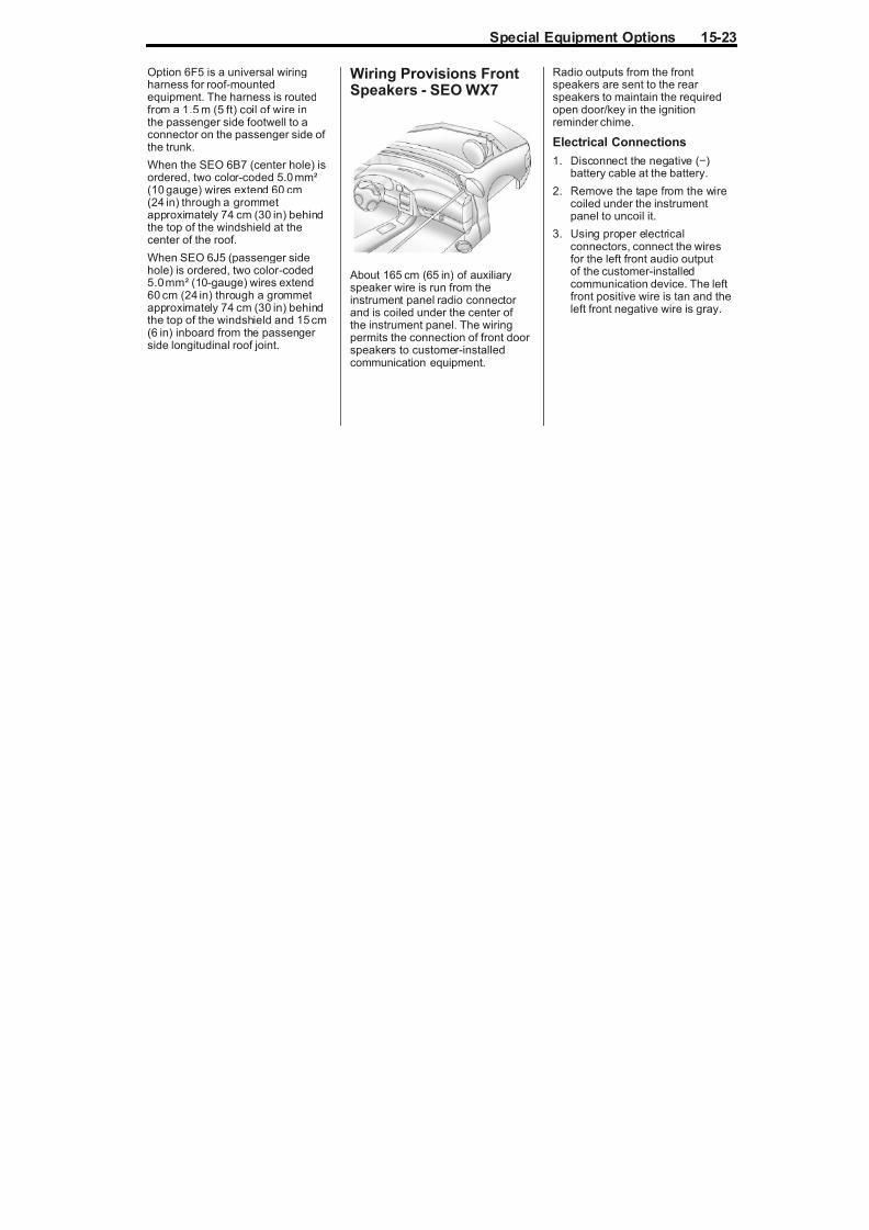
Wiring Provisions FrontSpeakers - SEO WX7
About 165 cm (65 in) of auxiliaryspeaker wire is run from theinstrument panel radio connector and is coiled under the center of the instrument panel. The wiringpermits the connection of front door speakers to customer-installedcommunication equipment.
Radio outputs from the frontspeakers are sent to the rear speakers to maintain the requiredopen door/key in the ignitionreminder chime.
Electrical Connections
1. Disconnect the negative (−)battery cable at the battery.
2. Remove the tape from the wirecoiled under the instrumentpanel to uncoil it.
3. Using proper electricalconnectors, connect the wiresfor the left front audio outputof the customer-installedcommunication device. The leftfront positive wire is tan and theleft front negative wire is gray.
15-24 Special Equipment Options

8/13/2019 2012 Impala Police-1
http://slidepdf.com/reader/full/2012-impala-police-1 56/62
4. Using proper electricalconnectors, connect the wiresfor the right front audio outputof the customer-installedcommunication device. The right
front positive wire is light greenand the right front negative wireis dark green. The electricalimpedance of each speaker installed is 10 ohms.
Notice: Overloading the vehicle'selectrical system may damageyour vehicle's accessories.Do not overload the vehicle's
system by having unnecessaryaccessories on at the same time.
5. The ignition must be turned off and the vehicle must be vacatedprior to attaching the cable to thebattery. Connect the negative (−)battery cable to the battery and
tighten the bolt to 15 N·m(11 lb ft).
6. Set the time on the clock andradio pushbuttons as needed.See “ Audio Systems” in theInfotainment section of your owner manual for moreinformation.

8/13/2019 2012 Impala Police-1
http://slidepdf.com/reader/full/2012-impala-police-1 57/62
15-26 Special Equipment Options

8/13/2019 2012 Impala Police-1
http://slidepdf.com/reader/full/2012-impala-police-1 58/62
Wiring Provisions Rear Coaxial Cable - SEO 6C8
About 240 cm (95 in) of RG58coaxial radio antenna cable is runfrom the roof panel just rear of thecenter dome lamp and coiled inthe trunk to reach either corner.The cable permits the connection of customer-installed communicationequipment.
INDEX i-1

8/13/2019 2012 Impala Police-1
http://slidepdf.com/reader/full/2012-impala-police-1 59/62
A Accessories, Wiring
Provisions for
Roof-Mounted - SEO 6F5 . . . 15-21
AirbagsDeployment Diagrams . . . . . . . . . 3-5
Questions and Answers
About Airbags and
Specialty Law
Enforcement Vehicles . . . . . . . . 3-1
Auxiliary
Available Option . . . . . . . . . . . . . .15-8
Auxiliary Battery Power
Junction Blocks, AvailableOption . . . . . . . . . . . . . . . . . . . . . . . . 15-8
Auxiliary Dome Lamp
SEO - 6C7 . . . . . . . . . . . . . . . . . . 15-11
BBattery
Power Junction Blocks . . . . . . .15-8
Wiring Provisions for
12-Volt Power Supply . . . . . . .15-4
Brakes . . . . . . . . . . . . . . . . . . . . . . . . . 10-1
CCable, Wiring Provisions
for Coaxial Cable -
SEO 6C8 . . . . . . . . . . . . . . . . . . . .15-26
Canadian Vehicle Owners . . . . . . . . . iiCircuit
Wiring Provisions for
Horn/Siren - SEO 6J4 . . . . . 15-19
Cluster, Instrument . . . . . . . . . . . . . 5-2
Compact Spare Tire . . . . . . . . . . . 10-2
Cooling
Heavy Duty System . . . . . . . . 15-10
Customer-installed
Equipment, Notices . . . . . . . . . . . 3-4
DDeployment Diagrams . . . . . . . . . . 3-5
Dome Lamp Inoperative
Function - SEO 7Y6 . . . . . . . . . 15-12
Driver Information
Center (DIC) . . . . . . . . . . . . . . . . . . 5-4
Driving
Vehicle Load Limits . . . . . . . . . . . . 9-1
EElectronic Stability Control . . . . . . 9-3
Electronic Stability Control
(ESC) Off Light . . . . . . . . . . . . . . . . 5-3
EngineOil Cooling System and
Power Steering . . . . . . . . . . . . . .15-2
Exterior Lamp Controls . . . . . . . . . 6-1
Exterior Lamp Emergency
Flashing System -
SEO 6J7 . . . . . . . . . . . . . . . . . . . . 15-12
FFast Idle System . . . . . . . . . . . . . . . . 9-1Flasher, Wiring
Provisions - SEO 6J3 . . . . . . . 15-16
Floor Covering
Heavy Duty - SEO 6A3 . . . . . 15-15
Full-Size Spare Tire . . . . . . . . . . . 10-3
i-2 INDEX

8/13/2019 2012 Impala Police-1
http://slidepdf.com/reader/full/2012-impala-police-1 60/62
HHeavy Duty Cooling
System . . . . . . . . . . . . . . . . . . . . . . 15-10
Heavy Duty Floor
Covering - SEO 6A3 . . . . . . . . 15-15Horn/Siren, Wiring
Provisions - SEO 6J4 . . . . . . . 15-19
IIdle System
Fast . . . . . . . . . . . . . . . . . . . . . . . . . . . 9-1
Ignition Control Trunk
Release - SEO A98 . . . . . . . . . 15-15
Inoperative Rear Door Handles- SEO 6B2 . . . . . . . . . . 15-12
Inoperative Rear Door
Locks - SEO 6N6 . . . . . . . . . . . 15-12
Instrument Cluster . . . . . . . . . . . . . . 5-2
Introduction . . . . . . . . . . . . . . . . . . . . . . . .ii
K
KeysSingle Key Random Code
System . . . . . . . . . . . . . . . . . . . . . . . 2-1
LLamp
Auxiliary Dome,
SEO - 6C7 . . . . . . . . . . . . . . . . .15-11
LampsExterior Controls . . . . . . . . . . . . . . . 6-1
Exterior Emergency
Flashing System -
SEO 6J7 . . . . . . . . . . . . . . . . . . 15-12
Rear Panel - SEO 6J6 . . . . . . 15-15
Trunk Lid Warning -
SEO T53 . . . . . . . . . . . . . . . . . . 15-18
Vehicle Grille Wiring
Provisions - SEO 6J3 . . . . . 15-16Light
Electronic Stability Control
(ESC), Off . . . . . . . . . . . . . . . . . . . . 5-3
MMat, Trunk . . . . . . . . . . . . . . . . . . . . 15-10
Messages
Ride Control System . . . . . . . . . . . 5-4
Monitor System, Tire
Pressure . . . . . . . . . . . . . . . . . . . . . 10-1
NNotices for
Customer-installed
Equipment . . . . . . . . . . . . . . . . . . . . 3-4
PPolice Package
SEO Available Options . . . . . .15-11
Police Package and
Special Service Package,
SEO Standard Options . . . . . . . 15-2
Power Steering/Engine Oil
Cooling System . . . . . . . . . . . . . . 15-2
QQuestions and Answers
About Airbags and
Specialty Law Enforcement
Vehicles . . . . . . . . . . . . . . . . . . . . . . . 3-1
INDEX i-3
S O S O S

8/13/2019 2012 Impala Police-1
http://slidepdf.com/reader/full/2012-impala-police-1 61/62
RRadios . . . . . . . . . . . . . . . . . . . . . . . .15-10
Rear Panel Lamps -
SEO 6J6 . . . . . . . . . . . . . . . . . . . . 15-15
Rear WindowsInoperative - SEO 6N5 . . . . . . 15-15
Replacement Parts
Maintenance . . . . . . . . . . . . . . . . . .11-2
Ride Control Systems . . . . . . . . . . 9-3
Electronic Stability (ESC) . . . . . . 9-3
Messages . . . . . . . . . . . . . . . . . . . . . 5-4
Roof-Mounted
Accessories, Wiring
Provisions - SEO 6F5 . . . . . . . 15-21
SSafety Belts
Questions and Answers
About Airbags and
Specialty Law
Enforcement Vehicles . . . . . . . . 3-1
Seats . . . . . . . . . . . . . . . . . . . . . . . . . 15-10
SEO Available OptionsPolice Package . . . . . . . . . . . . . .15-11
SEO Standard Options
Police Package and
Special Service Package . . . .15-2
Spare Tire
Compact . . . . . . . . . . . . . . . . . . . . . .10-2
Speaker/Siren, WiringProvisions - SEO 6J3 . . . . . . . 15-16
Speakers
Wiring Provisions,
Front - SEO WX7 . . . . . . . . . 15-23
Special Equipment Options
Dome Lamp Inoperative
Function - SEO 7Y6 . . . . . . . 15-12
Heavy Duty Floor
Covering - SEO 6A3 . . . . . . 15-15
Ignition Control Trunk
Release - SEO A98 . . . . . . . 15-15
Spotlamp Provisions -
SEO 7X8 . . . . . . . . . . . . . . . . . . 15-18
Spotlamp Provisions -
SEO 7X9 . . . . . . . . . . . . . . . . . . 15-18
Specific Cylinder Unit for
Single Key - Random
Code System . . . . . . . . . . . . . . . . . 2-1
Spotlamp
SEO 7X6 . . . . . . . . . . . . . . . . . . . 15-15
Spotlamp Provisions -
SEO 7X8 . . . . . . . . . . . . . . . . . . . . 15-18
Spotlamps
SEO 7X7, AvailableOption . . . . . . . . . . . . . . . . . . . . . 15-18
Supplement
Using . . . . . . . . . . . . . . . . . . . . . . . . . . . .iii
System
Heavy Duty Cooling . . . . . . . . 15-10
T
TiresCompact Spare . . . . . . . . . . . . . . .10-2
Full-Size Spare . . . . . . . . . . . . . . .10-3
Pressure Monitor System . . . . .10-1
Towing
Trailer . . . . . . . . . . . . . . . . . . . . . . . . . 9-5
Traction
Control System (TCS) . . . . . . . . . 9-2
Trailer Towing . . . . . . . . . . . . . . . . . . 9-5
Trunk Ground Stud . . . . . . . . . . . . 15-3
i-4 INDEX
T k Lid W i W

8/13/2019 2012 Impala Police-1
http://slidepdf.com/reader/full/2012-impala-police-1 62/62
Trunk Lid Warning
Lamps - SEO T53 . . . . . . . . . . . 15-18
Trunk Mat . . . . . . . . . . . . . . . . . . . . 15-10
Trunk Release
Ignition Controlled -
SEO A98 . . . . . . . . . . . . . . . . . . 15-15
UUsing This Supplement . . . . . . . . . . . ii i
VVehicle
Canadian Owners . . . . . . . . . . . . . . . i i
Load Limits . . . . . . . . . . . . . . . . . . . . 9-1
W Wiring Provisions
12-Volt Battery Power
Supply . . . . . . . . . . . . . . . . . . . . . .15-4
Front Speakers -SEO WX7 . . . . . . . . . . . . . . . . . 15-23
Horn/Siren Circuit -
SEO 6J4 . . . . . . . . . . . . . . . . . . 15-19
Rear Coaxial Cable -
SEO 6C8 . . . . . . . . . . . . . . . . . . 15-26
Roof-Mounted
Accessories - SEO 6F5 . . . 15-21
Vehicle Grille Lamps,
Flasher, and Speaker/ Siren - SEO 6J3 . . . . . . . . . . . 15-16