2011 - 2016 dodge charger pursuit upfitter guide · dodge charger pursuit upfitter guide i table of...
TRANSCRIPT
2011 - 2016 Dodge Charger Pursuit
Upfitter Guide

SAFETY NOTICE
Copyright © 2016 Chrysler Group LLC
This publication’s purpose is to provide technical training information to individuals in the automotive trade. All test and repair procedures must be performed in accordance with manufacturer’s service and diagnostic manuals. All warnings, cautions, and notes must be observed for safety reasons. The following is a list of general guidelines:
• Proper service and repair is critical to the safe, reliable operation of all motor vehicles.• The information in this publication has been developed for service personnel, and can help when diagnosing and performing vehicle repairs.• Some service procedures require the use of special tools. These special tools must be used as recommended throughout this Technical Training Publication, the diagnostic manual, and the service manual.• Special attention should be exercised when working with spring- or tension-loaded fasteners and devices such as E-Clips, Cir-clips, snap rings, etc. Careless removal may cause personal injury.• Always wear safety goggles when working on vehicles or vehicle components.• Improper service methods may damage the vehicle or render it unsafe.• Observe all warnings to avoid the risk of personal injury.• Observe all cautions to avoid damage to equipment and vehicles.• Notes are intended to add clarity and should help make your job easier.
Cautions and warnings cover only the situations and procedures Chrysler Group LLC has encountered and recommended. Neither Chrysler Group LLC nor its subsidiaries or af�iliates cannot know, evaluate, and advise the service trade of all conceivable ways in which service may be performed, or of the possible hazards for each. Consequently, Chrysler Group LLC and its subsidiaries and af�iliates have not undertaken any such broad service review. Accordingly, anyone who used a service procedure or tool that is not recommended in this publication, must be certain that neither personal safety, nor vehicle safety, is jeopardized by the service methods they select.
No part of this publication may be reproduced, stored in a retrieval system or transmitted, in any form or by any means, electronic, mechanical, photocopying, recording, or otherwise, without the prior written permission of Chrysler Group LLC.
Chrysler Group LLC reserves the right to make changes from time to time, without notice or obligation, in prices, speci�ications, colors and materials, and to change or discontinue models. See your dealer for the latest information.
Dodge Charger Pursuit Upfitter Guide i
TABLE OF CONTENTS
UPFITTER GUIDE . . . . . . . . . . . . . . . . . . . . . . . . . . . . . . . . . . . . . . . . . . . . . . . . . . . . . . . . . . . . . . . . . . . . . . . . . . 3VEHICLE SPECIFICATIONS . . . . . . . . . . . . . . . . . . . . . . . . . . . . . . . . . . . . . . . . . . . . . . . . . . . . . . . . . . . . . . . . . 3VEHICLE DIMENSIONS . . . . . . . . . . . . . . . . . . . . . . . . . . . . . . . . . . . . . . . . . . . . . . . . . . . . . . . . . . . . . . . . . . . . . 4CHRYSLER FLEET WEBSITE . . . . . . . . . . . . . . . . . . . . . . . . . . . . . . . . . . . . . . . . . . . . . . . . . . . . . . . . . . . . . . . . 5
Vehicle Systems Interface Module (VSIM) 2011–2014 .5 . . . . . . . . . . . . . . . . . . . . . . . . . . . . . . . . 62015 - CURRENT VSIM . . . . . . . . . . . . . . . . . . . . . . . . . . . . . . . . . . . . . . . . . . . . . . . . . . . . . . . . . . . . . . . . . . . . . 9
Vehicle Systems Interface Module (VSIM) 2015 - Current . . . . . . . . . . . . . . . . . . . . . . . . . . . . .10VSIM Connectors for Upfitting (2015 - Newer) . . . . . . . . . . . . . . . . . . . . . . . . . . . . . . . . . . . . . . .1512-Way Connector Terminals . . . . . . . . . . . . . . . . . . . . . . . . . . . . . . . . . . . . . . . . . . . . . . . . . . . . . . . .16
BASIC ELECTRICAL TIPS . . . . . . . . . . . . . . . . . . . . . . . . . . . . . . . . . . . . . . . . . . . . . . . . . . . . . . . . . . . . . . . . . .17High and Low Side Drivers . . . . . . . . . . . . . . . . . . . . . . . . . . . . . . . . . . . . . . . . . . . . . . . . . . . . . . . . . . .18ISO Relays . . . . . . . . . . . . . . . . . . . . . . . . . . . . . . . . . . . . . . . . . . . . . . . . . . . . . . . . . . . . . . . . . . . . . . . . . . .19Micro Relays . . . . . . . . . . . . . . . . . . . . . . . . . . . . . . . . . . . . . . . . . . . . . . . . . . . . . . . . . . . . . . . . . . . . . . . . .20
UCONNECT 12.1 . . . . . . . . . . . . . . . . . . . . . . . . . . . . . . . . . . . . . . . . . . . . . . . . . . . . . . . . . . . . . . . . . . . . . . . . . .21Uconnect Operation . . . . . . . . . . . . . . . . . . . . . . . . . . . . . . . . . . . . . . . . . . . . . . . . . . . . . . . . . . . . . . . . .22Connections . . . . . . . . . . . . . . . . . . . . . . . . . . . . . . . . . . . . . . . . . . . . . . . . . . . . . . . . . . . . . . . . . . . . . . . . .23Connections in Trunk . . . . . . . . . . . . . . . . . . . . . . . . . . . . . . . . . . . . . . . . . . . . . . . . . . . . . . . . . . . . . . . .24Laptop Configuration . . . . . . . . . . . . . . . . . . . . . . . . . . . . . . . . . . . . . . . . . . . . . . . . . . . . . . . . . . . . . . . .25Laptop Display . . . . . . . . . . . . . . . . . . . . . . . . . . . . . . . . . . . . . . . . . . . . . . . . . . . . . . . . . . . . . . . . . . . . . .26System Connections Inside Vehicle . . . . . . . . . . . . . . . . . . . . . . . . . . . . . . . . . . . . . . . . . . . . . . . . . . .27Auxiliary Switches . . . . . . . . . . . . . . . . . . . . . . . . . . . . . . . . . . . . . . . . . . . . . . . . . . . . . . . . . . . . . . . . . . .28
LIGHTING . . . . . . . . . . . . . . . . . . . . . . . . . . . . . . . . . . . . . . . . . . . . . . . . . . . . . . . . . . . . . . . . . . . . . . . . . . . . . . . .29Police Dome Light . . . . . . . . . . . . . . . . . . . . . . . . . . . . . . . . . . . . . . . . . . . . . . . . . . . . . . . . . . . . . . . . . . .29Spot Light . . . . . . . . . . . . . . . . . . . . . . . . . . . . . . . . . . . . . . . . . . . . . . . . . . . . . . . . . . . . . . . . . . . . . . . . . . .30Stealth Mode . . . . . . . . . . . . . . . . . . . . . . . . . . . . . . . . . . . . . . . . . . . . . . . . . . . . . . . . . . . . . . . . . . . . . . . .30
FUSES . . . . . . . . . . . . . . . . . . . . . . . . . . . . . . . . . . . . . . . . . . . . . . . . . . . . . . . . . . . . . . . . . . . . . . . . . . . . . . . . . . . .31Wiring provisions . . . . . . . . . . . . . . . . . . . . . . . . . . . . . . . . . . . . . . . . . . . . . . . . . . . . . . . . . . . . . . . . . . .31
POWER DISTRIBUTION CENTER . . . . . . . . . . . . . . . . . . . . . . . . . . . . . . . . . . . . . . . . . . . . . . . . . . . . . . . . . .31Front Power Distribution Center . . . . . . . . . . . . . . . . . . . . . . . . . . . . . . . . . . . . . . . . . . . . . . . . . . . . .31Rear Power Distribution Center . . . . . . . . . . . . . . . . . . . . . . . . . . . . . . . . . . . . . . . . . . . . . . . . . . . . . .33Auxiliary Power Distribution Center . . . . . . . . . . . . . . . . . . . . . . . . . . . . . . . . . . . . . . . . . . . . . . . . .36
PASSIVE RESTRAINTS . . . . . . . . . . . . . . . . . . . . . . . . . . . . . . . . . . . . . . . . . . . . . . . . . . . . . . . . . . . . . . . . . . . . .38Occupant Restraint System . . . . . . . . . . . . . . . . . . . . . . . . . . . . . . . . . . . . . . . . . . . . . . . . . . . . . . . . . . .38Driver Airbag Deployment Zone . . . . . . . . . . . . . . . . . . . . . . . . . . . . . . . . . . . . . . . . . . . . . . . . . . . . . .39Side Curtain Airbag Deployment Zone . . . . . . . . . . . . . . . . . . . . . . . . . . . . . . . . . . . . . . . . . . . . . . . .46Side Airbag Deployment Zone . . . . . . . . . . . . . . . . . . . . . . . . . . . . . . . . . . . . . . . . . . . . . . . . . . . . . . . .47
ii Dodge Charger Pursuit Upfitter Guide
Occupant Restraint System Wiring . . . . . . . . . . . . . . . . . . . . . . . . . . . . . . . . . . . . . . . . . . . . . . . . . . .48Occupant Restraint System Verification . . . . . . . . . . . . . . . . . . . . . . . . . . . . . . . . . . . . . . . . . . . . . .48
TOWING . . . . . . . . . . . . . . . . . . . . . . . . . . . . . . . . . . . . . . . . . . . . . . . . . . . . . . . . . . . . . . . . . . . . . . . . . . . . . . . . .49VEHICLE STORAGE . . . . . . . . . . . . . . . . . . . . . . . . . . . . . . . . . . . . . . . . . . . . . . . . . . . . . . . . . . . . . . . . . . . . . . .49
Shipping Mode . . . . . . . . . . . . . . . . . . . . . . . . . . . . . . . . . . . . . . . . . . . . . . . . . . . . . . . . . . . . . . . . . . . . . .51TRUNK COOLING FAN . . . . . . . . . . . . . . . . . . . . . . . . . . . . . . . . . . . . . . . . . . . . . . . . . . . . . . . . . . . . . . . . . . . . .52
Decommissioning a Vehicle . . . . . . . . . . . . . . . . . . . . . . . . . . . . . . . . . . . . . . . . . . . . . . . . . . . . . . . . . .53RF Hub Reprogram . . . . . . . . . . . . . . . . . . . . . . . . . . . . . . . . . . . . . . . . . . . . . . . . . . . . . . . . . . . . . . . . . .54Ballistic Panels . . . . . . . . . . . . . . . . . . . . . . . . . . . . . . . . . . . . . . . . . . . . . . . . . . . . . . . . . . . . . . . . . . . . . .55
Dodge Charger Pursuit Upfitter Guide 3
UPFITTER GUIDE
VEHICLE SPECIFICATIONS
407_701
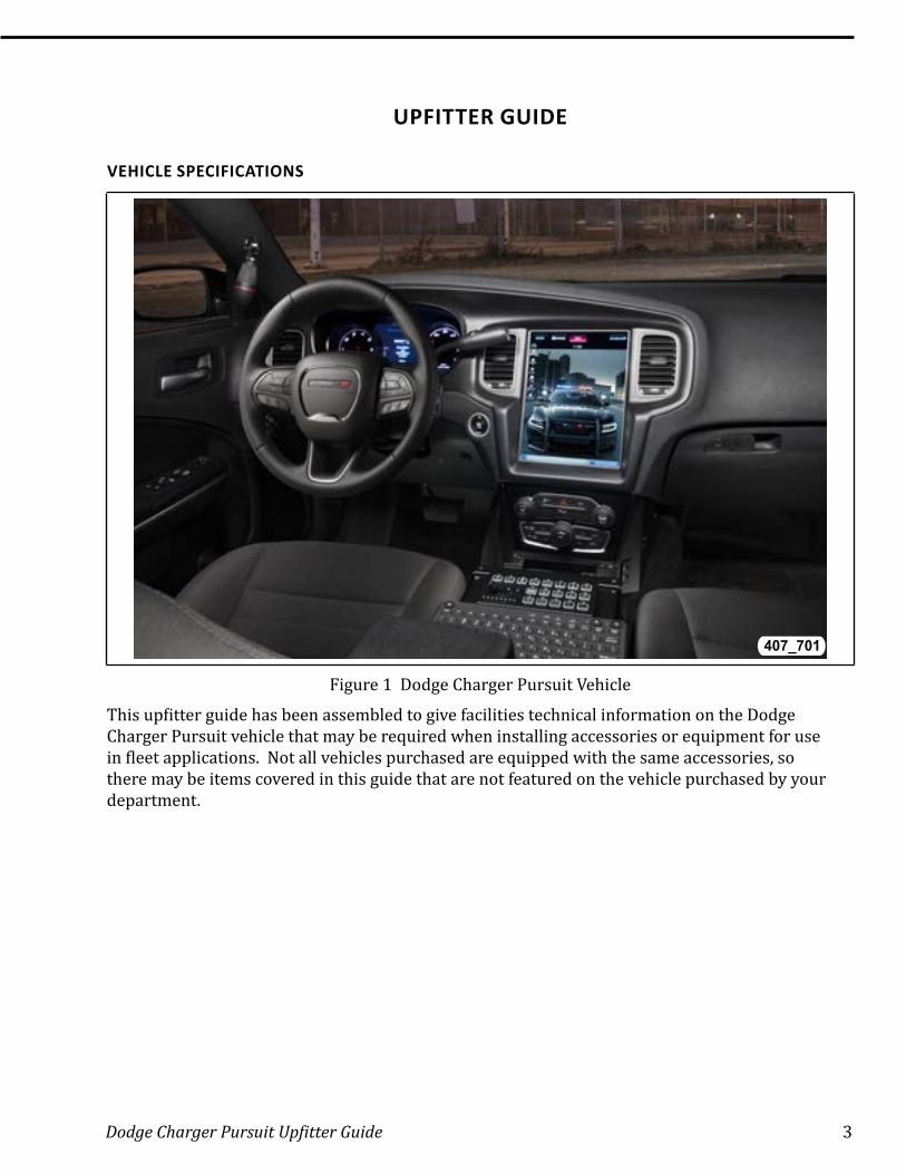
Figure 1 Dodge Charger Pursuit Vehicle
This upfitter guide has been assembled to give facilities technical information on the Dodge Charger Pursuit vehicle that may be required when installing accessories or equipment for use in fleet applications. Not all vehicles purchased are equipped with the same accessories, so there may be items covered in this guide that are not featured on the vehicle purchased by your department.
4 Dodge Charger Pursuit Upfitter Guide
VEHICLE DIMENSIONS
407_702
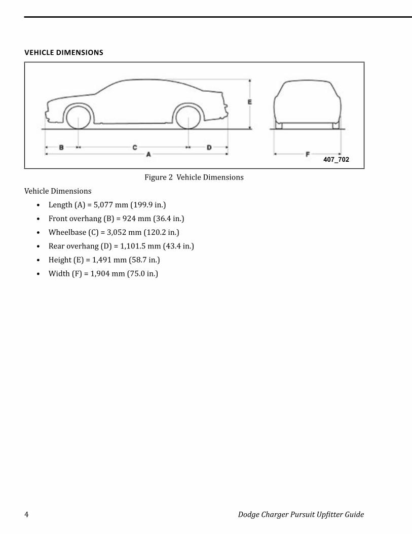
Figure 2 Vehicle Dimensions
Vehicle Dimensions
• Length (A) = 5,077 mm (199.9 in.)
• Front overhang (B) = 924 mm (36.4 in.)
• Wheelbase (C) = 3,052 mm (120.2 in.)
• Rear overhang (D) = 1,101.5 mm (43.4 in.)
• Height (E) = 1,491 mm (58.7 in.)
• Width (F) = 1,904 mm (75.0 in.)
Dodge Charger Pursuit Upfitter Guide 5
CHRYSLER FLEET WEBSITE
407_703
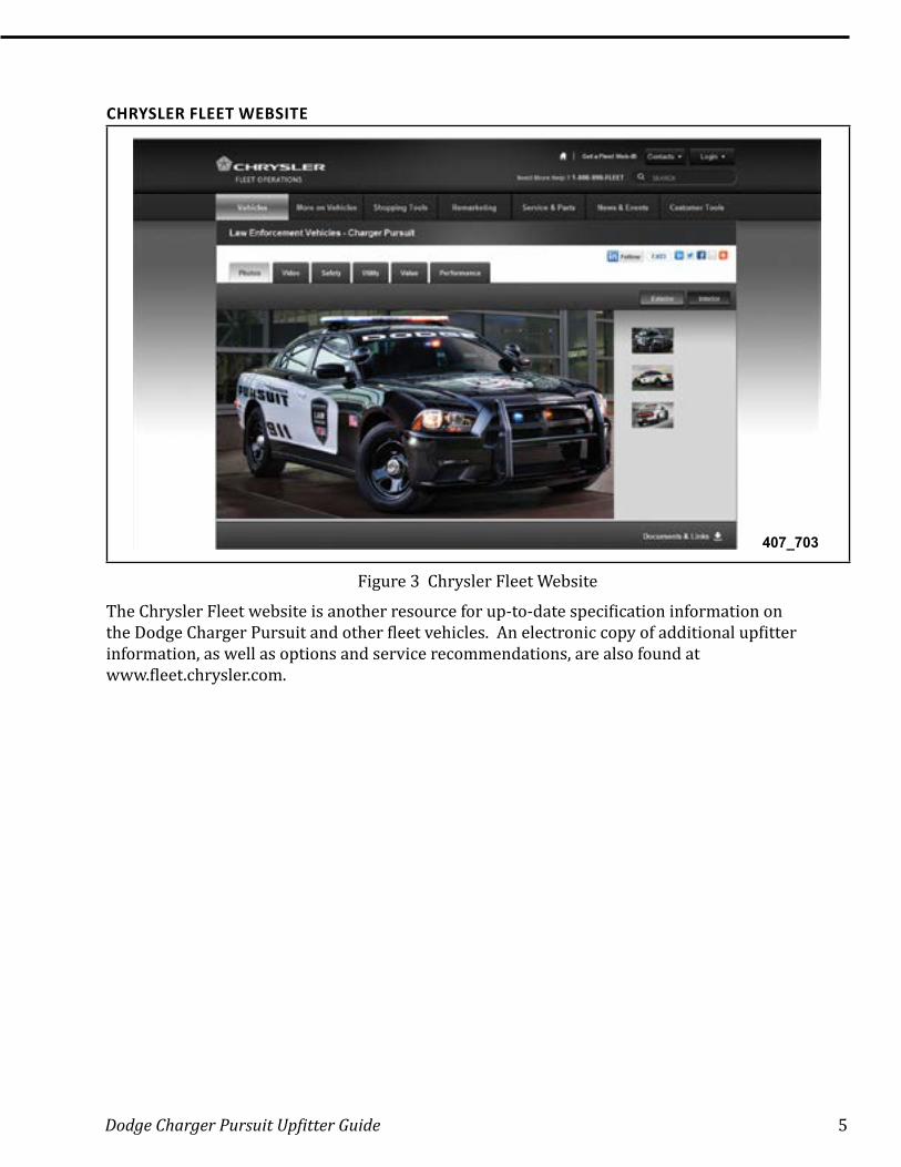
Figure 3 Chrysler Fleet Website
The Chrysler Fleet website is another resource for up-to-date specification information on the Dodge Charger Pursuit and other fleet vehicles. An electronic copy of additional upfitter information, as well as options and service recommendations, are also found at www.fleet.chrysler.com.
6 Dodge Charger Pursuit Upfitter Guide
Vehicle Systems Interface Module (VSIM) 2011–2014.5
16
712
407_750
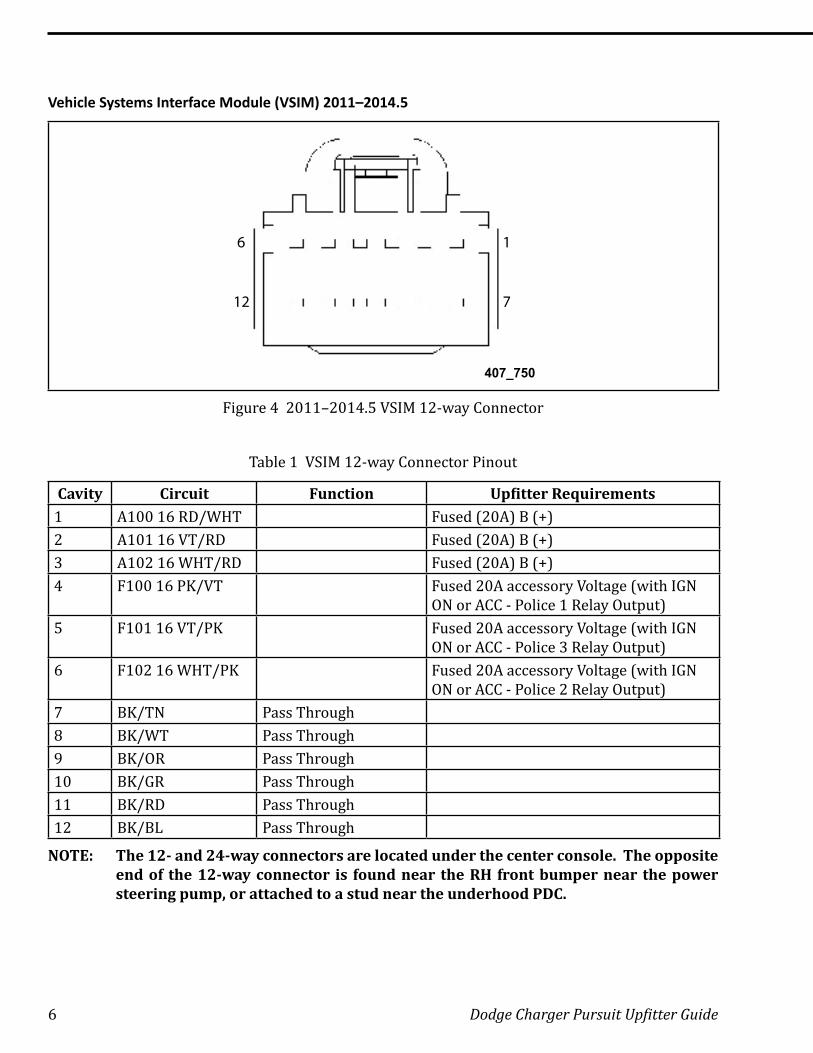
Figure 4 2011–2014.5 VSIM 12-way Connector
Table 1 VSIM 12-way Connector Pinout
Cavity Circuit Function Upfitter Requirements1 A100 16 RD/WHT Fused (20A) B (+)2 A101 16 VT/RD Fused (20A) B (+)3 A102 16 WHT/RD Fused (20A) B (+)4 F100 16 PK/VT Fused 20A accessory Voltage (with IGN
ON or ACC - Police 1 Relay Output)5 F101 16 VT/PK Fused 20A accessory Voltage (with IGN
ON or ACC - Police 3 Relay Output)6 F102 16 WHT/PK Fused 20A accessory Voltage (with IGN
ON or ACC - Police 2 Relay Output)7 BK/TN Pass Through8 BK/WT Pass Through9 BK/OR Pass Through10 BK/GR Pass Through11 BK/RD Pass Through12 BK/BL Pass Through
NOTE: The 12- and 24-way connectors are located under the center console. The opposite end of the 12-way connector is found near the RH front bumper near the power steering pump, or attached to a stud near the underhood PDC.
Dodge Charger Pursuit Upfitter Guide 7
19
11
5
14
10
18
24
407_751
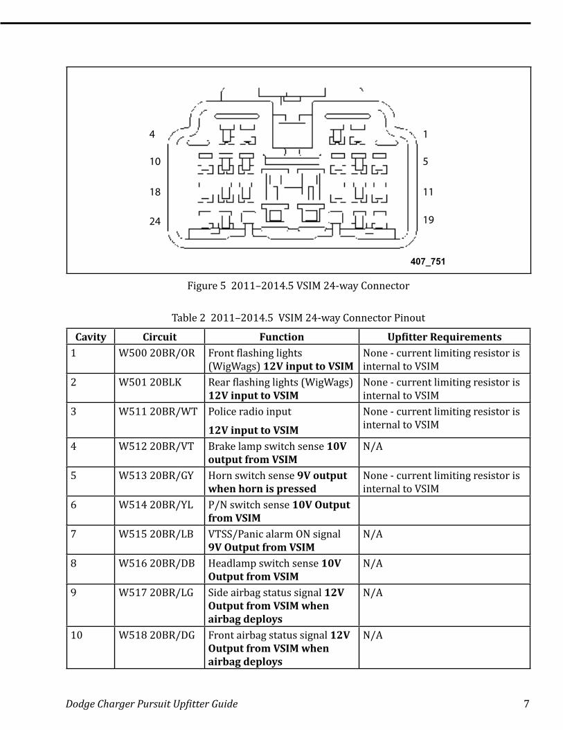
Figure 5 2011–2014.5 VSIM 24-way Connector
Table 2 2011–2014.5 VSIM 24-way Connector Pinout
Cavity Circuit Function Upfitter Requirements1 W500 20BR/OR Front flashing lights
(WigWags) 12V input to VSIMNone - current limiting resistor is internal to VSIM
2 W501 20BLK Rear flashing lights (WigWags) 12V input to VSIM
None - current limiting resistor is internal to VSIM
3 W511 20BR/WT Police radio input
12V input to VSIM
None - current limiting resistor is internal to VSIM
4 W512 20BR/VT Brake lamp switch sense 10V output from VSIM
N/A
5 W513 20BR/GY Horn switch sense 9V output when horn is pressed
None - current limiting resistor is internal to VSIM
6 W514 20BR/YL P/N switch sense 10V Output from VSIM
7 W515 20BR/LB VTSS/Panic alarm ON signal 9V Output from VSIM
N/A
8 W516 20BR/DB Headlamp switch sense 10V Output from VSIM
N/A
9 W517 20BR/LG Side airbag status signal 12V Output from VSIM when airbag deploys
N/A
10 W518 20BR/DG Front airbag status signal 12V Output from VSIM when airbag deploys
N/A
8 Dodge Charger Pursuit Upfitter Guide
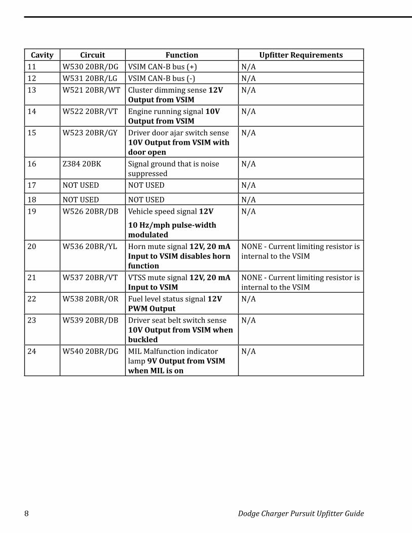
Cavity Circuit Function Upfitter Requirements11 W530 20BR/DG VSIM CAN-B bus (+) N/A12 W531 20BR/LG VSIM CAN-B bus (-) N/A13 W521 20BR/WT Cluster dimming sense 12V
Output from VSIMN/A
14 W522 20BR/VT Engine running signal 10V Output from VSIM
N/A
15 W523 20BR/GY Driver door ajar switch sense 10V Output from VSIM with door open
N/A
16 Z384 20BK Signal ground that is noise suppressed
N/A
17 NOT USED NOT USED N/A
18 NOT USED NOT USED N/A19 W526 20BR/DB Vehicle speed signal 12V
10 Hz/mph pulse-width modulated
N/A
20 W536 20BR/YL Horn mute signal 12V, 20 mA Input to VSIM disables horn function
NONE - Current limiting resistor is internal to the VSIM
21 W537 20BR/VT VTSS mute signal 12V, 20 mA Input to VSIM
NONE - Current limiting resistor is internal to the VSIM
22 W538 20BR/OR Fuel level status signal 12V PWM Output
N/A
23 W539 20BR/DB Driver seat belt switch sense 10V Output from VSIM when buckled
N/A
24 W540 20BR/DG MIL Malfunction indicator lamp 9V Output from VSIM when MIL is on
N/A
Dodge Charger Pursuit Upfitter Guide 9
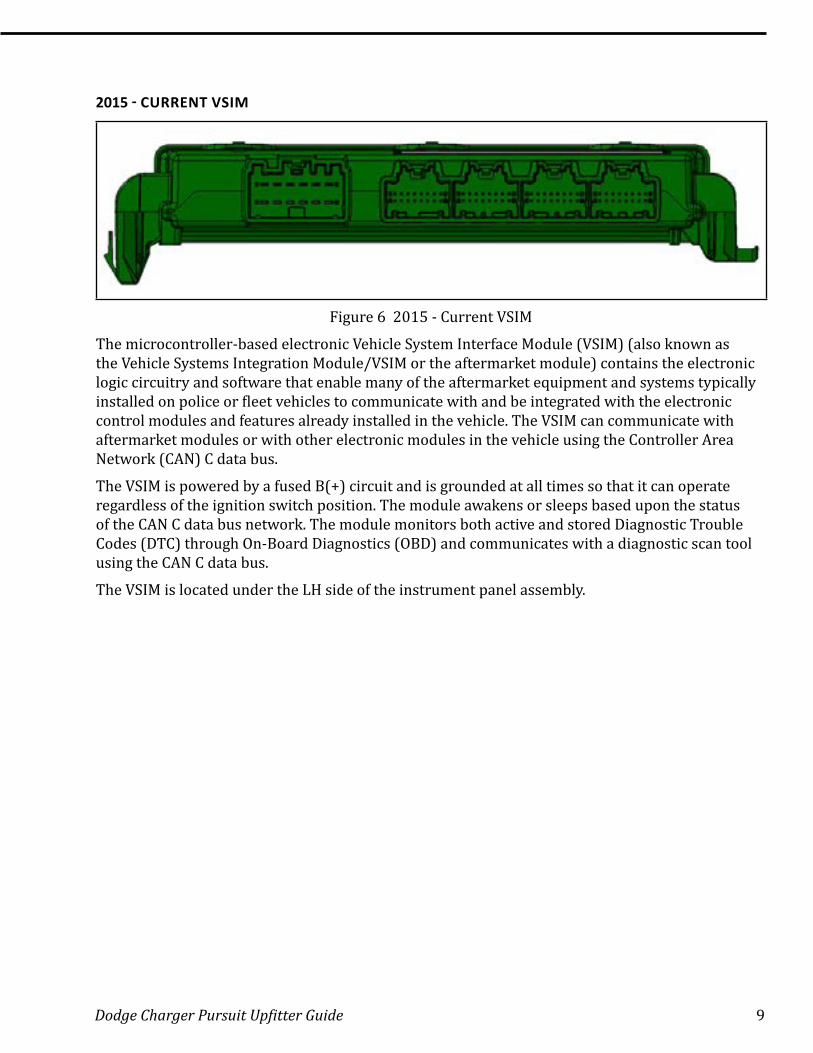
2015 - CURRENT VSIM
Figure 6 2015 - Current VSIM
The microcontroller-based electronic Vehicle System Interface Module (VSIM) (also known as the Vehicle Systems Integration Module/VSIM or the aftermarket module) contains the electronic logic circuitry and software that enable many of the aftermarket equipment and systems typically installed on police or fleet vehicles to communicate with and be integrated with the electronic control modules and features already installed in the vehicle. The VSIM can communicate with aftermarket modules or with other electronic modules in the vehicle using the Controller Area Network (CAN) C data bus.
The VSIM is powered by a fused B(+) circuit and is grounded at all times so that it can operate regardless of the ignition switch position. The module awakens or sleeps based upon the status of the CAN C data bus network. The module monitors both active and stored Diagnostic Trouble Codes (DTC) through On-Board Diagnostics (OBD) and communicates with a diagnostic scan tool using the CAN C data bus.
The VSIM is located under the LH side of the instrument panel assembly.
10 Dodge Charger Pursuit Upfitter Guide
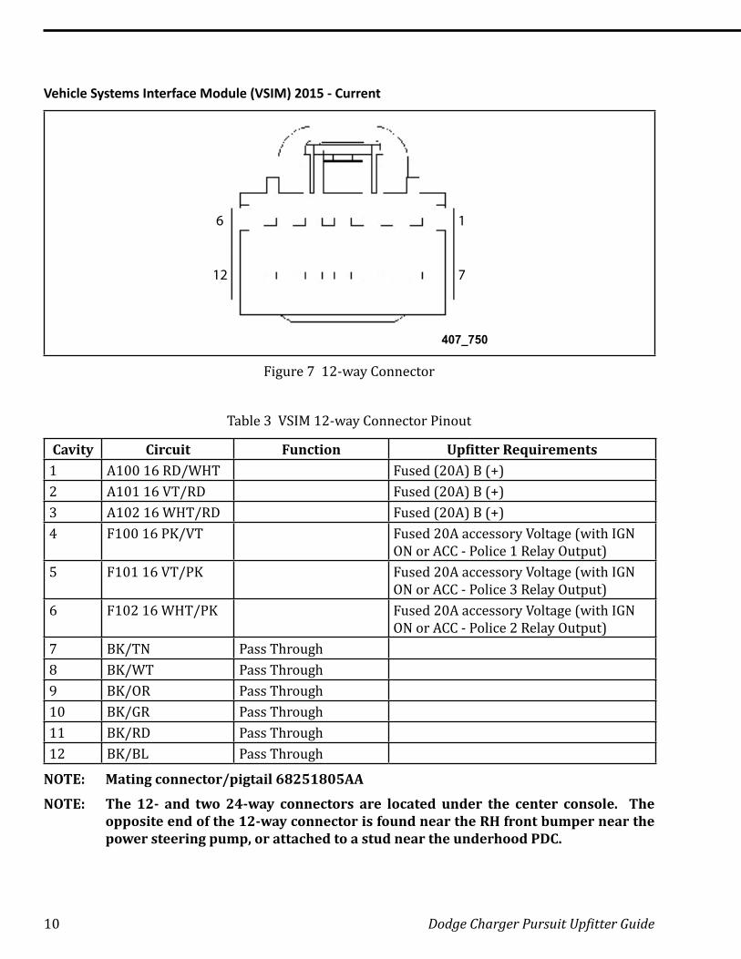
Vehicle Systems Interface Module (VSIM) 2015 - Current
16
712
407_750
Figure 7 12-way Connector
Table 3 VSIM 12-way Connector Pinout
Cavity Circuit Function Upfitter Requirements1 A100 16 RD/WHT Fused (20A) B (+)2 A101 16 VT/RD Fused (20A) B (+)3 A102 16 WHT/RD Fused (20A) B (+)4 F100 16 PK/VT Fused 20A accessory Voltage (with IGN
ON or ACC - Police 1 Relay Output)5 F101 16 VT/PK Fused 20A accessory Voltage (with IGN
ON or ACC - Police 3 Relay Output)6 F102 16 WHT/PK Fused 20A accessory Voltage (with IGN
ON or ACC - Police 2 Relay Output)7 BK/TN Pass Through8 BK/WT Pass Through9 BK/OR Pass Through10 BK/GR Pass Through11 BK/RD Pass Through12 BK/BL Pass Through
NOTE: Mating connector/pigtail 68251805AA
NOTE: The 12- and two 24-way connectors are located under the center console. The opposite end of the 12-way connector is found near the RH front bumper near the power steering pump, or attached to a stud near the underhood PDC.
Dodge Charger Pursuit Upfitter Guide 11
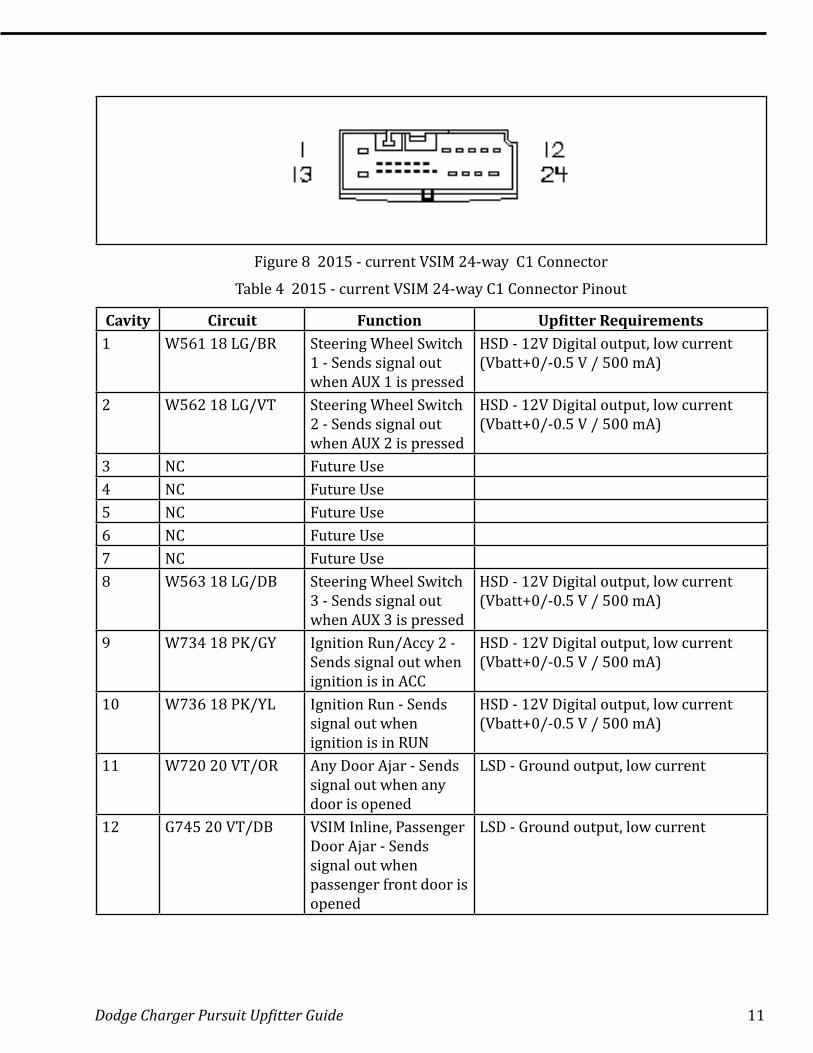
Figure 8 2015 - current VSIM 24-way C1 Connector
Table 4 2015 - current VSIM 24-way C1 Connector Pinout
Cavity Circuit Function Upfitter Requirements1 W561 18 LG/BR Steering Wheel Switch
1 - Sends signal out when AUX 1 is pressed
HSD - 12V Digital output, low current (Vbatt+0/-0.5 V / 500 mA)
2 W562 18 LG/VT Steering Wheel Switch 2 - Sends signal out when AUX 2 is pressed
HSD - 12V Digital output, low current (Vbatt+0/-0.5 V / 500 mA)
3 NC Future Use4 NC Future Use5 NC Future Use6 NC Future Use7 NC Future Use8 W563 18 LG/DB Steering Wheel Switch
3 - Sends signal out when AUX 3 is pressed
HSD - 12V Digital output, low current (Vbatt+0/-0.5 V / 500 mA)
9 W734 18 PK/GY Ignition Run/Accy 2 - Sends signal out when ignition is in ACC
HSD - 12V Digital output, low current (Vbatt+0/-0.5 V / 500 mA)
10 W736 18 PK/YL Ignition Run - Sends signal out when ignition is in RUN
HSD - 12V Digital output, low current (Vbatt+0/-0.5 V / 500 mA)
11 W720 20 VT/OR Any Door Ajar - Sends signal out when any door is opened
LSD - Ground output, low current
12 G745 20 VT/DB VSIM Inline, Passenger Door Ajar - Sends signal out when passenger front door is opened
LSD - Ground output, low current
12 Dodge Charger Pursuit Upfitter Guide
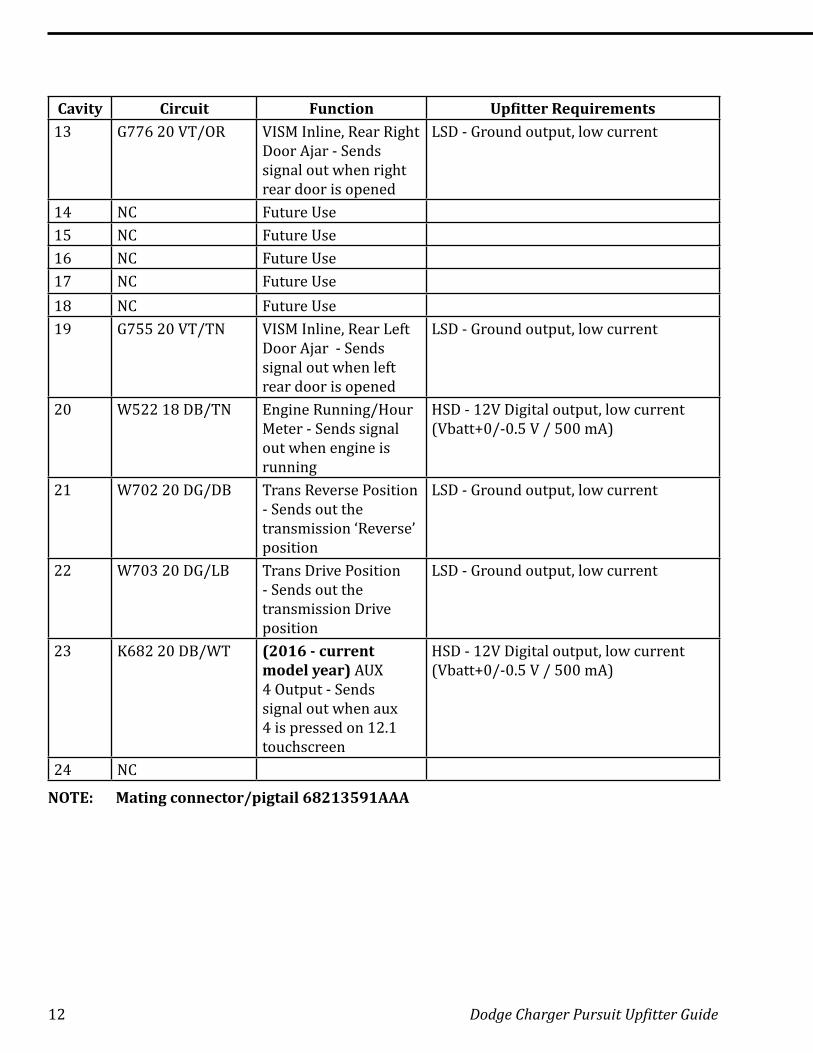
Cavity Circuit Function Upfitter Requirements13 G776 20 VT/OR VISM Inline, Rear Right
Door Ajar - Sends signal out when right rear door is opened
LSD - Ground output, low current
14 NC Future Use15 NC Future Use16 NC Future Use17 NC Future Use18 NC Future Use19 G755 20 VT/TN VISM Inline, Rear Left
Door Ajar - Sends signal out when left rear door is opened
LSD - Ground output, low current
20 W522 18 DB/TN Engine Running/Hour Meter - Sends signal out when engine is running
HSD - 12V Digital output, low current (Vbatt+0/-0.5 V / 500 mA)
21 W702 20 DG/DB Trans Reverse Position - Sends out the transmission ‘Reverse’ position
LSD - Ground output, low current
22 W703 20 DG/LB Trans Drive Position - Sends out the transmission Drive position
LSD - Ground output, low current
23 K682 20 DB/WT (2016 - current model year) AUX 4 Output - Sends signal out when aux 4 is pressed on 12.1 touchscreen
HSD - 12V Digital output, low current (Vbatt+0/-0.5 V / 500 mA)
24 NC
NOTE: Mating connector/pigtail 68213591AAA
Dodge Charger Pursuit Upfitter Guide 13
19
11
5
14
10
18
24
407_751
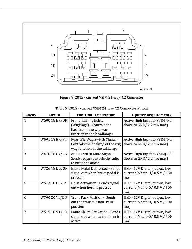
Figure 9 2015 - current VSIM 24-way C2 Connector
Table 5 2015 - current VSIM 24-way C2 Connector Pinout
Cavity Circuit Function - Description Upfitter Requirements1 W500 18 BR/OR Front flashing lights
(WigWags) - Controls the flashing of the wig wag function in the headlamps
Active High Input to VSIM (Pull down to GND/ 2.2 mA max)
2 W501 18 BR/VT Rear Wig Wag Switch Signal - Controls the flashing of the wig wag function in the taillamps
Active High Input to VSIM (Pull down to GND/ 2.2 mA max)
3 W640 18 GY/DG Audio Switch Mute Signal - Sends request to vehicle radio to mute the audio
Active High Input to VSIM(Pull down to GND/ 2.2 mA max)
4 W726 18 DG/OR Brake Pedal Depressed - Sends signal out when brake pedal is pressed
HSD - 12V Digital output, low current (Vbatt+0/-0.5 V / 250 mA)
5 W513 18 BR/GY Horn Activation - Sends signal out when horn is pressed
HSD - 12V Digital output, low current (Vbatt+0/-0.5 V / 500 mA)
6 W700 20 YL/DB Trans Park Position - Sends out the transmission ‘Park’ position
HSD - 12V Digital output, low current (Vbatt+0/-0.5 V / 500 mA)
7 W515 18 VT/LB Panic Alarm Activation - Sends signal out when panic alarm is active
HSD - 12V Digital output, low current (Vbatt+0/-0.5 V / 500 mA)
14 Dodge Charger Pursuit Upfitter Guide
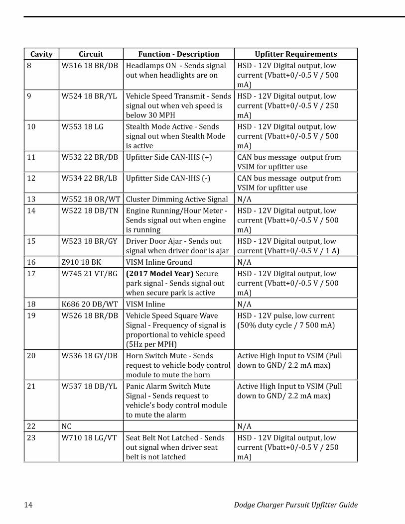
Cavity Circuit Function - Description Upfitter Requirements8 W516 18 BR/DB Headlamps ON - Sends signal
out when headlights are onHSD - 12V Digital output, low current (Vbatt+0/-0.5 V / 500 mA)
9 W524 18 BR/YL Vehicle Speed Transmit - Sends signal out when veh speed is below 30 MPH
HSD - 12V Digital output, low current (Vbatt+0/-0.5 V / 250 mA)
10 W553 18 LG Stealth Mode Active - Sends signal out when Stealth Mode is active
HSD - 12V Digital output, low current (Vbatt+0/-0.5 V / 500 mA)
11 W532 22 BR/DB Upfitter Side CAN-IHS (+) CAN bus message output from VSIM for upfitter use
12 W534 22 BR/LB Upfitter Side CAN-IHS (-) CAN bus message output from VSIM for upfitter use
13 W552 18 OR/WT Cluster Dimming Active Signal N/A14 W522 18 DB/TN Engine Running/Hour Meter -
Sends signal out when engine is running
HSD - 12V Digital output, low current (Vbatt+0/-0.5 V / 500 mA)
15 W523 18 BR/GY Driver Door Ajar - Sends out signal when driver door is ajar
HSD - 12V Digital output, low current (Vbatt+0/-0.5 V / 1 A)
16 Z910 18 BK VISM Inline Ground N/A17 W745 21 VT/BG (2017 Model Year) Secure
park signal - Sends signal out when secure park is active
HSD - 12V Digital output, low current (Vbatt+0/-0.5 V / 500 mA)
18 K686 20 DB/WT VISM Inline N/A19 W526 18 BR/DB Vehicle Speed Square Wave
Signal - Frequency of signal is proportional to vehicle speed (5Hz per MPH)
HSD - 12V pulse, low current (50% duty cycle / 7 500 mA)
20 W536 18 GY/DB Horn Switch Mute - Sends request to vehicle body control module to mute the horn
Active High Input to VSIM (Pull down to GND/ 2.2 mA max)
21 W537 18 DB/YL Panic Alarm Switch Mute Signal - Sends request to vehicle’s body control module to mute the alarm
Active High Input to VSIM (Pull down to GND/ 2.2 mA max)
22 NC N/A23 W710 18 LG/VT Seat Belt Not Latched - Sends
out signal when driver seat belt is not latched
HSD - 12V Digital output, low current (Vbatt+0/-0.5 V / 250 mA)
Dodge Charger Pursuit Upfitter Guide 15
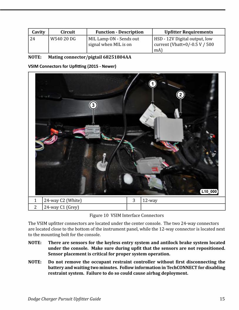
Cavity Circuit Function - Description Upfitter Requirements24 W540 20 DG MIL Lamp ON - Sends out
signal when MIL is onHSD - 12V Digital output, low current (Vbatt+0/-0.5 V / 500 mA)
NOTE: Mating connector/pigtail 68251804AA
VSIM Connectors for Upfitting (2015 - Newer)
1
2
3
L10_000
1 24-way C2 (White) 3 12-way2 24-way C1 (Grey)
Figure 10 VSIM Interface Connectors
The VSIM upfitter connectors are located under the center console. The two 24-way connectors are located close to the bottom of the instrument panel, while the 12-way connector is located next to the mounting bolt for the console.
NOTE: There are sensors for the keyless entry system and antilock brake system located under the console. Make sure during upfit that the sensors are not repositioned. Sensor placement is critical for proper system operation.
NOTE: Do not remove the occupant restraint controller without first disconnecting the battery and waiting two minutes. Follow information in TechCONNECT for disabling restraint system. Failure to do so could cause airbag deployment.
16 Dodge Charger Pursuit Upfitter Guide
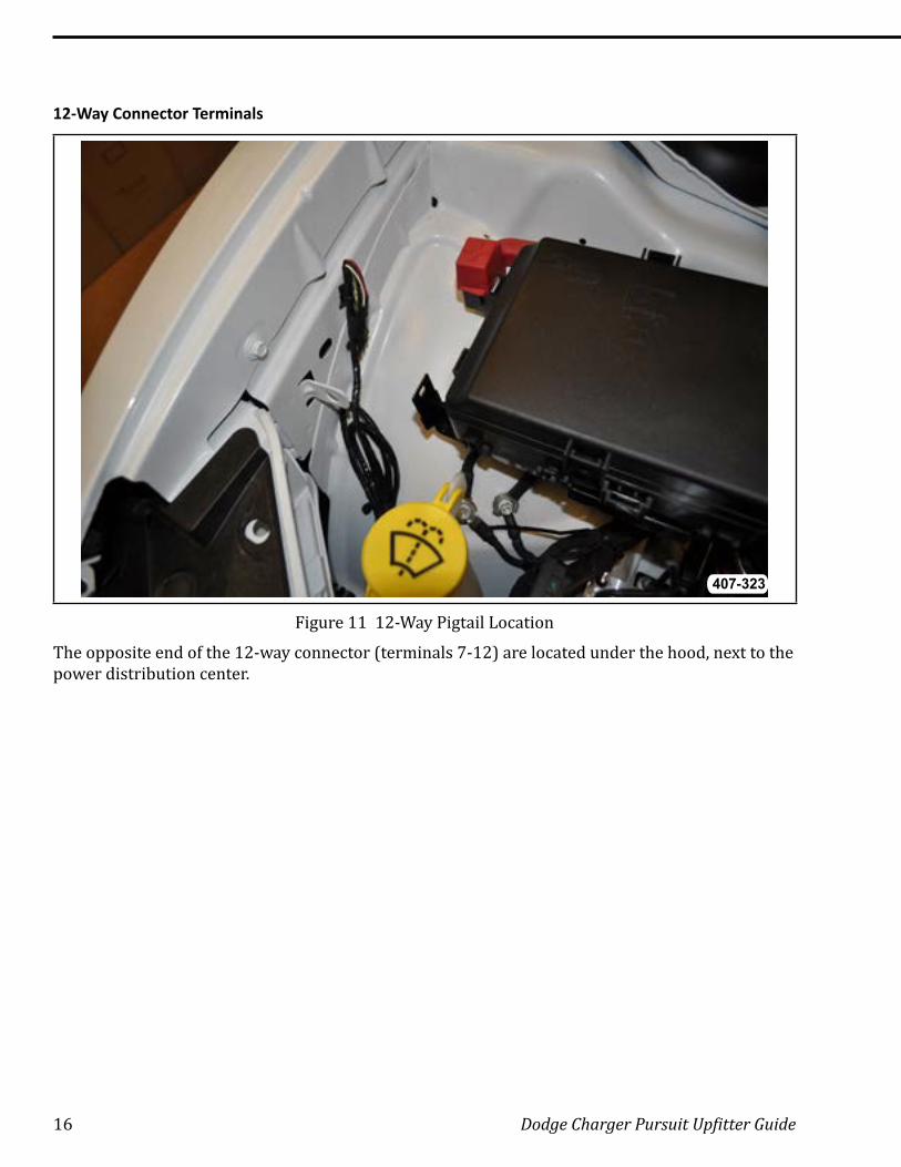
12-Way Connector Terminals
407-323
Figure 11 12-Way Pigtail Location
The opposite end of the 12-way connector (terminals 7-12) are located under the hood, next to the power distribution center.
Dodge Charger Pursuit Upfitter Guide 17
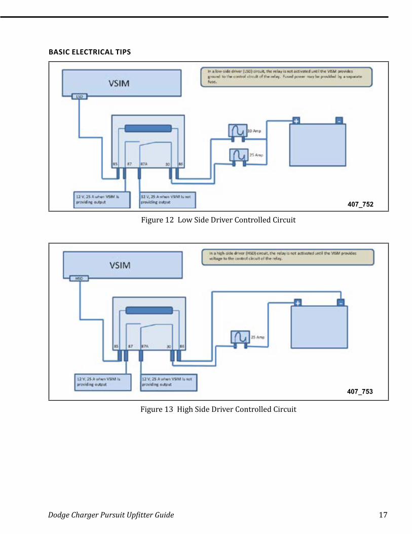
BASIC ELECTRICAL TIPS
407_752
Figure 12 Low Side Driver Controlled Circuit
407_753
Figure 13 High Side Driver Controlled Circuit
18 Dodge Charger Pursuit Upfitter Guide
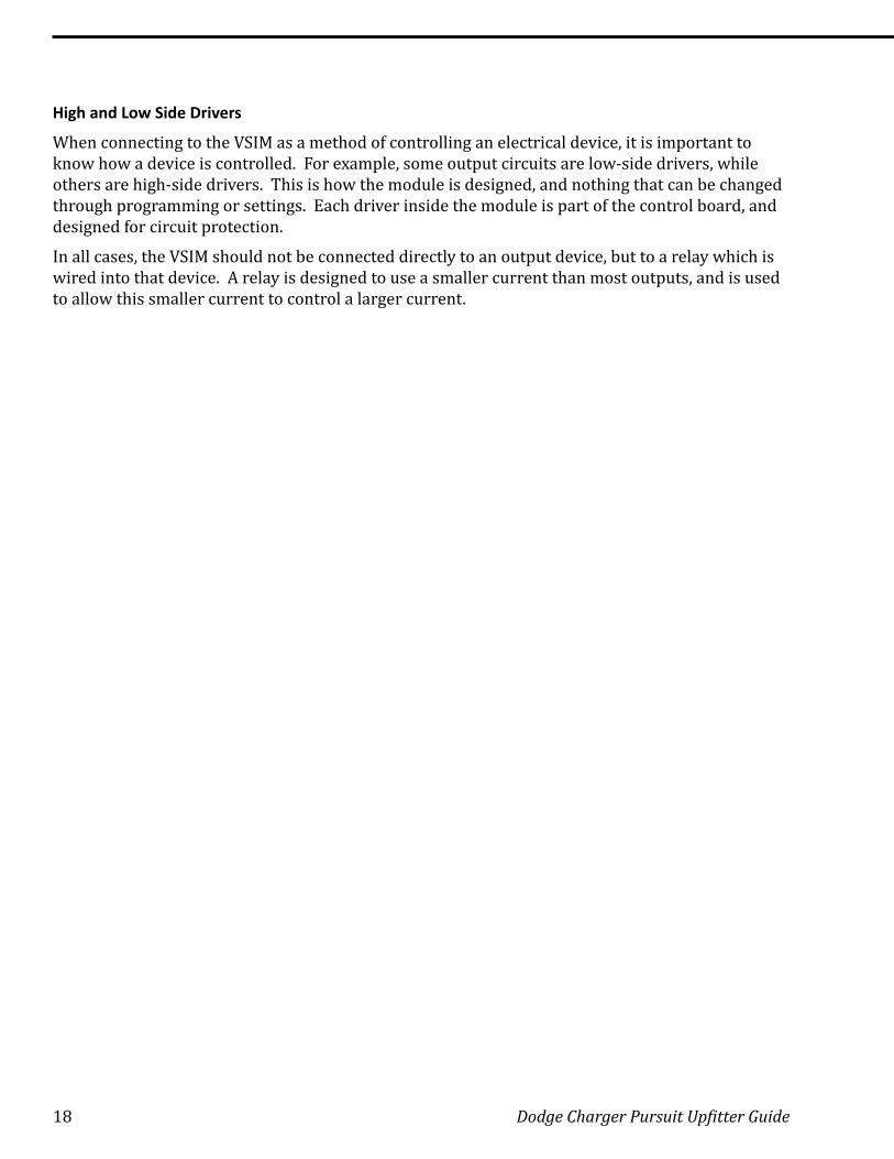
High and Low Side Drivers
When connecting to the VSIM as a method of controlling an electrical device, it is important to know how a device is controlled. For example, some output circuits are low-side drivers, while others are high-side drivers. This is how the module is designed, and nothing that can be changed through programming or settings. Each driver inside the module is part of the control board, and designed for circuit protection.
In all cases, the VSIM should not be connected directly to an output device, but to a relay which is wired into that device. A relay is designed to use a smaller current than most outputs, and is used to allow this smaller current to control a larger current.
Dodge Charger Pursuit Upfitter Guide 19
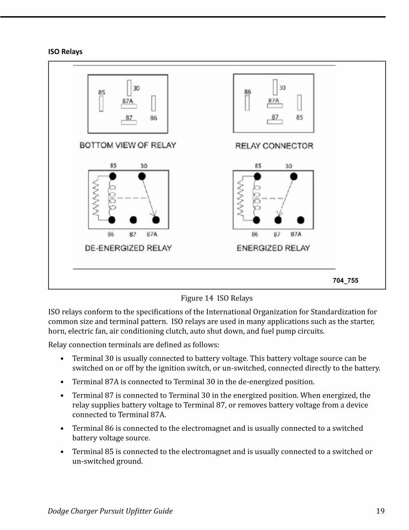
ISO Relays
704_755
Figure 14 ISO Relays
ISO relays conform to the specifications of the International Organization for Standardization for common size and terminal pattern. ISO relays are used in many applications such as the starter, horn, electric fan, air conditioning clutch, auto shut down, and fuel pump circuits.
Relay connection terminals are defined as follows:
• Terminal 30 is usually connected to battery voltage. This battery voltage source can be switched on or off by the ignition switch, or un-switched, connected directly to the battery.
• Terminal 87A is connected to Terminal 30 in the de-energized position.
• Terminal 87 is connected to Terminal 30 in the energized position. When energized, the relay supplies battery voltage to Terminal 87, or removes battery voltage from a device connected to Terminal 87A .
• Terminal 86 is connected to the electromagnet and is usually connected to a switched battery voltage source.
• Terminal 85 is connected to the electromagnet and is usually connected to a switched or un-switched ground.
20 Dodge Charger Pursuit Upfitter Guide
Micro Relays
407_754
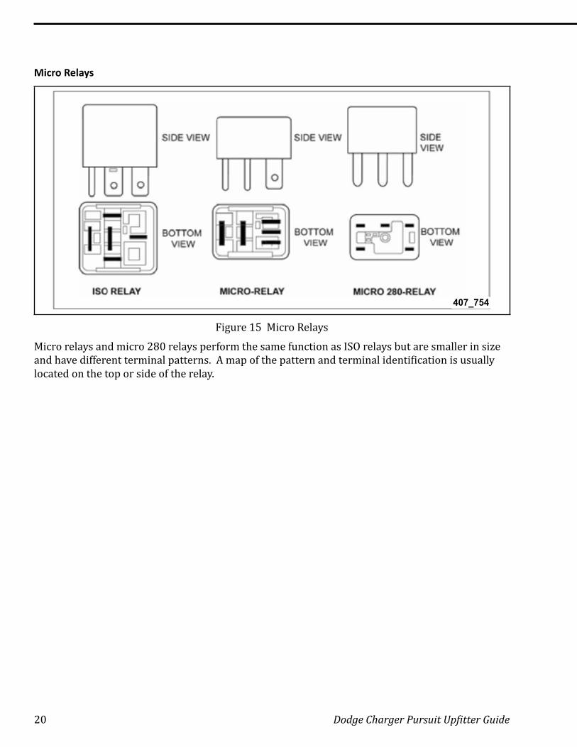
Figure 15 Micro Relays
Micro relays and micro 280 relays perform the same function as ISO relays but are smaller in size and have different terminal patterns. A map of the pattern and terminal identification is usually located on the top or side of the relay.
Dodge Charger Pursuit Upfitter Guide 21
UCONNECT 12.1
407_756
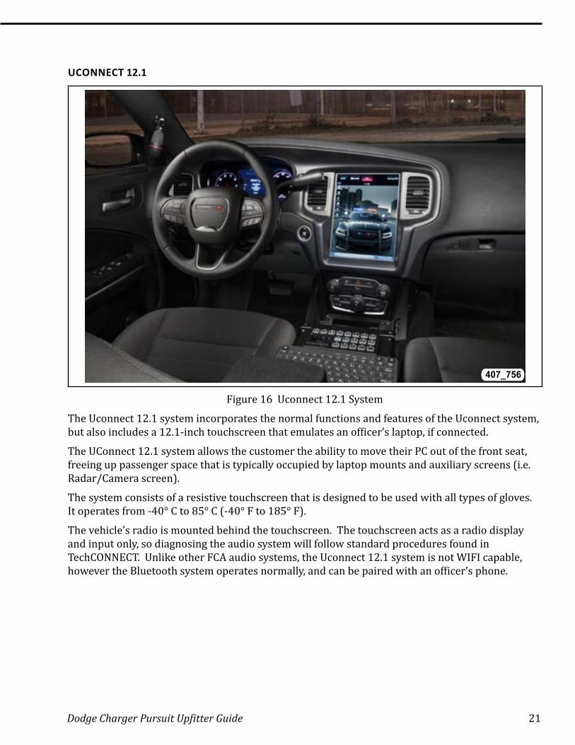
Figure 16 Uconnect 12.1 System
The Uconnect 12.1 system incorporates the normal functions and features of the Uconnect system, but also includes a 12.1-inch touchscreen that emulates an officer’s laptop, if connected.
The UConnect 12.1 system allows the customer the ability to move their PC out of the front seat, freeing up passenger space that is typically occupied by laptop mounts and auxiliary screens (i.e. Radar/Camera screen) .
The system consists of a resistive touchscreen that is designed to be used with all types of gloves. It operates from -40° C to 85° C (-40° F to 185° F).
The vehicle’s radio is mounted behind the touchscreen. The touchscreen acts as a radio display and input only, so diagnosing the audio system will follow standard procedures found in TechCONNECT. Unlike other FCA audio systems, the Uconnect 12.1 system is not WIFI capable, however the Bluetooth system operates normally, and can be paired with an officer’s phone.
22 Dodge Charger Pursuit Upfitter Guide
Uconnect Operation
21 407_760
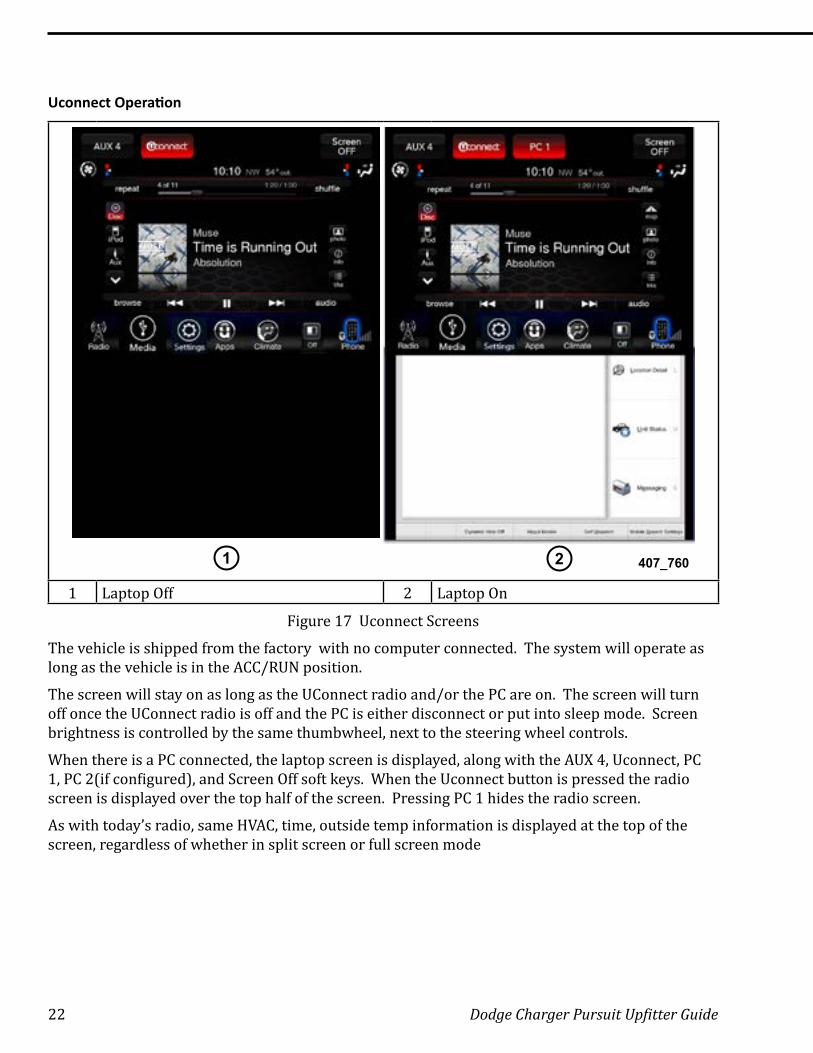
1 Laptop Off 2 Laptop On
Figure 17 Uconnect Screens
The vehicle is shipped from the factory with no computer connected. The system will operate as long as the vehicle is in the ACC/RUN position.
The screen will stay on as long as the UConnect radio and/or the PC are on. The screen will turn off once the UConnect radio is off and the PC is either disconnect or put into sleep mode. Screen brightness is controlled by the same thumbwheel, next to the steering wheel controls.
When there is a PC connected, the laptop screen is displayed, along with the AUX 4, Uconnect, PC 1, PC 2(if configured), and Screen Off soft keys. When the Uconnect button is pressed the radio screen is displayed over the top half of the screen. Pressing PC 1 hides the radio screen.
As with today’s radio, same HVAC, time, outside temp information is displayed at the top of the screen, regardless of whether in split screen or full screen mode
Dodge Charger Pursuit Upfitter Guide 23
Connections
1
23
5
4
407_757
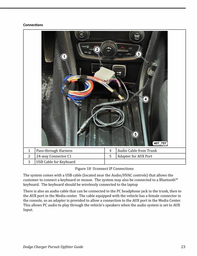
1 Pass-through Harness 4 Audio Cable from Trunk2 24-way Connector C1 5 Adapter for AUX Port3 USB Cable for Keyboard
Figure 18 Uconnect IP Connections
The system comes with a USB cable (located near the Audio/HVAC controls) that allows the customer to connect a keyboard or mouse. The system may also be connected to a Bluetooth™ keyboard. The keyboard should be wirelessly connected to the laptop
There is also an audio cable that can be connected to the PC headphone jack in the trunk, then to the AUX port in the Media center. The cable equipped with the vehicle has a female connector in the console, so an adapter is provided to allow a connection to the AUX port in the Media Center. This allows PC audio to play through the vehicle’s speakers when the audio system is set to AUX Input.
24 Dodge Charger Pursuit Upfitter Guide
Connections in Trunk
407_758
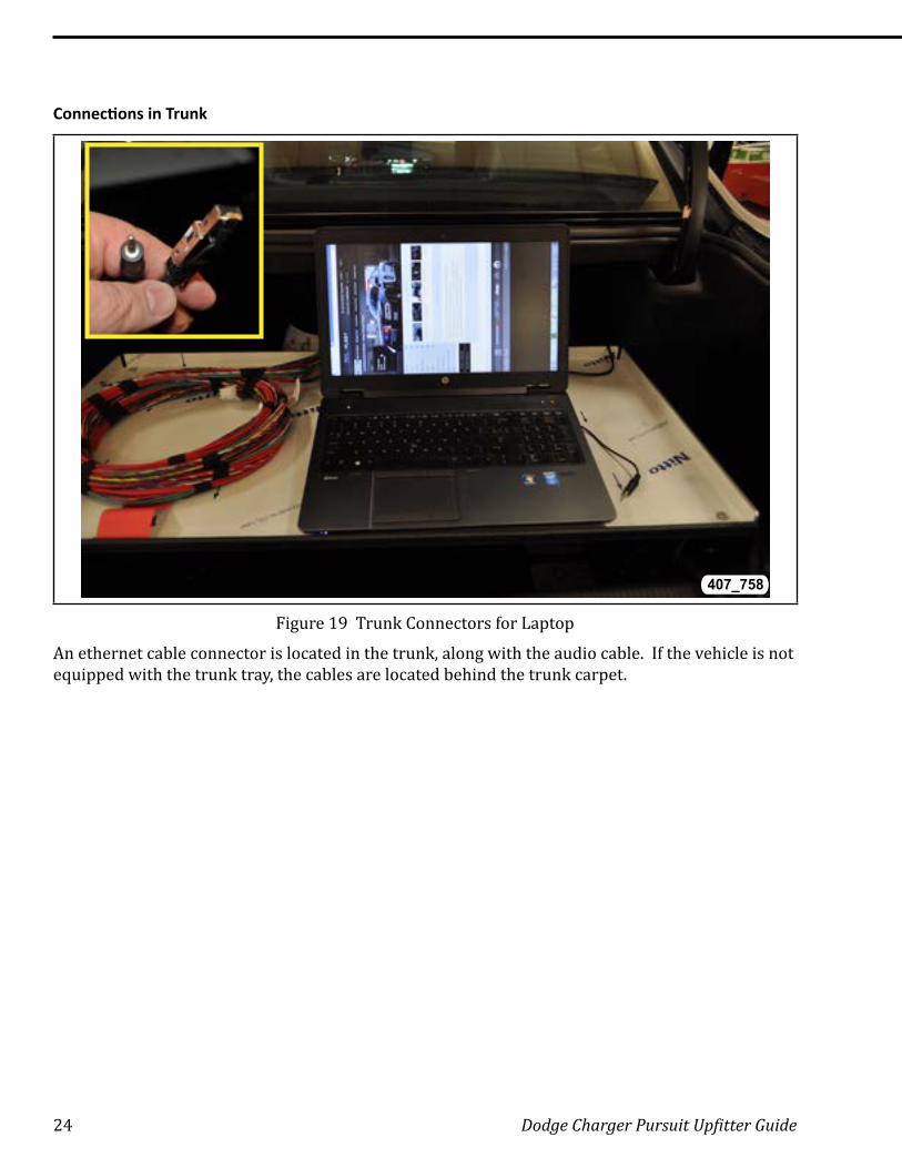
Figure 19 Trunk Connectors for Laptop
An ethernet cable connector is located in the trunk, along with the audio cable. If the vehicle is not equipped with the trunk tray, the cables are located behind the trunk carpet.
Dodge Charger Pursuit Upfitter Guide 25
Laptop Configuration
2
1
3
5
4
407_761
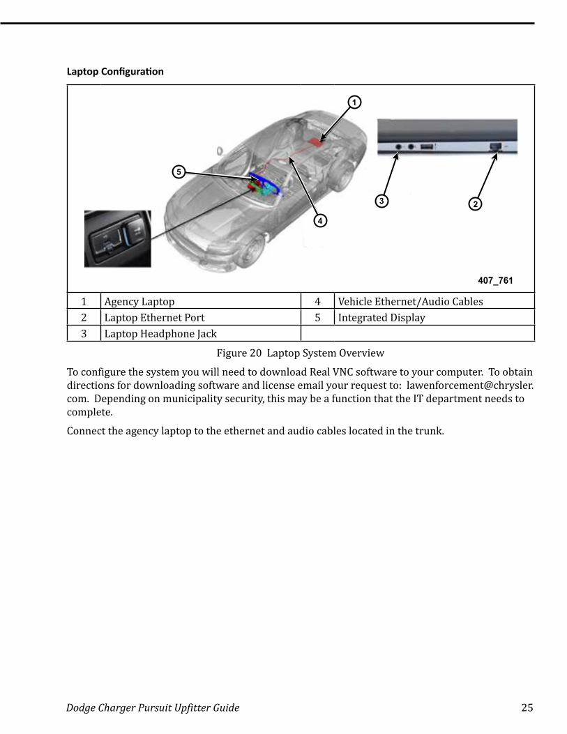
1 Agency Laptop 4 Vehicle Ethernet/Audio Cables2 Laptop Ethernet Port 5 Integrated Display3 Laptop Headphone Jack
Figure 20 Laptop System Overview
To configure the system you will need to download Real VNC software to your computer. To obtain directions for downloading software and license email your request to: [email protected]. Depending on municipality security, this may be a function that the IT department needs to complete.
Connect the agency laptop to the ethernet and audio cables located in the trunk.
26 Dodge Charger Pursuit Upfitter Guide
Laptop Display
407_762
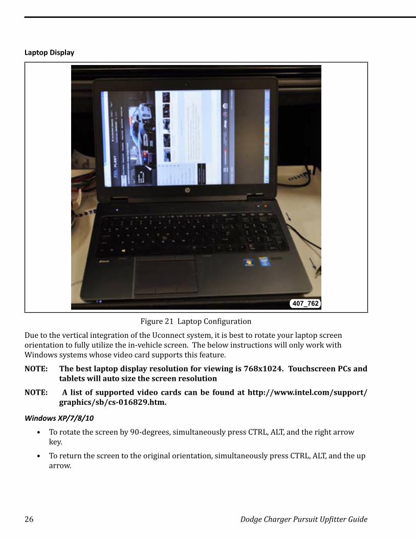
Figure 21 Laptop Configuration
Due to the vertical integration of the Uconnect system, it is best to rotate your laptop screen orientation to fully utilize the in-vehicle screen. The below instructions will only work with Windows systems whose video card supports this feature.
NOTE: The best laptop display resolution for viewing is 768x1024. Touchscreen PCs and tablets will auto size the screen resolution
NOTE: A list of supported video cards can be found at http://www.intel.com/support/graphics/sb/cs-016829.htm.
Windows XP/7/8/10
• To rotate the screen by 90-degrees, simultaneously press CTRL, ALT, and the right arrow key .
• To return the screen to the original orientation, simultaneously press CTRL, ALT, and the up arrow.
Dodge Charger Pursuit Upfitter Guide 27
System Connections Inside Vehicle
1 2
407_763
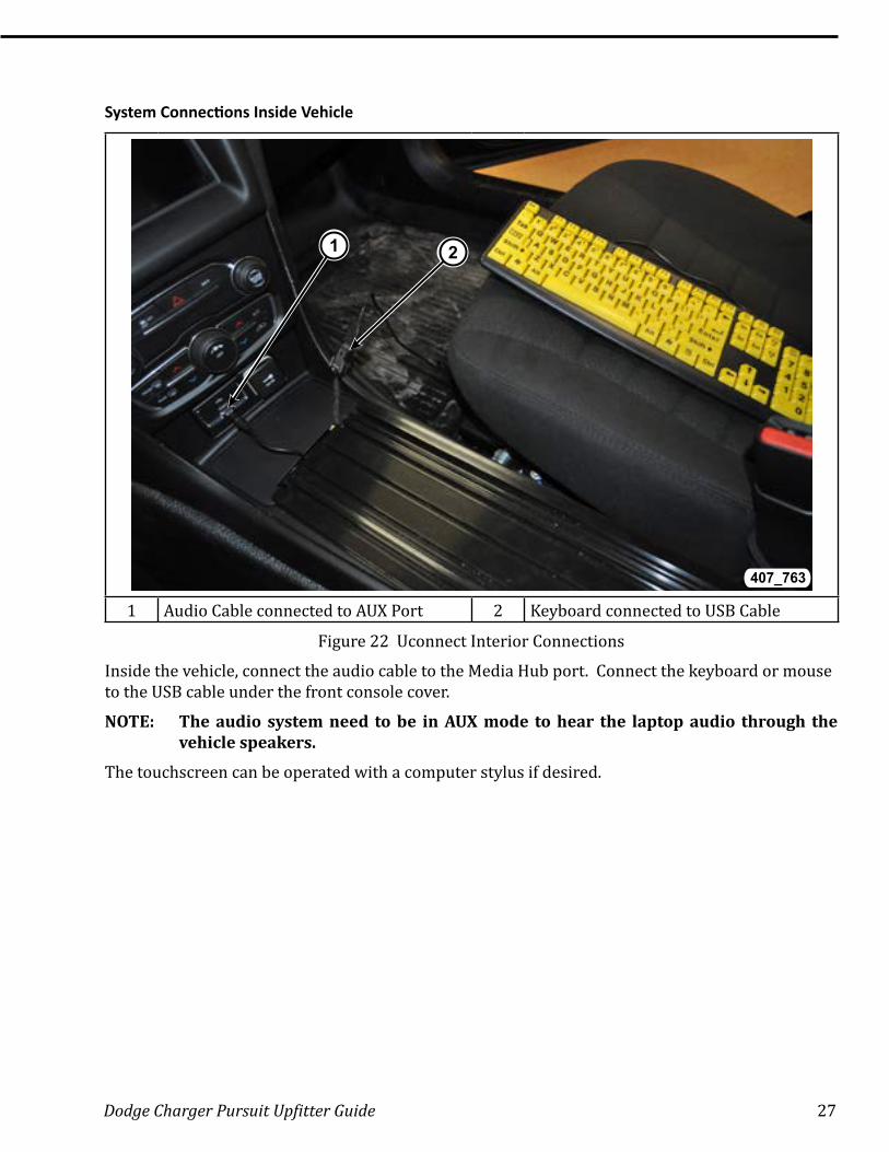
1 Audio Cable connected to AUX Port 2 Keyboard connected to USB Cable
Figure 22 Uconnect Interior Connections
Inside the vehicle, connect the audio cable to the Media Hub port. Connect the keyboard or mouse to the USB cable under the front console cover.
NOTE: The audio system need to be in AUX mode to hear the laptop audio through the vehicle speakers.
The touchscreen can be operated with a computer stylus if desired.
28 Dodge Charger Pursuit Upfitter Guide
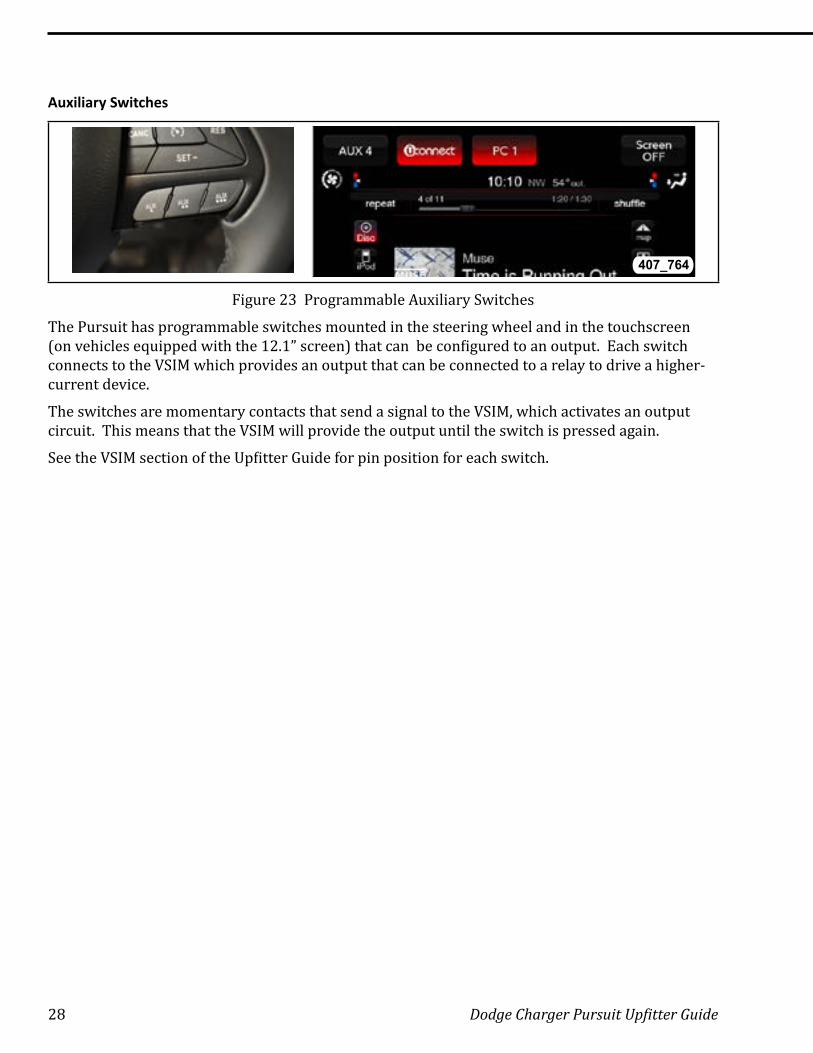
Auxiliary Switches
407_764
Figure 23 Programmable Auxiliary Switches
The Pursuit has programmable switches mounted in the steering wheel and in the touchscreen (on vehicles equipped with the 12.1” screen) that can be configured to an output. Each switch connects to the VSIM which provides an output that can be connected to a relay to drive a higher-current device.
The switches are momentary contacts that send a signal to the VSIM, which activates an output circuit. This means that the VSIM will provide the output until the switch is pressed again.
See the VSIM section of the Upfitter Guide for pin position for each switch.
Dodge Charger Pursuit Upfitter Guide 29
LIGHTING
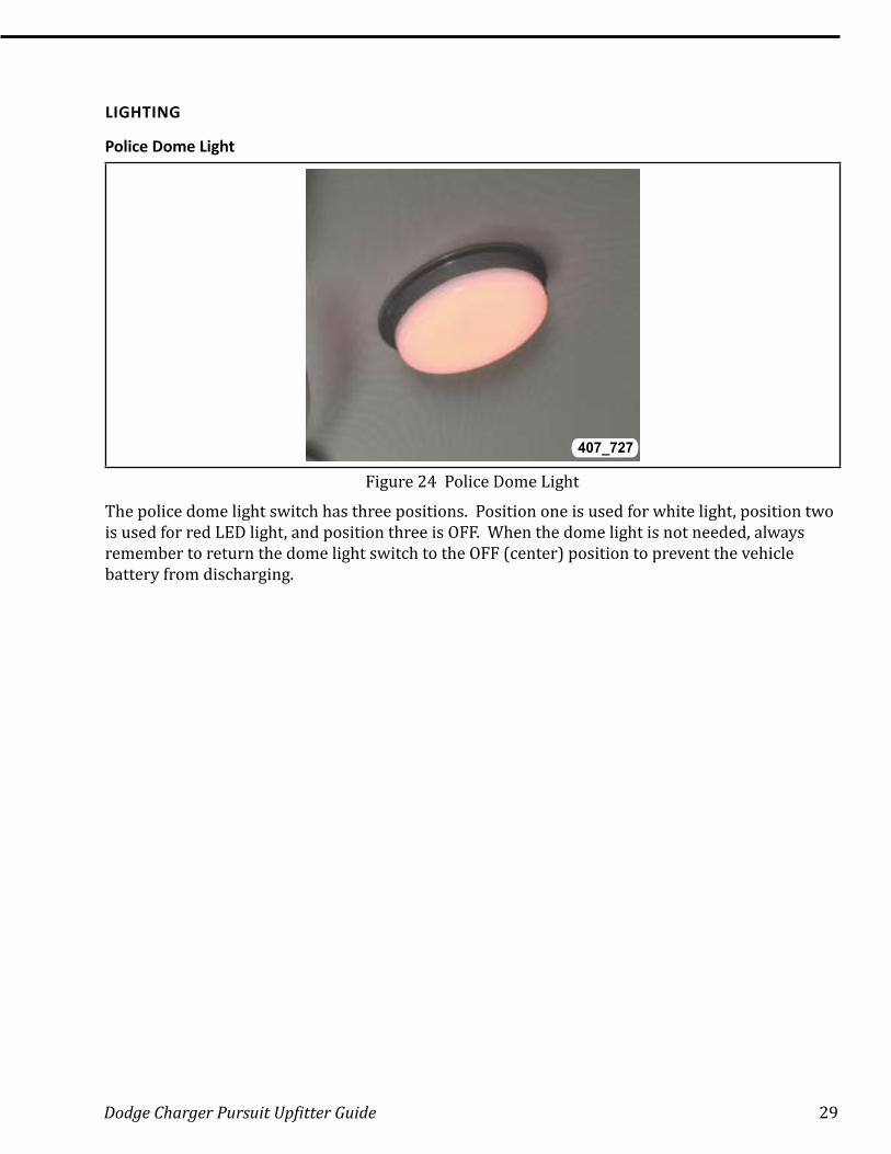
Police Dome Light
407_727
Figure 24 Police Dome Light
The police dome light switch has three positions. Position one is used for white light, position two is used for red LED light, and position three is OFF. When the dome light is not needed, always remember to return the dome light switch to the OFF (center) position to prevent the vehicle battery from discharging.
30 Dodge Charger Pursuit Upfitter Guide
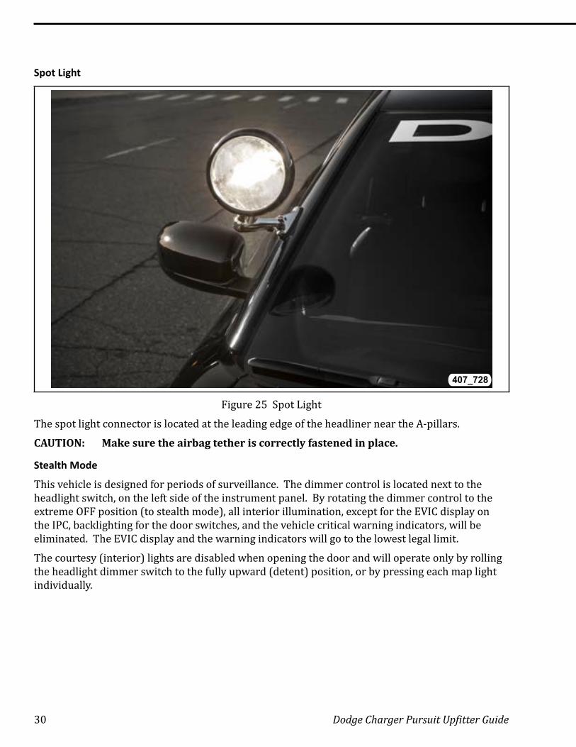
Spot Light
407_728
Figure 25 Spot Light
The spot light connector is located at the leading edge of the headliner near the A-pillars.
CAUTION: Make sure the airbag tether is correctly fastened in place.
Stealth Mode
This vehicle is designed for periods of surveillance. The dimmer control is located next to the headlight switch, on the left side of the instrument panel. By rotating the dimmer control to the extreme OFF position (to stealth mode), all interior illumination, except for the EVIC display on the IPC, backlighting for the door switches, and the vehicle critical warning indicators, will be eliminated. The EVIC display and the warning indicators will go to the lowest legal limit.
The courtesy (interior) lights are disabled when opening the door and will operate only by rolling the headlight dimmer switch to the fully upward (detent) position, or by pressing each map light individually.
Dodge Charger Pursuit Upfitter Guide 31
FUSES
Wiring provisions
The wiring take outs and connections are in similar locations as previous models. Refer to the current Charger Police Vehicle Upfitting Guide for 2006 to 2010 vehicles.
POWER DISTRIBUTION CENTER
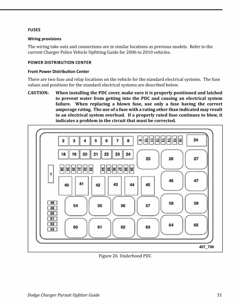
Front Power Distribution Center
There are two fuse and relay locations on the vehicle for the standard electrical systems. The fuse values and positions for the standard electrical systems are described below.
CAUTION: When installing the PDC cover, make sure it is properly positioned and latched to prevent water from getting into the PDC and causing an electrical system failure. When replacing a blown fuse, use only a fuse having the correct amperage rating. The use of a fuse with a rating other than indicated may result in an electrical system overload. If a properly rated fuse continues to blow, it indicates a problem in the circuit that must be corrected.
407_706
Figure 26 Underhood PDC

32 Dodge Charger Pursuit Upfitter Guide
Table 6 Underhood Fuses and Relays
Cavity Cartridge Fuse Mini-fuse Description1 Spare2 40 Radiator Fan 13 50 Power Steering 14 30 Starter5 20 Antilock Brakes6 Spare7 20 Police Ignition Feed 18 20 Police Ignition Feed 29 Spare10 10 Underhood Lamp11 20 Horns12 10 A/C Clutch13 Spare14 25 Antilock Brakes15 Spare16 Spare18 50 Radiator Fan 219 50 Power Steering 220 30 Wiper Motor21 20 Police Battery Feed 322 20 Police Battery Feed 223 20 Police Battery Feed 124 20 Police Ignition Feed 328 25 Fuel Pump29 15 Transmission30 Spare31 25 Engine Module32 Spare33 Spare34 25 ASD Feed 135 20 ASD Feed 236 10 Antilock Brake Module37 10 Engine Control/Fan38 10 Airbag Module39 10 Power Steering Module/A/C Clutch48 Spare
Dodge Charger Pursuit Upfitter Guide 33
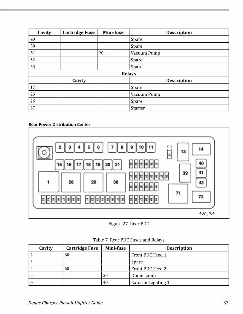
Cavity Cartridge Fuse Mini-fuse Description49 Spare50 Spare51 20 Vacuum Pump52 Spare53 Spare
RelaysCavity Description
17 Spare25 Vacuum Pump26 Spare27 Starter
Rear Power Distribution Center
407_704
Figure 27 Rear PDC
Table 7 Rear PDC Fuses and Relays
Cavity Cartridge Fuse Mini-fuse Description2 60 Front PDC Feed 13 Spare4 60 Front PDC Feed 25 20 Dome Lamp6 40 Exterior Lighting 1

34 Dodge Charger Pursuit Upfitter Guide
Cavity Cartridge Fuse Mini-fuse Description7 40 Exterior Lighting 28 30 Interior Lighting/Washer Pump9 30 Power Locks10 30 Driver Door11 30 Passenger Door12 20 Power Outlets (selectable)15 40 HVAC Blower16 Spare17 Spare18 Spare19 Spare20 Spare21 Spare22 20 Right Spot Lamp23 10 Fuel Door/Diagnostic Port24 15 Radio Screen25 10 Tire Pressure Monitor26 Spare27 Spare31 25 Power Seats32 15 HVAC Module/Cluster33 15 Ignition Switch/Wireless Module34 10 Steering Column Module/Police Module35 10 Battery Sensor36 20 Left Spot Lamp37 15 Radio38 Spare40 Spare41 Spare42 30 Rear Defrost43 Spare44 Spare45 15 Cluster/Rearview Mirror46 Spare47 Spare48 Spare49 Spare
Dodge Charger Pursuit Upfitter Guide 35
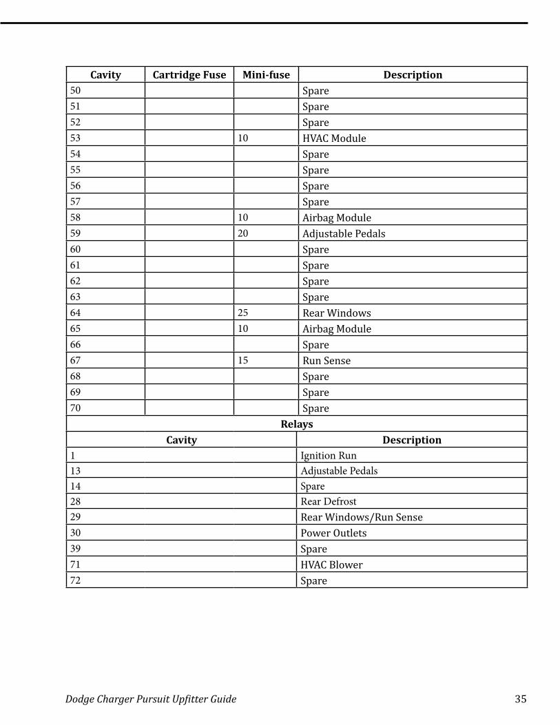
Cavity Cartridge Fuse Mini-fuse Description50 Spare51 Spare52 Spare53 10 HVAC Module54 Spare55 Spare56 Spare57 Spare58 10 Airbag Module59 20 Adjustable Pedals60 Spare61 Spare62 Spare63 Spare64 25 Rear Windows65 10 Airbag Module66 Spare67 15 Run Sense68 Spare69 Spare70 Spare
RelaysCavity Description
1 Ignition Run13 Adjustable Pedals14 Spare28 Rear Defrost29 Rear Windows/Run Sense30 Power Outlets39 Spare71 HVAC Blower72 Spare
36 Dodge Charger Pursuit Upfitter Guide
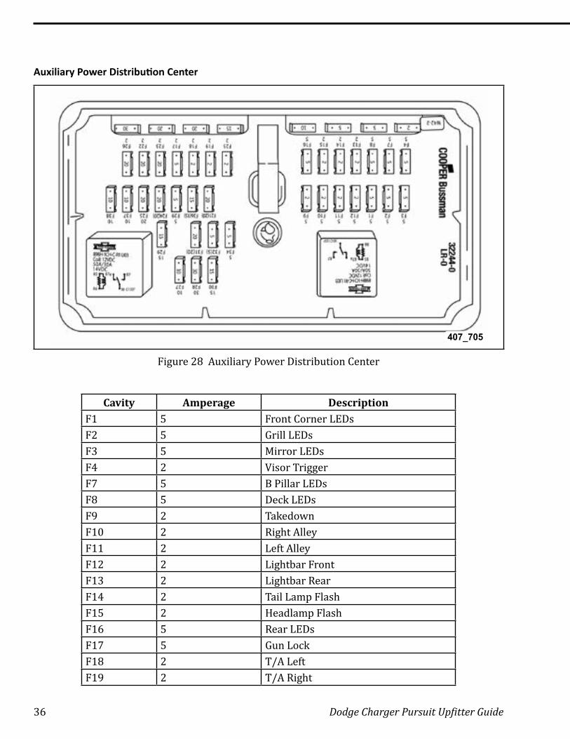
Auxiliary Power Distribution Center
407_705
Figure 28 Auxiliary Power Distribution Center
Cavity Amperage DescriptionF1 5 Front Corner LEDsF2 5 Grill LEDsF3 5 Mirror LEDsF4 2 Visor TriggerF7 5 B Pillar LEDsF8 5 Deck LEDsF9 2 TakedownF10 2 Right AlleyF11 2 Left Alley F12 2 Lightbar FrontF13 2 Lightbar RearF14 2 Tail Lamp FlashF15 2 Headlamp FlashF16 5 Rear LEDsF17 5 Gun LockF18 2 T/A LeftF19 2 T/A Right
Dodge Charger Pursuit Upfitter Guide 37
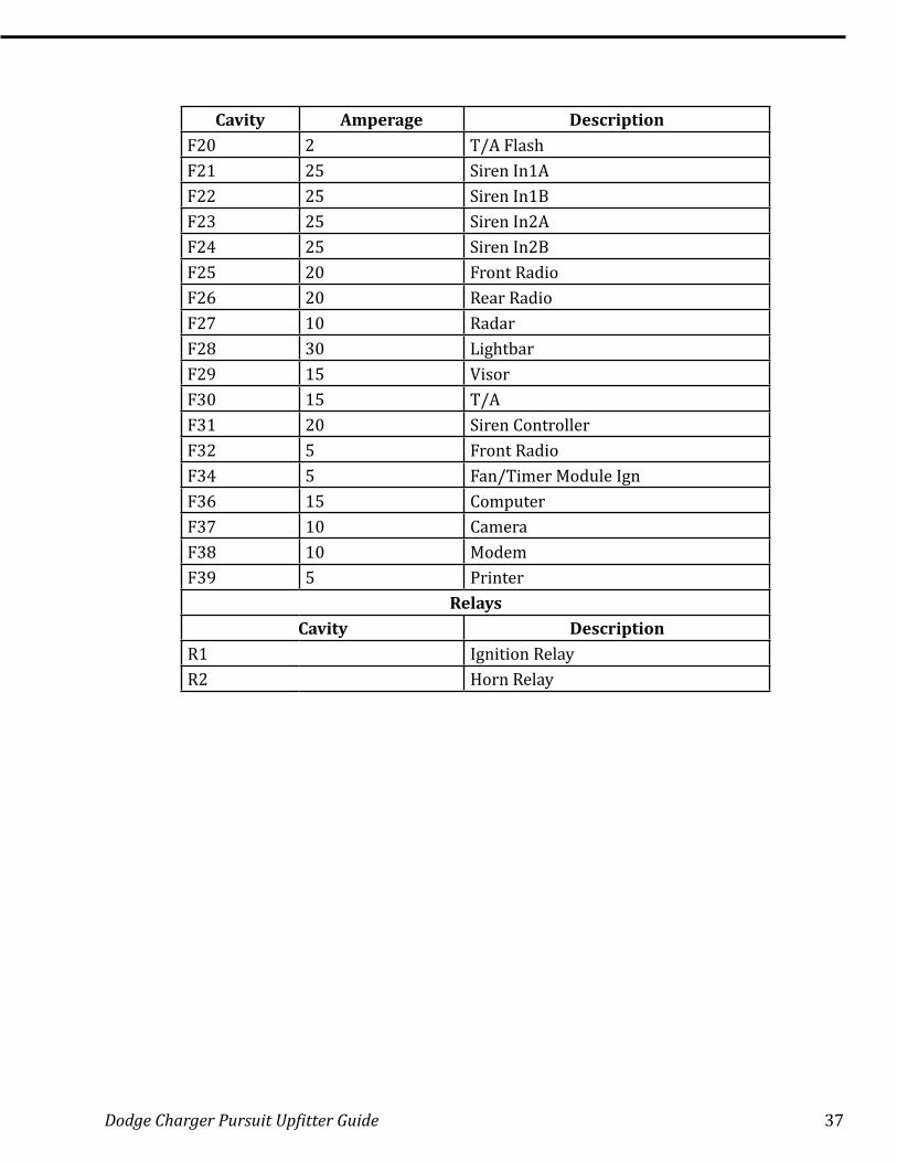
Cavity Amperage DescriptionF20 2 T/A FlashF21 25 Siren In1AF22 25 Siren In1BF23 25 Siren In2AF24 25 Siren In2BF25 20 Front RadioF26 20 Rear RadioF27 10 RadarF28 30 LightbarF29 15 VisorF30 15 T/AF31 20 Siren ControllerF32 5 Front RadioF34 5 Fan/Timer Module IgnF36 15 ComputerF37 10 CameraF38 10 ModemF39 5 Printer
RelaysCavity Description
R1 Ignition RelayR2 Horn Relay
38 Dodge Charger Pursuit Upfitter Guide
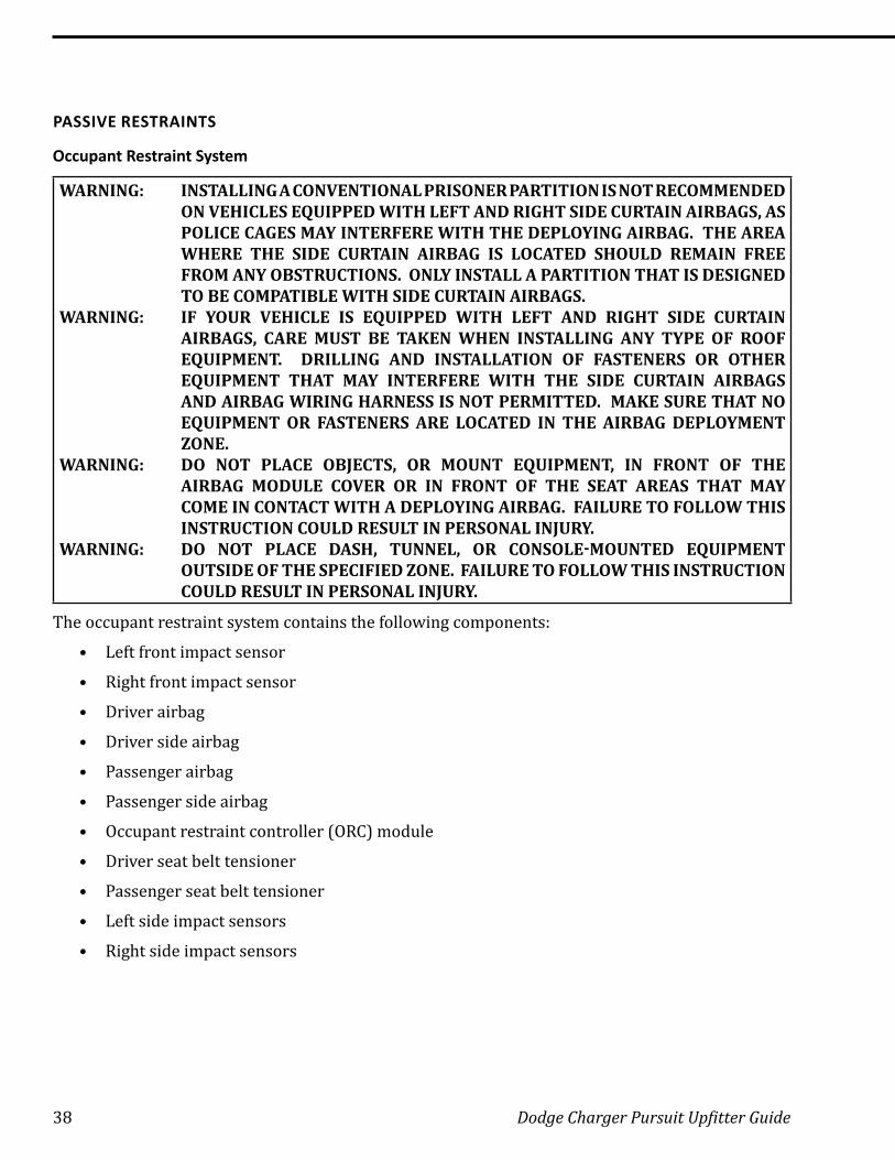
PASSIVE RESTRAINTS
Occupant Restraint System
WARNING: INSTALLING A CONVENTIONAL PRISONER PARTITION IS NOT RECOMMENDED ON VEHICLES EQUIPPED WITH LEFT AND RIGHT SIDE CURTAIN AIRBAGS, AS POLICE CAGES MAY INTERFERE WITH THE DEPLOYING AIRBAG. THE AREA WHERE THE SIDE CURTAIN AIRBAG IS LOCATED SHOULD REMAIN FREE FROM ANY OBSTRUCTIONS. ONLY INSTALL A PARTITION THAT IS DESIGNED TO BE COMPATIBLE WITH SIDE CURTAIN AIRBAGS.
WARNING: IF YOUR VEHICLE IS EQUIPPED WITH LEFT AND RIGHT SIDE CURTAIN AIRBAGS, CARE MUST BE TAKEN WHEN INSTALLING ANY TYPE OF ROOF EQUIPMENT. DRILLING AND INSTALLATION OF FASTENERS OR OTHER EQUIPMENT THAT MAY INTERFERE WITH THE SIDE CURTAIN AIRBAGS AND AIRBAG WIRING HARNESS IS NOT PERMITTED. MAKE SURE THAT NO EQUIPMENT OR FASTENERS ARE LOCATED IN THE AIRBAG DEPLOYMENT ZONE .
WARNING: DO NOT PLACE OBJECTS, OR MOUNT EQUIPMENT, IN FRONT OF THE AIRBAG MODULE COVER OR IN FRONT OF THE SEAT AREAS THAT MAY COME IN CONTACT WITH A DEPLOYING AIRBAG. FAILURE TO FOLLOW THIS INSTRUCTION COULD RESULT IN PERSONAL INJURY.
WARNING: DO NOT PLACE DASH, TUNNEL, OR CONSOLE-MOUNTED EQUIPMENT OUTSIDE OF THE SPECIFIED ZONE. FAILURE TO FOLLOW THIS INSTRUCTION COULD RESULT IN PERSONAL INJURY.
The occupant restraint system contains the following components:
• Left front impact sensor
• Right front impact sensor
• Driver airbag
• Driver side airbag
• Passenger airbag
• Passenger side airbag
• Occupant restraint controller (ORC) module
• Driver seat belt tensioner
• Passenger seat belt tensioner
• Left side impact sensors
• Right side impact sensors
Dodge Charger Pursuit Upfitter Guide 39
There are four interior zones to be aware of:
• Driver airbag deployment zone
• Passenger airbag deployment zone
• Side curtain airbags deployment zone
• Side airbags (seat-mounted) deployment zone
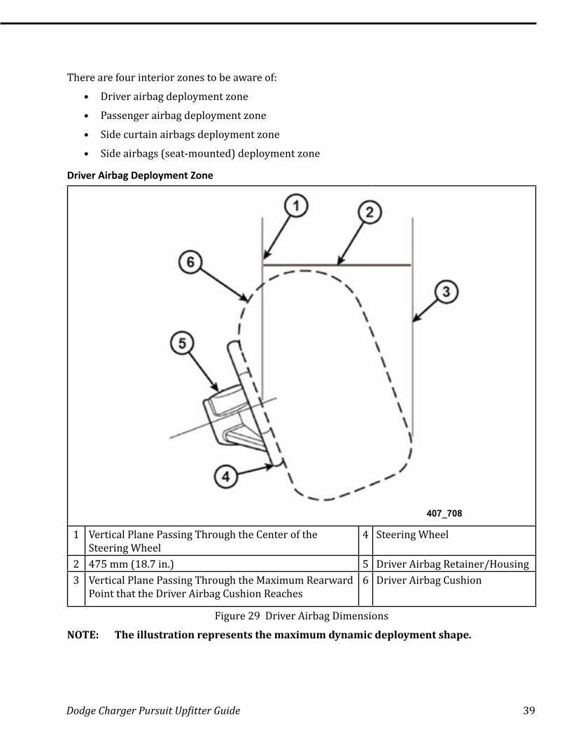
Driver Airbag Deployment Zone
407_708
1 Vertical Plane Passing Through the Center of the Steering Wheel
4 Steering Wheel
2 475 mm (18 .7 in .) 5 Driver Airbag Retainer/Housing3 Vertical Plane Passing Through the Maximum Rearward
Point that the Driver Airbag Cushion Reaches6 Driver Airbag Cushion
Figure 29 Driver Airbag Dimensions
NOTE: The illustration represents the maximum dynamic deployment shape.
40 Dodge Charger Pursuit Upfitter Guide
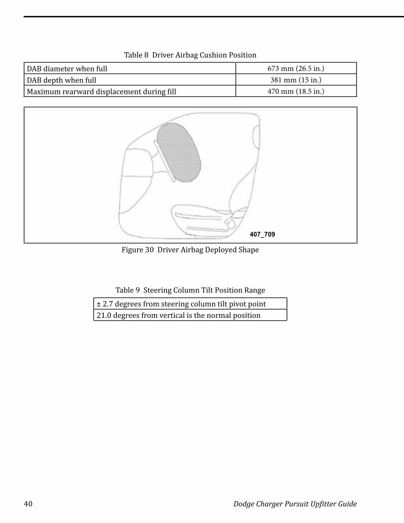
Table 8 Driver Airbag Cushion Position
DAB diameter when full 673 mm (26.5 in.)DAB depth when full 381 mm (15 in.)Maximum rearward displacement during fill 470 mm (18.5 in.)
407_709
Figure 30 Driver Airbag Deployed Shape
Table 9 Steering Column Tilt Position Range
± 2.7 degrees from steering column tilt pivot point21.0 degrees from vertical is the normal position
Dodge Charger Pursuit Upfitter Guide 41
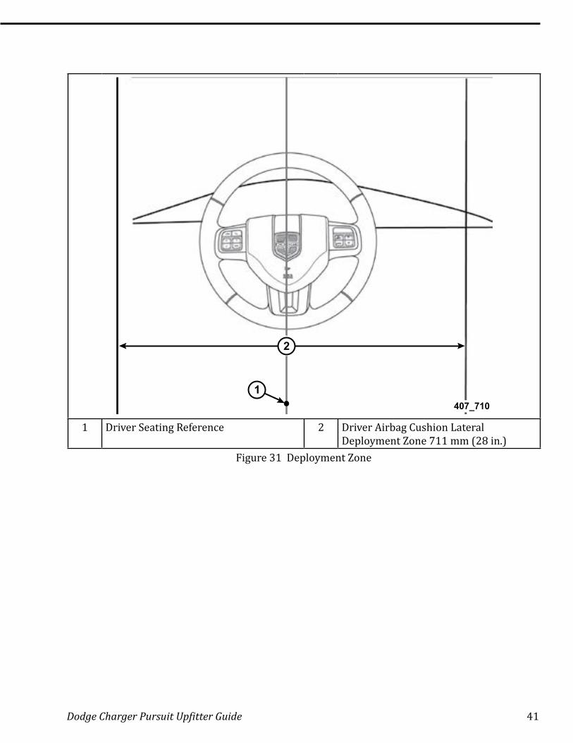
2
1407_710
1 Driver Seating Reference 2 Driver Airbag Cushion Lateral Deployment Zone 711 mm (28 in.)
Figure 31 Deployment Zone
42 Dodge Charger Pursuit Upfitter Guide
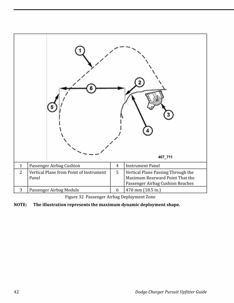
407_711
1 Passenger Airbag Cushion 4 Instrument Panel2 Vertical Plane from Point of Instrument
Panel5 Vertical Plane Passing Through the
Maximum Rearward Point That the Passenger Airbag Cushion Reaches
3 Passenger Airbag Module 6 470 mm (18 .5 in .)Figure 32 Passenger Airbag Deployment Zone
NOTE: The illustration represents the maximum dynamic deployment shape.
Dodge Charger Pursuit Upfitter Guide 43
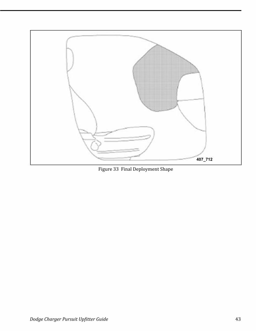
407_712
Figure 33 Final Deployment Shape
44 Dodge Charger Pursuit Upfitter Guide
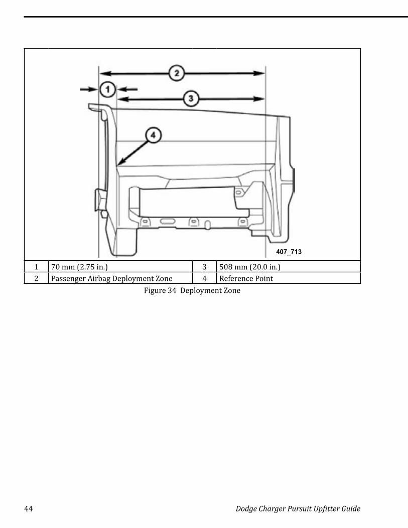
407_713
1 70 mm (2 .75 in .) 3 508 mm (20 .0 in .)2 Passenger Airbag Deployment Zone 4 Reference Point
Figure 34 Deployment Zone
Dodge Charger Pursuit Upfitter Guide 45
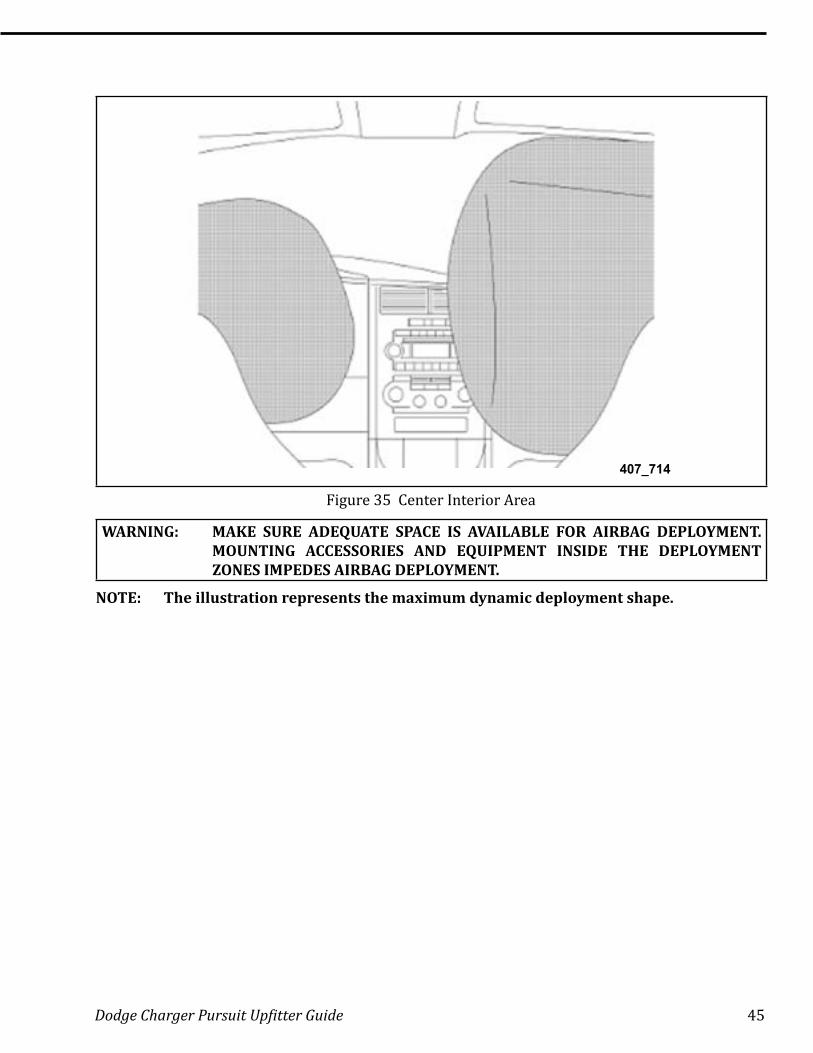
407_714
Figure 35 Center Interior Area
WARNING: MAKE SURE ADEQUATE SPACE IS AVAILABLE FOR AIRBAG DEPLOYMENT. MOUNTING ACCESSORIES AND EQUIPMENT INSIDE THE DEPLOYMENT ZONES IMPEDES AIRBAG DEPLOYMENT.
NOTE: The illustration represents the maximum dynamic deployment shape.

46 Dodge Charger Pursuit Upfitter Guide
Side Curtain Airbag Deployment Zone
407_715
1 Cross Sectional Area Side View 7 88 .9 mm (3 .5 in .)2 220 .9 mm (8 .7 in .) 8 368 .3 mm (14 .5 in .)3 88 .9 mm (3 .5 in .) 9 482 .6 mm (16 .0 in .)4 449 .6 mm (17 .7 in .) 10 B-pillar5 1033 .8 mm (40 .7 in .) 11 Side Curtain Airbag Inflator Module6 502 .9 mm (19 .8 in .) 12 88 .9 mm (3 .5 in .)
Figure 36 Side Curtain Airbag Deployment Zone
WARNING: MAKE SURE ADEQUATE SPACE IS AVAILABLE FOR AIRBAG DEPLOYMENT. DO NOT MOUNT EQUIPMENT OR ROUTE WIRES IN A WAY THAT WILL IMPEDE SIDE CURTAIN AIRBAG DEPLOYMENT.
If the vehicle is equipped with side curtain airbags, take care when installing equipment in the roof area to avoid drilling or installing fasteners in the side curtain airbag area. Also make sure that no equipment installed inside the vehicle interferes with the airbag deployment areas. If additional wiring needs to be routed on the sides of the roof, take care that the installed harness does not impede the airbag deployment. Point fasteners used to attach roof-mounted equipment outward from the passenger compartment to minimize risk of head injury and to avoid altering the head impact protection system (FMVSS 201) that is standard on these vehicles. Do not allow fasteners to extend into the passenger compartment, even between the roof and headliner.
Dodge Charger Pursuit Upfitter Guide 47
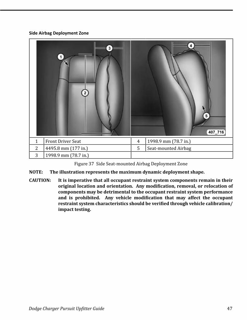
Side Airbag Deployment Zone
407_716
1 Front Driver Seat 4 1998 .9 mm (78 .7 in .)2 4495 .8 mm (177 in .) 5 Seat-mounted Airbag3 1998 .9 mm (78 .7 in .)
Figure 37 Side Seat-mounted Airbag Deployment Zone
NOTE: The illustration represents the maximum dynamic deployment shape.
CAUTION: It is imperative that all occupant restraint system components remain in their original location and orientation. Any modification, removal, or relocation of components may be detrimental to the occupant restraint system performance and is prohibited. Any vehicle modification that may affect the occupant restraint system characteristics should be verified through vehicle calibration/impact testing.

48 Dodge Charger Pursuit Upfitter Guide
Occupant Restraint System Wiring
All occupant restraint system wiring must remain intact and may not be used for any other purpose. This includes the driver and front passenger seat wiring. Any electrical connector that is yellow is part of the occupant restraint system and should not be modified or used for other purposes.
Occupant Restraint System Verification
After any modification work is complete, confirm the occupant restraint system readiness as follows: turn the ignition key to the ON position. The airbag lamp in the instrument cluster illuminates for 6 to 8 seconds, and then turns off. If the airbag lamp fails to illuminate, repeatedly cycles on and off, or does not turn off, have the condition corrected by an authorized Chrysler LLC dealership before shipping the vehicle to the customer.
Dodge Charger Pursuit Upfitter Guide 49
TOWING
Chrysler Group LLC does not recommend towing with the Dodge Charger Pursuit vehicle.
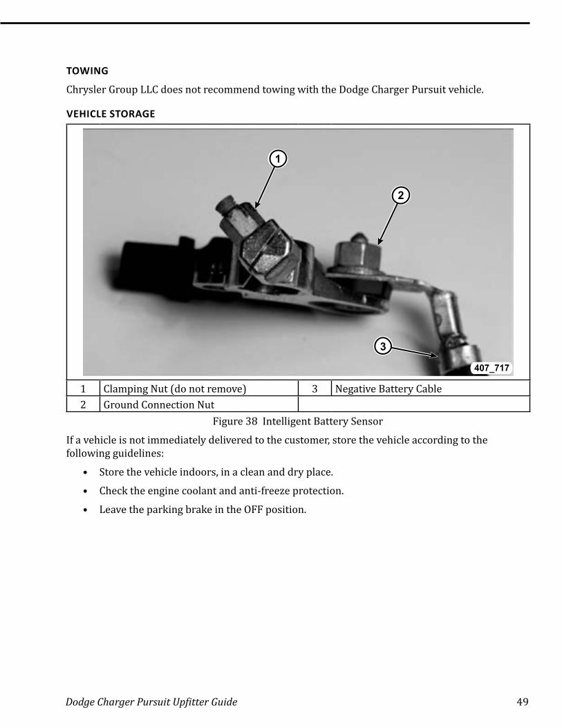
VEHICLE STORAGE
1
3
2
407_717
1 Clamping Nut (do not remove) 3 Negative Battery Cable2 Ground Connection Nut
Figure 38 Intelligent Battery Sensor
If a vehicle is not immediately delivered to the customer, store the vehicle according to the following guidelines:
• Store the vehicle indoors, in a clean and dry place.
• Check the engine coolant and anti-freeze protection.
• Leave the parking brake in the OFF position.
50 Dodge Charger Pursuit Upfitter Guide
If vehicles must be stored outside:
• Avoid storage locations near obvious sources of industrial or environmental contamination (such as trees, factories, steam or vapor vents, railroad tracks, etc.).
• Maintain tight security to help prevent vandalism. Inspect the vehicle regularly to check for such damage.
• If the vehicle must be parked on an incline, park it with the front end higher than the rear. This prevents hydrostatic lock caused by fuel draining into the engine.
• Rinse the vehicle at least once a week. Wash away the snow more often because it can trap harmful contaminants . Dry all horizontal surfaces .
• Remove the negative battery cable by removing the ground connection nut to prevent battery drain and possible damage.
• Keep all windows closed, all doors locked, and all trim covers intact and in place.
• Do not use chalk, crayon, or any marker containing abrasives on painted, plated, or glass surfaces .
• Use protective, thin, plastic film to avoid soiling seats when moving a vehicle.
NOTE: The 2011 and newer Dodge Charger Pursuit vehicle does not have an IOD fuse as in previous models. Therefore, the negative battery cable should be removed from the intelligent battery sensor to prevent draining the battery during extended vehicle storage. Only loosen the ground connection nut from the intelligent battery sensor to remove the negative battery cable.
WARNING: THE BATTERY IN THIS VEHICLE HAS A VENT HOSE THAT SHOULD NOT BE DISCONNECTED AND SHOULD ONLY BE REPLACED WITH A BATTERY OF THE SAME TYPE (VENTED). FAILURE TO FOLLOW THIS WARNING CAN RESULT IN SERIOUS OR FATAL INJURY.
Once a month:
• Check the battery state for charge (at least 12.4 volts). Charge the battery as necessary to help prevent freezing and deterioration.
• Make sure that the battery vent tube is properly connected to the battery and to the floor pan.
• Check the vehicle tire pressures and inflate them to the maximum recommended levels. To help avoid flat spotting, move the vehicle at least once a month so that a different portion of the tire tread contacts the ground.
Dodge Charger Pursuit Upfitter Guide 51
Shipping Mode
The Dodge Charger Pursuit vehicle no longer uses an IOD fuse when transporting or storing for a long period of time. The BCM has a Shipping Mode that takes the place of pulling the IOD fuse. The vehicle will come from the factory in Shipping mode.
2011 - 2014.5 Models
To enable/disable the Shipping Mode function, press and hold the Front Defrost and Enter/Browse for five seconds. You can also enable/disable the vehicle from Shipping Mode by using the scan tool: go to BCM then Misc. function.
2015 - newer
Table 10 Shipping Mode
Description ActionKeep all protective transit film, wheel covers, and films on vehicle
Keep all protective transit film, wheel covers, and films on vehicle until sold .
Inflate the tire pressure to the maximum side wall pressure
Inflate the tire pressure to the maximum side wall pressure (except heavy duty trucks).
Put the vehicle into Ship Mode (if no IOD fuse)
Simultaneously press the Front Defrost and Enter/Browse buttons and hold five seconds. The EVIC display will update once the vehicle goes into Shipping Mode.
52 Dodge Charger Pursuit Upfitter Guide
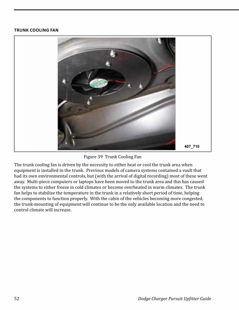
TRUNK COOLING FAN
407_710
Figure 39 Trunk Cooling Fan
The trunk cooling fan is driven by the necessity to either heat or cool the trunk area when equipment is installed in the trunk. Previous models of camera systems contained a vault that had its own environmental controls, but (with the arrival of digital recording) most of these went away. Multi-piece computers or laptops have been moved to the trunk area and this has caused the systems to either freeze in cold climates or become overheated in warm climates. The trunk fan helps to stabilize the temperature in the trunk in a relatively short period of time, helping the components to function properly. With the cabin of the vehicles becoming more congested, the trunk-mounting of equipment will continue to be the only available location and the need to control climate will increase.
Dodge Charger Pursuit Upfitter Guide 53
Decommissioning a Vehicle
407_765
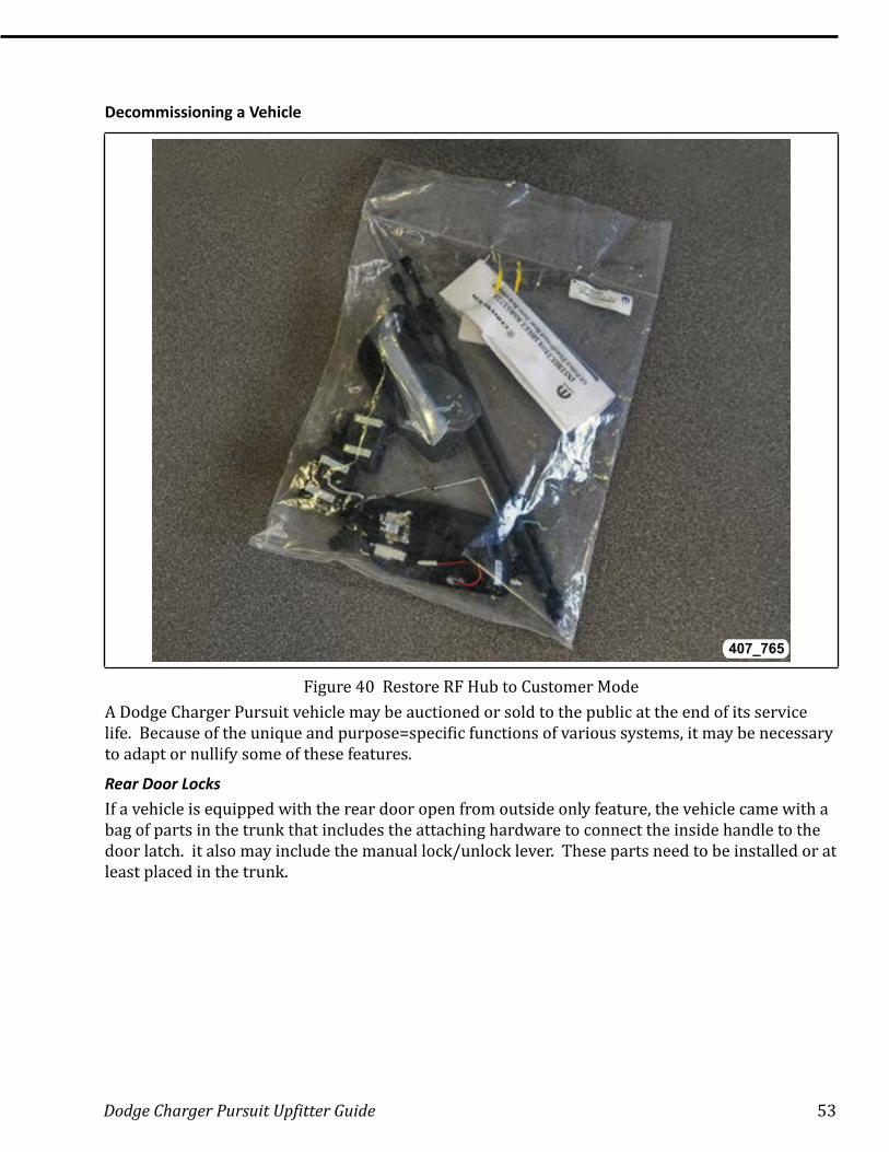
Figure 40 Restore RF Hub to Customer ModeA Dodge Charger Pursuit vehicle may be auctioned or sold to the public at the end of its service life. Because of the unique and purpose=specific functions of various systems, it may be necessary to adapt or nullify some of these features.
Rear Door LocksIf a vehicle is equipped with the rear door open from outside only feature, the vehicle came with a bag of parts in the trunk that includes the attaching hardware to connect the inside handle to the door latch. it also may include the manual lock/unlock lever. These parts need to be installed or at least placed in the trunk.
54 Dodge Charger Pursuit Upfitter Guide
RF Hub Reprogram
The RF Hub controls actuation of the trunk and other remote features. On a police vehicle, using the button located on the trunk-mounted brake lamp only wakes up one of the CAN bus networks and does not open the trunk. This is a function of the Vehicle Configuration for a police vehicle. If the vehicle is equipped with Key Alike, the Disable Key-Alike function should be performed in the RF hub. To perform this function:
• Navigate to the RF Hub using the scan tool
• Select Misc . Functions
• Select Disable Key Alike
Follow the instructions on the screen. The municipality shop may decide to keep the FOBIKS, as they will no longer work with the vehicle.
NOTE: Once the Disable Key Alike function is performed, the FOBIKS will have to be replaced. If a technician attempts to program Key Alike FOBIKs to an RF Hub that has had the Disable Key Alike function performed, the programming will fail. Once the routine has been performed, it cannot be reversed.
Dodge Charger Pursuit Upfitter Guide 55
Ballistic Panels
407_711
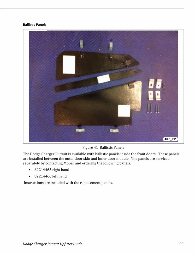
Figure 41 Ballistic Panels
The Dodge Charger Pursuit is available with ballistic panels inside the front doors. These panels are installed between the outer door skin and inner door module. The panels are serviced separately by contacting Mopar and ordering the following panels:
• 82214465 right hand
• 82214466 left hand
Instructions are included with the replacement panels.

56 Dodge Charger Pursuit Upfitter Guide
Notes: ���������������������������������������������������������������������������������������������������������
����������������������������������������������������������������������������������������������������������������
����������������������������������������������������������������������������������������������������������������
����������������������������������������������������������������������������������������������������������������
����������������������������������������������������������������������������������������������������������������
����������������������������������������������������������������������������������������������������������������
����������������������������������������������������������������������������������������������������������������
����������������������������������������������������������������������������������������������������������������
����������������������������������������������������������������������������������������������������������������
����������������������������������������������������������������������������������������������������������������
����������������������������������������������������������������������������������������������������������������
����������������������������������������������������������������������������������������������������������������
����������������������������������������������������������������������������������������������������������������
����������������������������������������������������������������������������������������������������������������
����������������������������������������������������������������������������������������������������������������
����������������������������������������������������������������������������������������������������������������
����������������������������������������������������������������������������������������������������������������
����������������������������������������������������������������������������������������������������������������
����������������������������������������������������������������������������������������������������������������
����������������������������������������������������������������������������������������������������������������
����������������������������������������������������������������������������������������������������������������
����������������������������������������������������������������������������������������������������������������
����������������������������������������������������������������������������������������������������������������
����������������������������������������������������������������������������������������������������������������
����������������������������������������������������������������������������������������������������������������

WORLDWIDEThe special service tools referred to herein are required for certain service operations. These special servicetools or their equivalent, if not obtainable through a local source, are available through the following outlet:
Telephone 1-855-298-2687 2801-80th Street Kenosha, WI 53143, U.S.A. FAX 1-855-303-8985

Rev. 03/26/16
2016
No part of this publication may be reproduced, stored in a retrievalsystem or transmitted, in any form or by any means, electronic, mechanical, photocopying, recording, or otherwise, without the prior written permission of Chrysler Group LLC.
Chrysler Group LLCCopyright