2007 styles: an updated guide to the fundamentals 3d 2007 styles updated... · autodesk civil 3d...
TRANSCRIPT

www.autodesk.com/civil3d
AUTODESK®
CIVIL 3D®
2007
Styles: An Updated Guide to the Fundamentals
About the Author: Mark Scacco, PE, is the founder and president of Engineered Efficiency, Inc., providing CAD and GIS training and consulting to design professionals, contractors, and geospatial specialists. He has consulted as a subject matter expert on Autodesk’s infrastructure solutions products, contributed to several courseware titles, and writes regular magazine articles on technology and industry. He received his civil engineering degree from Purdue University and is a member of the American Society of Civil Engineers, the National Society of Professional Engineers, and the Geospatial Information and Technology Association. He can be reached at [email protected].
Note: Special thanks to Nick Zeeben, Engineered Efficiency consultant and Civil 3D Implementation Certified Expert, for his contributions to this white paper.
Contents Introduction ...................................................................................................................... 2 Templates.......................................................................................................................... 2 Hierarchy of Settings ....................................................................................................... 2 Styles................................................................................................................................. 4
Object Styles ................................................................................................................ 4 Label Styles .................................................................................................................. 9 Table Styles................................................................................................................ 20
Recommended Workflow............................................................................................... 21 Conclusion...................................................................................................................... 23

AUTODESK CIVIL 3D STYLES: AN UPDATED GUIDE TO THE FUNDAMENTALS
www.autodesk.com/civil3d 2
Introduction Autodesk® Civil 3D® software is a state-of-the-art design and drafting application from Autodesk. Built on the familiar AutoCAD® software drawing environment, Civil 3D extends the tools and features available to surveyors, engineers, and drafters, enabling them to create dynamically linked models of proposed and existing project elements.
In the simplest terms, dynamically linked models are related entities within a drawing that automatically update when changes are made to any of the entities. These entities include drawing objects that constitute the model itself (such as digital terrain models, alignments, and corridors) and the annotation or labels associated with the objects. The appearance and behavior of these objects and labels are controlled by styles. Through styles, Civil 3D users have great flexibility in the presentation of design elements. To get the most from Civil 3D, users can create customized styles, which, along with various other drawing settings, can be saved in a drawing template file (DWT) for easy reuse. This paper gives an overview of the various settings used to control drawing content, explains how styles fit into the hierarchy of settings, and describes how to get started with customized styles.
Templates To help users get up and running quickly, Civil 3D comes with six industry-specific drawing templates, three using metric units and three using imperial units. The templates are as follows:
• Autodesk Civil 3D NCS Extended
• Autodesk Civil 3D NCS Classic
• Autodesk Civil 3D NCS Base
All three templates use the National CAD Standard (NCS) for their layer naming convention. The NCS layer naming model (and the stock Civil 3D drawing templates) uses the following format:
<Discipline Designator> - <Major Group> - <Minor Group> - <Status>
Civil 3D uses the C and V Discipline Designators for Civil and Survey/Mapping, respectively. An example of the NCS layer standard for a proposed road alignment would be C-ROAD-CNTR-N. The discipline designator and major group are mandatory and defined in the NCS. The minor group and status are optional and user definable. The base template contains a basic style for each object type in Civil 3D. The extended template contains a more extensive set of styles for all objects. The classic template contains styles that replicate the look of Autodesk® Land Desktop software profiles, sections, points, and label styles. Any of these templates can be used out of the box or as a running head start on creating a custom template.
Hierarchy of Settings Autodesk Civil 3D uses several different settings arranged in a hierarchical structure to control the display and behavior of drawing objects and their labels. Settings are established globally at the top of the hierarchy through drawing-level settings. Next, style-

AUTODESK CIVIL 3D STYLES: AN UPDATED GUIDE TO THE FUNDAMENTALS
www.autodesk.com/civil3d 3
level settings provide further refinement and control. Finally, object-level settings enable users to apply individual settings to single entities.
At the highest level, drawing-level settings control the different settings for many of the features of newly created objects. The Drawing Settings dialog box shown in Figure 1 is accessed via the Settings tab in the Toolspace by right-clicking an open drawing and then choosing Edit Drawing Settings from the context-sensitive menu. As shown, various tabs control a wide range of drawing settings. The Units and Zone tab sets the drawing units and provides the option of establishing a coordinate system, projection, and data for the drawing. With a zone established, settings on the Transformation tab allow for the application of transformation settings such as sea-level scale factor and rotation.
When working with styles and establishing the behavior and appearance of objects, the Object Layers tab is the most relevant. On this tab users define the default destination layers for newly created objects and optional layer name modifiers. As objects are created, they default to the layer settings established here.
Figure 1. Drawing Settings dialog box.
The Abbreviations tab controls the default abbreviations used in annotating and labeling. The options on the Ambient Settings tab affect the default values when objects are created.
As objects are created in Autodesk Civil 3D, they are automatically assigned different style types: object styles, label styles, or both. These style-level settings represent the second tier of settings in the Civil 3D hierarchy. Users can take advantage of the predefined styles in the previously discussed drawing templates installed with Civil 3D, or they can create custom styles to suit particular needs. Many firms prefer their plans to have a unique look. With other software, this means a lot of manual annotation and labeling, or the use of custom or third-party applications. With style-level settings, users can achieve the same customized look with much less effort. Creation of styles and use of style-level settings are discussed in more detail later in this paper.

AUTODESK CIVIL 3D STYLES: AN UPDATED GUIDE TO THE FUNDAMENTALS
www.autodesk.com/civil3d 4
Although style-level settings often provide adequate control of object appearance and behavior, it sometimes may be necessary to apply specific settings to individual objects. Object-level settings make this possible by enabling the user to override drawing- and style-level settings on a per object basis.
Although the entire hierarchy of setting levels can be used to create a final drawing conforming to specific criteria, the most commonly employed settings are the styles.
Styles Style-level settings (or styles) consist of three different style types: object styles, label styles, and table styles. These style types share common features and also have components unique to the entities to which they apply. The rest of this paper discusses the details of each style type and the recommended workflow for using styles.
Object Styles Object styles control the display and design characteristics of an object. When the user creates an object, the software applies a style to that object. Autodesk Civil 3D ships with a predefined style, named “Standard,” for each type of Civil 3D object. Many other predefined styles can be found in the sample templates included with the software. Although these styles may be suitable for certain applications, many users require styles customized to meet their specific needs.
The Settings tab of the Toolspace contains collections of styles for various entity types, such as surfaces, points, and alignments. Let’s use the alignment style as an example for creating a new object style. To easily create a unique object style, simply start with a copy of an existing style and then edit its properties as needed. Right-clicking the Standard object style and choosing Copy from the context-sensitive menu displays the dialog box shown in Figure 2, which is used to modify (or create) an object style.
Figure 2. Alignment Style dialog box.
AUTODESK CIVIL 3D STYLES: AN UPDATED GUIDE TO THE FUNDAMENTALS
www.autodesk.com/civil3d 5
Many of the object-style settings are the same regardless of the object type, but each object type also has unique settings. For example, all objects have settings for Information, Display, and Summary, but alignment objects have an additional setting for Design. Let’s examine each tab to understand how to create a custom object style.
The Information tab is where users enter a name and an optional description for the style. In this example, the style name has been changed to Major Road Alignment.
For alignments, the Design tab is quite simple, with one setting for modifying grip-edit behavior.
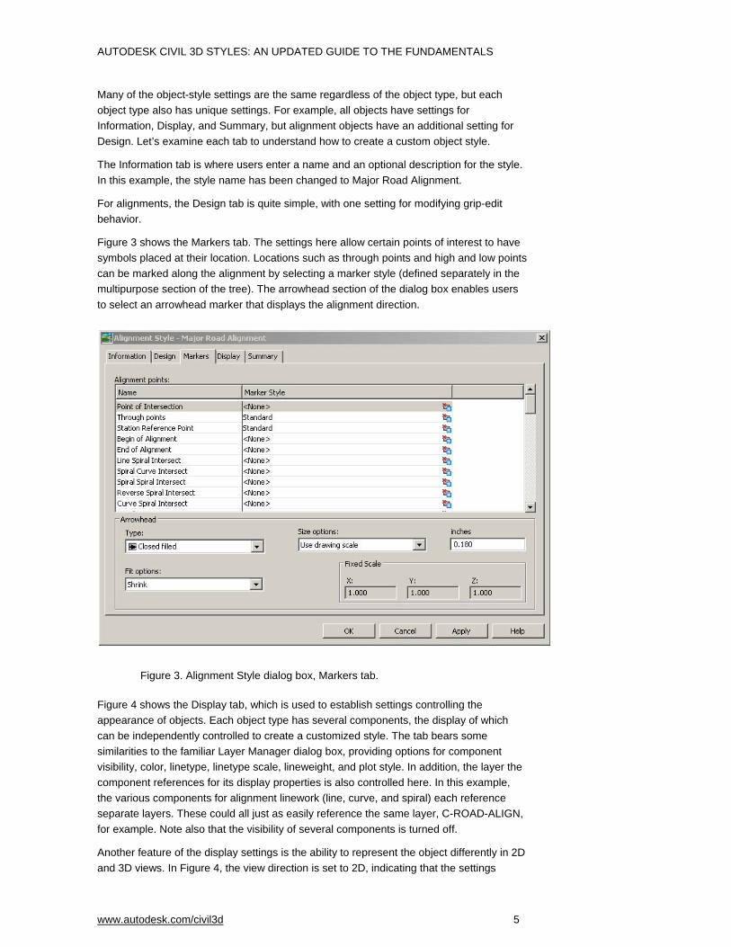
Figure 3 shows the Markers tab. The settings here allow certain points of interest to have symbols placed at their location. Locations such as through points and high and low points can be marked along the alignment by selecting a marker style (defined separately in the multipurpose section of the tree). The arrowhead section of the dialog box enables users to select an arrowhead marker that displays the alignment direction.
Figure 3. Alignment Style dialog box, Markers tab.
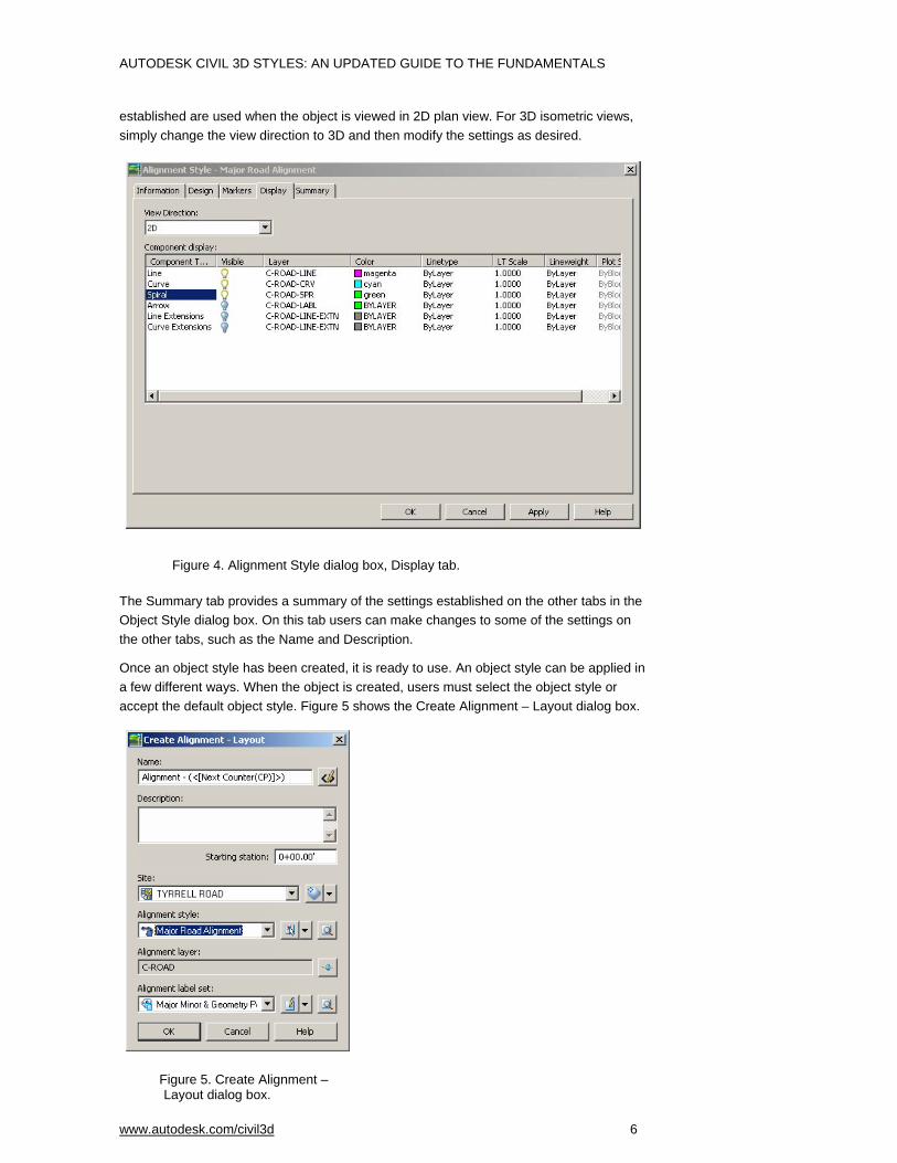
Figure 4 shows the Display tab, which is used to establish settings controlling the appearance of objects. Each object type has several components, the display of which can be independently controlled to create a customized style. The tab bears some similarities to the familiar Layer Manager dialog box, providing options for component visibility, color, linetype, linetype scale, lineweight, and plot style. In addition, the layer the component references for its display properties is also controlled here. In this example, the various components for alignment linework (line, curve, and spiral) each reference separate layers. These could all just as easily reference the same layer, C-ROAD-ALIGN, for example. Note also that the visibility of several components is turned off.
Another feature of the display settings is the ability to represent the object differently in 2D and 3D views. In Figure 4, the view direction is set to 2D, indicating that the settings
AUTODESK CIVIL 3D STYLES: AN UPDATED GUIDE TO THE FUNDAMENTALS
www.autodesk.com/civil3d 6
established are used when the object is viewed in 2D plan view. For 3D isometric views, simply change the view direction to 3D and then modify the settings as desired.
Figure 4. Alignment Style dialog box, Display tab.
The Summary tab provides a summary of the settings established on the other tabs in the Object Style dialog box. On this tab users can make changes to some of the settings on the other tabs, such as the Name and Description.
Once an object style has been created, it is ready to use. An object style can be applied in a few different ways. When the object is created, users must select the object style or accept the default object style. Figure 5 shows the Create Alignment – Layout dialog box.
Figure 5. Create Alignment – Layout dialog box.

AUTODESK CIVIL 3D STYLES: AN UPDATED GUIDE TO THE FUNDAMENTALS
www.autodesk.com/civil3d 7
Use the Alignment Style drop-down near the middle of the dialog box to set the object style to be applied to the new alignment. When the alignment is created, it takes on the appearance and design characteristics as defined by the Major Road Alignment. Users have the option of creating a variety of different object styles and then selecting the appropriate style at the time the object is created. Alternatively, users can modify the object’s style at any time after it is created. This is done via the object Properties dialog box accessed from the Toolspace Prospector or by right-clicking the object in the drawing space and choosing Properties from the context-sensitive menu. Figure 6 shows the Alignment Properties dialog box for a sample alignment, Route 45.
Figure 6. Alignment Properties dialog box.
The Information tab shows the current object style for the alignment object. Figure 6 shows the object style for this alignment as “Design Style.” From this tab, users can modify the object style by selecting a previously defined object style from the drop-down menu. Click Apply or OK to apply the new style to the object. The appearance and design characteristics of the object are updated to reflect the newly applied object style settings.
Use object styles to easily and effectively enforce company design and drafting standards. First, create a set of customized object styles, and then edit the feature settings for each object type to set the desired object style as the default. Figure 7 shows the Edit Feature Settings dialog box for alignments. Note the Alignment Style value is set to Major Road Alignment, the custom style created in the earlier example. The drawing is then saved as a template file (DWT) and used when creating new drawing files. Alternatively, make edits to the drawing settings in a predefined template and save it as a new template.

AUTODESK CIVIL 3D STYLES: AN UPDATED GUIDE TO THE FUNDAMENTALS
www.autodesk.com/civil3d 8
Figure 7. Edit Feature Settings dialog box for alignments.
Hint: Use either of the following methods to establish the feature settings for each object type:
• Edit the settings for all alignments that will be created by right-clicking at the top-level setting for an object type. In this case, right-click the Alignment setting to access the feature-level settings for all alignments that are to be created, as shown in Figure 8A.
• Change the command settings for an object to provide greater control over how the object will be created or edited, as shown in Figure 8B. For example, define that all alignments created “by Polyline” would default to a different style and layer than alignments created using the Layout command.
Figure 8A. Edit feature setting for alignments. Figure 8B. Edit command settings.

AUTODESK CIVIL 3D STYLES: AN UPDATED GUIDE TO THE FUNDAMENTALS
www.autodesk.com/civil3d 9
In summary, object styles control the appearance and design characteristics of the objects themselves. Create custom object styles to meet specific needs and use them as the default style for newly created objects. Save these settings in a drawing template for easy reuse.
Label Styles Object styles control settings for objects, and label styles control settings for the annotation and labeling of these objects. The procedures for creating and applying label styles are similar to those for creating object styles. However, the specifics can get more involved. Label styles consist of three key components: general label properties, the layout parameters of the label components, and the dragged state characteristics of the label.
Like object styles, label styles are grouped in collections by object type on the Settings tab of the Toolspace, with different object types having varying Label Styles subfolders. In Figure 9, for example, the alignment label style subfolders are similar to, but not exactly like those for profile label styles. Each object type has label types for the different elements of the object. For alignments, these are Station, Station Offset, Line, Curve, Spiral, and Tangent Intersection. After the various label-style elements have been defined, they can be grouped together in Label Sets for easy assignment to objects.
Autodesk Civil 3D also includes a general note label style, which is located under the Multi-Purpose collection. This label style enables users to create a general-purpose label that does not have an attachment to specific objects, but still maintains the capabilities of an object label such as dynamic text sizing based on viewport scale. Notes can be created for typical engineering notes, such as Not for Construction or soil compaction information. Note label styles are created in the same manner as the other object label styles described next.
Let’s look at an example of creating a label style and label set for an alignment. First, we’ll create a label style for the Major Station, and then a label style for the Minor Station. Last,
Figure 9. Label Styles subfolders for alignments and profiles.

AUTODESK CIVIL 3D STYLES: AN UPDATED GUIDE TO THE FUNDAMENTALS
www.autodesk.com/civil3d 10
we’ll create a label set consisting of these two styles, plus a Geometry Point label style. As with object styles, it’s easiest to create a new label style by copying and then modifying an existing style. Right-clicking the predefined label style named Standard and choosing Copy from the context-sensitive menu opens the Label Style Composer, used to create label styles for every type of label for all object types. Figure 10 shows a portion of the dialog box.
Figure 10. Label Style Composer dialog box.
The Label Style Composer consists of five tabs. The Information tab is where users enter a name and optional description for the label style. It also contains information about when the style was created and modified, and by whom. Label style names should describe what the label will look like. Here, we are creating a customized label for the major stations, named “Custom Major Station.”
The General tab consists of a preview pane and a property editor that adjusts the properties of the label style itself. The first property, Label, controls the text style, visibility (true or false), and the layer of the label’s text elements (Figure 11).
Figure 11. Label Style Composer dialog box, General tab.
The Behavior property helps to define the location and orientation of the label. Typically, the default values shown meet the needs of new users. As the name implies, the Plan

AUTODESK CIVIL 3D STYLES: AN UPDATED GUIDE TO THE FUNDAMENTALS
www.autodesk.com/civil3d 11
Readability property provides settings used to keep text labels oriented as desired in relation to the printed page.
The Layout tab is arguably the most important part of the Label Style Composer. This is where users define the components of the object to be labeled as well as the text labels themselves. This tab consists of a preview pane, a component selector, and a component property editor. Figure 12 shows a portion of the Layout tab.
The steps required to create a label style consist of first creating a component and then modifying the properties of that component. Components can be one of a variety of types, depending on the object to be labeled. For alignments, the label component types are Text, Line, Block, and Tick, and the editable properties vary depending on the component type. Define a component by selecting the appropriate type from the fly-out button, as shown in Figure 13, and then modifying its properties.
Figure 12. Label Style Composer dialog box, Layout tab.
Figure 13. Define a label component type.

AUTODESK CIVIL 3D STYLES: AN UPDATED GUIDE TO THE FUNDAMENTALS
www.autodesk.com/civil3d 12
In this example, there is a single component named Station. This is a text component with three groups of editable properties, General, Text, and Border. The General properties define the name of the component, its visibility, and its anchor component and anchor point. The anchor component defines what the station component of the label is attached to and is either the object itself (the feature) or another component of the label style, such as a line or tick. The anchor point defines the location on the anchor component where the station component is attached. In the example shown in Figure 14, the component named Station is attached to the feature (the alignment) and connects to the alignment at the point on the alignment referred to as the anchor station.
The text properties of a label style are perhaps the most confusing element of a label component. Most of the text properties are straightforward, such as text height, rotation angle, color, lineweight, and so on. These are all familiar properties of regular AutoCAD text entities. The attachment value defines the location on the text itself that connects to the anchor point discussed in the previous paragraph.
The value for contents of the label is a bit more complicated and needs further explanation. To change the contents of the text label, click in the value cell and then click the ellipsis to open the Text Component Editor – Label Text dialog box shown in Figure 15.
Figure 14. Properties of the Station component.

AUTODESK CIVIL 3D STYLES: AN UPDATED GUIDE TO THE FUNDAMENTALS
www.autodesk.com/civil3d 13
Figure 15. Text Component Editor – Label Text dialog box.
The Text Component Editor is the same dialog box used to create label-style text components for all object types (profiles, parcels, alignments, and so forth). The editor consists of three main areas: the text editing area on the right and two tabs, Format and Properties.
The Properties tab contains a drop-down list of all properties of the feature to be labeled. Each property has a list of modifiers whose values can be adjusted to create a customized text label. Figure 15 shows the Station Value property, along with modifiers for unit, format, precision, and so on. To change a modifier value, click in the value cell and then choose the desired settings from the drop-down list. Figure 16 shows the drop-down list used to set the Precision modifier.
Figure 16. Drop-down list used to set the Precision modifier.
Next to the Properties drop-down is a button with a blue arrow. Use this button to apply the modifier values. First, position the cursor at the desired location in the text editor on the right. Next, adjust the modifier values as desired, changing precision, rounding, and so on to meet custom requirements. Finally, apply the adjusted settings by clicking the arrow button. The coding required to display the information about the feature property is inserted into the text editor. Add information manually to the text label component simply

AUTODESK CIVIL 3D STYLES: AN UPDATED GUIDE TO THE FUNDAMENTALS
www.autodesk.com/civil3d 14
by setting the cursor at the desired location in the text editor and typing text. In Figure 17, the text “STA:” was entered manually and the rest of the text was created automatically when the arrow button was pressed.
Figure 17. Enter text in the text editor.
This example demonstrates that users can enter text anywhere in the text editor window simply by typing. Note that the manually added text must not be entered in angled brackets < >, which identify the limits of the automatically generated portion of the text label.
The Format tab controls settings for text formatting. Here, users can modify typical text settings such as Justification, Font, and Color. Text style, however, is set on the General tab and cannot be changed here. See Figure 18.
The border properties of a label (shown in Figure 14) enable users to specify a border surrounding the component being edited. The border properties also enable users to include a background mask. This mask obscures objects that are behind the label, making them readable even when other objects in the view might otherwise make label placement difficult. Figure 19 shows an example of a contour label with background mask set to True and False.
Figure 18. Text Component Editor dialog box.

AUTODESK CIVIL 3D STYLES: AN UPDATED GUIDE TO THE FUNDAMENTALS
www.autodesk.com/civil3d 15
Figure 19. Label with background mask set to True and False.
The addition of background masks requires control over the draw order of the individual label components. Draw order controls the order in which the software draws each component from bottom to top. Typically the masked element is at the bottom of the order, so all other elements in the label are above. Control draw order by clicking the Draw Order button. In the Draw Order dialog box, use the up and down arrows to change the component draw order. Figure 20 shows the Component Draw Order dialog box.
Figure 20. Component Draw Order dialog box.
In addition to text components of a label style, use various other components to define the complete style (see Figure 13). For alignments, add a tick component. From the Component Creation drop-down, select Tick as shown in Figure 21.
Figure 21. Add a tick component for alignments.
AUTODESK CIVIL 3D STYLES: AN UPDATED GUIDE TO THE FUNDAMENTALS
www.autodesk.com/civil3d 16
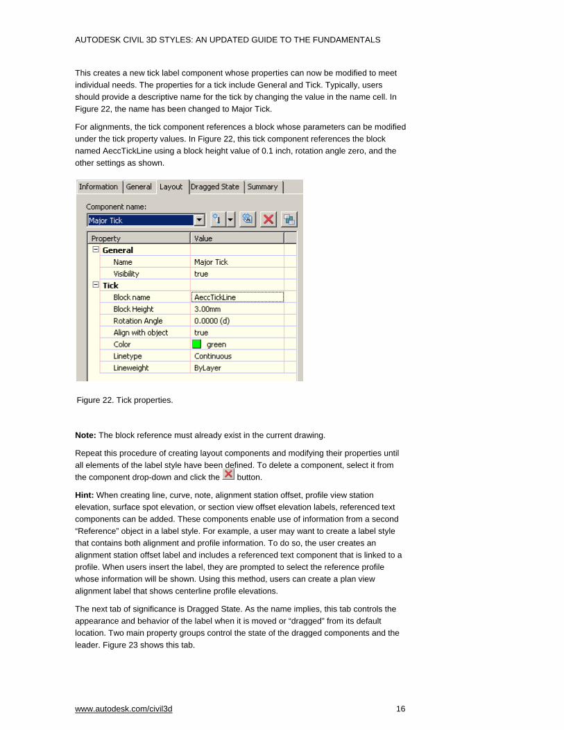
This creates a new tick label component whose properties can now be modified to meet individual needs. The properties for a tick include General and Tick. Typically, users should provide a descriptive name for the tick by changing the value in the name cell. In Figure 22, the name has been changed to Major Tick.
For alignments, the tick component references a block whose parameters can be modified under the tick property values. In Figure 22, this tick component references the block named AeccTickLine using a block height value of 0.1 inch, rotation angle zero, and the other settings as shown.
Note: The block reference must already exist in the current drawing.
Repeat this procedure of creating layout components and modifying their properties until all elements of the label style have been defined. To delete a component, select it from the component drop-down and click the button.
Hint: When creating line, curve, note, alignment station offset, profile view station elevation, surface spot elevation, or section view offset elevation labels, referenced text components can be added. These components enable use of information from a second “Reference” object in a label style. For example, a user may want to create a label style that contains both alignment and profile information. To do so, the user creates an alignment station offset label and includes a referenced text component that is linked to a profile. When users insert the label, they are prompted to select the reference profile whose information will be shown. Using this method, users can create a plan view alignment label that shows centerline profile elevations.
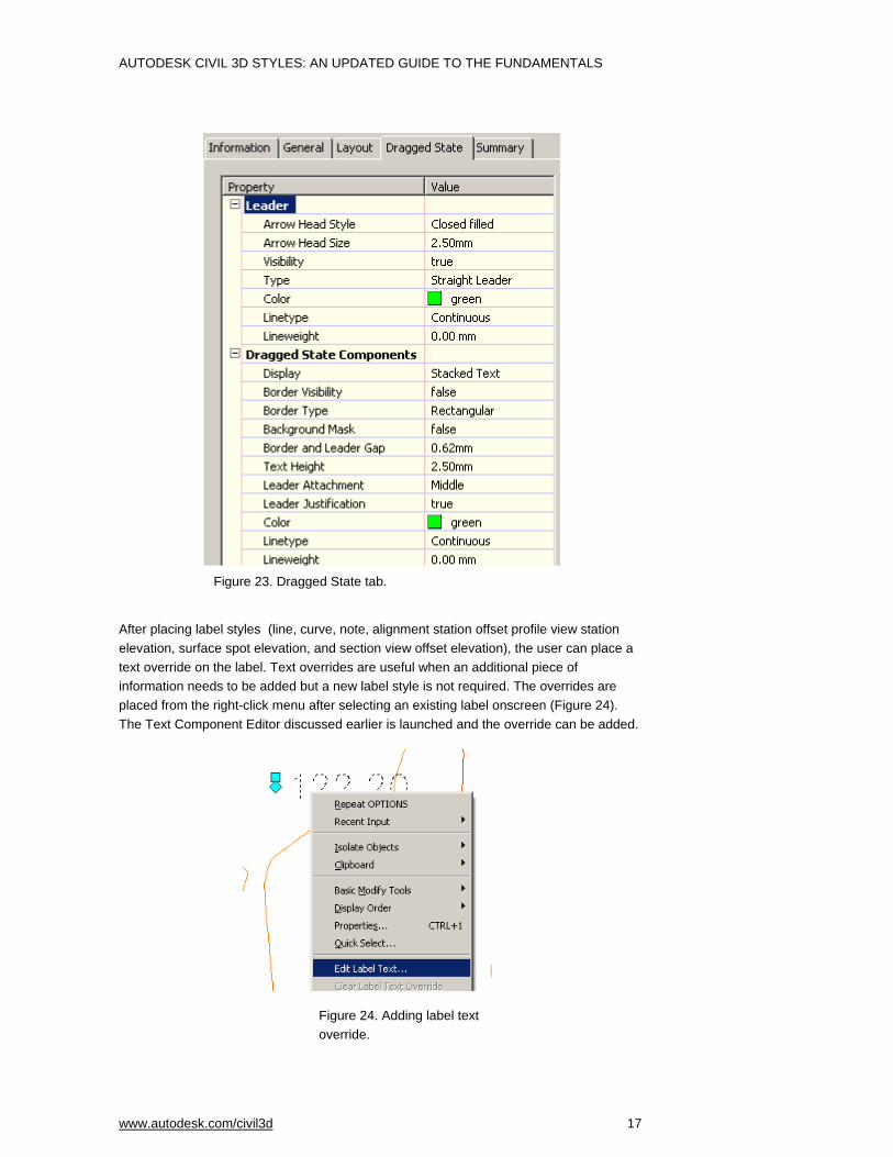
The next tab of significance is Dragged State. As the name implies, this tab controls the appearance and behavior of the label when it is moved or “dragged” from its default location. Two main property groups control the state of the dragged components and the leader. Figure 23 shows this tab.
Figure 22. Tick properties.
AUTODESK CIVIL 3D STYLES: AN UPDATED GUIDE TO THE FUNDAMENTALS
www.autodesk.com/civil3d 17
After placing label styles (line, curve, note, alignment station offset profile view station elevation, surface spot elevation, and section view offset elevation), the user can place a text override on the label. Text overrides are useful when an additional piece of information needs to be added but a new label style is not required. The overrides are placed from the right-click menu after selecting an existing label onscreen (Figure 24). The Text Component Editor discussed earlier is launched and the override can be added.
Figure 23. Dragged State tab.
Figure 24. Adding label text override.

AUTODESK CIVIL 3D STYLES: AN UPDATED GUIDE TO THE FUNDAMENTALS
www.autodesk.com/civil3d 18
Autodesk Civil 3D 2007 includes the ability to create user-defined expressions that can be applied to labels. These expressions enable users to perform mathematical operations on object properties. For example, a user can create an expression that adds a fixed value to the surface elevation being displayed in a label style. If a user created a standard building pad label and also wants to label finished floor elevation, he or she would create an expression as shown in Figure 25. Expressions are created through the Settings tab of Toolspace. Once created, the expression is added to a label style as an object property in the Text Component Editor.
Figure 25. Expressions in Toolspace and New Expression dialog box, Expression in label composer.
Label styles are often grouped together into label sets. It is common to apply more than one label style to an object, such as an alignment label style for major stations and another for minor stations. Grouping label styles into label sets makes it easy to apply multiple styles to an object in one operation instead of having to apply each style individually.
As with creating a new label style, it’s easiest to create a new label set by copying an existing set and then modifying it. Figure 26 shows the Alignment Label Set dialog box. It too has an Information tab where users specify the name and an optional description. The Labels tab is where users add individual label styles to the set and save them for later reuse.

AUTODESK CIVIL 3D STYLES: AN UPDATED GUIDE TO THE FUNDAMENTALS
www.autodesk.com/civil3d 19
Figure 26. Alignment Label Set dialog box.
The various parts of this dialog box are as follows:
Type: The Type drop-down lists each of the Station Label groups: Major Station, Minor Station, Geometry Point, Station Equation, and Design Speed.
Label Style: Select a Type to see the label styles available for that Type in the Label Style drop-down list. In Figure 26 the Label Style drop-down list is called Major Station Label Style. The name of this drop-down changes depending on the Type selected.
Add/Delete: Select the desired Type and Label Style, and then use the button to add the label style to the set. To delete a style from the set, highlight the style in the lower list and click the button. In Figure 26, the label set consists of a Major Station label style named Parallel with Tick, a Minor Station label style named Tick, and a Geometry Point label style named Perpendicular with Tick & Line.
Increment: The Increment setting enables users to define the increment at which the various label styles are applied. For this example, the major is set to 100 feet and the minor to 50 feet. (Geometry Point styles are not applied at increments, but rather at all geometry points such as Point of Curvature and Point of Tangent.)
The process for applying label styles is nearly identical to that for applying object styles. Users can apply them at the time the object is created or after the fact by modifying the object’s properties. Referring back to Figure 5, note that there is an option to establish the label style set at the time the object is created. After objects are created, add label styles individually or in sets from the Labels tab in the object’s Properties dialog box, as shown in Figure 27. Notice this tab is similar to the Label Set Creation dialog box, with the added options of importing a predefined set of label styles and saving the current set of styles for future reuse .

AUTODESK CIVIL 3D STYLES: AN UPDATED GUIDE TO THE FUNDAMENTALS
www.autodesk.com/civil3d 20
Figure 27. Alignment Properties dialog box.
A great timesaving feature of label styles is their ability to maintain their scale and orientation regardless of the twist angle or zoom level set in a paper space viewport. This means that users can show the same area of the drawing in separate viewports, each with its own rotation and scale. The labels themselves appear identical in each viewport, properly oriented to be plan readable and at the same height. As with object styles, organizations can use label styles to effectively implement and enforce CAD standards by saving them in a reusable drawing template file.
Table Styles Users can present information about many Autodesk Civil 3D features in table format. The tables used to present this data have table styles associated with them. The concepts for creating table styles are similar to those for creating object and label styles. Use the Table Style dialog box to modify properties of table styles, as shown in Figure 28. Unique to table styles is the Data Properties tab. Here table settings, text settings, and the table structure are all set. Table and text settings are relatively self-explanatory.

AUTODESK CIVIL 3D STYLES: AN UPDATED GUIDE TO THE FUNDAMENTALS
www.autodesk.com/civil3d 21
Figure 28. Table Style dialog box.
Users establish the structure of the table by adjusting the settings in the lower half of the Table Style dialog box. Edit the table and column titles by double-clicking the title and making desired edits in the Text Component Editor.
Add and delete table columns using the buttons shown. Edit the contents of table cells by double-clicking the value to open the Text Component Editor. The editor is identical in look and function to that discussed earlier and shown in Figure 15.
The function of the Display tab is similar to that of the Display tab for object styles, with the visibility and appearance of various table components set via a Layer Manager-like interface.
Recommended Workflow It is worth noting that although styles are used on a regular basis, they are not created regularly. After initial style and template creation by a CAD manager or CAD committee, it is unlikely that the average user in your organization will need to make styles or edit styles on their own. In fact, to effectively enforce CAD standards, creating or editing styles should be discouraged. Instead, users should apply the styles saved in the template and use overrides as needed to adjust the typical styles used by the organization.
Following is one recommended workflow for getting up and running with styles:
1. Create a drawing template file containing the text styles, blocks, layers, and linetypes commonly used by your organization.

AUTODESK CIVIL 3D STYLES: AN UPDATED GUIDE TO THE FUNDAMENTALS
www.autodesk.com/civil3d 22
2. Working in the drawing template, create customized object, label, and table styles. Start with copies of the styles that ship with Autodesk Civil 3D that most closely resemble your desired style, and modify them as needed. Don’t worry about creating every single style type that your organization may ever need. Start with the basics, and add new styles as needed.
3. Adjust the drawing and feature settings of the template to default to your customized styles, and adjust other drawing and feature settings as needed.
4. Save the drawing template (DWT) file on a network server or other location accessible to all users who need it. Note: It may be useful to have more than one template, each applicable to a different drawing type, such as Grading Plans, Plan & Profile Plans, and so forth.
5. When creating new Autodesk Civil 3D objects, apply the desired styles.
6. Override the styles for specific objects and labels as dictated by drafting and design needs unique to each project.
7. Styles from other drawing files can be dragged from the Settings tab of Toolspace into the current drawing, as shown in Figure 29.
Figure 29. Dragging styles into current drawing.

AUTODESK CIVIL 3D STYLES: AN UPDATED GUIDE TO THE FUNDAMENTALS
www.autodesk.com/civil3d 23
If a conflict in style names exists, the following message box offers choices to resolve the conflict.
Figure 30. Duplicate Item Name message box.
Conclusion Autodesk Civil 3D software is a powerful application that can be used right out of the box with the styles and templates provided. However, to get even more from the software, users may want to customize these features to meet their specific needs. Understanding the basic concepts outlined in this paper helps demystify styles and helps users get up and running quickly with Autodesk Civil 3D.
Autodesk, AutoCAD, and Civil 3D are either registered trademarks or trademarks of Autodesk, Inc., in the USA and/or other countries. All other brand names, product names, or trademarks belong to their respective holders. Autodesk reserves the right to alter product offerings and specifications at any time without notice, and is not responsible for typographical or graphical errors that may appear in this document.
© 2006 Autodesk, Inc. All rights reserved.